WO2013057983A1 - Flow regulator - Google Patents
Flow regulator Download PDFInfo
- Publication number
- WO2013057983A1 WO2013057983A1 PCT/JP2012/066506 JP2012066506W WO2013057983A1 WO 2013057983 A1 WO2013057983 A1 WO 2013057983A1 JP 2012066506 W JP2012066506 W JP 2012066506W WO 2013057983 A1 WO2013057983 A1 WO 2013057983A1
- Authority
- WO
- WIPO (PCT)
- Prior art keywords
- plunger
- valve
- valve body
- valve seat
- coil spring
- Prior art date
Links
Images

Classifications
-
- F—MECHANICAL ENGINEERING; LIGHTING; HEATING; WEAPONS; BLASTING
- F16—ENGINEERING ELEMENTS AND UNITS; GENERAL MEASURES FOR PRODUCING AND MAINTAINING EFFECTIVE FUNCTIONING OF MACHINES OR INSTALLATIONS; THERMAL INSULATION IN GENERAL
- F16K—VALVES; TAPS; COCKS; ACTUATING-FLOATS; DEVICES FOR VENTING OR AERATING
- F16K31/00—Actuating devices; Operating means; Releasing devices
- F16K31/02—Actuating devices; Operating means; Releasing devices electric; magnetic
- F16K31/06—Actuating devices; Operating means; Releasing devices electric; magnetic using a magnet, e.g. diaphragm valves, cutting off by means of a liquid
- F16K31/0644—One-way valve
- F16K31/0655—Lift valves
- F16K31/0665—Lift valves with valve member being at least partially ball-shaped
Landscapes
- Engineering & Computer Science (AREA)
- General Engineering & Computer Science (AREA)
- Mechanical Engineering (AREA)
- Magnetically Actuated Valves (AREA)
Abstract
Description
1)主弁圧縮コイルばね33の力により、球状弁体32を環状弁座14cに係合させて求心(プランジャ30の軸線を小径筒状部20bの軸線に一致させる作用)する。
2)圧縮コイルばね34の力により弁体ホルダ31(プランジャ30)の軸線を軸線20Xに一致させて求心する。
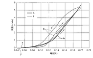
3)圧縮コイルばね34の力で、図3の電流と流量のグラフの傾きを調整し、かつコイル26への非通電状態で、球状弁体32を僅かに環状弁座14cに接触(当接)させる(必ずしも閉弁させる必要はない)。
4)圧縮コイルばね34の力より弱い力の主弁コイルばね33により、球状弁体32を環状弁座14cに着座させ(閉弁し)、感度を向上させる。つまり、図3の不感帯の長さyを小さくすることができる。 According to this double urging structure, the following action can be obtained.
1) The
2) Centering the axis of the valve element holder 31 (plunger 30) with the
3) The inclination of the current and flow rate graph of FIG. 3 is adjusted by the force of the
4) The main
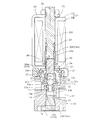
11 入口ポート
12 出口ポート
13 連通路
14 弁座ノズル
14c 環状弁座(弁座)
15 ロックナット
16 Oリング
20 プランジャガイド筒
21 ストッパリング
22 Oリング
23 プランジャ受けロッド
25 コイルハウジング
26 コイル
27 ソレノイド
29 ロックナット
30 プランジャ
31 弁体ホルダ
31t 内面テーパ孔
32 球状弁体(弁体)
33 主弁圧縮コイルばね
34 圧縮コイルばね(ばね手段、コイルばね) DESCRIPTION OF
15 Lock nut 16 O-
33 Main valve
Claims (4)
- 流体の入口ポート、出口ポート及び両ポートを連通させる連通路に位置する弁座を有するハウジング;
このハウジングに結合されたプランジャガイド筒;
先端部に上記弁座に接離する弁体を有し、上記プランジャガイド筒に軸方向移動自在に挿入されたプランジャ;
上記プランジャを弁体が弁座に当接する方向に付勢するばね手段;及び
このばね手段に抗して上記プランジャを開弁方向に移動させる電磁手段;
を備えた流量調整器において、
上記プランジャの外周面とプランジャガイド筒の内周面との間には、両者の軸線が一致した状態で両者を完全に非接触とし摺動抵抗をゼロとするに十分な隙間が存在すること;
上記弁体は球からなり、該弁体と弁座の一方は剛体、他方は弾性材料からなること;及び
上記ばね手段は、プランジャと同心の圧縮コイルばねからなり、プランジャガイド筒の固定部分と、プランジャ側の可動部分との間に張設されていること;
を特徴とする流量調整器。 A housing having a valve seat located in a fluid inlet port, an outlet port, and a communication passage communicating the two ports;
A plunger guide tube coupled to the housing;
A plunger having a valve body that comes into contact with and separates from the valve seat at the tip, and is inserted into the plunger guide cylinder so as to be axially movable;
Spring means for urging the plunger in a direction in which the valve body comes into contact with the valve seat; and electromagnetic means for moving the plunger in the valve opening direction against the spring means;
In a flow regulator with
There is a sufficient gap between the outer peripheral surface of the plunger and the inner peripheral surface of the plunger guide cylinder in a state where both axes are coincident with each other so that they are completely non-contact and the sliding resistance is zero;
The valve body is made of a sphere, and one of the valve body and the valve seat is made of a rigid body, and the other is made of an elastic material; and the spring means is made of a compression coil spring concentric with the plunger, , Stretched between the movable part on the plunger side;
A flow regulator characterized by. - 請求の範囲第1項記載の流量調整器において、上記プランジャの先端部には、該プランジャとは別部材からなる弁体ホルダが結合されており、この弁体ホルダは、上記球からなる弁体の先端一部を弁座側に突出させる内面テーパ孔を有し、上記弁体をこの内面テーパ孔から突出させる方向に付勢する、上記圧縮コイルばねと同心の主弁圧縮コイルばねがさらに設けられている流量調整器。 2. The flow rate regulator according to claim 1, wherein a valve body holder made of a member different from the plunger is coupled to a tip of the plunger, and the valve body holder is made of a valve body made of the sphere. There is further provided a main valve compression coil spring concentric with the compression coil spring, which has an inner tapered hole for projecting a part of the tip of the valve to the valve seat side and biases the valve body in a direction projecting from the inner tapered hole. The flow regulator that is being used.
- 請求の範囲第1項または第2項記載の流量調整器において、上記弁座は、ハウジングに軸方向の位置調節を自在に結合した弁座ノズルの弁体側端部に設けられている流量調整器。 The flow rate regulator according to claim 1 or 2, wherein the valve seat is provided at a valve body side end portion of a valve seat nozzle that is freely coupled to a housing for axial position adjustment. .
- 請求の範囲第1項ないし第3項のいずれか1項記載の流量調整器において、上記プランジャの外周面とプランジャガイド筒の内周面との間の隙間は、プランジャ外径を3.3~3.7mm、プランジャガイド筒内径を4.1~4.5mmとしたとき、0.2~0.6mmである流量調整器。 The flow rate regulator according to any one of claims 1 to 3, wherein the gap between the outer peripheral surface of the plunger and the inner peripheral surface of the plunger guide cylinder has a plunger outer diameter of 3.3 to A flow regulator of 0.2 to 0.6 mm when 3.7 mm and plunger guide cylinder inner diameter is 4.1 to 4.5 mm.
Priority Applications (3)
| Application Number | Priority Date | Filing Date | Title |
|---|---|---|---|
| CN201280050996.6A CN103890469B (en) | 2011-10-20 | 2012-06-28 | Flow regulator |
| US14/351,272 US9371933B2 (en) | 2011-10-20 | 2012-06-28 | Flow regulator |
| KR1020147009353A KR101541388B1 (en) | 2011-10-20 | 2012-06-28 | Flow regulator |
Applications Claiming Priority (2)
| Application Number | Priority Date | Filing Date | Title |
|---|---|---|---|
| JP2011-230608 | 2011-10-20 | ||
| JP2011230608A JP5684088B2 (en) | 2011-10-20 | 2011-10-20 | Flow regulator |
Publications (1)
| Publication Number | Publication Date |
|---|---|
| WO2013057983A1 true WO2013057983A1 (en) | 2013-04-25 |
Family
ID=48140643
Family Applications (1)
| Application Number | Title | Priority Date | Filing Date |
|---|---|---|---|
| PCT/JP2012/066506 WO2013057983A1 (en) | 2011-10-20 | 2012-06-28 | Flow regulator |
Country Status (6)
| Country | Link |
|---|---|
| US (1) | US9371933B2 (en) |
| JP (1) | JP5684088B2 (en) |
| KR (1) | KR101541388B1 (en) |
| CN (1) | CN103890469B (en) |
| TW (1) | TWI555937B (en) |
| WO (1) | WO2013057983A1 (en) |
Families Citing this family (4)
| Publication number | Priority date | Publication date | Assignee | Title |
|---|---|---|---|---|
| JP6170635B2 (en) * | 2014-10-07 | 2017-08-02 | 藤倉ゴム工業株式会社 | Multi-stage piston actuator |
| JP6638209B2 (en) * | 2015-04-13 | 2020-01-29 | 浜名湖電装株式会社 | solenoid valve |
| KR101821597B1 (en) * | 2016-05-10 | 2018-01-26 | 영도산업 주식회사 | Solenoid Valve for Fluid Control |
| JP6732202B2 (en) * | 2016-05-19 | 2020-07-29 | Smc株式会社 | solenoid valve |
Citations (7)
| Publication number | Priority date | Publication date | Assignee | Title |
|---|---|---|---|---|
| JPS4943218A (en) * | 1972-05-26 | 1974-04-23 | ||
| JPS5930980U (en) * | 1982-08-24 | 1984-02-25 | 三菱電機株式会社 | solenoid valve |
| JPS60138076U (en) * | 1984-02-24 | 1985-09-12 | 豊田工機株式会社 | electromagnetic relief valve |
| JPS61168369U (en) * | 1985-04-10 | 1986-10-18 | ||
| JPS6435273U (en) * | 1987-08-26 | 1989-03-03 | ||
| JPH01148180U (en) * | 1988-04-01 | 1989-10-13 | ||
| JP2003301962A (en) * | 2002-04-12 | 2003-10-24 | Saginomiya Seisakusho Inc | High-pressure compatible solenoid valve |
Family Cites Families (16)
| Publication number | Priority date | Publication date | Assignee | Title |
|---|---|---|---|---|
| US3107893A (en) * | 1961-08-31 | 1963-10-22 | Robbins Aviat Inc | Solenoid actuated fluid valve |
| US3578284A (en) * | 1969-03-28 | 1971-05-11 | Telsco Ind | Solenoid valve |
| JPS5023729U (en) * | 1973-06-27 | 1975-03-17 | ||
| JPS5930980A (en) | 1982-08-12 | 1984-02-18 | 王子製紙株式会社 | Bleaching of lignocellulose substance |
| JPS60138076A (en) | 1983-12-26 | 1985-07-22 | Hitachi Ltd | Chemical copper plating liquid |
| JPS61168369A (en) | 1985-01-18 | 1986-07-30 | 林 義夫 | Pain removing device |
| JPH087226B2 (en) * | 1987-07-30 | 1996-01-29 | パイオニア株式会社 | Method of determining the direction of rotation of a rotating body |
| JPH072110B2 (en) | 1987-12-04 | 1995-01-18 | 株式会社島津製作所 | Continuous sterilizer |
| JPH077661Y2 (en) * | 1988-09-02 | 1995-02-22 | エスエムシー株式会社 | solenoid valve |
| US5232196A (en) * | 1992-03-31 | 1993-08-03 | Ldi Pneutronics Corporation | Proportional solenoid controlled valve |
| US5611370A (en) * | 1994-11-10 | 1997-03-18 | Saturn Electronics & Engineering, Inc. | Proportional variable force solenoid control valve and transmission fluid control device |
| US5996628A (en) * | 1996-01-16 | 1999-12-07 | Saturn Electronics & Engineering, Inc. | Proportional variable force solenoid control valve |
| JP2001208233A (en) * | 2000-01-31 | 2001-08-03 | Aisin Seiki Co Ltd | Solenoid valve |
| US20060097210A1 (en) * | 2004-11-09 | 2006-05-11 | Fong Keith B | Composite armature for vehicle actuator valve |
| JP2007107451A (en) | 2005-10-13 | 2007-04-26 | Sanden Corp | Solenoid control valve of variable displacement swash plate type compressor |
| JP5234101B2 (en) | 2010-12-21 | 2013-07-10 | トヨタ自動車株式会社 | solenoid valve |
-
2011
- 2011-10-20 JP JP2011230608A patent/JP5684088B2/en active Active
-
2012
- 2012-06-27 TW TW101122947A patent/TWI555937B/en active
- 2012-06-28 KR KR1020147009353A patent/KR101541388B1/en active IP Right Grant
- 2012-06-28 US US14/351,272 patent/US9371933B2/en active Active
- 2012-06-28 WO PCT/JP2012/066506 patent/WO2013057983A1/en active Application Filing
- 2012-06-28 CN CN201280050996.6A patent/CN103890469B/en active Active
Patent Citations (7)
| Publication number | Priority date | Publication date | Assignee | Title |
|---|---|---|---|---|
| JPS4943218A (en) * | 1972-05-26 | 1974-04-23 | ||
| JPS5930980U (en) * | 1982-08-24 | 1984-02-25 | 三菱電機株式会社 | solenoid valve |
| JPS60138076U (en) * | 1984-02-24 | 1985-09-12 | 豊田工機株式会社 | electromagnetic relief valve |
| JPS61168369U (en) * | 1985-04-10 | 1986-10-18 | ||
| JPS6435273U (en) * | 1987-08-26 | 1989-03-03 | ||
| JPH01148180U (en) * | 1988-04-01 | 1989-10-13 | ||
| JP2003301962A (en) * | 2002-04-12 | 2003-10-24 | Saginomiya Seisakusho Inc | High-pressure compatible solenoid valve |
Also Published As
| Publication number | Publication date |
|---|---|
| JP5684088B2 (en) | 2015-03-11 |
| KR20140064939A (en) | 2014-05-28 |
| CN103890469A (en) | 2014-06-25 |
| US9371933B2 (en) | 2016-06-21 |
| TW201317489A (en) | 2013-05-01 |
| KR101541388B1 (en) | 2015-08-03 |
| JP2013087905A (en) | 2013-05-13 |
| TWI555937B (en) | 2016-11-01 |
| CN103890469B (en) | 2015-12-23 |
| US20140312256A1 (en) | 2014-10-23 |
Similar Documents
| Publication | Publication Date | Title |
|---|---|---|
| WO2017024795A1 (en) | Electronic expansion valve | |
| EP2492559B1 (en) | Solenoid valve | |
| US20170074417A1 (en) | Electromagnetic control valve | |
| US10823162B2 (en) | Variable-capacity compressor control valve | |
| WO2013057983A1 (en) | Flow regulator | |
| US20160131276A1 (en) | Electromagnetic control valve | |
| US8042789B2 (en) | Valve for distributing fluids | |
| US8936040B2 (en) | Solenoid valve | |
| US10941830B2 (en) | Shock absorber | |
| JP5468932B2 (en) | Solenoid control valve | |
| JP2015224649A (en) | Two-stage pilot type solenoid valve | |
| TW201937091A (en) | Poppet switch valve device and method for manufacturing poppet switch valve device | |
| WO2021098522A1 (en) | Gas proportional valve | |
| JP5944884B2 (en) | On-off valve | |
| CN112747122A (en) | Gas proportional valve | |
| JP6167010B2 (en) | Pilot type control valve | |
| KR102406952B1 (en) | Flow control valve | |
| JP2009019742A (en) | Bleed type valve device | |
| US10054245B2 (en) | Valve assembly with vent port between supply port and control port | |
| US20180355993A1 (en) | Hydraulic valve configuration for nh vbs with a nl solenoid | |
| US20170102087A1 (en) | Control Assembly for a Valve | |
| WO2022185451A1 (en) | Proportional valve | |
| US10955064B2 (en) | Solenoid valve assembly and method of assembling the same | |
| US20210025512A1 (en) | Variable-capacity compressor control valve | |
| US10018170B2 (en) | Integrated arrangement of a high-pressure valve and an injection rail |
Legal Events
| Date | Code | Title | Description |
|---|---|---|---|
| 121 | Ep: the epo has been informed by wipo that ep was designated in this application |
Ref document number: 12842670 Country of ref document: EP Kind code of ref document: A1 |
|
| ENP | Entry into the national phase |
Ref document number: 20147009353 Country of ref document: KR Kind code of ref document: A |
|
| WWE | Wipo information: entry into national phase |
Ref document number: 14351272 Country of ref document: US |
|
| NENP | Non-entry into the national phase |
Ref country code: DE |
|
| 122 | Ep: pct application non-entry in european phase |
Ref document number: 12842670 Country of ref document: EP Kind code of ref document: A1 |