WO2013046540A1 - Orbital sander - Google Patents
Orbital sander Download PDFInfo
- Publication number
- WO2013046540A1 WO2013046540A1 PCT/JP2012/005482 JP2012005482W WO2013046540A1 WO 2013046540 A1 WO2013046540 A1 WO 2013046540A1 JP 2012005482 W JP2012005482 W JP 2012005482W WO 2013046540 A1 WO2013046540 A1 WO 2013046540A1
- Authority
- WO
- WIPO (PCT)
- Prior art keywords
- base
- main
- guiding
- guided
- side guiding
- Prior art date
- Legal status (The legal status is an assumption and is not a legal conclusion. Google has not performed a legal analysis and makes no representation as to the accuracy of the status listed.)
- Ceased
Links
Images




Classifications
-
- B—PERFORMING OPERATIONS; TRANSPORTING
- B24—GRINDING; POLISHING
- B24B—MACHINES, DEVICES, OR PROCESSES FOR GRINDING OR POLISHING; DRESSING OR CONDITIONING OF ABRADING SURFACES; FEEDING OF GRINDING, POLISHING, OR LAPPING AGENTS
- B24B23/00—Portable grinding machines, e.g. hand-guided; Accessories therefor
- B24B23/02—Portable grinding machines, e.g. hand-guided; Accessories therefor with rotating grinding tools; Accessories therefor
- B24B23/03—Portable grinding machines, e.g. hand-guided; Accessories therefor with rotating grinding tools; Accessories therefor the tool being driven in a combined movement
Definitions
- the present invention relates to an orbital sander.
- the orbital sander has been known as an electric power tool for polishing a surface of a workpiece or the like.
- the orbital sander has a main body, a motor housed in the main body, an output shaft portion that penetrates a part of the main body to externally extend from the inside of the main body to the outside of the main body and is driven by the rotation of the motor, and a base that is placed face to face with the main body and makes an orbital movement in a direction substantially orthogonal to the output shaft portion by the driving of the output shaft portion (see Patent Literature 1).
- an object of the present invention is to provide an orbital sander that can significantly reduce the abrasion of the member on the main body side as well as the abrasion of the member on the base side.
- the present invention provides an orbital sander including: a motor supported on a main body; an output shaft portion driven by rotation of the motor; and a base that makes an orbital movement in a direction crossing the output shaft portion by driving of the output shaft portion, and further including: a main-body-side guiding portion provided in the main body; and a base-side guided portion that is provided in a part of an outer surface of the base facing the main-body-side guiding portion so as to face the main-body-side guiding portion, in which a polishing member is provided to the base, and a movable guiding member which guides the base-side guided portion with respect to the main-body-side guiding portion is provided between the base-side guided portion and the main-body-side guiding portion so that the base moves only in a direction crossing the output shaft portion.
- a movable guiding member which can guide the base-side guided portion with respect to the main-body-side guiding portion is provided between a base-side guided portion and a main-body-side guiding portion so that the base can move only in a direction crossing the output shaft portion. Therefore, it is possible to suppress the main-body-side guiding portion and the base-side guided portion from sliding on each other to be respectively worn out when the base makes the orbital movement. Thus, an orbital sander that is superior in durability can be realized.
- the output shaft portion penetrates a part of the main body to externally extend from an inside of the main body to an outside of the main body and is driven by rotation of the motor housed in the main body, a plurality of the main-body-side guiding portions are disposed on an outer surface of the main body so as to surround the output shaft portion, the base is disposed so as to face the plurality of main-body-side guiding portions, a plurality of the base-side guided portions are disposed so as to face each of the plurality of main-body-side guiding portions, and the movable guiding member guides the base-side guided portion with respect to the main-body-side guiding portion so that the base can move in a direction crossing the output shaft portion and also a distance between the main-body-side guiding portion and the base-side guided portion can be constant when the base moves.
- a main-body-side guiding concave portion that recesses in a direction away from the base-side guided portion is formed in a portion of the main-body-side guiding portion facing the base-side guided portion
- a base-side guided concave portion that recesses in a direction away from the main-body-side guiding portion is formed in a portion of the base-side guided portion facing the main-body-side guiding portion
- the movable guiding member is a ball having one portion housed in the main-body-side guiding concave portion and the other one portion housed in the base-side guided concave portion.
- the main-body-side guiding concave portion is defined and formed by a main-body-side guiding portion bottom surface that is in parallel with a direction crossing the output shaft portion and a main-body-side guiding portion side wall that is formed so as to stand relative to the main-body-side guiding portion bottom surface, and the ball makes contact with each of the main-body-side guiding portion bottom surface and the main-body-side guiding portion side wall at one point.
- the one ball makes contact with each of the main-body-side guiding portion bottom surface and the main-body-side guiding portion side wall at one point (at two points in total), it is possible to prevent the ball from coming off the main-body-side guiding concave portion.
- a cross section of the main-body-side guiding concave portion that is in parallel with the main-body-side guiding portion bottom surface has a circular shape.
- the ball when the base makes an orbital movement, the ball can smoothly roll on the main-body-side guiding portion side wall.
- the base-side guided concave portion is defined and formed by a base-side guided portion bottom surface that is in parallel with a direction crossing the output shaft portion and a base-side guided portion side wall that is formed so as to stand relative to the base-side guided portion bottom surface, and the ball makes contact with each of the base-side guided portion bottom surface and the base-side guided portion side wall at one point.
- the one ball makes contact with each of the base-side guided portion bottom surface and the base-side guided portion side wall at one point (at two points in total), it is possible to prevent the ball from coming off the base-side guided concave portion.
- a cross section of the base-side guided concave portion that is in parallel with the base-side guided portion bottom surface has a circular shape.
- the ball when the base makes an orbital movement, the ball can smoothly roll on the base-side guided portion side wall.
- FIG. 1 is a cross-sectional view showing a side portion of an orbital sander according to an embodiment of the present invention.
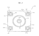
- FIG. 2 is a schematic plan view showing a base of the orbital sander according to the embodiment of the present invention.
- FIG. 3 is a perspective view showing a base-side foot and a ball of the orbital sander according to the embodiment of the present invention.
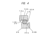
- FIG. 4 is a cross-sectional view showing a main-body-side foot, a base-side foot and a ball of the orbital sander according to the embodiment of the present invention.
- FIG. 5 is a perspective view showing a base-side foot and a ball of a first modified example of the orbital sander according to the embodiment of the present invention.
- FIG. 1 is a cross-sectional view showing a side portion of an orbital sander according to an embodiment of the present invention.
- FIG. 2 is a schematic plan view showing a base of the orbital sander according to the embodiment of the
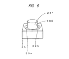
- FIG. 6 is a perspective view showing a base-side foot and a ball of a second modified example of the orbital sander according to the embodiment of the present invention.
- FIG. 7 is a perspective view showing a base-side foot and a ball of a third modified example of the orbital sander according to the embodiment of the present invention.
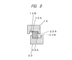
- FIG. 8 is a cross-sectional view showing a main-body-side foot, a base-side foot, and a ball of the third modified example of the orbital sander according to the embodiment of the present invention.
- the orbital sander 1 which is an electric power tool shown in FIG. 1, is a tool for polishing a surface of a workpiece or the like and is provided with a main body 10, a motor 20 and a base 30.
- a direction from the main body 10 toward the base 30 is defined as a downward direction, and a direction reverse to this is defined as an upward direction.
- a rightward direction of FIG. 1 is defined as a frontward direction, and a leftward direction thereof is defined as a rearward direction.
- a direction from the front surface to the rear surface of the drawing is defined as a leftward direction
- a direction from the rear surface to the front surface of the drawing is defined as a rightward direction.
- the main body 10 has a hollow box shape.
- a through hole 10a that communicates the inside and the outside of the main body 10 with each other is formed, and a bearing 11, that is, a ball bearing is provided in the through hole 10a.
- the motor 20 is secured to the main body 10 and housed in the main body 10, and the output shaft of the motor 20 extends from the inside of the main body 10 to the outside of the main body 10 through the through hole 10a.
- the output shaft of the motor 20 corresponds to the output shaft portion.
- an inlet (not shown) is formed in a part of an upper wall 10C of the main body 10
- an outlet (not shown) to discharge air that flows in through the unshown inlet is formed.
- an exhaust pipe 10D is provided on the outside of the lower wall 10A of the main body 10.
- One end of the exhaust pipe 10D has an opening adjacent to the lower wall 10A of the main body 10, and a dust collecting bag (not shown) is attached to the other end of the exhaust pipe 10D.
- main-body-side feet 12 are provided on the lower wall 10A of the main body 10.
- the main-body-side feet 12 are made of resin (for example, made of nylon resin), and one foot 12 is provided near each of four corners of the lower wall 10A of the main body 10 having a substantially rectangular shape, that is, four feet 12 are provided in total.
- the outside shape of each main-body-side foot 12 is a substantially rectangular parallelepiped shape.
- a main-body-side foot concave portion 12a having a truncated cone shape that is recessed upward with its diameter being narrowed toward the top is formed.
- the main-body-side foot concave portion 12a is defined and formed by a main-body-side foot bottom surface 12A that is in parallel with a direction substantially orthogonal to the axial direction of the output shaft of the fan 21 and a main-body-side foot side wall 12B that is placed so as to stand relative to the main-body-side foot bottom surface 12A and is formed on the periphery of the main-body-side foot bottom surface 12A so as to surround the main-body-side foot bottom surface 12A.
- the depth of the main-body-side foot concave portion 12a in the vertical direction is about 3 mm to 7 mm.
- the main-body-side foot 12 corresponds to the main-body-side guiding portion.
- a fan cover 13 is attached to the lower wall 10A of the main body 10.
- the fan cover 13 has a portion surrounding the outer periphery of a blade portion 21B of the fan 21 described later and a plate-shaped cover lower wall 13A that surrounds the lower side of the blade portion 21B of the fan 21 described later and extends in a direction orthogonal to the output shaft of the motor 20.
- the fan 21 is secured to the output shaft of the motor 20.
- the fan 21 is a centrifugal fan 21, and it has a fan shaft portion 21A and the blade portion 21B that outwardly expands in the radial direction of the fan shaft portion 21A like a flange from the fan shaft portion 21A.
- the output shaft of the motor 20 penetrates the fan shaft portion 21A so as to have a mutually coaxial positional relationship with each other.
- the fan shaft portion 21A is secured to the output shaft of the motor 20 with a screw 23 that is engaged with the lower end of the output shaft of the motor 20 with a washer 22 interpolated therebetween.
- a narrowed diameter portion 21C having a diameter smaller than that of an upper portion is formed at a lower portion of the fan shaft portion 21A.
- the cross section of the upper portion of the fan shaft portion 21A orthogonal to the axial direction of the fan shaft portion 21A and the cross section of the narrowed diameter portion 21C orthogonal to the axial direction of the fan shaft portion 21 respectively have circular shapes, but the shaft center of the narrowed diameter portion 21C deviates from the shaft center of the upper portion of the fan shaft portion 21A. Therefore, when the upper portion of the fan shaft portion 21A is coaxially rotated integrally with the output shaft of the motor 20 by the rotation of the output shaft of the motor 20, the narrowed diameter portion 21C is eccentrically rotated.
- the base 30 is received and supported by the narrowed diameter portion 21C with the bearing 31 interpolated therebetween.
- the base 30 is rotatable relative to the lower end portion of the narrowed diameter portion 21C.
- the base 30 has a plate-like outer shape having a substantially rectangular shape, and as shown in FIG. 2, a circular through hole 30a is formed in the center portion thereof.
- the bearing 31 is made up of a ball bearing and is placed at a part of the base 30 that forms the through hole 30a. Therefore, when the narrowed diameter portion 21C is rotated eccentrically, the base 30 makes an orbital movement in a direction substantially orthogonal to the fan shaft portion 21A.
- a sandpaper, a sand cloth, or the like (not shown) is fixed to the entire lower surface of the base 30.
- a ring shaped felt 32 is attached to the upper surface of the base 30.
- the felt 32 is engaged with a ring shaped groove formed on the upper surface of the base 30 coaxially with the fan shaft portion 21A so as to be secured onto the base 30, and it annularly surrounds the fan shaft portion 21A in a coaxial positional relationship with the fan shaft portion 21A.
- the cover lower wall 13A of the fan cover 13 is in contact with the felt 32. Since the felt 32 is provided, sealability of a space surrounded by the main body 10 and the base 30, in which the fan 21 is rotated, is improved, which enables this space to have a higher negative pressure. Moreover, since the felt 32 is soft, the cover lower wall 13A of the fan cover 13 slides on the felt 32, and thus the vibration of the base 30 relative to the main body 10 generated when the base 30 makes an orbital movement can be absorbed by the felt 32.
- base-side feet 33 are provided on the upper surface of the base 30.
- the base-side feet 33 are made of resin (for example, made of nylon resin), and the outer shape thereof is a substantially rectangular parallelepiped shape that is substantially the same shape as that of the main-body-side foot 12. As shown in FIG. 2, one base-side foot 33 is provided near each of four corners of the upper surface of the base 30 having a substantially rectangular shape, that is, four base-side feet 33 are provided in total.
- the upper surface of each base-side foot 33 is disposed to face the lower surface of each main-body-side foot 12 in the vertical direction so as to have respectively consistent positional relationship.
- each base-side foot 33 In the center of the upper surface of each base-side foot 33, a base-side foot concave portion 33a having the same shape as that of the main-body-side foot concave portion 12a is formed. That is, the base-side foot concave portion 33a has a truncated cone shape that is recessed downward with its diameter being narrowed toward the bottom.
- the base-side foot concave portion 33a is defined and formed by a base-side foot bottom surface 33A that is in parallel with a direction substantially orthogonal to the axial direction of the fan shaft portion 21A and a base-side foot side wall 33B that is placed so as to stand relative to the base-side foot bottom surface 33A and is formed on the periphery of the base-side foot bottom surface 33A so as to surround the base-side foot bottom surface 33A.
- the depth of the base-side foot concave portion 33a in the vertical direction is about 3 mm to 7 mm.
- the base-side foot 33 corresponds to the base-side guided portion.
- a ball 34 is placed each between the main-body-side foot 12 and the base-side foot 33 that form a pair in the vertical direction.
- the ball 34 is made of rubber and has a diameter of about 7 mm to 15 mm.
- the substantially upper half thereof is housed inside the main-body-side foot concave portion 12a, and the substantially lower half thereof is housed inside the base-side foot concave portion 33a.
- the upper end of the ball 34 is always in contact with the main-body-side foot bottom surface 12A, and the lower end of the ball 34 is always in contact with the base-side foot bottom surface 33A.
- the ball 34 is moved inside the main-body-side foot concave portion 12a in a direction substantially orthogonal to the fan shaft portion 21A by the orbital movement of the base 30, as shown in FIG. 4, the ball 34 makes contact with the main-body-side foot side wall 12B not only at its upper end, but also at its side portion. More specifically, the ball 34 makes contact with the main-body-side foot 12 at two points.
- the ball 34 when the ball 34 is moved inside the base-side foot concave portion 33a in a direction substantially orthogonal to the fan shaft portion 21A by the orbital movement of the base 30, as shown in FIG. 4, the ball 34 makes contact with the base-side foot side wall 33B not only at its lower end, but also at its side portion. More specifically, the ball 34 makes contact with the base-side foot 33 at two points. Since the ball 34 is provided between the main-body-side foot 12 and the base-side foot 33, a gap is formed between the lower end surface of the main-body-side foot 12 and the upper end surface of the base-side foot 33. The ball 34 corresponds to the movable guiding member.
- the ball 34 which serves as a movable guiding member capable of guiding the base-side foot 33 with respect to the main-body-side foot 12, is provided so that the base 30 is moved in a direction crossing the fan shaft portion 21A in a state of the base-side foot 33 and the main-body-side foot 12 being separated from each other. Therefore, it is possible to suppress the main-body-side foot 12 and the base-side foot 33 from sliding on each other to be respectively worn out when the base 30 makes the orbital movement. Thus, the durability of the orbital sander 1 is improved.
- the main-body-side foot concave portion 12a which recesses in a direction away from the base-side foot 33, is formed in the portion of the main-body-side foot 12 facing the base-side foot 33
- the base-side foot concave portion 33a which recesses in a direction away from the main-body-side foot 12
- the movable guiding member is prepared as the ball 34 having one portion housed in the main-body-side foot concave portion 12a and the other one portion housed in the base-side foot concave portion 33a. Therefore, by utilizing the rolling of the ball 34, it is possible to easily suppress the main-body-side foot 12 and the base-side foot 33 from sliding on each other with a simple structure when the base 30 makes the orbital movement.
- the one ball 34 makes contact with the main-body-side foot bottom surface 12A and the main-body-side foot side wall 12B respectively at one point, that is, at two points in total, it is possible to prevent the ball 34 from coming off the main-body-side foot concave portion 12a. Also, since the one ball 34 makes contact with the base-side foot bottom surface 33A and the base-side foot side wall 33B respectively at one point, that is, at two points in total, it is possible to prevent the ball 34 from coming off the base-side foot concave portion 33a.
- the ball 34 can smoothly roll on the main-body-side foot side wall 12B when the base 30 makes the orbital movement. Also, since the cross section of the base-side foot concave portion 33a that is in parallel with the base-side foot bottom surface 33A has a circular shape, the ball 34 can smoothly roll on the base-side foot side wall 33B when the base 30 makes the orbital movement.
- the ball 34 is made of rubber and the base-side foot 33 and the main-body-side foot 12 are made of resin respectively, the ball 34 is comparatively soft relative to the base-side foot 33 and the main-body-side foot 12. Therefore, vibration of the base 30 with respect to the main body 10 in a direction away from the main body 10 can be absorbed by the ball 34.
- the orbital sander of the present invention is not limited to the above-described embodiments, but various changes can be made within the scope of the claims.
- the shapes of the main-body-side foot, the base-side foot and the movable guiding member are not limited to those of the present embodiment.
- the outer shapes of the main-body-side foot and the base-side foot 133 may be substantially columnar shapes.
- a column-shaped low-friction slidable member 234 serving as the movable guiding member may be used so that the axial direction thereof would be oriented in the vertical direction.
- those having columnar outer shapes may be used as the main-body-side foot and a base-side foot 333.
- the column-shaped low-friction slidable member 234 when used as the movable guiding member, when the column-shaped low-friction slidable member 234 moves within the main-body-side foot concave portion 12a and the base-side foot concave portion 33a in a direction substantially orthogonal to the fan shaft portion 21A by the orbital movement of the base 30, as shown in FIG. 8, the entire bottom surface of the column-shaped low-friction slidable member 234 makes contact with the base-side foot bottom surface 33A, and the lower portion of the side surface of the column-shaped low-friction slidable member 234 makes contact with the base-side foot side wall 33B.
- the entire upper surface of the column-shaped low-friction slidable member 234 makes contact with the main-body-side foot bottom surface 12A, and the upper portion of the side surface of the column-shaped low-friction slidable member 234 makes contact with the main-body-side foot side wall 12B.
- the movable guiding member is not limited to that of the above-mentioned embodiment, and any low-friction slidable member may be used.
- the present invention can be effectively applied to the field of the orbital sander.
Landscapes
- Engineering & Computer Science (AREA)
- Mechanical Engineering (AREA)
- Finish Polishing, Edge Sharpening, And Grinding By Specific Grinding Devices (AREA)
Abstract
A main-body-side foot 12 is provided near each of four corners of a substantially rectangular lower wall 10A of a main body 10 (four in total), a main-body-side foot concave portion 12a is formed in the center of the lower surface of each main-body-side foot 12, a base-side foot 33 is provided near each of four corners of a substantially rectangular upper surface of a base 30 (four in total), the upper surface of each base-side foot 33 is disposed to face the lower surface of each main-body-side foot 12 in the vertical direction so as to have respectively consistent positional relationship, a base-side foot concave portion 33a is formed in the center of the upper surface of each base-side foot 33, and one ball 34 is provided each between the main-body-side foot 12 and the base-side foot 33 that form a pair in the vertical direction.
Description
The present invention relates to an orbital sander.
Conventionally, the orbital sander has been known as an electric power tool for polishing a surface of a workpiece or the like. The orbital sander has a main body, a motor housed in the main body, an output shaft portion that penetrates a part of the main body to externally extend from the inside of the main body to the outside of the main body and is driven by the rotation of the motor, and a base that is placed face to face with the main body and makes an orbital movement in a direction substantially orthogonal to the output shaft portion by the driving of the output shaft portion (see Patent Literature 1).
Since the base makes an orbital movement with respect to the main body in the orbital sander, for example, a member on the main body side and a member on the base side slide on each other to be worn out. Therefore, an object of the present invention is to provide an orbital sander that can significantly reduce the abrasion of the member on the main body side as well as the abrasion of the member on the base side.
The present invention provides an orbital sander including: a motor supported on a main body; an output shaft portion driven by rotation of the motor; and a base that makes an orbital movement in a direction crossing the output shaft portion by driving of the output shaft portion, and further including: a main-body-side guiding portion provided in the main body; and a base-side guided portion that is provided in a part of an outer surface of the base facing the main-body-side guiding portion so as to face the main-body-side guiding portion, in which a polishing member is provided to the base, and a movable guiding member which guides the base-side guided portion with respect to the main-body-side guiding portion is provided between the base-side guided portion and the main-body-side guiding portion so that the base moves only in a direction crossing the output shaft portion.
In the present invention, a movable guiding member which can guide the base-side guided portion with respect to the main-body-side guiding portion is provided between a base-side guided portion and a main-body-side guiding portion so that the base can move only in a direction crossing the output shaft portion. Therefore, it is possible to suppress the main-body-side guiding portion and the base-side guided portion from sliding on each other to be respectively worn out when the base makes the orbital movement. Thus, an orbital sander that is superior in durability can be realized.
In one embodiment of the present invention, the output shaft portion penetrates a part of the main body to externally extend from an inside of the main body to an outside of the main body and is driven by rotation of the motor housed in the main body, a plurality of the main-body-side guiding portions are disposed on an outer surface of the main body so as to surround the output shaft portion, the base is disposed so as to face the plurality of main-body-side guiding portions, a plurality of the base-side guided portions are disposed so as to face each of the plurality of main-body-side guiding portions, and the movable guiding member guides the base-side guided portion with respect to the main-body-side guiding portion so that the base can move in a direction crossing the output shaft portion and also a distance between the main-body-side guiding portion and the base-side guided portion can be constant when the base moves.
In another embodiment of the present invention, a main-body-side guiding concave portion that recesses in a direction away from the base-side guided portion is formed in a portion of the main-body-side guiding portion facing the base-side guided portion, a base-side guided concave portion that recesses in a direction away from the main-body-side guiding portion is formed in a portion of the base-side guided portion facing the main-body-side guiding portion, and the movable guiding member is a ball having one portion housed in the main-body-side guiding concave portion and the other one portion housed in the base-side guided concave portion.
In this embodiment, by utilizing the rolling of the ball, it is possible to easily suppress the main-body-side guiding portion and the base-side guided portion from sliding on each other with a simple structure when the base makes the orbital movement.
In another embodiment of the present invention, the main-body-side guiding concave portion is defined and formed by a main-body-side guiding portion bottom surface that is in parallel with a direction crossing the output shaft portion and a main-body-side guiding portion side wall that is formed so as to stand relative to the main-body-side guiding portion bottom surface, and the ball makes contact with each of the main-body-side guiding portion bottom surface and the main-body-side guiding portion side wall at one point.
In this embodiment, since the one ball makes contact with each of the main-body-side guiding portion bottom surface and the main-body-side guiding portion side wall at one point (at two points in total), it is possible to prevent the ball from coming off the main-body-side guiding concave portion.
In another embodiment of the present invention, a cross section of the main-body-side guiding concave portion that is in parallel with the main-body-side guiding portion bottom surface has a circular shape. In this embodiment, when the base makes an orbital movement, the ball can smoothly roll on the main-body-side guiding portion side wall.
In another embodiment of the present invention, the base-side guided concave portion is defined and formed by a base-side guided portion bottom surface that is in parallel with a direction crossing the output shaft portion and a base-side guided portion side wall that is formed so as to stand relative to the base-side guided portion bottom surface, and the ball makes contact with each of the base-side guided portion bottom surface and the base-side guided portion side wall at one point.
In this embodiment, since the one ball makes contact with each of the base-side guided portion bottom surface and the base-side guided portion side wall at one point (at two points in total), it is possible to prevent the ball from coming off the base-side guided concave portion.
In another embodiment of the present invention, a cross section of the base-side guided concave portion that is in parallel with the base-side guided portion bottom surface has a circular shape. In this embodiment, when the base makes an orbital movement, the ball can smoothly roll on the base-side guided portion side wall.
In accordance with the present invention, it is possible to significantly reduce the abrasion of the member on the main body side as well as the abrasion of the member on the base side of an orbital sander.
An orbital sander according to an embodiment of the present invention will be described with reference to FIGs. 1 to 3. The orbital sander 1, which is an electric power tool shown in FIG. 1, is a tool for polishing a surface of a workpiece or the like and is provided with a main body 10, a motor 20 and a base 30. For convenience of the following description, a direction from the main body 10 toward the base 30 is defined as a downward direction, and a direction reverse to this is defined as an upward direction. Also, a rightward direction of FIG. 1 is defined as a frontward direction, and a leftward direction thereof is defined as a rearward direction. Moreover, a direction from the front surface to the rear surface of the drawing is defined as a leftward direction, and a direction from the rear surface to the front surface of the drawing is defined as a rightward direction.
The main body 10 has a hollow box shape. In the substantially center portion of a lower wall 10A of the main body 10, a through hole 10a that communicates the inside and the outside of the main body 10 with each other is formed, and a bearing 11, that is, a ball bearing is provided in the through hole 10a. The motor 20 is secured to the main body 10 and housed in the main body 10, and the output shaft of the motor 20 extends from the inside of the main body 10 to the outside of the main body 10 through the through hole 10a. The output shaft of the motor 20 corresponds to the output shaft portion. In a part of a side wall 10B of the main body 10 close to the motor 20, an inlet (not shown) is formed. In a part of an upper wall 10C of the main body 10, an outlet (not shown) to discharge air that flows in through the unshown inlet is formed.
Further, an exhaust pipe 10D is provided on the outside of the lower wall 10A of the main body 10. One end of the exhaust pipe 10D has an opening adjacent to the lower wall 10A of the main body 10, and a dust collecting bag (not shown) is attached to the other end of the exhaust pipe 10D. With this structure, abrasive powder that flows in from one end of the exhaust pipe 10D by an air flow caused by the rotation of a fan 21 described later is collected into the unshown dust collecting bag.
Further, main-body-side feet 12 are provided on the lower wall 10A of the main body 10. The main-body-side feet 12 are made of resin (for example, made of nylon resin), and one foot 12 is provided near each of four corners of the lower wall 10A of the main body 10 having a substantially rectangular shape, that is, four feet 12 are provided in total. The outside shape of each main-body-side foot 12 is a substantially rectangular parallelepiped shape. In the center of the lower surface of each main-body-side foot 12, as shown in FIG. 4, a main-body-side foot concave portion 12a having a truncated cone shape that is recessed upward with its diameter being narrowed toward the top is formed. More specifically, the main-body-side foot concave portion 12a is defined and formed by a main-body-side foot bottom surface 12A that is in parallel with a direction substantially orthogonal to the axial direction of the output shaft of the fan 21 and a main-body-side foot side wall 12B that is placed so as to stand relative to the main-body-side foot bottom surface 12A and is formed on the periphery of the main-body-side foot bottom surface 12A so as to surround the main-body-side foot bottom surface 12A. The depth of the main-body-side foot concave portion 12a in the vertical direction is about 3 mm to 7 mm. The main-body-side foot 12 corresponds to the main-body-side guiding portion.
Also, a fan cover 13 is attached to the lower wall 10A of the main body 10. The fan cover 13 has a portion surrounding the outer periphery of a blade portion 21B of the fan 21 described later and a plate-shaped cover lower wall 13A that surrounds the lower side of the blade portion 21B of the fan 21 described later and extends in a direction orthogonal to the output shaft of the motor 20.
The fan 21 is secured to the output shaft of the motor 20. The fan 21 is a centrifugal fan 21, and it has a fan shaft portion 21A and the blade portion 21B that outwardly expands in the radial direction of the fan shaft portion 21A like a flange from the fan shaft portion 21A. The output shaft of the motor 20 penetrates the fan shaft portion 21A so as to have a mutually coaxial positional relationship with each other. The fan shaft portion 21A is secured to the output shaft of the motor 20 with a screw 23 that is engaged with the lower end of the output shaft of the motor 20 with a washer 22 interpolated therebetween. A narrowed diameter portion 21C having a diameter smaller than that of an upper portion is formed at a lower portion of the fan shaft portion 21A. The cross section of the upper portion of the fan shaft portion 21A orthogonal to the axial direction of the fan shaft portion 21A and the cross section of the narrowed diameter portion 21C orthogonal to the axial direction of the fan shaft portion 21 respectively have circular shapes, but the shaft center of the narrowed diameter portion 21C deviates from the shaft center of the upper portion of the fan shaft portion 21A. Therefore, when the upper portion of the fan shaft portion 21A is coaxially rotated integrally with the output shaft of the motor 20 by the rotation of the output shaft of the motor 20, the narrowed diameter portion 21C is eccentrically rotated.
The base 30 is received and supported by the narrowed diameter portion 21C with the bearing 31 interpolated therebetween. The base 30 is rotatable relative to the lower end portion of the narrowed diameter portion 21C. The base 30 has a plate-like outer shape having a substantially rectangular shape, and as shown in FIG. 2, a circular through hole 30a is formed in the center portion thereof. The bearing 31 is made up of a ball bearing and is placed at a part of the base 30 that forms the through hole 30a. Therefore, when the narrowed diameter portion 21C is rotated eccentrically, the base 30 makes an orbital movement in a direction substantially orthogonal to the fan shaft portion 21A. A sandpaper, a sand cloth, or the like (not shown) is fixed to the entire lower surface of the base 30.
Further, a ring shaped felt 32 is attached to the upper surface of the base 30. The felt 32 is engaged with a ring shaped groove formed on the upper surface of the base 30 coaxially with the fan shaft portion 21A so as to be secured onto the base 30, and it annularly surrounds the fan shaft portion 21A in a coaxial positional relationship with the fan shaft portion 21A. The cover lower wall 13A of the fan cover 13 is in contact with the felt 32. Since the felt 32 is provided, sealability of a space surrounded by the main body 10 and the base 30, in which the fan 21 is rotated, is improved, which enables this space to have a higher negative pressure. Moreover, since the felt 32 is soft, the cover lower wall 13A of the fan cover 13 slides on the felt 32, and thus the vibration of the base 30 relative to the main body 10 generated when the base 30 makes an orbital movement can be absorbed by the felt 32.
Furthermore, base-side feet 33 are provided on the upper surface of the base 30. The base-side feet 33 are made of resin (for example, made of nylon resin), and the outer shape thereof is a substantially rectangular parallelepiped shape that is substantially the same shape as that of the main-body-side foot 12. As shown in FIG. 2, one base-side foot 33 is provided near each of four corners of the upper surface of the base 30 having a substantially rectangular shape, that is, four base-side feet 33 are provided in total. The upper surface of each base-side foot 33 is disposed to face the lower surface of each main-body-side foot 12 in the vertical direction so as to have respectively consistent positional relationship. In the center of the upper surface of each base-side foot 33, a base-side foot concave portion 33a having the same shape as that of the main-body-side foot concave portion 12a is formed. That is, the base-side foot concave portion 33a has a truncated cone shape that is recessed downward with its diameter being narrowed toward the bottom. More specifically, the base-side foot concave portion 33a is defined and formed by a base-side foot bottom surface 33A that is in parallel with a direction substantially orthogonal to the axial direction of the fan shaft portion 21A and a base-side foot side wall 33B that is placed so as to stand relative to the base-side foot bottom surface 33A and is formed on the periphery of the base-side foot bottom surface 33A so as to surround the base-side foot bottom surface 33A. The depth of the base-side foot concave portion 33a in the vertical direction is about 3 mm to 7 mm. The base-side foot 33 corresponds to the base-side guided portion.
A ball 34 is placed each between the main-body-side foot 12 and the base-side foot 33 that form a pair in the vertical direction. The ball 34 is made of rubber and has a diameter of about 7 mm to 15 mm. The substantially upper half thereof is housed inside the main-body-side foot concave portion 12a, and the substantially lower half thereof is housed inside the base-side foot concave portion 33a.
The upper end of the ball 34 is always in contact with the main-body-side foot bottom surface 12A, and the lower end of the ball 34 is always in contact with the base-side foot bottom surface 33A. When the ball 34 is moved inside the main-body-side foot concave portion 12a in a direction substantially orthogonal to the fan shaft portion 21A by the orbital movement of the base 30, as shown in FIG. 4, the ball 34 makes contact with the main-body-side foot side wall 12B not only at its upper end, but also at its side portion. More specifically, the ball 34 makes contact with the main-body-side foot 12 at two points. Similarly, when the ball 34 is moved inside the base-side foot concave portion 33a in a direction substantially orthogonal to the fan shaft portion 21A by the orbital movement of the base 30, as shown in FIG. 4, the ball 34 makes contact with the base-side foot side wall 33B not only at its lower end, but also at its side portion. More specifically, the ball 34 makes contact with the base-side foot 33 at two points. Since the ball 34 is provided between the main-body-side foot 12 and the base-side foot 33, a gap is formed between the lower end surface of the main-body-side foot 12 and the upper end surface of the base-side foot 33. The ball 34 corresponds to the movable guiding member.
Between the base-side foot 33 and the main-body-side foot 12, the ball 34, which serves as a movable guiding member capable of guiding the base-side foot 33 with respect to the main-body-side foot 12, is provided so that the base 30 is moved in a direction crossing the fan shaft portion 21A in a state of the base-side foot 33 and the main-body-side foot 12 being separated from each other. Therefore, it is possible to suppress the main-body-side foot 12 and the base-side foot 33 from sliding on each other to be respectively worn out when the base 30 makes the orbital movement. Thus, the durability of the orbital sander 1 is improved.
Also, the main-body-side foot concave portion 12a, which recesses in a direction away from the base-side foot 33, is formed in the portion of the main-body-side foot 12 facing the base-side foot 33, the base-side foot concave portion 33a, which recesses in a direction away from the main-body-side foot 12, is formed in the portion of the base-side foot 33 facing the main-body-side foot 12, and the movable guiding member is prepared as the ball 34 having one portion housed in the main-body-side foot concave portion 12a and the other one portion housed in the base-side foot concave portion 33a. Therefore, by utilizing the rolling of the ball 34, it is possible to easily suppress the main-body-side foot 12 and the base-side foot 33 from sliding on each other with a simple structure when the base 30 makes the orbital movement.
Further, since the one ball 34 makes contact with the main-body-side foot bottom surface 12A and the main-body-side foot side wall 12B respectively at one point, that is, at two points in total, it is possible to prevent the ball 34 from coming off the main-body-side foot concave portion 12a. Also, since the one ball 34 makes contact with the base-side foot bottom surface 33A and the base-side foot side wall 33B respectively at one point, that is, at two points in total, it is possible to prevent the ball 34 from coming off the base-side foot concave portion 33a.
Furthermore, since the cross section of the main-body-side foot concave portion 12a that is in parallel with the main-body-side foot bottom surface 12A has a circular shape, the ball 34 can smoothly roll on the main-body-side foot side wall 12B when the base 30 makes the orbital movement. Also, since the cross section of the base-side foot concave portion 33a that is in parallel with the base-side foot bottom surface 33A has a circular shape, the ball 34 can smoothly roll on the base-side foot side wall 33B when the base 30 makes the orbital movement.
Furthermore, since the ball 34 is made of rubber and the base-side foot 33 and the main-body-side foot 12 are made of resin respectively, the ball 34 is comparatively soft relative to the base-side foot 33 and the main-body-side foot 12. Therefore, vibration of the base 30 with respect to the main body 10 in a direction away from the main body 10 can be absorbed by the ball 34.
The orbital sander of the present invention is not limited to the above-described embodiments, but various changes can be made within the scope of the claims. For example, the shapes of the main-body-side foot, the base-side foot and the movable guiding member are not limited to those of the present embodiment.
For example, as shown in FIG. 5, the outer shapes of the main-body-side foot and the base-side foot 133 may be substantially columnar shapes. Moreover, as shown in FIG. 6, in place of the ball 34, a column-shaped low-friction slidable member 234 serving as the movable guiding member may be used so that the axial direction thereof would be oriented in the vertical direction. In this case, as shown in FIG. 7, as the main-body-side foot and a base-side foot 333, those having columnar outer shapes may be used.
In the case where the column-shaped low-friction slidable member 234 is used as the movable guiding member, when the column-shaped low-friction slidable member 234 moves within the main-body-side foot concave portion 12a and the base-side foot concave portion 33a in a direction substantially orthogonal to the fan shaft portion 21A by the orbital movement of the base 30, as shown in FIG. 8, the entire bottom surface of the column-shaped low-friction slidable member 234 makes contact with the base-side foot bottom surface 33A, and the lower portion of the side surface of the column-shaped low-friction slidable member 234 makes contact with the base-side foot side wall 33B. Moreover, the entire upper surface of the column-shaped low-friction slidable member 234 makes contact with the main-body-side foot bottom surface 12A, and the upper portion of the side surface of the column-shaped low-friction slidable member 234 makes contact with the main-body-side foot side wall 12B.
Moreover, the movable guiding member is not limited to that of the above-mentioned embodiment, and any low-friction slidable member may be used.
The present invention can be effectively applied to the field of the orbital sander.
Claims (8)
- An orbital sander including: a motor supported on a main body; an output shaft portion driven by rotation of the motor; and a base that makes an orbital movement in a direction crossing the output shaft portion by driving of the output shaft portion, the orbital sander characterized by:
a main-body-side guiding portion provided in the main body; and
a base-side guided portion that is provided in a part of an outer surface of the base facing the main-body-side guiding portion so as to face the main-body-side guiding portion,
characterized in that a polishing member is provided to the base, and
a movable guiding member which guides the base-side guided portion with respect to the main-body-side guiding portion is provided between the base-side guided portion and the main-body-side guiding portion so that the base moves only in a direction crossing the output shaft portion. - The orbital sander according to Claim 1, characterized in that the output shaft portion penetrates a part of the main body to externally extend from an inside of the main body to an outside of the main body and is driven by rotation of the motor housed in the main body,
a plurality of the main-body-side guiding portions are disposed on an outer surface of the main body so as to surround the output shaft portion,
the base is disposed so as to face the plurality of main-body-side guiding portions,
a plurality of the base-side guided portions are disposed so as to face each of the plurality of main-body-side guiding portions, and
the movable guiding member guides the base-side guided portion with respect to the main-body-side guiding portion so that the base can move in a direction crossing the output shaft portion and also a distance between the main-body-side guiding portion and the base-side guided portion can be constant when the base moves. - The orbital sander according to Claim 1, characterized in that a main-body-side guiding concave portion that recesses in a direction away from the base-side guided portion is formed in a portion of the main-body-side guiding portion facing the base-side guided portion,
a base-side guided concave portion that recesses in a direction away from the main-body-side guiding portion is formed in a portion of the base-side guided portion facing the main-body-side guiding portion, and
the movable guiding member is a ball having one portion housed in the main-body-side guiding concave portion and the other one portion housed in the base-side guided concave portion. - The orbital sander according to Claim 3, characterized in that the main-body-side guiding concave portion is defined and formed by a main-body-side guiding portion bottom surface that is in parallel with a direction crossing the output shaft portion and a main-body-side guiding portion side wall that is formed so as to stand relative to the main-body-side guiding portion bottom surface, and
the ball makes contact with each of the main-body-side guiding portion bottom surface and the main-body-side guiding portion side wall at one point. - The orbital sander according to Claim 4, characterized in that a cross section of the main-body-side guiding concave portion that is in parallel with the main-body-side guiding portion bottom surface has a circular shape.
- The orbital sander according to Claim 3, characterized in that the base-side guided concave portion is defined and formed by a base-side guided portion bottom surface that is in parallel with a direction crossing the output shaft portion and a base-side guided portion side wall that is formed so as to stand relative to the base-side guided portion bottom surface, and
the ball makes contact with each of the base-side guided portion bottom surface and the base-side guided portion side wall at one point. - The orbital sander according to Claim 6, characterized in that a cross section of the base-side guided concave portion that is in parallel with the base-side guided portion bottom surface has a circular shape.
- The orbital sander according to any one of Claims 3 to 7, characterized in that the ball is made of rubber, and each of the base-side guided portion and the main-body-side guiding portion is made of resin.
Applications Claiming Priority (2)
| Application Number | Priority Date | Filing Date | Title |
|---|---|---|---|
| JP2011217604A JP2013075350A (en) | 2011-09-30 | 2011-09-30 | Orbital sander |
| JP2011-217604 | 2011-09-30 |
Publications (1)
| Publication Number | Publication Date |
|---|---|
| WO2013046540A1 true WO2013046540A1 (en) | 2013-04-04 |
Family
ID=46934637
Family Applications (1)
| Application Number | Title | Priority Date | Filing Date |
|---|---|---|---|
| PCT/JP2012/005482 Ceased WO2013046540A1 (en) | 2011-09-30 | 2012-08-30 | Orbital sander |
Country Status (2)
| Country | Link |
|---|---|
| JP (1) | JP2013075350A (en) |
| WO (1) | WO2013046540A1 (en) |
Cited By (1)
| Publication number | Priority date | Publication date | Assignee | Title |
|---|---|---|---|---|
| EP3187307A1 (en) * | 2015-12-02 | 2017-07-05 | X'Pole Precision Tools, Inc. | Dust-resistant structure for tooling machine |
Citations (5)
| Publication number | Priority date | Publication date | Assignee | Title |
|---|---|---|---|---|
| US2683336A (en) * | 1951-05-24 | 1954-07-13 | Speedway Mfg Company | Rubbing machine |
| FR1085718A (en) * | 1953-10-28 | 1955-02-07 | Peugeot & Cie | Machine with low amplitude rotary motion controlled by eccentric |
| GB1203203A (en) * | 1968-02-20 | 1970-08-26 | Metabowerke Kg | Improvements in orbital grinders |
| WO1982001923A1 (en) * | 1980-12-03 | 1982-06-10 | Concept Eng | Orbital movement apparatus |
| JPH08281548A (en) | 1995-04-14 | 1996-10-29 | Hitachi Koki Co Ltd | Sanda |
Family Cites Families (6)
| Publication number | Priority date | Publication date | Assignee | Title |
|---|---|---|---|---|
| US2334172A (en) * | 1941-07-28 | 1943-11-16 | Roy J Champayne | Rubbing machine |
| JPS59183350U (en) * | 1983-05-20 | 1984-12-06 | 日立工機株式会社 | Thunder |
| JPH0663263U (en) * | 1993-02-19 | 1994-09-06 | 日立工機株式会社 | Orbital Sander's Sanding Paper Retainer |
| DE19820873A1 (en) * | 1998-05-09 | 1999-11-11 | Bosch Gmbh Robert | Electric hand tool esp. for use in grinding and/or sanding |
| JP4321311B2 (en) * | 2004-03-03 | 2009-08-26 | 日立工機株式会社 | Dust collector sander |
| JP3148113U (en) * | 2008-11-18 | 2009-01-29 | 埼玉精機株式会社 | Polishing machine |
-
2011
- 2011-09-30 JP JP2011217604A patent/JP2013075350A/en active Pending
-
2012
- 2012-08-30 WO PCT/JP2012/005482 patent/WO2013046540A1/en not_active Ceased
Patent Citations (5)
| Publication number | Priority date | Publication date | Assignee | Title |
|---|---|---|---|---|
| US2683336A (en) * | 1951-05-24 | 1954-07-13 | Speedway Mfg Company | Rubbing machine |
| FR1085718A (en) * | 1953-10-28 | 1955-02-07 | Peugeot & Cie | Machine with low amplitude rotary motion controlled by eccentric |
| GB1203203A (en) * | 1968-02-20 | 1970-08-26 | Metabowerke Kg | Improvements in orbital grinders |
| WO1982001923A1 (en) * | 1980-12-03 | 1982-06-10 | Concept Eng | Orbital movement apparatus |
| JPH08281548A (en) | 1995-04-14 | 1996-10-29 | Hitachi Koki Co Ltd | Sanda |
Cited By (1)
| Publication number | Priority date | Publication date | Assignee | Title |
|---|---|---|---|---|
| EP3187307A1 (en) * | 2015-12-02 | 2017-07-05 | X'Pole Precision Tools, Inc. | Dust-resistant structure for tooling machine |
Also Published As
| Publication number | Publication date |
|---|---|
| JP2013075350A (en) | 2013-04-25 |
Similar Documents
| Publication | Publication Date | Title |
|---|---|---|
| CN104625948B (en) | Substrate holding device, polishing device, polishing method, and retaining ring | |
| JP2016527096A (en) | Machine for honing gears | |
| US8105132B2 (en) | Eccentric grinder | |
| US20120115403A1 (en) | Pad conditioner head for conditioning a polishing pad | |
| US11486695B2 (en) | Measurement device for grinding wheel | |
| JP2013063495A (en) | Dust collection adaptor and grinding machine including the same | |
| US20150367495A1 (en) | Power tool | |
| CN204771591U (en) | Swivel work head body | |
| WO2013046540A1 (en) | Orbital sander | |
| JP6068134B2 (en) | Electric tool | |
| JP4962896B2 (en) | Power tool | |
| US20130260653A1 (en) | Power tool | |
| JP2013103326A (en) | Orbital sander | |
| CN214923313U (en) | A floating device for grinding and polishing machine and grinding and polishing machine | |
| JP2017071005A (en) | Grinder | |
| US20120055312A1 (en) | Band saw having adjustable blade guide | |
| JP2014039975A (en) | Orbital sander | |
| KR101130286B1 (en) | A grinder with moving motor | |
| JP2017127952A (en) | Grinding equipment | |
| JP5523438B2 (en) | Bearing body and grinding device | |
| CN102528160B (en) | Toolroom machine, especially hand held power machine | |
| JP2014124752A (en) | Seal member for sander, and sander | |
| CN112355841A (en) | Pneumatic grinding machine | |
| CN202572107U (en) | Dustproof grinding machine | |
| US20160121450A1 (en) | Power tool counterweight arrangement and mass member |
Legal Events
| Date | Code | Title | Description |
|---|---|---|---|
| 121 | Ep: the epo has been informed by wipo that ep was designated in this application |
Ref document number: 12766163 Country of ref document: EP Kind code of ref document: A1 |
|
| NENP | Non-entry into the national phase |
Ref country code: DE |
|
| 122 | Ep: pct application non-entry in european phase |
Ref document number: 12766163 Country of ref document: EP Kind code of ref document: A1 |