WO2013042403A1 - Waterproof and dust protected switch - Google Patents
Waterproof and dust protected switch Download PDFInfo
- Publication number
- WO2013042403A1 WO2013042403A1 PCT/JP2012/062586 JP2012062586W WO2013042403A1 WO 2013042403 A1 WO2013042403 A1 WO 2013042403A1 JP 2012062586 W JP2012062586 W JP 2012062586W WO 2013042403 A1 WO2013042403 A1 WO 2013042403A1
- Authority
- WO
- WIPO (PCT)
- Prior art keywords
- switch
- case
- waterproof
- cover
- dustproof
- Prior art date
Links
Images


Classifications
-
- H—ELECTRICITY
- H01—ELECTRIC ELEMENTS
- H01H—ELECTRIC SWITCHES; RELAYS; SELECTORS; EMERGENCY PROTECTIVE DEVICES
- H01H9/00—Details of switching devices, not covered by groups H01H1/00 - H01H7/00
- H01H9/02—Bases, casings, or covers
- H01H9/04—Dustproof, splashproof, drip-proof, waterproof, or flameproof casings
-
- H—ELECTRICITY
- H01—ELECTRIC ELEMENTS
- H01H—ELECTRIC SWITCHES; RELAYS; SELECTORS; EMERGENCY PROTECTIVE DEVICES
- H01H13/00—Switches having rectilinearly-movable operating part or parts adapted for pushing or pulling in one direction only, e.g. push-button switch
- H01H13/02—Details
- H01H13/04—Cases; Covers
- H01H13/06—Dustproof, splashproof, drip-proof, waterproof or flameproof casings
- H01H13/063—Casings hermetically closed by a diaphragm through which passes an actuating member
-
- H—ELECTRICITY
- H01—ELECTRIC ELEMENTS
- H01H—ELECTRIC SWITCHES; RELAYS; SELECTORS; EMERGENCY PROTECTIVE DEVICES
- H01H21/00—Switches operated by an operating part in the form of a pivotable member acted upon directly by a solid body, e.g. by a hand
- H01H21/02—Details
- H01H21/04—Cases; Covers
- H01H21/08—Dustproof, splashproof, drip-proof, waterproof, or flameproof casings
-
- H—ELECTRICITY
- H01—ELECTRIC ELEMENTS
- H01H—ELECTRIC SWITCHES; RELAYS; SELECTORS; EMERGENCY PROTECTIVE DEVICES
- H01H9/00—Details of switching devices, not covered by groups H01H1/00 - H01H7/00
- H01H9/02—Bases, casings, or covers
- H01H9/04—Dustproof, splashproof, drip-proof, waterproof, or flameproof casings
- H01H2009/048—Dustproof, splashproof, drip-proof, waterproof, or flameproof casings using a sealing boot, e.g. the casing having separate elastic body surrounding the operating member and hermetically closing the opening for it
Definitions
- the present invention relates to a waterproof and dustproof switch that can be used as a power switch in an electronic device such as an electronic book terminal or a mobile phone, and can prevent entry of water droplets, dust, dust, or the like into the switch mechanism or the electronic device.
- a waterproof switch previously filed by the present applicant is known as a switch having the above characteristics (see Patent Document 1 below).
- This waterproof switch has a switch body portion housed in a switch case, and the switch case has a two-layer structure including a waterproof cover and a case body molded in two colors on its outer surface.
- a part of the waterproof cover protrudes in a dome shape on the outer surface of the case body, and the knob of the switch main body is disposed inside the dome. Therefore, according to this waterproof switch, since the knob of the switch body is completely covered by the dome that is a part of the waterproof cover, water that enters the switch case from around the knob can be prevented.
- the dome that is a part of the waterproof cover is configured to expand and contract integrally with the knob when the knob is pressed.
- the thickness of the resin constituting the dome must be formed thinner than other waterproof cover portions (see FIG. 1 and FIG. 7 of Patent Document 1). Therefore, if the pressing operation of the knob is repeatedly performed, the thin part of the dome has a sag or crack in the resin, and there is a problem that a stable switch operation cannot be obtained.
- the present invention has been made to solve such a problem, and the object of the present invention is to reliably prevent intrusion of water droplets and dust into the switch case and to improve durability. It is an object of the present invention to provide a waterproof and dustproof switch that can be improved to ensure stable switch operation over a long period of time.
- the waterproof and dustproof switch of the present invention includes a switch mechanism portion that switches contacts by the action of an external force, and a switch case that protects the switch mechanism portion, and the switch case includes the switch mechanism portion.
- the case body is composed of a hard material to be accommodated, and a cover made of a soft material covering the case body, and the case body and the cover are integrated by two-color molding, and an external force in the cover
- a reinforcing rib that is integral with or separate from the case main body is provided in a portion that receives the above action.
- the switch case may employ a configuration in which a leaf spring is formed by the top plate of the case body and the reinforcing rib inclined with respect to the top plate. .
- the switch case may be disposed at a position where the reinforcing rib presses the operating body of the switch mechanism when an external force is applied to the cover.
- the switch case may employ a configuration in which the case body is made of polyamide resin and the cover is made of silicone rubber.
- the switch mechanism may be a lever switch that switches contacts by tilting the lever.
- the case main body and the cover are integrated by two-color molding, and the cover is in close contact with the case main body so that the switch mechanism is completely sealed. This prevents the intrusion of water droplets and dust, and can reliably protect the switch mechanism. Also, because the cover is provided with reinforcing ribs that are integral with or separate from the case body, the cover is free from sagging or cracking even after repeated use, and its shape retention is good. In addition to being able to be maintained, there is an effect that it is excellent in durability and can realize a smooth and stable operation over a long period of time.
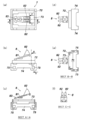
- FIG. 1 shows a base constituting the waterproof and dustproof switch of FIG. 1, (a) is a plan view before cutting, (b) is a front view, (c) is a cross-sectional view along AA, (d) is a right side view, (E) is a BB cross-sectional view, and (f) is a plan view after cutting.
- 1A and 1B show a contact pattern constituting the waterproof and dustproof switch of FIG. 1, wherein FIG. 1A is a plan view, FIG.
- FIG. 1B is a front view
- FIG. 1 shows a lever constituting the waterproof and dustproof switch of FIG. 1, (a) is a plan view, (b) is a right side view, (c) is a front view, (d) is a cross-sectional view along AA, (e)
- FIG. 3 is a front view of a state in which a contact spring piece is mounted.
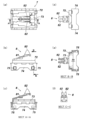
- FIGS. 1A and 1B show a state when the switch case constituting the waterproof and dustproof switch of FIG. 1 is primary molded.
- FIG. 1A is a plan view
- FIG. 1B is a front view
- (e) is a BB cross-sectional view
- (f) is a CC cross-sectional view.
- FIG. 1A is a plan view
- FIG. 1B is a front view
- (e) is a BB cross-sectional view
- (f) is a
- FIG. 2 shows the state of the switch case constituting the waterproof and dustproof switch of FIG. 1 at the time of secondary molding. Is a right side view, and (e) is a BB sectional view.
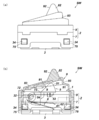
- the state at the time of stillness of the waterproof dustproof switch of Drawing 1 is shown, (a) is an appearance figure and (b) is a sectional view.
- movement of the waterproof dustproof switch of FIG. 1 is shown, (a) is an external view, (b) is sectional drawing.
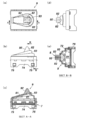
- the external appearance of the waterproof dustproof switch of 2nd Embodiment is shown, (a) is a top view, (b) is a front view.
- FIGS. 10A and 10B show a state of the switch case constituting the waterproof and dustproof switch of FIG.
- FIGS. 10A and 10B show a state of the switch case constituting the waterproof and dustproof switch of FIG. 10 during secondary molding, where FIG. 10A is a plan view, FIG. 10B is a front view, FIG. Is a right side view, and (e) is a BB sectional view.
- the waterproof and dustproof switch SW of the present embodiment is a small switch that can be used as a power switch in an electronic device such as an electronic book terminal or a mobile phone.
- This switch is characterized in that a waterproof and dustproof structure is adopted for the switch case 2 in order to prevent water droplets, dust, dust and the like from entering the internal switch mechanism 1 and the electronic device main body during use.
- the illustrated power switch is merely an example, and the present invention can be used as another switch used in an environment where waterproofness and dustproofness are required.
- the waterproof and dustproof switch SW includes a switch mechanism unit 1 and a switch case 2.
- the switch mechanism 1 switches contacts by the action of an external force (for example, pressing with a finger).
- a lever switch that switches contacts by tilting the lever 5 as an operating body is employed.
- the switch case 2 protects the switch mechanism 1, and in the present embodiment, the switch mechanism 2 is completely sealed by a double structure of the case body 7 and the cover 9.
- FIG. 3 shows the base 3 constituting the switch mechanism unit 1.
- the base 3 is formed of an insulating resin material (polyamide resin in this embodiment), and is provided with a space 31 for housing components inside a flat box-type main body so that it can be mounted on a substrate.
- a concave portion 32 for installing a later-described lever 5 is formed on the front surface and the back surface of the main body, and a pedestal 33 is formed on the inner bottom surface of the main body.
- a locking claw 34 for mounting a switch case 2 described later is provided on the outer wall surface of the main body.
- FIG. 4 shows a contact pattern 4 constituting the switch mechanism unit 1.
- the contact pattern 4 is obtained by punching a conductive metal plate (in this embodiment, a phosphor bronze plate), and has two rows of fixed contacts 41 and 42 arranged at a predetermined interval in the center. ing. Each of the fixed contacts 41, 42 is provided with four connection terminals 43, 43,.
- the contact pattern 4 is insert-molded when the base 3 is molded, so that two rows of fixed contacts 41 and 42 are fixed to the inner bottom surface of the base 3 and connected to the fixed contacts 41 and 42.
- the two rows of fixed contacts 41 and 42 are separated from each other as shown in FIG.
- FIG. 5 shows the lever 5 constituting the switch mechanism 1.
- the lever 5 is formed of an insulating resin material (polyamide resin in this embodiment), and transmits an external force to the operation portion 51 that receives an external force, a holder portion 52 that holds the contact spring piece 6, and the external force to the contact spring piece 6.
- the cam portion 53 is provided.
- the contact spring piece 6 is fitted and fixed to the lever 5 in the holder portion 52 in the accumulated state.
- the contact spring piece 6 is formed by bending a metal piece into a U shape to give elasticity, bifurcating the end portion into two legs, and forming a pair of leg portions, the tips of which are independent movable contacts 61 and 62, respectively. It is.
- the lever 5 to which the contact spring pieces 6 are fixed is supported rotatably by inserting the shaft portion 54 provided on the outer wall surface into the concave portion 33 of the base 3 and using the shaft portion 54 as a fulcrum. .
- the switch case 2 has a double structure composed of a case body 7 molded by primary molding shown in FIG. 6 and a cover 9 molded by secondary molding shown in FIG.
- the case body 7 is made of a hard material having an insulating property (polyamide resin in this embodiment). Molded into a shape.
- the case body 7 is placed on the base 3 to protect the switch mechanism 1.
- a space 71 for housing the lever 5 is provided inside the body, and the lever 5 is inserted through the top plate 72 on the upper surface of the body.
- An opening 73 is formed.
- Mounting pieces 74 for fixing to the base 3 are provided on the front and back surfaces of the main body, and the mounting pieces 74 are formed with locking holes 75 that fit into the locking claws 34 of the base 3.
- a reinforcing rib 8 which is a framework of the cover 9 is provided by the same hard material as the case body 7.
- the reinforcing ribs 8 are arranged in an inclined state with respect to the top plate 72 of the case body 7 as shown in FIGS. 6B and 6C, and the reinforcing ribs 8 and the top plate 72 have elasticity.
- a spring portion 81 is configured. Further, as shown in FIGS. 6D, 6 ⁇ / b> E, and 5 ⁇ / b> F, two rows of protrusions 82 and 82 formed in the same mountain shape as the lever 5 are provided at one end of the reinforcing rib 8.
- the other end of the reinforcing rib 8 is provided with a round hole 83 for securing a contact area with the cover 9 as shown in FIGS.
- the reinforcing rib 8 is provided separately from the case main body 7.
- the reinforcing rib 8 may be connected to the top plate 72 of the case main body 7 and provided integrally.
- the cover 9 is made of an insulating soft material such as an elastomer resin (silicone rubber in the present embodiment).
- the dome shape having a cavity 91 is formed.
- the mold is opened, only the upper mold is replaced with an upper mold for cover molding (with the reinforcing rib 8 set in the mold), and then the mold is clamped. Liquid silicone rubber may be injected into the mold and finally cooled and cured.
- the switch case 2 in which the case body 7 and the cover 9 are integrated is formed by molding the hard material (polyamide resin) and the soft material (silicone rubber) in two colors.
- the switch case 2 molded in two colors is mounted on a base 3 on which a lever 5 is installed.
- the switch case 2 is covered from above the base 3, and the base 3 and the switch case 2 are fixed by hooking the locking claw 34 of the base 3 into the locking hole 75 of the case body 7 as shown in the figure.
- the switch case 2 is formed by integrating a cover 9 covered on the case body 7 by two-color molding, so that the cover 9 is in close contact with the case body 7 so that water drops, dust, etc. enter from the outside. Can be completely shut off.
- the reinforcing rib 8 made of a hard material is joined to the cover 9 made of a soft material at a portion subjected to the action of an external force, the cover 9 has significantly improved performance such as shape retention, durability, and operational stability. improves.
- silicone rubber constituting the cover 9 enters the round hole 83 of the reinforcing rib 8, and as shown in FIGS.
- a protrusion 92 made of silicone rubber that constitutes the cover 9 is also inserted between and bonded to 82. Therefore, a large contact area between the case body 7 and the cover 9 is ensured, and the adhesion between them is further enhanced.
- the reinforcing rib 8 made of a hard material is joined and integrated to the cover 9 made of silicone rubber.
- the protrusion 92 that receives the action of an external force is protected by being sandwiched by a thick protrusion 82 made of a hard material, and thus has excellent durability.
- the cover 9 made of silicone rubber has a stepped step 93, and when pressed with a finger, it becomes a starting point of a dent and is easily deformed, and also has strength, so it is smooth and stable over a long period of time. Operation can be realized.
- the case main body 7 and the reinforcing rib 8 constituting the switch case 2 are separated from each other.
- the case main body 7 and the reinforcing rib 8 can be integrally provided instead.
- the switch case 2 is composed of a case body 7 formed by primary molding shown in FIG. 11 and a cover 9 formed by secondary molding shown in FIG. It has a heavy structure.
- the reinforcing rib 8 is connected to the top plate 72 of the case body 7 made of a hard material (polyamide resin in the present embodiment), and the connecting portion has a resilient spring. Part 81 is configured. Then, as shown in FIG. 12, a soft material such as an elastomer resin (silicone rubber in this embodiment) is heated and melted and injection-molded to form a dome-shaped cover 9 having a hollow portion 91 inside. .
- the switch case 2 in which the case body 7 and the cover 9 are integrated is formed by molding the hard material (polyamide resin) and the soft material (silicone rubber) in two colors.
- the cover 9 since the cover 9 is in close contact with the case body 7 constituting the switch case 2, entry of water droplets or dust from the outside is completely blocked, and the switch mechanism unit 1 is It can be surely protected.
- the case body 7 and the reinforcing rib 8 are connected, and the connecting portion constitutes a leaf spring 81. Therefore, the compression and elastic return operations by the leaf spring 81 are performed smoothly. There is an advantage that stable switch operation with good responsiveness can be realized.
- the lever switch is employed as the switch mechanism unit 1 constituting the waterproof and dustproof switch SW.
- the present invention is not limited to this, and a switch having another structure such as a push switch or a slide switch may be employed.
- the shape and material of the case main body 7 and the cover 9 constituting the switch case 2 are not limited to the above-described embodiments, and the ordinary creation of those skilled in the art within the scope of the technical idea of the present invention. It can be changed appropriately depending on the ability.
- SW Waterproof and dustproof switch 1 ... Switch mechanism 2 ... Switch case 3 ... Base 31 ... Space 32 ... Recess 33 ... Base 34 ... Locking claw 4 ... Contact pattern 41 ... Fixed contact 42 ... Fixed contact 43 ... Connection terminal 5 ... Lever DESCRIPTION OF SYMBOLS 51 ... Operation part 52 ... Holder part 53 ... Cam part 54 ... Shaft part 6 ... Contact spring piece 61 ... Movable contact 62 ... Movable contact 7 ... Case main body 71 ... Space 72 ... Top plate 73 ... Opening part 74 ... Mounting piece 75 ... Locking hole 8 ... Reinforcement rib 81 ... Plate spring part 82 ... Protrusion part 83 ... Round hole 9 ... Cover 91 ... Cavity 92 ... Protrusion part 93 ... Step
Landscapes
- Push-Button Switches (AREA)
- Switches With Compound Operations (AREA)
- Switch Cases, Indication, And Locking (AREA)
- Rotary Switch, Piano Key Switch, And Lever Switch (AREA)
Abstract
Description
1…スイッチ機構部
2…スイッチケース
3…ベース
31…空間
32…凹部
33…台座
34…係止爪
4…接点パターン
41…固定接点
42…固定接点
43…接続端子
5…レバー
51…操作部
52…ホルダ部
53…カム部
54…軸部
6…接点ばね片
61…可動接点
62…可動接点
7…ケース本体
71…空間
72…天板
73…開口部
74…取付片
75…係止孔
8…補強リブ
81…板ばね部
82…突起部
83…丸孔
9…カバー
91…空洞
92…突起部
93…段差 SW: Waterproof and
Claims (5)
- 外力の作用により接点を切り換えるスイッチ機構部と、
前記スイッチ機構部を保護するスイッチケースを備え、
前記スイッチケースは、
前記スイッチ機構部を収容する硬質材料からなるケース本体と、
前記ケース本体に覆い被せた軟質材料からなるカバーにより構成されており、
前記ケース本体と前記カバーが2色成形により一体化されているとともに、前記カバーにおける外力の作用を受ける部分に前記ケース本体と一体又は別体の補強リブが設けられていることを特徴とする防水防塵スイッチ。 A switch mechanism that switches contacts by the action of external force;
A switch case for protecting the switch mechanism,
The switch case is
A case body made of a hard material for accommodating the switch mechanism,
It is composed of a cover made of a soft material that covers the case body,
The case main body and the cover are integrated by two-color molding, and a portion of the cover that receives an external force is provided with a reinforcing rib that is integral with or separate from the case main body. Dust-proof switch. - 前記スイッチケースは、前記ケース本体の天板と当該天板に対して傾斜させた前記補強リブとにより板ばねが形成されていることを特徴とする請求項1に記載の防水防塵スイッチ。 The waterproof and dustproof switch according to claim 1, wherein the switch case includes a plate spring formed by a top plate of the case body and the reinforcing rib inclined with respect to the top plate.
- 前記スイッチケースは、前記カバーに外力が作用したときに、前記補強リブが前記スイッチ機構部の操作体を押圧する位置に配置されていることを特徴とする請求項1又は2に記載の防水防塵スイッチ。 3. The waterproof and dustproof structure according to claim 1, wherein the switch case is disposed at a position where the reinforcing rib presses the operating body of the switch mechanism when an external force is applied to the cover. switch.
- 前記スイッチケースは、前記ケース本体がポリアミド樹脂からなり、前記カバーがシリコーンゴムからなることを特徴とする請求項1~3のいずれか1項に記載の防水防塵スイッチ。 The waterproof and dustproof switch according to any one of claims 1 to 3, wherein the switch body is made of a polyamide resin and the cover is made of silicone rubber.
- 前記スイッチ機構部は、レバーの傾倒動作により接点を切り換えるレバースイッチであることを特徴とする請求項1~4のいずれか1項に記載の防水防塵スイッチ。 The waterproof and dustproof switch according to any one of claims 1 to 4, wherein the switch mechanism unit is a lever switch that switches a contact point by a tilting operation of the lever.
Priority Applications (4)
| Application Number | Priority Date | Filing Date | Title |
|---|---|---|---|
| KR1020147007199A KR101827510B1 (en) | 2011-09-21 | 2012-05-17 | Waterproof and dust protected switch |
| JP2013534610A JP6045114B2 (en) | 2011-09-21 | 2012-05-17 | Waterproof dustproof switch |
| CN201280046307.4A CN103828004B (en) | 2011-09-21 | 2012-05-17 | Water proof and dust proof is switched |
| EP12833210.3A EP2760036A4 (en) | 2011-09-21 | 2012-05-17 | Waterproof and dust protected switch |
Applications Claiming Priority (2)
| Application Number | Priority Date | Filing Date | Title |
|---|---|---|---|
| JP2011-205828 | 2011-09-21 | ||
| JP2011205828 | 2011-09-21 |
Publications (1)
| Publication Number | Publication Date |
|---|---|
| WO2013042403A1 true WO2013042403A1 (en) | 2013-03-28 |
Family
ID=47914184
Family Applications (1)
| Application Number | Title | Priority Date | Filing Date |
|---|---|---|---|
| PCT/JP2012/062586 WO2013042403A1 (en) | 2011-09-21 | 2012-05-17 | Waterproof and dust protected switch |
Country Status (5)
| Country | Link |
|---|---|
| EP (1) | EP2760036A4 (en) |
| JP (1) | JP6045114B2 (en) |
| KR (1) | KR101827510B1 (en) |
| CN (1) | CN103828004B (en) |
| WO (1) | WO2013042403A1 (en) |
Cited By (2)
| Publication number | Priority date | Publication date | Assignee | Title |
|---|---|---|---|---|
| JP2019519881A (en) * | 2016-05-16 | 2019-07-11 | モトローラ ソリューションズ インコーポレイテッドMotorola Solutions, Inc. | Push-to-talk assembly for portable communication devices |
| CN111785555A (en) * | 2020-07-29 | 2020-10-16 | 中国科学院沈阳自动化研究所 | Underwater pressing type switch device for full sea depth |
Families Citing this family (3)
| Publication number | Priority date | Publication date | Assignee | Title |
|---|---|---|---|---|
| GB2531377B (en) * | 2015-05-14 | 2017-02-01 | Wheely-Safe Ltd | Wheel loosening sensor |
| KR101925845B1 (en) * | 2018-05-23 | 2018-12-06 | (주)유프랜드 | Safety belt buckle |
| CN109962042B (en) * | 2019-04-16 | 2020-07-17 | 常州信息职业技术学院 | Integrated circuit packaging structure |
Citations (5)
| Publication number | Priority date | Publication date | Assignee | Title |
|---|---|---|---|---|
| JPS4715412Y1 (en) * | 1968-04-01 | 1972-05-31 | ||
| JPS56100828U (en) * | 1979-12-29 | 1981-08-08 | ||
| JPH0499643U (en) * | 1991-01-24 | 1992-08-28 | ||
| JPH091678A (en) * | 1995-06-15 | 1997-01-07 | Shin Etsu Polymer Co Ltd | Push-button switch device and housing therefor |
| JP2005209527A (en) | 2004-01-23 | 2005-08-04 | Mic Electron Co | Waterproof switch and its manufacturing method |
Family Cites Families (10)
| Publication number | Priority date | Publication date | Assignee | Title |
|---|---|---|---|---|
| JPS5042372Y1 (en) * | 1970-12-11 | 1975-12-02 | ||
| JPS6427928U (en) * | 1987-08-12 | 1989-02-17 | ||
| US5063277A (en) * | 1989-06-28 | 1991-11-05 | Daiichi Denso Buhin Co., Ltd. | Waterproof and dustproof push switch |
| JPH0478725U (en) * | 1990-11-20 | 1992-07-09 | ||
| JPH0715412Y2 (en) * | 1991-07-12 | 1995-04-12 | 康彦 西村 | Fishing hook |
| US5380968A (en) * | 1993-09-29 | 1995-01-10 | A.P.M. Hexseal Corporation | Protective cover for switches |
| JP2001057127A (en) * | 1999-08-20 | 2001-02-27 | Nec Corp | Drip-resistant and dust-resistant structure for key switch device |
| JP4204372B2 (en) * | 2003-04-17 | 2009-01-07 | 株式会社東郷製作所 | Secondary molded products for switches |
| JP4273867B2 (en) | 2003-08-05 | 2009-06-03 | パナソニック株式会社 | Vehicle switch |
| JP4323363B2 (en) * | 2004-04-01 | 2009-09-02 | アルプス電気株式会社 | Switch device |
-
2012
- 2012-05-17 EP EP12833210.3A patent/EP2760036A4/en not_active Withdrawn
- 2012-05-17 WO PCT/JP2012/062586 patent/WO2013042403A1/en active Application Filing
- 2012-05-17 CN CN201280046307.4A patent/CN103828004B/en active Active
- 2012-05-17 JP JP2013534610A patent/JP6045114B2/en active Active
- 2012-05-17 KR KR1020147007199A patent/KR101827510B1/en active IP Right Grant
Patent Citations (5)
| Publication number | Priority date | Publication date | Assignee | Title |
|---|---|---|---|---|
| JPS4715412Y1 (en) * | 1968-04-01 | 1972-05-31 | ||
| JPS56100828U (en) * | 1979-12-29 | 1981-08-08 | ||
| JPH0499643U (en) * | 1991-01-24 | 1992-08-28 | ||
| JPH091678A (en) * | 1995-06-15 | 1997-01-07 | Shin Etsu Polymer Co Ltd | Push-button switch device and housing therefor |
| JP2005209527A (en) | 2004-01-23 | 2005-08-04 | Mic Electron Co | Waterproof switch and its manufacturing method |
Non-Patent Citations (1)
| Title |
|---|
| See also references of EP2760036A4 * |
Cited By (3)
| Publication number | Priority date | Publication date | Assignee | Title |
|---|---|---|---|---|
| JP2019519881A (en) * | 2016-05-16 | 2019-07-11 | モトローラ ソリューションズ インコーポレイテッドMotorola Solutions, Inc. | Push-to-talk assembly for portable communication devices |
| US10770242B2 (en) | 2016-05-16 | 2020-09-08 | Motorola Solutions, Inc. | Button assembly for a portable communication device |
| CN111785555A (en) * | 2020-07-29 | 2020-10-16 | 中国科学院沈阳自动化研究所 | Underwater pressing type switch device for full sea depth |
Also Published As
| Publication number | Publication date |
|---|---|
| CN103828004B (en) | 2017-09-22 |
| JPWO2013042403A1 (en) | 2015-03-26 |
| KR101827510B1 (en) | 2018-02-08 |
| JP6045114B2 (en) | 2016-12-14 |
| EP2760036A4 (en) | 2015-06-24 |
| KR20140064881A (en) | 2014-05-28 |
| EP2760036A1 (en) | 2014-07-30 |
| CN103828004A (en) | 2014-05-28 |
Similar Documents
| Publication | Publication Date | Title |
|---|---|---|
| JP4716988B2 (en) | Electrical switch | |
| JP6045114B2 (en) | Waterproof dustproof switch | |
| JP2012028175A (en) | Push-button switch structure and electronic apparatus provided with the same | |
| JP2014532973A5 (en) | ||
| US20110308925A1 (en) | Push switch | |
| US6313420B1 (en) | Slide switch | |
| JP4730171B2 (en) | Push / Slide switch | |
| JP4323363B2 (en) | Switch device | |
| JP4607697B2 (en) | Waterproof pushbutton switch device | |
| JP5284883B2 (en) | Push-button switch | |
| JP2009134950A (en) | Slide switch with push switch | |
| KR101789925B1 (en) | Push button switch assembly and manufacturing method thereof | |
| US11462370B2 (en) | Push switch | |
| JP4649393B2 (en) | Horizontal push type 2-stage operation switch | |
| JP2005019112A (en) | Push-button switch | |
| JP2009134951A (en) | Slide switch with two-stage push switch | |
| JP2009134952A (en) | Slide switch with push-switch | |
| JP4044395B2 (en) | Push button switch | |
| CN215344727U (en) | Shell subassembly and have its thermal imaging camera | |
| US11862425B2 (en) | Switch device, and opening and closing detection device | |
| JP2013225426A (en) | Switch structure of substrate | |
| JP2011113817A (en) | Dust-protective rocker switch | |
| JP3346106B2 (en) | Push switch | |
| KR101426490B1 (en) | Slim Type Push Switch Device | |
| JP2005093347A (en) | Push-button switch |
Legal Events
| Date | Code | Title | Description |
|---|---|---|---|
| 121 | Ep: the epo has been informed by wipo that ep was designated in this application |
Ref document number: 12833210 Country of ref document: EP Kind code of ref document: A1 |
|
| ENP | Entry into the national phase |
Ref document number: 20147007199 Country of ref document: KR Kind code of ref document: A |
|
| ENP | Entry into the national phase |
Ref document number: 2013534610 Country of ref document: JP Kind code of ref document: A |
|
| NENP | Non-entry into the national phase |
Ref country code: DE |
|
| REEP | Request for entry into the european phase |
Ref document number: 2012833210 Country of ref document: EP |
|
| WWE | Wipo information: entry into national phase |
Ref document number: 2012833210 Country of ref document: EP |