WO2013042205A1 - Pedestrian action prediction device and pedestrian action prediction method - Google Patents
Pedestrian action prediction device and pedestrian action prediction method Download PDFInfo
- Publication number
- WO2013042205A1 WO2013042205A1 PCT/JP2011/071398 JP2011071398W WO2013042205A1 WO 2013042205 A1 WO2013042205 A1 WO 2013042205A1 JP 2011071398 W JP2011071398 W JP 2011071398W WO 2013042205 A1 WO2013042205 A1 WO 2013042205A1
- Authority
- WO
- WIPO (PCT)
- Prior art keywords
- pedestrian
- shape information
- change
- motion estimation
- acquired
- Prior art date
Links
Images


Classifications
-
- G—PHYSICS
- G06—COMPUTING; CALCULATING OR COUNTING
- G06V—IMAGE OR VIDEO RECOGNITION OR UNDERSTANDING
- G06V40/00—Recognition of biometric, human-related or animal-related patterns in image or video data
- G06V40/10—Human or animal bodies, e.g. vehicle occupants or pedestrians; Body parts, e.g. hands
- G06V40/103—Static body considered as a whole, e.g. static pedestrian or occupant recognition
-
- G—PHYSICS
- G06—COMPUTING; CALCULATING OR COUNTING
- G06V—IMAGE OR VIDEO RECOGNITION OR UNDERSTANDING
- G06V20/00—Scenes; Scene-specific elements
- G06V20/50—Context or environment of the image
- G06V20/56—Context or environment of the image exterior to a vehicle by using sensors mounted on the vehicle
- G06V20/58—Recognition of moving objects or obstacles, e.g. vehicles or pedestrians; Recognition of traffic objects, e.g. traffic signs, traffic lights or roads
-
- G—PHYSICS
- G06—COMPUTING; CALCULATING OR COUNTING
- G06V—IMAGE OR VIDEO RECOGNITION OR UNDERSTANDING
- G06V40/00—Recognition of biometric, human-related or animal-related patterns in image or video data
- G06V40/20—Movements or behaviour, e.g. gesture recognition
- G06V40/23—Recognition of whole body movements, e.g. for sport training
- G06V40/25—Recognition of walking or running movements, e.g. gait recognition
-
- G—PHYSICS
- G08—SIGNALLING
- G08G—TRAFFIC CONTROL SYSTEMS
- G08G1/00—Traffic control systems for road vehicles
- G08G1/07—Controlling traffic signals
- G08G1/08—Controlling traffic signals according to detected number or speed of vehicles
-
- G—PHYSICS
- G08—SIGNALLING
- G08G—TRAFFIC CONTROL SYSTEMS
- G08G1/00—Traffic control systems for road vehicles
- G08G1/16—Anti-collision systems
- G08G1/166—Anti-collision systems for active traffic, e.g. moving vehicles, pedestrians, bikes
-
- B—PERFORMING OPERATIONS; TRANSPORTING
- B60—VEHICLES IN GENERAL
- B60W—CONJOINT CONTROL OF VEHICLE SUB-UNITS OF DIFFERENT TYPE OR DIFFERENT FUNCTION; CONTROL SYSTEMS SPECIALLY ADAPTED FOR HYBRID VEHICLES; ROAD VEHICLE DRIVE CONTROL SYSTEMS FOR PURPOSES NOT RELATED TO THE CONTROL OF A PARTICULAR SUB-UNIT
- B60W2420/00—Indexing codes relating to the type of sensors based on the principle of their operation
- B60W2420/40—Photo or light sensitive means, e.g. infrared sensors
-
- B—PERFORMING OPERATIONS; TRANSPORTING
- B60—VEHICLES IN GENERAL
- B60W—CONJOINT CONTROL OF VEHICLE SUB-UNITS OF DIFFERENT TYPE OR DIFFERENT FUNCTION; CONTROL SYSTEMS SPECIALLY ADAPTED FOR HYBRID VEHICLES; ROAD VEHICLE DRIVE CONTROL SYSTEMS FOR PURPOSES NOT RELATED TO THE CONTROL OF A PARTICULAR SUB-UNIT
- B60W2554/00—Input parameters relating to objects
Definitions
- the present invention relates to a pedestrian behavior prediction device and a pedestrian behavior prediction method.
- a feature point is extracted from an image captured by a camera, movement information including a movement speed and / or a movement direction of the extracted feature point is calculated, and the movement of the calculated feature point is calculated.
- the target area including the moving target three-dimensional object is extracted from the captured image, and the movement information regarding the extracted target area is compared with the movement information regarding the comparison area set around the target area.
- the pedestrian detection apparatus which determines whether the target solid object contained in the target area extracted based on the comparison result of the movement information is a pedestrian is disclosed.
- Patent Document 2 the time series change of the position and movement speed of the pedestrian existing in front of the host vehicle and the peripheral information are acquired, the time series change of the acquired position and movement speed, and the pedestrian Compared with the time-series change pattern of the position and moving speed when jumping out on the roadway, by comparing the acquired surrounding information with the peripheral information obtained in advance when the pedestrian jumps out on the roadway, There has been disclosed a pedestrian jump prediction device that predicts whether or not a pedestrian jumps out on a traveling roadway.
- Patent Documents 1 and 2 etc. has not been able to predict pedestrian behavior around the vehicle quickly and accurately.
- the pedestrian detection device described in Patent Literature 1 can capture a pedestrian's movement and can predict a pedestrian's linear jump-out motion (continuous motion) that can be linearly predicted as an extension of the movement, The movement (discontinuous movement) jumping to the road after turning to the direction could not be predicted.
- the pedestrian pop-out prediction device described in Patent Document 2 cannot secure sufficient accuracy of environment recognition, and has room for improvement.
- This invention is made in view of said situation, Comprising: It aims at providing the pedestrian action prediction apparatus and pedestrian action prediction method which can predict the action of the pedestrian around a vehicle rapidly and correctly. .
- the pedestrian behavior prediction device of the present invention is acquired from a pedestrian detection unit that detects a pedestrian from a captured image and extracts a partial image including the pedestrian, and the partial image extracted by the pedestrian detection unit.
- An operation change for detecting a change in the movement of the pedestrian by storing the shape information of the pedestrian and comparing the shape information before a predetermined time with the current shape information using the accumulated shape information.
- Discontinuous motion estimation information indicating the discontinuous motion of the pedestrian that occurs following the change in the motion of the pedestrian when the motion of the pedestrian is detected by the detection means and the motion change detection means.
- Discontinuous motion estimation means acquired from storage means, and behavior prediction means for predicting the behavior of the pedestrian using the discontinuous motion estimation information acquired by the discontinuous motion estimation means, That.
- the motion change detection unit acquires a feature amount distribution representing the shape information of the pedestrian acquired from the partial image extracted by the pedestrian detection unit, and the shape information represented by the acquired feature amount distribution Is stored, the normalized shape information is accumulated, and the accumulated shape information is used to compare the shape information of a predetermined time ago with the current shape information, thereby changing the movement of the pedestrian. It is preferable to detect.
- the discontinuous motion estimation means calculates an optical flow of the captured image and acquires the discontinuous motion estimation information using the optical flow when the motion change detection means detects a change in motion of the pedestrian. It is preferable to do.
- the pedestrian detection unit acquires the position of the pedestrian on the captured image, and the pedestrian behavior prediction device performs the walking based on the history of the position of the pedestrian acquired by the pedestrian detection unit.
- Continuous motion estimation means for generating continuous motion estimation information indicating continuous motion of the pedestrian that occurs following the movement of the person's position, and the behavior prediction means is generated by the continuous motion estimation means It is preferable to predict the behavior of the pedestrian based on continuous motion estimation information.
- the discontinuous motion estimation information and the continuous motion estimation information include at least one of a moving direction and a moving speed of the pedestrian.
- the motion change detecting means uses a predetermined feature amount, and obtains the feature amount distribution representing the shape information of the pedestrian from the partial image extracted by the pedestrian detecting means, Normalizing means for normalizing the feature quantity distribution obtained by the shape information obtaining means to obtain a probability distribution corresponding to the feature quantity distribution, and shape information accumulating means for accumulating the probability distribution obtained by the normalizing means. And using a predetermined scale, calculating a difference between the probability distribution before the predetermined time accumulated by the shape information accumulating means and the current probability distribution, and when the calculated difference is larger than a predetermined threshold, It is preferable that the apparatus further includes a change detection unit that detects a change in the movement of the pedestrian.
- the pedestrian behavior prediction method of the present invention is acquired from a pedestrian detection step of detecting a pedestrian from a captured image and extracting a partial image including the pedestrian, and the partial image extracted in the pedestrian detection step.
- An operation for detecting a change in the movement of the pedestrian by comparing the shape information of a predetermined time ago with the current shape information using the accumulated shape information.
- Discontinuous motion estimation indicating a discontinuous motion of the pedestrian that occurs following a change in the motion of the pedestrian when a change in the motion of the pedestrian is detected in the change detection step and the motion change detection step
- a discontinuous motion estimation step for acquiring information from a storage means; and a behavior prediction step for predicting the behavior of the pedestrian using the discontinuous motion estimation information acquired in the discontinuous motion estimation step; Characterized in that it comprises a.
- a feature amount distribution representing the shape information of the pedestrian acquired from the partial image extracted in the pedestrian detection step is acquired, and the shape represented by the acquired feature amount distribution Normalizing information, accumulating the normalized shape information, and using the accumulated shape information to compare the shape information before a predetermined time with the current shape information, thereby changing the movement of the pedestrian Is preferably detected.
- the discontinuous motion estimation step when a change in the motion of the pedestrian is detected in the motion change detection step, an optical flow of the captured image is calculated, and the discontinuous motion estimation information is calculated using the optical flow. It is preferable to obtain.
- the pedestrian detection step the position of the pedestrian on the captured image is acquired, and the pedestrian behavior prediction method is based on a history of the position of the pedestrian acquired in the pedestrian detection step.
- a continuous motion estimation step for generating continuous motion estimation information indicating a continuous motion of the pedestrian that occurs following the movement of the position of the pedestrian, and the continuous motion estimation information generated in the continuous motion estimation step It is preferable to predict the behavior of the pedestrian based on the above.
- the present invention has the effect of being able to quickly and accurately predict the behavior of pedestrians around the vehicle.
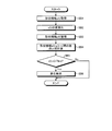
- FIG. 1 is a block diagram showing an example of a pedestrian behavior prediction apparatus according to the present invention.
- FIG. 2 is a flowchart illustrating an example of a pedestrian behavior prediction process according to the first embodiment.
- FIG. 3 is a flowchart illustrating an example of the operation change detection process according to the first embodiment.
- FIG. 4 is a diagram illustrating an example of a motion change detection graph according to the first embodiment.
- FIG. 5 is a flowchart illustrating an example of a pedestrian behavior prediction process according to the second embodiment.
- FIG. 1 is a block diagram showing an example of the configuration of a pedestrian behavior prediction apparatus according to the present invention.
- the pedestrian behavior prediction apparatus 1 is configured using, for example, an automobile control computer mounted on a vehicle, and communicates with a camera 2 and a notification unit 4 mounted on the vehicle. Connected as possible.
- the camera 2 is a device that captures the periphery of the host vehicle and generates image data (captured image) in which the periphery of the host vehicle is projected.
- the camera 2 is an imaging means such as a CCD camera or a CMOS camera that can image in the visible light region or the infrared region, for example.
- the camera 2 is installed at an arbitrary position capable of capturing an image of the vehicle periphery such as the front, side, and rear of the vehicle.
- the pedestrian behavior prediction apparatus 1 may be used in combination with the camera 2, a stereo camera, an imaging laser radar, and the like.
- the notification means 4 is a display that outputs image information, a speaker that outputs audio information, or the like. In the present embodiment, the notification means 4 is used to notify the driver of a danger when a dangerous action of a pedestrian around the vehicle occurs while the driver is driving the vehicle.
- the pedestrian behavior prediction device 1 includes a control unit 12 and a storage unit 14.
- the control unit 12 controls the pedestrian behavior prediction apparatus 1 in an integrated manner, and is, for example, a CPU (Central Processing Unit).
- the storage unit 14 is for storing data, and is, for example, a RAM (Random Access Memory), a ROM (Read Only Memory), or a hard disk.
- the storage unit 14 includes a shape information storage unit 14a and a discontinuous motion estimation information storage unit 14b.
- the shape information storage unit 14 a is shape information storage means for storing pedestrian shape information extracted from the captured image captured by the camera 2.
- the shape information is data indicating the feature amount of the shape of the pedestrian.
- the feature amount is not limited to this, but the first feature amount that uses the luminance of the captured image itself, the second feature amount that uses the edge of the captured image, and the third feature amount that uses the color of the captured image. At least one of them.
- the first feature amount includes, for example, at least one of luminance, luminance PCA, Hu moment, LBP, Haarlike feature, and position.
- the second feature amount includes, for example, at least one of SIFT, PCA, SURF, GLOH, shape context, HOG, CoHOG, FIND, and edge.
- the third feature amount includes, for example, at least one of RGB and Lab.
- the discontinuous motion estimation information storage unit 14b is a discontinuous motion indicating image data at the time when the pedestrian's motion has changed and the discontinuous motion of the pedestrian that occurs following the change of the pedestrian's motion.
- Discontinuous motion estimation information storage means for storing estimated information in association with each other.
- the change in the pedestrian's movement means a change in the dangerous movement of the pedestrian in the traffic environment, and includes a change in the shape at the start of the pedestrian's movement change, that is, a change in the feature amount of the image.
- the change of the pedestrian's movement includes, but is not limited to, for example, a pedestrian's sudden turning operation, a pedestrian's arm or leg's sudden swinging movement, and the like.
- discontinuous movement for example, the movement of the pedestrian moving along the sidewalk suddenly changes the direction of travel and enters the roadside, the pedestrian moves at a low speed along the sidewalk. An operation that suddenly moves at a high speed from a running state, an operation that suddenly starts moving from a state where a pedestrian is stopped, and the like.
- the discontinuous motion estimation information includes at least one of the moving direction and moving speed of the pedestrian.
- data stored in the discontinuous motion estimation information storage unit 14b is stored in advance by the pedestrian behavior prediction device 1.
- the pedestrian behavior prediction device 1 includes the image data at the time when a change in the pedestrian's motion is detected and the discontinuous motion that the pedestrian took after the change in the pedestrian's motion. Are stored in the discontinuous motion estimation information storage unit 14b in association with each other.
- the pedestrian behavior prediction device 1 when the pedestrian is moving along the left sidewalk of the roadway, the pedestrian behavior prediction device 1 includes the image data at the time when the pedestrian's sudden right direction change operation is detected, and the pedestrian's A vector indicating a moving direction and a moving speed representing an action in which a pedestrian enters the road after a sudden right direction changing action is associated with each other and stored in the discontinuous action estimation information storage unit 14b. That is, the discontinuous motion estimation information storage unit 14b stores in advance, as discontinuous motion estimation information, a pedestrian's motion in a dangerous direction (in this case, the right direction) in which the pedestrian suddenly jumps out from the sidewalk to the roadway side. is doing.
- the pedestrian behavior prediction device 1 includes the image data at the time when the pedestrian's sudden leftward movement operation is detected, and the pedestrian moves to the building side after the pedestrian's sudden leftward movement operation.
- the discontinuous motion estimation information storage unit 14b stores in advance, as discontinuous motion estimation information, a pedestrian's motion in a safe direction (in this case, the left direction) that the pedestrian suddenly enters the building from the sidewalk. ing.
- the discontinuous motion estimation information storage unit 14b is configured as a knowledge-based database that stores data acquired and accumulated in advance by the pedestrian behavior prediction device 1.
- the pedestrian behavior prediction apparatus 1 may update data stored in the discontinuous motion estimation information storage unit 14b by online learning.
- the pedestrian behavior prediction device 1 continuously stores image data for a predetermined time from the time when a change in the pedestrian's motion is detected, analyzes the image data group, and analyzes the pedestrian's motion. Data may be updated by predicting discontinuous movements taken by pedestrians after changes.
- the control unit 12 includes a pedestrian detection unit 12a, a motion change detection unit 12b, a discontinuous motion estimation unit 12g, a continuous motion estimation unit 12h, and a behavior prediction unit 12i.
- the motion change detection unit 12b further includes a shape information acquisition unit 12c, a normalization unit 12d, a shape information storage unit 12e, and a change detection unit 12f.
- the pedestrian detection unit 12a is pedestrian detection means for detecting a pedestrian from a captured image.
- the pedestrian detection unit 12a detects a pedestrian by performing pattern matching or the like using data indicating an outline of the shape of the pedestrian stored in the storage unit 14 in advance.
- the pedestrian detection unit 12a extracts a partial image including a pedestrian from the captured image.
- the pedestrian detection part 12a acquires the position of the pedestrian on a captured image.
- the position of the pedestrian is preferably three-dimensional relative coordinates or absolute coordinates with respect to the host vehicle.
- the motion change detection unit 12b accumulates pedestrian shape information acquired from the partial image extracted by the pedestrian detection unit 12a, and uses the accumulated shape information to obtain shape information for a predetermined time and current shape information. It is a motion change detection means for detecting a change in the motion of a pedestrian by comparing.
- the motion change detection unit 12b acquires a feature amount distribution representing the shape information of the pedestrian acquired from the partial image extracted by the pedestrian detection unit 12a, and obtains the shape information represented by the acquired feature amount distribution. Normalized shape information may be accumulated, and the accumulated shape information may be used to detect a change in the pedestrian's movement by comparing the shape information before a predetermined time with the current shape information.
- the motion change detection unit 12b detects a pedestrian motion change through the processing of the shape information acquisition unit 12c, the normalization unit 12d, the shape information storage unit 12e, and the change detection unit 12f.
- the shape information acquisition unit 12c is a shape information acquisition unit that acquires pedestrian shape information from the partial image extracted by the pedestrian detection unit 12a. Specifically, the shape information acquisition unit 12c acquires a feature amount distribution representing pedestrian shape information from the partial image extracted by the pedestrian detection unit 12a using a predetermined feature amount.
- the predetermined feature amount is a feature amount that can be expressed as a probability distribution, and includes at least one of the first feature amount, the second feature amount, and the third feature amount.
- the normalization unit 12d is a normalization unit that normalizes the shape information acquired by the shape information acquisition unit 12c. Specifically, the normalization unit 12d normalizes the feature amount distribution acquired by the shape information acquisition unit 12c, and acquires a probability distribution corresponding to the feature amount distribution.
- the shape information storage unit 12e is shape information storage means for storing the shape information normalized by the normalization unit 12d. Specifically, the shape information accumulation unit 12e accumulates the probability distribution acquired by the normalization unit 12d. In other words, the shape information storage unit 12e stores the normalized shape information (that is, probability distribution) in the shape information storage unit 14a. In the present embodiment, the shape information accumulation unit 12e may accumulate the feature amount distribution before normalization acquired by the shape information acquisition unit 12c.
- the change detection unit 12f uses the normalized shape information accumulated by the shape information accumulation unit 12e, that is, the normalized shape information stored in the shape information storage unit 14a, It is a change detection means for detecting a change in the movement of the pedestrian by comparing with the current shape information. Specifically, the change detection unit 12f calculates a difference between the probability distribution before a predetermined time and the current probability distribution stored in the shape information storage unit 14a by the shape information storage unit 12e using a predetermined scale. If the calculated difference is greater than a predetermined threshold, a change in pedestrian motion is detected.
- the predetermined scale is a scale for measuring a difference between probability distributions by distance or pseudorange.
- the distance includes, but is not limited to, Lp norm, for example, L1 norm (Manhattan distance), L2 norm (Euclidean distance), L infinity norm (uniform norm), and the like.
- the distance may include a Mahalanobis distance. When using this Mahalanobis distance, it is preferable to create a distribution from a plurality of past vectors p (t).
- the distance may include a Hamming distance. When this hamming distance is used, it is preferable to discretize numerical values to some extent.
- the pseudorange includes, but is not limited to, a Kullback-Leibler divergence (hereinafter referred to as a KL information amount).
- the KL information amount is a measure for measuring the difference between the two probability distributions P and Q, and is well known in the field of information theory.
- the change detection unit 12f when accumulating the feature amount distribution before normalization by the shape information accumulation unit 12e, and the current feature amount distribution stored in the shape information storage unit 14a and the current Normalize each feature quantity distribution to obtain a feature quantity distribution before the predetermined time period and a probability distribution corresponding to the current feature quantity distribution, respectively, and use the predetermined scale to obtain the acquired probability distribution before the predetermined time period.
- a difference from the current probability distribution may be calculated, and when the calculated difference is greater than a predetermined threshold, a change in pedestrian motion may be detected.
- the discontinuous motion estimation unit 12g indicates the discontinuous motion indicating the discontinuous motion of the pedestrian that occurs following the change in the motion of the pedestrian when the motion change detection unit 12b detects the change in the motion of the pedestrian.
- This is discontinuous motion estimation means for acquiring estimated information from the discontinuous motion estimation information storage unit 14b.
- the discontinuous motion estimation unit 12g when detecting a change in the pedestrian's motion by the motion change detection unit 12b, previously corresponds to the image data at the time when the change in the pedestrian's motion is detected.
- the image data stored in the continuous motion estimation information storage unit 14b is searched by pattern matching or the like. Then, the discontinuous motion estimation unit 12g acquires discontinuous motion estimation information associated with the searched image data in advance from the discontinuous motion estimation information storage unit 14b.
- the discontinuous motion estimation information includes at least one of the moving direction and the moving speed of the pedestrian.
- the discontinuous motion estimation unit 12g calculates the optical flow of the captured image and acquires the discontinuous motion estimation information using the optical flow when the motion change detection unit 12b detects a change in the motion of the pedestrian. May be. Specifically, the discontinuous motion estimation unit 12g determines whether the pedestrian on the captured image is based on the correlation between the partial image including the pedestrian and the background image around the pedestrian from the temporally continuous captured images. A vector (that is, optical flow) indicating in which direction it is moving is calculated. And the discontinuous motion estimation part 12g acquires the discontinuous motion estimation information which shows a pedestrian's moving direction and moving speed using the calculated optical flow.
- the continuous motion estimation unit 12h is based on the pedestrian position history acquired by the pedestrian detection unit 12a, and indicates continuous motion estimation information indicating the continuous motion of the pedestrian that occurs following the movement of the pedestrian position. Is a continuous motion estimation means for generating.
- movement the operation
- the continuous motion estimation information includes at least one of the moving direction and the moving speed of the pedestrian.
- the continuous motion estimation unit 12h is configured to perform a continuous motion (for example, a motion in which the pedestrian moves continuously, a motion in which the pedestrian moves from a moving state, and a motion in which the pedestrian decelerates) by linear prediction.
- the continuous motion estimation information indicating is generated.
- the behavior prediction unit 12i is a behavior prediction unit that predicts a pedestrian's behavior using the discontinuous motion estimation information acquired by the discontinuous motion estimation unit 12g. For example, when the pedestrian is moving along the sidewalk on the left side of the roadway, the behavior predicting unit 12i is acquired by the discontinuous motion estimating unit 12g, and then the pedestrian has a sudden right turn operation. A pedestrian's action is predicted using the vector (namely, discontinuous motion estimation information) which shows the moving direction and moving speed showing the operation
- a dangerous direction in this case, the right direction
- the behavior prediction unit 12i is a vector indicating the movement direction and the movement speed representing the movement of the pedestrian moving to the building side after the pedestrian's sudden leftward movement operation acquired by the discontinuous movement estimation unit 12g. (Ie, discontinuous motion estimation information) is used to predict pedestrian behavior.
- the behavior predicting unit 12i predicts the pedestrian's movement in a safe direction (in this case, the left direction) that the pedestrian suddenly enters the building from the sidewalk as the pedestrian's behavior.
- the behavior prediction unit 12i may predict the behavior of the pedestrian based on the continuous motion estimation information generated by the continuous motion estimation unit 12h.
- the behavior predicting unit 12i performs the pedestrian's linear jump-out motion that can be linearly predicted as an extension of the movement. Predict as an action.
- the behavior prediction unit 12i may predict, for example, a course indicating when and where the user is as a pedestrian behavior based on the continuous motion estimation information or the discontinuous motion estimation information.
- the pedestrian behavior prediction process executed in the pedestrian behavior prediction apparatus 1 will be described in the order of the first embodiment and the second embodiment.
- the SIFT feature amount is described as an example of the feature amount indicating the shape of the pedestrian, but is not limited thereto.
- the KL information amount will be described as an example as a scale for measuring the difference between the probability distributions P and Q, it is not limited to this.
- Embodiment 1 A pedestrian behavior prediction process according to the first embodiment will be described with reference to FIGS.
- FIG. 2 is a flowchart illustrating an example of a pedestrian behavior prediction process according to the first embodiment.
- FIG. 3 is a flowchart illustrating an example of the operation change detection process according to the first embodiment.
- FIG. 4 is a diagram illustrating an example of a motion change detection graph according to the first embodiment.
- the pedestrian behavior prediction process is repeatedly executed while the driver is driving the vehicle.
- the control unit 12 of the pedestrian behavior prediction apparatus 1 acquires a captured image in which the periphery of the host vehicle is projected from the camera 2 (step SA1).
- the pedestrian detection unit 12a of the pedestrian behavior prediction apparatus 1 detects a pedestrian from the captured image acquired in step SA1 (step SA2). For example, the pedestrian detection unit 12a detects an object by performing pattern matching or the like using data indicating the outline of the shape of the pedestrian stored in the storage unit 14 in advance.
- step SA3 determines whether or not a pedestrian is detected in step SA2 (step SA3).
- step SA3: Yes determines with the control part 12 having detected the pedestrian by step SA3
- step SA7 it progresses to the process of following step SA4 and step SA7. That is, when it is determined that the pedestrian has been detected in step SA3, the control unit 12 executes the processes shown in steps SA4 to SA6 and the processes shown in steps SA7 to SA11 in parallel.
- step SA3 determines with the control part 12 not detecting the pedestrian by step SA3 (step SA3: No)
- a pedestrian action prediction process is complete
- step SA3 when it is determined that the pedestrian is detected in step SA3 (step SA3: Yes), the pedestrian detection unit 12a of the pedestrian behavior prediction apparatus 1 acquires the position of the pedestrian on the captured image (step SA4).
- the pedestrian detection unit 12a acquires three-dimensional relative coordinates or absolute coordinates with respect to the host vehicle as the position of the pedestrian.
- the continuous motion estimation unit 12h of the pedestrian behavior prediction device 1 is generated following the movement of the position of the pedestrian based on the history of the position of the pedestrian acquired by the pedestrian detection unit 12a in step SA4.
- Continuous motion estimation information indicating the continuous motion of the pedestrian is generated (step SA5).
- movement the operation
- the continuous motion estimation information includes at least one of the moving direction and the moving speed of the pedestrian.
- the continuous motion estimation unit 12h is configured to perform a continuous motion (for example, a motion in which the pedestrian moves continuously, a motion in which the pedestrian moves from a moving state, and a motion in which the pedestrian decelerates) by linear prediction.
- the continuous motion estimation information indicating is generated.
- the behavior prediction unit 12i of the pedestrian behavior prediction apparatus 1 predicts the pedestrian behavior using the continuous motion estimation information generated by the continuous motion estimation unit 12h in Step SA5 (Step SA6). For example, when the pedestrian is moving linearly from the sidewalk toward the roadway at a constant speed, the behavior predicting unit 12i performs the pedestrian's linear jump-out motion that can be linearly predicted as an extension of the movement. Predict as an action. Thereafter, the pedestrian behavior prediction process is terminated.
- step SA3 when the pedestrian detection unit 12a of the pedestrian behavior prediction apparatus 1 determines that a pedestrian has been detected in step SA3 (step SA3: Yes), the partial image including the pedestrian from the captured image. Is extracted (step SA7).
- the motion change detection unit 12b of the pedestrian behavior prediction apparatus 1 normalizes the pedestrian shape information acquired from the partial image extracted by the pedestrian detection unit 12a in step SA7, and accumulates the normalized shape information. Then, by using the accumulated shape information, a change in the pedestrian's motion is detected by comparing the shape information before a predetermined time with the current shape information (step SA8).
- the change of the pedestrian's movement means a change of the pedestrian's dangerous movement in the traffic environment, and includes a change of the shape at the start of the movement change of the pedestrian, that is, a change of the feature amount of the image.
- the change of the pedestrian's movement includes, but is not limited to, for example, a pedestrian's sudden turning operation, a pedestrian's arm or leg's sudden swinging movement, and the like.
- the motion change detection unit 12b detects a change in the motion of the pedestrian by the processing of the shape information acquisition unit 12c, the normalization unit 12d, the shape information storage unit 12e, and the change detection unit 12f. To do.
- the shape information acquisition unit 12c of the pedestrian behavior prediction apparatus 1 acquires pedestrian shape information from the partial image extracted by the pedestrian detection unit 12a in step SA7 of FIG. 2 (step SB1). .
- the shape information acquisition unit 12c calculates the SIFT feature value as a feature value distribution v (t) representing the shape information of the pedestrian from the partial image extracted by the pedestrian detection unit 12a in step SA7 in FIG. Perform the calculation.
- the SIFT feature value is well known in the field of image recognition and the like as a feature value representing a shape.
- the SIFT feature value can be expressed as a probability distribution because it can be expressed in a histogram which edge of the captured image including the object is distributed in which direction.
- the normalization unit 12d of the pedestrian behavior prediction apparatus 1 normalizes the L1 norm of the feature amount distribution v (t) acquired in step SB1 to 1 as shown in the following mathematical formula (1), and features A quantity (probability distribution) p (t) is acquired (step SB2).
- the shape information storage unit 12e of the pedestrian behavior prediction apparatus 1 stores the shape information acquired in step SB2 in the shape information storage unit 14a (step SB3). That is, the shape information accumulation unit 12e accumulates the feature quantity (probability distribution) p (t) normalized in step SB2.
- the change detecting unit 12f of the pedestrian behavior predicting apparatus 1 uses the feature amount (probability distribution) p (t) accumulated in step SB3, as shown in the following formula (2), to the feature amount n frames before.
- the difference d (t, n) between the current feature amount and the current feature amount is calculated (step SB4).
- the control unit 12 calculates the difference d (t, n) using the KL information amount as shown in the following mathematical formula (3).
- the change detection unit 12f of the pedestrian behavior prediction apparatus 1 determines whether or not the difference d (t, n) calculated in step SB4 is larger than a predetermined threshold value Thre as shown in FIG. Step SB5).
- the vertical axis in FIG. 4 indicates the amount of KL information, and the horizontal axis indicates a time frame.
- frames 54 to 174 represent a state in which the pedestrian of the object is moving along the sidewalk, and frame 180 represents a state in which the pedestrian has suddenly changed movement.
- step SB5 If the change detection unit 12f of the pedestrian behavior prediction apparatus 1 determines that the difference d (t, n) is larger than the threshold value Thre in step SB5 (step SB5: Yes), the change detection unit 12f determines that there is a change in pedestrian motion. (Step SB6). Thereafter, the operation change detection process is terminated. On the other hand, if the change detection unit 12f determines that the difference d (t, n) is less than the threshold value Thre in step SB5 (step SB5: No), the change detection unit 12f determines that there is no change in the pedestrian's movement and operates as it is. The change detection process ends. That is, the pedestrian behavior prediction apparatus 1 proceeds to the process of step SA9 in FIG. 2 after completing the motion change detection process illustrated in FIG.
- the control unit 12 of the pedestrian behavior predicting apparatus 1 determines whether or not a change in pedestrian motion is detected in step SA8 (step SA9). When it determines with the control part 12 having detected the change of a pedestrian's operation
- Step SA9 Yes
- the discontinuous motion estimation information indicating the discontinuous motion of the pedestrian that is generated is acquired from the discontinuous motion estimation information storage unit 14b (step SA10).
- the discontinuous movement for example, the movement of the pedestrian moving along the sidewalk suddenly changes the traveling direction and enters the roadway side, and the pedestrian moves at a low speed along the sidewalk.
- the discontinuous motion estimation information includes at least one of the moving direction and moving speed of the pedestrian.
- step SA10 when the discontinuous motion estimation unit 12g detects a change in the pedestrian's motion in step SA9, the discontinuous motion estimation unit 12g corresponds to the image data at the time when the change in the pedestrian's motion is detected in advance.
- the image data stored in the discontinuous motion estimation information storage unit 14b is searched by pattern matching or the like. Then, the discontinuous motion estimation unit 12g acquires discontinuous motion estimation information associated with the searched image data in advance from the discontinuous motion estimation information storage unit 14b.
- the behavior prediction unit 12i of the pedestrian behavior prediction apparatus 1 predicts the pedestrian's behavior using the discontinuous motion estimation information acquired by the discontinuous motion estimation unit 12g in Step SA10 (Step SA11). Thereafter, the pedestrian behavior prediction process is terminated.
- the behavior prediction unit 12i when the pedestrian is moving along the sidewalk on the left side of the roadway, the behavior prediction unit 12i has a pedestrian's sudden right turn operation acquired by the discontinuous motion estimation unit 12g in step SA10.
- a pedestrian's action is predicted using the vector (namely, discontinuous motion estimation information) which shows the movement direction and movement speed showing the operation
- the behavior predicting unit 12i predicts a pedestrian's movement in a dangerous direction (in this case, the right direction) in which the pedestrian suddenly jumps from the sidewalk to the roadway side as the pedestrian's behavior.
- the behavior prediction unit 12i acquires a movement direction and a movement speed representing the movement of the pedestrian moving to the building side after the pedestrian's sudden leftward movement operation acquired by the discontinuous movement estimation unit 12g in step SA10.
- a pedestrian's action is predicted using a vector indicating that (that is, discontinuous motion estimation information).
- the behavior predicting unit 12i predicts a pedestrian's behavior in a safe direction (in this case, the left direction) that the pedestrian suddenly enters the building from the sidewalk as the pedestrian's behavior.
- the behavior prediction unit 12i may predict, for example, a course indicating when and where the user is as a pedestrian behavior based on the continuous motion estimation information or the discontinuous motion estimation information. Thereafter, the pedestrian behavior prediction process is terminated.
- control part 12 of the pedestrian action prediction apparatus 1 alerts the driver of a vehicle about the said pedestrian based on the prediction result of the predicted pedestrian action after ending this pedestrian action prediction process.
- Image information and / or audio information is output via the notification means 4.
- the control unit 12 of the pedestrian behavior prediction device 1 may execute vehicle control so as to avoid a collision with the pedestrian based on the predicted prediction result of the pedestrian's behavior.
- the behavior of pedestrians around the vehicle can be predicted more quickly and accurately than in the prior art.
- the pedestrian detection device described in Patent Literature 1 can capture a pedestrian's movement and can predict a pedestrian's linear jump-out motion (continuous motion) that can be linearly predicted as an extension of the movement, The movement (discontinuous movement) jumping to the road after turning to the direction could not be predicted.
- the pedestrian pop-out prediction device described in Patent Document 2 cannot secure sufficient accuracy of environment recognition, and has room for improvement.
- the pedestrian behavior prediction method when there is no change in the pedestrian's movement, a continuous movement is predicted by linear prediction, and when there is a change in the movement of the pedestrian, the shape change of the captured image is discontinuous. Therefore, the pedestrian behavior prediction method according to various environments can be applied, and as a result, the behavior of pedestrians around the vehicle can be predicted more quickly and accurately than the prior art. As described above, according to the first embodiment, when a dangerous operation of a pedestrian around the vehicle occurs while the driver is driving the vehicle, the driver can be notified of the danger quickly and accurately. The possibility of an accident can be reduced.
- the pedestrian behavior prediction apparatus 1 includes the image data at the time when a change in the pedestrian's movement is detected, and the discontinuous that the pedestrian took after the change in the pedestrian's movement.
- movement is detected can also be considered.
- the pedestrian behavior predicting apparatus 1 includes a pedestrian after image data at the time when a pedestrian's sudden right direction change operation is detected and a pedestrian's sudden right direction change operation. Is stored in the discontinuous motion estimation information storage unit 14b in association with a vector indicating the moving direction and the moving speed representing the motion of entering the roadway. Thereby, for example, when a pedestrian is moving along the sidewalk on the left side of the roadway, according to the first embodiment, based on the discontinuous motion estimation information stored in the discontinuous motion estimation information storage unit 14b, It is possible to predict a pedestrian's behavior in a dangerous direction (in this case, the right direction) in which the pedestrian suddenly jumps out from the sidewalk to the roadway side.
- a dangerous direction in this case, the right direction
- the pedestrian behavior prediction apparatus 1 includes a pedestrian after image data at the time when a pedestrian's sudden leftward-turning operation is detected and the pedestrian's sudden leftward-turning operation.
- a pedestrian after image data at the time when a pedestrian's sudden leftward-turning operation is detected and the pedestrian's sudden leftward-turning operation.
- the driver when a dangerous operation of a pedestrian around the vehicle occurs while the driver is driving the vehicle, the driver can be notified of the danger more quickly and accurately. The possibility of occurrence of traffic accidents can be further reduced.
- FIG. 5 is a flowchart illustrating an example of a pedestrian behavior prediction process according to the second embodiment.
- the pedestrian behavior prediction process is repeatedly executed while the driver is driving the vehicle.
- the control unit 12 of the pedestrian behavior prediction apparatus 1 acquires a captured image in which the periphery of the host vehicle is projected from the camera 2 (step SC1).
- the pedestrian detection unit 12a of the pedestrian behavior prediction apparatus 1 detects a pedestrian from the captured image acquired in step SC1 (step SC2).
- step SC3 determines whether or not a pedestrian is detected in step SC2 (step SC3).
- step SC3: Yes control unit 12 proceeds to the next step SC4 and step SC7. That is, when it is determined that the pedestrian is detected in step SC3, the control unit 12 executes the processes shown in steps SC4 to SC6 and the processes shown in steps SC7 to SC12 in parallel. Proceed to the process.
- step SC3: No when it determines with the control part 12 not detecting the pedestrian by step SC3 (step SC3: No), a pedestrian action prediction process is complete
- step SC3 when it is determined that the pedestrian is detected in step SC3 (step SC3: Yes), the pedestrian detection unit 12a of the pedestrian behavior prediction apparatus 1 acquires the position of the pedestrian on the captured image (step SC4). ).
- the continuous motion estimation unit 12h of the pedestrian behavior predicting apparatus 1 generates the pedestrian position following the movement of the pedestrian based on the pedestrian position history acquired by the pedestrian detection unit 12a in step SC4.
- Continuous motion estimation information indicating the continuous motion of the pedestrian is generated (step SC5).
- movement the operation
- the continuous motion estimation information includes at least one of the moving direction and the moving speed of the pedestrian.
- the behavior prediction unit 12i of the pedestrian behavior prediction apparatus 1 predicts the pedestrian behavior using the continuous motion estimation information generated by the continuous motion estimation unit 12h in step SC5 (step SC6). Thereafter, the pedestrian behavior prediction process is terminated.
- step SC3 when the pedestrian detection unit 12a of the pedestrian behavior prediction apparatus 1 determines that a pedestrian is detected in step SC3 (step SC3: Yes), the partial image including the pedestrian from the captured image. Is extracted (step SC7).
- the motion change detection unit 12b of the pedestrian behavior prediction apparatus 1 detects a change in pedestrian motion based on the partial image extracted by the pedestrian detection unit 12a in step SC7 (step SC8). Note that details of the motion change detection process executed by the motion change detection unit 12b in step SC8 are the same as those in FIGS.
- step SC9 determines whether or not a change in the pedestrian's movement is detected in step SC8 (step SC9).
- step SC9 Yes
- step SC9 No
- a pedestrian action prediction process is complete
- step SC9 Yes
- step SC10 the discontinuous motion estimation unit 12g determines whether the pedestrian on the captured image is based on the correlation between the partial image including the pedestrian and the background image around the pedestrian from the temporally continuous captured images. A vector (that is, optical flow) indicating in which direction it is moving is calculated.
- the discontinuous motion estimation unit 12g of the pedestrian behavior prediction apparatus 1 uses the optical flow calculated in step SC10 to perform the discontinuous motion of the pedestrian that occurs following the change in the motion of the pedestrian.
- the discontinuous motion estimation information shown is acquired (step SC11).
- the discontinuous movement for example, the movement of the pedestrian moving along the sidewalk suddenly changes the traveling direction and enters the roadway side, and the pedestrian moves at a low speed along the sidewalk.
- An operation of suddenly moving at a high speed from a moving state, an operation of suddenly moving from a state where a pedestrian is stopped, and the like can be mentioned.
- the discontinuous motion estimation information includes at least one of the moving direction and moving speed of the pedestrian.
- the behavior prediction unit 12i of the pedestrian behavior prediction apparatus 1 predicts the pedestrian's behavior using the discontinuous motion estimation information acquired by the discontinuous motion estimation unit 12g in step SC11 (step SC12). Thereafter, the pedestrian behavior prediction process is terminated.
- control part 12 of the pedestrian action prediction apparatus 1 alerts the driver of a vehicle about the said pedestrian based on the prediction result of the predicted pedestrian action after ending this pedestrian action prediction process.
- Image information and / or audio information is output via the notification means 4.
- the control unit 12 of the pedestrian behavior prediction device 1 may execute vehicle control so as to avoid a collision with the pedestrian based on the predicted prediction result of the pedestrian's behavior.
- the vector indicating the moving direction and the moving speed representing the discontinuous movement that the pedestrian took after the movement of the pedestrian (That is, discontinuous motion estimation information) can be acquired.
- the discontinuous motion estimation information is not stored in the storage unit in advance, the discontinuous after the change of the pedestrian's motion is detected as in the first embodiment described above.
- the direction of various operations can also be considered.
- the driver when a dangerous action of a pedestrian around the vehicle occurs while the driver is driving the vehicle, the driver can be more quickly and accurately detected. Since danger can be notified, the possibility of occurrence of traffic accidents can be further reduced.
Abstract
Description
実施形態1にかかる歩行者行動予測処理について図2~図4を参照して説明する。図2は、実施形態1にかかる歩行者行動予測処理の一例を示すフローチャートである。図3は、実施形態1にかかる動作変化検出処理の一例を示すフローチャートである。図4は、実施形態1にかかる動作変化検出用グラフの一例を示す図である。なお、本実施形態において、本歩行者行動予測処理は、運転者が車両を運転中に繰り返し実行されるものとする。 Embodiment 1
A pedestrian behavior prediction process according to the first embodiment will be described with reference to FIGS. FIG. 2 is a flowchart illustrating an example of a pedestrian behavior prediction process according to the first embodiment. FIG. 3 is a flowchart illustrating an example of the operation change detection process according to the first embodiment. FIG. 4 is a diagram illustrating an example of a motion change detection graph according to the first embodiment. In the present embodiment, the pedestrian behavior prediction process is repeatedly executed while the driver is driving the vehicle.

実施形態2にかかる歩行者行動予測処理について図5を参照して説明する。図5は、実施形態2にかかる歩行者行動予測処理の一例を示すフローチャートである。なお、本実施形態において、本歩行者行動予測処理は、運転者が車両を運転中に繰り返し実行されるものとする。 [Embodiment 2]
A pedestrian behavior prediction process according to the second embodiment will be described with reference to FIG. FIG. 5 is a flowchart illustrating an example of a pedestrian behavior prediction process according to the second embodiment. In the present embodiment, the pedestrian behavior prediction process is repeatedly executed while the driver is driving the vehicle.
12 制御部
12a 歩行者検出部
12b 動作変化検出部
12c 形状情報取得部
12d 正規化部
12e 形状情報蓄積部
12f 変化検出部
12g 不連続動作推定部
12h 連続動作推定部
12i 行動予測部
14 記憶部
14a 形状情報記憶部
14b 不連続動作推定情報記憶部
2 カメラ
4 報知手段 DESCRIPTION OF SYMBOLS 1 Pedestrian
Claims (10)
- 撮像画像から歩行者を検出して当該歩行者を含む部分画像を抽出する歩行者検出手段と、
前記歩行者検出手段により抽出した前記部分画像から取得される前記歩行者の形状情報を蓄積し、蓄積した前記形状情報を用いて所定時間前の前記形状情報と現在の前記形状情報とを比較することで、前記歩行者の動作の変化を検出する動作変化検出手段と、
前記動作変化検出手段により前記歩行者の動作の変化を検出した場合、当該歩行者の動作の変化に続いて生じる当該歩行者の不連続的な動作を示す不連続動作推定情報を記憶手段から取得する不連続動作推定手段と、
前記不連続動作推定手段により取得した前記不連続動作推定情報を用いて前記歩行者の行動を予測する行動予測手段と、
を備えることを特徴とする歩行者行動予測装置。 Pedestrian detection means for detecting a pedestrian from the captured image and extracting a partial image including the pedestrian;
The shape information of the pedestrian acquired from the partial image extracted by the pedestrian detection means is accumulated, and the shape information before a predetermined time is compared with the current shape information using the accumulated shape information. Thus, a movement change detecting means for detecting a movement change of the pedestrian,
When a change in the pedestrian's movement is detected by the movement change detecting unit, discontinuous movement estimation information indicating the discontinuous movement of the pedestrian that occurs following the change in the pedestrian's movement is acquired from the storage unit. Discontinuous motion estimation means for
Behavior predicting means for predicting the behavior of the pedestrian using the discontinuous motion estimation information acquired by the discontinuous motion estimating means;
A pedestrian behavior prediction apparatus comprising: - 前記動作変化検出手段は、
前記歩行者検出手段により抽出した前記部分画像から取得される前記歩行者の前記形状情報を表す特徴量分布を取得し、取得した特徴量分布で表される前記形状情報を正規化し、正規化した前記形状情報を蓄積し、蓄積した前記形状情報を用いて所定時間前の前記形状情報と現在の前記形状情報とを比較することで、前記歩行者の動作の変化を検出することを特徴とする請求項1に記載の歩行者行動予測装置。 The operation change detecting means includes
The feature amount distribution representing the shape information of the pedestrian acquired from the partial image extracted by the pedestrian detection means is acquired, and the shape information represented by the acquired feature amount distribution is normalized and normalized. The shape information is accumulated, and using the accumulated shape information, the shape information of a predetermined time before and the current shape information are compared to detect a change in the movement of the pedestrian. The pedestrian behavior prediction apparatus according to claim 1. - 前記不連続動作推定手段は、
前記動作変化検出手段により前記歩行者の動作の変化を検出した場合、前記撮像画像のオプティカルフローを算出し、当該オプティカルフローを用いて前記不連続動作推定情報を取得することを特徴とする請求項1または2に記載の歩行者行動予測装置。 The discontinuous motion estimation means includes
The discontinuous motion estimation information is obtained using the optical flow by calculating an optical flow of the captured image when the motion change detecting unit detects a change in the motion of the pedestrian. The pedestrian behavior prediction device according to 1 or 2. - 前記歩行者検出手段は、
前記撮像画像上の前記歩行者の位置を取得し、
前記歩行者行動予測装置は、
前記歩行者検出手段により取得した前記歩行者の位置の履歴に基づいて、当該歩行者の位置の移動に続いて生じる当該歩行者の連続的な動作を示す連続動作推定情報を生成する連続動作推定手段、
を更に備え、
前記行動予測手段は、
前記連続動作推定手段により生成した前記連続動作推定情報に基づいて、前記歩行者の行動を予測することを特徴とする請求項1から3のいずれか一項に記載の歩行者行動予測装置。 The pedestrian detection means includes
Obtaining the position of the pedestrian on the captured image;
The pedestrian behavior prediction device
Based on the pedestrian position history acquired by the pedestrian detection means, continuous motion estimation that generates continuous motion estimation information indicating the continuous motion of the pedestrian that occurs following the movement of the pedestrian position. means,
Further comprising
The behavior prediction means includes
The pedestrian behavior prediction device according to any one of claims 1 to 3, wherein the pedestrian behavior is predicted based on the continuous motion estimation information generated by the continuous motion estimation means. - 前記不連続動作推定情報および前記連続動作推定情報は、
前記歩行者の移動方向および移動速度のうち少なくとも1つを含むことを特徴とする請求項1から4のいずれか一項に記載の歩行者行動予測装置。 The discontinuous motion estimation information and the continuous motion estimation information are:
5. The pedestrian behavior prediction apparatus according to claim 1, comprising at least one of a movement direction and a movement speed of the pedestrian. - 前記動作変化検出手段は、
所定の特徴量を用いて、前記歩行者検出手段により抽出した前記部分画像から前記歩行者の前記特徴量分布を取得する形状情報取得手段と、
前記形状情報取得手段により取得した前記特徴量分布を正規化して、当該特徴量分布に対応する確率分布を取得する正規化手段と、
前記正規化手段により取得した前記確率分布を蓄積する形状情報蓄積手段と、
所定の尺度を用いて、前記形状情報蓄積手段により蓄積した所定時間前の前記確率分布と現在の前記確率分布との差を計算し、計算された差が所定の閾値より大きい場合に、前記歩行者の動作の変化を検出する変化検出手段と、
を更に備えることを特徴とする請求項1から5のいずれか一項に記載の歩行者行動予測装置。 The operation change detecting means includes
Shape information acquisition means for acquiring the feature quantity distribution of the pedestrian from the partial image extracted by the pedestrian detection means using a predetermined feature quantity;
Normalizing means for normalizing the feature quantity distribution acquired by the shape information acquiring means and acquiring a probability distribution corresponding to the feature quantity distribution;
Shape information storage means for storing the probability distribution acquired by the normalization means;
The difference between the probability distribution before a predetermined time accumulated by the shape information accumulating means and the current probability distribution is calculated using a predetermined scale, and when the calculated difference is larger than a predetermined threshold, the walking Change detection means for detecting a change in the movement of the person,
The pedestrian behavior prediction device according to any one of claims 1 to 5, further comprising: - 撮像画像から歩行者を検出して当該歩行者を含む部分画像を抽出する歩行者検出ステップと、
前記歩行者検出ステップにて抽出した前記部分画像から取得される前記歩行者の形状情報を蓄積し、蓄積した前記形状情報を用いて所定時間前の前記形状情報と現在の前記形状情報とを比較することで、前記歩行者の動作の変化を検出する動作変化検出ステップと、
前記動作変化検出ステップにて前記歩行者の動作の変化を検出した場合、当該歩行者の動作の変化に続いて生じる当該歩行者の不連続的な動作を示す不連続動作推定情報を記憶手段から取得する不連続動作推定ステップと、
前記不連続動作推定ステップにて取得した前記不連続動作推定情報を用いて前記歩行者の行動を予測する行動予測ステップと、
を含むことを特徴とする歩行者行動予測方法。 A pedestrian detection step of detecting a pedestrian from the captured image and extracting a partial image including the pedestrian;
The shape information of the pedestrian acquired from the partial image extracted in the pedestrian detection step is accumulated, and the shape information before a predetermined time is compared with the current shape information using the accumulated shape information. A motion change detecting step for detecting a change in the motion of the pedestrian,
When a change in motion of the pedestrian is detected in the motion change detection step, discontinuous motion estimation information indicating the discontinuous motion of the pedestrian that occurs following the change in motion of the pedestrian is stored from the storage unit. A discontinuous motion estimation step to be acquired;
A behavior prediction step of predicting the behavior of the pedestrian using the discontinuous motion estimation information acquired in the discontinuous motion estimation step;
The pedestrian action prediction method characterized by including this. - 前記動作変化検出ステップにおいて、
前記歩行者検出ステップにて抽出した前記部分画像から取得される前記歩行者の前記形状情報を表す特徴量分布を取得し、取得した特徴量分布で表される前記形状情報を正規化し、正規化した前記形状情報を蓄積し、蓄積した前記形状情報を用いて所定時間前の前記形状情報と現在の前記形状情報とを比較することで、前記歩行者の動作の変化を検出することを特徴とする請求項7に記載の歩行者行動予測方法。 In the operation change detection step,
The feature amount distribution representing the shape information of the pedestrian acquired from the partial image extracted in the pedestrian detection step is acquired, the shape information represented by the acquired feature amount distribution is normalized, and normalized Storing the shape information, and using the stored shape information to detect the change in the pedestrian's movement by comparing the shape information of a predetermined time ago with the current shape information. The pedestrian behavior prediction method according to claim 7. - 前記不連続動作推定ステップにおいて、
前記動作変化検出ステップにて前記歩行者の動作の変化を検出した場合、前記撮像画像のオプティカルフローを算出し、当該オプティカルフローを用いて前記不連続動作推定情報を取得することを特徴とする請求項7または8に記載の歩行者行動予測方法。 In the discontinuous motion estimation step,
When the change in the motion of the pedestrian is detected in the motion change detection step, an optical flow of the captured image is calculated, and the discontinuous motion estimation information is acquired using the optical flow. Item 9. The pedestrian behavior prediction method according to Item 7 or 8. - 前記歩行者検出ステップにおいて、
前記撮像画像上の前記歩行者の位置を取得し、
前記歩行者行動予測方法は、
前記歩行者検出ステップにて取得した前記歩行者の位置の履歴に基づいて、当該歩行者の位置の移動に続いて生じる当該歩行者の連続的な動作を示す連続動作推定情報を生成する連続動作推定ステップ、
を更に含み、
前記行動予測ステップにおいて、
前記連続動作推定ステップにて生成した前記連続動作推定情報に基づいて、前記歩行者の行動を予測することを特徴とする請求項7から9のいずれか一項に記載の歩行者行動予測方法。 In the pedestrian detection step,
Obtaining the position of the pedestrian on the captured image;
The pedestrian behavior prediction method includes:
Based on the pedestrian position history acquired in the pedestrian detection step, continuous motion that generates continuous motion estimation information indicating the continuous motion of the pedestrian that occurs following the movement of the pedestrian position Estimation step,
Further including
In the behavior prediction step,
The pedestrian behavior prediction method according to any one of claims 7 to 9, wherein the pedestrian behavior is predicted based on the continuous motion estimation information generated in the continuous motion estimation step.
Priority Applications (5)
| Application Number | Priority Date | Filing Date | Title |
|---|---|---|---|
| JP2013534489A JP5786947B2 (en) | 2011-09-20 | 2011-09-20 | Pedestrian behavior prediction apparatus and pedestrian behavior prediction method |
| EP11872739.5A EP2759998B1 (en) | 2011-09-20 | 2011-09-20 | Pedestrian action prediction device and pedestrian action prediction method |
| US14/346,015 US9904846B2 (en) | 2011-09-20 | 2011-09-20 | Pedestrian behavior predicting device and pedestrian behavior predicting method |
| CN201180073585.4A CN103907146A (en) | 2011-09-20 | 2011-09-20 | Pedestrian action prediction device and pedestrian action prediction method |
| PCT/JP2011/071398 WO2013042205A1 (en) | 2011-09-20 | 2011-09-20 | Pedestrian action prediction device and pedestrian action prediction method |
Applications Claiming Priority (1)
| Application Number | Priority Date | Filing Date | Title |
|---|---|---|---|
| PCT/JP2011/071398 WO2013042205A1 (en) | 2011-09-20 | 2011-09-20 | Pedestrian action prediction device and pedestrian action prediction method |
Publications (1)
| Publication Number | Publication Date |
|---|---|
| WO2013042205A1 true WO2013042205A1 (en) | 2013-03-28 |
Family
ID=47914017
Family Applications (1)
| Application Number | Title | Priority Date | Filing Date |
|---|---|---|---|
| PCT/JP2011/071398 WO2013042205A1 (en) | 2011-09-20 | 2011-09-20 | Pedestrian action prediction device and pedestrian action prediction method |
Country Status (5)
| Country | Link |
|---|---|
| US (1) | US9904846B2 (en) |
| EP (1) | EP2759998B1 (en) |
| JP (1) | JP5786947B2 (en) |
| CN (1) | CN103907146A (en) |
| WO (1) | WO2013042205A1 (en) |
Cited By (5)
| Publication number | Priority date | Publication date | Assignee | Title |
|---|---|---|---|---|
| CN104802793A (en) * | 2014-01-23 | 2015-07-29 | 罗伯特·博世有限公司 | Method and device for classifying a behavior of a pedestrian when crossing a roadway of a vehicle as well as passenger protection system of a vehicle |
| WO2016098238A1 (en) * | 2014-12-19 | 2016-06-23 | 株式会社日立製作所 | Travel control device |
| US10068142B2 (en) | 2013-04-03 | 2018-09-04 | Toyota Jidosha Kabushiki Kaisha | Detection apparatus, detection method, driving assistance apparatus, and driving assistance method |
| US11204607B2 (en) * | 2017-04-06 | 2021-12-21 | Toyota Jidosha Kabushiki Kaisha | Trajectory setting device and trajectory setting method |
| USRE48958E1 (en) | 2013-08-02 | 2022-03-08 | Honda Motor Co., Ltd. | Vehicle to pedestrian communication system and method |
Families Citing this family (30)
| Publication number | Priority date | Publication date | Assignee | Title |
|---|---|---|---|---|
| WO2014132748A1 (en) * | 2013-02-27 | 2014-09-04 | 日立オートモティブシステムズ株式会社 | Imaging device, and vehicle control device |
| US9786177B2 (en) | 2015-04-10 | 2017-10-10 | Honda Motor Co., Ltd. | Pedestrian path predictions |
| US9505346B1 (en) | 2015-05-08 | 2016-11-29 | Honda Motor Co., Ltd. | System and method for warning a driver of pedestrians and other obstacles |
| JP6919567B2 (en) * | 2015-09-29 | 2021-08-18 | ソニーグループ株式会社 | Information processing equipment, information processing methods, and programs |
| EP3358547A4 (en) * | 2015-09-29 | 2019-05-08 | Sony Corporation | Information processing device, information processing method, and program |
| CN105975633A (en) * | 2016-06-21 | 2016-09-28 | 北京小米移动软件有限公司 | Motion track obtaining method and device |
| WO2018016075A1 (en) * | 2016-07-22 | 2018-01-25 | 三菱電機株式会社 | Driving assistance device, driving assistance method, and driving assistance program |
| CN106407889B (en) * | 2016-08-26 | 2020-08-04 | 上海交通大学 | Method for recognizing human body interaction in video based on optical flow graph deep learning model |
| CN106504266B (en) | 2016-09-29 | 2019-06-14 | 北京市商汤科技开发有限公司 | The prediction technique and device of walking behavior, data processing equipment and electronic equipment |
| DE112016007376T5 (en) * | 2016-10-25 | 2019-07-25 | Mitsubishi Electric Corporation | Device for determining peripheral information and method for determining peripheral information |
| US10296586B2 (en) * | 2016-12-23 | 2019-05-21 | Soundhound, Inc. | Predicting human behavior by machine learning of natural language interpretations |
| US10692365B2 (en) | 2017-06-20 | 2020-06-23 | Cavh Llc | Intelligent road infrastructure system (IRIS): systems and methods |
| US20220375336A1 (en) | 2017-05-17 | 2022-11-24 | Cavh Llc | Autonomous Vehicle (AV) Control System with Roadside Unit (RSU) Network |
| JP6613265B2 (en) * | 2017-06-01 | 2019-11-27 | 本田技研工業株式会社 | Prediction device, vehicle, prediction method and program |
| JP6690612B2 (en) * | 2017-08-03 | 2020-04-28 | トヨタ自動車株式会社 | Out-of-vehicle alarm device |
| US10937310B2 (en) * | 2017-12-29 | 2021-03-02 | Intel IP Corporation | Control device and method for controlling a vehicle |
| WO2019156956A2 (en) | 2018-02-06 | 2019-08-15 | Cavh Llc | Intelligent road infrastructure system (iris): systems and methods |
| AU2019266266A1 (en) | 2018-05-09 | 2020-11-12 | Cavh Llc | Systems and methods for driving intelligence allocation between vehicles and highways |
| US11842642B2 (en) | 2018-06-20 | 2023-12-12 | Cavh Llc | Connected automated vehicle highway systems and methods related to heavy vehicles |
| US11373122B2 (en) | 2018-07-10 | 2022-06-28 | Cavh Llc | Fixed-route service system for CAVH systems |
| US20200020234A1 (en) * | 2018-07-10 | 2020-01-16 | Cavh Llc | Safety technologies for connected automated vehicle highway systems |
| WO2020014227A1 (en) | 2018-07-10 | 2020-01-16 | Cavh Llc | Route-specific services for connected automated vehicle highway systems |
| JP7283037B2 (en) * | 2018-07-26 | 2023-05-30 | ソニーグループ株式会社 | Information processing device, information processing method, and program |
| CN109166293A (en) * | 2018-09-21 | 2019-01-08 | 国家电网有限公司 | Remote assistant method for early warning based on the detection of power transformation stand body |
| CN109308670B (en) * | 2018-09-21 | 2021-06-01 | 国家电网有限公司 | Substation safety management and control method based on behavior prediction |
| DE102019119567A1 (en) | 2019-07-18 | 2019-10-17 | FEV Group GmbH | Method for predicting a future development of behavior of road users in a traffic situation |
| DE102019119568A1 (en) | 2019-07-18 | 2019-10-10 | FEV Group GmbH | Method for identifying a conspicuous traffic situation |
| DE102019119566A1 (en) | 2019-07-18 | 2019-10-17 | FEV Group GmbH | Method for the automated generation of a data set on specific characteristics of the behavior of road users in a traffic situation |
| CN111429754A (en) * | 2020-03-13 | 2020-07-17 | 南京航空航天大学 | Vehicle collision avoidance track risk assessment method under pedestrian crossing working condition |
| CN111932882B (en) * | 2020-08-13 | 2022-05-06 | 广东飞达交通工程有限公司 | Real-time early warning system, method and equipment for road accidents based on image recognition |
Citations (7)
| Publication number | Priority date | Publication date | Assignee | Title |
|---|---|---|---|---|
| JPH11275562A (en) * | 1998-03-20 | 1999-10-08 | Toshiba Corp | Moving person monitoring device |
| JP2008250756A (en) * | 2007-03-30 | 2008-10-16 | Nippon Signal Co Ltd:The | Signal control system |
| JP2009294842A (en) | 2008-06-04 | 2009-12-17 | Nissan Motor Co Ltd | Pedestrian detection apparatus and pedestrian detection method |
| JP2010102437A (en) | 2008-10-22 | 2010-05-06 | Toyota Central R&D Labs Inc | Pedestrian run-out prediction device and program |
| JP2011096105A (en) * | 2009-10-30 | 2011-05-12 | Toyota Motor Corp | Driving support device |
| JP2011150475A (en) * | 2010-01-20 | 2011-08-04 | Toyota Motor Corp | Periphery monitor |
| JP2011150577A (en) * | 2010-01-22 | 2011-08-04 | Toyota Motor Corp | Alarm device |
Family Cites Families (7)
| Publication number | Priority date | Publication date | Assignee | Title |
|---|---|---|---|---|
| JP4536674B2 (en) | 2006-03-27 | 2010-09-01 | 本田技研工業株式会社 | Pedestrian recognition device |
| EP2133851B1 (en) * | 2007-04-02 | 2012-11-28 | Panasonic Corporation | Safe driving assisting device |
| CN101334845B (en) * | 2007-06-27 | 2010-12-22 | 中国科学院自动化研究所 | Video frequency behaviors recognition method based on track sequence analysis and rule induction |
| JP2010079639A (en) | 2008-09-26 | 2010-04-08 | Mazda Motor Corp | Pedestrian detecting device for vehicle |
| JP2010165003A (en) | 2009-01-13 | 2010-07-29 | Toyota Central R&D Labs Inc | Pedestrian recognition support device and pedestrian recognition support method |
| CN102096803B (en) * | 2010-11-29 | 2013-11-13 | 吉林大学 | Safe state recognition system for people on basis of machine vision |
| US9373042B2 (en) * | 2011-09-20 | 2016-06-21 | Toyota Jidosha Kabushiki Kaisha | Subject change detection system and subject change detection method |
-
2011
- 2011-09-20 CN CN201180073585.4A patent/CN103907146A/en active Pending
- 2011-09-20 JP JP2013534489A patent/JP5786947B2/en active Active
- 2011-09-20 US US14/346,015 patent/US9904846B2/en active Active
- 2011-09-20 EP EP11872739.5A patent/EP2759998B1/en active Active
- 2011-09-20 WO PCT/JP2011/071398 patent/WO2013042205A1/en active Application Filing
Patent Citations (7)
| Publication number | Priority date | Publication date | Assignee | Title |
|---|---|---|---|---|
| JPH11275562A (en) * | 1998-03-20 | 1999-10-08 | Toshiba Corp | Moving person monitoring device |
| JP2008250756A (en) * | 2007-03-30 | 2008-10-16 | Nippon Signal Co Ltd:The | Signal control system |
| JP2009294842A (en) | 2008-06-04 | 2009-12-17 | Nissan Motor Co Ltd | Pedestrian detection apparatus and pedestrian detection method |
| JP2010102437A (en) | 2008-10-22 | 2010-05-06 | Toyota Central R&D Labs Inc | Pedestrian run-out prediction device and program |
| JP2011096105A (en) * | 2009-10-30 | 2011-05-12 | Toyota Motor Corp | Driving support device |
| JP2011150475A (en) * | 2010-01-20 | 2011-08-04 | Toyota Motor Corp | Periphery monitor |
| JP2011150577A (en) * | 2010-01-22 | 2011-08-04 | Toyota Motor Corp | Alarm device |
Non-Patent Citations (1)
| Title |
|---|
| See also references of EP2759998A4 |
Cited By (9)
| Publication number | Priority date | Publication date | Assignee | Title |
|---|---|---|---|---|
| US10068142B2 (en) | 2013-04-03 | 2018-09-04 | Toyota Jidosha Kabushiki Kaisha | Detection apparatus, detection method, driving assistance apparatus, and driving assistance method |
| USRE48958E1 (en) | 2013-08-02 | 2022-03-08 | Honda Motor Co., Ltd. | Vehicle to pedestrian communication system and method |
| USRE49232E1 (en) * | 2013-08-02 | 2022-10-04 | Honda Motor Co., Ltd. | Vehicle to pedestrian communication system and method |
| CN104802793A (en) * | 2014-01-23 | 2015-07-29 | 罗伯特·博世有限公司 | Method and device for classifying a behavior of a pedestrian when crossing a roadway of a vehicle as well as passenger protection system of a vehicle |
| WO2016098238A1 (en) * | 2014-12-19 | 2016-06-23 | 株式会社日立製作所 | Travel control device |
| US10493985B2 (en) | 2014-12-19 | 2019-12-03 | Hitachi, Ltd. | Travel control device |
| US11204607B2 (en) * | 2017-04-06 | 2021-12-21 | Toyota Jidosha Kabushiki Kaisha | Trajectory setting device and trajectory setting method |
| US11662733B2 (en) | 2017-04-06 | 2023-05-30 | Toyota Jidosha Kabushiki Kaisha | Trajectory setting device and trajectory setting method |
| US11932284B2 (en) | 2017-04-06 | 2024-03-19 | Toyota Jidosha Kabushiki Kaisha | Trajectory setting device and trajectory setting method |
Also Published As
| Publication number | Publication date |
|---|---|
| US20140219505A1 (en) | 2014-08-07 |
| EP2759998B1 (en) | 2018-11-28 |
| CN103907146A (en) | 2014-07-02 |
| EP2759998A1 (en) | 2014-07-30 |
| JP5786947B2 (en) | 2015-09-30 |
| EP2759998A4 (en) | 2015-04-22 |
| US9904846B2 (en) | 2018-02-27 |
| JPWO2013042205A1 (en) | 2015-03-26 |
Similar Documents
| Publication | Publication Date | Title |
|---|---|---|
| JP5786947B2 (en) | Pedestrian behavior prediction apparatus and pedestrian behavior prediction method | |
| JP5780307B2 (en) | Object change detection device and object change detection method | |
| JP5737397B2 (en) | Pedestrian motion prediction device | |
| Prioletti et al. | Part-based pedestrian detection and feature-based tracking for driver assistance: real-time, robust algorithms, and evaluation | |
| KR101382873B1 (en) | Forward Collision Warning System and Forward Collision Warning Method | |
| JP6436357B2 (en) | Pedestrian motion identification device for vehicle | |
| JP2007065924A (en) | Image processor | |
| JP5036611B2 (en) | Image recognition device | |
| JP4937844B2 (en) | Pedestrian detection device | |
| JP2004145660A (en) | Obstacle detection device | |
| JP5838940B2 (en) | Image processing apparatus and vehicle control system | |
| JP2009237898A (en) | Image recognition device | |
| KR20140118157A (en) | System and Method for alarming collision of vehicle with support vector machine | |
| JP2012221162A (en) | Object detection device and program | |
| JP2012118683A (en) | Pedestrian recognition device | |
| JP2010072947A (en) | Obstacle detection device | |
| JP5692024B2 (en) | Object change detection device and object change detection method | |
| JP5892075B2 (en) | Object detection device and object detection method, alarm device and alarm method, driving support device and driving support method | |
| JP5531734B2 (en) | Obstacle recognition device | |
| JP5811951B2 (en) | Object change detection device | |
| JP7309630B2 (en) | Image processing device | |
| JP5686119B2 (en) | Object change detection device and object change detection method | |
| WO2020166129A1 (en) | State recognition device | |
| JP2014232516A (en) | Object change detection device, warning device, object change detection method, and warning method |
Legal Events
| Date | Code | Title | Description |
|---|---|---|---|
| 121 | Ep: the epo has been informed by wipo that ep was designated in this application |
Ref document number: 11872739 Country of ref document: EP Kind code of ref document: A1 |
|
| ENP | Entry into the national phase |
Ref document number: 2013534489 Country of ref document: JP Kind code of ref document: A |
|
| WWE | Wipo information: entry into national phase |
Ref document number: 2011872739 Country of ref document: EP |
|
| NENP | Non-entry into the national phase |
Ref country code: DE |
|
| WWE | Wipo information: entry into national phase |
Ref document number: 14346015 Country of ref document: US |