WO2013035665A1 - Medical device - Google Patents
Medical device Download PDFInfo
- Publication number
- WO2013035665A1 WO2013035665A1 PCT/JP2012/072335 JP2012072335W WO2013035665A1 WO 2013035665 A1 WO2013035665 A1 WO 2013035665A1 JP 2012072335 W JP2012072335 W JP 2012072335W WO 2013035665 A1 WO2013035665 A1 WO 2013035665A1
- Authority
- WO
- WIPO (PCT)
- Prior art keywords
- magnetic field
- medical device
- static magnetic
- capsule endoscope
- capsule
- Prior art date
Links
Images


Classifications
-
- A—HUMAN NECESSITIES
- A61—MEDICAL OR VETERINARY SCIENCE; HYGIENE
- A61B—DIAGNOSIS; SURGERY; IDENTIFICATION
- A61B1/00—Instruments for performing medical examinations of the interior of cavities or tubes of the body by visual or photographical inspection, e.g. endoscopes; Illuminating arrangements therefor
- A61B1/00147—Holding or positioning arrangements
- A61B1/00156—Holding or positioning arrangements using self propulsion
-
- A—HUMAN NECESSITIES
- A61—MEDICAL OR VETERINARY SCIENCE; HYGIENE
- A61B—DIAGNOSIS; SURGERY; IDENTIFICATION
- A61B1/00—Instruments for performing medical examinations of the interior of cavities or tubes of the body by visual or photographical inspection, e.g. endoscopes; Illuminating arrangements therefor
- A61B1/00147—Holding or positioning arrangements
- A61B1/00158—Holding or positioning arrangements using magnetic field
-
- A—HUMAN NECESSITIES
- A61—MEDICAL OR VETERINARY SCIENCE; HYGIENE
- A61B—DIAGNOSIS; SURGERY; IDENTIFICATION
- A61B1/00—Instruments for performing medical examinations of the interior of cavities or tubes of the body by visual or photographical inspection, e.g. endoscopes; Illuminating arrangements therefor
- A61B1/04—Instruments for performing medical examinations of the interior of cavities or tubes of the body by visual or photographical inspection, e.g. endoscopes; Illuminating arrangements therefor combined with photographic or television appliances
- A61B1/041—Capsule endoscopes for imaging
-
- A—HUMAN NECESSITIES
- A61—MEDICAL OR VETERINARY SCIENCE; HYGIENE
- A61B—DIAGNOSIS; SURGERY; IDENTIFICATION
- A61B34/00—Computer-aided surgery; Manipulators or robots specially adapted for use in surgery
- A61B34/70—Manipulators specially adapted for use in surgery
- A61B34/73—Manipulators for magnetic surgery
- A61B2034/731—Arrangement of the coils or magnets
- A61B2034/732—Arrangement of the coils or magnets arranged around the patient, e.g. in a gantry
-
- F—MECHANICAL ENGINEERING; LIGHTING; HEATING; WEAPONS; BLASTING
- F04—POSITIVE - DISPLACEMENT MACHINES FOR LIQUIDS; PUMPS FOR LIQUIDS OR ELASTIC FLUIDS
- F04C—ROTARY-PISTON, OR OSCILLATING-PISTON, POSITIVE-DISPLACEMENT MACHINES FOR LIQUIDS; ROTARY-PISTON, OR OSCILLATING-PISTON, POSITIVE-DISPLACEMENT PUMPS
- F04C2270/00—Control; Monitoring or safety arrangements
- F04C2270/04—Force
- F04C2270/041—Controlled or regulated
Definitions
- the present invention relates to a medical device including a capsule endoscope capable of self-running inside the body and a capsule control device that controls self-running of the capsule endoscope outside the body.
- the capsule endoscope in this medical apparatus does not require a tube passing through the esophagus or the like for operating the endoscope unlike the conventional endoscope, and therefore the burden on the examinee is reduced.
- the subject swallows the capsule endoscope, the surroundings are photographed with a built-in camera while moving inside the body by the peristaltic movement of the stomach and intestines, and the captured image is taken outside the body of the capsule endoscope. It is transmitted to the capsule control device that controls self-running and stored in the storage medium. Thereafter, the capsule endoscope is discharged from the anus to the outside.
- Patent Document 1 discloses a capsule endoscope in which a magnet having a magnetization direction orthogonal to an axial direction (longitudinal direction) is mounted, and a thrust generating portion having a helical structure is provided at a rear end portion in the axial direction.
- the capsule endoscope receives a rotating magnetic field generated by the capsule control apparatus outside the body, and the magnet rotates, whereby the thrust generating unit rotates, thereby generating an axial propulsive force.
- Patent Document 2 describes a capsule endoscope in which a magnet having a magnetization direction in an axial direction (longitudinal direction) is mounted, and a fin portion is provided at a rear end portion in the axial direction.
- This capsule endoscope receives an alternating magnetic field generated by the capsule control device outside the body, and the magnet vibrates, whereby the fin portion bends and vibrates to push the surrounding liquid backward, thereby pushing the axial propulsive force. Occurs.
- the position of an electromagnet that generates a unidirectional alternating magnetic field is controlled by a guide rail and a lift, so that the capsule endoscope is moved to a place where inspection is desired.
- the capsule endoscope of Patent Document 2 Since the posture of the capsule endoscope of Patent Document 2 is stabilized so that the fin portion bends in the direction of the alternating magnetic field, the capsule endoscope is incorporated along with the rotation of the thrust generating portion like the capsule endoscope of Patent Document 1. The image is stable and easy to inspect as compared to the image that is easily rotated or unstable tilted by the camera. Moreover, since the capsule endoscope of Patent Document 2 can move a large amount of liquid backward with a strong force by the fin portion, as compared with the one that obtains a propulsive force by rotation of the thrust generating portion as in Patent Document 1. Even if it is small, it is easy to increase the propulsive force, and it is possible to reduce the possibility of damaging the body wall (wall surface in the body) due to friction.
- the capsule endoscope propelled by the vibration of the fin portion as described in Patent Document 2 has several advantages.
- there are various paths that the capsule endoscope travels in the body such as a relatively wide place like the stomach and a bent place like the intestine, so control of the traveling direction of the capsule endoscope is possible. Is important.
- the capsule endoscope driven by the vibration of the fin portion can change the traveling direction by applying a bias magnetic field parallel to the alternating magnetic field.
- the capsule endoscope gradually changes its traveling direction while moving, so it is not always easy to move it precisely where it is desired to be inspected.
- the present invention has been made in view of the above-mentioned reasons, and has as its object the self-propelled capsule endoscope that is propelled by the vibration of the fin portion in the body, and the capsule that controls the self-running of the capsule endoscope outside the body. It is an object of the present invention to provide a medical device that can easily perform precise control of the traveling direction of a capsule endoscope.
- a medical device is equipped with a magnet having a magnetization direction in the axial direction, and a fin portion is provided at the axial rear end of the endoscope body.
- a capsule endoscope capable of self-running in the body, a capsule control device for controlling the self-running of the capsule endoscope outside the body by generating a static magnetic field whose direction is controlled in three dimensions and an alternating magnetic field orthogonal thereto;
- the capsule endoscope receives the static magnetic field, rotates so that the magnetization direction is parallel to the direction of the static magnetic field, receives the alternating magnetic field, and the magnet responds accordingly.
- the fins bend and vibrate to produce axial thrust.
- the capsule controller generates a static magnetic field and an alternating magnetic field by a magnetic field generator having three sets of Helmholtz coils.
- the capsule control device generates a static magnetic field and an alternating magnetic field by a magnetic field generation unit having three sets of coil pairs, and each of the three sets of coil pairs has a polygonal shape, The shape is selected from an elliptical shape or a circular shape. In this case, any one or two of the three coil pairs, or the three coil pairs, is a long polygonal or elliptical outer peripheral coil. Is preferred.
- the capsule control device generates a static magnetic field and an alternating magnetic field by a magnetic field generator having one set of Helmholtz coils and two sets of electromagnets.
- the capsule controller is configured such that the amplitude and / or frequency of the alternating magnetic field is variable and / or the magnitude of the static magnetic field is variable.
- the amplitude and / or frequency of the alternating magnetic field and / or the magnitude of the static magnetic field are in accordance with the angle at which the terminal is turned, the angle at which the joystick is tilted, the lever moving distance, or the accelerator depression amount. Is preferred.
- the direction of the static magnetic field is controlled by an operation unit using a handle in which the rotational position is held, so that the direction corresponds to the direction of the reference point of the handle.
- the inclination angle of the static magnetic field with respect to the horizontal plane is controlled by changing the inclination angle of the shaft of the handle or changing the moving distance of the movable part of the slider or the lever.
- the direction of the static magnetic field is controlled by an operation unit using a joystick, the reference point of the joystick base rotates by an angle corresponding to the direction in which the joystick is tilted, and the static magnetic field depends on the direction of the reference point. To be in the right direction.
- the inclination angle of the static magnetic field with respect to the horizontal plane is controlled by changing the inclination angle of the joystick table or changing the moving distance of the movable part of the slider or the lever.
- the advancing direction of the capsule endoscope in the body is controlled by a static magnetic field, and independently, the propulsive force is controlled by an alternating magnetic field orthogonal to the static magnetic field. Precise control of direction and speed is facilitated.
- FIG. 11 is a schematic three-dimensional view showing one set of coil pairs for obtaining the characteristics of FIG. 10. It is a typical three-dimensional figure which shows the structure of the modification of the magnetic field generation part of a medical device same as the above. It is a typical solid figure which shows the structure of another modification of the magnetic field generation part of a medical device same as the above.
- a medical device 1 performs an inspection or the like inside a subject's body.
- a capsule endoscope 2 capable of self-running in the subject's body, and an external body
- a capsule control device 3 for controlling the self-running of the capsule endoscope 2.
- the person to be inspected is usually inspected after the body part is positioned inside a required range defined by a magnetic field generation unit 31 of the capsule control device 3 to be described later and the capsule endoscope 2 is swallowed from the mouth. It is also possible to reverse the capsule endoscope 2 from the anus.
- the capsule endoscope 2 has a generally cylindrical shape that travels in the axial direction (longitudinal direction). As shown in FIG. 2, the capsule endoscope 2 includes an endoscope main body 2a in which a camera 22 and the like are mounted. And a fin portion 2b on which a magnet 21 having a magnetization direction in the axial direction is mounted. The fin portion 2b is provided at the rear end portion in the axial direction of the endoscope main body portion 2a. Specifically, the front end of the fin portion 2b is fixed to the rear end of the endoscope main body portion 2a or a cap-shaped medium. Etc. are fixed through. In the present embodiment, the capsule endoscope 2 has, for example, an axial length of about 4.5 cm and a diameter of about 1 cm.
- the structure of the endoscope body 2a is not the gist of the present invention, and a known structure used in a conventional capsule endoscope can be used.
- such an endoscope main body 2 a generally includes a power supply unit 23 that supplies power to each part of the capsule endoscope 2 and a camera 22 in addition to the camera 22 described above.
- An irradiation unit 24 that irradiates the outside for shooting by the camera, a wireless communication unit 25 that processes an image shot by the camera 22 and transmits it to the capsule controller 3 wirelessly, and the like.
- the front part (left side in FIG. 2) of the endoscope body 2a is transparent to the extent that light can pass through.
- the camera 22 includes a CCD
- the power supply unit 23 includes a battery
- the irradiation unit 24 includes an LED.
- the wireless communication unit 25 may receive a control signal wirelessly from the capsule control device 3 and control the camera 22, the irradiation unit 24, and the like.
- the magnet 21 of the fin portion 2b is a rod-shaped magnet and has the same magnetization direction as the axial direction of the capsule endoscope 2 as described above.
- the magnet 21 is mounted inside an elastic member such as silicon resin.
- the magnet 21 receives a static magnetic field generated by the magnetic field generator 31 of the capsule control device 3 and an alternating magnetic field orthogonal thereto.
- the magnet 21 rotates so as to be parallel to the direction of the static magnetic field.
- the capsule endoscope 2 rotates according to the rotation.
- the magnet 21 receives an alternating magnetic field
- the magnet 21 vibrates in response thereto.
- the fin portion 2b bends and vibrates, and pushes the surrounding liquid backward to generate an axial propulsive force.
- the magnet 21 moves greatly at the rear end (S pole side in FIG. 2) according to the alternating magnetic field when vibrating.
- the front end (N pole side in FIG. 2) vibrates very small (see FIG. 3).
- the fin portion 2b has a wide side surface that bends like a fish fin and can efficiently extrude the liquid backward.
- the shape of the side surface may be appropriately set as appropriate. For example, it may have a trapezoidal shape such as a rear half as shown in FIG. 2 (a), a rounded shape as a whole, or a rectangular shape. Or can be made into a shape. Further, as shown in FIG. 2 (b), the thickness of the fin portion 2b (the width of the surface orthogonal to the wide side surface) may be made thinner about the front half and further thinner about the rear half. Moreover, you may make the thickness of the whole fin part 2b as thin as the same.
- the capsule endoscope 2 has a stable posture in which the alternating magnetic field is perpendicularly incident on the wide side surface of the fin portion 2b and the fin portion 2b is bent by the alternating magnetic field.
- the capsule controller 3 includes a magnetic field generator 31 that surrounds the capsule endoscope 2 from three directions orthogonal to each other, that is, the x-axis direction that is three sets of Helmholtz coils (in FIG. 1).
- a set of y-axis Helmholtz coils 31y, 31y ′ that generate a magnetic field in the y-axis direction (vertical direction in FIG.
- z-axis direction A pair of z-axis Helmholtz coils 31z and 31z ′ for generating a magnetic field (in FIG. 1, a direction perpendicular to the paper surface).
- FIG. 1 the subject is lying or standing parallel to the y-axis direction.
- the other z-axis Helmholtz coil 31z ' is located behind one z-axis Helmholtz coil 31z.
- the magnetic field generation unit 31 can generate a static magnetic field that does not change with time by a control current from the magnetic field control unit 32, or can generate an alternating magnetic field that changes with time at a predetermined frequency and amplitude, Further, it can be generated by synthesizing a static magnetic field and an alternating magnetic field.
- the static magnetic field and the alternating magnetic field can be directed in any three-dimensional direction. Specifically, based on a control signal from the operation unit 33 to be described later, currents that cause the x-axis magnetic field control unit 32x of the magnetic field control unit 32 to generate a magnetic field component in the x-axis direction are supplied to the x-axis Helmholtz coils 31x and 31x.
- the x-axis Helmholtz coils 31x and 31x ′ are coaxially separated from each other by a distance R ′ that is the same as the radius R of a circumferential coil in which a plurality of conductive wires are wound so that a uniform magnetic field is generated in the central axis.
- it has a structure installed in parallel, and a current in the same direction flows through the x-axis Helmholtz coils 31x and 31x ′, thereby generating a uniform magnetic field in the x-axis direction at the central axis.
- iron cores such as those used in electromagnets are not used.
- a coil in which conductive wires are wound in multiple circumferential shapes has a width and thickness, and there are usually some variations due to installation conditions, but in a space near the central axis, A substantially uniform magnetic field in the x-axis direction can be generated.
- the allowable variation of the average distance R ′ with respect to the size R of the average radius of the coil can be within 10% or within 20%.
- the point that a substantially uniform magnetic field is generated in the space near the central axis is different from an electromagnet in which the magnetic field changes greatly according to the position in the central axis direction.
- the synthesized magnetic field is a substantially uniform magnetic field in any direction.
- the capsule endoscope 2 is in this range or in the vicinity thereof. Controlled by.
- the radii of the x-axis Helmholtz coils 31x and 31x ′, the radii of the y-axis Helmholtz coils 31y and 31y ′, and the z-axis Helmholtz coils 31z and 31z ′ are usually outward in order with increasing radius and interval (distance). It is necessary to go. Further, the sizes of the radius and the interval are not limited, and the order of the radius and the interval is not limited.
- the static magnetic field is used to control the traveling direction of the capsule endoscope 2.
- the magnetic field control unit 32 generates a static magnetic field by causing a direct current to flow through each of the three sets of Helmholtz coils of the magnetic field generation unit 31 so that the direction of the synthesized static magnetic field becomes the target traveling direction. Then, the magnet 21 of the capsule endoscope 2 is quickly rotated so as to be parallel to the direction of the static magnetic field, and the capsule endoscope 2 is rotated in accordance with the rotation to coincide with the target traveling direction. .
- the alternating magnetic field is used to propel the capsule endoscope 2.
- the magnetic field control unit 32 generates an alternating magnetic field component by causing an alternating current to flow through each of the three sets of Helmholtz coils of the magnetic field generating unit 31 so that the direction of the alternating magnetic field in which the components are combined is orthogonal to the static magnetic field.
- the magnet 21 of the capsule endoscope 2 vibrates in a direction substantially orthogonal to the target traveling direction
- the fin portion 2b vibrates in a direction substantially orthogonal to the target traveling direction in accordance with the vibration.
- the endoscope 2 is propelled in the target traveling direction and is self-propelled.
- the capsule endoscope 2 since the static magnetic field acting on the capsule endoscope 2 is substantially uniform in the vicinity of the center of the magnetic field generating unit 31, the capsule endoscope 2 is rotated so that its axis is parallel to the direction of the static magnetic field. It only moves and is hardly pulled in a specific direction. Therefore, it becomes easy to control the traveling direction. Further, since the position dependence of the magnitude of the alternating magnetic field acting on the capsule endoscope 2 is very small near the center of the magnetic field generator 31, the traveling speed can be easily controlled.
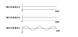
- the timing for generating the static magnetic field and the alternating magnetic field is not particularly limited. However, since the traveling direction is usually determined quickly by the static magnetic field, the static magnetic field is generated slightly before the generation of the alternating magnetic field, or at the same time. These may be generated and then generated at the same time and synthesized. For example, if the traveling direction is 45 degrees with respect to the x axis, 45 degrees with respect to the y axis, and 90 degrees with respect to the z axis, the magnetic field component in the x axis direction and the magnetic field in the y axis direction as shown in FIG. The component may be a static magnetic field component having an equal value, and the magnetic field in the z-axis direction may be an alternating magnetic field.
- the traveling speed is slowed down in accordance with a control signal from the operation unit 33, which will be described later, so that the image from the capsule endoscope 2 can be observed in detail, or the propulsive force is increased to pass through. It is also possible to facilitate passage through difficult places.
- the magnitude of the static magnetic field is made variable so that the magnitude of the force directed in the traveling direction can be controlled in accordance with a control signal from the operation unit 33 described later, so that it is difficult to face the target traveling direction due to an obstacle or the like. It is also possible to make it easier to face.
- the amplitude and frequency of the AC magnetic field variable it can be made to have a size corresponding to the angle of rotation of a terminal 33a ′ (see FIG. 1) to be described later or the angle of tilt of a joystick 33b to be described later. It is possible to prepare a lever (not shown) that is moved by hand or an accelerator (not shown) that is stepped on by a foot so as to have a size corresponding to the moving distance of the lever or the amount of depression of the accelerator.
- the magnitude of the static magnetic field variable it can be changed when the amplitude or frequency of the alternating magnetic field changes, or can be changed independently by a terminal 33a ', a lever, or the like.
- the direction in which the fin portion 2b vibrates and the direction of the AC magnetic field are nearly perpendicular, and the fin portion 2b is difficult to vibrate.
- a control signal from the operation unit 33 is used. Accordingly, the direction of the alternating magnetic field can be changed within a range orthogonal to the static magnetic field.
- the traveling direction and the propulsive force (traveling speed) of the capsule endoscope 2 can be controlled independently, it is easy to move the capsule endoscope 2 exactly where it is desired to be inspected.
- the capsule control device 3 has the operation unit 33 operated by the inspector as described above.
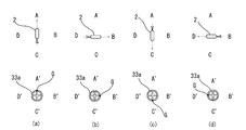
- the operation unit 33 controls the traveling direction of the capsule endoscope 2 using an operation device such as a handle 33a as shown in FIGS. 1 and 6 or a joystick 33b as shown in FIG.
- the direction of the static magnetic field is controlled based on the signal output from the operation unit 33.
- a device for controlling the amplitude, frequency, or direction of the alternating magnetic field, a device for controlling the magnitude of the static magnetic field, and the like can be provided.
- the in-vivo image transmitted from the capsule endoscope 2 is received by the communication unit 34 and displayed on the display device 35.
- the inspector can operate operation devices such as the handle 33a and the joystick 33b while viewing the image.
- the operation unit 33 using the handle 33a can be configured as follows.
- the handle 33a holds its rotational position.
- the static magnetic field is oriented in the A direction (see FIG. 6A).
- Direction D direction.
- the capsule endoscope 2 is oriented in the A direction.
- the image from the capsule endoscope 2 is an image in the A direction. The examiner observes the image from the capsule endoscope 2 and adjusts the traveling speed with the terminal 33a '(see FIG. 1) or the like without rotating the handle 33a when going straight ahead.
- the handle 33a When observing the image and changing the direction of the capsule endoscope 2, the handle 33a is turned right or left. For example, when the image is observed and the direction of the capsule endoscope 2 is to be changed to 90 degrees clockwise with respect to the traveling direction, the handle 33a is turned 90 degrees to the right. Then, the reference point G of the handle 33a is on the right side (B ′ direction), the static magnetic field is directed in the B direction (see FIG. 6B), and the capsule endoscope 2 is directed in the B direction. Similarly, when the capsule endoscope 2 is oriented in the B direction and the image is observed and the direction of the capsule endoscope 2 is changed to 90 degrees clockwise with respect to the traveling direction, the handle 33a is turned 90 degrees clockwise. .
- the reference point G of the handle 33a is on the lower side (C ′ direction), the static magnetic field is directed in the C direction (see FIG. 6C), and the capsule endoscope 2 is directed in the C direction.
- the handle 33a is turned 90 degrees clockwise.
- the reference point G of the handle 33a is on the left side (D ′ direction), the static magnetic field is directed in the D direction (see FIG. 6D), and the capsule endoscope 2 is directed in the D direction.
- the operation unit 33 using the handle 33a directs the static magnetic field in the direction corresponding to the reference point G, so that the left and right traveling directions of the screen to be observed by the operation (rotation operation) of the handle 33a.
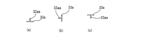
- Control of the vertical direction of the observed screen can be achieved by changing the moving distance of the movable part of the slider 33a '' as shown in FIG. 1, or by changing the inclination angle of the shaft 33aa of the handle 33a as shown in FIG.
- the static magnetic field may be controlled to an arbitrary angle within a range of ⁇ 90 degrees to 90 degrees with respect to the horizontal plane.
- the terminal 33a 'and the slider 33a' ' can use other types of devices.
- a lever can be used instead of the slider 33a ′′.
- the reference point G may not be visible.
- the operation unit 33 using the joystick 33b can be configured as follows.
- the joystick 33b has an angle from A ′ to the reference point H so that the reference point H of the joystick base 33b ′ automatically rotates or in some cases manually rotates by an angle corresponding to the direction in which the joystick 33 is tilted. Only rotate the direction of the static magnetic field.
- the static magnetic field is oriented in the A direction (see FIG. 8A)
- the B direction is sequentially 90 degrees from the A direction.
- C direction and D direction When the static magnetic field is oriented in the A direction, the capsule endoscope 2 is oriented in the A direction.
- the image from the capsule endoscope 2 is an image in the A direction.
- the examiner observes the image from the capsule endoscope 2 and, when going straight, tilts the joystick 33b upward (A ′ direction). Then, the capsule endoscope 2 goes straight at a traveling speed corresponding to the angle at which the joystick 33b is tilted.
- the joystick 33b When observing the image and changing the direction of the capsule endoscope 2, the joystick 33b is tilted in the direction to be changed. For example, when observing an image and changing the direction of the capsule endoscope 2 by 90 degrees clockwise with respect to the traveling direction, the joystick 33b is tilted to the right. Then, the joystick base 33b ′ rotates and the reference point H is on the right side (B ′ direction), the static magnetic field is directed in the B direction (see FIG. 8B), and the capsule endoscope 2 is in the B direction. Turn to.
- the joystick 33b is temporarily returned to stand up. Then, tilt the joystick 33b to the right again. Then, the joystick base 33b ′ rotates and the reference point H is on the lower side (C ′ direction), the static magnetic field faces in the C direction (see FIG. 8C), and the capsule endoscope 2 in the C direction. Is suitable.
- the joystick 33b is temporarily returned to stand up.
- the operation unit 33 using the joystick 33b can control the left and right traveling directions of the observed screen by operating the joystick 33b by directing the static magnetic field in the direction corresponding to the reference point H. is there.
- Control of the vertical direction of the observed screen is performed by using the slider 33a ′′ or the like described above, or by changing the tilt angle of the joystick base 33b ′ as shown in FIG.
- the angle may be controlled to an arbitrary angle within a range of ⁇ 90 degrees to 90 degrees.
- the states of the joystick base 33b ′ shown in FIGS. 9A, 9B, and 9C can be made to correspond to when the static magnetic field is inclined by ⁇ 90 degrees, 0 degrees, and 90 degrees with respect to the horizontal plane, respectively.
- the joystick 33b is shown standing.
- the slider 33a '' can use another type of device (for example, a lever).
- the reference point H may not be visible.
- the embodiment in which the capsule control device 3 is configured using the magnetic field generation unit 31 has been described above.
- the magnetic field generator 31 having three sets of Helmholtz coils is used, the magnetic field becomes substantially uniform as described above, so that it is easy to control the traveling direction and the propulsive force (traveling speed).
- Each set of Helmholtz coils is a set of coil pairs composed of two coils arranged coaxially and in parallel.
- the shape of any one or two coil pairs of the magnetic field generating unit 31 having three Helmholtz coils, or three coil pairs is changed, or the size of the coil is changed. It is possible to change the length or to change the distance between two coils constituting the coil pair.
- the magnetic field is non-uniform (not uniform) and varies depending on the location, as described below.
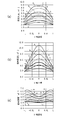
- the characteristics shown in FIG. 10 are obtained by simulating the magnetic flux density in the y-axis direction of a magnetic field when a pair of coil pairs are arranged so as to generate a magnetic field in the y-axis direction.
- the horizontal axis is the y-axis coordinate value centered on the middle between the two coils, and the unit length is L.
- (A), (b), and (c) of FIG. 10 respectively show the arrangement of one coil pair with the distance between two coils being L, 0.5L, and 2L.
- a curve “a” in each figure indicates characteristics of a circumferential coil having a radius L (see FIG. 11A).
- the curve b in the figure is a square with a side of 2L
- the curve c is a rectangle with a short side of 2L and a long side of 3L
- the curve d is a rectangle with a short side of 2L and a long side of 4L
- the curve e has a short side of 2L.
- FIG. 11 shows characteristics of a rectangular coil having a long side of 5 L and an outer peripheral shape (see FIG. 11B).
- Curves f, g, h, i in the figure show the characteristics of an octagonal outer peripheral coil produced by deleting all the square corners by a length of 0.5 L (FIG. 11).
- the curve f is a square having a side of 2L
- the curve g is a rectangle having a short side of 2L and a long side of 3L
- the curve h is a rectangle having a short side of 2L and a long side of 4L.
- octagons each made from a rectangle with a short side of 2L and a long side of 5L.
- the curve a in FIG. 10A is the characteristic of a set of Helmholtz coils.
- the coil shape is a polygon such as a quadrangle or an octagon, and the distance between the two coils is the distance of the Helmholtz coil (between the two coils constituting the Helmholtz coil). If it is different from (distance), the magnetic field changes depending on the location, and away from the characteristics of the Helmholtz coil.
- the distance between the two coils is the Helmholtz coil distance
- the size of one direction of the coil (long side direction) is the size of the other direction (short side direction) perpendicular to it.
- the magnetic field generator 36 includes a set of Helmholtz coils and a Helmholtz coil structure (the shape and size of the coil and the distance between the two coils) so as to surround the capsule endoscope 2 from three directions orthogonal to each other. And two sets of coil pairs with different values.
- the set of Helmholtz coils is a set of z-axis Helmholtz coils 36z and 36z 'that generate a magnetic field in the z-axis direction.
- the other two coil pairs include a pair of x-axis coil pairs 36x and 36x ′ that generate a magnetic field in the x-axis direction and a pair of y-axis coil pairs 36y and 36y that generate a magnetic field in the y-axis direction. 'And consist of.
- the magnetic field generator 36 Compared with the magnetic field generator 31 having three sets of Helmholtz coils, the magnetic field generator 36 has a larger change in the magnetic field depending on the location in the x-axis direction and the y-axis direction, while preventing a plurality of orthogonal Helmholtz coils from overlapping each other. Therefore, the overall size can be reduced.
- the magnetic field generator 36 has a uniform magnetic field in the z-axis direction, the magnetic fields in the x-axis direction and the y-axis direction tend to be slightly difficult because the magnetic fields in the x-axis direction and the y-axis direction are not uniform. It is possible to generate a static magnetic field and an alternating magnetic field in the same manner as 31 and control the traveling direction and traveling speed of the capsule endoscope 2.
- the coils 36x, 36x ', 36y, 36y' constituting the coil pair can have a polygonal outer peripheral shape or an elliptical or circular outer peripheral shape that is closer to the shape of a Helmholtz coil.
- the coils 36x, 36x ′, 36y, and 36y ′ are long and large in size in the y-axis direction or the x-axis direction larger than the size in the z-axis direction.
- the outer peripheral shape is a square or an ellipse, it is possible to suppress changes depending on the location of the magnetic field in the x-axis direction and the y-axis direction while reducing the size in the z-axis direction.
- any one or two coil pairs of the magnetic field generator 31 having three sets of Helmholtz coils, or the shape of the coils of the three coil pairs can be changed. It is possible to change the size of the coil and the distance between the two coils.
- the coils constituting the three pairs of coils are selected from polygonal, elliptical, or circular peripheral shapes. When the coil has a polygonal outer peripheral shape, a rectangular or polygonal outer peripheral shape having more corners than the quadrangle, which is preferable in terms of the above-described characteristics, can be used.
- any one or two of the three coil pairs, or the coil constituting the three coil pairs is a long polygon or ellipse that is preferable in terms of the above-described characteristics. Can be used.
- the magnetic field generator 37 it is also possible to use one set of Helmholtz coils and two sets of electromagnets that surround the capsule endoscope 2 from three directions orthogonal to each other.
- the magnetic field generator 37 includes a set of x-axis electromagnets 37x and 37x ′ that generates a magnetic field in the x-axis direction, a set of y-axis Helmholtz coils 37y that generates a magnetic field in the y-axis direction, 37y ′ and a pair of z-axis electromagnets 37z and 37z ′ that generate a magnetic field in the z-axis direction.
- the inspected person may lie or stand parallel to the y-axis direction.
- Such a magnetic field generator 37 composed of one set of Helmholtz coils and two sets of electromagnets becomes heavier and the magnetic field becomes very uneven (not uniform), but the size of the electromagnet is small, Since the size of the radius and interval of one set of Helmholtz coils can be freely reduced, the overall size can be reduced.
- the magnetic field generation unit 37 tends to be difficult to control because the magnetic fields in the x-axis direction and the z-axis direction are not uniform. However, the magnetic field generation unit 37 generates a static magnetic field and an alternating magnetic field, and the traveling direction and progress of the capsule endoscope 2. The speed can be controlled.
- the present invention has been described above.
- the present invention is not limited to that described in the embodiment, and various design changes can be made within the scope of the matters described in the claims. It is.
- various structures and shapes of the endoscope main body 2a of the capsule endoscope 2 are possible.
- the operation unit 33 of the capsule control device 3 is not limited to a specific shape with respect to the handle 33a and the joystick 33b.
- the handle 33a has a dial shape and a knob shape in addition to the shape shown in FIG. Shapes, joystick shapes that do not stand up, etc. are possible.
- the operation unit 33 of the capsule control device 3 uses a keyboard, mouse, touch panel, etc.
Abstract
Provided is a medical device comprising a self-propelled capsule endoscope which propels itself inside the human body by oscillation of a fin portion and a capsule control device which controls self-propulsion of the capsule endoscope from outside the body, the medical device being capable of precisely controlling the direction of movement of the capsule endoscope easily. This medical device (1) comprises: a capsule endoscope (2) which is equipped with a magnet (21) having a magnetization direction in an axial direction, is provided with a fin portion (2b) on the rear end of the endoscope main body (2a) in the axial direction and which can be self-propelled inside the body; and a capsule control device (3) which controls self-propulsion of the capsule endoscope (2) from outside the body by generating a static magnetic field and an alternating magnetic field orthogonal thereto the directions of which are controlled three dimensionally. The capsule endoscope (2) receives the static magnetic field and moves rotationally such that the magnetization direction is parallel to the direction of the static magnetic field, and receives the alternating magnetic field to which the magnet (21) reacts whereby the fin portion (2b) bends and oscillates which then generates a propelling force in the axial direction.
Description
本発明は、体内において自走可能なカプセル内視鏡と、体外においてカプセル内視鏡の自走を制御するカプセル制御装置と、を備えた医療装置に関する。
The present invention relates to a medical device including a capsule endoscope capable of self-running inside the body and a capsule control device that controls self-running of the capsule endoscope outside the body.
近年においては、体内において自走可能なカプセル内視鏡を用いて体内を検査する医療装置が知られている。この医療装置におけるカプセル内視鏡は、一般に、旧来の内視鏡のように内視鏡を操作するための食道等を通過する管を必要としないために、被検査者への負担が少なくなる。カプセル内視鏡は、これを被検査者が飲み込むと、胃や腸の蠕動運動により体内を進行しながら内蔵されているカメラで周囲を撮影し、撮影された画像が体外においてカプセル内視鏡の自走を制御するカプセル制御装置に送信され記憶媒体に記憶される。その後、カプセル内視鏡は、肛門から外部に排出される。
In recent years, a medical device that inspects the inside of a body using a capsule endoscope capable of self-propelling in the body is known. In general, the capsule endoscope in this medical apparatus does not require a tube passing through the esophagus or the like for operating the endoscope unlike the conventional endoscope, and therefore the burden on the examinee is reduced. . When the subject swallows the capsule endoscope, the surroundings are photographed with a built-in camera while moving inside the body by the peristaltic movement of the stomach and intestines, and the captured image is taken outside the body of the capsule endoscope. It is transmitted to the capsule control device that controls self-running and stored in the storage medium. Thereafter, the capsule endoscope is discharged from the anus to the outside.
このような自走可能なカプセル内視鏡は、蠕動運動によって受動的に移動する他に、自ら検査したいところに移動することができる。例えば、特許文献1には、軸方向(長手方向)と直交方向に磁化方向を有する磁石が搭載され、また、軸方向後端部に螺旋構造の推力発生部が設けられたカプセル内視鏡が記載されている。このカプセル内視鏡は、体外のカプセル制御装置で発生させた回転する磁場を受けて磁石が回転し、それにより推力発生部が回転することにより軸方向の推進力が生じる。
Such a self-propelled capsule endoscope can be moved to a place to be examined by itself, in addition to being passively moved by a peristaltic motion. For example, Patent Document 1 discloses a capsule endoscope in which a magnet having a magnetization direction orthogonal to an axial direction (longitudinal direction) is mounted, and a thrust generating portion having a helical structure is provided at a rear end portion in the axial direction. Are listed. The capsule endoscope receives a rotating magnetic field generated by the capsule control apparatus outside the body, and the magnet rotates, whereby the thrust generating unit rotates, thereby generating an axial propulsive force.
特許文献2には、軸方向(長手方向)に磁化方向を有する磁石が搭載され、また、軸方向後端部にヒレ部が設けられたカプセル内視鏡が記載されている。このカプセル内視鏡は、体外のカプセル制御装置で発生させた交流磁場を受けて磁石が振動し、それによりヒレ部が曲がって振動して周囲の液体を後方に押し出すことにより軸方向の推進力が生じる。なお、特許文献2では、一方向の交流磁場を発生する電磁石の位置をガイドレールとリフトによって制御することにより、カプセル内視鏡を検査したいところに移動させている。
Patent Document 2 describes a capsule endoscope in which a magnet having a magnetization direction in an axial direction (longitudinal direction) is mounted, and a fin portion is provided at a rear end portion in the axial direction. This capsule endoscope receives an alternating magnetic field generated by the capsule control device outside the body, and the magnet vibrates, whereby the fin portion bends and vibrates to push the surrounding liquid backward, thereby pushing the axial propulsive force. Occurs. In Patent Document 2, the position of an electromagnet that generates a unidirectional alternating magnetic field is controlled by a guide rail and a lift, so that the capsule endoscope is moved to a place where inspection is desired.
特許文献2のカプセル内視鏡は、交流磁場の方向にヒレ部が曲がるように姿勢が安定するので、特許文献1のカプセル内視鏡のように推力発生部の回転にともなって内蔵されているカメラによって撮影された画像の回転又は不安定な傾きが発生し易いものに比べ、画像が安定して検査し易いものとなる。また、特許文献2のカプセル内視鏡は、ヒレ部によって多量の液体を強い力で後方に移動させることができるので、特許文献1のように推力発生部の回転によって推進力を得るものに比べ、小型であっても推進力を大きくすることが容易であり、また、摩擦により体壁(体内の壁面)を傷付ける可能性を低減することが可能である。
Since the posture of the capsule endoscope of Patent Document 2 is stabilized so that the fin portion bends in the direction of the alternating magnetic field, the capsule endoscope is incorporated along with the rotation of the thrust generating portion like the capsule endoscope of Patent Document 1. The image is stable and easy to inspect as compared to the image that is easily rotated or unstable tilted by the camera. Moreover, since the capsule endoscope of Patent Document 2 can move a large amount of liquid backward with a strong force by the fin portion, as compared with the one that obtains a propulsive force by rotation of the thrust generating portion as in Patent Document 1. Even if it is small, it is easy to increase the propulsive force, and it is possible to reduce the possibility of damaging the body wall (wall surface in the body) due to friction.
このように特許文献2に記載されているようなヒレ部の振動により推進するカプセル内視鏡は、幾つかの利点を有している。ところで、体内のカプセル内視鏡が進んでいく経路は、胃のように比較的広い場所や腸のように屈曲しているところが様々に存在しているため、カプセル内視鏡の進行方向の制御は重要である。ヒレ部の振動により推進するカプセル内視鏡は、交流磁場に平行なバイアス磁場を加えることで進行方向を変えて行くことが可能である。
As described above, the capsule endoscope propelled by the vibration of the fin portion as described in Patent Document 2 has several advantages. By the way, there are various paths that the capsule endoscope travels in the body, such as a relatively wide place like the stomach and a bent place like the intestine, so control of the traveling direction of the capsule endoscope is possible. Is important. The capsule endoscope driven by the vibration of the fin portion can change the traveling direction by applying a bias magnetic field parallel to the alternating magnetic field.
しかし、交流磁場に平行なバイアス磁場を加える方法では、カプセル内視鏡は移動しながらその進行方向を徐々に変えて行くので、検査したいところに正確に移動させることは必ずしも容易ではない。
However, with the method of applying a bias magnetic field parallel to the alternating magnetic field, the capsule endoscope gradually changes its traveling direction while moving, so it is not always easy to move it precisely where it is desired to be inspected.
本発明は係る事由に鑑みてなされたものであり、その目的は、体内においてヒレ部の振動により推進する自走可能なカプセル内視鏡と、体外においてカプセル内視鏡の自走を制御するカプセル制御装置と、を備えた医療装置において、カプセル内視鏡の進行方向の精密な制御が容易にできる医療装置を提供することにある。
SUMMARY OF THE INVENTION The present invention has been made in view of the above-mentioned reasons, and has as its object the self-propelled capsule endoscope that is propelled by the vibration of the fin portion in the body, and the capsule that controls the self-running of the capsule endoscope outside the body. It is an object of the present invention to provide a medical device that can easily perform precise control of the traveling direction of a capsule endoscope.
上記目的を達成するために、本発明の好ましい実施形態に係る医療装置は、軸方向に磁化方向を有する磁石が搭載され、内視鏡本体部の軸方向後端部にヒレ部が設けられて体内において自走可能なカプセル内視鏡と、3次元で方向が制御される静磁場とそれと直交する交流磁場を発生することにより体外においてカプセル内視鏡の自走を制御するカプセル制御装置と、を備えており、前記カプセル内視鏡は、前記静磁場を受けてその静磁場の方向に磁化方向が平行になるように回動し、前記交流磁場を受けて前記磁石が応動しそれにより前記ヒレ部が曲がって振動して軸方向の推進力が生じる。
In order to achieve the above object, a medical device according to a preferred embodiment of the present invention is equipped with a magnet having a magnetization direction in the axial direction, and a fin portion is provided at the axial rear end of the endoscope body. A capsule endoscope capable of self-running in the body, a capsule control device for controlling the self-running of the capsule endoscope outside the body by generating a static magnetic field whose direction is controlled in three dimensions and an alternating magnetic field orthogonal thereto; The capsule endoscope receives the static magnetic field, rotates so that the magnetization direction is parallel to the direction of the static magnetic field, receives the alternating magnetic field, and the magnet responds accordingly. The fins bend and vibrate to produce axial thrust.
好ましくは、前記カプセル制御装置は、3組のヘルムホルツコイルを有する磁場発生部により静磁場と交流磁場を発生させるようにする。又は、前記カプセル制御装置は、3組のコイル対を有する磁場発生部により静磁場と交流磁場を発生させており、前記3組のそれぞれのコイル対は、それを構成するコイルが、多角形、楕円又は円の外周形状のうちから選ばれるようにする。この場合、前記3組のコイル対のうちのいずれか1組又は2組のコイル対、或いは3組のコイル対は、それを構成するコイルが長形の多角形又は楕円の外周形状であるのが好ましい。又は、前記カプセル制御装置は、1組のヘルムホルツコイルと2組の電磁石を有する磁場発生部により静磁場と交流磁場を発生させるようにする。
Preferably, the capsule controller generates a static magnetic field and an alternating magnetic field by a magnetic field generator having three sets of Helmholtz coils. Alternatively, the capsule control device generates a static magnetic field and an alternating magnetic field by a magnetic field generation unit having three sets of coil pairs, and each of the three sets of coil pairs has a polygonal shape, The shape is selected from an elliptical shape or a circular shape. In this case, any one or two of the three coil pairs, or the three coil pairs, is a long polygonal or elliptical outer peripheral coil. Is preferred. Alternatively, the capsule control device generates a static magnetic field and an alternating magnetic field by a magnetic field generator having one set of Helmholtz coils and two sets of electromagnets.
更に好ましくは、前記カプセル制御装置は、前記交流磁場の振幅及び/又は周波数が可変、及び/又は静磁場の大きさが可変であるようにする。この場合、前記交流磁場の振幅及び/又は周波数及び/又は静磁場の大きさは、端子の回す角度、ジョイスティックの倒す角度、レバーの移動距離、又はアクセルの踏込量に応じた大きさになるのが好ましい。
More preferably, the capsule controller is configured such that the amplitude and / or frequency of the alternating magnetic field is variable and / or the magnitude of the static magnetic field is variable. In this case, the amplitude and / or frequency of the alternating magnetic field and / or the magnitude of the static magnetic field are in accordance with the angle at which the terminal is turned, the angle at which the joystick is tilted, the lever moving distance, or the accelerator depression amount. Is preferred.
更に好ましくは、前記静磁場の方向は、回転位置が保持されるハンドルを用いた操作部によって制御され、該ハンドルの基準点の方向に応じた方向になるようにする。この場合、前記静磁場の水平面に対する傾斜角度は、前記ハンドルの軸の傾斜角度を変える、又は、スライダーの可動部又はレバーの移動距離を変えることによって制御されるようにする。又は、前記静磁場の方向は、ジョイスティックを用いた操作部によって制御され、該ジョイスティックを倒した方向に対応する角度だけジョイスティック台の基準点が回転し、前記静磁場は該基準点の方向に応じた方向になるようにする。この場合、前記静磁場の水平面に対する傾斜角度は、前記ジョイスティック台の傾斜角度を変える、又は、スライダーの可動部又はレバーの移動距離を変えることによって制御されるようにする。
More preferably, the direction of the static magnetic field is controlled by an operation unit using a handle in which the rotational position is held, so that the direction corresponds to the direction of the reference point of the handle. In this case, the inclination angle of the static magnetic field with respect to the horizontal plane is controlled by changing the inclination angle of the shaft of the handle or changing the moving distance of the movable part of the slider or the lever. Alternatively, the direction of the static magnetic field is controlled by an operation unit using a joystick, the reference point of the joystick base rotates by an angle corresponding to the direction in which the joystick is tilted, and the static magnetic field depends on the direction of the reference point. To be in the right direction. In this case, the inclination angle of the static magnetic field with respect to the horizontal plane is controlled by changing the inclination angle of the joystick table or changing the moving distance of the movable part of the slider or the lever.
本発明の医療装置によれば、体内のカプセル内視鏡の進行方向を静磁場により制御し、それと独立に、推進力を静磁場に直交する交流磁場により制御するので、カプセル内視鏡の進行方向及び進行速度の精密な制御が容易になる。
According to the medical device of the present invention, the advancing direction of the capsule endoscope in the body is controlled by a static magnetic field, and independently, the propulsive force is controlled by an alternating magnetic field orthogonal to the static magnetic field. Precise control of direction and speed is facilitated.
以下、本発明を実施するための好ましい形態について図面を参照しながら説明する。本発明の実施形態に係る医療装置1は、被検査者の体内の検査等を行うもので、図1に示すように、被検査者の体内において自走可能なカプセル内視鏡2と、体外においてカプセル内視鏡2の自走を制御するカプセル制御装置3と、を備えている。被検査者は、通常、後述するカプセル制御装置3の磁場発生部31が画定する所要範囲の内方に胴部を位置させ、カプセル内視鏡2を口から飲み込んだ上で検査を受ける。肛門からカプセル内視鏡2を逆走させることも可能である。
Hereinafter, preferred embodiments for carrying out the present invention will be described with reference to the drawings. A medical device 1 according to an embodiment of the present invention performs an inspection or the like inside a subject's body. As shown in FIG. 1, a capsule endoscope 2 capable of self-running in the subject's body, and an external body And a capsule control device 3 for controlling the self-running of the capsule endoscope 2. The person to be inspected is usually inspected after the body part is positioned inside a required range defined by a magnetic field generation unit 31 of the capsule control device 3 to be described later and the capsule endoscope 2 is swallowed from the mouth. It is also possible to reverse the capsule endoscope 2 from the anus.
カプセル内視鏡2は、軸方向(長手方向)に進行する全体的に大略円柱状のものであって、図2に示すように、内部にカメラ22などを搭載する内視鏡本体部2aと、内部に軸方向に磁化方向を有する磁石21を搭載するヒレ部2bと、を有している。ヒレ部2bは、内視鏡本体部2aの軸方向後端部に設けられており、詳しくはヒレ部2bの前端が内視鏡本体部2aの後端に固定されるか或いはキャップ形状の媒体などを介して固定されている。カプセル内視鏡2は、本実施形態では、例えば、軸方向の長さが例えば4.5cm前後程度、直径が1cm前後程度の大きさである。
The capsule endoscope 2 has a generally cylindrical shape that travels in the axial direction (longitudinal direction). As shown in FIG. 2, the capsule endoscope 2 includes an endoscope main body 2a in which a camera 22 and the like are mounted. And a fin portion 2b on which a magnet 21 having a magnetization direction in the axial direction is mounted. The fin portion 2b is provided at the rear end portion in the axial direction of the endoscope main body portion 2a. Specifically, the front end of the fin portion 2b is fixed to the rear end of the endoscope main body portion 2a or a cap-shaped medium. Etc. are fixed through. In the present embodiment, the capsule endoscope 2 has, for example, an axial length of about 4.5 cm and a diameter of about 1 cm.
内視鏡本体部2aの構造は本発明の要旨ではなく、従来のカプセル内視鏡で用いられている公知のものが流用可能である。このような内視鏡本体部2aは、一般的には、図2に示すように、前述のカメラ22の他に、カプセル内視鏡2の各部に電源を供給する電源供給部23、カメラ22による撮影のために外部を照射する照射部24、カメラ22が撮影した画像を処理して無線でカプセル制御装置3に送信する無線通信部25、などが含まれる。内視鏡本体部2aの前部(図2においては左方)は光が通過できる程度に透明である。カメラ22はCCDなどから、電源供給部23は電池などから、照射部24はLEDなどから、それぞれ構成される。無線通信部25は、カプセル制御装置3から無線で制御信号を受信し、カメラ22や照射部24などを制御できるようにしてもよい。
The structure of the endoscope body 2a is not the gist of the present invention, and a known structure used in a conventional capsule endoscope can be used. As shown in FIG. 2, such an endoscope main body 2 a generally includes a power supply unit 23 that supplies power to each part of the capsule endoscope 2 and a camera 22 in addition to the camera 22 described above. An irradiation unit 24 that irradiates the outside for shooting by the camera, a wireless communication unit 25 that processes an image shot by the camera 22 and transmits it to the capsule controller 3 wirelessly, and the like. The front part (left side in FIG. 2) of the endoscope body 2a is transparent to the extent that light can pass through. The camera 22 includes a CCD, the power supply unit 23 includes a battery, and the irradiation unit 24 includes an LED. The wireless communication unit 25 may receive a control signal wirelessly from the capsule control device 3 and control the camera 22, the irradiation unit 24, and the like.
ヒレ部2bの磁石21は、棒状の磁石であり、前述したように、カプセル内視鏡2の軸方向と同じ磁化方向を有している。磁石21は、シリコン樹脂などのように弾力性のある部材の内部に搭載されている。磁石21は、後述するようにカプセル制御装置3の磁場発生部31で発生する静磁場とそれと直交する交流磁場を受ける。磁石21は、静磁場を受けると、その静磁場の方向に平行になるように回動する。そして、その回動に従ってカプセル内視鏡2が回動する。また、磁石21は、交流磁場を受けるとそれに応動して振動する。そして、それにより、図3に示すように、ヒレ部2bが曲がって振動し、周囲の液体を後方に押し出すことにより軸方向の推進力が生じる。
The magnet 21 of the fin portion 2b is a rod-shaped magnet and has the same magnetization direction as the axial direction of the capsule endoscope 2 as described above. The magnet 21 is mounted inside an elastic member such as silicon resin. As will be described later, the magnet 21 receives a static magnetic field generated by the magnetic field generator 31 of the capsule control device 3 and an alternating magnetic field orthogonal thereto. When receiving the static magnetic field, the magnet 21 rotates so as to be parallel to the direction of the static magnetic field. And the capsule endoscope 2 rotates according to the rotation. Further, when the magnet 21 receives an alternating magnetic field, the magnet 21 vibrates in response thereto. Then, as shown in FIG. 3, the fin portion 2b bends and vibrates, and pushes the surrounding liquid backward to generate an axial propulsive force.
磁石21は、ヒレ部2bの前端が内視鏡本体部2aに固定され後端が開放されているので、振動するときは交流磁場に応じて後端(図2ではS極側)が大きく移動し、前端(図2ではN極側)はきわめて小さく振動する(図3参照)。
Since the front end of the fin portion 2b is fixed to the endoscope body portion 2a and the rear end is opened, the magnet 21 moves greatly at the rear end (S pole side in FIG. 2) according to the alternating magnetic field when vibrating. The front end (N pole side in FIG. 2) vibrates very small (see FIG. 3).
ヒレ部2bは、魚のヒレのように曲がって効率良く液体を後方に押し出せるような幅広の側面を有している。その側面の形状は、適宜適切なものにすればよいが、例えば、図2(a)に示すような後部半分くらい台形形状になるようにしたり、全体的に丸みを帯びた形状にしたり、長方形状にしたりすることができる。また、ヒレ部2bの厚み(幅広の側面に直交する面の幅)は、図2(b)に示すように前部半分くらいを薄く、後部半分くらいを更に薄くしてもよい。また、ヒレ部2b全体の厚みを同じくらいの薄さにしてもよい。カプセル内視鏡2は、交流磁場により、ヒレ部2bの幅広の側面に交流磁場が垂直に入射してヒレ部2bが曲がるような姿勢が安定姿勢となる。
The fin portion 2b has a wide side surface that bends like a fish fin and can efficiently extrude the liquid backward. The shape of the side surface may be appropriately set as appropriate. For example, it may have a trapezoidal shape such as a rear half as shown in FIG. 2 (a), a rounded shape as a whole, or a rectangular shape. Or can be made into a shape. Further, as shown in FIG. 2 (b), the thickness of the fin portion 2b (the width of the surface orthogonal to the wide side surface) may be made thinner about the front half and further thinner about the rear half. Moreover, you may make the thickness of the whole fin part 2b as thin as the same. The capsule endoscope 2 has a stable posture in which the alternating magnetic field is perpendicularly incident on the wide side surface of the fin portion 2b and the fin portion 2b is bent by the alternating magnetic field.
次に、カプセル制御装置3を説明する。カプセル制御装置3は、図1及び図4に示すように、カプセル内視鏡2を互いに直交する3方向から取り囲む磁場発生部31、すなわち、3組のヘルムホルツコイルであるx軸方向(図1では左右方向)の磁場を生成する一組のx軸ヘルムホルツコイル31x、31x’、y軸方向(図1では上下方向)の磁場を生成する一組のy軸ヘルムホルツコイル31y、31y’、z軸方向の磁場(図1では紙面に垂直方向)を生成する一組のz軸ヘルムホルツコイル31z、31z’を有している。なお、図1においては、被検査者はy軸方向と平行に横たわったり又は立ったりしている。また、図1においては、他方のz軸ヘルムホルツコイル31z’は、一方のz軸ヘルムホルツコイル31zの背後に位置している。
Next, the capsule control device 3 will be described. As shown in FIGS. 1 and 4, the capsule controller 3 includes a magnetic field generator 31 that surrounds the capsule endoscope 2 from three directions orthogonal to each other, that is, the x-axis direction that is three sets of Helmholtz coils (in FIG. 1). A set of x-axis Helmholtz coils 31x, 31x ′ that generate a magnetic field in the left-right direction) A set of y- axis Helmholtz coils 31y, 31y ′ that generate a magnetic field in the y-axis direction (vertical direction in FIG. 1), z-axis direction A pair of z-axis Helmholtz coils 31z and 31z ′ for generating a magnetic field (in FIG. 1, a direction perpendicular to the paper surface). In FIG. 1, the subject is lying or standing parallel to the y-axis direction. In FIG. 1, the other z-axis Helmholtz coil 31z 'is located behind one z-axis Helmholtz coil 31z.
磁場発生部31は、磁場制御部32からの制御電流により、時間的に変化しない静磁場を発生したり、所定の周波数及び振幅で時間的に変化する交流磁場を発生したりすることができ、また、静磁場と交流磁場を合成して発生することができる。静磁場と交流磁場は、3次元のどの方向にでも向かせることが可能である。具体的には、後述する操作部33からの制御信号に基づいて、磁場制御部32のx軸磁場制御部32xがx軸方向の磁場成分を生成するような電流をx軸ヘルムホルツコイル31x、31x’に流し、y軸磁場制御部32yがy軸方向の磁場成分を生成するような電流をy軸ヘルムホルツコイル31y、31y’に流し、z軸磁場制御部32zがz軸方向の磁場成分を生成するような電流をz軸ヘルムホルツコイル31z、31z’に流す。
The magnetic field generation unit 31 can generate a static magnetic field that does not change with time by a control current from the magnetic field control unit 32, or can generate an alternating magnetic field that changes with time at a predetermined frequency and amplitude, Further, it can be generated by synthesizing a static magnetic field and an alternating magnetic field. The static magnetic field and the alternating magnetic field can be directed in any three-dimensional direction. Specifically, based on a control signal from the operation unit 33 to be described later, currents that cause the x-axis magnetic field control unit 32x of the magnetic field control unit 32 to generate a magnetic field component in the x-axis direction are supplied to the x-axis Helmholtz coils 31x and 31x. Is passed through the y- axis Helmholtz coils 31y, 31y 'so that the y-axis magnetic field control unit 32y generates a magnetic field component in the y-axis direction, and the z-axis magnetic field control unit 32z generates a magnetic field component in the z-axis direction. Such a current is passed through the z-axis Helmholtz coils 31z and 31z ′.
x軸ヘルムホルツコイル31x、31x’は、中心軸において一様な磁場を発生するように、導線を多重に巻いた円周形状のコイルがその半径の大きさRと同じ距離R’だけ離して同軸かつ平行に設置される構造であり、x軸ヘルムホルツコイル31x、31x’に同方向の電流を流すことで、中心軸において一様なx軸の方向の磁場を発生することができるものである。磁場を発生するのには、電磁石で用いられるような鉄芯は用いられない。実際上は、導線を多重に円周形状に巻いたコイルには幅や太さがあり、また、設置条件などもあるので多少のバラツキが生じるのが普通であるが、中心軸近傍の空間においてほぼ一様なx軸の方向の磁場を発生することができる。例えば、コイルの平均半径の大きさRに対する平均距離R’の許容バラツキを10%以内或いは20%以内とすることも可能である。中心軸近傍の空間においてほぼ一様な磁場を発生する点は、中心軸方向の位置に応じて磁場が大きく変わる電磁石と異なる点である。y軸ヘルムホルツコイル31y、31y’及びz軸ヘルムホルツコイル31z、31z’についても同様である。よって、磁場発生部31の中央近傍のある範囲においては、合成された磁場はどの方向でもほぼ一様な磁場となり、基本的にはこの範囲又はその近くでカプセル内視鏡2がカプセル制御装置3によって制御される。なお、x軸ヘルムホルツコイル31x、31x’の半径、y軸ヘルムホルツコイル31y、31y’の半径、z軸ヘルムホルツコイル31z、31z’は、通常は、半径及び間隔(距離)を大きくしながら順に外側に配置して行く必要がある。また、それらの半径及び間隔の大きさは、限定されるものではなく、また、半径及び間隔の大きさの順番が限定されるものではない。
The x-axis Helmholtz coils 31x and 31x ′ are coaxially separated from each other by a distance R ′ that is the same as the radius R of a circumferential coil in which a plurality of conductive wires are wound so that a uniform magnetic field is generated in the central axis. In addition, it has a structure installed in parallel, and a current in the same direction flows through the x-axis Helmholtz coils 31x and 31x ′, thereby generating a uniform magnetic field in the x-axis direction at the central axis. To generate a magnetic field, iron cores such as those used in electromagnets are not used. In practice, a coil in which conductive wires are wound in multiple circumferential shapes has a width and thickness, and there are usually some variations due to installation conditions, but in a space near the central axis, A substantially uniform magnetic field in the x-axis direction can be generated. For example, the allowable variation of the average distance R ′ with respect to the size R of the average radius of the coil can be within 10% or within 20%. The point that a substantially uniform magnetic field is generated in the space near the central axis is different from an electromagnet in which the magnetic field changes greatly according to the position in the central axis direction. The same applies to the y-axis Helmholtz coils 31y and 31y 'and the z-axis Helmholtz coils 31z and 31z'. Therefore, in a certain range near the center of the magnetic field generator 31, the synthesized magnetic field is a substantially uniform magnetic field in any direction. Basically, the capsule endoscope 2 is in this range or in the vicinity thereof. Controlled by. The radii of the x-axis Helmholtz coils 31x and 31x ′, the radii of the y-axis Helmholtz coils 31y and 31y ′, and the z-axis Helmholtz coils 31z and 31z ′ are usually outward in order with increasing radius and interval (distance). It is necessary to go. Further, the sizes of the radius and the interval are not limited, and the order of the radius and the interval is not limited.
静磁場は、カプセル内視鏡2の進行方向を制御するのに用いられる。磁場制御部32は、磁場発生部31の3組のヘルムホルツコイルのそれぞれに直流電流を流して静磁場を発生させ、合成された静磁場の方向が目標の進行方向になるようにする。そうすると、カプセル内視鏡2の磁石21は静磁場の方向に平行になるようにすばやく回動し、その回動に従ってカプセル内視鏡2が回動して目標の進行方向に一致するようになる。
The static magnetic field is used to control the traveling direction of the capsule endoscope 2. The magnetic field control unit 32 generates a static magnetic field by causing a direct current to flow through each of the three sets of Helmholtz coils of the magnetic field generation unit 31 so that the direction of the synthesized static magnetic field becomes the target traveling direction. Then, the magnet 21 of the capsule endoscope 2 is quickly rotated so as to be parallel to the direction of the static magnetic field, and the capsule endoscope 2 is rotated in accordance with the rotation to coincide with the target traveling direction. .
また、交流磁場は、カプセル内視鏡2を推進させるのに用いられる。磁場制御部32は、磁場発生部31の3組のヘルムホルツコイルのそれぞれに交流電流を流して交流磁場の成分を発生させ、その成分が合成された交流磁場の方向が前記静磁場と直交するようにする。そうすると、カプセル内視鏡2の磁石21は目標の進行方向に対し略直交する方向に振動し、その振動に従ってヒレ部2bが目標の進行方向に対し略直交する方向に振動し、その結果、カプセル内視鏡2は目標の進行方向に推進されて自走することとなる。
Moreover, the alternating magnetic field is used to propel the capsule endoscope 2. The magnetic field control unit 32 generates an alternating magnetic field component by causing an alternating current to flow through each of the three sets of Helmholtz coils of the magnetic field generating unit 31 so that the direction of the alternating magnetic field in which the components are combined is orthogonal to the static magnetic field. To. Then, the magnet 21 of the capsule endoscope 2 vibrates in a direction substantially orthogonal to the target traveling direction, and the fin portion 2b vibrates in a direction substantially orthogonal to the target traveling direction in accordance with the vibration. The endoscope 2 is propelled in the target traveling direction and is self-propelled.
ここで、磁場発生部31の中央近傍ではカプセル内視鏡2に作用する静磁場はほぼ一様であるので、カプセル内視鏡2は、その軸が静磁場の方向に平行になるように回動するのみで、特定の方向に引き寄せられることはほとんどない。従って、進行方向の制御がし易いものとなる。また、磁場発生部31の中央近傍ではカプセル内視鏡2に作用する交流磁場の大きさの位置依存性は非常に少ないので、進行速度の制御がし易いものとなる。
Here, since the static magnetic field acting on the capsule endoscope 2 is substantially uniform in the vicinity of the center of the magnetic field generating unit 31, the capsule endoscope 2 is rotated so that its axis is parallel to the direction of the static magnetic field. It only moves and is hardly pulled in a specific direction. Therefore, it becomes easy to control the traveling direction. Further, since the position dependence of the magnitude of the alternating magnetic field acting on the capsule endoscope 2 is very small near the center of the magnetic field generator 31, the traveling speed can be easily controlled.
静磁場と交流磁場を発生させるタイミングは特に限定されることはないが、通常は、静磁場によりすばやく進行方向は決まるので、静磁場を交流磁場の発生よりも少し前に発生させるか、或いは同時に発生させ、発生後はこれらを同時に発生させて合成するようにすればよい。例えば、x軸に対して45度、y軸に対して45度、z軸に対して90度を進行方向とすると、図5に示すように、x軸方向の磁場成分とy軸方向の磁場成分は等しい値の静磁場の成分とし、z軸方向の磁場は、交流磁場とすればよい。
The timing for generating the static magnetic field and the alternating magnetic field is not particularly limited. However, since the traveling direction is usually determined quickly by the static magnetic field, the static magnetic field is generated slightly before the generation of the alternating magnetic field, or at the same time. These may be generated and then generated at the same time and synthesized. For example, if the traveling direction is 45 degrees with respect to the x axis, 45 degrees with respect to the y axis, and 90 degrees with respect to the z axis, the magnetic field component in the x axis direction and the magnetic field in the y axis direction as shown in FIG. The component may be a static magnetic field component having an equal value, and the magnetic field in the z-axis direction may be an alternating magnetic field.
交流磁場の振幅や周波数を可変にして、後述する操作部33からの制御信号に応じて進行速度を緩めてカプセル内視鏡2からの画像を詳しく観察できるようにしたり、推進力を強めて通過し難いところを通過し易くしたりすることも可能である。また、静磁場の大きさを可変にして、後述する操作部33からの制御信号に応じて進行方向に向く力の大きさを制御できるようにして、障害物等により目標の進行方向に向き難いところを向かせ易くしたりすることも可能である。交流磁場の振幅や周波数を可変にするには、後述する端子33a’(図1参照)の回す角度や後述するジョイスティック33bの倒す角度に応じた大きさになるようにすることができ、また、手で動かすレバー(図示せず)又は足で踏むアクセル(図示せず)を用意して、レバーの移動距離又はアクセルの踏込量に応じた大きさになるようにすることができる。また、静磁場の大きさを可変にするには、交流磁場の振幅や周波数が変わるときに変わるようにしたり、又は、端子33a’やレバーなどにより独立に変わるようにしたりすることができる。
By changing the amplitude and frequency of the AC magnetic field, the traveling speed is slowed down in accordance with a control signal from the operation unit 33, which will be described later, so that the image from the capsule endoscope 2 can be observed in detail, or the propulsive force is increased to pass through. It is also possible to facilitate passage through difficult places. Further, the magnitude of the static magnetic field is made variable so that the magnitude of the force directed in the traveling direction can be controlled in accordance with a control signal from the operation unit 33 described later, so that it is difficult to face the target traveling direction due to an obstacle or the like. It is also possible to make it easier to face. In order to make the amplitude and frequency of the AC magnetic field variable, it can be made to have a size corresponding to the angle of rotation of a terminal 33a ′ (see FIG. 1) to be described later or the angle of tilt of a joystick 33b to be described later. It is possible to prepare a lever (not shown) that is moved by hand or an accelerator (not shown) that is stepped on by a foot so as to have a size corresponding to the moving distance of the lever or the amount of depression of the accelerator. In order to make the magnitude of the static magnetic field variable, it can be changed when the amplitude or frequency of the alternating magnetic field changes, or can be changed independently by a terminal 33a ', a lever, or the like.
また、交流磁場の発生し始めは、ヒレ部2bの振動する方向と交流磁場の方向が垂直に近くてヒレ部2bが振動し難い場合も有り得るので、その場合は、操作部33からの制御信号に応じて前記静磁場と直交する範囲内で交流磁場の方向を変更するようにすることも可能である。
In addition, when the AC magnetic field starts to be generated, the direction in which the fin portion 2b vibrates and the direction of the AC magnetic field are nearly perpendicular, and the fin portion 2b is difficult to vibrate. In this case, a control signal from the operation unit 33 is used. Accordingly, the direction of the alternating magnetic field can be changed within a range orthogonal to the static magnetic field.
このように、カプセル内視鏡2の進行方向と推進力(進行速度)が独立に制御できるので、検査したいところに正確に移動させることが容易になる。
As described above, since the traveling direction and the propulsive force (traveling speed) of the capsule endoscope 2 can be controlled independently, it is easy to move the capsule endoscope 2 exactly where it is desired to be inspected.
また、カプセル制御装置3は、前述したように検査者が操作する操作部33を有している。操作部33は、図1及び図6に示すようなハンドル33a又は図8に示すようなジョイスティック33bなどの操作デバイスを用いてカプセル内視鏡2の進行方向などを制御するものである。操作部33が出力する信号に基づいて静磁場の方向が制御される。その他に、交流磁場の振幅又は周波数或いは方向を制御するデバイスや静磁場の大きさを制御するデバイスなどを設けることも可能である。また、本実施形態では、カプセル内視鏡2から送信されてきた体内の画像を通信部34で受信し、それをディスプレイ装置35に表示するようにしている。検査者は、その画像を見ながらハンドル33aやジョイスティック33bなどの操作デバイスを操作することができる。
Further, the capsule control device 3 has the operation unit 33 operated by the inspector as described above. The operation unit 33 controls the traveling direction of the capsule endoscope 2 using an operation device such as a handle 33a as shown in FIGS. 1 and 6 or a joystick 33b as shown in FIG. The direction of the static magnetic field is controlled based on the signal output from the operation unit 33. In addition, a device for controlling the amplitude, frequency, or direction of the alternating magnetic field, a device for controlling the magnitude of the static magnetic field, and the like can be provided. In the present embodiment, the in-vivo image transmitted from the capsule endoscope 2 is received by the communication unit 34 and displayed on the display device 35. The inspector can operate operation devices such as the handle 33a and the joystick 33b while viewing the image.
ハンドル33aを用いた操作部33は、以下のようにすることができる。ハンドル33aは、その回転位置が保持されるものである。例えば、ハンドル33aの基準点Gが上側(A’方向)に有るとき、A方向に静磁場が向いているとし(図6(a)参照)、A方向から90度ごとに順にB方向、C方向、D方向とする。A方向に静磁場が向いていると、A方向にカプセル内視鏡2は向いている。カプセル内視鏡2からの画像はA方向の画像となっている。検査者は、カプセル内視鏡2からの画像を観察し、直進する場合、ハンドル33aを回さず、端子33a’(図1参照)などで進行速度を調整する。
The operation unit 33 using the handle 33a can be configured as follows. The handle 33a holds its rotational position. For example, when the reference point G of the handle 33a is on the upper side (A ′ direction), the static magnetic field is oriented in the A direction (see FIG. 6A). Direction, D direction. When the static magnetic field is oriented in the A direction, the capsule endoscope 2 is oriented in the A direction. The image from the capsule endoscope 2 is an image in the A direction. The examiner observes the image from the capsule endoscope 2 and adjusts the traveling speed with the terminal 33a '(see FIG. 1) or the like without rotating the handle 33a when going straight ahead.
画像を観察しカプセル内視鏡2の方向を変える場合、ハンドル33aを右又は左に回す。例えば、画像を観察し進行方向に対し右回り90度にカプセル内視鏡2の方向を変えたい場合、ハンドル33aを右に90度回す。そうすると、ハンドル33aの基準点Gが右側(B’方向)にあることになり、B方向に静磁場が向き(図6(b)参照)、B方向にカプセル内視鏡2は向く。同様に、B方向にカプセル内視鏡2は向いた状態で、画像を観察し進行方向に対し右回り90度にカプセル内視鏡2の方向を変えたい場合、ハンドル33aを右に90度回す。そうすると、ハンドル33aの基準点Gが下側(C’方向)にあることになり、C方向に静磁場が向き(図6(c)参照)、C方向にカプセル内視鏡2は向く。同様に、C方向にカプセル内視鏡2は向いた状態で、画像を観察し進行方向に対し右回り90度にカプセル内視鏡2の方向を変えたい場合、ハンドル33aを右に90度回す。そうすると、ハンドル33aの基準点Gが左側(D’方向)にあることになり、D方向に静磁場が向き(図6(d)参照)、D方向にカプセル内視鏡2は向く。
When observing the image and changing the direction of the capsule endoscope 2, the handle 33a is turned right or left. For example, when the image is observed and the direction of the capsule endoscope 2 is to be changed to 90 degrees clockwise with respect to the traveling direction, the handle 33a is turned 90 degrees to the right. Then, the reference point G of the handle 33a is on the right side (B ′ direction), the static magnetic field is directed in the B direction (see FIG. 6B), and the capsule endoscope 2 is directed in the B direction. Similarly, when the capsule endoscope 2 is oriented in the B direction and the image is observed and the direction of the capsule endoscope 2 is changed to 90 degrees clockwise with respect to the traveling direction, the handle 33a is turned 90 degrees clockwise. . Then, the reference point G of the handle 33a is on the lower side (C ′ direction), the static magnetic field is directed in the C direction (see FIG. 6C), and the capsule endoscope 2 is directed in the C direction. Similarly, when the capsule endoscope 2 is oriented in the C direction and the image is observed and the direction of the capsule endoscope 2 is changed 90 degrees clockwise relative to the traveling direction, the handle 33a is turned 90 degrees clockwise. . Then, the reference point G of the handle 33a is on the left side (D ′ direction), the static magnetic field is directed in the D direction (see FIG. 6D), and the capsule endoscope 2 is directed in the D direction.
このようにして、ハンドル33aを用いた操作部33は、基準点Gに応じた方向に静磁場を向かすことにより、ハンドル33aの操作(回転操作)で、観察される画面の左右の進行方向制御が可能である。観察される画面の上下の進行方向制御は、図1に示すようなスライダー33a’’の可動部の移動距離を変えたり、或いは、図7に示すように、ハンドル33aの軸33aaの傾斜角度を変えたりして、静磁場が水平面に対してー90度~90度の範囲で任意の角度に制御されるようにすればよい。例えば、図7(a)、(b)、(c)のハンドル33aの軸33aaの状態をそれぞれ、静磁場が水平面に対してー90度、0度、90度傾斜するときに対応させるようにできる。なお、上記端子33a’やスライダー33a’’は更に別の形態のデバイスを用いることができるのは勿論である。例えば、スライダー33a’’のかわりにレバーを用いることができる。また、基準点Gは、目視できるようなものでなくても構わない。
In this way, the operation unit 33 using the handle 33a directs the static magnetic field in the direction corresponding to the reference point G, so that the left and right traveling directions of the screen to be observed by the operation (rotation operation) of the handle 33a. Control is possible. Control of the vertical direction of the observed screen can be achieved by changing the moving distance of the movable part of the slider 33a '' as shown in FIG. 1, or by changing the inclination angle of the shaft 33aa of the handle 33a as shown in FIG. For example, the static magnetic field may be controlled to an arbitrary angle within a range of −90 degrees to 90 degrees with respect to the horizontal plane. For example, the state of the shaft 33aa of the handle 33a in FIGS. 7A, 7B, and 7C is made to correspond to the case where the static magnetic field is inclined by −90 degrees, 0 degrees, and 90 degrees with respect to the horizontal plane, respectively. it can. Needless to say, the terminal 33a 'and the slider 33a' 'can use other types of devices. For example, a lever can be used instead of the slider 33a ″. Further, the reference point G may not be visible.
ジョイスティック33bを用いた操作部33は、以下のようにすることができる。ジョイスティック33bは、それを倒した方向に対応する角度だけジョイスティック台33b’の基準点Hが自動的に回転するように又は場合によっては手動で回転するようにし、A’から基準点Hまでの角度だけ静磁場の方向を回転させる。例えば、ジョイスティック台33b’の基準点Hが上側(A’方向)に有るとき、A方向に静磁場が向いているとし(図8(a)参照)、A方向から90度ごとに順にB方向、C方向、D方向とする。A方向に静磁場が向いていると、A方向にカプセル内視鏡2は向いている。カプセル内視鏡2からの画像はA方向の画像となっている。検査者は、カプセル内視鏡2からの画像を観察し、直進する場合、ジョイスティック33bを上側(A’方向)に倒す。そうすると、ジョイスティック33bの倒す角度に応じた進行速度でカプセル内視鏡2は直進する。
The operation unit 33 using the joystick 33b can be configured as follows. The joystick 33b has an angle from A ′ to the reference point H so that the reference point H of the joystick base 33b ′ automatically rotates or in some cases manually rotates by an angle corresponding to the direction in which the joystick 33 is tilted. Only rotate the direction of the static magnetic field. For example, when the reference point H of the joystick base 33b ′ is on the upper side (A ′ direction), the static magnetic field is oriented in the A direction (see FIG. 8A), and the B direction is sequentially 90 degrees from the A direction. , C direction and D direction. When the static magnetic field is oriented in the A direction, the capsule endoscope 2 is oriented in the A direction. The image from the capsule endoscope 2 is an image in the A direction. The examiner observes the image from the capsule endoscope 2 and, when going straight, tilts the joystick 33b upward (A ′ direction). Then, the capsule endoscope 2 goes straight at a traveling speed corresponding to the angle at which the joystick 33b is tilted.
画像を観察しカプセル内視鏡2の方向を変える場合、ジョイスティック33bを変えたい方向に倒す。例えば、画像を観察し進行方向に対し右回り90度にカプセル内視鏡2の方向を変えたい場合、ジョイスティック33bを右に倒す。そうすると、ジョイスティック台33b’が回転し基準点Hが右側(B’方向)にあることになり、B方向に静磁場が向き(図8(b)参照)、B方向にカプセル内視鏡2は向く。同様に、B方向にカプセル内視鏡2は向いた状態で、画像を観察し進行方向に対し右回り90度にカプセル内視鏡2の方向を変えたい場合、ジョイスティック33bを一旦戻して起立させ、再度ジョイスティック33bを右に倒す。そうすると、ジョイスティック台33b’が回転し基準点Hが下側(C’方向)にあることになり、C方向に静磁場が向き(図8(c)参照)、C方向にカプセル内視鏡2は向く。同様に、C方向にカプセル内視鏡2は向いた状態で、画像を観察し進行方向に対し右回り90度にカプセル内視鏡2の方向を変えたい場合、ジョイスティック33bを一旦戻して起立させ、再度ジョイスティック33bを右に倒す。そうすると、ジョイスティック台33b’が回転し基準点Hが左側(D’方向)にあることになり、D方向に静磁場が向き(図8(d)参照)、D方向にカプセル内視鏡2は向く。
When observing the image and changing the direction of the capsule endoscope 2, the joystick 33b is tilted in the direction to be changed. For example, when observing an image and changing the direction of the capsule endoscope 2 by 90 degrees clockwise with respect to the traveling direction, the joystick 33b is tilted to the right. Then, the joystick base 33b ′ rotates and the reference point H is on the right side (B ′ direction), the static magnetic field is directed in the B direction (see FIG. 8B), and the capsule endoscope 2 is in the B direction. Turn to. Similarly, when the capsule endoscope 2 is oriented in the B direction and the image is observed and the direction of the capsule endoscope 2 is changed to 90 degrees clockwise with respect to the traveling direction, the joystick 33b is temporarily returned to stand up. Then, tilt the joystick 33b to the right again. Then, the joystick base 33b ′ rotates and the reference point H is on the lower side (C ′ direction), the static magnetic field faces in the C direction (see FIG. 8C), and the capsule endoscope 2 in the C direction. Is suitable. Similarly, when the capsule endoscope 2 is oriented in the C direction and the image is observed and the direction of the capsule endoscope 2 is changed to 90 degrees clockwise with respect to the traveling direction, the joystick 33b is temporarily returned to stand up. Then, tilt the joystick 33b to the right again. Then, the joystick base 33b ′ rotates and the reference point H is on the left side (D ′ direction), the static magnetic field is directed in the D direction (see FIG. 8D), and the capsule endoscope 2 is in the D direction. Turn to.
このようにして、ジョイスティック33bを用いた操作部33は、基準点Hに応じた方向に静磁場を向かすことにより、ジョイスティック33bの操作で、観察される画面の左右の進行方向制御が可能である。観察される画面の上下の進行方向制御は、前述したスライダー33a’’などを用いたり、或いは、図9に示すように、ジョイスティック台33b’の傾斜角度を変えたりして、静磁場が水平面に対してー90度~90度の範囲で任意の角度に制御されるようにすればよい。例えば、図9(a)、(b)、(c)のジョイスティック台33b’の状態をそれぞれ、静磁場が水平面に対してー90度、0度、90度傾斜するときに対応させるようにできる。なお、図9では、ジョイスティック33bが起立しているときを示している。また、スライダー33a’’は更に別の形態のデバイス(例えば、レバーなど)を用いることができるのは勿論である。また、基準点Hは、目視できるようなものでなくても構わない。
In this manner, the operation unit 33 using the joystick 33b can control the left and right traveling directions of the observed screen by operating the joystick 33b by directing the static magnetic field in the direction corresponding to the reference point H. is there. Control of the vertical direction of the observed screen is performed by using the slider 33a ″ or the like described above, or by changing the tilt angle of the joystick base 33b ′ as shown in FIG. On the other hand, the angle may be controlled to an arbitrary angle within a range of −90 degrees to 90 degrees. For example, the states of the joystick base 33b ′ shown in FIGS. 9A, 9B, and 9C can be made to correspond to when the static magnetic field is inclined by −90 degrees, 0 degrees, and 90 degrees with respect to the horizontal plane, respectively. . In FIG. 9, the joystick 33b is shown standing. In addition, it is needless to say that the slider 33a '' can use another type of device (for example, a lever). Further, the reference point H may not be visible.
以上、磁場発生部31を用いてカプセル制御装置3を構成した実施形態を説明した。3組のヘルムホルツコイルを有する磁場発生部31を用いると、上述したように磁場がほぼ一様になるので、進行方向及び推進力(進行速度)の制御がし易いものとなっている。それぞれ1組のヘルムホルツコイルは、同軸かつ平行に設置された2個のコイルから構成される1組のコイル対である。小型化などを優先する場合などでは、3組のヘルムホルツコイルを有する磁場発生部31のいずれか1組又は2組のコイル対、或いは3組のコイル対のコイルの形状を変えたり、コイルの大きさを変えたり、コイル対を構成する2個のコイル間の距離を変えたりすることが可能である。この場合、磁場は、次に述べるように、不均一であり(一様ではなく)、場所に依存して変化する。
The embodiment in which the capsule control device 3 is configured using the magnetic field generation unit 31 has been described above. When the magnetic field generator 31 having three sets of Helmholtz coils is used, the magnetic field becomes substantially uniform as described above, so that it is easy to control the traveling direction and the propulsive force (traveling speed). Each set of Helmholtz coils is a set of coil pairs composed of two coils arranged coaxially and in parallel. In the case where priority is given to downsizing or the like, the shape of any one or two coil pairs of the magnetic field generating unit 31 having three Helmholtz coils, or three coil pairs is changed, or the size of the coil is changed. It is possible to change the length or to change the distance between two coils constituting the coil pair. In this case, the magnetic field is non-uniform (not uniform) and varies depending on the location, as described below.
図10に示す特性は、y軸方向の磁場を生成するように1組のコイル対を配置したときの磁場のy軸方向の磁束密度をシミュレーションで求めたものである。横軸は、2個のコイル間の真ん中を中心としたy軸座標値であり、単位長さをLとしている。図10の(a)、(b)、(c)はそれぞれ、2個のコイル間の距離を、L、0.5L、2Lとして1組のコイル対を配置したものを示している。それぞれの図中の曲線aは、半径Lの円周形状のコイルでの特性を示す(図11(a)参照)。図中の曲線bは、一辺が2Lの正方形、曲線cは短辺が2L、長辺が3Lの長方形、曲線dは短辺が2L、長辺が4Lの長方形、曲線eは短辺が2L、長辺が5Lの長方形、の外周形状のコイルでの特性を示す(図11(b)参照)。図中の曲線f、g、h、iは、四角形の全ての角を長さ0.5Lだけ削除することによって作製した八角形の外周形状のコイルでの特性を示すものであって(図11(c)参照)、曲線fは一辺が2Lの正方形から、曲線gは短辺が2L、長辺が3Lの長方形から、曲線hは短辺が2L、長辺が4Lの長方形から、曲線iは短辺が2L、長辺が5Lの長方形から、それぞれ作製した八角形のものである。なお、図10(a)の曲線aは、1組のヘルムホルツコイルの特性ということになる。
The characteristics shown in FIG. 10 are obtained by simulating the magnetic flux density in the y-axis direction of a magnetic field when a pair of coil pairs are arranged so as to generate a magnetic field in the y-axis direction. The horizontal axis is the y-axis coordinate value centered on the middle between the two coils, and the unit length is L. (A), (b), and (c) of FIG. 10 respectively show the arrangement of one coil pair with the distance between two coils being L, 0.5L, and 2L. A curve “a” in each figure indicates characteristics of a circumferential coil having a radius L (see FIG. 11A). The curve b in the figure is a square with a side of 2L, the curve c is a rectangle with a short side of 2L and a long side of 3L, the curve d is a rectangle with a short side of 2L and a long side of 4L, and the curve e has a short side of 2L. FIG. 11 shows characteristics of a rectangular coil having a long side of 5 L and an outer peripheral shape (see FIG. 11B). Curves f, g, h, i in the figure show the characteristics of an octagonal outer peripheral coil produced by deleting all the square corners by a length of 0.5 L (FIG. 11). (Refer to (c)), the curve f is a square having a side of 2L, the curve g is a rectangle having a short side of 2L and a long side of 3L, and the curve h is a rectangle having a short side of 2L and a long side of 4L. Are octagons each made from a rectangle with a short side of 2L and a long side of 5L. The curve a in FIG. 10A is the characteristic of a set of Helmholtz coils.
図10(a)~(c)より、コイルの形状を四角形や八角形などの多角形にしたり、2個のコイル間の距離をヘルムホルツコイルの距離(ヘルムホルツコイルを構成する2個のコイル間の距離)から違えたりすると、磁場は、場所に依存して変化し、ヘルムホルツコイルの特性から離れたものになる。その一方、図10(a)より、2個のコイル間の距離がヘルムホルツコイルの距離の場合、コイルの一方向(長辺方向)のサイズがそれと直交する他方向(短辺方向)のサイズに近いほど、及び、コイルの形状が四角形よりも角の多い多角形になるほど(つまり、円形又は楕円形に近づくほど)、ヘルムホルツコイルの特性に近くなっていることが分かる。また、図10(a)~(c)より、コイルの形状が四角形よりも角の多い多角形になるほど(つまり、円形又は楕円形に近づくほど)、大きな磁束密度が得られることが分かる。また、図10(c)より、2個のコイル間の距離がヘルムホルツコイルの距離よりも長い場合、多角形の一方向(長辺方向)のサイズを、それを2個のコイル間の距離に近づけるように、他方向(短辺方向)のサイズよりも大きくした方(曲線fよりも曲線g、h、iの方)が、磁場の場所に依存する変化が小さいことが分かる。本願では、一方向のサイズがそれと直交する他方向のサイズよりも大きい多角形を、長形の多角形と呼ぶものとする。
10 (a) to 10 (c), the coil shape is a polygon such as a quadrangle or an octagon, and the distance between the two coils is the distance of the Helmholtz coil (between the two coils constituting the Helmholtz coil). If it is different from (distance), the magnetic field changes depending on the location, and away from the characteristics of the Helmholtz coil. On the other hand, from FIG. 10 (a), when the distance between the two coils is the Helmholtz coil distance, the size of one direction of the coil (long side direction) is the size of the other direction (short side direction) perpendicular to it. It can be seen that the closer the shape is, and the closer the shape of the coil is to a polygon with more corners than a square (that is, the closer it is to a circle or ellipse), the closer it is to the characteristics of a Helmholtz coil. 10 (a) to 10 (c), it can be seen that a larger magnetic flux density can be obtained as the coil shape becomes a polygon having more corners than a quadrangle (that is, the closer to a circle or an ellipse). Further, from FIG. 10C, when the distance between the two coils is longer than the distance of the Helmholtz coil, the size of the polygon in one direction (long side direction) is set to the distance between the two coils. It can be seen that the change depending on the location of the magnetic field is smaller when the size is larger than the size in the other direction (short-side direction) (curves g, h, i than the curve f). In the present application, a polygon having a size in one direction larger than the size in the other direction orthogonal to the one direction is referred to as a long polygon.
磁場発生部36は、カプセル内視鏡2を互いに直交する3方向から取り囲むように、1組のヘルムホルツコイルと、ヘルムホルツコイルの構造(コイルの形状と大きさ及び2個のコイルの間の距離)を変えた2組のコイル対と、を有したものである。図12に示すように、ここでは、この1組のヘルムホルツコイルは、z軸方向の磁場を生成する一組のz軸ヘルムホルツコイル36z、36z’である。また、その他の2組のコイル対は、x軸方向の磁場を生成する一組のx軸コイル対36x、36x’と、y軸方向の磁場を生成する一組のy軸コイル対36y、36y’と、で構成されている。
The magnetic field generator 36 includes a set of Helmholtz coils and a Helmholtz coil structure (the shape and size of the coil and the distance between the two coils) so as to surround the capsule endoscope 2 from three directions orthogonal to each other. And two sets of coil pairs with different values. As shown in FIG. 12, here, the set of Helmholtz coils is a set of z-axis Helmholtz coils 36z and 36z 'that generate a magnetic field in the z-axis direction. The other two coil pairs include a pair of x-axis coil pairs 36x and 36x ′ that generate a magnetic field in the x-axis direction and a pair of y-axis coil pairs 36y and 36y that generate a magnetic field in the y-axis direction. 'And consist of.
磁場発生部36は、3組のヘルムホルツコイルを有する磁場発生部31と比べ、x軸方向及びy軸方向の場所による磁場の変化が大きくなる一方、複数の直交するヘルムホルツコイル同士が重ならないようにして構成する必要がないので、全体のサイズを小さくすることができる。この磁場発生部36は、z軸方向の磁場が一様であるもののx軸方向及びy軸方向の磁場が一様ではないために、制御が少し難しくなる傾向にあるが、上述した磁場発生部31と同様にして静磁場及び交流磁場を発生させ、カプセル内視鏡2の進行方向及び進行速度を制御することが可能である。
Compared with the magnetic field generator 31 having three sets of Helmholtz coils, the magnetic field generator 36 has a larger change in the magnetic field depending on the location in the x-axis direction and the y-axis direction, while preventing a plurality of orthogonal Helmholtz coils from overlapping each other. Therefore, the overall size can be reduced. Although the magnetic field generator 36 has a uniform magnetic field in the z-axis direction, the magnetic fields in the x-axis direction and the y-axis direction tend to be slightly difficult because the magnetic fields in the x-axis direction and the y-axis direction are not uniform. It is possible to generate a static magnetic field and an alternating magnetic field in the same manner as 31 and control the traveling direction and traveling speed of the capsule endoscope 2.
コイル対を構成するコイル36x、36x’、36y、36y’は、多角形の外周形状、或いは、よりヘルムホルツコイルの形状に近い楕円又は円の外周形状、などが可能である。コイル対を構成する2個のコイル間の距離が長い場合、コイル36x、36x’、36y、36y’は、y軸方向又はx軸方向のサイズがz軸方向のサイズよりも大きい長形の多角形又は楕円の外周形状であると、z軸方向のサイズを小さくしつつ、x軸方向及びy軸方向について、磁場の場所に依存する変化を抑制することができる。
The coils 36x, 36x ', 36y, 36y' constituting the coil pair can have a polygonal outer peripheral shape or an elliptical or circular outer peripheral shape that is closer to the shape of a Helmholtz coil. When the distance between the two coils constituting the coil pair is long, the coils 36x, 36x ′, 36y, and 36y ′ are long and large in size in the y-axis direction or the x-axis direction larger than the size in the z-axis direction. When the outer peripheral shape is a square or an ellipse, it is possible to suppress changes depending on the location of the magnetic field in the x-axis direction and the y-axis direction while reducing the size in the z-axis direction.
この磁場発生部36に限られず、様々な態様で、3組のヘルムホルツコイルを有する磁場発生部31のいずれか1組又は2組のコイル対、或いは3組のコイル対のコイルの形状を変えたり、コイルの大きさや2個のコイル間の距離を変えたりすることが可能である。この場合、3組のそれぞれのコイル対は、それを構成するコイルが、多角形、楕円又は円の外周形状のうちから選ばれる。コイルが多角形の外周形状の場合は、四角形又は上述した特性の点で好ましい、四角形よりも角の多い多角形の外周形状を用いることができる。また、3組のコイル対のうちのいずれか1組又は2組のコイル対、或いは3組のコイル対について、それを構成するコイルは、上述した特性の点で好ましい長形の多角形又は楕円の外周形状を用いることができる。
It is not limited to the magnetic field generator 36, and in various modes, any one or two coil pairs of the magnetic field generator 31 having three sets of Helmholtz coils, or the shape of the coils of the three coil pairs can be changed. It is possible to change the size of the coil and the distance between the two coils. In this case, the coils constituting the three pairs of coils are selected from polygonal, elliptical, or circular peripheral shapes. When the coil has a polygonal outer peripheral shape, a rectangular or polygonal outer peripheral shape having more corners than the quadrangle, which is preferable in terms of the above-described characteristics, can be used. In addition, any one or two of the three coil pairs, or the coil constituting the three coil pairs is a long polygon or ellipse that is preferable in terms of the above-described characteristics. Can be used.
また、磁場発生部37として、カプセル内視鏡2を互いに直交する3方向から取り囲む1組のヘルムホルツコイルと2組の電磁石を用いることも可能である。この磁場発生部37は、図13に示すように、x軸方向の磁場を生成する一組のx軸電磁石37x、37x’、y軸方向の磁場を生成する一組のy軸ヘルムホルツコイル37y、37y’、z軸方向の磁場を生成する一組のz軸電磁石37z、37z’を有している。なお、被検査者はy軸方向と平行に横たわったり又は立ったりすればよい。
Also, as the magnetic field generator 37, it is also possible to use one set of Helmholtz coils and two sets of electromagnets that surround the capsule endoscope 2 from three directions orthogonal to each other. As shown in FIG. 13, the magnetic field generator 37 includes a set of x-axis electromagnets 37x and 37x ′ that generates a magnetic field in the x-axis direction, a set of y-axis Helmholtz coils 37y that generates a magnetic field in the y-axis direction, 37y ′ and a pair of z-axis electromagnets 37z and 37z ′ that generate a magnetic field in the z-axis direction. The inspected person may lie or stand parallel to the y-axis direction.
このような1組のヘルムホルツコイルと2組の電磁石からなる磁場発生部37は、重くなったり磁場が非常に不均一に(一様でなく)なったりするが、電磁石の大きさが小さく、また、1組のヘルムホルツコイルの半径及び間隔の大きさを自由に小さくできるので、全体の大きさを小さくすることが可能である。この磁場発生部37は、x軸方向及びz軸方向の磁場が一様でないために制御が難しくなる傾向にあるが、静磁場及び交流磁場を発生させ、カプセル内視鏡2の進行方向及び進行速度を制御することができる。
Such a magnetic field generator 37 composed of one set of Helmholtz coils and two sets of electromagnets becomes heavier and the magnetic field becomes very uneven (not uniform), but the size of the electromagnet is small, Since the size of the radius and interval of one set of Helmholtz coils can be freely reduced, the overall size can be reduced. The magnetic field generation unit 37 tends to be difficult to control because the magnetic fields in the x-axis direction and the z-axis direction are not uniform. However, the magnetic field generation unit 37 generates a static magnetic field and an alternating magnetic field, and the traveling direction and progress of the capsule endoscope 2. The speed can be controlled.
以上、本発明の実施形態に係る医療装置について説明したが、本発明は、実施形態に記載したものに限られることなく、請求の範囲に記載した事項の範囲内での様々な設計変更が可能である。例えば、カプセル内視鏡2の内視鏡本体部2aの構造や形状は、様々なものが可能である。また、カプセル制御装置3の操作部33は、ハンドル33aやジョイスティック33bについては、特定の形状には限定されず、例えば、ハンドル33aは、図6で示した形状の他、ダイヤルの形状、摘みの形状、起立しないジョイスティックの形状、などが可能である。また、カプセル制御装置3の操作部33は、ハンドル33aやジョイスティック33b(及びジョイスティック台33b’)などのかわりに、パソコンのキーボード、マウス、タッチパネルなどを用い、ハンドル33aやジョイスティック33b(及びジョイスティック台33b’)などの操作によって操作部33から出力される制御信号と同様の信号をソフトウェアに従って出力させるようにすることも可能である。
The medical device according to the embodiment of the present invention has been described above. However, the present invention is not limited to that described in the embodiment, and various design changes can be made within the scope of the matters described in the claims. It is. For example, various structures and shapes of the endoscope main body 2a of the capsule endoscope 2 are possible. In addition, the operation unit 33 of the capsule control device 3 is not limited to a specific shape with respect to the handle 33a and the joystick 33b. For example, the handle 33a has a dial shape and a knob shape in addition to the shape shown in FIG. Shapes, joystick shapes that do not stand up, etc. are possible. Further, the operation unit 33 of the capsule control device 3 uses a keyboard, mouse, touch panel, etc. of a personal computer instead of the handle 33a and the joystick 33b (and joystick base 33b '), and the handle 33a and the joystick 33b (and joystick base 33b). It is also possible to output a signal similar to the control signal output from the operation unit 33 by an operation such as') according to software.
1 医療装置
2 カプセル内視鏡
21 磁石
2b ヒレ部
3 カプセル制御装置
31、36 磁場発生部
33 操作部
33a ハンドル
33b ジョイスティック DESCRIPTION OFSYMBOLS 1 Medical device 2 Capsule endoscope 21 Magnet 2b Fin part 3 Capsule control apparatus 31, 36 Magnetic field generation part 33 Operation part 33a Handle 33b Joystick
2 カプセル内視鏡
21 磁石
2b ヒレ部
3 カプセル制御装置
31、36 磁場発生部
33 操作部
33a ハンドル
33b ジョイスティック DESCRIPTION OF
Claims (11)
- 軸方向に磁化方向を有する磁石が搭載され、内視鏡本体部の軸方向後端部にヒレ部が設けられて体内において自走可能なカプセル内視鏡と、
3次元で方向が制御される静磁場とそれと直交する交流磁場を発生することにより体外においてカプセル内視鏡の自走を制御するカプセル制御装置と、
を備えており、
前記カプセル内視鏡は、前記静磁場を受けてその静磁場の方向に磁化方向が平行になるように回動し、前記交流磁場を受けて前記磁石が応動しそれにより前記ヒレ部が曲がって振動して軸方向の推進力が生じることを特徴とする医療装置。 A capsule endoscope in which a magnet having a magnetization direction in the axial direction is mounted, a fin portion is provided at the axial rear end portion of the endoscope main body portion, and can self-run in the body,
A capsule controller for controlling the self-running of the capsule endoscope outside the body by generating a static magnetic field whose direction is controlled in three dimensions and an alternating magnetic field orthogonal thereto;
With
The capsule endoscope receives the static magnetic field, rotates so that the magnetization direction is parallel to the direction of the static magnetic field, receives the alternating magnetic field, and the magnet responds, thereby bending the fin portion. A medical device characterized by generating an axial propulsive force by vibration. - 請求項1に記載の医療装置において、
前記カプセル制御装置は、3組のヘルムホルツコイルを有する磁場発生部により静磁場と交流磁場を発生させていることを特徴とする医療装置。 The medical device according to claim 1, wherein
The capsule controller generates a static magnetic field and an alternating magnetic field by a magnetic field generator having three sets of Helmholtz coils. - 請求項1に記載の医療装置において、
前記カプセル制御装置は、3組のコイル対を有する磁場発生部により静磁場と交流磁場を発生させており、
前記3組のそれぞれのコイル対は、それを構成するコイルが、多角形、楕円又は円の外周形状のうちから選ばれることを特徴とする医療装置。 The medical device according to claim 1, wherein
The capsule control device generates a static magnetic field and an alternating magnetic field by a magnetic field generator having three coil pairs,
Each of the three pairs of coil pairs is a medical device characterized in that a coil constituting the coil pair is selected from a polygonal shape, an elliptical shape, or a circular outer peripheral shape. - 請求項3に記載の医療装置において、
前記3組のコイル対のうちのいずれか1組又は2組のコイル対、或いは3組のコイル対は、それを構成するコイルが長形の多角形又は楕円の外周形状であることを特徴とする医療装置。 The medical device according to claim 3,
Any one or two of the three coil pairs, or the three coil pairs are characterized in that the coil constituting the coil pair is a long polygonal or elliptical outer peripheral shape. Medical device. - 請求項1に記載の医療装置において、
前記カプセル制御装置は、1組のヘルムホルツコイルと2組の電磁石を有する磁場発生部により静磁場と交流磁場を発生させることを特徴とする医療装置。 The medical device according to claim 1, wherein
The capsule controller generates a static magnetic field and an alternating magnetic field by a magnetic field generator having a set of Helmholtz coils and two sets of electromagnets. - 請求項1~5のいずれか1項に記載の医療装置において、
前記カプセル制御装置は、前記交流磁場の振幅及び/又は周波数が可変、及び/又は静磁場の大きさが可変であることを特徴とする医療装置。 The medical device according to any one of claims 1 to 5,
In the capsule control device, the amplitude and / or frequency of the alternating magnetic field is variable and / or the magnitude of the static magnetic field is variable. - 請求項6に記載の医療装置において、
前記交流磁場の振幅及び/又は周波数及び/又は静磁場の大きさは、端子の回す角度、ジョイスティックの倒す角度、レバーの移動距離、又はアクセルの踏込量に応じた大きさになることを特徴とする医療装置。 The medical device according to claim 6, wherein
The amplitude and / or frequency of the alternating magnetic field and / or the magnitude of the static magnetic field is a size corresponding to the angle of turning the terminal, the angle of tilting the joystick, the moving distance of the lever, or the amount of depression of the accelerator. Medical device. - 請求項1~7のいずれか1項に記載の医療装置において、
前記静磁場の方向は、回転位置が保持されるハンドルを用いた操作部によって制御され、該ハンドルの基準点の方向に応じた方向になることを特徴とする医療装置。 The medical device according to any one of claims 1 to 7,
The medical device is characterized in that the direction of the static magnetic field is controlled by an operation unit using a handle in which a rotational position is held, and is in a direction corresponding to a direction of a reference point of the handle. - 請求項8に記載の医療装置において、
前記静磁場の水平面に対する傾斜角度は、前記ハンドルの軸の傾斜角度を変える、又は、スライダーの可動部又はレバーの移動距離を変えることによって制御されることを特徴とする医療装置。 The medical device according to claim 8,
An inclination angle of the static magnetic field with respect to a horizontal plane is controlled by changing an inclination angle of an axis of the handle or changing a moving distance of a movable part of a slider or a lever. - 請求項1~7のいずれか1項に記載の医療装置において、
前記静磁場の方向は、ジョイスティックを用いた操作部によって制御され、該ジョイスティックを倒した方向に対応する角度だけジョイスティック台の基準点が回転し、前記静磁場は該基準点の方向に応じた方向になることを特徴とする医療装置。 The medical device according to any one of claims 1 to 7,
The direction of the static magnetic field is controlled by an operation unit using a joystick, the reference point of the joystick base rotates by an angle corresponding to the direction in which the joystick is tilted, and the static magnetic field is a direction according to the direction of the reference point. Medical device characterized by becoming. - 請求項10に記載の医療装置において、
前記静磁場の水平面に対する傾斜角度は、前記ジョイスティック台の傾斜角度を変える、又は、スライダーの可動部又はレバーの移動距離を変えることによって制御されることを特徴とする医療装置。 The medical device according to claim 10.
An inclination angle of the static magnetic field with respect to a horizontal plane is controlled by changing an inclination angle of the joystick table or changing a moving distance of a movable part of a slider or a lever.
Priority Applications (3)
| Application Number | Priority Date | Filing Date | Title |
|---|---|---|---|
| EP12830813.7A EP2735258B1 (en) | 2011-09-05 | 2012-09-03 | Medical device |
| US14/237,183 US9339170B2 (en) | 2011-09-05 | 2012-09-03 | Medical device including self-propelled capsule endoscope |
| CN201280031178.1A CN103648352B (en) | 2011-09-05 | 2012-09-03 | Medical treatment device |
Applications Claiming Priority (4)
| Application Number | Priority Date | Filing Date | Title |
|---|---|---|---|
| JP2011-193255 | 2011-09-05 | ||
| JP2011193255 | 2011-09-05 | ||
| JP2012030455A JP5916031B2 (en) | 2011-09-05 | 2012-02-15 | Medical equipment |
| JP2012-030455 | 2012-02-15 |
Publications (1)
| Publication Number | Publication Date |
|---|---|
| WO2013035665A1 true WO2013035665A1 (en) | 2013-03-14 |
Family
ID=47832110
Family Applications (1)
| Application Number | Title | Priority Date | Filing Date |
|---|---|---|---|
| PCT/JP2012/072335 WO2013035665A1 (en) | 2011-09-05 | 2012-09-03 | Medical device |
Country Status (5)
| Country | Link |
|---|---|
| US (1) | US9339170B2 (en) |
| EP (1) | EP2735258B1 (en) |
| JP (1) | JP5916031B2 (en) |
| CN (1) | CN103648352B (en) |
| WO (1) | WO2013035665A1 (en) |
Cited By (3)
| Publication number | Priority date | Publication date | Assignee | Title |
|---|---|---|---|---|
| CN103251369A (en) * | 2013-04-17 | 2013-08-21 | 华中科技大学 | Capsule robot for gastrointestinal endoscopy, and control system thereof |
| CN104434008A (en) * | 2014-12-12 | 2015-03-25 | 北京大学第三医院 | Endoscopic robot |
| US20160270638A1 (en) * | 2014-05-30 | 2016-09-22 | Mu Ltd. | Capsule endoscope |
Families Citing this family (17)
| Publication number | Priority date | Publication date | Assignee | Title |
|---|---|---|---|---|
| US20150380140A1 (en) * | 2012-04-04 | 2015-12-31 | Ankon Technologies Co., Ltd | System and method for orientation and movement of remote objects |
| JP6210491B2 (en) * | 2013-12-16 | 2017-10-11 | 公立大学法人首都大学東京 | Intra-liquid transfer device |
| JP6376847B2 (en) * | 2014-05-31 | 2018-08-22 | 株式会社ミュー | Medical equipment |
| CN105232304B (en) * | 2015-10-13 | 2018-01-12 | 中国人民解放军第二军医大学 | A kind of vibration capsule that can promote intestinal peristalsis |
| TW201720462A (en) * | 2015-12-08 | 2017-06-16 | 昱程科技股份有限公司 | Biological carrier comprising a base layer, a positioning target and a foot |
| JP6942328B2 (en) * | 2017-02-25 | 2021-09-29 | 株式会社ミュー | Examination table for self-propelled capsule endoscope |
| CN108042093A (en) * | 2017-11-14 | 2018-05-18 | 重庆金山医疗器械有限公司 | A kind of control method of capsule endoscope, apparatus and system |
| WO2019236532A1 (en) * | 2018-06-05 | 2019-12-12 | Velis Christopher J P | Interactive groups of miniaturized intra-body controllable medical devices |
| US20210267438A1 (en) * | 2018-06-29 | 2021-09-02 | Miraki Innovation Think Tank, Llc | Miniaturized intra-body controllable medical device employing machine learning and artificial intelligence |
| JP7005080B2 (en) | 2018-09-25 | 2022-02-04 | ミラキ イノベーション シンク タンク エルエルシー | In-vivo robot imaging, sensing, and indwelling devices and methods for medical scaffolds |
| CN211511733U (en) * | 2019-06-17 | 2020-09-18 | 深圳硅基智控科技有限公司 | Magnetic control device of capsule endoscope |
| CN117770737A (en) * | 2019-11-27 | 2024-03-29 | 深圳硅基智控科技有限公司 | Magnetic positioning method and magnetic positioning system for capsule endoscope |
| CN116324571A (en) * | 2020-08-07 | 2023-06-23 | Mu株式会社 | Capsule endoscope system |
| CN112515610B (en) * | 2020-11-30 | 2021-10-22 | 元化智能科技(深圳)有限公司 | Driving method, device and system of wireless capsule endoscope |
| WO2023002270A1 (en) * | 2021-07-19 | 2023-01-26 | Cochlear Limited | Self-propelled pharmaceutical delivery capsules |
| WO2023087093A1 (en) * | 2021-11-16 | 2023-05-25 | Starpax Biopharma Inc. | System for steering magnetotactic entities in a subject |
| CN115054187B (en) * | 2022-06-14 | 2023-01-03 | 北京大学深圳医院 | Sealed magnetic control capsule with power-shortage standby power supply starting function and method |
Citations (4)
| Publication number | Priority date | Publication date | Assignee | Title |
|---|---|---|---|---|
| JP2001179700A (en) | 1999-12-28 | 2001-07-03 | Tohoku Techno Arch Co Ltd | Movable micromachine and its movement control system |
| WO2007072850A1 (en) * | 2005-12-20 | 2007-06-28 | Olympus Medical Systems Corp. | In-body image capturing system |
| WO2008029460A1 (en) * | 2006-09-06 | 2008-03-13 | Olympus Corporation | Medical device control system |
| JP2008279019A (en) | 2007-05-09 | 2008-11-20 | Ryukoku Univ | Fin for swimming device in living body, swimming device in living body, alternating current magnetic field generator, and medical system |
Family Cites Families (14)
| Publication number | Priority date | Publication date | Assignee | Title |
|---|---|---|---|---|
| GB1035205A (en) * | 1962-11-30 | 1966-07-06 | Yeda Res & Dev | Improvements in the remote controlled propulsion of a body |
| US6015414A (en) * | 1997-08-29 | 2000-01-18 | Stereotaxis, Inc. | Method and apparatus for magnetically controlling motion direction of a mechanically pushed catheter |
| US6128174A (en) * | 1997-08-29 | 2000-10-03 | Stereotaxis, Inc. | Method and apparatus for rapidly changing a magnetic field produced by electromagnets |
| US6014580A (en) * | 1997-11-12 | 2000-01-11 | Stereotaxis, Inc. | Device and method for specifying magnetic field for surgical applications |
| AU758038B2 (en) * | 1998-06-30 | 2003-03-13 | Onda Corporation | Apparatus and method for inducing vibrations in a living body |
| GB9930000D0 (en) * | 1999-12-21 | 2000-02-09 | Phaeton Research Ltd | An ingestible device |
| IL150167A (en) * | 2001-06-11 | 2010-05-17 | Arkady Glukhovsky | Device for in vivo imaging |
| JP2006062071A (en) * | 2004-02-05 | 2006-03-09 | Riyuukoku Univ | Micromachine, actuator system, its program and recording medium, and actuator |
| CN101080198B (en) * | 2004-12-17 | 2010-12-08 | 奥林巴斯株式会社 | Position detection system, guidance system, position detection method, medical device, and medical magnetic-induction and position-detection system |
| JP4984217B2 (en) * | 2006-08-09 | 2012-07-25 | 国立大学法人 和歌山大学 | Machine remote control method using magnetic field |
| JP5484651B2 (en) * | 2006-11-13 | 2014-05-07 | オリンパスメディカルシステムズ株式会社 | Medical device position detection system and medical device guidance system |
| US8496573B2 (en) * | 2007-05-18 | 2013-07-30 | The Brigham And Women's Hospital, Inc. | Steerable capsule apparatus and method |
| US8500509B2 (en) * | 2007-08-17 | 2013-08-06 | Juan Carlos OROZCO | Entertainment device including a remote controlled magnetic mini-craft |
| DE102009013354B4 (en) * | 2009-03-16 | 2011-02-17 | Siemens Aktiengesellschaft | Coil system, medical device and method for non-contact magnetic navigation of a magnetic body in a workspace |
-
2012
- 2012-02-15 JP JP2012030455A patent/JP5916031B2/en active Active
- 2012-09-03 EP EP12830813.7A patent/EP2735258B1/en active Active
- 2012-09-03 US US14/237,183 patent/US9339170B2/en active Active
- 2012-09-03 CN CN201280031178.1A patent/CN103648352B/en active Active
- 2012-09-03 WO PCT/JP2012/072335 patent/WO2013035665A1/en active Application Filing
Patent Citations (4)
| Publication number | Priority date | Publication date | Assignee | Title |
|---|---|---|---|---|
| JP2001179700A (en) | 1999-12-28 | 2001-07-03 | Tohoku Techno Arch Co Ltd | Movable micromachine and its movement control system |
| WO2007072850A1 (en) * | 2005-12-20 | 2007-06-28 | Olympus Medical Systems Corp. | In-body image capturing system |
| WO2008029460A1 (en) * | 2006-09-06 | 2008-03-13 | Olympus Corporation | Medical device control system |
| JP2008279019A (en) | 2007-05-09 | 2008-11-20 | Ryukoku Univ | Fin for swimming device in living body, swimming device in living body, alternating current magnetic field generator, and medical system |
Cited By (4)
| Publication number | Priority date | Publication date | Assignee | Title |
|---|---|---|---|---|
| CN103251369A (en) * | 2013-04-17 | 2013-08-21 | 华中科技大学 | Capsule robot for gastrointestinal endoscopy, and control system thereof |
| US20160270638A1 (en) * | 2014-05-30 | 2016-09-22 | Mu Ltd. | Capsule endoscope |
| CN104434008A (en) * | 2014-12-12 | 2015-03-25 | 北京大学第三医院 | Endoscopic robot |
| CN104434008B (en) * | 2014-12-12 | 2016-09-21 | 北京大学第三医院 | Endoscope robot |
Also Published As
| Publication number | Publication date |
|---|---|
| CN103648352B (en) | 2016-12-14 |
| US20140187862A1 (en) | 2014-07-03 |
| EP2735258A4 (en) | 2015-03-25 |
| JP2013066694A (en) | 2013-04-18 |
| EP2735258B1 (en) | 2017-10-18 |
| US9339170B2 (en) | 2016-05-17 |
| EP2735258A1 (en) | 2014-05-28 |
| CN103648352A (en) | 2014-03-19 |
| JP5916031B2 (en) | 2016-05-11 |
Similar Documents
| Publication | Publication Date | Title |
|---|---|---|
| JP5916031B2 (en) | Medical equipment | |
| JP6207623B2 (en) | Capsule-type endoscope drive control system and capsule-type endoscope system including the same | |
| US7904137B2 (en) | Medical device guidance system | |
| WO2005112733A1 (en) | Capsule medical device position/posture detecting system | |
| US20050085696A1 (en) | Medical apparatus, medical apparatus guide system, capsule type medical apparatus, and capsule type medical apparatus guide apparatus | |
| JP4542326B2 (en) | Capsule type medical device guidance system | |
| WO2008029460A1 (en) | Medical device control system | |
| JP2006068501A (en) | Magnetic induction medical system | |
| JP2006263167A (en) | Medical device control system | |
| JP2005245963A (en) | Magnetic induction system for capsule type medical treatment device | |
| WO2007074888A1 (en) | Capsule type medical device guiding system and its control method | |
| JP4153845B2 (en) | Medical device guidance system | |
| JP4542560B2 (en) | Capsule type medical device guidance system | |
| JP5276814B2 (en) | Capsule medical device | |
| JP6028271B2 (en) | Self-propelled capsule endoscope fin member and travel control device | |
| JP4472410B2 (en) | Capsule type medical device position / posture detection system | |
| JP4763732B2 (en) | Medical device control system | |
| JP2013165881A (en) | Self-propelled capsule endoscope apparatus | |
| JP2007260423A (en) | Medical device and medical device guiding system | |
| JP4824048B2 (en) | Medical device control system | |
| JP2008029864A (en) | Capsule medical apparatus direction/position detecting system | |
| JP4668966B2 (en) | Capsule type medical device system | |
| JP2005193073A (en) | Capsule endoscope system and magnetic field generation apparatus | |
| JP2007044285A (en) | Non-contact conveying device |
Legal Events
| Date | Code | Title | Description |
|---|---|---|---|
| 121 | Ep: the epo has been informed by wipo that ep was designated in this application |
Ref document number: 12830813 Country of ref document: EP Kind code of ref document: A1 |
|
| WWE | Wipo information: entry into national phase |
Ref document number: 14237183 Country of ref document: US |
|
| REEP | Request for entry into the european phase |
Ref document number: 2012830813 Country of ref document: EP |
|
| WWE | Wipo information: entry into national phase |
Ref document number: 2012830813 Country of ref document: EP |
|
| NENP | Non-entry into the national phase |
Ref country code: DE |