WO2013035586A1 - Radio base station apparatus, communication control method and communication control program - Google Patents
Radio base station apparatus, communication control method and communication control program Download PDFInfo
- Publication number
- WO2013035586A1 WO2013035586A1 PCT/JP2012/071706 JP2012071706W WO2013035586A1 WO 2013035586 A1 WO2013035586 A1 WO 2013035586A1 JP 2012071706 W JP2012071706 W JP 2012071706W WO 2013035586 A1 WO2013035586 A1 WO 2013035586A1
- Authority
- WO
- WIPO (PCT)
- Prior art keywords
- base station
- radio
- radio base
- terminal
- station apparatus
- Prior art date
Links
Images


Classifications
-
- H—ELECTRICITY
- H04—ELECTRIC COMMUNICATION TECHNIQUE
- H04W—WIRELESS COMMUNICATION NETWORKS
- H04W36/00—Hand-off or reselection arrangements
- H04W36/24—Reselection being triggered by specific parameters
-
- H—ELECTRICITY
- H04—ELECTRIC COMMUNICATION TECHNIQUE
- H04W—WIRELESS COMMUNICATION NETWORKS
- H04W36/00—Hand-off or reselection arrangements
- H04W36/0005—Control or signalling for completing the hand-off
- H04W36/0083—Determination of parameters used for hand-off, e.g. generation or modification of neighbour cell lists
- H04W36/00837—Determination of triggering parameters for hand-off
-
- H—ELECTRICITY
- H04—ELECTRIC COMMUNICATION TECHNIQUE
- H04W—WIRELESS COMMUNICATION NETWORKS
- H04W36/00—Hand-off or reselection arrangements
- H04W36/0005—Control or signalling for completing the hand-off
- H04W36/0055—Transmission or use of information for re-establishing the radio link
- H04W36/0079—Transmission or use of information for re-establishing the radio link in case of hand-off failure or rejection
-
- H—ELECTRICITY
- H04—ELECTRIC COMMUNICATION TECHNIQUE
- H04W—WIRELESS COMMUNICATION NETWORKS
- H04W36/00—Hand-off or reselection arrangements
- H04W36/04—Reselecting a cell layer in multi-layered cells
-
- H—ELECTRICITY
- H04—ELECTRIC COMMUNICATION TECHNIQUE
- H04W—WIRELESS COMMUNICATION NETWORKS
- H04W36/00—Hand-off or reselection arrangements
- H04W36/24—Reselection being triggered by specific parameters
- H04W36/32—Reselection being triggered by specific parameters by location or mobility data, e.g. speed data
Definitions
- the present invention relates to a radio base station apparatus, a communication control method, and a communication control program, and in particular, a radio base station apparatus and communication control in a communication system capable of communicating with a plurality of radio base station apparatuses by performing a mobile operation of the radio terminal apparatus.
- the present invention relates to a method and a communication control program.
- a communication service is provided by a radio base station apparatus (hereinafter also referred to as a macro base station) that forms an area in which a cell having a radius of several hundred meters to several tens of kilometers, that is, a radio terminal apparatus can communicate. It was.
- a radio base station apparatus hereinafter also referred to as a macro base station
- the radius of the femto cell formed by this small base station (hereinafter also referred to as a femto base station) is as small as about 10 meters, so the femto base station is the macro cell formed by the macro base station. It may be used in places such as indoors and underground malls where it is out of service area and it is difficult to install macro base stations.
- femto base stations since many femto base stations are installed in a specific area, it is difficult to connect the femto base stations directly to the core network. For this reason, it is conceivable that a large number of femto base stations installed in a specific area are once connected to a gateway device such as a HeNB-GW, and the femto base station and the core network are connected via the HeNB-GW.
- a gateway device such as a HeNB-GW
- a pico base station that forms a pico cell with a radius of 100 to 200 meters, for example, has been developed based on a macro base station.
- Non-Patent Document 1 In a heterogeneous network that is a communication system in which such femto base stations, pico base stations, and macro base stations are mixed, for example, a plurality of femto cells or pico cells are formed in a macro cell. For this reason, handover of a radio terminal device is likely to occur, and the situation of handover is complicated, so that an inappropriate handover operation is performed such as the timing of handover being too early or too late (For example, see 3GPP TR 36.902 V9.3.1 2011.3 (Non-Patent Document 1)).
- Non-Patent Document 1 When an inappropriate handover operation as described in Non-Patent Document 1 is performed, various problems such as communication interruption and increase in communication traffic occur in the communication system. A technique for suppressing such an inappropriate handover operation and constructing a good communication system is desired.
- the objective is a radio base station apparatus which can aim at stabilization of communication by controlling the movement operation of a radio
- a radio base station apparatus transmits a radio signal to and from a radio terminal apparatus in a communication system that can communicate with a plurality of radio base station apparatuses when the radio terminal apparatus performs a moving operation.
- a radio base station apparatus for transmitting and receiving, indicating a degree of change in received power of the radio signal with respect to a position change of the radio terminal apparatus in a radio terminal apparatus located in a cell formed by the own radio base station apparatus
- a terminal power information acquisition unit for acquiring terminal power information, and a radio terminal from its own radio base station apparatus to another radio base station apparatus based on the terminal power information acquired by the terminal power information acquisition unit
- a moving operation control unit for controlling the timing of the moving operation of the apparatus.
- the mobile operation control unit performs control so that the timing of the mobile operation is advanced when the degree of change indicated by the terminal power information is large, and when the degree of change is small, Control is performed so that the timing of the moving operation is delayed.
- the mobile action control unit sets a timing control width of the mobile action to be large, and when the degree of change is small, the mobile action control unit Set the timing control width of the movement operation small.
- the convergence speed and stability of the optimization process of the moving operation can be improved by adaptively changing the parameter adjustment step size.
- the terminal power information acquisition unit is in a state where an index indicating a reception quality of a radio signal transmitted by the own radio base station apparatus is equal to or less than a predetermined value in the radio terminal apparatus, or the other radio base station Terminal power information indicating the degree of change in a state where the received power of the radio signal transmitted by the station apparatus is equal to or greater than a predetermined value is acquired.
- the radio base station apparatus further includes a terminal power estimation unit for estimating the degree of change based on a distance between the own radio base station apparatus and the other radio base station apparatus,
- the terminal power information acquisition unit acquires the degree of change estimated by the terminal power estimation unit as the terminal power information.
- the radio base station apparatus further includes a transmission power of a radio signal transmitted by the other radio base station apparatus and a radio signal of the radio signal transmitted by the other radio base station apparatus.
- a terminal-to-base station distance estimation unit for estimating a distance between the own radio base station apparatus and the other radio base station apparatus based on a difference from received power in a cell formed by the base station apparatus;
- the power estimation unit estimates the degree of change based on the distance estimated by the inter-base station distance estimation unit.
- the configuration using the downlink path loss which is the difference between the transmission power of the radio signal of another radio base station device and the reception power of the radio signal in the own cell, can more accurately estimate the distance between base stations. . Further, it is not necessary for the user to set the distance between base stations in advance in the radio base station apparatus.
- the radio base station apparatus further includes a difference between a transmission power of a radio signal transmitted from its own radio base station apparatus and a transmission power of a radio signal transmitted from the other radio base station apparatus.
- the terminal power estimation unit for estimating the degree of change based on the terminal power information acquisition unit acquires the degree of change estimated by the terminal power estimation unit as the terminal power information.
- the radio base station apparatus further includes a terminal power estimation unit for estimating the degree of change based on a moving speed of a radio terminal apparatus residing in a cell formed by the radio base station apparatus.
- the terminal power information acquisition unit acquires the degree of change estimated by the terminal power estimation unit as the terminal power information.
- the radio base station apparatus further includes its own radio base station for transmitting power of a radio signal transmitted from the other radio base station apparatus and a radio signal transmitted from the other radio base station apparatus.
- a terminal power estimation unit for estimating the degree of change based on a temporal change in a difference from received power in a cell formed by a station apparatus, and the terminal power information acquisition unit is estimated by the terminal power estimation unit The obtained degree of change is acquired as the terminal power information.
- the reception environment of the wireless terminal device is appropriately set according to the magnitude of the time change of the downlink path loss, which is the difference between the transmission power of the wireless signal of another wireless base station device and the reception power of the wireless signal in the own cell. It is possible to estimate the degree of change more accurately.
- the radio base station apparatus further includes transmission power of a radio signal transmitted by a radio terminal apparatus residing in a cell formed by the own radio base station apparatus, and the radio base station apparatus described above.
- a terminal power estimation unit for estimating the degree of change based on a temporal change in the difference from the received power of the radio signal, and the terminal power information acquisition unit is configured to estimate the change estimated by the terminal power estimation unit. The degree is acquired as the terminal power information.
- the reception environment of the wireless terminal device can be set according to the magnitude of the time change of the uplink path loss, which is the difference between the transmission power of the wireless signal of the wireless terminal device and the reception power of the wireless signal in the own wireless base station device. It is possible to appropriately evaluate and estimate the degree of change more accurately.
- the radio base station apparatus further receives a frequency of a radio signal transmitted by a radio terminal apparatus residing in a cell formed by the radio base station apparatus and the radio base station apparatus.
- a terminal power estimation unit for estimating the degree of change based on a difference from the frequency of the radio signal, and the terminal power information acquisition unit determines the degree of change estimated by the terminal power estimation unit as the terminal power. Obtain as information.
- the reception environment of the radio terminal apparatus is appropriately evaluated according to the magnitude of the Doppler shift, which is the difference between the radio signal frequency of the radio terminal apparatus and the frequency of the radio signal received by the own radio base station apparatus.
- the degree of change can be estimated more accurately.
- the radio base station apparatus further includes a terminal power estimation unit for estimating the degree of change based on a temporal change in reception power of a radio signal in the radio terminal apparatus, and the terminal power
- the information acquisition unit acquires the degree of change estimated by the terminal power estimation unit as the terminal power information.
- the reception environment of the wireless terminal device is appropriately evaluated according to the magnitude of shadowing, which is a temporal change in the reception power of the wireless signal in the wireless terminal device, and the degree of change is estimated more accurately. be able to.
- the terminal power estimation unit is configured to measure the received power temporally based on a measurement result of a received power of a radio signal in a wireless terminal device located in a cell formed by the own wireless base station device. Get change.
- the terminal power estimation unit is a time of the received power of the wireless terminal device having a high moving speed among a plurality of wireless terminal devices located in a cell formed by the own wireless base station device.
- the degree of change is estimated based on a typical change.
- the degree of change can be estimated more accurately by selecting a wireless terminal device that tends to have large shadowing and evaluating the reception environment.
- a radio base station apparatus wirelessly communicates with a radio terminal apparatus in a communication system that can communicate with a plurality of radio base station apparatuses when the radio terminal apparatus performs a moving operation.
- a wireless base station device for transmitting and receiving signals, the distance between its own wireless base station device and another wireless base station device, a wireless signal transmitted from its own wireless base station device and other wireless base station device Difference in transmission power of the mobile station, the moving speed of the wireless terminal device located in the cell formed by the own wireless base station device, the transmission power of the wireless signal transmitted by the other wireless base station device, and the other wireless base station device
- the time difference of the difference between the radio signal transmitted by the cell and the received power in the cell formed by the own radio base station device, the radio signal transmitted by the radio terminal device located in the cell formed by the own radio base station device Send signal The time variation of the difference between the power and the received power of the radio signal in the own radio base station device, the frequency of the radio signal transmitted by the radio terminal device located in the cell formed by the
- a communication control method is a communication system capable of communicating with a plurality of radio base station apparatuses by performing a moving operation of the radio terminal apparatus, and transmitting and receiving radio signals to and from the radio terminal apparatus.
- a communication control method in a radio base station apparatus for changing a received power of the radio signal in a radio terminal apparatus located in a cell formed by the own radio base station apparatus with respect to a change in position of the radio terminal apparatus A step of acquiring terminal power information indicating a degree, a step of controlling a timing of a moving operation of the wireless terminal device from its own wireless base station device to another wireless base station device based on the acquired terminal power information; including.
- a communication control program transmits / receives a radio signal to / from a wireless terminal device in a communication system capable of communicating with a plurality of wireless base station devices when the wireless terminal device performs a moving operation.
- a communication control program in a radio base station apparatus for performing the position of the radio terminal apparatus of the received power of the radio signal in a radio terminal apparatus located in a cell formed by the own radio base station apparatus The step of acquiring terminal power information indicating the degree of change with respect to the change, and controlling the timing of the movement operation of the wireless terminal device from its own wireless base station device to another wireless base station device based on the acquired terminal power information Is a program for executing the steps to be performed.
- communication can be stabilized by appropriately controlling the movement operation of the wireless terminal device.
- FIG. 10 is a diagram illustrating an event A3 in which a wireless terminal device transmits a measurement result notification in the wireless communication system according to the embodiment of the present invention.
- FIG. 10 is a diagram illustrating an event A5 in which a wireless terminal device transmits a measurement result notification in the wireless communication system according to the embodiment of the present invention. It is a figure which shows the timing control of the hand-over operation by adjustment of hysteresis HS in the radio
- FIG. 10 is a diagram for explaining another example of parameters for controlling the timing of the handover operation in the wireless communication system according to the embodiment of the present invention. It is a figure which shows the structure of the radio base station apparatus which concerns on embodiment of this invention. It is a figure which shows the structure of the control part in the radio base station apparatus which concerns on embodiment of this invention. It is a figure for demonstrating the difference in the electric power variation
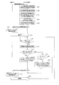
- FIG. 10 is a sequence diagram defining an operation procedure when the radio base station apparatus according to the embodiment of the present invention performs a handover operation optimizing process. It is a figure for demonstrating the difference in the amount of power changes by the transmission power difference between base stations.
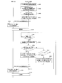
- FIG. 10 is a sequence diagram defining another example of an operation procedure when the radio base station apparatus according to the embodiment of the present invention performs a handover operation optimization process.
- FIG. 10 is a sequence diagram defining another example of an operation procedure when the radio base station apparatus according to the embodiment of the present invention performs a handover operation optimization process.
- FIG. 10 is a sequence diagram defining another example of an operation procedure when the radio base station apparatus according to the embodiment of the present invention performs a handover operation optimization process.
- FIG. 10 is a sequence diagram defining another example of an operation procedure when the radio base station apparatus according to the embodiment of the present invention performs a handover operation optimization process.
- FIG. 10 is a sequence diagram defining another example of an operation procedure when the radio base station
- FIG. 10 is a sequence diagram defining another example of an operation procedure when the radio base station apparatus according to the embodiment of the present invention performs a handover operation optimization process.
- FIG. 10 is a sequence diagram defining another example of an operation procedure when the radio base station apparatus according to the embodiment of the present invention performs a handover operation optimization process.
- FIG. 10 is a sequence diagram defining another example of an operation procedure when the radio base station apparatus according to the embodiment of the present invention performs a handover operation optimization process.
- the radio base station apparatus notifies the radio terminal apparatus of information about the cell and the neighboring cell that it forms, that is, the frequency of the radio signal and the ID (identification) of the neighboring cell.
- the wireless terminal device detects and measures neighboring cells based on information notified from the wireless base station device.
- the wireless terminal device starts moving to the neighboring cell based on the measurement result.
- “movement” of the wireless terminal device means not only handover but also through which cell the wireless terminal device in an idle state starts communication in the future, that is, when a call or data communication is started. This means selecting whether to perform communication.
- the destination of the wireless terminal device is determined by the wireless base station device or the higher-level device in the core network. For example, when the wireless terminal device is not communicating with the wireless base station device, the wireless terminal device determines the destination of the wireless terminal device.
- handover means that a radio base station apparatus that is a communication partner of a radio terminal apparatus during a call or data communication is switched.
- the wireless terminal device is located in a cell means that the wireless terminal device selects a wireless base station device forming the cell as a communication destination and can communicate with the wireless base station device. This means that communication is in progress.
- a femto base station is a customer premises apparatus that connects a wireless terminal device connected via a wireless interface to a mobile communication carrier network using an IP backhaul.
- the femto base station in the closed access mode provides a service only to related CSG (Closed Subscriber Group) members.
- the hybrid mode femto base station also provides services to the associated CSG members and CSG non-members.
- the femto base station in the open access mode operates as a normal base station.
- Such a 3GPP definition may also be applied to the wireless communication system according to the embodiment of the present invention.
- the macro base station and the pico base station are radio base station devices that are under the control of the operator and that can communicate with the radio base station device that has contracted with the operator. Further, it is considered that the macro base station and the pico base station are basically not turned off.
- the femto base station is a radio base station apparatus that is mainly installed in an individual or corporate building and may move or be turned off depending on user circumstances.
- the femto base station operates in an access mode of open / hybrid / closed.
- the closed access mode only registered members (terminals) can be connected.
- the service is provided only to registered members.
- the hybrid mode the service is provided to both registered members and unregistered members, that is, non-members.
- the open access mode the same operation as that of the macro base station and the pico base station is performed.
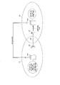
- FIG. 1 is a diagram showing a configuration of a radio communication system according to an embodiment of the present invention.
- the radio communication system is a mobile communication system that complies with LTE (Long Term Evolution) standardized by, for example, 3GPP (Third Generation Partnership Project), and includes radio base station apparatuses 101A and 101B.
- LTE Long Term Evolution
- 3GPP Third Generation Partnership Project
- FIG. 1 two radio base station apparatuses are representatively shown, but a larger number of radio base station apparatuses may be provided.
- Radio base station apparatuses 101A and 101B are, for example, femto base stations, pico base stations, or macro base stations.
- the wireless base station device 101A can communicate with the wireless terminal device 202 by forming a cell CA and transmitting / receiving a wireless signal to / from the wireless terminal device 202 existing in the cell CA.
- the radio base station apparatus 101B can communicate with the radio terminal apparatus 202 by forming a cell CB and transmitting and receiving radio signals to and from the radio terminal apparatus 202 existing in the cell CB.
- the direction from the wireless terminal device to the core network is referred to as an uplink direction
- the direction from the core network to the wireless terminal device is referred to as a downlink direction.
- the radio base station apparatus and the radio terminal apparatus in the radio communication system read and execute a program including each step of the following sequences from a memory (not shown).
- This program can be installed externally.
- the installed program is distributed in a state stored in a recording medium, for example.
- FIG. 2 is a diagram showing an exemplary sequence of a handover operation in the radio communication system according to the embodiment of the present invention.
- the wireless terminal device 202 is located in the cell CA and is in communication with the wireless base station device 101A, and moves to an overlapping area of the cell CA and the cell CB. To do.
- radio base station apparatus 101A sets a frequency to be measured by radio terminal apparatus 202 in communication with itself and another radio base station apparatus that transmits a radio signal of the frequency. (Step S1).
- the wireless base station device 101A sends a measurement start request (Measurement Configuration) to the wireless terminal device 202 to cause the wireless terminal device 202 to measure the reception level of the wireless signal transmitted from the set other wireless base station device.
- This measurement start request includes neighboring cell information, that is, the cell ID of the radio base station apparatus to be measured. Further, the measurement start request includes the transmission frequency of each radio base station device (step S2).
- the wireless terminal device 202 receives the measurement start request from the wireless base station device 101A and starts the power measurement process (Measurement), that is, the wireless indicated by the measurement start request at the frequency indicated by the received measurement start request.
- the received power of the radio signal transmitted from the base station apparatus is measured (step S3).
- the wireless terminal device 202 transmits a measurement result notification (Measurement Report) indicating the measurement result of the received power to the wireless base station device 101A.
- a measurement result notification (Measurement Report) indicating the measurement result of the received power
- the wireless terminal device 202 periodically measures the received power, when the communication state with the wireless base station device 101A deteriorates, and with other wireless base station devices other than the wireless base station device 101A When the state becomes better, a measurement result notification is transmitted to the radio base station apparatus 101A (step S4).
- the radio base station apparatus 101A acquires measurement information indicating the measurement result for each cell ID based on the measurement result notification received from the radio terminal apparatus 202, and stores it in a storage unit (not shown) (step S5).
- the wireless base station device 101A determines whether or not the wireless terminal device 202 should be handed over. For example, the radio base station apparatus 101B is determined as a handover destination with reference to the information (step S6).
- the radio base station device 101A transmits a handover request indicating the radio base station device 101B to the higher-level device (step S7).
- the host apparatus receives the handover request from the radio base station apparatus 101A and transmits the handover request to the radio base station apparatus 101B (step S8).
- the radio base station apparatus 101B receives the handover request from the higher-level apparatus and transmits a handover response to the handover request to the higher-level apparatus (Step S9).
- the higher-level device receives a handover response from the radio base station device 101B and transmits a handover instruction to the radio base station device 101A (step S10).
- the radio base station apparatus 101A receives a handover instruction from the host apparatus and transmits an RRC (Radio Resource Control) connection reconfiguration instruction (RRC Connection Reconfiguration) to the radio terminal apparatus 202 (step S11).
- RRC Radio Resource Control
- the wireless base station device 101A transmits a status notification indicating its own communication status and the like to the higher-level device (step S12).
- the host device receives the status notification from the radio base station device 101A and transmits the status notification indicating the communication content with the radio terminal device 202 to the radio base station device 101B (step S13).
- the wireless terminal device 202 transmits an RRC connection reconfiguration completion notification (RRC Connection Reconfiguration Complete) to the wireless base station device 101B ( Step S14).
- the radio base station apparatus 101B receives the RRC connection reconfiguration completion notification from the radio terminal apparatus 202 and transmits a handover completion notification to the higher-level apparatus (step S15).
- the host device receives a handover completion notification from the radio base station device 101B and transmits a terminal information release instruction to the radio base station device 101A (step S16).
- the wireless base station device 101A receives the terminal information release instruction from the higher-level device, releases the information related to the wireless terminal device 202, and transmits a terminal information release completion notification to the higher-level device (step S17).
- a radio base station apparatus communicating with the radio terminal apparatus 202 or a handover source radio base station apparatus is also referred to as a serving base station, and a handover destination radio base station apparatus is also referred to as a neighboring base station.
- FIG. 3 is a diagram illustrating an example of a situation where an inappropriate handover operation (Too Late HO) occurs in the wireless communication system according to the embodiment of the present invention.
- FIG. 4 is a diagram showing an example of an inappropriate handover operation (Too Late HO) and its detection process sequence in the wireless communication system according to the embodiment of the present invention.
- “Too Late HO” refers to the following cases, for example. That is, before handover starts or during handover processing, a radio link failure (RLF) occurs in the handover source radio base station apparatus, and a radio base station other than the handover source radio base station apparatus. This is a case where connection re-establishment of the wireless terminal device 202 to the device has occurred.
- RLF radio link failure
- the detection method of “Too Late HO” is as follows, for example. That is, when the radio terminal device 202 reestablishes the radio link to the radio base station device 101B after causing the RLF for the radio base station device 101A, the radio base station device 101B notifies the radio base station device 101A of the RLF. Send. Thereby, the radio base station apparatus 101A detects “Too Late HO”.
- the wireless terminal device 202 is located in the cell CA and is communicating with the wireless base station device 101A.
- radio terminal apparatus 202 measures the received power of a radio signal transmitted from each radio base station apparatus, and wirelessly sends a measurement result notification indicating the measured result of the received power. It transmits to base station apparatus 101A (step S51).
- the wireless base station device 101A determines whether or not the wireless terminal device 202 should be handed over.
- the radio base station apparatus 101A refers to the neighboring cell information and determines, for example, the radio base station apparatus 101B as a handover destination (step S52).
- the radio base station apparatus 101A transmits a handover request indicating the radio base station apparatus 101B to the radio base station apparatus 101B via the X2 interface that is an inter-base station interface (step S53).
- the radio base station apparatus 101B receives the handover request from the radio base station apparatus 101A, and transmits a handover response to the handover request to the radio base station apparatus 101A via the X2 interface (step S54).
- the radio terminal apparatus 202 is out of service area of the cell CA, and Move to within the cell CB (step S55).
- step S56 Due to the movement of the wireless terminal device 202, the RRC connection reconfiguration instruction (step S56) for instructing the handover transmitted from the wireless base station device 101A does not reach the wireless terminal device 202, and RLF is generated (step S56). S57).
- the radio terminal apparatus 202 searches for a neighboring radio base station apparatus by measuring the reception power of the radio signal and reconnects to the searched radio base station apparatus 101B.
- a connection re-establishment request (RRC Connection Reestablishment Request) is transmitted (step S58).
- the radio base station apparatus 101B receives the RRC connection re-establishment request from the radio terminal apparatus 202 and transmits an RRC connection re-establishment response to the radio terminal apparatus 202 (step S59). Thereby, an RRC connection is established between the wireless terminal device 202 and the wireless base station device 101B.
- the wireless terminal device 202 transmits an RRC connection re-establishment completion notification (RRC Connection Reestablishment Complete) to the wireless base station device 101B (step S60).
- RRC Connection Reestablishment Complete RRC Connection Reestablishment Complete
- This RRC connection re-establishment completion notification includes a parameter “rlf-InfoAvailable”, for example.
- the wireless terminal device 202 sets this parameter and transmits an RRC connection re-establishment completion notification.
- the radio base station apparatus 101B recognizes that an RLF has occurred in the radio terminal apparatus 202.
- the radio base station apparatus 101B transmits a terminal information request (UE Information Request) to the radio terminal apparatus 202 in order to acquire detailed information of the RLF (step S61).
- UE Information Request terminal information request
- the wireless terminal device 202 receives the terminal information request from the wireless base station device 101B, and transmits a terminal information response (UE Information Response) including the RLF report to the wireless base station device 101B (step S62).
- the RLF report includes the PCI (Physical Cell ID) of the radio base station apparatus in which the RLF has occurred, the PCI and ECGI (E-UTRAN Cell Global Identifier) of the radio base station apparatus in which the RRC connection has been reestablished, and the own radio terminal apparatus 202.
- C-RNTI Cell Radio Network Temporary Identifier
- the PCI of the RLF occurrence is the ID of the radio base station apparatus 101A
- the PCI and ECGI of the RRC connection re-establishment occurrence are the ID of the radio base station apparatus 101B
- the C-RNTI is assigned by the radio base station apparatus 101A ID.
- the radio base station apparatus 101B recognizes that RLF has occurred in the radio base station apparatus 101A by referring to the PCI of the RLF report received from the radio terminal apparatus 202. Then, the radio base station apparatus 101B transmits an RLF notification (RLF INDICATION) including the contents of the RLF report to the radio base station apparatus 101A via the X2 interface in order to notify that it is “Too Late HO” ( Step S63).
- RLF INDICATION an RLF notification including the contents of the RLF report to the radio base station apparatus 101A via the X2 interface in order to notify that it is “Too Late HO”
- the radio base station apparatus 101A recognizes that “Too Late HO” has occurred to the cell CB by referring to the PCI, ECGI, and C-RNTI of the RLF notification received from the radio base station apparatus 101B. (Step S64).
- the radio base station apparatus 101A executes a handover operation optimization process so as to suppress the occurrence of “Too Late HO” in the cell CB (step S65).
- FIG. 5 and 6 are diagrams illustrating an example of a situation where an inappropriate handover operation (Too Early HO) occurs in the wireless communication system according to the embodiment of the present invention.
- cell CB formed by radio base station apparatus 101B includes cell CB1 including the installation area of radio base station apparatus 101B, and radio base station apparatus 101B formed in cell CA.
- the cell CB2 does not include an installation area.
- FIG. 7 is a diagram showing an example of an inappropriate handover operation (Too Early HO) and its detection processing sequence in the wireless communication system according to the embodiment of the present invention.
- “Too Early HO” refers to the following cases, for example. That is, after the wireless terminal device 202 has successfully connected to the handover destination wireless base station device, RLF occurs in a short time, and the wireless terminal device 202 is reconnected to the handover source wireless base station device. This is the case when establishment occurs.
- the detection method of “Too Early HO” is as follows, for example. That is, when the handover destination radio base station apparatus 101B receives the RLF report from the handover source radio base station apparatus 101A, the handover to the radio terminal apparatus 202 itself is performed within a predetermined time from the reception timing. When the terminal information release instruction due to the completion of is transmitted to the radio base station apparatus 101A, the radio base station apparatus 101A is notified that “Too Early HO”.
- the radio base station apparatus 101B uses a timer to measure the predetermined time. As a result, when the radio base station apparatus 101B receives the RLF report, whether the RLF has occurred due to its own “Too Late HO” or whether the RLF has occurred due to the “Too Early HO” of the radio base station apparatus 101A. Can be determined.
- radio terminal apparatus 202 moves into cell CB2 from a state where it is located in cell CA and is communicating with radio base station apparatus 101A (step S70). .
- radio terminal apparatus 202 measures the reception power of a radio signal transmitted from a radio base station apparatus, and sends a measurement result notification indicating the measurement result of the measured reception power to radio base station. It transmits to station apparatus 101A (Source eNB, Serving eNB) (step S71).
- station apparatus 101A Source eNB, Serving eNB
- the wireless base station device 101A determines whether or not the wireless terminal device 202 should be handed over.
- the radio base station apparatus 101A refers to the neighboring cell information and determines, for example, the radio base station apparatus 101B as a handover destination (step S72).
- the radio base station apparatus 101A transmits a handover request indicating the radio base station apparatus 101B to the radio base station apparatus 101B via the X2 interface that is an interface between base stations (step S73).
- the radio base station apparatus 101B receives the handover request from the radio base station apparatus 101A, and transmits a handover response to the handover request to the radio base station apparatus 101A via the X2 interface (step S74).
- the radio base station apparatus 101A receives a handover response from the radio base station apparatus 101B, and transmits an RRC connection reconfiguration instruction (RRC Connection Reconfiguration) to the radio terminal apparatus 202 (step S75).
- RRC Connection Reconfiguration RRC Connection Reconfiguration
- the wireless terminal device 202 transmits an RRC connection reconfiguration completion notification (RRC Connection Reconfiguration Complete) to the wireless base station device 101B. (Step S76).
- the radio base station apparatus 101B receives the RRC connection reconfiguration completion notification from the radio terminal apparatus 202 and transmits a terminal information release instruction to the radio base station apparatus 101A (step S77).
- the radio base station apparatus 101B starts a timer in order to measure the stay time in the cell CB of the radio terminal apparatus 202 (step S78).
- the radio base station apparatus 101A receives a terminal information release instruction from the radio base station apparatus 101B, and releases information (UE Context) on the radio terminal apparatus 202 (step S79).
- step S80 the handover of the wireless terminal device 202 from the wireless base station device 101A to the wireless base station device 101B is completed (step S80).
- the radio terminal apparatus 202 moves outside the cell CB and within the cell CA (step S81).
- step S83 since the wireless terminal device 202 cannot communicate with the wireless base station device 101B, RLF occurs (step S83).
- the radio terminal apparatus 202 searches for a neighboring radio base station apparatus by measuring the reception power of the radio signal and reconnects to the searched radio base station apparatus 101A.
- a connection re-establishment request (RRC Connection Reestablishment Request) is transmitted (step S84).
- the radio base station apparatus 101A since the radio base station apparatus 101A has released and does not hold the information (UE Context) regarding the radio terminal apparatus 202, the radio base station apparatus 101A can accept the RRC connection re-establishment request from the radio terminal apparatus 202. If it is not possible (step S85), an RRC connection re-establishment rejection is transmitted to the wireless terminal device 202 (step S86).
- the radio terminal apparatus 202 when receiving the RRC connection re-establishment rejection from the radio base station apparatus 101A, the radio terminal apparatus 202 starts a normal connection procedure with the radio base station apparatus 101A (step S87).
- the wireless terminal device 202 transmits an RRC connection request to the wireless base station device 101A (step S88).
- the wireless base station device 101A receives the RRC connection request from the wireless terminal device 202, and transmits RRC connection information (RRC Connection Setup) to the wireless terminal device 202 (step S89).
- RRC connection information RRC Connection Setup
- the wireless terminal device 202 receives the RRC connection information from the wireless base station device 101A, and transmits an RRC connection completion notification (RRC Connection Setup Complete) (step S90).
- the wireless base station device 101A receives the RRC connection completion notification from the wireless terminal device 202, and transmits security information (Security Mode Command) to the wireless terminal device 202 (step S91).
- the wireless terminal device 202 receives security information from the wireless base station device 101A, and transmits a security completion notification (Security Mode Complete) to the wireless base station device 101A (step S92).
- the radio base station apparatus 101A transmits an RRC connection reconfiguration instruction (RRC Connection Reconfiguration) to the radio terminal apparatus 202 (step S93).
- RRC Connection Reconfiguration RRC Connection Reconfiguration
- the wireless terminal device 202 transmits an RRC connection reconfiguration completion notification (RRC Connection Reconfiguration Complete) to the wireless base station device 101A. (Step S94).
- the RRC connection completion notification and the RRC connection reconfiguration completion notification include, for example, a parameter “rlf-InfoAvailable”.
- the wireless terminal device 202 sets this parameter and transmits an RRC connection completion notification and an RRC connection reconfiguration completion notification.
- the radio base station apparatus 101A recognizes that an RLF has occurred in the radio terminal apparatus 202.
- the wireless base station device 101A transmits a terminal information request (UE Information Request) to the wireless terminal device 202 in order to acquire detailed information of the RLF (step S95).
- UE Information Request terminal information request
- the wireless terminal device 202 receives the terminal information request from the wireless base station device 101A, and transmits a terminal information response (UE Information Response) including the RLF report to the wireless base station device 101A (step S96).
- the RLF report includes the PCI of the radio base station apparatus in which the RLF has occurred, the PCI and ECGI of the radio base station apparatus in which the RRC connection re-establishment has occurred, and the C-RNTI of the own radio terminal apparatus 202.
- the PCI of the RLF occurrence is the ID of the radio base station apparatus 101B
- the PCI and ECGI of the RRC connection re-establishment are the ID of the radio base station apparatus 101A
- the C-RNTI is assigned by the radio base station apparatus 101B ID.
- the radio base station apparatus 101A recognizes that RLF has occurred in the radio base station apparatus 101B by referring to the PCI of the RLF report received from the radio terminal apparatus 202, and performs “Too Late HO” to the cell CA. "Is generated (step S97).
- the radio base station apparatus 101A transmits an RLF notification (RLF INDICATION) including the content of the RLF report to the radio base station apparatus 101B via the X2 interface in order to notify that it is “Too Late HO”. (Step S98).
- the radio base station apparatus 101B checks the timer that has been started. If the timer is operating, that is, a predetermined time has elapsed since the timer was started. If not, it is determined not to be “Too Late HO” to the cell CA but to “Too Early HO” to the cell CB.
- the radio base station apparatus 101B receives the RLF notification from the radio base station apparatus 101A and the timer is not operating, that is, when the predetermined time has elapsed since the timer was started, the cell CA It is determined that it is “Too Late HO”.
- the radio base station apparatus 101B determines that it is “Too Early HO” to the cell CB (step S99), it transmits a handover report to the radio base station apparatus 101A (step S100).
- This handover report includes, for example, a parameter “Handover Report Type”.
- the radio base station apparatus 101B notifies the radio base station apparatus 101A of “Too Early HO” by setting this parameter to a predetermined value.
- the radio base station apparatus 101A receives the handover report from the radio base station apparatus 101B, recognizes that “Too Early HO” has occurred to the cell CB (step S101), and “Too Early HO”. A handover operation optimization process is executed so as to suppress the occurrence of (step S102).
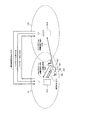
- FIG. 8 is a diagram illustrating an example of a situation in which an inappropriate handover operation (HO to Wong Cell) occurs in the wireless communication system according to the embodiment of the present invention.
- the wireless communication system further includes a wireless base station device 101 ⁇ / b> C as compared with the wireless communication system illustrated in FIG. 1.
- Radio base station apparatus 101C is, for example, a femto base station, a pico base station, or a macro base station.
- the radio base station apparatus 101C can communicate with the radio terminal apparatus 202 by forming a cell CC and transmitting and receiving radio signals to and from the radio terminal apparatus 202 existing in the cell CC.
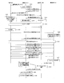
- FIG. 9 is a diagram showing an example of an improper handover operation (HO to Wong Cell) and its detection processing sequence in the wireless communication system according to the embodiment of the present invention.
- HO to Wong Cell refers to the following cases, for example. That is, after the wireless terminal device 202 has successfully connected to the handover destination wireless base station device, RLF occurs in a short time, and wireless communication is performed with respect to wireless base station devices other than the handover source and handover destination wireless base station devices. This is a case where the connection re-establishment of the terminal device 202 occurs.
- the detection method of “HO to Wong Cell” is as follows. That is, when the radio base station apparatus 101B that is the handover destination receives the RLF report from the radio base station apparatus 101C other than the radio base station apparatus 101A that is the handover source, the radio terminal is traced back from the reception timing within a predetermined time. When the terminal information release instruction due to the completion of the handover of the apparatus 202 to itself is transmitted to the radio base station apparatus 101A, the radio base station apparatus 101A is notified that “HO to Wong Cell”.
- the radio base station apparatus 101B uses a timer to measure the predetermined time. Thereby, when the radio base station apparatus 101B receives the RLF report, whether the RLF has occurred due to its own “Too Late HO” or whether the RLF has occurred due to the “HO to Wong Cell” of the radio base station apparatus 101A. Can be determined.
- the wireless terminal device 202 when the wireless terminal device 202 is located in the cell CA and is communicating with the wireless base station device 101A, the wireless terminal device 202 moves to the overlapping area of the virtual cell CBV and the cell CA ( Assume step S110).
- the virtual cell CBV is a virtual cell expanded from the cell CB in accordance with the offset OST that is a parameter in order to promote handover from the radio base station apparatus 101A to the radio base station apparatus 101B.
- the offset OST is a parameter held by the radio base station apparatus 101A.
- radio terminal apparatus 202 measures the received power of a radio signal transmitted from the radio base station apparatus, and sends a measurement result notification indicating the measured result of the received power to radio base station. Transmit to the station apparatus 101A (step S111).
- the wireless base station device 101A determines whether or not the wireless terminal device 202 should be handed over.
- the radio base station apparatus 101A refers to the neighboring cell information and determines, for example, the radio base station apparatus 101B as a handover destination (step S112).
- the radio base station apparatus 101A transmits a handover request indicating the radio base station apparatus 101B to the radio base station apparatus 101B via the X2 interface that is an interface between base stations (step S113).
- the radio base station apparatus 101B receives the handover request from the radio base station apparatus 101A, and transmits a handover response to the handover request to the radio base station apparatus 101A via the X2 interface (step S114).
- the radio base station apparatus 101A receives a handover response from the radio base station apparatus 101B, and transmits an RRC connection reconfiguration instruction (RRC Connection Reconfiguration) to the radio terminal apparatus 202 (step S115).
- RRC Connection Reconfiguration RRC Connection Reconfiguration
- the wireless terminal device 202 transmits an RRC connection reconfiguration completion notification (RRC Connection Reconfiguration Complete) to the wireless base station device 101B. (Step S116).
- the radio base station apparatus 101B receives the RRC connection reconfiguration completion notification from the radio terminal apparatus 202, and transmits a terminal information release instruction to the radio base station apparatus 101A (step S117).
- the radio base station apparatus 101B starts a timer in order to measure the staying time in the cell CB of the radio terminal apparatus 202 (step S118).
- the radio base station apparatus 101A receives a terminal information release instruction from the radio base station apparatus 101B, and releases information (UE Context) on the radio terminal apparatus 202 (step S119).
- step S120 the handover of the wireless terminal device 202 from the wireless base station device 101A to the wireless base station device 101B is completed (step S120).
- the radio terminal apparatus 202 moves out of the cell CB and into the virtual cell CBV and the cell CC (step S121).
- the radio terminal device 202 has a large interference of radio signals transmitted from the radio base station device 101C (Other eNB), and cannot communicate with the radio base station device 101B, so that RLF occurs (step S123). .
- the radio terminal apparatus 202 searches for nearby radio base station apparatuses by measuring the reception power of radio signals or the like. In this case, since the reception power of the radio signal from the radio base station apparatus 101C is maximized, the radio terminal apparatus 202 receives an RRC connection re-establishment request (RRC Connection) in order to reconnect to the searched radio base station apparatus 101C. Reestablishment Request) is transmitted to the radio base station apparatus 101C (step S124).
- RRC Connection RRC Connection
- the wireless base station device 101C since the wireless base station device 101C does not hold information (UE Context) regarding the wireless terminal device 202, the wireless base station device 101C cannot accept the RRC connection re-establishment request from the wireless terminal device 202 (step S125). ), RRC connection re-establishment rejection is transmitted to the wireless terminal device 202 (step S126).
- UE Context information regarding the wireless terminal device 202
- the radio terminal apparatus 202 receives an RRC connection re-establishment rejection from the radio base station apparatus 101C, and starts a normal connection procedure with the radio base station apparatus 101C (step S127).
- the wireless terminal device 202 transmits an RRC connection request to the wireless base station device 101C (step S128).
- the wireless base station device 101C receives the RRC connection request from the wireless terminal device 202, and transmits RRC connection information (RRC Connection Setup) to the wireless terminal device 202 (step S129).
- RRC connection information RRC Connection Setup
- the wireless terminal device 202 receives RRC connection information from the wireless base station device 101C, and transmits an RRC connection completion notification (RRC Connection Setup Complete) (step S130).
- the wireless base station device 101C receives the RRC connection completion notification from the wireless terminal device 202, and transmits security information (Security Mode Command) to the wireless terminal device 202 (step S131).
- the wireless terminal device 202 receives security information from the wireless base station device 101C, and transmits a security completion notification (Security Mode Complete) to the wireless base station device 101C (step S132).
- the wireless base station device 101C transmits an RRC connection reconfiguration instruction (RRC Connection Reconfiguration) to the wireless terminal device 202 (step S133).
- RRC Connection Reconfiguration RRC Connection Reconfiguration
- the wireless terminal device 202 transmits an RRC connection reconfiguration completion notification (RRC Connection Reconfiguration Complete) to the wireless base station device 101C. (Step S134).
- the RRC connection completion notification and the RRC connection reconfiguration completion notification include, for example, a parameter “rlf-InfoAvailable”.
- the wireless terminal device 202 sets this parameter and transmits an RRC connection completion notification and an RRC connection reconfiguration completion notification. Thereby, the radio base station apparatus 101C recognizes that an RLF has occurred in the radio terminal apparatus 202.
- the wireless base station device 101C transmits a terminal information request (UE Information Request) to the wireless terminal device 202 in order to acquire detailed information of the RLF (step S135).
- UE Information Request terminal information request
- the wireless terminal device 202 receives a terminal information request from the wireless base station device 101C, and transmits a terminal information response (UE Information Response) including an RLF report to the wireless base station device 101C (step S136).
- the RLF report includes the PCI of the radio base station apparatus in which the RLF has occurred, the PCI and ECGI of the radio base station apparatus in which the RRC connection re-establishment has occurred, and the C-RNTI of the own radio terminal apparatus 202.
- the PCI of the RLF occurrence is the ID of the radio base station apparatus 101B
- the PCI and ECGI of the RRC connection re-establishment are the ID of the radio base station apparatus 101C
- the C-RNTI is assigned by the radio base station apparatus 101B ID.
- the wireless base station device 101C recognizes that RLF has occurred in the wireless base station device 101B by referring to the PCI of the RLF report received from the wireless terminal device 202, and performs “Too Late HO” to the cell CC. "Is generated (step S137).
- the radio base station apparatus 101C transmits an RLF notification (RLF INDICATION) including the content of the RLF report to the radio base station apparatus 101B via the X2 interface in order to notify that it is “Too Late HO”. (Step S138).
- the radio base station apparatus 101B checks the timer that has been started. If the timer is operating, that is, a predetermined time has elapsed since the timer was started. If not, it is determined that it is not “Too Late HO” to the cell CC, and further, the RLF notification is received from the radio base station device 101C other than the radio base station device 101A. It is determined that it is not “Too Early HO” but “HO to Wron Cell” to the cell CB.
- the radio base station apparatus 101B When the radio base station apparatus 101B receives the RLF notification from the radio base station apparatus 101C and the timer is not operating, that is, when the predetermined time has elapsed since the timer was started, the cell CC It is determined that it is “Too Late HO”.
- the radio base station apparatus 101B determines that it is “HO to Wong Cell” to the cell CB (step S139), it transmits a handover report to the radio base station apparatus 101A (step S140).
- This handover report includes, for example, a parameter “Handover Report Type”.
- the radio base station apparatus 101B notifies the radio base station apparatus 101A of “HO to Wong Cell” by setting this parameter to a predetermined value.
- the radio base station apparatus 101A receives the handover report from the radio base station apparatus 101B, recognizes that “HO to Wong Cell” has occurred to the cell CB (step S141), and performs “HO to Wong”.
- the optimization process of the handover operation is executed so that the occurrence of “Cell” is suppressed (step S142).
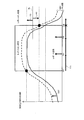
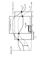
- FIG. 10 is a diagram showing a simulation result of reception quality of the wireless terminal device in the wireless communication system according to the embodiment of the present invention.
- FIG. 10 shows an RSSI (Received Signal Strength Indication) of the wireless terminal device 202 for 100 seconds until the wireless terminal device 202 passes near the pico base station at a speed of 30 km per hour and passes near the macro base station.
- RSSI Received Signal Strength Indication
- graphs G1 and G3 indicate RSSIs of radio signals transmitted from the macro base station
- graphs G2 and G4 indicate RSSIs of radio signals transmitted from the pico base station.
- the graphs G1 and G2 take into account the temporal change in the received power of the radio signal in the radio terminal device 202 caused by shadowing, that is, the relative position change between the radio terminal device 202 and other objects. Simulation results, and graphs G3 and G4 are simulation results that do not consider shadowing.
- the ideal position for handover of the wireless terminal device 202 from the pico base station to the macro base station is the vicinity of the intersection of the graph, that is, the position where the movement time is about 17 seconds.
- Y MRO (X)
- Y is, for example, the occurrence frequency of “Too Late HO”, “Too Early HO” “Occurrence frequency”, “HO to Wong Cell” occurrence frequency, “Ping Pong HO” unnecessary handover occurrence frequency, etc.
- the radio terminal device 202 connects to the radio base station device This is the frequency of occurrence of handover immediately after being performed.
- X is a parameter for power measurement processing (Measurement), hysteresis HS: 0 dB to +15 dB, TTT (Time to Trigger): 0 ms to 5120 ms, or offset OST (Cell Individual Offset): ⁇ 24 dB to +24 dB It is.
- X is a parameter for cell reselection processing.
- the hysteresis HS and TTT can be set for each event described later
- the offset OST can be set for each serving cell formed by the serving base station and each neighboring cell
- the gap MG and the filtering coefficient ⁇ described later can be set for each serving cell. It can be set.
- the wireless base station device determines handover when receiving a measurement result notification (Measurement Report). That is, the transmission timing of the measurement result notification corresponds to the handover timing.
- FIG. 11 is a diagram showing an event A1 in which the wireless terminal device transmits a measurement result notification in the wireless communication system according to the embodiment of the present invention.
- the horizontal axis is time
- the vertical axis is the reception power or SINR of the radio signal in the wireless terminal device 202
- the SVC is the reception power or SINR of the serving cell, that is, the reception power of the radio signal transmitted by the serving base station or SINR.
- hysteresis HS is set in a positive or negative direction with respect to threshold value Th.
- the wireless terminal device 202 transitions to the report on state (timing T1).
- the wireless terminal device 202 transmits a measurement result notification (timing T2).
- the wireless terminal device 202 transmits a measurement result notification (timing T3).
- timing T4 the wireless terminal device 202 does not transmit a measurement result notification and transitions to a report off state (timing T4).
- the wireless terminal device 202 performs a power measurement process periodically, for example, regardless of the transition between the report-on state and the report-off state, and transmits the latest measurement result as a measurement result notification. Further, for example, radio terminal apparatus 202 performs transition between the report-on state and the report-off state independently for each of received power and SINR. That is, the wireless terminal device 202 transmits a measurement result notification if a condition is satisfied for one of the received power and SINR.
- FIG. 12 is a diagram showing an event A2 in which the wireless terminal device transmits a measurement result notification in the wireless communication system according to the embodiment of the present invention. The way of viewing the figure is the same as in FIG.
- hysteresis HS is set in a positive or negative direction with respect to threshold value Th.
- the wireless terminal device 202 transitions to the report on state (timing T11).
- the wireless terminal device 202 transmits a measurement result notification when TTT elapses from timing T11 in a state where the condition that the received power or SINR is smaller than (Th + HS) is satisfied (timing T12).
- the wireless terminal device 202 transmits a measurement result notification (timing T13).
- the wireless terminal device 202 does not transmit a measurement result notification and transitions to a report off state (timing T14).
- FIG. 13 is a diagram showing an event A3 in which the wireless terminal device transmits a measurement result notification in the wireless communication system according to the embodiment of the present invention.
- the horizontal axis is time
- the vertical axis is the reception power or SINR of the radio signal in the wireless terminal device 202
- SVC is the reception power or SINR of the serving cell
- NBC is the reception power or SINR of the neighboring cell, that is, This is the reception power or SINR of a radio signal transmitted by a neighboring base station.
- offset OST1 is set in the positive direction with respect to the reception power or SINR of the serving cell, and hysteresis HS is set in the positive and negative directions. Also, the offset OST2 is set in the positive direction with respect to the reception power or SINR of the neighboring cells.
- the wireless terminal device 202 transitions to the report-on state when ⁇ (reception power or SINR of neighboring cells) + OST2 ⁇ becomes larger than ⁇ (reception power or SINR of the serving cell) + OST1 + HS ⁇ (timing T21).
- the wireless terminal device 202 performs the processing from the timing T21 to the TTT in a state where ⁇ (neighboring cell received power or SINR) + OST2 ⁇ is larger than ⁇ (serving cell received power or SINR) + OST1-HS ⁇ .
- a measurement result notification is transmitted (timing T22).
- the wireless terminal device 202 transmits a measurement result notification (timing T23).
- the wireless terminal device 202 does not transmit a measurement result notification and transitions to a report off state (timing T24).
- FIG. 14 is a diagram showing an event A4 in which the wireless terminal device transmits a measurement result notification in the wireless communication system according to the embodiment of the present invention. The way of viewing the figure is the same as in FIG.
- the offset OST is set in the positive direction with respect to the reception power or SINR of the neighboring cells, and the hysteresis HS is set in the positive and negative directions with respect to the threshold Th.
- Wireless terminal apparatus 202 transitions to a report-on state when ⁇ (reception power or SINR of neighboring cells) + OST ⁇ is greater than (Th + HS) (timing T31).
- wireless terminal apparatus 202 transmits a measurement result notification when TTT elapses from timing T31 while the condition that ⁇ (reception power or SINR of the neighboring cell) + OST ⁇ is larger than (Th ⁇ HS) is satisfied. (Timing T32).
- the wireless terminal device 202 transmits a measurement result notification (timing T33).
- the wireless terminal device 202 does not transmit a measurement result notification and transitions to a report off state (timing T34).
- FIG. 15 is a diagram showing an event A5 in which the wireless terminal device transmits a measurement result notification in the wireless communication system according to the embodiment of the present invention. The way of viewing the figure is the same as in FIG.
- the offset OST is set in the positive direction with respect to the reception power or SINR of the neighboring cell, and the hysteresis HS1 is set in the positive and negative direction with respect to the threshold Th1.
- Hysteresis HS2 is set in the positive and negative directions with respect to Th2.
- the wireless terminal device 202 transitions to the report on state. (Timing T41).
- Radio terminal 202 satisfies the condition that the reception power or SINR of the serving cell is smaller than (Th1 + HS1) and ⁇ (reception power or SINR of the neighboring cell) + OST ⁇ is larger than (Th2-HS2).
- TTT elapses from timing T41 in a state where it is in a state, a measurement result notification is transmitted (timing T42).
- the wireless terminal device 202 does not transmit a measurement result notification and transitions to a report off state (timing T43).
- the timing of the handover operation of the wireless terminal device 202 can be controlled by adjusting the parameters described in the events A1 to A5, that is, the hysteresis HS, TTT, and the offset OST.
- FIG. 16 is a diagram showing timing control of the handover operation by adjusting the hysteresis HS in the wireless communication system according to the embodiment of the present invention.
- FIG. 16 shows the case of event A3.
- hysteresis HS when hysteresis HS is set to zero, a transition is made to the report on state at timing T51, a measurement result notification is transmitted at timing T53, and a transition to the report off state is made at timing T55.
- the state transits to the report-on state at timing T52 after timing T51, the measurement result notification is transmitted at timing T54 after timing T53, and timing T55. At a later timing T56, the state transits to the report off state.
- the transmission timing of the measurement result notification that is, the timing of the handover operation can be delayed.
- FIG. 17 is a diagram showing handover operation timing control by adjusting TTT in the wireless communication system according to the embodiment of the present invention.
- FIG. 17 shows the case of event A3.
- the transmission timing of the measurement result notification that is, the timing of the handover operation can be delayed.
- FIG. 18 is a diagram showing handover operation timing control by adjusting the offset OST in the wireless communication system according to the embodiment of the present invention.
- FIG. 18 shows the case of event A3.
- the transmission timing of the measurement result notification that is, the timing of the handover operation can be delayed. Further, the transition from the report off state to the report on state is delayed, and the transition from the report on state to the report off state is accelerated.
- the timing of the handover operation is delayed by increasing the hysteresis HS, increasing the TTT, or decreasing the offset OST. That is, since the time for which the wireless terminal device 202 is connected to the serving base station becomes longer, the occurrence frequency of “Too Early HO”, “HO to Wong Cell” and “Ping Pong HO” is reduced, and “Too Late HO” The frequency of occurrence will increase.
- the handover timing can be adjusted by adjusting any of the parameters, but these effects differ depending on the topography including interference, the moving speed of the wireless terminal device, and the like.
- Adjusting the hysteresis HS and the offset OST corresponds to adjusting the position where the handover is performed by virtually increasing or decreasing the cell. For example, by increasing the hysteresis HS of the serving cell, the received power of the radio signal is increased and the handover to another cell is difficult to be performed. Also, by setting the offset OST of the neighboring cell to a negative value, the received power of the radio signal from the neighboring cell appears to be small, and handover to another cell is difficult to be performed.
- the hysteresis HS and the offset OST are parameters that are not easily influenced by the moving speed of the wireless terminal device.
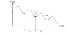
- FIG. 19 is a diagram illustrating an example of received power of a radio signal at each position in the radio communication system according to the embodiment of the present invention.
- the timing of the handover operation by adjusting the hysteresis HS at the positions P1, P3, and P5 where the received power is at the maximum value. Further, it is preferable to adjust the timing of the handover operation by adjusting the offset OST at the positions P2, P4, and P6 at which the received power becomes the minimum value.
- TTT is a parameter that can delay the timing of the handover operation in the time domain.
- the timing of the handover operation does not depend on the radio wave environment and the landform, but the position where the handover is performed varies greatly depending on the moving speed of the wireless terminal device 202. For example, if the TTT is set too large, a wireless terminal device that moves at high speed is likely to fail in handover because the surrounding radio wave environment changes greatly.
- FIG. 20 is a diagram for explaining another example of parameters for controlling the timing of the handover operation in the wireless communication system according to the embodiment of the present invention.
- radio terminal apparatus 202 measures received power of a radio signal transmitted from a radio base station apparatus, for example, at a time interval of gap MG.
- the gap MG When the gap MG is increased, the received power of the past is used for the handover determination, so the timing of the handover operation is delayed. On the other hand, when the gap MG is made smaller, the more recent received power is used for the handover decision, so the timing of the handover operation is advanced.
- the gap MG By reducing the gap MG, it is possible to perform an appropriate handover based on more recent received power. On the other hand, by increasing the gap MG, the processing load on the wireless terminal device 202 can be reduced.
- the wireless terminal device 202 transmits a measurement result notification indicating the received power MR (t) to the wireless base station device.
- the filtering coefficient ⁇ When the filtering coefficient ⁇ is increased, the past received power is reflected in the measurement result notification, so the timing of the handover operation is delayed. On the other hand, when the filtering coefficient ⁇ is reduced, the more recent received power is reflected in the measurement result notification, so that the timing of the handover operation is advanced.
- an offset OST is set for each neighboring cell, and the event At least one of A1 to A5 is set, and hysteresis HS and TTT corresponding to the set event are set.
- the gap MG and the filtering coefficient ⁇ are set for each serving cell.
- FIG. 21 is a diagram showing a configuration of a radio base station apparatus according to the embodiment of the present invention.
- radio base station apparatus 101 includes antenna 91, circulator 92, radio reception unit 93, radio transmission unit 94, signal processing unit 95, and control unit 98.
- the signal processing unit 95 includes a reception signal processing unit 96 and a transmission signal processing unit 97.
- the signal processing unit 95 and the control unit 98 are realized by a CPU (Central Processing Unit) or a DSP (Digital Signal Processor).
- the circulator 92 outputs the radio signal from the radio terminal device 202 received by the antenna 91 to the radio reception unit 93 and outputs the radio signal received from the radio transmission unit 94 to the antenna 91.
- the radio reception unit 93 converts the frequency of the radio signal received from the circulator 92 into a baseband signal or IF (Intermediate Frequency) signal, converts the frequency-converted signal into a digital signal, and outputs the digital signal to the reception signal processing unit 96.
- IF Intermediate Frequency
- the reception signal processing unit 96 performs signal processing such as despreading in the CDMA (Code Division Multiple Access) system on the digital signal received from the wireless reception unit 93, and performs part or all of the digital signal after this signal processing.
- the data is converted into a predetermined frame format and transmitted to the core network side.
- the transmission signal processing unit 97 uses IFFT (Inverse Fast Fourier Transform) in the OFDM (Orthogonal Frequency Division Multiplex) method for communication data obtained by converting communication data received from the core network side into a predetermined frame format or communication data generated by itself.
- IFFT Inverse Fast Fourier Transform
- OFDM Orthogonal Frequency Division Multiplex
- the wireless transmission unit 94 converts the digital signal received from the transmission signal processing unit 97 into an analog signal, converts the frequency of the converted analog signal into a wireless signal, and outputs the converted signal to the circulator 92.
- the control unit 98 exchanges various types of information with each unit and the core network in the radio base station apparatus 101.
- FIG. 22 is a diagram showing a configuration of a control unit in the radio base station apparatus according to the embodiment of the present invention.
- control unit 98 includes terminal power information acquisition unit 11, handover control unit (mobile operation control unit) 12, terminal power estimation unit 13, base station measurement unit 14, and terminal measurement result acquisition. Unit 15 and an inter-base station distance estimation unit 16.
- the terminal power information acquisition unit 11 determines the degree of change of the received power of the radio signal in the radio terminal apparatus 202 located in the cell formed by its own radio base station apparatus with respect to the position change of the radio terminal apparatus 202 (hereinafter referred to as power change amount).
- Terminal power information indicating PC is acquired.
- the degree of change may be expressed as a degree such as “large” or “small”, or may be expressed numerically.
- the terminal power information acquisition unit 11 transmits a wireless signal transmitted from its own wireless base station device in the wireless terminal device 202. It is preferable to obtain an index indicating the received quality, for example, a power change amount PC in a state where SINR is a predetermined value or less. Alternatively, the terminal power information acquisition unit 11 acquires terminal power information indicating the power change amount PC in a state where the reception power of the radio signal transmitted by another radio base station apparatus is equal to or greater than a predetermined value in the radio terminal apparatus 202. A configuration is preferred.
- the handover control unit 12 controls the timing of the handover operation of the radio terminal device 202 from its own radio base station device to another radio base station device. .
- the handover control unit 12 performs control so that the timing of the handover operation is advanced when the power change amount PC indicated by the terminal power information is large, and when the power change amount PC is small, Control the timing to be delayed.
- the handover control unit 12 sets the timing control width of the handover operation, that is, the parameter change width to be large, and when the power change amount PC is small, the handover control unit 12 Set the operation timing control width small.
- the handover control unit 12 outputs control information indicating the set parameters to the transmission signal processing unit 97.
- the transmission signal processing unit 97 includes the parameter indicated by the control information received from the handover control unit 12 in the communication data and outputs the communication data to the wireless transmission unit 94.
- the base station measurement unit 14 Based on the radio signal received by the radio reception unit 93, the base station measurement unit 14 receives the radio signal reception power and frequency received from the radio terminal device 202, and the radio signal reception power transmitted by other radio base station devices. Measure etc.
- the inter-base station distance estimation unit 16 receives a transmission power of a radio signal transmitted from another radio base station apparatus and a radio signal transmitted from the other radio base station apparatus in a cell formed by the own radio base station apparatus. Based on the downlink path loss that is the difference from the power, the inter-base station distance R between the own radio base station apparatus and another radio base station apparatus is estimated.
- the terminal measurement result acquisition unit 15 uses the signal processing result of the reception signal processing unit 96 to acquire the measurement result notification transmitted by the wireless terminal device 202.
- the inter-base station distance estimation unit 16 refers to the measurement result notification acquired by the terminal measurement result acquisition unit 15, for example, so that the radio signal from another radio base station device in the cell formed by the own radio base station device is transmitted. Get received power. Note that the inter-base station distance estimation unit 16 replaces the received power indicated by the measurement result notification with another radio base station measured by the base station measurement unit 14 when the cell radius of its own radio base station device is small.
- the configuration may be such that the reception power of the radio signal from the device is acquired.
- the terminal power estimation unit 13 estimates the power change amount PC based on the inter-base station distance R estimated by the inter-base station distance estimation unit 16.
- the terminal power information acquisition unit 11 acquires the power change amount PC estimated by the terminal power estimation unit 13 as terminal power information.
- the terminal power estimation unit 13 estimates the power change amount PC based on the transmission power difference PD of radio signals transmitted from the own radio base station apparatus and other radio base station apparatuses.
- the terminal power estimation unit 13 estimates the power change amount PC based on the moving speed of the wireless terminal device 202 located in the cell formed by the own wireless base station device.
- the moving speed of the wireless terminal device 202 means a physical moving speed of the wireless terminal device 202, for example, speed [km / h].
- the terminal power estimation unit 13 receives the transmission power of a radio signal transmitted from another radio base station apparatus and the radio signal transmitted from the other radio base station apparatus in a cell formed by the own radio base station apparatus.
- the power change amount PC is estimated based on the temporal change of the downlink path loss, which is the difference from the power.
- the terminal power estimation unit 13 transmits the transmission power of the radio signal transmitted from the wireless terminal device 202 located in the cell formed by the own radio base station device and the received power of the radio signal in the own radio base station device.
- the power change amount PC is estimated based on the temporal change in the uplink path loss, which is the difference between the two.
- the terminal power estimation unit 13 may transmit the frequency of the radio signal transmitted by the radio terminal device 202 located in the cell formed by the own radio base station device and the frequency of the radio signal received by the own radio base station device.
- the power change amount PC is estimated based on the Doppler shift that is the difference between the two.
- the terminal power estimation unit 13 estimates the power change amount PC based on shadowing that is a temporal change in the received power of the radio signal in the wireless terminal device 202.
- the terminal power estimation unit 13 refers to the measurement result notification acquired by the terminal measurement result acquisition unit 15 to receive a radio signal in the radio terminal device 202 located in the cell formed by the own radio base station device. A temporal change in received power is acquired based on the power measurement result.
- the terminal power estimation unit 13 changes temporally the received power of the wireless terminal device 202 having a high moving speed among the plurality of wireless terminal devices 202 located in the cell formed by the own wireless base station device. Is used to estimate the power change amount PC.
- the components surrounded by a broken line in FIG. 22, that is, the terminal power estimation unit 13, the base station measurement unit 14, the terminal measurement result acquisition unit 15, and the inter-base station distance estimation unit 16 are essential components in the present invention. is not. Even if the radio base station apparatus 101 does not include these components, it is possible to achieve the object of the present invention to stabilize communication by appropriately controlling the movement operation of the radio terminal apparatus. .
- the timing control of the handover operation of the wireless terminal device 202 from the self to the macro base station by the femto base station will be described, but the type of the base station is not limited to this example, and other combinations It may be.
- FIG. 23 is a diagram for explaining the difference in the amount of power change due to the distance between base stations.
- the horizontal axis represents the position of the wireless terminal device 202
- the vertical axis represents the reception power of the wireless signal in the wireless terminal device 202.
- the transmission powers of cells C1 to C3 are equal.
- the power change amount PC is larger than the cell edge CEG2 of the cell C1 and the cell C3 whose peak positions are separated by the distance D2 larger than the distance D1.
- the radio base station apparatus performs parameter adjustment using this relationship, for example.
- FIG. 24 is a sequence diagram that defines an operation procedure when the radio base station apparatus according to the embodiment of the present invention performs an optimization process of a handover operation.
- radio terminal apparatus 202 measures the reception power of a radio signal transmitted from each radio base station apparatus, and sends a measurement result notification indicating the measurement result of the measured reception power to the femto base station. Transmit (step S161).
- the femto base station acquires the received power of the wireless signal transmitted by itself from the wireless terminal device 202 based on the measurement result notification received from the wireless terminal device 202 (step S162).
- the femto base station acquires the transmission power of the radio signal of the macro base station. For example, the femto base station acquires the transmission power value included in the broadcast information received from the macro base station, or acquires the transmission power value set in advance by the user (step S163).
- the femto base station obtains a downlink path loss that is a difference between the transmission power of the radio signal of the macro base station and the reception power of the radio signal in the radio terminal device 202. Then, the femto base station calculates the inter-base station distance R between itself and the macro base station based on the downlink path loss (step S164).
- the femto base station estimates the power change amount PC at the cell edge between the femto cell and the macro cell formed by itself. For example, the femto base station determines that the power change amount PC is small when the inter-base station distance R is larger than a predetermined threshold, and the power change amount PC is smaller when the inter-base station distance R is smaller than the predetermined threshold. It is determined that it is large (step S165).
- the femto base station sets the parameters for the handover operation according to the estimated power change amount PC. For example, the femto base station sets parameters so that the timing of the handover operation is delayed when the power change amount PC is small. Specifically, the hysteresis HS is increased, the TTT is increased, the offset OST is decreased, the gap MG is increased, or the filtering coefficient ⁇ is increased. On the other hand, the femto base station sets parameters so that the timing of the handover operation is advanced when the power change amount PC is large. Specifically, the hysteresis HS is decreased, the TTT is decreased, the offset OST is increased, the gap MG is decreased, or the filtering coefficient ⁇ is decreased (step S166).
- the femto base station transmits an RRC connection reconfiguration instruction (RRC Connection Reconfiguration) including the newly set parameters to the wireless terminal device 202.
- RRC Connection Reconfiguration RRC Connection Reconfiguration
- the wireless terminal device 202 that is the transmission destination of the RRC connection reconfiguration instruction is not limited to the wireless terminal device 202 that is the transmission source of the measurement result notification, but is a wireless terminal device 202 that is located in a cell formed by the femto base station. It only has to be present (step S167).
- radio terminal apparatus 202 measures the received power of the radio signal transmitted from each radio base station apparatus and transmits a measurement result notification according to the new setting parameter indicated by the RRC connection reconfiguration instruction received from the femto base station. Is performed (step S168). Further, normal operation is performed in the wireless communication system (step S169).
- step S170 when the femto base station detects an abnormal handover of “Too Late HO”, “Too Early HO”, “HO to Wong Cell” or “Ping Pong HO” (YES in step S170), the detected abnormal handover is detected.
- the occurrence frequency is updated (step S171).
- the femto base station determines that the occurrence frequency EF of “Too Early HO”, the occurrence frequency WF of “HO to Wong Cell”, or the occurrence frequency PF of “Ping Pong HO” is higher than a predetermined threshold ThE, ThW, or ThP. If larger (YES in step S172), the parameter is set so that the timing of the handover operation is delayed, and the control width of the parameter, that is, the step size is set according to the estimated power change amount PC. For example, the femto base station sets the step size small when the power change amount PC is small, and sets the step size large when the power change amount PC is large.
- the femto base station when the occurrence frequency EF, the occurrence frequency WF, or the occurrence frequency PF is smaller than a predetermined threshold ThE, ThW, or ThP (NO in step S172), the occurrence frequency of “Too Late HO” When LF is larger than a predetermined threshold ThL (YES in step S174), the parameter is set so that the timing of the handover operation is advanced, and the control width of the parameter, that is, the step size according to the estimated power change amount PC Set. For example, the femto base station sets the step size small when the power change amount PC is small, and sets the step size large when the power change amount PC is large.
- the femto base station transmits an RRC connection reconfiguration instruction (RRC Connection Reconfiguration) including the newly set parameters to the wireless terminal device 202.
- RRC Connection Reconfiguration RRC Connection Reconfiguration
- the wireless terminal device 202 that is the transmission destination of the RRC connection reconfiguration instruction is not limited to the wireless terminal device 202 that is the transmission source of the measurement result notification, but is a wireless terminal device 202 that is located in a cell formed by the femto base station. It only has to be present (step S176).
- radio terminal apparatus 202 measures the received power of the radio signal transmitted from each radio base station apparatus and transmits a measurement result notification according to the new setting parameter indicated by the RRC connection reconfiguration instruction received from the femto base station. Is performed (step S177). Then, normal operation is performed in the wireless communication system (step S178).
- FIG. 25 is a diagram for explaining a difference in power change amount due to a difference in transmission power between base stations. The way of viewing the figure is the same as in FIG.
- the distance between cells C1 and C2 is equal to the distance between cells C1 and C4.
- the power change amount PC is larger than the cell edge CEG1 of the cell C1 and the cell C2 where the transmission power difference is zero.
- the radio base station apparatus performs parameter adjustment using this relationship, for example.
- FIG. 26 is a sequence diagram that defines another example of an operation procedure when the radio base station apparatus according to the embodiment of the present invention performs an optimization process of a handover operation.
- the femto base station acquires the transmission power of the radio signal of the macro base station. For example, the femto base station acquires the transmission power value included in the broadcast information received from the macro base station, or acquires the transmission power value set in advance by the user (step S181).
- the femto base station obtains a transmission power difference PD that is a difference between its own transmission power and the transmission power of the macro base station (step S182).
- the femto base station estimates the power change amount PC at the cell edge between the femto cell and the macro cell formed by itself. For example, when the transmission power difference PD is smaller than a predetermined threshold, the femto base station determines that the power change amount PC is small, and when the transmission power difference PD is larger than the predetermined threshold, the power change amount PC is large. Judgment is made (step S183).
- step S184 to S196 are the same as the operations (steps S166 to S178) in the sequence diagram shown in FIG. 24, detailed description will not be repeated here.
- the femto base station may determine the power change amount PC using both the inter-base station distance R and the transmission power difference PD.
- )
- indicating the power change amount PC is conceivable.
- C is a constant.
- the value of the evaluation function J that is, the power change amount PC decreases, and when the transmission power difference PD increases, the value of the evaluation function J, that is, the power change amount PC increases.
- FIG. 27 is a sequence diagram defining another example of an operation procedure when the radio base station apparatus according to the embodiment of the present invention performs an optimization process of a handover operation.
- the femto base station acquires the staying time of the wireless terminal device 202 in the cell formed by itself (step S201).
- the femto base station obtains the radius of the cell formed by itself based on the transmission power of its own radio signal (step S202).
- the femto base station obtains the moving speed of the wireless terminal device 202 from the staying time of the wireless terminal device 202 and its own cell radius. Specifically, the moving speed can be obtained by calculating (cell radius / staying time) (step S203).
- the femto base station estimates the power change amount PC at the cell edge between the femto cell and the macro cell formed by itself. For example, the femto base station determines that the power change amount PC is small when the obtained moving speed is smaller than a predetermined threshold, and determines that the power change amount PC is large when the obtained moving speed is larger than the predetermined threshold. Judgment is made (step S204).
- step S205 to S21-7 are the same as the operations (steps S166 to S178) in the sequence diagram shown in FIG. 24, detailed description will not be repeated here.
- information on a plurality of wireless terminal devices 202 in the own cell may be used as the moving speed.
- the maximum moving speed may be used, or the average value of the moving speeds of the wireless terminal devices 202 may be used.
- the moving speed of the wireless terminal device 202 may be obtained from the position information of the wireless terminal device 202.
- GPS Global Positioning System
- LPP LTE Positioning Protocol
- 3GPP 3rd Generation Partnership Project
- the wireless terminal device 202 transmits a signal dedicated to LPP.
- each radio base station apparatus calculates the reception timing of the signal.
- the host device of each radio base station apparatus acquires the reception timing calculated in each radio base station apparatus, and estimates the position of the radio terminal apparatus 202 based on these timing differences.
- FIG. 28 is a sequence diagram that defines another example of an operation procedure when the radio base station apparatus according to the embodiment of the present invention performs an optimization process of a handover operation.
- radio terminal apparatus 202 measures the reception power of a radio signal transmitted from each radio base station apparatus, and sends a measurement result notification indicating the measurement result of the measured reception power to the femto base station. Transmit (step S221).
- the femto base station obtains the received power of the wireless signal transmitted by itself from the wireless terminal device 202 based on the measurement result notification received from the wireless terminal device 202 (step S222).
- the femto base station obtains a downlink path loss that is a difference between its own transmission power and the acquired reception power at the wireless terminal device 202. Further, the femto base station acquires a plurality of the received powers at different timings, and calculates the temporal fluctuation amount of the downlink path loss (step S223).
- the fluctuation amount is the path loss PL (t ⁇ 1) based on the received power measured at time (t ⁇ 1) by the wireless terminal apparatus 202 and the reception measured at time t after time (t ⁇ 1).
- the path loss PL (t) based on electric power is used to express the following expected value E. E [
- the femto base station estimates the power change amount PC at the cell edge between the femto cell and the macro cell formed by itself. For example, the femto base station determines that the power change amount PC is small when the obtained path loss fluctuation amount is smaller than a predetermined threshold, and when the obtained path loss fluctuation amount is larger than the predetermined threshold, the power change amount PC is It is determined that it is large (step S224).
- step S225 to S23-7 are the same as the operations (steps S166 to S178) in the sequence diagram shown in FIG. 24, detailed description will not be repeated here.
- FIG. 29 is a sequence diagram that defines another example of the operation procedure when the radio base station apparatus according to the embodiment of the present invention performs the optimization process of the handover operation.
- the femto base station determines the radio signal transmission power of the radio terminal device 202 located in the cell formed by itself and the radio signal reception power from the radio terminal device 202 in itself. get. Then, the femto base station obtains an uplink path loss that is a difference between the transmission power and the reception power. Further, the femto base station acquires a plurality of the received powers at different timings, and calculates the temporal fluctuation amount of the uplink path loss (step S241).
- the fluctuation amount is the path loss PL (t ⁇ 1) based on the received power measured by the femto base station at time (t ⁇ 1) and the received power measured at time t after time (t ⁇ 1). Is expressed as the following expected value E using the path loss PL (t) based on E [
- the femto base station estimates the power change amount PC at the cell edge between the femto cell and the macro cell formed by itself. For example, the femto base station determines that the power change amount PC is small when the obtained path loss fluctuation amount is smaller than a predetermined threshold, and when the obtained path loss fluctuation amount is larger than the predetermined threshold, the power change amount PC is It is determined that it is large (step S242).
- step S243 to S255 are the same as the operations (steps S166 to S178) in the sequence diagram shown in FIG. 24, detailed description will not be repeated here.
- FIG. 30 is a sequence diagram that defines another example of the operation procedure when the radio base station apparatus according to the embodiment of the present invention performs the optimization process of the handover operation.
- the femto base station acquires the frequency of the radio signal transmitted by the radio terminal device 202 located in the cell formed by itself (step S261).
- the femto base station calculates the Doppler shift that is the difference between the uplink frequency set by itself, that is, the frequency of the radio signal transmitted by the wireless terminal device 202, and the measured frequency (step S262).
- the Doppler shift becomes zero, and the Doppler shift increases as the moving speed of the wireless terminal device 202 increases.
- the femto base station estimates the power change amount PC at the cell edge between the femto cell and the macro cell formed by itself. For example, the femto base station determines that the power change amount PC is small when the obtained Doppler shift is smaller than a predetermined threshold, and determines that the power change amount PC is large when the obtained Doppler shift is larger than the predetermined threshold. Judgment is made (step S263).
- step S264 to S276 are the same as the operations (steps S166 to S178) in the sequence diagram shown in FIG. 24, detailed description will not be repeated here.
- FIG. 31 is a sequence diagram defining another example of an operation procedure when the radio base station apparatus according to the embodiment of the present invention performs an optimization process of a handover operation.
- radio terminal apparatus 202 measures the reception power of a radio signal transmitted from each radio base station apparatus, and sends a measurement result notification indicating the measurement result of the measured reception power to the femto base station. Transmit (step S281).
- the femto base station acquires the reception power at the wireless terminal device 202 of the wireless signal transmitted by itself or another wireless base station device based on the measurement result notification received from the wireless terminal device 202. Further, the femto base station acquires a plurality of the received power at different timings, and calculates a temporal variation amount of the received power of the radio signal in the wireless terminal device 202. The femto base station determines the magnitude of shadowing from this variation (step S282).
- the amount of fluctuation is determined by the received power M (t ⁇ 1) measured at time (t ⁇ 1) by the wireless terminal apparatus 202 and the received power M (t) measured at time t after time (t ⁇ 1).
- t) is used to express the following expected value E: E [
- the femto base station may use measurement result notifications from a plurality of wireless terminal devices 202.
- a device having a large variation amount may be used, or a device subjected to statistical processing such as averaging the variation amounts of the plurality of wireless terminal devices 202 may be used.
- the fluctuation amount of one or a plurality of wireless terminal devices 202 extracted at random may be used, or the wireless terminal device 202 having a high moving speed is referred to by referring to the parameter of the moving speed of the wireless terminal device 202 included in the measurement result notification. May be used. Further, these calculation methods may be combined.
- the femto base station estimates the power change amount PC at the cell edge between the femto cell and the macro cell formed by itself. For example, the femto base station determines that the power change amount PC is small when the calculated shadowing is small, and determines that the power change amount PC is large when the calculated shadowing is large (step S283).
- step S284 to S296 Since the subsequent operations (steps S284 to S296) are the same as the operations (steps S166 to S178) in the sequence diagram shown in FIG. 24, detailed description will not be repeated here.
- Non-Patent Document 1 By the way, when an inappropriate handover operation as described in Non-Patent Document 1 is performed, various problems such as communication disconnection and increase in communication traffic occur in the communication system.
- terminal power information acquisition section 11 receives a radio signal in radio terminal apparatus 202 located in a cell formed by its own radio base station apparatus. Terminal power information indicating the degree of change of the power with respect to the change in position of the wireless terminal device 202 is acquired. Then, based on the terminal power information acquired by the terminal power information acquisition unit 11, the handover control unit 12 determines the timing of the handover operation of the wireless terminal device 202 from its own wireless base station device to another wireless base station device. Control.
- the handover control unit 12 performs control so that the timing of the handover operation is advanced when the degree of change indicated by the terminal power information is large, and the degree of change Is small, control is performed so that the timing of the handover operation is delayed.
- the parameter adjustment of “Too Early HO”, “HO to Wong Cell” and “Ping Pong HO” and the parameter adjustment of “Too Late HO” are in a trade-off relationship with each other. That is, a parameter change that makes it difficult to generate “Too Early HO”, “HO to Wong Cell”, and “Ping Pong HO” may be a parameter change that makes it easy to generate “Too Late HO”.
- the parameter change to make it difficult to generate “HO” may be a parameter change that easily causes “Too Early HO”, “HO to Wong Cell”, and “Ping Pong HO”. That is, parameter adjustment may not converge depending on the radio wave environment.
- the handover control unit 12 sets the timing control width of the handover operation to be large, and the degree of change Is small, the timing control width of the handover operation is set small.
- the convergence speed and stability of the optimization process of the handover operation can be improved by adaptively changing the parameter adjustment step size.
- terminal power information acquisition section 11 has radio terminal apparatus 202 with an index indicating the reception quality of a radio signal transmitted by its own radio base station apparatus as a predetermined value.
- Terminal power information indicating the degree of change is acquired in the following state or in a state where the received power of a radio signal transmitted by another radio base station apparatus is equal to or greater than a predetermined value.
- terminal power estimation section 13 estimates the degree of change based on the distance between its own radio base station apparatus and another radio base station apparatus.
- the inter-base station distance estimation unit 16 transmits the transmission power of the radio signal transmitted from the other radio base station apparatus and the other radio base station apparatus. Based on the difference between the radio signal and the received power in the cell formed by the own radio base station apparatus, the distance between the own radio base station apparatus and another radio base station apparatus is estimated. Then, the terminal power estimation unit 13 estimates the degree of change based on the distance estimated by the inter-base station distance estimation unit 16.
- the configuration using the downlink path loss that is the difference between the transmission power of the radio signal of another radio base station device and the reception power of the radio signal in the own cell can estimate the inter-base station distance R more accurately. it can. Also, it is not necessary for the user to set the inter-base station distance R in the radio base station apparatus in advance.
- terminal power estimation section 13 transmits the radio signal transmitted from its own radio base station apparatus and the radio transmitted from other radio base station apparatuses.
- the degree of change is estimated based on the difference from the signal transmission power.
- terminal power estimation section 13 determines the degree of change based on the moving speed of radio terminal apparatus 202 residing in the cell formed by its own radio base station apparatus. Is estimated.
- the reception environment of the wireless terminal device 202 can be appropriately evaluated according to the moving speed of the wireless terminal device 202, and the power change amount PC can be estimated more accurately.
- terminal power estimation section 13 transmits the radio signal transmission power transmitted by another radio base station apparatus and the radio signal transmitted by the other radio base station apparatus.
- the degree of change is estimated based on the temporal change in the difference from the received power in the cell formed by the own radio base station apparatus.
- the reception environment of the wireless terminal device 202 can be changed according to the time change of the downlink path loss, which is the difference between the transmission power of the wireless signal of another wireless base station device and the reception power of the wireless signal in its own cell. It is possible to appropriately evaluate and estimate the power change amount PC more accurately.
- terminal power estimation section 13 uses the transmission power of the radio signal transmitted by radio terminal apparatus 202 residing in the cell formed by its own radio base station apparatus. Then, the degree of change is estimated based on a temporal change in the difference from the received power of the radio signal in the own radio base station apparatus.
- the reception of the wireless terminal device 202 according to the magnitude of the time change of the uplink path loss, which is the difference between the transmission power of the wireless signal of the wireless terminal device 202 and the reception power of the wireless signal of its own wireless base station device. It is possible to appropriately evaluate the environment and more accurately estimate the power change amount PC.
- the terminal power estimation unit 13 includes the frequency of the radio signal transmitted by the radio terminal apparatus 202 located in the cell formed by the own radio base station apparatus, The degree of change is estimated based on the difference from the frequency of the radio signal received by the own radio base station apparatus.
- the reception environment of the wireless terminal device 202 is appropriately set according to the magnitude of the Doppler shift that is the difference between the frequency of the wireless signal of the wireless terminal device 202 and the frequency of the wireless signal received by the wireless base station device.
- the power change amount PC can be estimated more accurately.
- terminal power estimation section 13 estimates the degree of change based on the temporal change in the received power of the radio signal in radio terminal apparatus 202.
- terminal power estimation section 13 measures the measurement result of the received power of the radio signal in radio terminal apparatus 202 located in the cell formed by its own radio base station apparatus. The temporal change in received power is obtained based on the above.
- the shadowing in the wireless terminal device 202 can be estimated more accurately.
- terminal power estimation section 13 has a high moving speed among a plurality of radio terminal apparatuses 202 located in a cell formed by its own radio base station apparatus. The degree of change is estimated based on the temporal change in received power of the wireless terminal device 202.
- the power change amount PC can be estimated more accurately by selecting the wireless terminal device 202 that is likely to have large shadowing and evaluating the reception environment.
- the handover operation of the wireless terminal device has been specifically described.
- inter-base station movement (inter-cell movement) operation performed by the wireless terminal device in communication with the wireless base station device The present invention is applied not only to a certain handover but also to an inter-base station movement (inter-cell movement) operation performed by an idle wireless terminal device. That is, in the embodiment of the present invention, the present invention is also applied to a configuration and operation in which “handover” is replaced with “movement”.
- control unit 98 is configured to estimate the power change amount PC of the radio terminal apparatus 202, but the present invention is not limited to this.
- the control unit 98 is not limited to the configuration for estimating the power change amount PC, and may be configured to acquire a result estimated by another device.
- the radio base station apparatus is configured to calculate the distance R between base stations, the transmission power difference PD, the moving speed of the radio terminal apparatus 202, the path loss, the Doppler shift, and shadowing by itself.
- the present invention is not limited to this, and a configuration in which a result calculated by another device may be obtained.
- the control unit 98 is configured to control the timing of the handover operation based on the power change amount PC, but is not limited thereto.
- the following configuration may be used. That is, the control unit 98 does not use the power change amount PC, the distance between its own radio base station apparatus and another radio base station apparatus, and the radio transmitted from its own radio base station apparatus and other radio base station apparatus.
- Terminal power information acquisition unit 12 Handover control unit (mobile operation control unit) DESCRIPTION OF SYMBOLS 13 Terminal power estimation part 14 Base station measurement part 15 Terminal measurement result acquisition part 16 Inter-base station distance estimation part 91 Antenna 92 Circulator 93 Wireless reception part 94 Wireless transmission part 95 Signal processing part 96 Reception signal processing part 97 Transmission signal processing part 98 Control unit 101A, 101B, 101C Radio base station apparatus
Landscapes
- Engineering & Computer Science (AREA)
- Computer Networks & Wireless Communication (AREA)
- Signal Processing (AREA)
- Mobile Radio Communication Systems (AREA)
Abstract
A radio base station apparatus (101) transmits and receives radio signals to and from a radio terminal apparatus (202) in a communication system in which the radio terminal apparatus (202) performs movements, whereby the radio terminal apparatus (202) can communicate with a plurality of radio base station apparatuses. The radio base station apparatus (101) comprises: a terminal power information acquiring unit (22) for acquiring terminal power information indicating the degree of change, relative to the positional change of the radio terminal apparatus (202), in the radio signal reception power of the radio terminal apparatus (202) residing within a cell formed by the local radio base station apparatus; and a movement control unit (12) for controlling the timing of the movement of the radio terminal apparatus (202) from the local radio base station apparatus to another radio base station apparatus on the basis of the terminal power information acquired by the terminal power information acquiring unit (22).
Description
本発明は、無線基地局装置、通信制御方法および通信制御プログラムに関し、特に、無線端末装置が移動動作を行なうことにより複数の無線基地局装置と通信可能な通信システムにおける無線基地局装置、通信制御方法および通信制御プログラムに関する。
The present invention relates to a radio base station apparatus, a communication control method, and a communication control program, and in particular, a radio base station apparatus and communication control in a communication system capable of communicating with a plurality of radio base station apparatuses by performing a mobile operation of the radio terminal apparatus. The present invention relates to a method and a communication control program.
従来、移動通信システムでは、半径数百メートルから数十キロメートルのセルすなわち無線端末装置が通信可能なエリアを形成する無線基地局装置(以下、マクロ基地局とも称する。)による通信サービスが提供されてきた。
Conventionally, in a mobile communication system, a communication service is provided by a radio base station apparatus (hereinafter also referred to as a macro base station) that forms an area in which a cell having a radius of several hundred meters to several tens of kilometers, that is, a radio terminal apparatus can communicate. It was.
近年、移動通信サービスの加入者数の劇的な増加およびデータ通信による通信トラヒック量の増大から、より半径の小さいセルを形成することによって加入者および通信トラヒックを分散し、また、一定レベルの通信速度をユーザへ安定して提供することが望まれている。また、ビルの超高層化に伴う不感地対策のため、企業フロア内および一般家庭内への無線基地局装置の設置も望まれている。
In recent years, due to a dramatic increase in the number of subscribers of mobile communication services and an increase in the amount of communication traffic due to data communication, subscribers and communication traffic are distributed by forming smaller radius cells, and a certain level of communication It is desirable to provide speed to users in a stable manner. In addition, in order to deal with dead zones associated with the increase in the number of buildings, it is desired to install radio base station devices on the corporate floor and in ordinary households.
これらの要望と併せて、無線基地局装置で使用される種々のデバイスの処理能力が飛躍的に向上したことによって無線基地局装置の小型化が進み、このような小型化された基地局が注目を集めている。
Together with these demands, the processing capability of various devices used in the radio base station apparatus has been dramatically improved, and the miniaturization of the radio base station apparatus has progressed. Collecting.
この小型基地局(以下、フェムト基地局とも称する。)が形成するフェムトセル(Femto Cell)の半径は10メートル前後と小さいため、フェムト基地局は、マクロ基地局が形成するマクロセル(Macro Cell)の圏外となりマクロ基地局の設置が困難な屋内および地下街等の場所で使用されることが考えられる。
The radius of the femto cell formed by this small base station (hereinafter also referred to as a femto base station) is as small as about 10 meters, so the femto base station is the macro cell formed by the macro base station. It may be used in places such as indoors and underground malls where it is out of service area and it is difficult to install macro base stations.
また、フェムト基地局は特定のエリアに多数設置されることから、フェムト基地局を直接コアネットワークに接続することは難しい。このため、特定のエリアに設置された多数のフェムト基地局を一旦、HeNB-GW等のゲートウェイ装置に接続し、フェムト基地局とコアネットワークとをHeNB-GW経由で接続することが考えられる。
Also, since many femto base stations are installed in a specific area, it is difficult to connect the femto base stations directly to the core network. For this reason, it is conceivable that a large number of femto base stations installed in a specific area are once connected to a gateway device such as a HeNB-GW, and the femto base station and the core network are connected via the HeNB-GW.
また、フェムト基地局に加えて、マクロ基地局をベースに、たとえば半径100メートルから200メートルのピコセルを形成するピコ基地局も開発されている。
In addition to the femto base station, a pico base station that forms a pico cell with a radius of 100 to 200 meters, for example, has been developed based on a macro base station.
このようなフェムト基地局、ピコ基地局およびマクロ基地局が混在する通信システムであるヘテロジーニアスネットワークでは、たとえばマクロセル内に複数のフェムトセルまたはピコセルが形成される。このため、無線端末装置のハンドオーバが起こりやすくなり、また、ハンドオーバを行なう状況も複雑になることから、ハンドオーバのタイミングが早すぎたり、あるいは遅すぎたりするなど、不適切なハンドオーバ動作が行なわれる場合がある(たとえば、3GPP TR 36.902 V9.3.1 2011.3(非特許文献1)参照)。
In a heterogeneous network that is a communication system in which such femto base stations, pico base stations, and macro base stations are mixed, for example, a plurality of femto cells or pico cells are formed in a macro cell. For this reason, handover of a radio terminal device is likely to occur, and the situation of handover is complicated, so that an inappropriate handover operation is performed such as the timing of handover being too early or too late (For example, see 3GPP TR 36.902 V9.3.1 2011.3 (Non-Patent Document 1)).
非特許文献1に記載されるような不適切なハンドオーバ動作が行なわれると、通信システムにおいて、通信断および通信トラフィックの増大等、種々の問題が生じる。このような不適切なハンドオーバ動作を抑制し、良好な通信システムを構築する技術が望まれる。
When an inappropriate handover operation as described in Non-Patent Document 1 is performed, various problems such as communication interruption and increase in communication traffic occur in the communication system. A technique for suppressing such an inappropriate handover operation and constructing a good communication system is desired.
この発明は、上述の課題を解決するためになされたもので、その目的は、無線端末装置の移動動作を適切に制御することにより、通信の安定化を図ることが可能な無線基地局装置、通信制御方法および通信制御プログラムを提供することである。
This invention was made in order to solve the above-mentioned subject, The objective is a radio base station apparatus which can aim at stabilization of communication by controlling the movement operation of a radio | wireless terminal apparatus appropriately, A communication control method and a communication control program are provided.
(1)この発明のある局面に係わる無線基地局装置は、無線端末装置が移動動作を行なうことにより複数の無線基地局装置と通信可能な通信システムにおいて、無線端末装置との間で無線信号を送受信するための無線基地局装置であって、自己の無線基地局装置の形成するセルに在圏する無線端末装置における上記無線信号の受信電力の、上記無線端末装置の位置変化に対する変化度合いを示す端末電力情報を取得するための端末電力情報取得部と、上記端末電力情報取得部によって取得された上記端末電力情報に基づいて、自己の無線基地局装置から他の無線基地局装置への無線端末装置の移動動作のタイミングを制御するための移動動作制御部とを備える。
(1) A radio base station apparatus according to an aspect of the present invention transmits a radio signal to and from a radio terminal apparatus in a communication system that can communicate with a plurality of radio base station apparatuses when the radio terminal apparatus performs a moving operation. A radio base station apparatus for transmitting and receiving, indicating a degree of change in received power of the radio signal with respect to a position change of the radio terminal apparatus in a radio terminal apparatus located in a cell formed by the own radio base station apparatus A terminal power information acquisition unit for acquiring terminal power information, and a radio terminal from its own radio base station apparatus to another radio base station apparatus based on the terminal power information acquired by the terminal power information acquisition unit A moving operation control unit for controlling the timing of the moving operation of the apparatus.
このような構成により、無線端末装置の位置変化に伴う受信状態の変化を用いて移動動作のタイミングを適切に制御することができるため、不適切な移動動作を抑制し、良好な通信システムを構築することができる。したがって、無線端末装置の移動動作を適切に制御することにより、通信の安定化を図ることができる。
With such a configuration, it is possible to appropriately control the timing of the moving operation using the change in the reception state accompanying the change in the position of the wireless terminal device, thereby suppressing an inappropriate moving operation and constructing a good communication system can do. Therefore, communication can be stabilized by appropriately controlling the movement operation of the wireless terminal device.
(2)好ましくは、上記移動動作制御部は、上記端末電力情報が示す上記変化度合いが大きい場合には、上記移動動作のタイミングが早まるように制御し、上記変化度合いが小さい場合には、上記移動動作のタイミングが遅くなるように制御する。
(2) Preferably, the mobile operation control unit performs control so that the timing of the mobile operation is advanced when the degree of change indicated by the terminal power information is large, and when the degree of change is small, Control is performed so that the timing of the moving operation is delayed.
このような構成により、移動動作のタイミングを制御するためのパラメータを適切に設定し、移動動作を最適化することができる。
With such a configuration, it is possible to appropriately set parameters for controlling the timing of the moving operation and optimize the moving operation.
(3)好ましくは、上記移動動作制御部は、上記端末電力情報が示す上記変化度合いが大きい場合には、上記移動動作のタイミング制御幅を大きく設定し、上記変化度合いが小さい場合には、上記移動動作のタイミング制御幅を小さく設定する。
(3) Preferably, when the degree of change indicated by the terminal power information is large, the mobile action control unit sets a timing control width of the mobile action to be large, and when the degree of change is small, the mobile action control unit Set the timing control width of the movement operation small.
このように、パラメータ調整のステップサイズを適応的に変えることにより、移動動作の最適化処理の収束速度および安定性を高めることができる。
As described above, the convergence speed and stability of the optimization process of the moving operation can be improved by adaptively changing the parameter adjustment step size.
(4)好ましくは、上記端末電力情報取得部は、無線端末装置において、自己の無線基地局装置が送信する無線信号の受信品質を示す指標が所定値以下となる状態、または上記他の無線基地局装置が送信する無線信号の受信電力が所定値以上となる状態における上記変化度合いを示す端末電力情報を取得する。
(4) Preferably, the terminal power information acquisition unit is in a state where an index indicating a reception quality of a radio signal transmitted by the own radio base station apparatus is equal to or less than a predetermined value in the radio terminal apparatus, or the other radio base station Terminal power information indicating the degree of change in a state where the received power of the radio signal transmitted by the station apparatus is equal to or greater than a predetermined value is acquired.
このような構成により、無線通信システムにおける適切な位置の上記変化度合いを用いて、移動動作のタイミングをより適切に制御することができる。
With such a configuration, it is possible to more appropriately control the timing of the movement operation using the above-described degree of change of the appropriate position in the wireless communication system.
(5)好ましくは、上記無線基地局装置は、さらに、自己の無線基地局装置と上記他の無線基地局装置との距離に基づいて上記変化度合いを推定するための端末電力推定部を備え、上記端末電力情報取得部は、上記端末電力推定部によって推定された上記変化度合いを上記端末電力情報として取得する。
(5) Preferably, the radio base station apparatus further includes a terminal power estimation unit for estimating the degree of change based on a distance between the own radio base station apparatus and the other radio base station apparatus, The terminal power information acquisition unit acquires the degree of change estimated by the terminal power estimation unit as the terminal power information.
このような構成により、基地局間距離の大小に応じて無線端末装置の受信環境を適切に評価し、上記変化度合いをより正確に推定することができる。
With such a configuration, it is possible to appropriately evaluate the reception environment of the wireless terminal device according to the distance between the base stations and estimate the degree of change more accurately.
(6)より好ましくは、上記無線基地局装置は、さらに、上記他の無線基地局装置が送信する無線信号の送信電力と、上記他の無線基地局装置が送信する無線信号の、自己の無線基地局装置の形成するセルにおける受信電力との差に基づいて、自己の無線基地局装置と上記他の無線基地局装置との距離を推定するための基地局間距離推定部を備え、上記端末電力推定部は、上記基地局間距離推定部によって推定された上記距離に基づいて上記変化度合いを推定する。
(6) More preferably, the radio base station apparatus further includes a transmission power of a radio signal transmitted by the other radio base station apparatus and a radio signal of the radio signal transmitted by the other radio base station apparatus. A terminal-to-base station distance estimation unit for estimating a distance between the own radio base station apparatus and the other radio base station apparatus based on a difference from received power in a cell formed by the base station apparatus; The power estimation unit estimates the degree of change based on the distance estimated by the inter-base station distance estimation unit.
このように、他の無線基地局装置の無線信号の送信電力および自セルにおける当該無線信号の受信電力の差である下りパスロスを用いる構成により、基地局間距離をより正確に推定することができる。また、基地局間距離をユーザが予め無線基地局装置に設定する必要がなくなる。
Thus, the configuration using the downlink path loss, which is the difference between the transmission power of the radio signal of another radio base station device and the reception power of the radio signal in the own cell, can more accurately estimate the distance between base stations. . Further, it is not necessary for the user to set the distance between base stations in advance in the radio base station apparatus.
(7)好ましくは、上記無線基地局装置は、さらに、自己の無線基地局装置から送信される無線信号の送信電力と上記他の無線基地局装置から送信される無線信号の送信電力との差に基づいて上記変化度合いを推定するための端末電力推定部を備え、上記端末電力情報取得部は、上記端末電力推定部によって推定された上記変化度合いを上記端末電力情報として取得する。
(7) Preferably, the radio base station apparatus further includes a difference between a transmission power of a radio signal transmitted from its own radio base station apparatus and a transmission power of a radio signal transmitted from the other radio base station apparatus. The terminal power estimation unit for estimating the degree of change based on the terminal power information acquisition unit acquires the degree of change estimated by the terminal power estimation unit as the terminal power information.
このような構成により、基地局間の送信電力差の大小に応じて無線端末装置の受信環境を適切に評価し、上記変化度合いをより正確に推定することができる。
With such a configuration, it is possible to appropriately evaluate the reception environment of the wireless terminal device according to the magnitude of the transmission power difference between the base stations, and to estimate the degree of change more accurately.
(8)好ましくは、上記無線基地局装置は、さらに、自己の無線基地局装置の形成するセルに在圏する無線端末装置の移動速度に基づいて上記変化度合いを推定するための端末電力推定部を備え、上記端末電力情報取得部は、上記端末電力推定部によって推定された上記変化度合いを上記端末電力情報として取得する。
(8) Preferably, the radio base station apparatus further includes a terminal power estimation unit for estimating the degree of change based on a moving speed of a radio terminal apparatus residing in a cell formed by the radio base station apparatus. The terminal power information acquisition unit acquires the degree of change estimated by the terminal power estimation unit as the terminal power information.
このような構成により、無線端末装置の移動速度の大小に応じて無線端末装置の受信環境を適切に評価し、上記変化度合いをより正確に推定することができる。
With such a configuration, it is possible to appropriately evaluate the reception environment of the wireless terminal device in accordance with the moving speed of the wireless terminal device and estimate the degree of change more accurately.
(9)好ましくは、上記無線基地局装置は、さらに、上記他の無線基地局装置が送信する無線信号の送信電力と、上記他の無線基地局装置が送信する無線信号の、自己の無線基地局装置の形成するセルにおける受信電力との差の時間的な変化に基づいて上記変化度合いを推定するための端末電力推定部を備え、上記端末電力情報取得部は、上記端末電力推定部によって推定された上記変化度合いを上記端末電力情報として取得する。
(9) Preferably, the radio base station apparatus further includes its own radio base station for transmitting power of a radio signal transmitted from the other radio base station apparatus and a radio signal transmitted from the other radio base station apparatus. A terminal power estimation unit for estimating the degree of change based on a temporal change in a difference from received power in a cell formed by a station apparatus, and the terminal power information acquisition unit is estimated by the terminal power estimation unit The obtained degree of change is acquired as the terminal power information.
このような構成により、他の無線基地局装置の無線信号の送信電力および自セルにおける当該無線信号の受信電力の差である下りパスロスの時間変化の大小に応じて無線端末装置の受信環境を適切に評価し、上記変化度合いをより正確に推定することができる。
With such a configuration, the reception environment of the wireless terminal device is appropriately set according to the magnitude of the time change of the downlink path loss, which is the difference between the transmission power of the wireless signal of another wireless base station device and the reception power of the wireless signal in the own cell. It is possible to estimate the degree of change more accurately.
(10)好ましくは、上記無線基地局装置は、さらに、自己の無線基地局装置の形成するセルに在圏する無線端末装置が送信する無線信号の送信電力と、自己の無線基地局装置における上記無線信号の受信電力との差の時間的な変化に基づいて上記変化度合いを推定するための端末電力推定部を備え、上記端末電力情報取得部は、上記端末電力推定部によって推定された上記変化度合いを上記端末電力情報として取得する。
(10) Preferably, the radio base station apparatus further includes transmission power of a radio signal transmitted by a radio terminal apparatus residing in a cell formed by the own radio base station apparatus, and the radio base station apparatus described above. A terminal power estimation unit for estimating the degree of change based on a temporal change in the difference from the received power of the radio signal, and the terminal power information acquisition unit is configured to estimate the change estimated by the terminal power estimation unit. The degree is acquired as the terminal power information.
このような構成により、無線端末装置の無線信号の送信電力および自己の無線基地局装置における当該無線信号の受信電力の差である上りパスロスの時間変化の大小に応じて無線端末装置の受信環境を適切に評価し、上記変化度合いをより正確に推定することができる。
With such a configuration, the reception environment of the wireless terminal device can be set according to the magnitude of the time change of the uplink path loss, which is the difference between the transmission power of the wireless signal of the wireless terminal device and the reception power of the wireless signal in the own wireless base station device. It is possible to appropriately evaluate and estimate the degree of change more accurately.
(11)好ましくは、上記無線基地局装置は、さらに、自己の無線基地局装置の形成するセルに在圏する無線端末装置が送信する無線信号の周波数と、自己の無線基地局装置が受信した上記無線信号の周波数との差に基づいて上記変化度合いを推定するための端末電力推定部を備え、上記端末電力情報取得部は、上記端末電力推定部によって推定された上記変化度合いを上記端末電力情報として取得する。
(11) Preferably, the radio base station apparatus further receives a frequency of a radio signal transmitted by a radio terminal apparatus residing in a cell formed by the radio base station apparatus and the radio base station apparatus. A terminal power estimation unit for estimating the degree of change based on a difference from the frequency of the radio signal, and the terminal power information acquisition unit determines the degree of change estimated by the terminal power estimation unit as the terminal power. Obtain as information.
このような構成により、無線端末装置の無線信号の周波数および自己の無線基地局装置が受信した当該無線信号の周波数の差であるドップラーシフトの大小に応じて無線端末装置の受信環境を適切に評価し、上記変化度合いをより正確に推定することができる。
With such a configuration, the reception environment of the radio terminal apparatus is appropriately evaluated according to the magnitude of the Doppler shift, which is the difference between the radio signal frequency of the radio terminal apparatus and the frequency of the radio signal received by the own radio base station apparatus. In addition, the degree of change can be estimated more accurately.
(12)好ましくは、上記無線基地局装置は、さらに、無線端末装置における無線信号の受信電力の時間的な変化に基づいて上記変化度合いを推定するための端末電力推定部を備え、上記端末電力情報取得部は、上記端末電力推定部によって推定された上記変化度合いを上記端末電力情報として取得する。
(12) Preferably, the radio base station apparatus further includes a terminal power estimation unit for estimating the degree of change based on a temporal change in reception power of a radio signal in the radio terminal apparatus, and the terminal power The information acquisition unit acquires the degree of change estimated by the terminal power estimation unit as the terminal power information.
このような構成により、無線端末装置における無線信号の受信電力の時間的な変化であるシャドウィングの大小に応じて無線端末装置の受信環境を適切に評価し、上記変化度合いをより正確に推定することができる。
With such a configuration, the reception environment of the wireless terminal device is appropriately evaluated according to the magnitude of shadowing, which is a temporal change in the reception power of the wireless signal in the wireless terminal device, and the degree of change is estimated more accurately. be able to.
(13)より好ましくは、上記端末電力推定部は、自己の無線基地局装置の形成するセルに在圏する無線端末装置における無線信号の受信電力の測定結果に基づいて上記受信電力の時間的な変化を取得する。
(13) More preferably, the terminal power estimation unit is configured to measure the received power temporally based on a measurement result of a received power of a radio signal in a wireless terminal device located in a cell formed by the own wireless base station device. Get change.
このように、無線端末装置の測定結果を用いる構成により、当該無線端末装置におけるシャドウィングをより正確に推定することができる。
Thus, with the configuration using the measurement result of the wireless terminal device, shadowing in the wireless terminal device can be estimated more accurately.
(14)より好ましくは、上記端末電力推定部は、自己の無線基地局装置の形成するセルに在圏する複数の無線端末装置のうち、移動速度の大きい上記無線端末装置の上記受信電力の時間的な変化に基づいて上記変化度合いを推定する。
(14) More preferably, the terminal power estimation unit is a time of the received power of the wireless terminal device having a high moving speed among a plurality of wireless terminal devices located in a cell formed by the own wireless base station device. The degree of change is estimated based on a typical change.
このように、シャドウィングが大きくなりやすい無線端末装置を選択して受信環境を評価する構成により、上記変化度合いをより正確に推定することができる。
Thus, the degree of change can be estimated more accurately by selecting a wireless terminal device that tends to have large shadowing and evaluating the reception environment.
(15)またこの発明の別の局面に係わる無線基地局装置は、無線端末装置が移動動作を行なうことにより複数の無線基地局装置と通信可能な通信システムにおいて、無線端末装置との間で無線信号を送受信するための無線基地局装置であって、自己の無線基地局装置と他の無線基地局装置との距離、自己の無線基地局装置および他の無線基地局装置から送信される無線信号の送信電力の差、自己の無線基地局装置の形成するセルに在圏する無線端末装置の移動速度、他の無線基地局装置が送信する無線信号の送信電力と、上記他の無線基地局装置が送信する無線信号の、自己の無線基地局装置の形成するセルにおける受信電力との差の時間的な変化、自己の無線基地局装置の形成するセルに在圏する無線端末装置が送信する無線信号の送信電力と、自己の無線基地局装置における上記無線信号の受信電力との差の時間的な変化、自己の無線基地局装置の形成するセルに在圏する無線端末装置が送信する無線信号の周波数と、自己の無線基地局装置が受信した上記無線信号の周波数との差、ならびに無線端末装置における無線信号の受信電力の時間的な変化のうち、少なくともいずれか1つの情報を取得するための情報取得部と、上記情報取得部によって取得された上記情報に基づいて、自己の無線基地局装置から上記他の無線基地局装置への無線端末装置の移動動作のタイミングを制御するための移動動作制御部とを備える。
(15) According to another aspect of the present invention, a radio base station apparatus wirelessly communicates with a radio terminal apparatus in a communication system that can communicate with a plurality of radio base station apparatuses when the radio terminal apparatus performs a moving operation. A wireless base station device for transmitting and receiving signals, the distance between its own wireless base station device and another wireless base station device, a wireless signal transmitted from its own wireless base station device and other wireless base station device Difference in transmission power of the mobile station, the moving speed of the wireless terminal device located in the cell formed by the own wireless base station device, the transmission power of the wireless signal transmitted by the other wireless base station device, and the other wireless base station device The time difference of the difference between the radio signal transmitted by the cell and the received power in the cell formed by the own radio base station device, the radio signal transmitted by the radio terminal device located in the cell formed by the own radio base station device Send signal The time variation of the difference between the power and the received power of the radio signal in the own radio base station device, the frequency of the radio signal transmitted by the radio terminal device located in the cell formed by the own radio base station device, and Information acquisition for acquiring at least one of the difference between the frequency of the radio signal received by the radio base station apparatus and the temporal change in the reception power of the radio signal in the radio terminal apparatus And a movement operation control unit for controlling the timing of the movement operation of the wireless terminal device from its own wireless base station device to the other wireless base station device based on the information acquired by the information acquisition unit. With.
このような構成により、無線端末装置の受信環境を適切に評価し、移動動作のタイミングを適切に制御することができるため、不適切な移動動作を抑制し、良好な通信システムを構築することができる。したがって、無線端末装置の移動動作を適切に制御することにより、通信の安定化を図ることができる。
With such a configuration, it is possible to appropriately evaluate the reception environment of the wireless terminal device and appropriately control the timing of the moving operation, so that it is possible to suppress an inappropriate moving operation and build a good communication system. it can. Therefore, communication can be stabilized by appropriately controlling the movement operation of the wireless terminal device.
(16)この発明のある局面に係わる通信制御方法は、無線端末装置が移動動作を行なうことにより複数の無線基地局装置と通信可能な通信システムにおいて、無線端末装置との間で無線信号を送受信するための無線基地局装置における通信制御方法であって、自己の無線基地局装置の形成するセルに在圏する無線端末装置における上記無線信号の受信電力の、上記無線端末装置の位置変化に対する変化度合いを示す端末電力情報を取得するステップと、取得した上記端末電力情報に基づいて、自己の無線基地局装置から他の無線基地局装置への無線端末装置の移動動作のタイミングを制御するステップとを含む。
(16) A communication control method according to an aspect of the present invention is a communication system capable of communicating with a plurality of radio base station apparatuses by performing a moving operation of the radio terminal apparatus, and transmitting and receiving radio signals to and from the radio terminal apparatus. A communication control method in a radio base station apparatus for changing a received power of the radio signal in a radio terminal apparatus located in a cell formed by the own radio base station apparatus with respect to a change in position of the radio terminal apparatus A step of acquiring terminal power information indicating a degree, a step of controlling a timing of a moving operation of the wireless terminal device from its own wireless base station device to another wireless base station device based on the acquired terminal power information; including.
このような構成により、無線端末装置の位置変化に伴う受信状態の変化を用いて移動動作のタイミングを適切に制御することができるため、不適切な移動動作を抑制し、良好な通信システムを構築することができる。したがって、無線端末装置の移動動作を適切に制御することにより、通信の安定化を図ることができる。
With such a configuration, it is possible to appropriately control the timing of the moving operation using the change in the reception state accompanying the change in the position of the wireless terminal device, thereby suppressing an inappropriate moving operation and constructing a good communication system can do. Therefore, communication can be stabilized by appropriately controlling the movement operation of the wireless terminal device.
(17)この発明のある局面に係わる通信制御プログラムは、無線端末装置が移動動作を行なうことにより複数の無線基地局装置と通信可能な通信システムにおいて、無線端末装置との間で無線信号を送受信するための無線基地局装置における通信制御プログラムであって、コンピュータに、自己の無線基地局装置の形成するセルに在圏する無線端末装置における上記無線信号の受信電力の、上記無線端末装置の位置変化に対する変化度合いを示す端末電力情報を取得するステップと、取得した上記端末電力情報に基づいて、自己の無線基地局装置から他の無線基地局装置への無線端末装置の移動動作のタイミングを制御するステップとを実行させるためのプログラムである。
(17) A communication control program according to an aspect of the present invention transmits / receives a radio signal to / from a wireless terminal device in a communication system capable of communicating with a plurality of wireless base station devices when the wireless terminal device performs a moving operation. A communication control program in a radio base station apparatus for performing the position of the radio terminal apparatus of the received power of the radio signal in a radio terminal apparatus located in a cell formed by the own radio base station apparatus The step of acquiring terminal power information indicating the degree of change with respect to the change, and controlling the timing of the movement operation of the wireless terminal device from its own wireless base station device to another wireless base station device based on the acquired terminal power information Is a program for executing the steps to be performed.
このような構成により、無線端末装置の位置変化に伴う受信状態の変化を用いて移動動作のタイミングを適切に制御することができるため、不適切な移動動作を抑制し、良好な通信システムを構築することができる。したがって、無線端末装置の移動動作を適切に制御することにより、通信の安定化を図ることができる。
With such a configuration, it is possible to appropriately control the timing of the moving operation using the change in the reception state accompanying the change in the position of the wireless terminal device, thereby suppressing an inappropriate moving operation and constructing a good communication system can do. Therefore, communication can be stabilized by appropriately controlling the movement operation of the wireless terminal device.
本発明によれば、無線端末装置の移動動作を適切に制御することにより、通信の安定化を図ることができる。
According to the present invention, communication can be stabilized by appropriately controlling the movement operation of the wireless terminal device.
以下、本発明の実施の形態について図面を用いて説明する。なお、図中同一または相当部分には同一符号を付してその説明は繰り返さない。
Hereinafter, embodiments of the present invention will be described with reference to the drawings. In the drawings, the same or corresponding parts are denoted by the same reference numerals and description thereof will not be repeated.
無線基地局装置は、自らの形成するセルおよび周辺セルについての情報、すなわち無線信号の周波数および周辺セルのID(identification)等を無線端末装置に通知する。無線端末装置は、無線基地局装置から通知された情報に基づいて、周辺セルの検出および測定を行なう。無線端末装置は、この測定結果に基づいて、周辺セルへの移動を開始する。ここで、無線端末装置の「移動」とは、ハンドオーバを意味することに加えて、アイドル状態の無線端末装置が今後通信を開始する、すなわち通話またはデータ通信を開始する際にどのセルを介して通信を行なうかを選択することを意味する。
The radio base station apparatus notifies the radio terminal apparatus of information about the cell and the neighboring cell that it forms, that is, the frequency of the radio signal and the ID (identification) of the neighboring cell. The wireless terminal device detects and measures neighboring cells based on information notified from the wireless base station device. The wireless terminal device starts moving to the neighboring cell based on the measurement result. Here, “movement” of the wireless terminal device means not only handover but also through which cell the wireless terminal device in an idle state starts communication in the future, that is, when a call or data communication is started. This means selecting whether to perform communication.
たとえば、無線端末装置が無線基地局装置と通信しているときには、無線端末装置の移動先は無線基地局装置またはコアネットワークにおける上位装置が決定する。また、たとえば、無線端末装置が無線基地局装置と通信していないときには、無線端末装置の移動先は無線端末装置が決定する。
For example, when the wireless terminal device is communicating with the wireless base station device, the destination of the wireless terminal device is determined by the wireless base station device or the higher-level device in the core network. For example, when the wireless terminal device is not communicating with the wireless base station device, the wireless terminal device determines the destination of the wireless terminal device.
また、ハンドオーバとは、通話中またはデータ通信中の無線端末装置の通信相手となる無線基地局装置が切り替えられることを意味する。
In addition, handover means that a radio base station apparatus that is a communication partner of a radio terminal apparatus during a call or data communication is switched.
また、無線端末装置がセルに在圏している、とは、無線端末装置が、当該セルを形成する無線基地局装置を通信先として選択し、かつ当該無線基地局装置と通信可能な状態または通信中である状態を意味する。
The wireless terminal device is located in a cell means that the wireless terminal device selects a wireless base station device forming the cell as a communication destination and can communicate with the wireless base station device. This means that communication is in progress.
フェムトセルおよびアクセスモードは、3GPP(Third Generation Partnership Project) SPEC TS22.220において以下のように説明されている。すなわち、フェムト基地局は、無線インタフェースを介して接続されている無線端末装置を、IPバックホール(backhaul)を用いて、移動通信事業者網に接続する顧客構内装置である。
The femtocell and access mode are described in 3GPP (Third Generation Partnership Project) SPEC TS 22.220 as follows. That is, a femto base station is a customer premises apparatus that connects a wireless terminal device connected via a wireless interface to a mobile communication carrier network using an IP backhaul.
また、フェムトセルのアクセスモードにおいて、クローズドアクセスモードのフェムト基地局は、関連するCSG(Closed Subscriber Group)メンバーにのみサービスを提供する。また、ハイブリッドモードのフェムト基地局は、関連するCSGメンバーおよびCSGノンメンバーにサービスを提供する。また、オープンアクセスモードのフェムト基地局は、通常の基地局として動作する。
In addition, in the access mode of the femto cell, the femto base station in the closed access mode provides a service only to related CSG (Closed Subscriber Group) members. The hybrid mode femto base station also provides services to the associated CSG members and CSG non-members. The femto base station in the open access mode operates as a normal base station.
本発明の実施の形態に係る無線通信システムにおいても、このような3GPPの定義を適用してもよい。
Such a 3GPP definition may also be applied to the wireless communication system according to the embodiment of the present invention.
また、上記定義と合わせて、あるいは別個に、以下のような定義を適用することも可能である。
Also, the following definitions can be applied together with the above definitions or separately.
マクロ基地局およびピコ基地局は、事業者の管理下にあり、事業者と契約している無線基地局装置が通信可能な無線基地局装置である。また、マクロ基地局およびピコ基地局は、基本的に電源がオフになることはないと考えられる。
The macro base station and the pico base station are radio base station devices that are under the control of the operator and that can communicate with the radio base station device that has contracted with the operator. Further, it is considered that the macro base station and the pico base station are basically not turned off.
また、フェムト基地局は、主に個人または法人の建物内に設置され、ユーザの事情により移動するまたは電源がオフとなる可能性がある無線基地局装置である。
Also, the femto base station is a radio base station apparatus that is mainly installed in an individual or corporate building and may move or be turned off depending on user circumstances.
また、フェムト基地局は、オープン/ハイブリッド/クローズドのいずれかのアクセスモードで動作する。フェムト基地局は、クローズドアクセスモードで動作する場合には、登録済みのメンバー(端末)のみ接続可能となる。また、クローズドアクセスモードで動作する場合には、登録済みのメンバーにのみサービスを提供する。また、ハイブリッドモードで動作する場合には、登録済みのメンバー、および未登録のメンバーすなわちノンメンバーの両方にサービスを提供する。また、オープンアクセスモードで動作する場合には、マクロ基地局およびピコ基地局と同じ動作をする。
In addition, the femto base station operates in an access mode of open / hybrid / closed. When the femto base station operates in the closed access mode, only registered members (terminals) can be connected. When operating in the closed access mode, the service is provided only to registered members. When operating in the hybrid mode, the service is provided to both registered members and unregistered members, that is, non-members. When operating in the open access mode, the same operation as that of the macro base station and the pico base station is performed.
[構成および基本動作]
図1は、本発明の実施の形態に係る無線通信システムの構成を示す図である。 [Configuration and basic operation]
FIG. 1 is a diagram showing a configuration of a radio communication system according to an embodiment of the present invention.
図1は、本発明の実施の形態に係る無線通信システムの構成を示す図である。 [Configuration and basic operation]
FIG. 1 is a diagram showing a configuration of a radio communication system according to an embodiment of the present invention.
図1を参照して、無線通信システムは、たとえば3GPP(Third Generation Partnership Project)で規格化されたLTE(Long Term Evolution)に従う移動体通信システムであり、無線基地局装置101A,101Bを備える。図1では、2つの無線基地局装置を代表的に示しているが、さらに多数の無線基地局装置が設けられてもよい。
Referring to FIG. 1, the radio communication system is a mobile communication system that complies with LTE (Long Term Evolution) standardized by, for example, 3GPP (Third Generation Partnership Project), and includes radio base station apparatuses 101A and 101B. In FIG. 1, two radio base station apparatuses are representatively shown, but a larger number of radio base station apparatuses may be provided.
無線基地局装置101A,101Bは、たとえばフェムト基地局、ピコ基地局またはマクロ基地局である。
Radio base station apparatuses 101A and 101B are, for example, femto base stations, pico base stations, or macro base stations.
無線基地局装置101Aは、セルCAを形成し、セルCA内に存在する無線端末装置202と無線信号を送受信することにより、当該無線端末装置202と通信することが可能である。無線基地局装置101Bは、セルCBを形成し、セルCB内に存在する無線端末装置202と無線信号を送受信することにより、当該無線端末装置202と通信することが可能である。
The wireless base station device 101A can communicate with the wireless terminal device 202 by forming a cell CA and transmitting / receiving a wireless signal to / from the wireless terminal device 202 existing in the cell CA. The radio base station apparatus 101B can communicate with the radio terminal apparatus 202 by forming a cell CB and transmitting and receiving radio signals to and from the radio terminal apparatus 202 existing in the cell CB.
ここで、無線端末装置からコアネットワークへの方向を上り方向と称し、コアネットワークから無線端末装置への方向を下り方向と称する。
Here, the direction from the wireless terminal device to the core network is referred to as an uplink direction, and the direction from the core network to the wireless terminal device is referred to as a downlink direction.
本発明の実施の形態に係る無線通信システムにおける無線基地局装置および無線端末装置は、以下の各シーケンスの各ステップを含むプログラムを図示しないメモリから読み出して実行する。このプログラムは、外部からインストールすることができる。このインストールされるプログラムは、たとえば記録媒体に格納された状態で流通する。
The radio base station apparatus and the radio terminal apparatus in the radio communication system according to the embodiment of the present invention read and execute a program including each step of the following sequences from a memory (not shown). This program can be installed externally. The installed program is distributed in a state stored in a recording medium, for example.
図2は、本発明の実施の形態に係る無線通信システムにおけるハンドオーバ動作のシーケンスの一例を示す図である。
FIG. 2 is a diagram showing an exemplary sequence of a handover operation in the radio communication system according to the embodiment of the present invention.
ここでは、図1に示すように、無線端末装置202が、セルCA内に位置し、無線基地局装置101Aと通信中である状態から、セルCAおよびセルCBの重複領域へ移動した場合を想定する。
Here, as shown in FIG. 1, it is assumed that the wireless terminal device 202 is located in the cell CA and is in communication with the wireless base station device 101A, and moves to an overlapping area of the cell CA and the cell CB. To do.
図2を参照して、まず、無線基地局装置101Aは、自己と通信中の無線端末装置202の測定対象となる周波数と、当該周波数の無線信号を送信する他の無線基地局装置とを設定する(ステップS1)。
Referring to FIG. 2, first, radio base station apparatus 101A sets a frequency to be measured by radio terminal apparatus 202 in communication with itself and another radio base station apparatus that transmits a radio signal of the frequency. (Step S1).
次に、無線基地局装置101Aは、設定した他の無線基地局装置から送信される無線信号の受信レベルを無線端末装置202に測定させるための測定開始要求(Measurement Configuration)を無線端末装置202へ送信する。この測定開始要求には、周辺セル情報、すなわち測定対象となる無線基地局装置のセルIDが含まれる。また、この測定開始要求には、各無線基地局装置の送信周波数が含まれる(ステップS2)。
Next, the wireless base station device 101A sends a measurement start request (Measurement Configuration) to the wireless terminal device 202 to cause the wireless terminal device 202 to measure the reception level of the wireless signal transmitted from the set other wireless base station device. Send. This measurement start request includes neighboring cell information, that is, the cell ID of the radio base station apparatus to be measured. Further, the measurement start request includes the transmission frequency of each radio base station device (step S2).
次に、無線端末装置202は、無線基地局装置101Aから測定開始要求を受信して、電力測定処理(Measurement)を開始する、すなわち受信した測定開始要求の示す周波数において、測定開始要求の示す無線基地局装置から送信される無線信号の受信電力を測定する(ステップS3)。
Next, the wireless terminal device 202 receives the measurement start request from the wireless base station device 101A and starts the power measurement process (Measurement), that is, the wireless indicated by the measurement start request at the frequency indicated by the received measurement start request. The received power of the radio signal transmitted from the base station apparatus is measured (step S3).
次に、無線端末装置202は、この受信電力の測定結果を示す測定結果通知(Measurement Report)を無線基地局装置101Aへ送信する。たとえば、無線端末装置202は、受信電力の測定を定期的に行ない、無線基地局装置101Aとの通信状態が悪くなった場合、および無線基地局装置101A以外の他の無線基地局装置との通信状態が良くなった場合に、測定結果通知を無線基地局装置101Aへ送信する(ステップS4)。
Next, the wireless terminal device 202 transmits a measurement result notification (Measurement Report) indicating the measurement result of the received power to the wireless base station device 101A. For example, the wireless terminal device 202 periodically measures the received power, when the communication state with the wireless base station device 101A deteriorates, and with other wireless base station devices other than the wireless base station device 101A When the state becomes better, a measurement result notification is transmitted to the radio base station apparatus 101A (step S4).
次に、無線基地局装置101Aは、無線端末装置202から受信した測定結果通知に基づいて、セルIDごとの測定結果を示す測定情報を取得し、図示しない記憶部に保存する(ステップS5)。
Next, the radio base station apparatus 101A acquires measurement information indicating the measurement result for each cell ID based on the measurement result notification received from the radio terminal apparatus 202, and stores it in a storage unit (not shown) (step S5).
次に、無線基地局装置101Aは、無線端末装置202から受信した測定結果通知に基づいて、当該無線端末装置202がハンドオーバすべきか否かを判断し、ハンドオーバすべきであると判断すると、周辺セル情報を参照してたとえば無線基地局装置101Bをハンドオーバ先として決定する(ステップS6)。
Next, based on the measurement result notification received from the wireless terminal device 202, the wireless base station device 101A determines whether or not the wireless terminal device 202 should be handed over. For example, the radio base station apparatus 101B is determined as a handover destination with reference to the information (step S6).
次に、無線基地局装置101Aは、無線基地局装置101Bを示すハンドオーバ要求を上位装置へ送信する(ステップS7)。
Next, the radio base station device 101A transmits a handover request indicating the radio base station device 101B to the higher-level device (step S7).
次に、上位装置は、無線基地局装置101Aからハンドオーバ要求を受信して、無線基地局装置101Bへ当該ハンドオーバ要求を送信する(ステップS8)。
Next, the host apparatus receives the handover request from the radio base station apparatus 101A and transmits the handover request to the radio base station apparatus 101B (step S8).
次に、無線基地局装置101Bは、上位装置からハンドオーバ要求を受信して、上位装置へ当該ハンドオーバ要求に対するハンドオーバ応答を送信する(ステップS9)。
Next, the radio base station apparatus 101B receives the handover request from the higher-level apparatus and transmits a handover response to the handover request to the higher-level apparatus (Step S9).
次に、上位装置は、無線基地局装置101Bからハンドオーバ応答を受信して、無線基地局装置101Aへハンドオーバ指示を送信する(ステップS10)。
Next, the higher-level device receives a handover response from the radio base station device 101B and transmits a handover instruction to the radio base station device 101A (step S10).
次に、無線基地局装置101Aは、上位装置からハンドオーバ指示を受信して、無線端末装置202へRRC(Radio Resource Control)コネクション再構成指示(RRC Connection Reconfiguration)を送信する(ステップS11)。
Next, the radio base station apparatus 101A receives a handover instruction from the host apparatus and transmits an RRC (Radio Resource Control) connection reconfiguration instruction (RRC Connection Reconfiguration) to the radio terminal apparatus 202 (step S11).
次に、無線基地局装置101Aは、上位装置へ自己の通信状態等を示す状態通知を送信する(ステップS12)。
Next, the wireless base station device 101A transmits a status notification indicating its own communication status and the like to the higher-level device (step S12).
次に、上位装置は、無線基地局装置101Aから状態通知を受信して、無線基地局装置101Bへ無線端末装置202との通信内容等を示す状態通知を送信する(ステップS13)。
Next, the host device receives the status notification from the radio base station device 101A and transmits the status notification indicating the communication content with the radio terminal device 202 to the radio base station device 101B (step S13).
また、無線端末装置202および無線基地局装置101B間でRRCコネクションが確立されると、無線端末装置202は、無線基地局装置101BへRRCコネクション再構成完了通知(RRC Connection Reconfiguration Complete)を送信する(ステップS14)。
When the RRC connection is established between the wireless terminal device 202 and the wireless base station device 101B, the wireless terminal device 202 transmits an RRC connection reconfiguration completion notification (RRC Connection Reconfiguration Complete) to the wireless base station device 101B ( Step S14).
次に、無線基地局装置101Bは、無線端末装置202からRRCコネクション再構成完了通知を受信して、上位装置へハンドオーバ完了通知を送信する(ステップS15)。
Next, the radio base station apparatus 101B receives the RRC connection reconfiguration completion notification from the radio terminal apparatus 202 and transmits a handover completion notification to the higher-level apparatus (step S15).
次に、上位装置は、無線基地局装置101Bからハンドオーバ完了通知を受信して、端末情報解放指示を無線基地局装置101Aへ送信する(ステップS16)。
Next, the host device receives a handover completion notification from the radio base station device 101B and transmits a terminal information release instruction to the radio base station device 101A (step S16).
次に、無線基地局装置101Aは、上位装置から端末情報解放指示を受信して、無線端末装置202に関する情報を解放し、上位装置へ端末情報解放完了通知を送信する(ステップS17)。
Next, the wireless base station device 101A receives the terminal information release instruction from the higher-level device, releases the information related to the wireless terminal device 202, and transmits a terminal information release completion notification to the higher-level device (step S17).
[不適切なハンドオーバ動作の例]
以下、無線端末装置202と通信中の無線基地局装置またはハンドオーバ元の無線基地局装置をサービング基地局とも称し、ハンドオーバ先の無線基地局装置を周辺基地局とも称する。 [Example of inappropriate handover operation]
Hereinafter, a radio base station apparatus communicating with theradio terminal apparatus 202 or a handover source radio base station apparatus is also referred to as a serving base station, and a handover destination radio base station apparatus is also referred to as a neighboring base station.
以下、無線端末装置202と通信中の無線基地局装置またはハンドオーバ元の無線基地局装置をサービング基地局とも称し、ハンドオーバ先の無線基地局装置を周辺基地局とも称する。 [Example of inappropriate handover operation]
Hereinafter, a radio base station apparatus communicating with the
図3は、本発明の実施の形態に係る無線通信システムにおいて、不適切なハンドオーバ動作(Too Late HO)が生じた状況の一例を示す図である。
FIG. 3 is a diagram illustrating an example of a situation where an inappropriate handover operation (Too Late HO) occurs in the wireless communication system according to the embodiment of the present invention.
図4は、本発明の実施の形態に係る無線通信システムにおける、不適切なハンドオーバ動作(Too Late HO)およびその検出処理のシーケンスの一例を示す図である。
FIG. 4 is a diagram showing an example of an inappropriate handover operation (Too Late HO) and its detection process sequence in the wireless communication system according to the embodiment of the present invention.
”Too Late HO”は、たとえば以下のような場合をいう。すなわち、ハンドオーバが始まる前、あるいはハンドオーバ処理の最中に、ハンドオーバ元の無線基地局装置について無線リンク断(RLF:Radio Link Failure)が発生し、かつハンドオーバ元の無線基地局装置以外の無線基地局装置に対する無線端末装置202の接続再確立が生じた場合である。
“Too Late HO” refers to the following cases, for example. That is, before handover starts or during handover processing, a radio link failure (RLF) occurs in the handover source radio base station apparatus, and a radio base station other than the handover source radio base station apparatus. This is a case where connection re-establishment of the wireless terminal device 202 to the device has occurred.
”Too Late HO”の検出方法は、たとえば以下のようになる。すなわち、無線端末装置202が無線基地局装置101AについてRLFを起こした後に無線基地局装置101Bに対して無線リンクを再確立した場合、無線基地局装置101Bが無線基地局装置101Aに対してRLF通知を送信する。これにより、無線基地局装置101Aは”Too Late HO”を検出する。
The detection method of “Too Late HO” is as follows, for example. That is, when the radio terminal device 202 reestablishes the radio link to the radio base station device 101B after causing the RLF for the radio base station device 101A, the radio base station device 101B notifies the radio base station device 101A of the RLF. Send. Thereby, the radio base station apparatus 101A detects “Too Late HO”.
ここでは、図3に示すように、無線端末装置202は、セルCA内に位置し、無線基地局装置101Aと通信中である場合を想定する。
Here, as shown in FIG. 3, it is assumed that the wireless terminal device 202 is located in the cell CA and is communicating with the wireless base station device 101A.
図3および図4を参照して、まず、無線端末装置202は、各無線基地局装置から送信される無線信号の受信電力を測定し、測定した受信電力の測定結果を示す測定結果通知を無線基地局装置101Aへ送信する(ステップS51)。
Referring to FIG. 3 and FIG. 4, first, radio terminal apparatus 202 measures the received power of a radio signal transmitted from each radio base station apparatus, and wirelessly sends a measurement result notification indicating the measured result of the received power. It transmits to base station apparatus 101A (step S51).
次に、無線基地局装置101Aは、無線端末装置202から受信した測定結果通知に基づいて、当該無線端末装置202のハンドオーバを行なうべきか否かを判断する。無線基地局装置101Aは、当該無線端末装置202のハンドオーバを行なうべきであると判断すると、周辺セル情報を参照してたとえば無線基地局装置101Bをハンドオーバ先として決定する(ステップS52)。
Next, based on the measurement result notification received from the wireless terminal device 202, the wireless base station device 101A determines whether or not the wireless terminal device 202 should be handed over. When it is determined that the radio terminal apparatus 202 should be handed over, the radio base station apparatus 101A refers to the neighboring cell information and determines, for example, the radio base station apparatus 101B as a handover destination (step S52).
次に、無線基地局装置101Aは、無線基地局装置101Bを示すハンドオーバ要求を、基地局間インタフェースであるX2インタフェース経由で無線基地局装置101Bへ送信する(ステップS53)。
Next, the radio base station apparatus 101A transmits a handover request indicating the radio base station apparatus 101B to the radio base station apparatus 101B via the X2 interface that is an inter-base station interface (step S53).
次に、無線基地局装置101Bは、無線基地局装置101Aからハンドオーバ要求を受信して、無線基地局装置101Aへ当該ハンドオーバ要求に対するハンドオーバ応答をX2インタフェース経由で送信する(ステップS54)。
Next, the radio base station apparatus 101B receives the handover request from the radio base station apparatus 101A, and transmits a handover response to the handover request to the radio base station apparatus 101A via the X2 interface (step S54).
ここで、ネットワーク側のハンドオーバの準備中、すなわち無線基地局装置101Aおよび101Bが上記のようなハンドオーバのためのメッセージの送受信を行っている間に、無線端末装置202が、セルCAの圏外、かつセルCBの圏内に移動する(ステップS55)。
Here, while preparing for handover on the network side, that is, while the radio base station apparatuses 101A and 101B are transmitting and receiving a message for handover as described above, the radio terminal apparatus 202 is out of service area of the cell CA, and Move to within the cell CB (step S55).
この無線端末装置202の移動により、無線基地局装置101Aから送信されるハンドオーバを指示するためのRRCコネクション再構成指示(ステップS56)が無線端末装置202に届かなくなり、RLFが発生してしまう(ステップS57)。
Due to the movement of the wireless terminal device 202, the RRC connection reconfiguration instruction (step S56) for instructing the handover transmitted from the wireless base station device 101A does not reach the wireless terminal device 202, and RLF is generated (step S56). S57).
次に、無線端末装置202は、RLF発生を検出すると、無線信号の受信電力の測定等によって周辺の無線基地局装置の探索を行ない、探索した無線基地局装置101Bに再接続するために、RRCコネクション再確立要求(RRC Connection Reestablishment Request)を送信する(ステップS58)。
Next, when the radio terminal apparatus 202 detects the occurrence of RLF, the radio terminal apparatus 202 searches for a neighboring radio base station apparatus by measuring the reception power of the radio signal and reconnects to the searched radio base station apparatus 101B. A connection re-establishment request (RRC Connection Reestablishment Request) is transmitted (step S58).
次に、無線基地局装置101Bは、無線端末装置202からRRCコネクション再確立要求を受信して、RRCコネクション再確立応答を無線端末装置202へ送信する(ステップS59)。これにより、無線端末装置202および無線基地局装置101B間でRRCコネクションが確立される。
Next, the radio base station apparatus 101B receives the RRC connection re-establishment request from the radio terminal apparatus 202 and transmits an RRC connection re-establishment response to the radio terminal apparatus 202 (step S59). Thereby, an RRC connection is established between the wireless terminal device 202 and the wireless base station device 101B.
次に、無線端末装置202は、無線基地局装置101BへRRCコネクション再確立完了通知(RRC Connection Reestablishment Complete)を送信する(ステップS60)。
Next, the wireless terminal device 202 transmits an RRC connection re-establishment completion notification (RRC Connection Reestablishment Complete) to the wireless base station device 101B (step S60).
このRRCコネクション再確立完了通知は、たとえば”rlf-InfoAvailable”というパラメータを含む。無線端末装置202は、このパラメータを設定してRRCコネクション再確立完了通知を送信する。これにより、無線基地局装置101Bは、当該無線端末装置202についてRLFの発生があったことを認識する。無線基地局装置101Bは、RLFの詳細な情報を取得するため、端末情報要求(UE Information Request)を無線端末装置202へ送信する(ステップS61)。
This RRC connection re-establishment completion notification includes a parameter “rlf-InfoAvailable”, for example. The wireless terminal device 202 sets this parameter and transmits an RRC connection re-establishment completion notification. Thereby, the radio base station apparatus 101B recognizes that an RLF has occurred in the radio terminal apparatus 202. The radio base station apparatus 101B transmits a terminal information request (UE Information Request) to the radio terminal apparatus 202 in order to acquire detailed information of the RLF (step S61).
次に、無線端末装置202は、無線基地局装置101Bから端末情報要求を受信して、RLFレポートを含む端末情報応答(UE Information Response)を無線基地局装置101Bへ送信する(ステップS62)。RLFレポートは、RLFの発生した無線基地局装置のPCI(Physical Cell ID)、RRCコネクション再確立の発生した無線基地局装置のPCIおよびECGI(E-UTRAN Cell Global Identifier)ならびに自己の無線端末装置202のC-RNTI(Cell Radio Network Temporary Identifier)等を含む。ここでは、RLF発生のPCIは無線基地局装置101AのIDであり、RRCコネクション再確立発生のPCIおよびECGIは無線基地局装置101BのIDであり、C-RNTIは無線基地局装置101Aが付与したIDである。
Next, the wireless terminal device 202 receives the terminal information request from the wireless base station device 101B, and transmits a terminal information response (UE Information Response) including the RLF report to the wireless base station device 101B (step S62). The RLF report includes the PCI (Physical Cell ID) of the radio base station apparatus in which the RLF has occurred, the PCI and ECGI (E-UTRAN Cell Global Identifier) of the radio base station apparatus in which the RRC connection has been reestablished, and the own radio terminal apparatus 202. C-RNTI (Cell Radio Network Temporary Identifier), etc. Here, the PCI of the RLF occurrence is the ID of the radio base station apparatus 101A, the PCI and ECGI of the RRC connection re-establishment occurrence are the ID of the radio base station apparatus 101B, and the C-RNTI is assigned by the radio base station apparatus 101A ID.
次に、無線基地局装置101Bは、無線端末装置202から受信したRLFレポートのPCIを参照することにより、無線基地局装置101AにおいてRLFが発生したことを認識する。そして、無線基地局装置101Bは、”Too Late HO”であることを通知するために、当該RLFレポートの内容を含むRLF通知(RLF INDICATION)をX2インタフェース経由で無線基地局装置101Aへ送信する(ステップS63)。
Next, the radio base station apparatus 101B recognizes that RLF has occurred in the radio base station apparatus 101A by referring to the PCI of the RLF report received from the radio terminal apparatus 202. Then, the radio base station apparatus 101B transmits an RLF notification (RLF INDICATION) including the contents of the RLF report to the radio base station apparatus 101A via the X2 interface in order to notify that it is “Too Late HO” ( Step S63).
次に、無線基地局装置101Aは、無線基地局装置101Bから受信したRLF通知のPCI、ECGIおよびC-RNTIを参照することにより、セルCBへの”Too Late HO”が発生したことを認識する(ステップS64)。
Next, the radio base station apparatus 101A recognizes that “Too Late HO” has occurred to the cell CB by referring to the PCI, ECGI, and C-RNTI of the RLF notification received from the radio base station apparatus 101B. (Step S64).
次に、無線基地局装置101Aは、セルCBへの”Too Late HO”の発生が抑制されるように、ハンドオーバ動作の最適化処理を実行する(ステップS65)。
Next, the radio base station apparatus 101A executes a handover operation optimization process so as to suppress the occurrence of “Too Late HO” in the cell CB (step S65).
図5および図6は、本発明の実施の形態に係る無線通信システムにおいて、不適切なハンドオーバ動作(Too Early HO)が生じた状況の一例を示す図である。
5 and 6 are diagrams illustrating an example of a situation where an inappropriate handover operation (Too Early HO) occurs in the wireless communication system according to the embodiment of the present invention.
図5および図6を参照して、無線基地局装置101Bの形成するセルCBは、無線基地局装置101Bの設置エリアを含むセルCB1と、セルCA内に形成された、無線基地局装置101Bの設置エリアを含まないセルCB2とで構成される。
5 and 6, cell CB formed by radio base station apparatus 101B includes cell CB1 including the installation area of radio base station apparatus 101B, and radio base station apparatus 101B formed in cell CA. The cell CB2 does not include an installation area.
図7は、本発明の実施の形態に係る無線通信システムにおける、不適切なハンドオーバ動作(Too Early HO)およびその検出処理のシーケンスの一例を示す図である。
FIG. 7 is a diagram showing an example of an inappropriate handover operation (Too Early HO) and its detection processing sequence in the wireless communication system according to the embodiment of the present invention.
”Too Early HO”は、たとえば以下のような場合をいう。すなわち、無線端末装置202がハンドオーバ先の無線基地局装置に対する接続を成功した後、RLFが短時間で発生し、かつ、ハンドオーバ元の無線基地局装置に対して、当該無線端末装置202の接続再確立が生じた場合である。
“Too Early HO” refers to the following cases, for example. That is, after the wireless terminal device 202 has successfully connected to the handover destination wireless base station device, RLF occurs in a short time, and the wireless terminal device 202 is reconnected to the handover source wireless base station device. This is the case when establishment occurs.
”Too Early HO”の検出方法は、たとえば以下のようになる。すなわち、ハンドオーバ先の無線基地局装置101Bは、RLFレポートをハンドオーバ元の無線基地局装置101Aから受信した場合において、当該受信タイミングからさかのぼって所定時間内に、当該無線端末装置202の自己へのハンドオーバの完了による端末情報開放指示を無線基地局装置101Aへ送信していたときに、”Too Early HO”である旨を無線基地局装置101Aに通知する。
The detection method of “Too Early HO” is as follows, for example. That is, when the handover destination radio base station apparatus 101B receives the RLF report from the handover source radio base station apparatus 101A, the handover to the radio terminal apparatus 202 itself is performed within a predetermined time from the reception timing. When the terminal information release instruction due to the completion of is transmitted to the radio base station apparatus 101A, the radio base station apparatus 101A is notified that “Too Early HO”.
ここで、無線基地局装置101Bは、上記所定時間を計測するために、タイマを用いる。これにより、無線基地局装置101Bは、RLFレポートを受信した場合において、自己の”Too Late HO”によってRLFが発生したのか、無線基地局装置101Aの”Too Early HO”によってRLFが発生したのかを判別することができる。
Here, the radio base station apparatus 101B uses a timer to measure the predetermined time. As a result, when the radio base station apparatus 101B receives the RLF report, whether the RLF has occurred due to its own “Too Late HO” or whether the RLF has occurred due to the “Too Early HO” of the radio base station apparatus 101A. Can be determined.
ここでは、図5に示すように、無線端末装置202が、セルCA内に位置し、無線基地局装置101Aと通信中である状態から、セルCB2内へ移動した場合(ステップS70)を想定する。
Here, as shown in FIG. 5, a case is assumed in which radio terminal apparatus 202 moves into cell CB2 from a state where it is located in cell CA and is communicating with radio base station apparatus 101A (step S70). .
図5~図7を参照して、まず、無線端末装置202は、無線基地局装置から送信される無線信号の受信電力を測定し、測定した受信電力の測定結果を示す測定結果通知を無線基地局装置101A(Source eNB,Serving eNB)へ送信する(ステップS71)。
5 to 7, first, radio terminal apparatus 202 measures the reception power of a radio signal transmitted from a radio base station apparatus, and sends a measurement result notification indicating the measurement result of the measured reception power to radio base station. It transmits to station apparatus 101A (Source eNB, Serving eNB) (step S71).
次に、無線基地局装置101Aは、無線端末装置202から受信した測定結果通知に基づいて、当該無線端末装置202のハンドオーバを行なうべきか否かを判断する。無線基地局装置101Aは、当該無線端末装置202のハンドオーバを行なうべきであると判断すると、周辺セル情報を参照してたとえば無線基地局装置101Bをハンドオーバ先として決定する(ステップS72)。
Next, based on the measurement result notification received from the wireless terminal device 202, the wireless base station device 101A determines whether or not the wireless terminal device 202 should be handed over. When determining that the radio terminal apparatus 202 should be handed over, the radio base station apparatus 101A refers to the neighboring cell information and determines, for example, the radio base station apparatus 101B as a handover destination (step S72).
次に、無線基地局装置101Aは、無線基地局装置101Bを示すハンドオーバ要求を、基地局間インタフェースであるX2インタフェース経由で無線基地局装置101Bへ送信する(ステップS73)。
Next, the radio base station apparatus 101A transmits a handover request indicating the radio base station apparatus 101B to the radio base station apparatus 101B via the X2 interface that is an interface between base stations (step S73).
次に、無線基地局装置101Bは、無線基地局装置101Aからハンドオーバ要求を受信して、無線基地局装置101Aへ当該ハンドオーバ要求に対するハンドオーバ応答をX2インタフェース経由で送信する(ステップS74)。
Next, the radio base station apparatus 101B receives the handover request from the radio base station apparatus 101A, and transmits a handover response to the handover request to the radio base station apparatus 101A via the X2 interface (step S74).
次に、無線基地局装置101Aは、無線基地局装置101Bからハンドオーバ応答を受信して、無線端末装置202へRRCコネクション再構成指示(RRC Connection Reconfiguration)を送信する(ステップS75)。
Next, the radio base station apparatus 101A receives a handover response from the radio base station apparatus 101B, and transmits an RRC connection reconfiguration instruction (RRC Connection Reconfiguration) to the radio terminal apparatus 202 (step S75).
次に、無線端末装置202および無線基地局装置101B間でRRCコネクションが確立されると、無線端末装置202は、RRCコネクション再構成完了通知(RRC Connection Reconfiguration Complete)を無線基地局装置101Bへ送信する(ステップS76)。
Next, when the RRC connection is established between the wireless terminal device 202 and the wireless base station device 101B, the wireless terminal device 202 transmits an RRC connection reconfiguration completion notification (RRC Connection Reconfiguration Complete) to the wireless base station device 101B. (Step S76).
次に、無線基地局装置101Bは、無線端末装置202からRRCコネクション再構成完了通知を受信して、端末情報解放指示を無線基地局装置101Aへ送信する(ステップS77)。
Next, the radio base station apparatus 101B receives the RRC connection reconfiguration completion notification from the radio terminal apparatus 202 and transmits a terminal information release instruction to the radio base station apparatus 101A (step S77).
また、無線基地局装置101Bは、無線端末装置202のセルCBにおける滞在時間を計測するために、タイマをスタートさせる(ステップS78)。
Also, the radio base station apparatus 101B starts a timer in order to measure the stay time in the cell CB of the radio terminal apparatus 202 (step S78).
次に、無線基地局装置101Aは、無線基地局装置101Bから端末情報解放指示を受信して、無線端末装置202に関する情報(UE Context)を解放する(ステップS79)。
Next, the radio base station apparatus 101A receives a terminal information release instruction from the radio base station apparatus 101B, and releases information (UE Context) on the radio terminal apparatus 202 (step S79).
以上により、無線端末装置202の無線基地局装置101Aから無線基地局装置101Bへのハンドオーバが完了する(ステップS80)。
As described above, the handover of the wireless terminal device 202 from the wireless base station device 101A to the wireless base station device 101B is completed (step S80).
ここで、無線端末装置202が、測定結果通知(Measurement Report)を無線基地局装置101Bへ送信する前に、セルCBの圏外かつセルCAの圏内に移動する(ステップS81)。
Here, before transmitting the measurement result notification (Measurement Report) to the radio base station apparatus 101B, the radio terminal apparatus 202 moves outside the cell CB and within the cell CA (step S81).
そうすると、無線端末装置202は、無線基地局装置101Bと通信できなくなることから、RLFが発生してしまう(ステップS83)。
Then, since the wireless terminal device 202 cannot communicate with the wireless base station device 101B, RLF occurs (step S83).
次に、無線端末装置202は、RLF発生を検出すると、無線信号の受信電力の測定等によって周辺の無線基地局装置の探索を行ない、探索した無線基地局装置101Aに再接続するために、RRCコネクション再確立要求(RRC Connection Reestablishment Request)を送信する(ステップS84)。
Next, when the radio terminal apparatus 202 detects the occurrence of RLF, the radio terminal apparatus 202 searches for a neighboring radio base station apparatus by measuring the reception power of the radio signal and reconnects to the searched radio base station apparatus 101A. A connection re-establishment request (RRC Connection Reestablishment Request) is transmitted (step S84).
次に、無線基地局装置101Aは、当該無線端末装置202に関する情報(UE Context)を解放済みであり、保持していないことから、当該無線端末装置202からのRRCコネクション再確立要求を受け入れることができず(ステップS85)、RRCコネクション再確立拒絶を当該無線端末装置202へ送信する(ステップS86)。
Next, since the radio base station apparatus 101A has released and does not hold the information (UE Context) regarding the radio terminal apparatus 202, the radio base station apparatus 101A can accept the RRC connection re-establishment request from the radio terminal apparatus 202. If it is not possible (step S85), an RRC connection re-establishment rejection is transmitted to the wireless terminal device 202 (step S86).
次に、無線端末装置202は、RRCコネクション再確立拒絶を無線基地局装置101Aから受信すると、無線基地局装置101Aと通常の接続手順をスタートさせる(ステップS87)。
Next, when receiving the RRC connection re-establishment rejection from the radio base station apparatus 101A, the radio terminal apparatus 202 starts a normal connection procedure with the radio base station apparatus 101A (step S87).
すなわち、まず、無線端末装置202は、RRCコネクション要求(RRC Connection Request)を無線基地局装置101Aへ送信する(ステップS88)。
That is, first, the wireless terminal device 202 transmits an RRC connection request to the wireless base station device 101A (step S88).
次に、無線基地局装置101Aは、無線端末装置202からRRCコネクション要求を受信して、RRCコネクション情報(RRC Connection Setup)を無線端末装置202へ送信する(ステップS89)。
Next, the wireless base station device 101A receives the RRC connection request from the wireless terminal device 202, and transmits RRC connection information (RRC Connection Setup) to the wireless terminal device 202 (step S89).
次に、無線端末装置202は、無線基地局装置101AからRRCコネクション情報を受信して、RRCコネクション完了通知(RRC Connection Setup Complete)を送信する(ステップS90)。
Next, the wireless terminal device 202 receives the RRC connection information from the wireless base station device 101A, and transmits an RRC connection completion notification (RRC Connection Setup Complete) (step S90).
次に、無線基地局装置101Aは、無線端末装置202からRRCコネクション完了通知を受信して、セキュリティ情報(Security Mode Command)を無線端末装置202へ送信する(ステップS91)。
Next, the wireless base station device 101A receives the RRC connection completion notification from the wireless terminal device 202, and transmits security information (Security Mode Command) to the wireless terminal device 202 (step S91).
次に、無線端末装置202は、無線基地局装置101Aからセキュリティ情報を受信して、セキュリティ完了通知(Security Mode Complete)を無線基地局装置101Aへ送信する(ステップS92)。
Next, the wireless terminal device 202 receives security information from the wireless base station device 101A, and transmits a security completion notification (Security Mode Complete) to the wireless base station device 101A (step S92).
次に、無線基地局装置101Aは、無線端末装置202へRRCコネクション再構成指示(RRC Connection Reconfiguration)を送信する(ステップS93)。
Next, the radio base station apparatus 101A transmits an RRC connection reconfiguration instruction (RRC Connection Reconfiguration) to the radio terminal apparatus 202 (step S93).
次に、無線端末装置202および無線基地局装置101A間でRRCコネクションが確立されると、無線端末装置202は、無線基地局装置101AへRRCコネクション再構成完了通知(RRC Connection Reconfiguration Complete)を送信する(ステップS94)。
Next, when the RRC connection is established between the wireless terminal device 202 and the wireless base station device 101A, the wireless terminal device 202 transmits an RRC connection reconfiguration completion notification (RRC Connection Reconfiguration Complete) to the wireless base station device 101A. (Step S94).
ここで、RRCコネクション完了通知およびRRCコネクション再構成完了通知は、たとえば”rlf-InfoAvailable”というパラメータを含む。無線端末装置202は、このパラメータを設定してRRCコネクション完了通知およびRRCコネクション再構成完了通知を送信する。これにより、無線基地局装置101Aは、当該無線端末装置202についてRLFの発生があったことを認識する。無線基地局装置101Aは、RLFの詳細な情報を取得するため、端末情報要求(UE Information Request)を無線端末装置202へ送信する(ステップS95)。
Here, the RRC connection completion notification and the RRC connection reconfiguration completion notification include, for example, a parameter “rlf-InfoAvailable”. The wireless terminal device 202 sets this parameter and transmits an RRC connection completion notification and an RRC connection reconfiguration completion notification. As a result, the radio base station apparatus 101A recognizes that an RLF has occurred in the radio terminal apparatus 202. The wireless base station device 101A transmits a terminal information request (UE Information Request) to the wireless terminal device 202 in order to acquire detailed information of the RLF (step S95).
次に、無線端末装置202は、無線基地局装置101Aから端末情報要求を受信して、RLFレポートを含む端末情報応答(UE Information Response)を無線基地局装置101Aへ送信する(ステップS96)。RLFレポートは、RLFの発生した無線基地局装置のPCI、RRCコネクション再確立の発生した無線基地局装置のPCIおよびECGIならびに自己の無線端末装置202のC-RNTIを含む。ここでは、RLF発生のPCIは無線基地局装置101BのIDであり、RRCコネクション再確立発生のPCIおよびECGIは無線基地局装置101AのIDであり、C-RNTIは無線基地局装置101Bが付与したIDである。
Next, the wireless terminal device 202 receives the terminal information request from the wireless base station device 101A, and transmits a terminal information response (UE Information Response) including the RLF report to the wireless base station device 101A (step S96). The RLF report includes the PCI of the radio base station apparatus in which the RLF has occurred, the PCI and ECGI of the radio base station apparatus in which the RRC connection re-establishment has occurred, and the C-RNTI of the own radio terminal apparatus 202. Here, the PCI of the RLF occurrence is the ID of the radio base station apparatus 101B, the PCI and ECGI of the RRC connection re-establishment are the ID of the radio base station apparatus 101A, and the C-RNTI is assigned by the radio base station apparatus 101B ID.
次に、無線基地局装置101Aは、無線端末装置202から受信したRLFレポートのPCIを参照することにより、無線基地局装置101BにおいてRLFが発生しことを認識し、セルCAへの”Too Late HO”が発生したと判断する(ステップS97)。
Next, the radio base station apparatus 101A recognizes that RLF has occurred in the radio base station apparatus 101B by referring to the PCI of the RLF report received from the radio terminal apparatus 202, and performs “Too Late HO” to the cell CA. "Is generated (step S97).
次に、無線基地局装置101Aは、”Too Late HO”であることを通知するために、当該RLFレポートの内容を含むRLF通知(RLF INDICATION)をX2インタフェース経由で無線基地局装置101Bへ送信する(ステップS98)。
Next, the radio base station apparatus 101A transmits an RLF notification (RLF INDICATION) including the content of the RLF report to the radio base station apparatus 101B via the X2 interface in order to notify that it is “Too Late HO”. (Step S98).
次に、無線基地局装置101Bは、無線基地局装置101AからRLF通知を受信すると、スタートさせておいたタイマを確認し、タイマが動作している場合、すなわちタイマをスタートさせてから所定時間経過していない場合には、セルCAへの”Too Late HO”ではなく、セルCBへの”Too Early HO”であると判断する。なお、無線基地局装置101Bは、無線基地局装置101AからRLF通知を受信したときにタイマが動作していない場合、すなわちタイマをスタートさせてから上記所定時間経過している場合には、セルCAへの”Too Late HO”であると判断する。
Next, when the radio base station apparatus 101B receives the RLF notification from the radio base station apparatus 101A, the radio base station apparatus 101B checks the timer that has been started. If the timer is operating, that is, a predetermined time has elapsed since the timer was started. If not, it is determined not to be “Too Late HO” to the cell CA but to “Too Early HO” to the cell CB. When the radio base station apparatus 101B receives the RLF notification from the radio base station apparatus 101A and the timer is not operating, that is, when the predetermined time has elapsed since the timer was started, the cell CA It is determined that it is “Too Late HO”.
無線基地局装置101Bは、セルCBへの”Too Early HO”であると判断すると(ステップS99)、ハンドオーバレポートを無線基地局装置101Aへ送信する(ステップS100)。このハンドオーバレポートは、たとえば”Handover Report Type”というパラメータを含む。無線基地局装置101Bは、このパラメータを所定値に設定することにより、”Too Early HO”を無線基地局装置101Aに通知する。
When the radio base station apparatus 101B determines that it is “Too Early HO” to the cell CB (step S99), it transmits a handover report to the radio base station apparatus 101A (step S100). This handover report includes, for example, a parameter “Handover Report Type”. The radio base station apparatus 101B notifies the radio base station apparatus 101A of “Too Early HO” by setting this parameter to a predetermined value.
次に、無線基地局装置101Aは、無線基地局装置101Bから当該ハンドオーバレポートを受信して、セルCBへの”Too Early HO”が発生したことを認識し(ステップS101)、”Too Early HO”の発生が抑制されるように、ハンドオーバ動作の最適化処理を実行する(ステップS102)。
Next, the radio base station apparatus 101A receives the handover report from the radio base station apparatus 101B, recognizes that “Too Early HO” has occurred to the cell CB (step S101), and “Too Early HO”. A handover operation optimization process is executed so as to suppress the occurrence of (step S102).
図8は、本発明の実施の形態に係る無線通信システムにおいて、不適切なハンドオーバ動作(HO to Wrong Cell)が生じた状況の一例を示す図である。
FIG. 8 is a diagram illustrating an example of a situation in which an inappropriate handover operation (HO to Wong Cell) occurs in the wireless communication system according to the embodiment of the present invention.
図8を参照して、無線通信システムは、図1に示す無線通信システムと比べて、さらに、無線基地局装置101Cを備える。無線基地局装置101Cは、たとえばフェムト基地局、ピコ基地局またはマクロ基地局である。
Referring to FIG. 8, the wireless communication system further includes a wireless base station device 101 </ b> C as compared with the wireless communication system illustrated in FIG. 1. Radio base station apparatus 101C is, for example, a femto base station, a pico base station, or a macro base station.
無線基地局装置101Cは、セルCCを形成し、セルCC内に存在する無線端末装置202と無線信号を送受信することにより、当該無線端末装置202と通信することが可能である。
The radio base station apparatus 101C can communicate with the radio terminal apparatus 202 by forming a cell CC and transmitting and receiving radio signals to and from the radio terminal apparatus 202 existing in the cell CC.
図9は、本発明の実施の形態に係る無線通信システムにおける、不適切なハンドオーバ動作(HO to Wrong Cell)およびその検出処理のシーケンスの一例を示す図である。
FIG. 9 is a diagram showing an example of an improper handover operation (HO to Wong Cell) and its detection processing sequence in the wireless communication system according to the embodiment of the present invention.
”HO to Wrong Cell”は、たとえば以下のような場合をいう。すなわち、無線端末装置202がハンドオーバ先の無線基地局装置との接続に成功した後、短時間でRLFが発生し、かつハンドオーバ元およびハンドオーバ先の無線基地局装置以外の無線基地局装置に対する、無線端末装置202の接続再確立が生じた場合である。
“HO to Wong Cell” refers to the following cases, for example. That is, after the wireless terminal device 202 has successfully connected to the handover destination wireless base station device, RLF occurs in a short time, and wireless communication is performed with respect to wireless base station devices other than the handover source and handover destination wireless base station devices. This is a case where the connection re-establishment of the terminal device 202 occurs.
”HO to Wrong Cell”の検出方法は、たとえば以下のようになる。すなわち、ハンドオーバ先の無線基地局装置101Bは、RLFレポートをハンドオーバ元の無線基地局装置101A以外の無線基地局装置101Cから受信した場合において、当該受信タイミングからさかのぼって所定時間内に、当該無線端末装置202の自己へのハンドオーバの完了による端末情報開放指示を無線基地局装置101Aへ送信していたときに、”HO to Wrong Cell”である旨を無線基地局装置101Aに通知する。
For example, the detection method of “HO to Wong Cell” is as follows. That is, when the radio base station apparatus 101B that is the handover destination receives the RLF report from the radio base station apparatus 101C other than the radio base station apparatus 101A that is the handover source, the radio terminal is traced back from the reception timing within a predetermined time. When the terminal information release instruction due to the completion of the handover of the apparatus 202 to itself is transmitted to the radio base station apparatus 101A, the radio base station apparatus 101A is notified that “HO to Wong Cell”.
ここで、無線基地局装置101Bは、上記所定時間を計測するために、タイマを用いる。これにより、無線基地局装置101Bは、RLFレポートを受信した場合において、自己の”Too Late HO”によってRLFが発生したのか、無線基地局装置101Aの”HO to Wrong Cell”によってRLFが発生したのかを判別することができる。
Here, the radio base station apparatus 101B uses a timer to measure the predetermined time. Thereby, when the radio base station apparatus 101B receives the RLF report, whether the RLF has occurred due to its own “Too Late HO” or whether the RLF has occurred due to the “HO to Wong Cell” of the radio base station apparatus 101A. Can be determined.
ここでは、図8に示すように、無線端末装置202が、セルCA内に位置し、無線基地局装置101Aと通信中である状態から、仮想セルCBVおよびセルCAの重複領域へ移動した場合(ステップS110)を想定する。仮想セルCBVは、無線基地局装置101Aから無線基地局装置101Bへのハンドオーバを促進するために、パラメータであるオフセットOSTに従ってセルCBから拡大された仮想的なセルである。この場合、オフセットOSTは、無線基地局装置101Aの保持するパラメータである。
Here, as shown in FIG. 8, when the wireless terminal device 202 is located in the cell CA and is communicating with the wireless base station device 101A, the wireless terminal device 202 moves to the overlapping area of the virtual cell CBV and the cell CA ( Assume step S110). The virtual cell CBV is a virtual cell expanded from the cell CB in accordance with the offset OST that is a parameter in order to promote handover from the radio base station apparatus 101A to the radio base station apparatus 101B. In this case, the offset OST is a parameter held by the radio base station apparatus 101A.
図8および図9を参照して、まず、無線端末装置202は、無線基地局装置から送信される無線信号の受信電力を測定し、測定した受信電力の測定結果を示す測定結果通知を無線基地局装置101Aへ送信する(ステップS111)。
Referring to FIG. 8 and FIG. 9, first, radio terminal apparatus 202 measures the received power of a radio signal transmitted from the radio base station apparatus, and sends a measurement result notification indicating the measured result of the received power to radio base station. Transmit to the station apparatus 101A (step S111).
次に、無線基地局装置101Aは、無線端末装置202から受信した測定結果通知に基づいて、当該無線端末装置202のハンドオーバを行なうべきか否かを判断する。無線基地局装置101Aは、当該無線端末装置202のハンドオーバを行なうべきであると判断すると、周辺セル情報を参照してたとえば無線基地局装置101Bをハンドオーバ先として決定する(ステップS112)。
Next, based on the measurement result notification received from the wireless terminal device 202, the wireless base station device 101A determines whether or not the wireless terminal device 202 should be handed over. When it is determined that the radio terminal apparatus 202 should be handed over, the radio base station apparatus 101A refers to the neighboring cell information and determines, for example, the radio base station apparatus 101B as a handover destination (step S112).
次に、無線基地局装置101Aは、無線基地局装置101Bを示すハンドオーバ要求を、基地局間インタフェースであるX2インタフェース経由で無線基地局装置101Bへ送信する(ステップS113)。
Next, the radio base station apparatus 101A transmits a handover request indicating the radio base station apparatus 101B to the radio base station apparatus 101B via the X2 interface that is an interface between base stations (step S113).
次に、無線基地局装置101Bは、無線基地局装置101Aからハンドオーバ要求を受信して、無線基地局装置101Aへ当該ハンドオーバ要求に対するハンドオーバ応答をX2インタフェース経由で送信する(ステップS114)。
Next, the radio base station apparatus 101B receives the handover request from the radio base station apparatus 101A, and transmits a handover response to the handover request to the radio base station apparatus 101A via the X2 interface (step S114).
次に、無線基地局装置101Aは、無線基地局装置101Bからハンドオーバ応答を受信して、無線端末装置202へRRCコネクション再構成指示(RRC Connection Reconfiguration)を送信する(ステップS115)。
Next, the radio base station apparatus 101A receives a handover response from the radio base station apparatus 101B, and transmits an RRC connection reconfiguration instruction (RRC Connection Reconfiguration) to the radio terminal apparatus 202 (step S115).
次に、無線端末装置202および無線基地局装置101B間でRRCコネクションが確立されると、無線端末装置202は、RRCコネクション再構成完了通知(RRC Connection Reconfiguration Complete)を無線基地局装置101Bへ送信する(ステップS116)。
Next, when the RRC connection is established between the wireless terminal device 202 and the wireless base station device 101B, the wireless terminal device 202 transmits an RRC connection reconfiguration completion notification (RRC Connection Reconfiguration Complete) to the wireless base station device 101B. (Step S116).
次に、無線基地局装置101Bは、無線端末装置202からRRCコネクション再構成完了通知を受信して、端末情報解放指示を無線基地局装置101Aへ送信する(ステップS117)。
Next, the radio base station apparatus 101B receives the RRC connection reconfiguration completion notification from the radio terminal apparatus 202, and transmits a terminal information release instruction to the radio base station apparatus 101A (step S117).
また、無線基地局装置101Bは、無線端末装置202のセルCBにおける滞在時間を計測するために、タイマをスタートさせる(ステップS118)。
Further, the radio base station apparatus 101B starts a timer in order to measure the staying time in the cell CB of the radio terminal apparatus 202 (step S118).
次に、無線基地局装置101Aは、無線基地局装置101Bから端末情報解放指示を受信して、無線端末装置202に関する情報(UE Context)を解放する(ステップS119)。
Next, the radio base station apparatus 101A receives a terminal information release instruction from the radio base station apparatus 101B, and releases information (UE Context) on the radio terminal apparatus 202 (step S119).
以上により、無線端末装置202の無線基地局装置101Aから無線基地局装置101Bへのハンドオーバが完了する(ステップS120)。
As described above, the handover of the wireless terminal device 202 from the wireless base station device 101A to the wireless base station device 101B is completed (step S120).
ここで、無線端末装置202が、測定結果通知(Measurement Report)を無線基地局装置101Bへ送信する前に、セルCBの圏外、かつ仮想セルCBVおよびセルCCの圏内に移動する(ステップS121)。
Here, before transmitting the measurement result notification (Measurement Report) to the radio base station apparatus 101B, the radio terminal apparatus 202 moves out of the cell CB and into the virtual cell CBV and the cell CC (step S121).
そうすると、無線端末装置202は、無線基地局装置101C(Other eNB)から送信される無線信号の干渉が大きく、無線基地局装置101Bと通信できなくなることから、RLFが発生してしまう(ステップS123)。
Then, the radio terminal device 202 has a large interference of radio signals transmitted from the radio base station device 101C (Other eNB), and cannot communicate with the radio base station device 101B, so that RLF occurs (step S123). .
次に、無線端末装置202は、RLF発生を検出すると、無線信号の受信電力の測定等によって周辺の無線基地局装置の探索を行なう。この場合、無線基地局装置101Cからの無線信号の受信電力が最大となることから、無線端末装置202は、探索した無線基地局装置101Cに再接続するために、RRCコネクション再確立要求(RRC Connection Reestablishment Request)を無線基地局装置101Cへ送信する(ステップS124)。
Next, when the radio terminal apparatus 202 detects the occurrence of RLF, the radio terminal apparatus 202 searches for nearby radio base station apparatuses by measuring the reception power of radio signals or the like. In this case, since the reception power of the radio signal from the radio base station apparatus 101C is maximized, the radio terminal apparatus 202 receives an RRC connection re-establishment request (RRC Connection) in order to reconnect to the searched radio base station apparatus 101C. Reestablishment Request) is transmitted to the radio base station apparatus 101C (step S124).
次に、無線基地局装置101Cは、当該無線端末装置202に関する情報(UE Context)を保持していないことから、当該無線端末装置202からのRRCコネクション再確立要求を受け入れることができず(ステップS125)、RRCコネクション再確立拒絶を当該無線端末装置202へ送信する(ステップS126)。
Next, since the wireless base station device 101C does not hold information (UE Context) regarding the wireless terminal device 202, the wireless base station device 101C cannot accept the RRC connection re-establishment request from the wireless terminal device 202 (step S125). ), RRC connection re-establishment rejection is transmitted to the wireless terminal device 202 (step S126).
次に、無線端末装置202は、RRCコネクション再確立拒絶を無線基地局装置101Cから受信して、無線基地局装置101Cと通常の接続手順をスタートさせる(ステップS127)。
Next, the radio terminal apparatus 202 receives an RRC connection re-establishment rejection from the radio base station apparatus 101C, and starts a normal connection procedure with the radio base station apparatus 101C (step S127).
すなわち、まず、無線端末装置202は、RRCコネクション要求(RRC Connection Request)を無線基地局装置101Cへ送信する(ステップS128)。
That is, first, the wireless terminal device 202 transmits an RRC connection request to the wireless base station device 101C (step S128).
次に、無線基地局装置101Cは、無線端末装置202からRRCコネクション要求を受信して、RRCコネクション情報(RRC Connection Setup)を無線端末装置202へ送信する(ステップS129)。
Next, the wireless base station device 101C receives the RRC connection request from the wireless terminal device 202, and transmits RRC connection information (RRC Connection Setup) to the wireless terminal device 202 (step S129).
次に、無線端末装置202は、無線基地局装置101CからRRCコネクション情報を受信して、RRCコネクション完了通知(RRC Connection Setup Complete)を送信する(ステップS130)。
Next, the wireless terminal device 202 receives RRC connection information from the wireless base station device 101C, and transmits an RRC connection completion notification (RRC Connection Setup Complete) (step S130).
次に、無線基地局装置101Cは、無線端末装置202からRRCコネクション完了通知を受信して、セキュリティ情報(Security Mode Command)を無線端末装置202へ送信する(ステップS131)。
Next, the wireless base station device 101C receives the RRC connection completion notification from the wireless terminal device 202, and transmits security information (Security Mode Command) to the wireless terminal device 202 (step S131).
次に、無線端末装置202は、無線基地局装置101Cからセキュリティ情報を受信して、セキュリティ完了通知(Security Mode Complete)を無線基地局装置101Cへ送信する(ステップS132)。
Next, the wireless terminal device 202 receives security information from the wireless base station device 101C, and transmits a security completion notification (Security Mode Complete) to the wireless base station device 101C (step S132).
次に、無線基地局装置101Cは、無線端末装置202へRRCコネクション再構成指示(RRC Connection Reconfiguration)を送信する(ステップS133)。
Next, the wireless base station device 101C transmits an RRC connection reconfiguration instruction (RRC Connection Reconfiguration) to the wireless terminal device 202 (step S133).
次に、無線端末装置202および無線基地局装置101C間でRRCコネクションが確立されると、無線端末装置202は、無線基地局装置101CへRRCコネクション再構成完了通知(RRC Connection Reconfiguration Complete)を送信する(ステップS134)。
Next, when the RRC connection is established between the wireless terminal device 202 and the wireless base station device 101C, the wireless terminal device 202 transmits an RRC connection reconfiguration completion notification (RRC Connection Reconfiguration Complete) to the wireless base station device 101C. (Step S134).
ここで、RRCコネクション完了通知およびRRCコネクション再構成完了通知は、たとえば”rlf-InfoAvailable”というパラメータを含む。無線端末装置202は、このパラメータを設定してRRCコネクション完了通知およびRRCコネクション再構成完了通知を送信する。これにより、無線基地局装置101Cは、当該無線端末装置202についてRLFの発生があったことを認識する。無線基地局装置101Cは、RLFの詳細な情報を取得するため、端末情報要求(UE Information Request)を無線端末装置202へ送信する(ステップS135)。
Here, the RRC connection completion notification and the RRC connection reconfiguration completion notification include, for example, a parameter “rlf-InfoAvailable”. The wireless terminal device 202 sets this parameter and transmits an RRC connection completion notification and an RRC connection reconfiguration completion notification. Thereby, the radio base station apparatus 101C recognizes that an RLF has occurred in the radio terminal apparatus 202. The wireless base station device 101C transmits a terminal information request (UE Information Request) to the wireless terminal device 202 in order to acquire detailed information of the RLF (step S135).
次に、無線端末装置202は、無線基地局装置101Cから端末情報要求を受信して、RLFレポートを含む端末情報応答(UE Information Response)を無線基地局装置101Cへ送信する(ステップS136)。RLFレポートは、RLFの発生した無線基地局装置のPCI、RRCコネクション再確立の発生した無線基地局装置のPCIおよびECGIならびに自己の無線端末装置202のC-RNTIを含む。ここでは、RLF発生のPCIは無線基地局装置101BのIDであり、RRCコネクション再確立発生のPCIおよびECGIは無線基地局装置101CのIDであり、C-RNTIは無線基地局装置101Bが付与したIDである。
Next, the wireless terminal device 202 receives a terminal information request from the wireless base station device 101C, and transmits a terminal information response (UE Information Response) including an RLF report to the wireless base station device 101C (step S136). The RLF report includes the PCI of the radio base station apparatus in which the RLF has occurred, the PCI and ECGI of the radio base station apparatus in which the RRC connection re-establishment has occurred, and the C-RNTI of the own radio terminal apparatus 202. Here, the PCI of the RLF occurrence is the ID of the radio base station apparatus 101B, the PCI and ECGI of the RRC connection re-establishment are the ID of the radio base station apparatus 101C, and the C-RNTI is assigned by the radio base station apparatus 101B ID.
次に、無線基地局装置101Cは、無線端末装置202から受信したRLFレポートのPCIを参照することにより、無線基地局装置101BにおいてRLFが発生しことを認識し、セルCCへの”Too Late HO”が発生したと判断する(ステップS137)。
Next, the wireless base station device 101C recognizes that RLF has occurred in the wireless base station device 101B by referring to the PCI of the RLF report received from the wireless terminal device 202, and performs “Too Late HO” to the cell CC. "Is generated (step S137).
次に、無線基地局装置101Cは、”Too Late HO”であることを通知するために、当該RLFレポートの内容を含むRLF通知(RLF INDICATION)をX2インタフェース経由で無線基地局装置101Bへ送信する(ステップS138)。
Next, the radio base station apparatus 101C transmits an RLF notification (RLF INDICATION) including the content of the RLF report to the radio base station apparatus 101B via the X2 interface in order to notify that it is “Too Late HO”. (Step S138).
次に、無線基地局装置101Bは、無線基地局装置101CからRLF通知を受信すると、スタートさせておいたタイマを確認し、タイマが動作している場合、すなわちタイマをスタートさせてから所定時間経過していない場合には、セルCCへの”Too Late HO”ではないと判断し、さらに、無線基地局装置101A以外の無線基地局装置101CからRLF通知を受信したことから、セルCBへの”Too Early HO”ではなく、セルCBへの”HO to Wrong Cell”であると判断する。なお、無線基地局装置101Bは、無線基地局装置101CからRLF通知を受信したときにタイマが動作していない場合、すなわちタイマをスタートさせてから上記所定時間経過している場合には、セルCCへの”Too Late HO”であると判断する。
Next, when the radio base station apparatus 101B receives the RLF notification from the radio base station apparatus 101C, the radio base station apparatus 101B checks the timer that has been started. If the timer is operating, that is, a predetermined time has elapsed since the timer was started. If not, it is determined that it is not “Too Late HO” to the cell CC, and further, the RLF notification is received from the radio base station device 101C other than the radio base station device 101A. It is determined that it is not “Too Early HO” but “HO to Wron Cell” to the cell CB. When the radio base station apparatus 101B receives the RLF notification from the radio base station apparatus 101C and the timer is not operating, that is, when the predetermined time has elapsed since the timer was started, the cell CC It is determined that it is “Too Late HO”.
無線基地局装置101Bは、セルCBへの”HO to Wrong Cell”であると判断すると(ステップS139)、ハンドオーバレポートを無線基地局装置101Aへ送信する(ステップS140)。このハンドオーバレポートは、たとえば”Handover Report Type”というパラメータを含む。無線基地局装置101Bは、このパラメータを所定値に設定することにより、”HO to Wrong Cell”を無線基地局装置101Aに通知する。
If the radio base station apparatus 101B determines that it is “HO to Wong Cell” to the cell CB (step S139), it transmits a handover report to the radio base station apparatus 101A (step S140). This handover report includes, for example, a parameter “Handover Report Type”. The radio base station apparatus 101B notifies the radio base station apparatus 101A of “HO to Wong Cell” by setting this parameter to a predetermined value.
次に、無線基地局装置101Aは、無線基地局装置101Bから当該ハンドオーバレポートを受信して、セルCBへの”HO to Wrong Cell”が発生したことを認識し(ステップS141)、”HO to Wrong Cell”の発生が抑制されるように、ハンドオーバ動作の最適化処理を実行する(ステップS142)。
Next, the radio base station apparatus 101A receives the handover report from the radio base station apparatus 101B, recognizes that “HO to Wong Cell” has occurred to the cell CB (step S141), and performs “HO to Wong”. The optimization process of the handover operation is executed so that the occurrence of “Cell” is suppressed (step S142).
以上のような”Too Late HO”、”Too Early HO”および”HO to Wrong Cell”の他に、不適切なハンドオーバ動作として”Ping Pong HO”がある。
In addition to “Too Late HO”, “Too Early HO”, and “HO to Wong Cell” as described above, there is “Ping Pong HO” as an inappropriate handover operation.
これは、ある無線端末装置について、2つの無線基地局装置が互いに他の無線基地局装置へのハンドオーバを判断する場合である。この”Ping Pong HO”が発生すると、無線端末装置および無線基地局装置間の接続が切断されることはないが、当該無線端末装置についてはハンドオーバ動作のための処理が繰り返され、通話およびデータ通信を行なうことができなくなり、また、上位ネットワーク側の負荷が増大してしまう。
This is a case where two radio base station apparatuses determine a handover to another radio base station apparatus for a certain radio terminal apparatus. When this “Ping Pong HO” occurs, the connection between the wireless terminal device and the wireless base station device will not be cut off, but the processing for the handover operation is repeated for the wireless terminal device, and communication and data communication are performed. Cannot be performed, and the load on the upper network side increases.
[ハンドオーバ動作の制御パラメータ]
図10は、本発明の実施の形態に係る無線通信システムにおける、無線端末装置の受信品質のシミュレーション結果を示す図である。 [Control parameters for handover operation]
FIG. 10 is a diagram showing a simulation result of reception quality of the wireless terminal device in the wireless communication system according to the embodiment of the present invention.
図10は、本発明の実施の形態に係る無線通信システムにおける、無線端末装置の受信品質のシミュレーション結果を示す図である。 [Control parameters for handover operation]
FIG. 10 is a diagram showing a simulation result of reception quality of the wireless terminal device in the wireless communication system according to the embodiment of the present invention.
図10は、無線端末装置202が、時速30kmでピコ基地局付近を通過し、マクロ基地局付近を通過するまでの100秒間における無線端末装置202のRSSI(Received Signal Strength Indication)を示している。
FIG. 10 shows an RSSI (Received Signal Strength Indication) of the wireless terminal device 202 for 100 seconds until the wireless terminal device 202 passes near the pico base station at a speed of 30 km per hour and passes near the macro base station.
図10において、グラフG1およびG3は、マクロ基地局から送信される無線信号のRSSIを示し、グラフG2およびG4は、ピコ基地局から送信される無線信号のRSSIを示している。また、グラフG1およびG2は、シャドウィング、すなわち無線端末装置202および他の物体間の相対的な位置変化に起因する、当該無線端末装置202における無線信号の受信電力の時間的な変化を考慮したシミュレーション結果であり、グラフG3およびG4は、シャドウィングを考慮しないシミュレーション結果である。
10, graphs G1 and G3 indicate RSSIs of radio signals transmitted from the macro base station, and graphs G2 and G4 indicate RSSIs of radio signals transmitted from the pico base station. The graphs G1 and G2 take into account the temporal change in the received power of the radio signal in the radio terminal device 202 caused by shadowing, that is, the relative position change between the radio terminal device 202 and other objects. Simulation results, and graphs G3 and G4 are simulation results that do not consider shadowing.
図10を参照して、無線端末装置202のピコ基地局からマクロ基地局へのハンドオーバの理想位置は、グラフの交点付近すなわち移動時間が約17秒となる位置である。しかしながら、実際には、無線端末装置202の未来の通信環境を無線通信システムにおいて把握することは困難であるため、各種測定結果等に基づいてハンドオーバ動作のタイミングを調整することにより、ハンドオーバ動作の最適化を図ることが重要である。
Referring to FIG. 10, the ideal position for handover of the wireless terminal device 202 from the pico base station to the macro base station is the vicinity of the intersection of the graph, that is, the position where the movement time is about 17 seconds. However, in practice, it is difficult to grasp the future communication environment of the wireless terminal device 202 in the wireless communication system. Therefore, it is possible to optimize the handover operation by adjusting the timing of the handover operation based on various measurement results. It is important to make it easier.
また、移動時間が15秒から20秒の期間では、各無線基地局装置からの無線信号の強弱が入り組んでいるため、たとえば”Too Early HO”または”Ping Pong HO”が発生しやすくなる。また、移動時間が20秒となるタイミング付近では、ピコ基地局からの無線信号の受信電力が急に小さくなり、マクロ基地局からの無線信号の受信電力が急に大きくなり、SINR(Signal to Interference-plus-Noise Ratio)が急激に悪化するため、”Too Late HO”が発生しやすくなる。
In addition, since the radio signal from each radio base station apparatus is intricate in the travel time of 15 to 20 seconds, for example, “Too Early HO” or “Ping Pong HO” is likely to occur. Also, near the timing when the travel time is 20 seconds, the reception power of the radio signal from the pico base station suddenly decreases, the reception power of the radio signal from the macro base station suddenly increases, and SINR (Signal to Interference) Since “-plus-Noise Ratio” deteriorates rapidly, “Too Late HO” is likely to occur.
ここで、3GPPで規定されたハンドオーバの最適化を図るMRO(Mobility Robustness Optimization)の評価関数をY=MRO(X)とすると、Yは、たとえば”Too Late HO”の発生頻度、”Too Early HO”の発生頻度、”HO to Wrong Cell”の発生頻度、”Ping Pong HO”等の不必要なハンドオーバの発生頻度、またはRRCコネクション情報を送信した直後すなわち無線端末装置202が無線基地局装置に接続された直後のハンドオーバの発生頻度である。
Here, if the evaluation function of MRO (Mobility Robustness Optimization) that optimizes handover specified in 3GPP is Y = MRO (X), Y is, for example, the occurrence frequency of “Too Late HO”, “Too Early HO” “Occurrence frequency”, “HO to Wong Cell” occurrence frequency, “Ping Pong HO” unnecessary handover occurrence frequency, etc. Immediately after transmitting the RRC connection information, that is, the radio terminal device 202 connects to the radio base station device This is the frequency of occurrence of handover immediately after being performed.
また、たとえば、Xは、電力測定処理(Measurement)用のパラメータであり、ヒステリシスHS:0dB~+15dB、TTT(Time to Trigger):0ms~5120ms、またはオフセットOST(Cell Individual Offset):-24dB~+24dBである。あるいは、Xは、セル再選択処理用のパラメータである。
In addition, for example, X is a parameter for power measurement processing (Measurement), hysteresis HS: 0 dB to +15 dB, TTT (Time to Trigger): 0 ms to 5120 ms, or offset OST (Cell Individual Offset): −24 dB to +24 dB It is. Alternatively, X is a parameter for cell reselection processing.
たとえば、ヒステリシスHSおよびTTTは後述するイベントごとに設定可能であり、オフセットOSTはサービング基地局の形成するサービングセル、および周辺セルごとに設定可能であり、後述するギャップMGおよびフィルタリング係数αはサービングセルごとに設定可能である。
For example, the hysteresis HS and TTT can be set for each event described later, the offset OST can be set for each serving cell formed by the serving base station and each neighboring cell, and the gap MG and the filtering coefficient α described later can be set for each serving cell. It can be set.
ここでは、無線基地局装置は、無線端末装置202の上り送信負荷を軽減するために、測定結果通知(Measurement Report)を受信するとハンドオーバの判断を行なうものとする。すなわち、測定結果通知の送信タイミングとハンドオーバのタイミングとが対応するものとする。
Here, it is assumed that, in order to reduce the uplink transmission load of the wireless terminal device 202, the wireless base station device determines handover when receiving a measurement result notification (Measurement Report). That is, the transmission timing of the measurement result notification corresponds to the handover timing.
以下、測定結果通知を送信する各種イベントと電力測定処理のパラメータとの関係について説明する。
Hereinafter, the relationship between various events for transmitting the measurement result notification and the parameters of the power measurement process will be described.
図11は、本発明の実施の形態に係る無線通信システムにおいて、無線端末装置が測定結果通知を送信するイベントA1を示す図である。図11において、横軸は時間であり、縦軸は無線端末装置202における無線信号の受信電力またはSINRであり、SVCはサービングセルの受信電力またはSINRすなわちサービング基地局が送信する無線信号の受信電力またはSINRである。
FIG. 11 is a diagram showing an event A1 in which the wireless terminal device transmits a measurement result notification in the wireless communication system according to the embodiment of the present invention. In FIG. 11, the horizontal axis is time, the vertical axis is the reception power or SINR of the radio signal in the wireless terminal device 202, and the SVC is the reception power or SINR of the serving cell, that is, the reception power of the radio signal transmitted by the serving base station or SINR.
図11を参照して、イベントA1では、閾値Thに対して正負の方向にヒステリシスHSが設定される。
Referring to FIG. 11, at event A1, hysteresis HS is set in a positive or negative direction with respect to threshold value Th.
無線端末装置202は、サービングセルの受信電力またはSINRが(Th+HS)よりも大きくなると、レポートオン状態へ遷移する(タイミングT1)。
When the received power or SINR of the serving cell becomes larger than (Th + HS), the wireless terminal device 202 transitions to the report on state (timing T1).
そして、無線端末装置202は、受信電力またはSINRが(Th-HS)よりも大きい、という条件が満たされた状態でタイミングT1からTTT経過すると、測定結果通知を送信する(タイミングT2)。
Then, when TTT elapses from timing T1 in a state where the condition that the received power or SINR is greater than (Th-HS) is satisfied, the wireless terminal device 202 transmits a measurement result notification (timing T2).
次に、無線端末装置202は、当該条件が満たされた状態でタイミングT2からTTT経過すると、測定結果通知を送信する(タイミングT3)。
Next, when TTT elapses from timing T2 in a state where the condition is satisfied, the wireless terminal device 202 transmits a measurement result notification (timing T3).
次に、無線端末装置202は、タイミングT3からTTT経過するまでに当該条件が満たされなくなると、測定結果通知を送信せず、レポートオフ状態へ遷移する(タイミングT4)。
Next, when the condition is not satisfied before TTT elapses from timing T3, the wireless terminal device 202 does not transmit a measurement result notification and transitions to a report off state (timing T4).
ここで、無線端末装置202は、レポートオン状態およびレポートオフ状態間の遷移とは無関係に、たとえば周期的に電力測定処理を行なっており、直近の測定結果を測定結果通知として送信する。また、たとえば、無線端末装置202は、受信電力およびSINRの各々について独立にレポートオン状態およびレポートオフ状態間の遷移を行なう。すなわち、無線端末装置202は、受信電力およびSINRの一方について条件を満たせば、測定結果通知を送信する。
Here, the wireless terminal device 202 performs a power measurement process periodically, for example, regardless of the transition between the report-on state and the report-off state, and transmits the latest measurement result as a measurement result notification. Further, for example, radio terminal apparatus 202 performs transition between the report-on state and the report-off state independently for each of received power and SINR. That is, the wireless terminal device 202 transmits a measurement result notification if a condition is satisfied for one of the received power and SINR.
図12は、本発明の実施の形態に係る無線通信システムにおいて、無線端末装置が測定結果通知を送信するイベントA2を示す図である。図の見方は図11と同様である。
FIG. 12 is a diagram showing an event A2 in which the wireless terminal device transmits a measurement result notification in the wireless communication system according to the embodiment of the present invention. The way of viewing the figure is the same as in FIG.
図12を参照して、イベントA2では、閾値Thに対して正負の方向にヒステリシスHSが設定される。
Referring to FIG. 12, at event A2, hysteresis HS is set in a positive or negative direction with respect to threshold value Th.
無線端末装置202は、サービングセルの受信電力またはSINRが(Th-HS)よりも小さくなると、レポートオン状態へ遷移する(タイミングT11)。
When the received power or SINR of the serving cell becomes smaller than (Th-HS), the wireless terminal device 202 transitions to the report on state (timing T11).
そして、無線端末装置202は、受信電力またはSINRが(Th+HS)よりも小さい、という条件が満たされた状態でタイミングT11からTTT経過すると、測定結果通知を送信する(タイミングT12)。
The wireless terminal device 202 transmits a measurement result notification when TTT elapses from timing T11 in a state where the condition that the received power or SINR is smaller than (Th + HS) is satisfied (timing T12).
次に、無線端末装置202は、当該条件が満たされた状態でタイミングT12からTTT経過すると、測定結果通知を送信する(タイミングT13)。
Next, when TTT has elapsed from timing T12 in a state where the condition is satisfied, the wireless terminal device 202 transmits a measurement result notification (timing T13).
次に、無線端末装置202は、タイミングT13からTTT経過するまでに当該条件が満たされなくなると、測定結果通知を送信せず、レポートオフ状態へ遷移する(タイミングT14)。
Next, when the condition is not satisfied before TTT elapses from timing T13, the wireless terminal device 202 does not transmit a measurement result notification and transitions to a report off state (timing T14).
図13は、本発明の実施の形態に係る無線通信システムにおいて、無線端末装置が測定結果通知を送信するイベントA3を示す図である。図13において、横軸は時間であり、縦軸は無線端末装置202における無線信号の受信電力またはSINRであり、SVCはサービングセルの受信電力またはSINRであり、NBCは周辺セルの受信電力またはSINRすなわち周辺基地局が送信する無線信号の受信電力またはSINRである。
FIG. 13 is a diagram showing an event A3 in which the wireless terminal device transmits a measurement result notification in the wireless communication system according to the embodiment of the present invention. In FIG. 13, the horizontal axis is time, the vertical axis is the reception power or SINR of the radio signal in the wireless terminal device 202, SVC is the reception power or SINR of the serving cell, and NBC is the reception power or SINR of the neighboring cell, that is, This is the reception power or SINR of a radio signal transmitted by a neighboring base station.
図13を参照して、イベントA3では、サービングセルの受信電力またはSINRに対してオフセットOST1が正方向に設定されており、さらに、正負の方向にヒステリシスHSが設定される。また、周辺セルの受信電力またはSINRに対してオフセットOST2が正方向に設定される。
Referring to FIG. 13, at event A3, offset OST1 is set in the positive direction with respect to the reception power or SINR of the serving cell, and hysteresis HS is set in the positive and negative directions. Also, the offset OST2 is set in the positive direction with respect to the reception power or SINR of the neighboring cells.
無線端末装置202は、{(周辺セルの受信電力またはSINR)+OST2}が{(サービングセルの受信電力またはSINR)+OST1+HS}よりも大きくなると、レポートオン状態へ遷移する(タイミングT21)。
The wireless terminal device 202 transitions to the report-on state when {(reception power or SINR of neighboring cells) + OST2} becomes larger than {(reception power or SINR of the serving cell) + OST1 + HS} (timing T21).
そして、無線端末装置202は、{(周辺セルの受信電力またはSINR)+OST2}が{(サービングセルの受信電力またはSINR)+OST1-HS}よりも大きい、という条件が満たされた状態でタイミングT21からTTT経過すると、測定結果通知を送信する(タイミングT22)。
Then, the wireless terminal device 202 performs the processing from the timing T21 to the TTT in a state where {(neighboring cell received power or SINR) + OST2} is larger than {(serving cell received power or SINR) + OST1-HS}. When the time has elapsed, a measurement result notification is transmitted (timing T22).
次に、無線端末装置202は、当該条件が満たされた状態でタイミングT22からTTT経過すると、測定結果通知を送信する(タイミングT23)。
Next, when TTT has elapsed from timing T22 in a state where the condition is satisfied, the wireless terminal device 202 transmits a measurement result notification (timing T23).
次に、無線端末装置202は、タイミングT23からTTT経過するまでに当該条件が満たされなくなると、測定結果通知を送信せず、レポートオフ状態へ遷移する(タイミングT24)。
Next, when the condition is not satisfied before TTT elapses from timing T23, the wireless terminal device 202 does not transmit a measurement result notification and transitions to a report off state (timing T24).
図14は、本発明の実施の形態に係る無線通信システムにおいて、無線端末装置が測定結果通知を送信するイベントA4を示す図である。図の見方は図13と同様である。
FIG. 14 is a diagram showing an event A4 in which the wireless terminal device transmits a measurement result notification in the wireless communication system according to the embodiment of the present invention. The way of viewing the figure is the same as in FIG.
図14を参照して、イベントA4では、周辺セルの受信電力またはSINRに対してオフセットOSTが正方向に設定されており、閾値Thに対して正負の方向にヒステリシスHSが設定される。
Referring to FIG. 14, at event A4, the offset OST is set in the positive direction with respect to the reception power or SINR of the neighboring cells, and the hysteresis HS is set in the positive and negative directions with respect to the threshold Th.
無線端末装置202は、{(周辺セルの受信電力またはSINR)+OST}が(Th+HS)よりも大きくなると、レポートオン状態へ遷移する(タイミングT31)。
Wireless terminal apparatus 202 transitions to a report-on state when {(reception power or SINR of neighboring cells) + OST} is greater than (Th + HS) (timing T31).
そして、無線端末装置202は、{(周辺セルの受信電力またはSINR)+OST}が(Th-HS)よりも大きい、という条件が満たされた状態でタイミングT31からTTT経過すると、測定結果通知を送信する(タイミングT32)。
Then, wireless terminal apparatus 202 transmits a measurement result notification when TTT elapses from timing T31 while the condition that {(reception power or SINR of the neighboring cell) + OST} is larger than (Th−HS) is satisfied. (Timing T32).
次に、無線端末装置202は、当該条件が満たされた状態でタイミングT32からTTT経過すると、測定結果通知を送信する(タイミングT33)。
Next, when TTT has elapsed from timing T32 in a state where the condition is satisfied, the wireless terminal device 202 transmits a measurement result notification (timing T33).
次に、無線端末装置202は、タイミングT33からTTT経過するまでに当該条件が満たされなくなると、測定結果通知を送信せず、レポートオフ状態へ遷移する(タイミングT34)。
Next, when the condition is not satisfied before TTT elapses from timing T33, the wireless terminal device 202 does not transmit a measurement result notification and transitions to a report off state (timing T34).
図15は、本発明の実施の形態に係る無線通信システムにおいて、無線端末装置が測定結果通知を送信するイベントA5を示す図である。図の見方は図13と同様である。
FIG. 15 is a diagram showing an event A5 in which the wireless terminal device transmits a measurement result notification in the wireless communication system according to the embodiment of the present invention. The way of viewing the figure is the same as in FIG.
図15を参照して、イベントA5では、周辺セルの受信電力またはSINRに対してオフセットOSTが正方向に設定されており、閾値Th1に対して正負の方向にヒステリシスHS1が設定されており、閾値Th2に対して正負の方向にヒステリシスHS2が設定される。
Referring to FIG. 15, at event A5, the offset OST is set in the positive direction with respect to the reception power or SINR of the neighboring cell, and the hysteresis HS1 is set in the positive and negative direction with respect to the threshold Th1. Hysteresis HS2 is set in the positive and negative directions with respect to Th2.
無線端末装置202は、サービングセルの受信電力またはSINRが(Th1-HS1)よりも小さくなり、かつ{(周辺セルの受信電力またはSINR)+OST}が(Th2+HS2)よりも大きくなると、レポートオン状態へ遷移する(タイミングT41)。
When the received power or SINR of the serving cell becomes smaller than (Th1-HS1) and {(reception power or SINR of neighboring cells) + OST} becomes larger than (Th2 + HS2), the wireless terminal device 202 transitions to the report on state. (Timing T41).
そして、無線端末装置202は、サービングセルの受信電力またはSINRが(Th1+HS1)よりも小さく、かつ{(周辺セルの受信電力またはSINR)+OST}が(Th2-HS2)よりも大きい、という条件が満たされた状態でタイミングT41からTTT経過すると、測定結果通知を送信する(タイミングT42)。
Radio terminal 202 satisfies the condition that the reception power or SINR of the serving cell is smaller than (Th1 + HS1) and {(reception power or SINR of the neighboring cell) + OST} is larger than (Th2-HS2). When TTT elapses from timing T41 in a state where it is in a state, a measurement result notification is transmitted (timing T42).
次に、無線端末装置202は、タイミングT42からTTT経過するまでに当該条件が満たされなくなると、測定結果通知を送信せず、レポートオフ状態へ遷移する(タイミングT43)。
Next, when the condition is not satisfied before TTT elapses from timing T42, the wireless terminal device 202 does not transmit a measurement result notification and transitions to a report off state (timing T43).
以上のように、イベントA1~A5で説明したパラメータ、すなわちヒステリシスHS、TTTおよびオフセットOSTを調整すれば、無線端末装置202のハンドオーバ動作のタイミングを制御することが可能である。
As described above, the timing of the handover operation of the wireless terminal device 202 can be controlled by adjusting the parameters described in the events A1 to A5, that is, the hysteresis HS, TTT, and the offset OST.
図16は、本発明の実施の形態に係る無線通信システムにおいて、ヒステリシスHSの調整によるハンドオーバ動作のタイミング制御を示す図である。図16は、イベントA3の場合を示す。
FIG. 16 is a diagram showing timing control of the handover operation by adjusting the hysteresis HS in the wireless communication system according to the embodiment of the present invention. FIG. 16 shows the case of event A3.
図16を参照して、ヒステリシスHSをゼロに設定した場合には、タイミングT51においてレポ-トオン状態へ遷移し、タイミングT53において測定結果通知が送信され、タイミングT55においてレポートオフ状態へ遷移する。
Referring to FIG. 16, when hysteresis HS is set to zero, a transition is made to the report on state at timing T51, a measurement result notification is transmitted at timing T53, and a transition to the report off state is made at timing T55.
これに対して、ヒステリシスHSをゼロより大きく設定した場合には、タイミングT51より後のタイミングT52においてレポ-トオン状態へ遷移し、タイミングT53より後のタイミングT54において測定結果通知が送信され、タイミングT55より後のタイミングT56においてレポートオフ状態へ遷移する。
On the other hand, when the hysteresis HS is set larger than zero, the state transits to the report-on state at timing T52 after timing T51, the measurement result notification is transmitted at timing T54 after timing T53, and timing T55. At a later timing T56, the state transits to the report off state.
すなわち、ヒステリシスHSを大きくすると、測定結果通知の送信タイミングすなわちハンドオーバ動作のタイミングを遅くすることができる。
That is, when the hysteresis HS is increased, the transmission timing of the measurement result notification, that is, the timing of the handover operation can be delayed.
図17は、本発明の実施の形態に係る無線通信システムにおいて、TTTの調整によるハンドオーバ動作のタイミング制御を示す図である。図17は、イベントA3の場合を示す。
FIG. 17 is a diagram showing handover operation timing control by adjusting TTT in the wireless communication system according to the embodiment of the present invention. FIG. 17 shows the case of event A3.
図17を参照して、TTTを小さく設定した場合には、タイミングT62において測定結果通知が送信される。
Referring to FIG. 17, when TTT is set to be small, a measurement result notification is transmitted at timing T62.
これに対して、TTTを大きく設定した場合には、タイミングT61より後のタイミングT63において測定結果通知が送信される。
On the other hand, when TTT is set large, a measurement result notification is transmitted at timing T63 after timing T61.
すなわち、TTTを大きくすると、測定結果通知の送信タイミングすなわちハンドオーバ動作のタイミングを遅くすることができる。
That is, when the TTT is increased, the transmission timing of the measurement result notification, that is, the timing of the handover operation can be delayed.
図18は、本発明の実施の形態に係る無線通信システムにおいて、オフセットOSTの調整によるハンドオーバ動作のタイミング制御を示す図である。図18は、イベントA3の場合を示す。
FIG. 18 is a diagram showing handover operation timing control by adjusting the offset OST in the wireless communication system according to the embodiment of the present invention. FIG. 18 shows the case of event A3.
図18を参照して、オフセットOSTをゼロに設定した場合には、タイミングT71においてレポ-トオン状態へ遷移し、タイミングT73において測定結果通知が送信され、タイミングT76においてレポートオフ状態へ遷移する。
Referring to FIG. 18, when the offset OST is set to zero, a transition is made to the report on state at timing T71, a measurement result notification is transmitted at timing T73, and a transition to the report off state is made at timing T76.
これに対して、オフセットOSTをゼロより小さく設定した場合には、タイミングT71より後のタイミングT72においてレポ-トオン状態へ遷移し、タイミングT73より後のタイミングT74において測定結果通知が送信され、タイミングT76より前のタイミングT76においてレポートオフ状態へ遷移する。
On the other hand, when the offset OST is set to be smaller than zero, a transition is made to the report-on state at timing T72 after timing T71, a measurement result notification is transmitted at timing T74 after timing T73, and timing T76. Transition to the report-off state at an earlier timing T76.
すなわち、オフセットOSTを小さくすると、測定結果通知の送信タイミングすなわちハンドオーバ動作のタイミングを遅くすることができる。また、レポートオフ状態からレポートオン状態への遷移が遅くなり、かつレポートオン状態からレポートオフ状態への遷移が早くなる。
That is, if the offset OST is reduced, the transmission timing of the measurement result notification, that is, the timing of the handover operation can be delayed. Further, the transition from the report off state to the report on state is delayed, and the transition from the report on state to the report off state is accelerated.
以上のように、ヒステリシスHSを大きくするか、TTTを大きくするか、あるいはオフセットOSTを小さくすることにより、ハンドオーバ動作のタイミングが遅くなる。すなわち、無線端末装置202がサービング基地局に接続される時間が長くなることから、”Too Early HO”、”HO to Wrong Cell”および”Ping Pong HO”の発生頻度が減り、”Too Late HO”の発生頻度が増えることになる。
As described above, the timing of the handover operation is delayed by increasing the hysteresis HS, increasing the TTT, or decreasing the offset OST. That is, since the time for which the wireless terminal device 202 is connected to the serving base station becomes longer, the occurrence frequency of “Too Early HO”, “HO to Wong Cell” and “Ping Pong HO” is reduced, and “Too Late HO” The frequency of occurrence will increase.
ここで、ヒステリシスHS、TTTおよびオフセットOSTを調整する効果の違いについて考察する。
Here, the difference in the effect of adjusting the hysteresis HS, TTT and offset OST will be considered.
いずれのパラメータを調整しても、ハンドオーバのタイミングを調整することができるが、これらの効果は、干渉を含む地形、および無線端末装置の移動速度等によって異なる。
The handover timing can be adjusted by adjusting any of the parameters, but these effects differ depending on the topography including interference, the moving speed of the wireless terminal device, and the like.
ヒステリシスHSおよびオフセットOSTを調整することは、セルを仮想的に大きくしたり小さくしたりして、ハンドオーバの行なわれる位置を調整することに相当する。たとえば、サービングセルのヒステリシスHSを大きくすることにより、無線信号の受信電力を大きく見せて、他セルへのハンドオーバが行なわれにくくする。また、周辺セルのオフセットOSTを負の値に設定することにより、周辺セルからの無線信号の受信電力を小さく見せて、他セルへのハンドオーバが行なわれにくくする。
Adjusting the hysteresis HS and the offset OST corresponds to adjusting the position where the handover is performed by virtually increasing or decreasing the cell. For example, by increasing the hysteresis HS of the serving cell, the received power of the radio signal is increased and the handover to another cell is difficult to be performed. Also, by setting the offset OST of the neighboring cell to a negative value, the received power of the radio signal from the neighboring cell appears to be small, and handover to another cell is difficult to be performed.
また、ヒステリシスHSおよびオフセットOSTは、無線端末装置の移動速度による影響を受けにくいパラメータである。
Further, the hysteresis HS and the offset OST are parameters that are not easily influenced by the moving speed of the wireless terminal device.
図19は、本発明の実施の形態に係る無線通信システムにおける、各位置の無線信号の受信電力の一例を示す図である。
FIG. 19 is a diagram illustrating an example of received power of a radio signal at each position in the radio communication system according to the embodiment of the present invention.
図19を参照して、受信電力が極大値となる位置P1,P3,P5では、ヒステリシスHSを調整することにより、ハンドオーバ動作のタイミングを調整することが好ましい。また、受信電力が極小値となる位置P2,P4,P6では、オフセットOSTを調整することにより、ハンドオーバ動作のタイミングを調整することが好ましい。
Referring to FIG. 19, it is preferable to adjust the timing of the handover operation by adjusting the hysteresis HS at the positions P1, P3, and P5 where the received power is at the maximum value. Further, it is preferable to adjust the timing of the handover operation by adjusting the offset OST at the positions P2, P4, and P6 at which the received power becomes the minimum value.
一方、TTTは、ハンドオーバ動作のタイミングを時間領域で遅らせることが可能なパラメータである。TTTを調整する場合には、ハンドオーバ動作のタイミングが電波環境および地形に依存しない代わりに、ハンドオーバの行なわれる位置が無線端末装置202の移動速度によって大きく変わることになる。たとえば、TTTを大きく設定しすぎると、高速で移動する無線端末装置では、周囲の電波環境の変化が大きいため、ハンドオーバの失敗が生じやすくなる。
On the other hand, TTT is a parameter that can delay the timing of the handover operation in the time domain. When adjusting the TTT, the timing of the handover operation does not depend on the radio wave environment and the landform, but the position where the handover is performed varies greatly depending on the moving speed of the wireless terminal device 202. For example, if the TTT is set too large, a wireless terminal device that moves at high speed is likely to fail in handover because the surrounding radio wave environment changes greatly.
図20は、本発明の実施の形態に係る無線通信システムにおいて、ハンドオーバ動作のタイミングを制御するためのパラメータの他の例を説明するための図である。
FIG. 20 is a diagram for explaining another example of parameters for controlling the timing of the handover operation in the wireless communication system according to the embodiment of the present invention.
図20を参照して、無線端末装置202は、たとえばギャップMGの時間間隔で、無線基地局装置から送信される無線信号の受信電力を測定する。
Referring to FIG. 20, radio terminal apparatus 202 measures received power of a radio signal transmitted from a radio base station apparatus, for example, at a time interval of gap MG.
ギャップMGを大きくする場合には、より過去の受信電力がハンドオーバの判断に用いられることになるため、ハンドオーバ動作のタイミングが遅くなる。一方、ギャップMGを小さくする場合には、より最近の受信電力がハンドオーバの判断に用いられることになるため、ハンドオーバ動作のタイミングが早くなる。
When the gap MG is increased, the received power of the past is used for the handover determination, so the timing of the handover operation is delayed. On the other hand, when the gap MG is made smaller, the more recent received power is used for the handover decision, so the timing of the handover operation is advanced.
ギャップMGを小さくすることにより、より最近の受信電力に基づいた適切なハンドオーバを行なうことが可能となる。一方、ギャップMGを大きくすることにより、無線端末装置202の処理負荷を低減することができる。
By reducing the gap MG, it is possible to perform an appropriate handover based on more recent received power. On the other hand, by increasing the gap MG, the processing load on the wireless terminal device 202 can be reduced.
また、無線端末装置202は、たとえば、時刻(t-1)において測定した受信電力M(t-1)、時刻(t-1)より後の時刻tにおいて測定した受信電力M(t)およびフィルタリング係数αから、以下の式で表される受信電力MR(t)を算出する。
MR(t)=α×M(t-1)+(1-α)×M(t) Also, thewireless terminal device 202 receives, for example, the received power M (t−1) measured at time (t−1), the received power M (t) measured at time t after time (t−1), and filtering. From the coefficient α, the received power MR (t) represented by the following equation is calculated.
MR (t) = α × M (t−1) + (1−α) × M (t)
MR(t)=α×M(t-1)+(1-α)×M(t) Also, the
MR (t) = α × M (t−1) + (1−α) × M (t)
無線端末装置202は、受信電力MR(t)を示す測定結果通知を無線基地局装置へ送信する。
The wireless terminal device 202 transmits a measurement result notification indicating the received power MR (t) to the wireless base station device.
フィルタリング係数αを大きくする場合には、より過去の受信電力が測定結果通知に反映されることになるため、ハンドオーバ動作のタイミングが遅くなる。一方、フィルタリング係数αを小さくする場合には、より最近の受信電力が測定結果通知に反映されることになるため、ハンドオーバ動作のタイミングが早くなる。
When the filtering coefficient α is increased, the past received power is reflected in the measurement result notification, so the timing of the handover operation is delayed. On the other hand, when the filtering coefficient α is reduced, the more recent received power is reflected in the measurement result notification, so that the timing of the handover operation is advanced.
ここで、無線基地局装置から無線端末装置202へ送信される測定開始要求(Measurement Configuration)およびRRCコネクション再構成指示(RRC Connection Reconfiguration)には、たとえば、周辺セルごとにオフセットOSTが設定され、イベントA1~A5のうちの少なくとも1つが設定され、設定イベントに対応するヒステリシスHSおよびTTTが設定される。また、測定開始要求には、サービングセルごとにギャップMGおよびフィルタリング係数αが設定される。
Here, in the measurement start request (Measurement Configuration) and the RRC connection reconfiguration instruction (RRC Connection Reconfiguration) transmitted from the radio base station apparatus to the radio terminal apparatus 202, for example, an offset OST is set for each neighboring cell, and the event At least one of A1 to A5 is set, and hysteresis HS and TTT corresponding to the set event are set. In the measurement start request, the gap MG and the filtering coefficient α are set for each serving cell.
[無線基地局装置]
図21は、本発明の実施の形態に係る無線基地局装置の構成を示す図である。
図21を参照して、無線基地局装置101は、アンテナ91と、サーキュレータ92と、無線受信部93と、無線送信部94と、信号処理部95と、制御部98とを備える。信号処理部95は、受信信号処理部96と、送信信号処理部97とを含む。信号処理部95および制御部98は、CPU(Central Processing Unit)またはDSP(Digital Signal Processor)等によって実現される。 [Radio base station equipment]
FIG. 21 is a diagram showing a configuration of a radio base station apparatus according to the embodiment of the present invention.
Referring to FIG. 21, radiobase station apparatus 101 includes antenna 91, circulator 92, radio reception unit 93, radio transmission unit 94, signal processing unit 95, and control unit 98. The signal processing unit 95 includes a reception signal processing unit 96 and a transmission signal processing unit 97. The signal processing unit 95 and the control unit 98 are realized by a CPU (Central Processing Unit) or a DSP (Digital Signal Processor).
図21は、本発明の実施の形態に係る無線基地局装置の構成を示す図である。
図21を参照して、無線基地局装置101は、アンテナ91と、サーキュレータ92と、無線受信部93と、無線送信部94と、信号処理部95と、制御部98とを備える。信号処理部95は、受信信号処理部96と、送信信号処理部97とを含む。信号処理部95および制御部98は、CPU(Central Processing Unit)またはDSP(Digital Signal Processor)等によって実現される。 [Radio base station equipment]
FIG. 21 is a diagram showing a configuration of a radio base station apparatus according to the embodiment of the present invention.
Referring to FIG. 21, radio
サーキュレータ92は、アンテナ91において受信された無線端末装置202からの無線信号を無線受信部93へ出力し、また、無線送信部94から受けた無線信号をアンテナ91へ出力する。
The circulator 92 outputs the radio signal from the radio terminal device 202 received by the antenna 91 to the radio reception unit 93 and outputs the radio signal received from the radio transmission unit 94 to the antenna 91.
無線受信部93は、サーキュレータ92から受けた無線信号をベースバンド信号またはIF(Intermediate Frequency)信号に周波数変換し、この周波数変換した信号をデジタル信号に変換して受信信号処理部96へ出力する。
The radio reception unit 93 converts the frequency of the radio signal received from the circulator 92 into a baseband signal or IF (Intermediate Frequency) signal, converts the frequency-converted signal into a digital signal, and outputs the digital signal to the reception signal processing unit 96.
受信信号処理部96は、無線受信部93から受けたデジタル信号に対してCDMA(Code Division Multiple Access)方式における逆拡散等の信号処理を行ない、この信号処理後のデジタル信号の一部または全部を所定のフレームフォーマットに変換してコアネットワーク側へ送信する。
The reception signal processing unit 96 performs signal processing such as despreading in the CDMA (Code Division Multiple Access) system on the digital signal received from the wireless reception unit 93, and performs part or all of the digital signal after this signal processing. The data is converted into a predetermined frame format and transmitted to the core network side.
送信信号処理部97は、コアネットワーク側から受信した通信データを所定のフレームフォーマットに変換した通信データまたは自ら生成した通信データに対してOFDM(Orthogonal Frequency Division Multiplex)方式におけるIFFT(Inverse Fast Fourier Transform)等の信号処理を行ない、この信号処理後のデジタル信号を無線送信部94へ出力する。
The transmission signal processing unit 97 uses IFFT (Inverse Fast Fourier Transform) in the OFDM (Orthogonal Frequency Division Multiplex) method for communication data obtained by converting communication data received from the core network side into a predetermined frame format or communication data generated by itself. The digital signal after the signal processing is output to the wireless transmission unit 94.
無線送信部94は、送信信号処理部97から受けたデジタル信号をアナログ信号に変換し、変換したアナログ信号を無線信号に周波数変換してサーキュレータ92へ出力する。
The wireless transmission unit 94 converts the digital signal received from the transmission signal processing unit 97 into an analog signal, converts the frequency of the converted analog signal into a wireless signal, and outputs the converted signal to the circulator 92.
制御部98は、無線基地局装置101における各ユニットおよびコアネットワークとの間で各種情報をやり取りする。
The control unit 98 exchanges various types of information with each unit and the core network in the radio base station apparatus 101.
図22は、本発明の実施の形態に係る無線基地局装置における制御部の構成を示す図である。
FIG. 22 is a diagram showing a configuration of a control unit in the radio base station apparatus according to the embodiment of the present invention.
図22を参照して、制御部98は、端末電力情報取得部11と、ハンドオーバ制御部(移動動作制御部)12と、端末電力推定部13と、基地局測定部14と、端末測定結果取得部15と、基地局間距離推定部16とを含む。
Referring to FIG. 22, control unit 98 includes terminal power information acquisition unit 11, handover control unit (mobile operation control unit) 12, terminal power estimation unit 13, base station measurement unit 14, and terminal measurement result acquisition. Unit 15 and an inter-base station distance estimation unit 16.
端末電力情報取得部11は、自己の無線基地局装置の形成するセルに在圏する無線端末装置202における無線信号の受信電力の、無線端末装置202の位置変化に対する変化度合い(以下、電力変化量PCとも称する。)を示す端末電力情報を取得する。なお、この変化度合いは、「大きい」「小さい」等の程度表現であってもよいし、数値表現であってもよい。
The terminal power information acquisition unit 11 determines the degree of change of the received power of the radio signal in the radio terminal apparatus 202 located in the cell formed by its own radio base station apparatus with respect to the position change of the radio terminal apparatus 202 (hereinafter referred to as power change amount). Terminal power information indicating PC) is acquired. The degree of change may be expressed as a degree such as “large” or “small”, or may be expressed numerically.
ここで、無線通信システム301におけるいずれの位置の電力変化量PCを取得すべきかを考えた場合、端末電力情報取得部11は、無線端末装置202において、自己の無線基地局装置が送信する無線信号の受信品質を示す指標、たとえばSINRが所定値以下となる状態における電力変化量PCを取得する構成が好ましい。あるいは、端末電力情報取得部11は、無線端末装置202において、他の無線基地局装置が送信する無線信号の受信電力が所定値以上となる状態における電力変化量PCを示す端末電力情報を取得する構成が好ましい。
Here, when considering which position power change amount PC in the wireless communication system 301 should be acquired, the terminal power information acquisition unit 11 transmits a wireless signal transmitted from its own wireless base station device in the wireless terminal device 202. It is preferable to obtain an index indicating the received quality, for example, a power change amount PC in a state where SINR is a predetermined value or less. Alternatively, the terminal power information acquisition unit 11 acquires terminal power information indicating the power change amount PC in a state where the reception power of the radio signal transmitted by another radio base station apparatus is equal to or greater than a predetermined value in the radio terminal apparatus 202. A configuration is preferred.
ハンドオーバ制御部12は、端末電力情報取得部11によって取得された端末電力情報に基づいて、自己の無線基地局装置から他の無線基地局装置への無線端末装置202のハンドオーバ動作のタイミングを制御する。
Based on the terminal power information acquired by the terminal power information acquisition unit 11, the handover control unit 12 controls the timing of the handover operation of the radio terminal device 202 from its own radio base station device to another radio base station device. .
より詳細には、ハンドオーバ制御部12は、端末電力情報が示す電力変化量PCが大きい場合には、ハンドオーバ動作のタイミングが早まるように制御し、電力変化量PCが小さい場合には、ハンドオーバ動作のタイミングが遅くなるように制御する。
More specifically, the handover control unit 12 performs control so that the timing of the handover operation is advanced when the power change amount PC indicated by the terminal power information is large, and when the power change amount PC is small, Control the timing to be delayed.
また、ハンドオーバ制御部12は、端末電力情報が示す電力変化量PCが大きい場合には、ハンドオーバ動作のタイミング制御幅すなわちパラメータの変更幅を大きく設定し、電力変化量PCが小さい場合には、ハンドオーバ動作のタイミング制御幅を小さく設定する。
In addition, when the power change amount PC indicated by the terminal power information is large, the handover control unit 12 sets the timing control width of the handover operation, that is, the parameter change width to be large, and when the power change amount PC is small, the handover control unit 12 Set the operation timing control width small.
ハンドオーバ制御部12は、設定したパラメータを示す制御情報を送信信号処理部97へ出力する。
The handover control unit 12 outputs control information indicating the set parameters to the transmission signal processing unit 97.
送信信号処理部97は、ハンドオーバ制御部12から受けた制御情報の示すパラメータを通信データに含め、無線送信部94へ出力する。
The transmission signal processing unit 97 includes the parameter indicated by the control information received from the handover control unit 12 in the communication data and outputs the communication data to the wireless transmission unit 94.
基地局測定部14は、無線受信部93が受信した無線信号に基づいて、無線端末装置202から受信した無線信号の受信電力および周波数、ならびに他の無線基地局装置が送信した無線信号の受信電力等を測定する。
Based on the radio signal received by the radio reception unit 93, the base station measurement unit 14 receives the radio signal reception power and frequency received from the radio terminal device 202, and the radio signal reception power transmitted by other radio base station devices. Measure etc.
基地局間距離推定部16は、他の無線基地局装置が送信する無線信号の送信電力と、他の無線基地局装置が送信する無線信号の、自己の無線基地局装置の形成するセルにおける受信電力との差である下りパスロスに基づいて、自己の無線基地局装置と他の無線基地局装置との基地局間距離Rを推定する。
The inter-base station distance estimation unit 16 receives a transmission power of a radio signal transmitted from another radio base station apparatus and a radio signal transmitted from the other radio base station apparatus in a cell formed by the own radio base station apparatus. Based on the downlink path loss that is the difference from the power, the inter-base station distance R between the own radio base station apparatus and another radio base station apparatus is estimated.
ここで、端末測定結果取得部15は、受信信号処理部96の信号処理結果を用いて、無線端末装置202が送信した測定結果通知を取得する。
Here, the terminal measurement result acquisition unit 15 uses the signal processing result of the reception signal processing unit 96 to acquire the measurement result notification transmitted by the wireless terminal device 202.
基地局間距離推定部16は、たとえば端末測定結果取得部15の取得した測定結果通知を参照することにより、自己の無線基地局装置の形成するセルにおける他の無線基地局装置からの無線信号の受信電力を取得する。なお、基地局間距離推定部16は、測定結果通知の示す受信電力の代わりに、自己の無線基地局装置のセル半径が小さい場合には、基地局測定部14が測定した他の無線基地局装置からの無線信号の受信電力を取得する構成であってもよい。
The inter-base station distance estimation unit 16 refers to the measurement result notification acquired by the terminal measurement result acquisition unit 15, for example, so that the radio signal from another radio base station device in the cell formed by the own radio base station device is transmitted. Get received power. Note that the inter-base station distance estimation unit 16 replaces the received power indicated by the measurement result notification with another radio base station measured by the base station measurement unit 14 when the cell radius of its own radio base station device is small. The configuration may be such that the reception power of the radio signal from the device is acquired.
端末電力推定部13は、基地局間距離推定部16によって推定された基地局間距離Rに基づいて電力変化量PCを推定する。
The terminal power estimation unit 13 estimates the power change amount PC based on the inter-base station distance R estimated by the inter-base station distance estimation unit 16.
端末電力情報取得部11は、端末電力推定部13によって推定された電力変化量PCを端末電力情報として取得する。
The terminal power information acquisition unit 11 acquires the power change amount PC estimated by the terminal power estimation unit 13 as terminal power information.
あるいは、端末電力推定部13は、自己の無線基地局装置および他の無線基地局装置から送信される無線信号の送信電力差PDに基づいて電力変化量PCを推定する。
Alternatively, the terminal power estimation unit 13 estimates the power change amount PC based on the transmission power difference PD of radio signals transmitted from the own radio base station apparatus and other radio base station apparatuses.
あるいは、端末電力推定部13は、自己の無線基地局装置の形成するセルに在圏する無線端末装置202の移動速度に基づいて電力変化量PCを推定する。ここで、無線端末装置202の移動速度とは、無線端末装置202の物理的な移動速度、たとえば時速[km/h]を意味する。
Alternatively, the terminal power estimation unit 13 estimates the power change amount PC based on the moving speed of the wireless terminal device 202 located in the cell formed by the own wireless base station device. Here, the moving speed of the wireless terminal device 202 means a physical moving speed of the wireless terminal device 202, for example, speed [km / h].
あるいは、端末電力推定部13は、他の無線基地局装置が送信する無線信号の送信電力と、他の無線基地局装置が送信する無線信号の、自己の無線基地局装置の形成するセルにおける受信電力との差である下りパスロスの時間的な変化に基づいて電力変化量PCを推定する。
Alternatively, the terminal power estimation unit 13 receives the transmission power of a radio signal transmitted from another radio base station apparatus and the radio signal transmitted from the other radio base station apparatus in a cell formed by the own radio base station apparatus. The power change amount PC is estimated based on the temporal change of the downlink path loss, which is the difference from the power.
あるいは、端末電力推定部13は、自己の無線基地局装置の形成するセルに在圏する無線端末装置202が送信する無線信号の送信電力と、自己の無線基地局装置における無線信号の受信電力との差である上りパスロスの時間的な変化に基づいて電力変化量PCを推定する。
Alternatively, the terminal power estimation unit 13 transmits the transmission power of the radio signal transmitted from the wireless terminal device 202 located in the cell formed by the own radio base station device and the received power of the radio signal in the own radio base station device. The power change amount PC is estimated based on the temporal change in the uplink path loss, which is the difference between the two.
あるいは、端末電力推定部13は、自己の無線基地局装置の形成するセルに在圏する無線端末装置202が送信する無線信号の周波数と、自己の無線基地局装置が受信した無線信号の周波数との差であるドップラーシフトに基づいて電力変化量PCを推定する。
Alternatively, the terminal power estimation unit 13 may transmit the frequency of the radio signal transmitted by the radio terminal device 202 located in the cell formed by the own radio base station device and the frequency of the radio signal received by the own radio base station device. The power change amount PC is estimated based on the Doppler shift that is the difference between the two.
あるいは、端末電力推定部13は、無線端末装置202における無線信号の受信電力の時間的な変化であるシャドウィングに基づいて電力変化量PCを推定する。
Alternatively, the terminal power estimation unit 13 estimates the power change amount PC based on shadowing that is a temporal change in the received power of the radio signal in the wireless terminal device 202.
たとえば、端末電力推定部13は、端末測定結果取得部15の取得した測定結果通知を参照することにより、自己の無線基地局装置の形成するセルに在圏する無線端末装置202における無線信号の受信電力の測定結果に基づいて受信電力の時間的な変化を取得する。
For example, the terminal power estimation unit 13 refers to the measurement result notification acquired by the terminal measurement result acquisition unit 15 to receive a radio signal in the radio terminal device 202 located in the cell formed by the own radio base station device. A temporal change in received power is acquired based on the power measurement result.
また、たとえば、端末電力推定部13は、自己の無線基地局装置の形成するセルに在圏する複数の無線端末装置202のうち、移動速度の大きい無線端末装置202の受信電力の時間的な変化に基づいて電力変化量PCを推定する。
Further, for example, the terminal power estimation unit 13 changes temporally the received power of the wireless terminal device 202 having a high moving speed among the plurality of wireless terminal devices 202 located in the cell formed by the own wireless base station device. Is used to estimate the power change amount PC.
なお、図22において破線で囲まれた構成要素、すなわち、端末電力推定部13、基地局測定部14、端末測定結果取得部15および基地局間距離推定部16は、本発明において必須の構成要素ではない。無線基地局装置101は、これらの構成要素を備えなくても、無線端末装置の移動動作を適切に制御することにより、通信の安定化を図るという本発明の目的を達成することが可能である。
Note that the components surrounded by a broken line in FIG. 22, that is, the terminal power estimation unit 13, the base station measurement unit 14, the terminal measurement result acquisition unit 15, and the inter-base station distance estimation unit 16 are essential components in the present invention. is not. Even if the radio base station apparatus 101 does not include these components, it is possible to achieve the object of the present invention to stabilize communication by appropriately controlling the movement operation of the radio terminal apparatus. .
[ハンドオーバ動作の最適化処理]
次に、本発明の実施の形態に係る無線基地局装置がハンドオーバ動作の最適化処理を行なう際の動作について詳細に説明する。 [Handover operation optimization processing]
Next, operations performed when the radio base station apparatus according to the embodiment of the present invention performs optimization processing for handover operations will be described in detail.
ここでは、一例として、フェムト基地局による、自己からマクロ基地局への無線端末装置202のハンドオーバ動作のタイミング制御について説明するが、基地局の種別は本例に限定するものではなく、他の組み合わせであってもよい。
Here, as an example, the timing control of the handover operation of the wireless terminal device 202 from the self to the macro base station by the femto base station will be described, but the type of the base station is not limited to this example, and other combinations It may be.
図23は、基地局間距離による電力変化量の相違を説明するための図である。図23において、横軸は無線端末装置202の位置であり、縦軸は無線端末装置202における無線信号の受信電力である。
FIG. 23 is a diagram for explaining the difference in the amount of power change due to the distance between base stations. In FIG. 23, the horizontal axis represents the position of the wireless terminal device 202, and the vertical axis represents the reception power of the wireless signal in the wireless terminal device 202.
図23を参照して、セルC1~C3の送信電力は等しい。この場合、ピーク位置が距離D1離れたセルC1およびセルC2のセルエッジCEG1では、ピーク位置が距離D1より大きい距離D2離れたセルC1およびセルC3のセルエッジCEG2と比べて、電力変化量PCが大きくなる。
Referring to FIG. 23, the transmission powers of cells C1 to C3 are equal. In this case, in the cell edge CEG1 of the cell C1 and the cell C2 whose peak positions are separated by the distance D1, the power change amount PC is larger than the cell edge CEG2 of the cell C1 and the cell C3 whose peak positions are separated by the distance D2 larger than the distance D1. .
本発明の実施の形態に係る無線基地局装置では、たとえばこの関係を利用してパラメータ調整を行なう。
The radio base station apparatus according to the embodiment of the present invention performs parameter adjustment using this relationship, for example.
図24は、本発明の実施の形態に係る無線基地局装置がハンドオーバ動作の最適化処理を行なう際の動作手順を定めたシーケンス図である。
FIG. 24 is a sequence diagram that defines an operation procedure when the radio base station apparatus according to the embodiment of the present invention performs an optimization process of a handover operation.
図24を参照して、まず、無線端末装置202は、各無線基地局装置から送信される無線信号の受信電力を測定し、測定した受信電力の測定結果を示す測定結果通知をフェムト基地局へ送信する(ステップS161)。
Referring to FIG. 24, first, radio terminal apparatus 202 measures the reception power of a radio signal transmitted from each radio base station apparatus, and sends a measurement result notification indicating the measurement result of the measured reception power to the femto base station. Transmit (step S161).
次に、フェムト基地局は、無線端末装置202から受信した測定結果通知により、自己が送信する無線信号の、当該無線端末装置202における受信電力を取得する(ステップS162)。
Next, the femto base station acquires the received power of the wireless signal transmitted by itself from the wireless terminal device 202 based on the measurement result notification received from the wireless terminal device 202 (step S162).
次に、フェムト基地局は、マクロ基地局の無線信号の送信電力を取得する。たとえば、フェムト基地局は、マクロ基地局から受信した報知情報に含まれる送信電力値を取得するか、あるいはユーザが事前に設定した送信電力値を取得する(ステップS163)。
Next, the femto base station acquires the transmission power of the radio signal of the macro base station. For example, the femto base station acquires the transmission power value included in the broadcast information received from the macro base station, or acquires the transmission power value set in advance by the user (step S163).
次に、フェムト基地局は、マクロ基地局の無線信号の送信電力および無線端末装置202における当該無線信号の受信電力の差である下りパスロスを求める。そして、フェムト基地局は、下りパスロスに基づいて自己とマクロ基地局との基地局間距離Rを算出する(ステップS164)。
Next, the femto base station obtains a downlink path loss that is a difference between the transmission power of the radio signal of the macro base station and the reception power of the radio signal in the radio terminal device 202. Then, the femto base station calculates the inter-base station distance R between itself and the macro base station based on the downlink path loss (step S164).
ここで、フェムト基地局は、たとえば以下の式で表わされる式を用いて、基地局間距離Rを算出する。
パスロス=128.1+37.6log10(R) Here, the femto base station calculates the inter-base station distance R using, for example, an expression represented by the following expression.
Path loss = 128.1 + 37.6 log 10 (R)
パスロス=128.1+37.6log10(R) Here, the femto base station calculates the inter-base station distance R using, for example, an expression represented by the following expression.
Path loss = 128.1 + 37.6 log 10 (R)
次に、フェムト基地局は、自己の形成するフェムトセルとマクロセルとのセルエッジにおける電力変化量PCを推測する。たとえば、フェムト基地局は、基地局間距離Rが所定の閾値より大きい場合には電力変化量PCが小さいと判断し、基地局間距離Rが所定の閾値より小さい場合には電力変化量PCが大きいと判断する(ステップS165)。
Next, the femto base station estimates the power change amount PC at the cell edge between the femto cell and the macro cell formed by itself. For example, the femto base station determines that the power change amount PC is small when the inter-base station distance R is larger than a predetermined threshold, and the power change amount PC is smaller when the inter-base station distance R is smaller than the predetermined threshold. It is determined that it is large (step S165).
次に、フェムト基地局は、推測した電力変化量PCの大小に応じてハンドオーバ動作のパラメータを設定する。たとえば、フェムト基地局は、電力変化量PCが小さい場合には、ハンドオーバ動作のタイミングが遅くなるようにパラメータを設定する。具体的には、ヒステリシスHSを大きくするか、TTTを大きくするか、オフセットOSTを小さくするか、ギャップMGを大きくするか、あるいはフィルタリング係数αを大きくする。一方、フェムト基地局は、電力変化量PCが大きい場合には、ハンドオーバ動作のタイミングが早くなるようにパラメータを設定する。具体的には、ヒステリシスHSを小さくするか、TTTを小さくするか、オフセットOSTを大きくするか、ギャップMGを小さくするか、あるいはフィルタリング係数αを小さくする(ステップS166)。
Next, the femto base station sets the parameters for the handover operation according to the estimated power change amount PC. For example, the femto base station sets parameters so that the timing of the handover operation is delayed when the power change amount PC is small. Specifically, the hysteresis HS is increased, the TTT is increased, the offset OST is decreased, the gap MG is increased, or the filtering coefficient α is increased. On the other hand, the femto base station sets parameters so that the timing of the handover operation is advanced when the power change amount PC is large. Specifically, the hysteresis HS is decreased, the TTT is decreased, the offset OST is increased, the gap MG is decreased, or the filtering coefficient α is decreased (step S166).
次に、フェムト基地局は、新たに設定したパラメータを含めてRRCコネクション再構成指示(RRC Connection Reconfiguration)を無線端末装置202へ送信する。なお、RRCコネクション再構成指示の送信先となる無線端末装置202は、上記測定結果通知の送信元の無線端末装置202に限らず、フェムト基地局の形成するセルに在圏する無線端末装置202であればよい(ステップS167)。
Next, the femto base station transmits an RRC connection reconfiguration instruction (RRC Connection Reconfiguration) including the newly set parameters to the wireless terminal device 202. Note that the wireless terminal device 202 that is the transmission destination of the RRC connection reconfiguration instruction is not limited to the wireless terminal device 202 that is the transmission source of the measurement result notification, but is a wireless terminal device 202 that is located in a cell formed by the femto base station. It only has to be present (step S167).
次に、無線端末装置202は、フェムト基地局から受信したRRCコネクション再構成指示が示す新たな設定パラメータに従い、各無線基地局装置から送信される無線信号の受信電力の測定および測定結果通知の送信を行なう(ステップS168)。また、無線通信システムにおいて、通常の運用が行なわれる(ステップS169)。
Next, radio terminal apparatus 202 measures the received power of the radio signal transmitted from each radio base station apparatus and transmits a measurement result notification according to the new setting parameter indicated by the RRC connection reconfiguration instruction received from the femto base station. Is performed (step S168). Further, normal operation is performed in the wireless communication system (step S169).
次に、フェムト基地局は、”Too Late HO”、”Too Early HO”、”HO to Wrong Cell”または”Ping Pong HO”の異常ハンドオーバを検出すると(ステップS170でYES)、検出した異常ハンドオーバの発生頻度を更新する(ステップS171)。
Next, when the femto base station detects an abnormal handover of “Too Late HO”, “Too Early HO”, “HO to Wong Cell” or “Ping Pong HO” (YES in step S170), the detected abnormal handover is detected. The occurrence frequency is updated (step S171).
次に、フェムト基地局は、”Too Early HO”の発生頻度EF、”HO to Wrong Cell”の発生頻度WFまたは”Ping Pong HO”の発生頻度PFが、所定の閾値ThE、ThWまたはThPよりも大きい場合には(ステップS172でYES)、ハンドオーバ動作のタイミングが遅くなるようにパラメータを設定するとともに、推測した電力変化量PCの大小に応じてパラメータの制御幅すなわちステップサイズを設定する。たとえば、フェムト基地局は、電力変化量PCが小さい場合にはステップサイズを小さく設定し、電力変化量PCが大きい場合にはステップサイズを大きく設定する。
Next, the femto base station determines that the occurrence frequency EF of “Too Early HO”, the occurrence frequency WF of “HO to Wong Cell”, or the occurrence frequency PF of “Ping Pong HO” is higher than a predetermined threshold ThE, ThW, or ThP. If larger (YES in step S172), the parameter is set so that the timing of the handover operation is delayed, and the control width of the parameter, that is, the step size is set according to the estimated power change amount PC. For example, the femto base station sets the step size small when the power change amount PC is small, and sets the step size large when the power change amount PC is large.
一方、フェムト基地局は、発生頻度EF、発生頻度WFまたは発生頻度PFが、所定の閾値ThE、ThWまたはThPよりも小さい場合であって(ステップS172でNO)、”Too Late HO”の発生頻度LFが所定の閾値ThLよりも大きいときには(ステップS174でYES)、ハンドオーバ動作のタイミングが早くなるようにパラメータを設定するとともに、推測した電力変化量PCの大小に応じてパラメータの制御幅すなわちステップサイズを設定する。たとえば、フェムト基地局は、電力変化量PCが小さい場合にはステップサイズを小さく設定し、電力変化量PCが大きい場合にはステップサイズを大きく設定する。
On the other hand, the femto base station, when the occurrence frequency EF, the occurrence frequency WF, or the occurrence frequency PF is smaller than a predetermined threshold ThE, ThW, or ThP (NO in step S172), the occurrence frequency of “Too Late HO” When LF is larger than a predetermined threshold ThL (YES in step S174), the parameter is set so that the timing of the handover operation is advanced, and the control width of the parameter, that is, the step size according to the estimated power change amount PC Set. For example, the femto base station sets the step size small when the power change amount PC is small, and sets the step size large when the power change amount PC is large.
次に、フェムト基地局は、新たに設定したパラメータを含めてRRCコネクション再構成指示(RRC Connection Reconfiguration)を無線端末装置202へ送信する。なお、RRCコネクション再構成指示の送信先となる無線端末装置202は、上記測定結果通知の送信元の無線端末装置202に限らず、フェムト基地局の形成するセルに在圏する無線端末装置202であればよい(ステップS176)。
Next, the femto base station transmits an RRC connection reconfiguration instruction (RRC Connection Reconfiguration) including the newly set parameters to the wireless terminal device 202. Note that the wireless terminal device 202 that is the transmission destination of the RRC connection reconfiguration instruction is not limited to the wireless terminal device 202 that is the transmission source of the measurement result notification, but is a wireless terminal device 202 that is located in a cell formed by the femto base station. It only has to be present (step S176).
次に、無線端末装置202は、フェムト基地局から受信したRRCコネクション再構成指示が示す新たな設定パラメータに従い、各無線基地局装置から送信される無線信号の受信電力の測定および測定結果通知の送信を行なう(ステップS177)。そして、無線通信システムにおいて、通常の運用が行なわれる(ステップS178)。
Next, radio terminal apparatus 202 measures the received power of the radio signal transmitted from each radio base station apparatus and transmits a measurement result notification according to the new setting parameter indicated by the RRC connection reconfiguration instruction received from the femto base station. Is performed (step S177). Then, normal operation is performed in the wireless communication system (step S178).
以降、異常ハンドオーバが検出されるたびにパラメータの変更判断および設定処理が繰り返され、ハンドオーバ動作が最適化される。
Thereafter, whenever an abnormal handover is detected, the parameter change determination and setting process is repeated, and the handover operation is optimized.
図25は、基地局間の送信電力差による電力変化量の相違を説明するための図である。図の見方は図23と同様である。
FIG. 25 is a diagram for explaining a difference in power change amount due to a difference in transmission power between base stations. The way of viewing the figure is the same as in FIG.
図25を参照して、セルC1およびセルC2間の距離とセルC1およびセルC4間の距離とは等しい。この場合、送信電力差がPWであるセルC1およびセルC4のセルエッジCEG3では、送信電力差がゼロであるセルC1およびセルC2のセルエッジCEG1と比べて、電力変化量PCが大きくなる。
Referring to FIG. 25, the distance between cells C1 and C2 is equal to the distance between cells C1 and C4. In this case, in the cell edge CEG3 of the cell C1 and the cell C4 where the transmission power difference is PW, the power change amount PC is larger than the cell edge CEG1 of the cell C1 and the cell C2 where the transmission power difference is zero.
本発明の実施の形態に係る無線基地局装置では、たとえばこの関係を利用してパラメータ調整を行なう。
The radio base station apparatus according to the embodiment of the present invention performs parameter adjustment using this relationship, for example.
図26は、本発明の実施の形態に係る無線基地局装置がハンドオーバ動作の最適化処理を行なう際の動作手順の他の例を定めたシーケンス図である。
FIG. 26 is a sequence diagram that defines another example of an operation procedure when the radio base station apparatus according to the embodiment of the present invention performs an optimization process of a handover operation.
図26を参照して、まず、フェムト基地局は、マクロ基地局の無線信号の送信電力を取得する。たとえば、フェムト基地局は、マクロ基地局から受信した報知情報に含まれる送信電力値を取得するか、あるいはユーザが事前に設定した送信電力値を取得する(ステップS181)。
Referring to FIG. 26, first, the femto base station acquires the transmission power of the radio signal of the macro base station. For example, the femto base station acquires the transmission power value included in the broadcast information received from the macro base station, or acquires the transmission power value set in advance by the user (step S181).
次に、フェムト基地局は、自己の送信電力およびマクロ基地局の送信電力の差である送信電力差PDを求める(ステップS182)。
Next, the femto base station obtains a transmission power difference PD that is a difference between its own transmission power and the transmission power of the macro base station (step S182).
次に、フェムト基地局は、自己の形成するフェムトセルとマクロセルとのセルエッジにおける電力変化量PCを推測する。たとえば、フェムト基地局は、送信電力差PDが所定の閾値より小さい場合には電力変化量PCが小さいと判断し、送信電力差PDが所定の閾値より大きい場合には電力変化量PCが大きいと判断する(ステップS183)。
Next, the femto base station estimates the power change amount PC at the cell edge between the femto cell and the macro cell formed by itself. For example, when the transmission power difference PD is smaller than a predetermined threshold, the femto base station determines that the power change amount PC is small, and when the transmission power difference PD is larger than the predetermined threshold, the power change amount PC is large. Judgment is made (step S183).
以降の動作(ステップS184~S196)は、図24に示すシーケンス図における動作(ステップS166~S178)と同様であるため、ここでは詳細な説明を繰り返さない。
Since the subsequent operations (steps S184 to S196) are the same as the operations (steps S166 to S178) in the sequence diagram shown in FIG. 24, detailed description will not be repeated here.
なお、フェムト基地局は、基地局間距離Rおよび送信電力差PDの両方を用いて電力変化量PCを求めてもよい。たとえば、電力変化量PCを示す評価関数J(|R|、|PD|)=|PD|+C/|R|を用いる方法が考えられる。ただし、Cは定数である。
Note that the femto base station may determine the power change amount PC using both the inter-base station distance R and the transmission power difference PD. For example, a method using an evaluation function J (| R |, | PD |) = | PD | + C / | R | indicating the power change amount PC is conceivable. However, C is a constant.
すなわち、基地局間距離Rが大きくなると評価関数Jの値すなわち電力変化量PCが小さくなり、送信電力差PDが大きくなると評価関数Jの値すなわち電力変化量PCが大きくなる。
That is, as the inter-base station distance R increases, the value of the evaluation function J, that is, the power change amount PC decreases, and when the transmission power difference PD increases, the value of the evaluation function J, that is, the power change amount PC increases.
図27は、本発明の実施の形態に係る無線基地局装置がハンドオーバ動作の最適化処理を行なう際の動作手順の他の例を定めたシーケンス図である。
FIG. 27 is a sequence diagram defining another example of an operation procedure when the radio base station apparatus according to the embodiment of the present invention performs an optimization process of a handover operation.
図27を参照して、まず、フェムト基地局は、自己の形成するセルにおける無線端末装置202の滞在時間を取得する(ステップS201)。
Referring to FIG. 27, first, the femto base station acquires the staying time of the wireless terminal device 202 in the cell formed by itself (step S201).
次に、フェムト基地局は、自己の無線信号の送信電力に基づいて、自己の形成するセルの半径を求める(ステップS202)。
Next, the femto base station obtains the radius of the cell formed by itself based on the transmission power of its own radio signal (step S202).
次に、フェムト基地局は、無線端末装置202の滞在時間および自己のセル半径から無線端末装置202の移動速度を求める。具体的には、(セル半径/滞在時間)を算出して移動速度を求めることができる(ステップS203)。
Next, the femto base station obtains the moving speed of the wireless terminal device 202 from the staying time of the wireless terminal device 202 and its own cell radius. Specifically, the moving speed can be obtained by calculating (cell radius / staying time) (step S203).
次に、フェムト基地局は、自己の形成するフェムトセルとマクロセルとのセルエッジにおける電力変化量PCを推測する。たとえば、フェムト基地局は、求めた移動速度が所定の閾値より小さい場合には電力変化量PCが小さいと判断し、求めた移動速度が所定の閾値より大きい場合には電力変化量PCが大きいと判断する(ステップS204)。
Next, the femto base station estimates the power change amount PC at the cell edge between the femto cell and the macro cell formed by itself. For example, the femto base station determines that the power change amount PC is small when the obtained moving speed is smaller than a predetermined threshold, and determines that the power change amount PC is large when the obtained moving speed is larger than the predetermined threshold. Judgment is made (step S204).
以降の動作(ステップS205~S217)は、図24に示すシーケンス図における動作(ステップS166~S178)と同様であるため、ここでは詳細な説明を繰り返さない。
Since the subsequent operations (steps S205 to S217) are the same as the operations (steps S166 to S178) in the sequence diagram shown in FIG. 24, detailed description will not be repeated here.
なお、移動速度は、自セルにおける複数の無線端末装置202の情報を用いてもよい。たとえば、各無線端末装置202のうち、最大の移動速度を用いてもよいし、各無線端末装置202の移動速度の平均値を用いてもよい。
Note that information on a plurality of wireless terminal devices 202 in the own cell may be used as the moving speed. For example, among the wireless terminal devices 202, the maximum moving speed may be used, or the average value of the moving speeds of the wireless terminal devices 202 may be used.
また、無線端末装置202の移動速度は、無線端末装置202の位置情報から求めてもよい。たとえば、GPS(Global Positioning System)を利用することが可能である。
Further, the moving speed of the wireless terminal device 202 may be obtained from the position information of the wireless terminal device 202. For example, GPS (Global Positioning System) can be used.
あるいは、3GPPで規定されたLPP(LTE Positioning Protocol)を利用することが可能である。すなわち、ダウンリンクLPPにおいて、まず、3つ以上の無線基地局装置からLPP専用の信号を送信する。次に、無線端末装置202において各無線基地局装置からの当該信号の受信タイミングの差を算出し、サービング基地局に算出結果を通知する。次に、サービング基地局は、通知された受信タイミングの差に基づいて無線端末装置202の位置を推定する。
Alternatively, it is possible to use LPP (LTE Positioning Protocol) defined by 3GPP. That is, in downlink LPP, first, a signal dedicated to LPP is transmitted from three or more radio base station apparatuses. Next, the wireless terminal device 202 calculates a difference in reception timing of the signal from each wireless base station device, and notifies the serving base station of the calculation result. Next, the serving base station estimates the position of the wireless terminal device 202 based on the notified reception timing difference.
また、アップリンクLPPにおいて、まず、無線端末装置202がLPP専用の信号を送信する。次に、各無線基地局装置において、当該信号の受信タイミングを算出する。次に、各無線基地局装置の上位装置が、各無線基地局装置において算出された受信タイミングを取得し、これらのタイミング差に基づいて無線端末装置202の位置を推定する。
In uplink LPP, first, the wireless terminal device 202 transmits a signal dedicated to LPP. Next, each radio base station apparatus calculates the reception timing of the signal. Next, the host device of each radio base station apparatus acquires the reception timing calculated in each radio base station apparatus, and estimates the position of the radio terminal apparatus 202 based on these timing differences.
図28は、本発明の実施の形態に係る無線基地局装置がハンドオーバ動作の最適化処理を行なう際の動作手順の他の例を定めたシーケンス図である。
FIG. 28 is a sequence diagram that defines another example of an operation procedure when the radio base station apparatus according to the embodiment of the present invention performs an optimization process of a handover operation.
図28を参照して、まず、無線端末装置202は、各無線基地局装置から送信される無線信号の受信電力を測定し、測定した受信電力の測定結果を示す測定結果通知をフェムト基地局へ送信する(ステップS221)。
Referring to FIG. 28, first, radio terminal apparatus 202 measures the reception power of a radio signal transmitted from each radio base station apparatus, and sends a measurement result notification indicating the measurement result of the measured reception power to the femto base station. Transmit (step S221).
次に、フェムト基地局は、無線端末装置202から受信した測定結果通知により、自己が送信する無線信号の、当該無線端末装置202における受信電力を取得する(ステップS222)。
Next, the femto base station obtains the received power of the wireless signal transmitted by itself from the wireless terminal device 202 based on the measurement result notification received from the wireless terminal device 202 (step S222).
次に、フェムト基地局は、自己の送信電力および取得した無線端末装置202における受信電力の差である下りパスロスを求める。さらに、フェムト基地局は、異なるタイミングにおける上記受信電力を複数取得し、下りパスロスの時間的な変動量を算出する(ステップS223)。
Next, the femto base station obtains a downlink path loss that is a difference between its own transmission power and the acquired reception power at the wireless terminal device 202. Further, the femto base station acquires a plurality of the received powers at different timings, and calculates the temporal fluctuation amount of the downlink path loss (step S223).
ここで、上記変動量は、無線端末装置202が時刻(t-1)において測定した受信電力に基づくパスロスPL(t-1)、および時刻(t-1)より後の時刻tにおいて測定した受信電力に基づくパスロスPL(t)を用いて、以下の期待値Eとして表される。
E[|PL(t)-PL(t-1)|2] Here, the fluctuation amount is the path loss PL (t−1) based on the received power measured at time (t−1) by thewireless terminal apparatus 202 and the reception measured at time t after time (t−1). The path loss PL (t) based on electric power is used to express the following expected value E.
E [| PL (t) -PL (t-1) | 2 ]
E[|PL(t)-PL(t-1)|2] Here, the fluctuation amount is the path loss PL (t−1) based on the received power measured at time (t−1) by the
E [| PL (t) -PL (t-1) | 2 ]
次に、フェムト基地局は、自己の形成するフェムトセルとマクロセルとのセルエッジにおける電力変化量PCを推測する。たとえば、フェムト基地局は、求めたパスロス変動量が所定の閾値より小さい場合には電力変化量PCが小さいと判断し、求めたパスロス変動量が所定の閾値より大きい場合には電力変化量PCが大きいと判断する(ステップS224)。
Next, the femto base station estimates the power change amount PC at the cell edge between the femto cell and the macro cell formed by itself. For example, the femto base station determines that the power change amount PC is small when the obtained path loss fluctuation amount is smaller than a predetermined threshold, and when the obtained path loss fluctuation amount is larger than the predetermined threshold, the power change amount PC is It is determined that it is large (step S224).
以降の動作(ステップS225~S237)は、図24に示すシーケンス図における動作(ステップS166~S178)と同様であるため、ここでは詳細な説明を繰り返さない。
Since the subsequent operations (steps S225 to S237) are the same as the operations (steps S166 to S178) in the sequence diagram shown in FIG. 24, detailed description will not be repeated here.
図29は、本発明の実施の形態に係る無線基地局装置がハンドオーバ動作の最適化処理を行なう際の動作手順の他の例を定めたシーケンス図である。
FIG. 29 is a sequence diagram that defines another example of the operation procedure when the radio base station apparatus according to the embodiment of the present invention performs the optimization process of the handover operation.
図29を参照して、まず、フェムト基地局は、自己の形成するセルに在圏する無線端末装置202の無線信号の送信電力、および自己における当該無線端末装置202からの無線信号の受信電力を取得する。そして、フェムト基地局は、これらの送信電力および受信電力の差である上りパスロスを求める。さらに、フェムト基地局は、異なるタイミングにおける上記受信電力を複数取得し、上りパスロスの時間的な変動量を算出する(ステップS241)。
Referring to FIG. 29, first, the femto base station determines the radio signal transmission power of the radio terminal device 202 located in the cell formed by itself and the radio signal reception power from the radio terminal device 202 in itself. get. Then, the femto base station obtains an uplink path loss that is a difference between the transmission power and the reception power. Further, the femto base station acquires a plurality of the received powers at different timings, and calculates the temporal fluctuation amount of the uplink path loss (step S241).
ここで、上記変動量は、フェムト基地局が時刻(t-1)において測定した受信電力に基づくパスロスPL(t-1)、および時刻(t-1)より後の時刻tにおいて測定した受信電力に基づくパスロスPL(t)を用いて、以下の期待値Eとして表される。
E[|PL(t)-PL(t-1)|2] Here, the fluctuation amount is the path loss PL (t−1) based on the received power measured by the femto base station at time (t−1) and the received power measured at time t after time (t−1). Is expressed as the following expected value E using the path loss PL (t) based on
E [| PL (t) -PL (t-1) | 2 ]
次に、フェムト基地局は、自己の形成するフェムトセルとマクロセルとのセルエッジにおける電力変化量PCを推測する。たとえば、フェムト基地局は、求めたパスロス変動量が所定の閾値より小さい場合には電力変化量PCが小さいと判断し、求めたパスロス変動量が所定の閾値より大きい場合には電力変化量PCが大きいと判断する(ステップS242)。
Next, the femto base station estimates the power change amount PC at the cell edge between the femto cell and the macro cell formed by itself. For example, the femto base station determines that the power change amount PC is small when the obtained path loss fluctuation amount is smaller than a predetermined threshold, and when the obtained path loss fluctuation amount is larger than the predetermined threshold, the power change amount PC is It is determined that it is large (step S242).
以降の動作(ステップS243~S255)は、図24に示すシーケンス図における動作(ステップS166~S178)と同様であるため、ここでは詳細な説明を繰り返さない。
Since the subsequent operations (steps S243 to S255) are the same as the operations (steps S166 to S178) in the sequence diagram shown in FIG. 24, detailed description will not be repeated here.
図30は、本発明の実施の形態に係る無線基地局装置がハンドオーバ動作の最適化処理を行なう際の動作手順の他の例を定めたシーケンス図である。
FIG. 30 is a sequence diagram that defines another example of the operation procedure when the radio base station apparatus according to the embodiment of the present invention performs the optimization process of the handover operation.
図30を参照して、まず、フェムト基地局は、自己の形成するセルに在圏する無線端末装置202が送信する無線信号の周波数を取得する(ステップS261)。
Referring to FIG. 30, first, the femto base station acquires the frequency of the radio signal transmitted by the radio terminal device 202 located in the cell formed by itself (step S261).
次に、フェムト基地局は、自己が設定したアップリンクの周波数、すなわち上記無線端末装置202が送信する無線信号の周波数と、測定した周波数との差であるドップラーシフトを算出する(ステップS262)。
Next, the femto base station calculates the Doppler shift that is the difference between the uplink frequency set by itself, that is, the frequency of the radio signal transmitted by the wireless terminal device 202, and the measured frequency (step S262).
ここで、無線端末装置202が静止している場合にはドップラーシフトはゼロとなり、無線端末装置202の移動速度が大きくなるにつれてドップラーシフトは大きくなる。
Here, when the wireless terminal device 202 is stationary, the Doppler shift becomes zero, and the Doppler shift increases as the moving speed of the wireless terminal device 202 increases.
次に、フェムト基地局は、自己の形成するフェムトセルとマクロセルとのセルエッジにおける電力変化量PCを推測する。たとえば、フェムト基地局は、求めたドップラーシフトが所定の閾値より小さい場合には電力変化量PCが小さいと判断し、求めたドップラーシフトが所定の閾値より大きい場合には電力変化量PCが大きいと判断する(ステップS263)。
Next, the femto base station estimates the power change amount PC at the cell edge between the femto cell and the macro cell formed by itself. For example, the femto base station determines that the power change amount PC is small when the obtained Doppler shift is smaller than a predetermined threshold, and determines that the power change amount PC is large when the obtained Doppler shift is larger than the predetermined threshold. Judgment is made (step S263).
以降の動作(ステップS264~S276)は、図24に示すシーケンス図における動作(ステップS166~S178)と同様であるため、ここでは詳細な説明を繰り返さない。
Since the subsequent operations (steps S264 to S276) are the same as the operations (steps S166 to S178) in the sequence diagram shown in FIG. 24, detailed description will not be repeated here.
図31は、本発明の実施の形態に係る無線基地局装置がハンドオーバ動作の最適化処理を行なう際の動作手順の他の例を定めたシーケンス図である。
FIG. 31 is a sequence diagram defining another example of an operation procedure when the radio base station apparatus according to the embodiment of the present invention performs an optimization process of a handover operation.
図31を参照して、まず、無線端末装置202は、各無線基地局装置から送信される無線信号の受信電力を測定し、測定した受信電力の測定結果を示す測定結果通知をフェムト基地局へ送信する(ステップS281)。
Referring to FIG. 31, first, radio terminal apparatus 202 measures the reception power of a radio signal transmitted from each radio base station apparatus, and sends a measurement result notification indicating the measurement result of the measured reception power to the femto base station. Transmit (step S281).
次に、フェムト基地局は、無線端末装置202から受信した測定結果通知により、自己または他の無線基地局装置が送信する無線信号の、当該無線端末装置202における受信電力を取得する。さらに、フェムト基地局は、異なるタイミングにおける上記受信電力を複数取得し、無線端末装置202における無線信号の受信電力の時間的な変動量を算出する。フェムト基地局は、この変動量から、シャドウィングの大小を判断する(ステップS282)。
Next, the femto base station acquires the reception power at the wireless terminal device 202 of the wireless signal transmitted by itself or another wireless base station device based on the measurement result notification received from the wireless terminal device 202. Further, the femto base station acquires a plurality of the received power at different timings, and calculates a temporal variation amount of the received power of the radio signal in the wireless terminal device 202. The femto base station determines the magnitude of shadowing from this variation (step S282).
ここで、上記変動量は、無線端末装置202が時刻(t-1)において測定した受信電力M(t-1)、および時刻(t-1)より後の時刻tにおいて測定した受信電力M(t)を用いて、以下の期待値Eとして表される。
E[|M(t)-M(t-1)|2] Here, the amount of fluctuation is determined by the received power M (t−1) measured at time (t−1) by thewireless terminal apparatus 202 and the received power M (t) measured at time t after time (t−1). t) is used to express the following expected value E:
E [| M (t) -M (t-1) | 2 ]
E[|M(t)-M(t-1)|2] Here, the amount of fluctuation is determined by the received power M (t−1) measured at time (t−1) by the
E [| M (t) -M (t-1) | 2 ]
なお、フェムト基地局は、複数の無線端末装置202からの測定結果通知を用いてもよい。たとえば、複数の無線端末装置202のうち、変動量の大きいものを用いてもよいし、複数の無線端末装置202の変動量を平均する等の統計処理を行ったものを用いてもよいし、ランダムに抽出した1または複数の無線端末装置202の変動量を用いてもよいし、測定結果通知に含まれる無線端末装置202の移動速度のパラメータを参照して、移動速度の大きい無線端末装置202の変動量を用いてもよい。また、これらの算出方法を組み合わせてもよい。
Note that the femto base station may use measurement result notifications from a plurality of wireless terminal devices 202. For example, among the plurality of wireless terminal devices 202, a device having a large variation amount may be used, or a device subjected to statistical processing such as averaging the variation amounts of the plurality of wireless terminal devices 202 may be used. The fluctuation amount of one or a plurality of wireless terminal devices 202 extracted at random may be used, or the wireless terminal device 202 having a high moving speed is referred to by referring to the parameter of the moving speed of the wireless terminal device 202 included in the measurement result notification. May be used. Further, these calculation methods may be combined.
次に、フェムト基地局は、自己の形成するフェムトセルとマクロセルとのセルエッジにおける電力変化量PCを推測する。たとえば、フェムト基地局は、求めたシャドウィングが小さい場合には電力変化量PCが小さいと判断し、求めたシャドウィングが大きい場合には電力変化量PCが大きいと判断する(ステップS283)。
Next, the femto base station estimates the power change amount PC at the cell edge between the femto cell and the macro cell formed by itself. For example, the femto base station determines that the power change amount PC is small when the calculated shadowing is small, and determines that the power change amount PC is large when the calculated shadowing is large (step S283).
以降の動作(ステップS284~S296)は、図24に示すシーケンス図における動作(ステップS166~S178)と同様であるため、ここでは詳細な説明を繰り返さない。
Since the subsequent operations (steps S284 to S296) are the same as the operations (steps S166 to S178) in the sequence diagram shown in FIG. 24, detailed description will not be repeated here.
ところで、非特許文献1に記載されるような不適切なハンドオーバ動作が行なわれると、通信システムにおいて、通信断および通信トラフィックの増大等、種々の問題が生じる。
By the way, when an inappropriate handover operation as described in Non-Patent Document 1 is performed, various problems such as communication disconnection and increase in communication traffic occur in the communication system.
これに対して、本発明の実施の形態に係る無線基地局装置では、端末電力情報取得部11は、自己の無線基地局装置の形成するセルに在圏する無線端末装置202における無線信号の受信電力の、無線端末装置202の位置変化に対する変化度合いを示す端末電力情報を取得する。そして、ハンドオーバ制御部12は、端末電力情報取得部11によって取得された端末電力情報に基づいて、自己の無線基地局装置から他の無線基地局装置への無線端末装置202のハンドオーバ動作のタイミングを制御する。
On the other hand, in the radio base station apparatus according to the embodiment of the present invention, terminal power information acquisition section 11 receives a radio signal in radio terminal apparatus 202 located in a cell formed by its own radio base station apparatus. Terminal power information indicating the degree of change of the power with respect to the change in position of the wireless terminal device 202 is acquired. Then, based on the terminal power information acquired by the terminal power information acquisition unit 11, the handover control unit 12 determines the timing of the handover operation of the wireless terminal device 202 from its own wireless base station device to another wireless base station device. Control.
このような構成により、無線端末装置202の位置変化に伴う受信状態の変化を用いてハンドオーバ動作のタイミングを適切に制御することができるため、不適切なハンドオーバ動作を抑制し、良好な通信システムを構築することができる。
With such a configuration, it is possible to appropriately control the timing of the handover operation using the change in the reception state accompanying the change in the position of the wireless terminal device 202, so that an inappropriate handover operation can be suppressed and a good communication system can be achieved. Can be built.
したがって、本発明の実施の形態に係る無線基地局装置では、無線端末装置のハンドオーバ動作を適切に制御することにより、通信の安定化を図ることができる。
Therefore, in the radio base station apparatus according to the embodiment of the present invention, communication can be stabilized by appropriately controlling the handover operation of the radio terminal apparatus.
また、本発明の実施の形態に係る無線基地局装置では、ハンドオーバ制御部12は、端末電力情報が示す上記変化度合いが大きい場合には、ハンドオーバ動作のタイミングが早まるように制御し、上記変化度合いが小さい場合には、ハンドオーバ動作のタイミングが遅くなるように制御する。
Also, in the radio base station apparatus according to the embodiment of the present invention, the handover control unit 12 performs control so that the timing of the handover operation is advanced when the degree of change indicated by the terminal power information is large, and the degree of change Is small, control is performed so that the timing of the handover operation is delayed.
このような構成により、ハンドオーバ動作のタイミングを制御するためのパラメータを適切に設定し、ハンドオーバ動作を最適化することができる。
With this configuration, it is possible to appropriately set parameters for controlling the timing of the handover operation and optimize the handover operation.
”Too Early HO”、”HO to Wrong Cell”および”Ping Pong HO”のパラメータ調整と”Too Late HO”のパラメータ調整とは、互いにトレードオフの関係にある。すなわち、”Too Early HO”、”HO to Wrong Cell”および”Ping Pong HO”を生じにくくするためのパラメータ変更は、”Too Late HO”を生じやすくなるパラメータ変更となる場合があり、”Too Late HO”を生じにくくするためのパラメータ変更は、”Too Early HO”、”HO to Wrong Cell”および”Ping Pong HO”を生じやすくなるパラメータ変更となる場合がある。すなわち、電波環境によっては、パラメータ調整が収束しない場合がある。
The parameter adjustment of “Too Early HO”, “HO to Wong Cell” and “Ping Pong HO” and the parameter adjustment of “Too Late HO” are in a trade-off relationship with each other. That is, a parameter change that makes it difficult to generate “Too Early HO”, “HO to Wong Cell”, and “Ping Pong HO” may be a parameter change that makes it easy to generate “Too Late HO”. The parameter change to make it difficult to generate “HO” may be a parameter change that easily causes “Too Early HO”, “HO to Wong Cell”, and “Ping Pong HO”. That is, parameter adjustment may not converge depending on the radio wave environment.
そこで、本発明の実施の形態に係る無線基地局装置では、ハンドオーバ制御部12は、端末電力情報が示す上記変化度合いが大きい場合には、ハンドオーバ動作のタイミング制御幅を大きく設定し、上記変化度合いが小さい場合には、ハンドオーバ動作のタイミング制御幅を小さく設定する。
Therefore, in the radio base station apparatus according to the embodiment of the present invention, when the degree of change indicated by the terminal power information is large, the handover control unit 12 sets the timing control width of the handover operation to be large, and the degree of change Is small, the timing control width of the handover operation is set small.
このように、パラメータ調整のステップサイズを適応的に変えることにより、ハンドオーバ動作の最適化処理の収束速度および安定性を高めることができる。
Thus, the convergence speed and stability of the optimization process of the handover operation can be improved by adaptively changing the parameter adjustment step size.
また、本発明の実施の形態に係る無線基地局装置では、端末電力情報取得部11は、無線端末装置202において、自己の無線基地局装置が送信する無線信号の受信品質を示す指標が所定値以下となる状態、または他の無線基地局装置が送信する無線信号の受信電力が所定値以上となる状態における上記変化度合いを示す端末電力情報を取得する。
Also, in the radio base station apparatus according to the embodiment of the present invention, terminal power information acquisition section 11 has radio terminal apparatus 202 with an index indicating the reception quality of a radio signal transmitted by its own radio base station apparatus as a predetermined value. Terminal power information indicating the degree of change is acquired in the following state or in a state where the received power of a radio signal transmitted by another radio base station apparatus is equal to or greater than a predetermined value.
このような構成により、無線通信システムにおける適切な位置の電力変化量PCを用いて、ハンドオーバ動作のタイミングをより適切に制御することができる。
With this configuration, it is possible to more appropriately control the timing of the handover operation using the power change amount PC at an appropriate position in the wireless communication system.
また、本発明の実施の形態に係る無線基地局装置では、端末電力推定部13は、自己の無線基地局装置と他の無線基地局装置との距離に基づいて上記変化度合いを推定する。
Also, in the radio base station apparatus according to the embodiment of the present invention, terminal power estimation section 13 estimates the degree of change based on the distance between its own radio base station apparatus and another radio base station apparatus.
このような構成により、基地局間距離の大小に応じて無線端末装置202の受信環境を適切に評価し、電力変化量PCをより正確に推定することができる。
With such a configuration, it is possible to appropriately evaluate the reception environment of the wireless terminal device 202 according to the distance between the base stations and estimate the power change amount PC more accurately.
また、本発明の実施の形態に係る無線基地局装置では、基地局間距離推定部16は、他の無線基地局装置が送信する無線信号の送信電力と、他の無線基地局装置が送信する無線信号の、自己の無線基地局装置の形成するセルにおける受信電力との差に基づいて、自己の無線基地局装置と他の無線基地局装置との距離を推定する。そして、端末電力推定部13は、基地局間距離推定部16によって推定された距離に基づいて上記変化度合いを推定する。
In the radio base station apparatus according to the embodiment of the present invention, the inter-base station distance estimation unit 16 transmits the transmission power of the radio signal transmitted from the other radio base station apparatus and the other radio base station apparatus. Based on the difference between the radio signal and the received power in the cell formed by the own radio base station apparatus, the distance between the own radio base station apparatus and another radio base station apparatus is estimated. Then, the terminal power estimation unit 13 estimates the degree of change based on the distance estimated by the inter-base station distance estimation unit 16.
このように、他の無線基地局装置の無線信号の送信電力および自セルにおける当該無線信号の受信電力の差である下りパスロスを用いる構成により、基地局間距離Rをより正確に推定することができる。また、基地局間距離Rをユーザが予め無線基地局装置に設定する必要がなくなる。
As described above, the configuration using the downlink path loss that is the difference between the transmission power of the radio signal of another radio base station device and the reception power of the radio signal in the own cell can estimate the inter-base station distance R more accurately. it can. Also, it is not necessary for the user to set the inter-base station distance R in the radio base station apparatus in advance.
また、本発明の実施の形態に係る無線基地局装置では、端末電力推定部13は、自己の無線基地局装置から送信される無線信号の送信電力と他の無線基地局装置から送信される無線信号の送信電力との差に基づいて上記変化度合いを推定する。
Further, in the radio base station apparatus according to the embodiment of the present invention, terminal power estimation section 13 transmits the radio signal transmitted from its own radio base station apparatus and the radio transmitted from other radio base station apparatuses. The degree of change is estimated based on the difference from the signal transmission power.
このような構成により、基地局間の送信電力差の大小に応じて無線端末装置202の受信環境を適切に評価し、電力変化量PCをより正確に推定することができる。
With such a configuration, it is possible to appropriately evaluate the reception environment of the wireless terminal device 202 according to the magnitude of the transmission power difference between the base stations, and to estimate the power change amount PC more accurately.
また、本発明の実施の形態に係る無線基地局装置では、端末電力推定部13は、自己の無線基地局装置の形成するセルに在圏する無線端末装置202の移動速度に基づいて上記変化度合いを推定する。
Further, in the radio base station apparatus according to the embodiment of the present invention, terminal power estimation section 13 determines the degree of change based on the moving speed of radio terminal apparatus 202 residing in the cell formed by its own radio base station apparatus. Is estimated.
このような構成により、無線端末装置202の移動速度の大小に応じて無線端末装置202の受信環境を適切に評価し、電力変化量PCをより正確に推定することができる。
With such a configuration, the reception environment of the wireless terminal device 202 can be appropriately evaluated according to the moving speed of the wireless terminal device 202, and the power change amount PC can be estimated more accurately.
また、本発明の実施の形態に係る無線基地局装置では、端末電力推定部13は、他の無線基地局装置が送信する無線信号の送信電力と、他の無線基地局装置が送信する無線信号の、自己の無線基地局装置の形成するセルにおける受信電力との差の時間的な変化に基づいて上記変化度合いを推定する。
Further, in the radio base station apparatus according to the embodiment of the present invention, terminal power estimation section 13 transmits the radio signal transmission power transmitted by another radio base station apparatus and the radio signal transmitted by the other radio base station apparatus. The degree of change is estimated based on the temporal change in the difference from the received power in the cell formed by the own radio base station apparatus.
このような構成により、他の無線基地局装置の無線信号の送信電力および自セルにおける当該無線信号の受信電力の差である下りパスロスの時間変化の大小に応じて無線端末装置202の受信環境を適切に評価し、電力変化量PCをより正確に推定することができる。
With such a configuration, the reception environment of the wireless terminal device 202 can be changed according to the time change of the downlink path loss, which is the difference between the transmission power of the wireless signal of another wireless base station device and the reception power of the wireless signal in its own cell. It is possible to appropriately evaluate and estimate the power change amount PC more accurately.
また、本発明の実施の形態に係る無線基地局装置では、端末電力推定部13は、自己の無線基地局装置の形成するセルに在圏する無線端末装置202が送信する無線信号の送信電力と、自己の無線基地局装置における無線信号の受信電力との差の時間的な変化に基づいて上記変化度合いを推定する。
Further, in the radio base station apparatus according to the embodiment of the present invention, terminal power estimation section 13 uses the transmission power of the radio signal transmitted by radio terminal apparatus 202 residing in the cell formed by its own radio base station apparatus. Then, the degree of change is estimated based on a temporal change in the difference from the received power of the radio signal in the own radio base station apparatus.
このような構成により、無線端末装置202の無線信号の送信電力および自己の無線基地局装置における当該無線信号の受信電力の差である上りパスロスの時間変化の大小に応じて無線端末装置202の受信環境を適切に評価し、電力変化量PCをより正確に推定することができる。
With such a configuration, the reception of the wireless terminal device 202 according to the magnitude of the time change of the uplink path loss, which is the difference between the transmission power of the wireless signal of the wireless terminal device 202 and the reception power of the wireless signal of its own wireless base station device. It is possible to appropriately evaluate the environment and more accurately estimate the power change amount PC.
また、本発明の実施の形態に係る無線基地局装置では、端末電力推定部13は、自己の無線基地局装置の形成するセルに在圏する無線端末装置202が送信する無線信号の周波数と、自己の無線基地局装置が受信した無線信号の周波数との差に基づいて上記変化度合いを推定する。
Moreover, in the radio base station apparatus according to the embodiment of the present invention, the terminal power estimation unit 13 includes the frequency of the radio signal transmitted by the radio terminal apparatus 202 located in the cell formed by the own radio base station apparatus, The degree of change is estimated based on the difference from the frequency of the radio signal received by the own radio base station apparatus.
このような構成により、無線端末装置202の無線信号の周波数および自己の無線基地局装置が受信した当該無線信号の周波数の差であるドップラーシフトの大小に応じて無線端末装置202の受信環境を適切に評価し、電力変化量PCをより正確に推定することができる。
With such a configuration, the reception environment of the wireless terminal device 202 is appropriately set according to the magnitude of the Doppler shift that is the difference between the frequency of the wireless signal of the wireless terminal device 202 and the frequency of the wireless signal received by the wireless base station device. The power change amount PC can be estimated more accurately.
また、本発明の実施の形態に係る無線基地局装置では、端末電力推定部13は、無線端末装置202における無線信号の受信電力の時間的な変化に基づいて上記変化度合いを推定する。
Moreover, in the radio base station apparatus according to the embodiment of the present invention, terminal power estimation section 13 estimates the degree of change based on the temporal change in the received power of the radio signal in radio terminal apparatus 202.
このような構成により、無線端末装置202におけるシャドウィングの大小に応じて無線端末装置202の受信環境を適切に評価し、電力変化量PCをより正確に推定することができる。
With such a configuration, it is possible to appropriately evaluate the reception environment of the wireless terminal device 202 according to the magnitude of shadowing in the wireless terminal device 202 and more accurately estimate the power change amount PC.
また、本発明の実施の形態に係る無線基地局装置では、端末電力推定部13は、自己の無線基地局装置の形成するセルに在圏する無線端末装置202における無線信号の受信電力の測定結果に基づいて受信電力の時間的な変化を取得する。
Further, in the radio base station apparatus according to the embodiment of the present invention, terminal power estimation section 13 measures the measurement result of the received power of the radio signal in radio terminal apparatus 202 located in the cell formed by its own radio base station apparatus. The temporal change in received power is obtained based on the above.
このように、無線端末装置202の測定結果を用いる構成により、当該無線端末装置202におけるシャドウィングをより正確に推定することができる。
Thus, with the configuration using the measurement result of the wireless terminal device 202, the shadowing in the wireless terminal device 202 can be estimated more accurately.
また、本発明の実施の形態に係る無線基地局装置では、端末電力推定部13は、自己の無線基地局装置の形成するセルに在圏する複数の無線端末装置202のうち、移動速度の大きい無線端末装置202の受信電力の時間的な変化に基づいて上記変化度合いを推定する。
Further, in the radio base station apparatus according to the embodiment of the present invention, terminal power estimation section 13 has a high moving speed among a plurality of radio terminal apparatuses 202 located in a cell formed by its own radio base station apparatus. The degree of change is estimated based on the temporal change in received power of the wireless terminal device 202.
このように、シャドウィングが大きくなりやすい無線端末装置202を選択して受信環境を評価する構成により、電力変化量PCをより正確に推定することができる。
As described above, the power change amount PC can be estimated more accurately by selecting the wireless terminal device 202 that is likely to have large shadowing and evaluating the reception environment.
なお、本発明の実施の形態では、無線端末装置のハンドオーバ動作について具体的な説明を行なったが、無線基地局装置と通信中の無線端末装置が行なう基地局間移動(セル間移動)動作であるハンドオーバに限らず、アイドル状態の無線端末装置が行なう基地局間移動(セル間移動)動作についても、本発明は適用される。すなわち、本発明の実施の形態において、「ハンドオーバ」を「移動」に置き換えた構成および動作についても、本発明は適用される。
In the embodiment of the present invention, the handover operation of the wireless terminal device has been specifically described. However, in the inter-base station movement (inter-cell movement) operation performed by the wireless terminal device in communication with the wireless base station device. The present invention is applied not only to a certain handover but also to an inter-base station movement (inter-cell movement) operation performed by an idle wireless terminal device. That is, in the embodiment of the present invention, the present invention is also applied to a configuration and operation in which “handover” is replaced with “movement”.
また、本発明の実施の形態に係る無線基地局装置では、制御部98は、無線端末装置202の電力変化量PCを推測する構成であるとしたが、これに限定するものではない。制御部98は、電力変化量PCを推測する構成に限らず、他の装置が推測等した結果を取得する構成であってもよい。
Moreover, in the radio base station apparatus according to the embodiment of the present invention, the control unit 98 is configured to estimate the power change amount PC of the radio terminal apparatus 202, but the present invention is not limited to this. The control unit 98 is not limited to the configuration for estimating the power change amount PC, and may be configured to acquire a result estimated by another device.
また、本発明の実施の形態に係る無線基地局装置は、基地局間距離R、送信電力差PD、無線端末装置202の移動速度、パスロス、ドップラーシフトおよびシャドウィングを自ら算出する構成であるとしたが、これに限定するものではなく、他の装置が演算した結果を取得する構成であってもよい。
In addition, the radio base station apparatus according to the embodiment of the present invention is configured to calculate the distance R between base stations, the transmission power difference PD, the moving speed of the radio terminal apparatus 202, the path loss, the Doppler shift, and shadowing by itself. However, the present invention is not limited to this, and a configuration in which a result calculated by another device may be obtained.
また、本発明の実施の形態に係る無線基地局装置では、制御部98は、電力変化量PCに基づいてハンドオーバ動作のタイミングを制御する構成であるとしたが、これに限定するものではなく、以下のような構成であってもよい。すなわち、制御部98は、電力変化量PCを用いず、自己の無線基地局装置と他の無線基地局装置との距離、自己の無線基地局装置および他の無線基地局装置から送信される無線信号の送信電力の差、自己の無線基地局装置の形成するセルに在圏する無線端末装置202の移動速度、他の無線基地局装置が送信する無線信号の送信電力と、他の無線基地局装置が送信する無線信号の、自己の無線基地局装置の形成するセルにおける受信電力との差の時間的な変化、自己の無線基地局装置の形成するセルに在圏する無線端末装置202が送信する無線信号の送信電力と、自己の無線基地局装置における無線信号の受信電力との差の時間的な変化、自己の無線基地局装置の形成するセルに在圏する無線端末装置202が送信する無線信号の周波数と、自己の無線基地局装置が受信した無線信号の周波数との差、ならびに無線端末装置202における無線信号の受信電力の時間的な変化のうち、少なくともいずれか1つの情報を取得する。そして、制御部98は、取得した情報に基づいてハンドオーバ動作のタイミング制御を行なう。
Further, in the radio base station apparatus according to the embodiment of the present invention, the control unit 98 is configured to control the timing of the handover operation based on the power change amount PC, but is not limited thereto. The following configuration may be used. That is, the control unit 98 does not use the power change amount PC, the distance between its own radio base station apparatus and another radio base station apparatus, and the radio transmitted from its own radio base station apparatus and other radio base station apparatus. Difference in signal transmission power, movement speed of wireless terminal device 202 located in a cell formed by its own wireless base station device, transmission power of wireless signal transmitted by other wireless base station device, and other wireless base station The time-dependent change of the difference between the radio signal transmitted by the apparatus and the received power in the cell formed by the own radio base station apparatus, the radio terminal apparatus 202 located in the cell formed by the own radio base station apparatus transmits Change of the difference between the transmission power of the radio signal to be received and the reception power of the radio signal in the own radio base station apparatus, the radio terminal apparatus 202 residing in the cell formed by the own radio base station apparatus transmits Radio signal frequency , The difference between the frequency of the radio signal its own radio base station apparatus receives, as well as of the temporal change of the received power of the radio signal in the wireless terminal device 202 acquires at least one of information. Then, the control unit 98 performs handover operation timing control based on the acquired information.
このような構成であっても、無線端末装置202の受信環境を適切に評価し、ハンドオーバ動作のタイミングを適切に制御することができるため、不適切なハンドオーバ動作を抑制し、良好な通信システムを構築することができる。したがって、無線端末装置のハンドオーバ動作を適切に制御することにより、通信の安定化を図ることができる。
Even with such a configuration, it is possible to appropriately evaluate the reception environment of the wireless terminal device 202 and appropriately control the timing of the handover operation. Can be built. Therefore, communication can be stabilized by appropriately controlling the handover operation of the wireless terminal device.
なお、本発明の実施の形態に係る各装置の構成要素および動作のうち、一部または全部を任意に組み合わせることも可能である。
Note that some or all of the components and operations of each device according to the embodiment of the present invention can be arbitrarily combined.
上記実施の形態は、すべての点で例示であって制限的なものではないと考えられるべきである。本発明の範囲は、上記説明ではなく請求の範囲によって示され、請求の範囲と均等の意味および範囲内でのすべての変更が含まれることが意図される。
It should be considered that the above embodiment is illustrative in all points and not restrictive. The scope of the present invention is defined by the terms of the claims, rather than the description above, and is intended to include any modifications within the scope and meaning equivalent to the terms of the claims.
11 端末電力情報取得部
12 ハンドオーバ制御部(移動動作制御部)
13 端末電力推定部
14 基地局測定部
15 端末測定結果取得部
16 基地局間距離推定部
91 アンテナ
92 サーキュレータ
93 無線受信部
94 無線送信部
95 信号処理部
96 受信信号処理部
97 送信信号処理部
98 制御部
101A,101B,101C 無線基地局装置 11 Terminal powerinformation acquisition unit 12 Handover control unit (mobile operation control unit)
DESCRIPTION OFSYMBOLS 13 Terminal power estimation part 14 Base station measurement part 15 Terminal measurement result acquisition part 16 Inter-base station distance estimation part 91 Antenna 92 Circulator 93 Wireless reception part 94 Wireless transmission part 95 Signal processing part 96 Reception signal processing part 97 Transmission signal processing part 98 Control unit 101A, 101B, 101C Radio base station apparatus
12 ハンドオーバ制御部(移動動作制御部)
13 端末電力推定部
14 基地局測定部
15 端末測定結果取得部
16 基地局間距離推定部
91 アンテナ
92 サーキュレータ
93 無線受信部
94 無線送信部
95 信号処理部
96 受信信号処理部
97 送信信号処理部
98 制御部
101A,101B,101C 無線基地局装置 11 Terminal power
DESCRIPTION OF
Claims (17)
- 無線端末装置が移動動作を行なうことにより複数の無線基地局装置と通信可能な通信システムにおいて、無線端末装置との間で無線信号を送受信するための無線基地局装置であって、
自己の無線基地局装置の形成するセルに在圏する無線端末装置における前記無線信号の受信電力の、前記無線端末装置の位置変化に対する変化度合いを示す端末電力情報を取得するための端末電力情報取得部と、
前記端末電力情報取得部によって取得された前記端末電力情報に基づいて、自己の無線基地局装置から他の無線基地局装置への無線端末装置の移動動作のタイミングを制御するための移動動作制御部とを備える、無線基地局装置。 In a communication system capable of communicating with a plurality of radio base station devices by performing a mobile operation of the radio terminal device, a radio base station device for transmitting and receiving radio signals to and from the radio terminal device,
Acquisition of terminal power information for acquiring terminal power information indicating the degree of change of the received power of the radio signal with respect to a change in position of the radio terminal apparatus in a radio terminal apparatus located in a cell formed by the own radio base station apparatus And
Based on the terminal power information acquired by the terminal power information acquisition unit, a mobile operation control unit for controlling the timing of the mobile terminal device's mobile operation from its own radio base station device to another radio base station device A radio base station apparatus. - 前記移動動作制御部は、前記端末電力情報が示す前記変化度合いが大きい場合には、前記移動動作のタイミングが早まるように制御し、前記変化度合いが小さい場合には、前記移動動作のタイミングが遅くなるように制御する、請求の範囲第1項に記載の無線基地局装置。 The mobile operation control unit performs control so that the timing of the mobile operation is advanced when the degree of change indicated by the terminal power information is large, and the timing of the mobile operation is delayed when the degree of change is small. The radio base station apparatus according to claim 1, wherein control is performed so that
- 前記移動動作制御部は、前記端末電力情報が示す前記変化度合いが大きい場合には、前記移動動作のタイミング制御幅を大きく設定し、前記変化度合いが小さい場合には、前記移動動作のタイミング制御幅を小さく設定する、請求の範囲第1項または第2項に記載の無線基地局装置。 The mobile operation control unit sets a large timing control width of the mobile operation when the change degree indicated by the terminal power information is large, and a timing control width of the mobile operation when the change degree is small. The radio base station apparatus according to claim 1 or 2, wherein a small value is set.
- 前記端末電力情報取得部は、無線端末装置において、自己の無線基地局装置が送信する無線信号の受信品質を示す指標が所定値以下となる状態、または前記他の無線基地局装置が送信する無線信号の受信電力が所定値以上となる状態における前記変化度合いを示す端末電力情報を取得する、請求の範囲第1項から第3項のいずれか1項に記載の無線基地局装置。 In the wireless terminal device, the terminal power information acquisition unit is in a state where an index indicating a reception quality of a wireless signal transmitted from its own wireless base station device is equal to or lower than a predetermined value, or a wireless signal transmitted from the other wireless base station device. The radio base station apparatus according to any one of claims 1 to 3, wherein terminal power information indicating the degree of change in a state where the received power of a signal is equal to or greater than a predetermined value is acquired.
- 前記無線基地局装置は、さらに、
自己の無線基地局装置と前記他の無線基地局装置との距離に基づいて前記変化度合いを推定するための端末電力推定部を備え、
前記端末電力情報取得部は、前記端末電力推定部によって推定された前記変化度合いを前記端末電力情報として取得する、請求の範囲第1項から第4項のいずれか1項に記載の無線基地局装置。 The radio base station device further includes:
A terminal power estimation unit for estimating the degree of change based on a distance between the own radio base station apparatus and the other radio base station apparatus;
The radio base station according to any one of claims 1 to 4, wherein the terminal power information acquisition unit acquires the degree of change estimated by the terminal power estimation unit as the terminal power information. apparatus. - 前記無線基地局装置は、さらに、
前記他の無線基地局装置が送信する無線信号の送信電力と、前記他の無線基地局装置が送信する無線信号の、自己の無線基地局装置の形成するセルにおける受信電力との差に基づいて、自己の無線基地局装置と前記他の無線基地局装置との距離を推定するための基地局間距離推定部を備え、
前記端末電力推定部は、前記基地局間距離推定部によって推定された前記距離に基づいて前記変化度合いを推定する、請求の範囲第5項に記載の無線基地局装置。 The radio base station device further includes:
Based on the difference between the transmission power of the radio signal transmitted by the other radio base station apparatus and the reception power of the radio signal transmitted by the other radio base station apparatus in the cell formed by the own radio base station apparatus A base station distance estimation unit for estimating the distance between the own radio base station device and the other radio base station device,
The radio base station apparatus according to claim 5, wherein the terminal power estimation unit estimates the degree of change based on the distance estimated by the inter-base station distance estimation unit. - 前記無線基地局装置は、さらに、
自己の無線基地局装置から送信される無線信号の送信電力と前記他の無線基地局装置から送信される無線信号の送信電力との差に基づいて前記変化度合いを推定するための端末電力推定部を備え、
前記端末電力情報取得部は、前記端末電力推定部によって推定された前記変化度合いを前記端末電力情報として取得する、請求の範囲第1項から第4項のいずれか1項に記載の無線基地局装置。 The radio base station device further includes:
A terminal power estimation unit for estimating the degree of change based on the difference between the transmission power of a radio signal transmitted from its own radio base station apparatus and the transmission power of a radio signal transmitted from the other radio base station apparatus With
The radio base station according to any one of claims 1 to 4, wherein the terminal power information acquisition unit acquires the degree of change estimated by the terminal power estimation unit as the terminal power information. apparatus. - 前記無線基地局装置は、さらに、
自己の無線基地局装置の形成するセルに在圏する無線端末装置の移動速度に基づいて前記変化度合いを推定するための端末電力推定部を備え、
前記端末電力情報取得部は、前記端末電力推定部によって推定された前記変化度合いを前記端末電力情報として取得する、請求の範囲第1項から第4項のいずれか1項に記載の無線基地局装置。 The radio base station device further includes:
A terminal power estimation unit for estimating the degree of change based on a moving speed of a wireless terminal device residing in a cell formed by its own wireless base station device;
The radio base station according to any one of claims 1 to 4, wherein the terminal power information acquisition unit acquires the degree of change estimated by the terminal power estimation unit as the terminal power information. apparatus. - 前記無線基地局装置は、さらに、
前記他の無線基地局装置が送信する無線信号の送信電力と、前記他の無線基地局装置が送信する無線信号の、自己の無線基地局装置の形成するセルにおける受信電力との差の時間的な変化に基づいて前記変化度合いを推定するための端末電力推定部を備え、
前記端末電力情報取得部は、前記端末電力推定部によって推定された前記変化度合いを前記端末電力情報として取得する、請求の範囲第1項から第4項のいずれか1項に記載の無線基地局装置。 The radio base station device further includes:
Temporal difference between the transmission power of a radio signal transmitted from the other radio base station apparatus and the reception power of a radio signal transmitted from the other radio base station apparatus in a cell formed by the own radio base station apparatus A terminal power estimation unit for estimating the degree of change based on a change,
The radio base station according to any one of claims 1 to 4, wherein the terminal power information acquisition unit acquires the degree of change estimated by the terminal power estimation unit as the terminal power information. apparatus. - 前記無線基地局装置は、さらに、
自己の無線基地局装置の形成するセルに在圏する無線端末装置が送信する無線信号の送信電力と、自己の無線基地局装置における前記無線信号の受信電力との差の時間的な変化に基づいて前記変化度合いを推定するための端末電力推定部を備え、
前記端末電力情報取得部は、前記端末電力推定部によって推定された前記変化度合いを前記端末電力情報として取得する、請求の範囲第1項から第4項のいずれか1項に記載の無線基地局装置。 The radio base station device further includes:
Based on a temporal change in a difference between a transmission power of a radio signal transmitted by a radio terminal device located in a cell formed by the own radio base station device and a reception power of the radio signal in the own radio base station device A terminal power estimation unit for estimating the degree of change
The radio base station according to any one of claims 1 to 4, wherein the terminal power information acquisition unit acquires the degree of change estimated by the terminal power estimation unit as the terminal power information. apparatus. - 前記無線基地局装置は、さらに、
自己の無線基地局装置の形成するセルに在圏する無線端末装置が送信する無線信号の周波数と、自己の無線基地局装置が受信した前記無線信号の周波数との差に基づいて前記変化度合いを推定するための端末電力推定部を備え、
前記端末電力情報取得部は、前記端末電力推定部によって推定された前記変化度合いを前記端末電力情報として取得する、請求の範囲第1項から第4項のいずれか1項に記載の無線基地局装置。 The radio base station device further includes:
The degree of change is determined based on a difference between a frequency of a radio signal transmitted by a radio terminal device located in a cell formed by the own radio base station device and a frequency of the radio signal received by the own radio base station device. A terminal power estimation unit for estimating,
The radio base station according to any one of claims 1 to 4, wherein the terminal power information acquisition unit acquires the degree of change estimated by the terminal power estimation unit as the terminal power information. apparatus. - 前記無線基地局装置は、さらに、
無線端末装置における無線信号の受信電力の時間的な変化に基づいて前記変化度合いを推定するための端末電力推定部を備え、
前記端末電力情報取得部は、前記端末電力推定部によって推定された前記変化度合いを前記端末電力情報として取得する、請求の範囲第1項から第4項のいずれか1項に記載の無線基地局装置。 The radio base station device further includes:
A terminal power estimation unit for estimating the degree of change based on a temporal change in received power of a radio signal in a radio terminal device;
The radio base station according to any one of claims 1 to 4, wherein the terminal power information acquisition unit acquires the degree of change estimated by the terminal power estimation unit as the terminal power information. apparatus. - 前記端末電力推定部は、自己の無線基地局装置の形成するセルに在圏する無線端末装置における無線信号の受信電力の測定結果に基づいて前記受信電力の時間的な変化を取得する、請求の範囲第12項に記載の無線基地局装置。 The terminal power estimation unit obtains a temporal change in the received power based on a measurement result of a received power of a radio signal in a radio terminal device residing in a cell formed by the own radio base station device. The radio base station apparatus according to the range item 12.
- 前記端末電力推定部は、自己の無線基地局装置の形成するセルに在圏する複数の無線端末装置のうち、移動速度の大きい前記無線端末装置の前記受信電力の時間的な変化に基づいて前記変化度合いを推定する、請求の範囲第12項または第13項に記載の無線基地局装置。 The terminal power estimation unit is based on a temporal change in the received power of the wireless terminal device having a high moving speed among a plurality of wireless terminal devices residing in a cell formed by the own wireless base station device. The radio base station apparatus according to claim 12 or 13, wherein the degree of change is estimated.
- 無線端末装置が移動動作を行なうことにより複数の無線基地局装置と通信可能な通信システムにおいて、無線端末装置との間で無線信号を送受信するための無線基地局装置であって、
自己の無線基地局装置と他の無線基地局装置との距離、自己の無線基地局装置および他の無線基地局装置から送信される無線信号の送信電力の差、自己の無線基地局装置の形成するセルに在圏する無線端末装置の移動速度、他の無線基地局装置が送信する無線信号の送信電力と、前記他の無線基地局装置が送信する無線信号の、自己の無線基地局装置の形成するセルにおける受信電力との差の時間的な変化、自己の無線基地局装置の形成するセルに在圏する無線端末装置が送信する無線信号の送信電力と、自己の無線基地局装置における前記無線信号の受信電力との差の時間的な変化、自己の無線基地局装置の形成するセルに在圏する無線端末装置が送信する無線信号の周波数と、自己の無線基地局装置が受信した前記無線信号の周波数との差、ならびに無線端末装置における無線信号の受信電力の時間的な変化のうち、少なくともいずれか1つの情報を取得するための情報取得部と、
前記情報取得部によって取得された前記情報に基づいて、自己の無線基地局装置から前記他の無線基地局装置への無線端末装置の移動動作のタイミングを制御するための移動動作制御部とを備える、無線基地局装置。 In a communication system capable of communicating with a plurality of radio base station devices by performing a mobile operation of the radio terminal device, a radio base station device for transmitting and receiving radio signals to and from the radio terminal device,
Distance between own radio base station apparatus and other radio base station apparatus, difference in transmission power of radio signals transmitted from own radio base station apparatus and other radio base station apparatuses, formation of own radio base station apparatus Of the radio terminal device of the radio base station device of the own radio base station device of the moving speed of the radio terminal device residing in the cell to be transmitted, the transmission power of the radio signal transmitted by the other radio base station device, and the radio signal transmitted by the other radio base station device The time variation of the difference between the reception power in the cell to be formed, the transmission power of the radio signal transmitted by the radio terminal device residing in the cell formed by the own radio base station device, and the above in the own radio base station device The time-dependent change in the difference from the received power of the radio signal, the frequency of the radio signal transmitted by the radio terminal device located in the cell formed by the own radio base station device, and the received radio base station device With the frequency of the radio signal , And of the temporal change of the received power of the radio signal in the wireless terminal device, an information acquisition unit for acquiring at least one of the information,
A mobile operation control unit for controlling the timing of the mobile terminal device's mobile operation from its own radio base station device to the other radio base station device based on the information acquired by the information acquisition unit; Wireless base station equipment. - 無線端末装置が移動動作を行なうことにより複数の無線基地局装置と通信可能な通信システムにおいて、無線端末装置との間で無線信号を送受信するための無線基地局装置における通信制御方法であって、
自己の無線基地局装置の形成するセルに在圏する無線端末装置における前記無線信号の受信電力の、前記無線端末装置の位置変化に対する変化度合いを示す端末電力情報を取得するステップと、
取得した前記端末電力情報に基づいて、自己の無線基地局装置から他の無線基地局装置への無線端末装置の移動動作のタイミングを制御するステップとを含む、通信制御方法。 A communication control method in a radio base station apparatus for transmitting and receiving radio signals to and from a radio terminal apparatus in a communication system capable of communicating with a plurality of radio base station apparatuses by performing a mobile operation of the radio terminal apparatus,
Obtaining terminal power information indicating a degree of change of the received power of the radio signal in a radio terminal apparatus residing in a cell formed by the own radio base station apparatus with respect to a position change of the radio terminal apparatus;
Controlling the timing of the movement operation of the wireless terminal device from its own wireless base station device to another wireless base station device based on the acquired terminal power information. - 無線端末装置が移動動作を行なうことにより複数の無線基地局装置と通信可能な通信システムにおいて、無線端末装置との間で無線信号を送受信するための無線基地局装置における通信制御プログラムであって、コンピュータに、
自己の無線基地局装置の形成するセルに在圏する無線端末装置における前記無線信号の受信電力の、前記無線端末装置の位置変化に対する変化度合いを示す端末電力情報を取得するステップと、
取得した前記端末電力情報に基づいて、自己の無線基地局装置から他の無線基地局装置への無線端末装置の移動動作のタイミングを制御するステップとを実行させるための、通信制御プログラム。 A communication control program in a radio base station apparatus for transmitting and receiving radio signals to and from a radio terminal apparatus in a communication system capable of communicating with a plurality of radio base station apparatuses by performing a mobile operation of the radio terminal apparatus, On the computer,
Obtaining terminal power information indicating a degree of change of the received power of the radio signal in a radio terminal apparatus residing in a cell formed by the own radio base station apparatus with respect to a position change of the radio terminal apparatus;
A communication control program for executing a step of controlling a timing of a moving operation of a wireless terminal device from its own wireless base station device to another wireless base station device based on the acquired terminal power information.
Priority Applications (1)
| Application Number | Priority Date | Filing Date | Title |
|---|---|---|---|
| US14/241,272 US20150004975A1 (en) | 2011-09-07 | 2012-08-28 | Wireless base station device, communication control method and communication control program |
Applications Claiming Priority (2)
| Application Number | Priority Date | Filing Date | Title |
|---|---|---|---|
| JP2011194664A JP5757203B2 (en) | 2011-09-07 | 2011-09-07 | Radio base station apparatus, communication control method, and communication control program |
| JP2011-194664 | 2011-09-07 |
Publications (1)
| Publication Number | Publication Date |
|---|---|
| WO2013035586A1 true WO2013035586A1 (en) | 2013-03-14 |
Family
ID=47832035
Family Applications (1)
| Application Number | Title | Priority Date | Filing Date |
|---|---|---|---|
| PCT/JP2012/071706 WO2013035586A1 (en) | 2011-09-07 | 2012-08-28 | Radio base station apparatus, communication control method and communication control program |
Country Status (3)
| Country | Link |
|---|---|
| US (1) | US20150004975A1 (en) |
| JP (1) | JP5757203B2 (en) |
| WO (1) | WO2013035586A1 (en) |
Cited By (1)
| Publication number | Priority date | Publication date | Assignee | Title |
|---|---|---|---|---|
| WO2015020778A3 (en) * | 2013-08-09 | 2015-04-23 | Qualcomm Incorporated | User equipment specific mobility optimization and improved performance metrics for improving handover performance |
Families Citing this family (29)
| Publication number | Priority date | Publication date | Assignee | Title |
|---|---|---|---|---|
| GB2496908B (en) | 2011-11-28 | 2017-04-26 | Ubiquisys Ltd | Power management in a cellular system |
| US9332458B2 (en) | 2012-03-25 | 2016-05-03 | Cisco Technology, Inc. | System and method for optimizing performance of a communication network |
| US9167444B2 (en) | 2012-12-04 | 2015-10-20 | Cisco Technology, Inc. | Method for managing heterogeneous cellular networks |
| WO2014171716A1 (en) * | 2013-04-15 | 2014-10-23 | Lg Electronics Inc. | Method and apparatus for establishing connection in wireless communication system |
| JP2015002494A (en) * | 2013-06-18 | 2015-01-05 | 株式会社日立製作所 | Communication device, wireless communication system, wireless communication method, and terminal |
| GB2518584B (en) | 2013-07-09 | 2019-12-25 | Cisco Tech Inc | Power setting |
| GB2530744A (en) * | 2014-09-30 | 2016-04-06 | Nec Corp | Communication system |
| WO2016079016A1 (en) | 2014-11-20 | 2016-05-26 | British Telecommunications Public Limited Company | Cellular communications network |
| JP5992984B2 (en) * | 2014-12-04 | 2016-09-14 | ソフトバンク株式会社 | Base station equipment |
| EP3281449B1 (en) * | 2015-04-10 | 2021-01-13 | Telefonaktiebolaget LM Ericsson (publ) | Preventing offload return |
| US9918314B2 (en) | 2015-04-14 | 2018-03-13 | Cisco Technology, Inc. | System and method for providing uplink inter cell interference coordination in a network environment |
| US9860852B2 (en) | 2015-07-25 | 2018-01-02 | Cisco Technology, Inc. | System and method to facilitate small cell uplink power control in a network environment |
| EP3342059B1 (en) * | 2015-08-24 | 2019-07-31 | Telefonaktiebolaget LM Ericsson (publ) | Scheduling in high speed scenario |
| US9820296B2 (en) | 2015-10-20 | 2017-11-14 | Cisco Technology, Inc. | System and method for frequency and time domain downlink inter-cell interference coordination |
| US9826408B2 (en) | 2015-12-07 | 2017-11-21 | Cisco Technology, Inc. | System and method to provide uplink interference coordination in a network environment |
| US10143002B2 (en) | 2016-01-12 | 2018-11-27 | Cisco Technology, Inc. | System and method to facilitate centralized radio resource management in a split radio access network environment |
| US9813970B2 (en) * | 2016-01-20 | 2017-11-07 | Cisco Technology, Inc. | System and method to provide small cell power control and load balancing for high mobility user equipment in a network environment |
| US10091697B1 (en) | 2016-02-08 | 2018-10-02 | Cisco Technology, Inc. | Mitigation of uplink interference within heterogeneous wireless communications networks |
| EP3424249B8 (en) * | 2016-03-04 | 2021-03-24 | British Telecommunications public limited company | Calculation of a distance between a first and a second base station in a cellular communication system |
| US10057787B2 (en) * | 2016-04-06 | 2018-08-21 | Futurewei Technologies, Inc. | System and method for millimeter wave communications |
| US10015070B1 (en) * | 2016-06-28 | 2018-07-03 | Sprint Spectrum L.P. | Systems and methods for extending a handover trigger point for a wireless device operating in a connected mode |
| JP7276416B2 (en) * | 2018-02-11 | 2023-05-18 | 富士通株式会社 | Cell setting device and method |
| WO2019159306A1 (en) * | 2018-02-15 | 2019-08-22 | 株式会社Nttドコモ | User device and wireless communications method |
| EP3755036A4 (en) * | 2018-02-16 | 2021-09-29 | Ntt Docomo, Inc. | User device and wireless communications method |
| JP7130393B2 (en) * | 2018-03-12 | 2022-09-05 | 矢崎総業株式会社 | vehicle communication system |
| JP7002412B2 (en) * | 2018-06-21 | 2022-01-20 | 株式会社東芝 | Power supply, monitoring method and program |
| US11941455B2 (en) | 2019-12-13 | 2024-03-26 | Micron Technology, Inc. | Shadow computations in base stations |
| US20210274588A1 (en) * | 2020-02-28 | 2021-09-02 | Qualcomm Incorporated | Maintaining sidelink (sl) connectivity for sl configured with discontinuous reception (drx) |
| CN113709826A (en) * | 2020-05-21 | 2021-11-26 | 华为技术有限公司 | Communication method, device and system |
Citations (3)
| Publication number | Priority date | Publication date | Assignee | Title |
|---|---|---|---|---|
| JPH1028281A (en) * | 1996-07-11 | 1998-01-27 | N T T Ido Tsushinmo Kk | System for controlling mobile radio communication channel switching and method therefor |
| JP2011004127A (en) * | 2009-06-18 | 2011-01-06 | Nec Corp | Base station device, mobile communication system, and handover control method |
| WO2011099634A1 (en) * | 2010-02-15 | 2011-08-18 | 株式会社エヌ・ティ・ティ・ドコモ | Wireless base station and communication control method |
Family Cites Families (8)
| Publication number | Priority date | Publication date | Assignee | Title |
|---|---|---|---|---|
| SE510052C2 (en) * | 1997-08-15 | 1999-04-12 | Ericsson Telefon Ab L M | Procedure for handover in a mobile radio system, system for mobile radio, as well as mobile terminal and radio base station included in such a system |
| JP4517769B2 (en) * | 2004-08-11 | 2010-08-04 | 日本電気株式会社 | Mobile communication system, mobile communication terminal, handover control method used therefor, and program thereof |
| JPWO2006106918A1 (en) * | 2005-03-31 | 2008-09-11 | 日本電気株式会社 | Portable radio terminal and moving speed detection method thereof |
| JP4231058B2 (en) * | 2006-03-24 | 2009-02-25 | 富士通株式会社 | Speed estimation apparatus and method in mobile communication |
| EP3293998B1 (en) * | 2007-11-02 | 2019-04-10 | Telefonaktiebolaget LM Ericsson (publ) | Speed-dependent adaptation of mobility parameters |
| US8880077B2 (en) * | 2008-02-08 | 2014-11-04 | Nec Corporation | Mobile station, a mobile radio communication system, and a mobile radio communication method |
| US8897714B2 (en) * | 2009-01-20 | 2014-11-25 | Telefonaktiebolaget L M Ericsson (Publ) | Method of estimating path loss for a channel |
| US9084171B2 (en) * | 2009-09-10 | 2015-07-14 | At&T Mobility Ii Llc | Predictive hard and soft handover |
-
2011
- 2011-09-07 JP JP2011194664A patent/JP5757203B2/en not_active Expired - Fee Related
-
2012
- 2012-08-28 WO PCT/JP2012/071706 patent/WO2013035586A1/en active Application Filing
- 2012-08-28 US US14/241,272 patent/US20150004975A1/en not_active Abandoned
Patent Citations (3)
| Publication number | Priority date | Publication date | Assignee | Title |
|---|---|---|---|---|
| JPH1028281A (en) * | 1996-07-11 | 1998-01-27 | N T T Ido Tsushinmo Kk | System for controlling mobile radio communication channel switching and method therefor |
| JP2011004127A (en) * | 2009-06-18 | 2011-01-06 | Nec Corp | Base station device, mobile communication system, and handover control method |
| WO2011099634A1 (en) * | 2010-02-15 | 2011-08-18 | 株式会社エヌ・ティ・ティ・ドコモ | Wireless base station and communication control method |
Cited By (1)
| Publication number | Priority date | Publication date | Assignee | Title |
|---|---|---|---|---|
| WO2015020778A3 (en) * | 2013-08-09 | 2015-04-23 | Qualcomm Incorporated | User equipment specific mobility optimization and improved performance metrics for improving handover performance |
Also Published As
| Publication number | Publication date |
|---|---|
| JP2013058826A (en) | 2013-03-28 |
| US20150004975A1 (en) | 2015-01-01 |
| JP5757203B2 (en) | 2015-07-29 |
Similar Documents
| Publication | Publication Date | Title |
|---|---|---|
| JP5757203B2 (en) | Radio base station apparatus, communication control method, and communication control program | |
| US20210076227A1 (en) | Communications device and method | |
| US9888418B2 (en) | Mobile communication method | |
| JP5871331B2 (en) | Method and apparatus for cell selection in a communication network | |
| WO2013138225A1 (en) | Mobility parameter adjustment and mobility state estimation in heterogeneous networks | |
| WO2018121149A1 (en) | Beam-based mobility management method and network element utilizing same | |
| US20150245272A1 (en) | Method, Apparatus and Computer Program for Backhaul Management | |
| US8812010B2 (en) | Radio communication system, radio base station, and communication control method | |
| GB2474071A (en) | The maximum permitted transmission power of a femtocell base station is determined based on the reason for hand-in or reselection. | |
| CN103906127A (en) | Long term evolution network same-frequency neighbor cell measurement method and system | |
| JP6040588B2 (en) | Radio base station apparatus, communication control method, and communication control program | |
| JP2013121087A (en) | Radio base station device, radio terminal device, communication control method, and communication control program | |
| JP5966337B2 (en) | Radio base station apparatus, communication control method, and communication control program | |
| JP2013110728A (en) | Radio communication system, radio base station device, communication control method and communication control program | |
| JP5842570B2 (en) | Radio base station apparatus, communication control method, and communication control program | |
| KR101745639B1 (en) | System and Method for controlling hand-over | |
| JP2013110727A (en) | Radio communication system, radio terminal device, communication control method and communication control program | |
| WO2013084704A1 (en) | Wireless base-station device, wireless terminal device, method for controlling communication, and communication-control program | |
| JP2013201586A (en) | Radio terminal device, radio base station devices, communication control device, management device, communication control method, and communication control program | |
| WO2013141342A1 (en) | Wireless terminal device, wireless base station device, communication control device, management device, communication control method, and communication control program | |
| KR20190062113A (en) | Military distributed base station for ICI-recognition based adaptive transmit power control scheme | |
| JP2013201585A (en) | Radio terminal device, radio base station devices, communication control device, management device, communication control method, and communication control program |
Legal Events
| Date | Code | Title | Description |
|---|---|---|---|
| 121 | Ep: the epo has been informed by wipo that ep was designated in this application |
Ref document number: 12829346 Country of ref document: EP Kind code of ref document: A1 |
|
| WWE | Wipo information: entry into national phase |
Ref document number: 14241272 Country of ref document: US |
|
| NENP | Non-entry into the national phase |
Ref country code: DE |
|
| 122 | Ep: pct application non-entry in european phase |
Ref document number: 12829346 Country of ref document: EP Kind code of ref document: A1 |