WO2013031909A1 - ドラムブレーキ装置 - Google Patents
ドラムブレーキ装置 Download PDFInfo
- Publication number
- WO2013031909A1 WO2013031909A1 PCT/JP2012/072046 JP2012072046W WO2013031909A1 WO 2013031909 A1 WO2013031909 A1 WO 2013031909A1 JP 2012072046 W JP2012072046 W JP 2012072046W WO 2013031909 A1 WO2013031909 A1 WO 2013031909A1
- Authority
- WO
- WIPO (PCT)
- Prior art keywords
- lever
- expansion
- engaged
- pivot
- drum brake
- Prior art date
- Legal status (The legal status is an assumption and is not a legal conclusion. Google has not performed a legal analysis and makes no representation as to the accuracy of the status listed.)
- Ceased
Links
Images


Classifications
-
- F—MECHANICAL ENGINEERING; LIGHTING; HEATING; WEAPONS; BLASTING
- F16—ENGINEERING ELEMENTS AND UNITS; GENERAL MEASURES FOR PRODUCING AND MAINTAINING EFFECTIVE FUNCTIONING OF MACHINES OR INSTALLATIONS; THERMAL INSULATION IN GENERAL
- F16D—COUPLINGS FOR TRANSMITTING ROTATION; CLUTCHES; BRAKES
- F16D51/00—Brakes with outwardly-movable braking members co-operating with the inner surface of a drum or the like
- F16D51/16—Brakes with outwardly-movable braking members co-operating with the inner surface of a drum or the like shaped as brake-shoes pivoted on a fixed or nearly-fixed axis
- F16D51/18—Brakes with outwardly-movable braking members co-operating with the inner surface of a drum or the like shaped as brake-shoes pivoted on a fixed or nearly-fixed axis with two brake-shoes
- F16D51/20—Brakes with outwardly-movable braking members co-operating with the inner surface of a drum or the like shaped as brake-shoes pivoted on a fixed or nearly-fixed axis with two brake-shoes extending in opposite directions from their pivots
-
- F—MECHANICAL ENGINEERING; LIGHTING; HEATING; WEAPONS; BLASTING
- F16—ENGINEERING ELEMENTS AND UNITS; GENERAL MEASURES FOR PRODUCING AND MAINTAINING EFFECTIVE FUNCTIONING OF MACHINES OR INSTALLATIONS; THERMAL INSULATION IN GENERAL
- F16D—COUPLINGS FOR TRANSMITTING ROTATION; CLUTCHES; BRAKES
- F16D65/00—Parts or details
- F16D65/38—Slack adjusters
- F16D65/40—Slack adjusters mechanical
- F16D65/52—Slack adjusters mechanical self-acting in one direction for adjusting excessive play
- F16D65/56—Slack adjusters mechanical self-acting in one direction for adjusting excessive play with screw-thread and nut
- F16D65/561—Slack adjusters mechanical self-acting in one direction for adjusting excessive play with screw-thread and nut for mounting within the confines of a drum brake
- F16D65/563—Slack adjusters mechanical self-acting in one direction for adjusting excessive play with screw-thread and nut for mounting within the confines of a drum brake arranged adjacent to service brake actuator, e.g. on parking brake lever, and not subjected to service brake force
-
- F—MECHANICAL ENGINEERING; LIGHTING; HEATING; WEAPONS; BLASTING
- F16—ENGINEERING ELEMENTS AND UNITS; GENERAL MEASURES FOR PRODUCING AND MAINTAINING EFFECTIVE FUNCTIONING OF MACHINES OR INSTALLATIONS; THERMAL INSULATION IN GENERAL
- F16D—COUPLINGS FOR TRANSMITTING ROTATION; CLUTCHES; BRAKES
- F16D2121/00—Type of actuator operation force
- F16D2121/02—Fluid pressure
- F16D2121/04—Fluid pressure acting on a piston-type actuator, e.g. for liquid pressure
-
- F—MECHANICAL ENGINEERING; LIGHTING; HEATING; WEAPONS; BLASTING
- F16—ENGINEERING ELEMENTS AND UNITS; GENERAL MEASURES FOR PRODUCING AND MAINTAINING EFFECTIVE FUNCTIONING OF MACHINES OR INSTALLATIONS; THERMAL INSULATION IN GENERAL
- F16D—COUPLINGS FOR TRANSMITTING ROTATION; CLUTCHES; BRAKES
- F16D2121/00—Type of actuator operation force
- F16D2121/14—Mechanical
-
- F—MECHANICAL ENGINEERING; LIGHTING; HEATING; WEAPONS; BLASTING
- F16—ENGINEERING ELEMENTS AND UNITS; GENERAL MEASURES FOR PRODUCING AND MAINTAINING EFFECTIVE FUNCTIONING OF MACHINES OR INSTALLATIONS; THERMAL INSULATION IN GENERAL
- F16D—COUPLINGS FOR TRANSMITTING ROTATION; CLUTCHES; BRAKES
- F16D2123/00—Multiple operation forces
-
- F—MECHANICAL ENGINEERING; LIGHTING; HEATING; WEAPONS; BLASTING
- F16—ENGINEERING ELEMENTS AND UNITS; GENERAL MEASURES FOR PRODUCING AND MAINTAINING EFFECTIVE FUNCTIONING OF MACHINES OR INSTALLATIONS; THERMAL INSULATION IN GENERAL
- F16D—COUPLINGS FOR TRANSMITTING ROTATION; CLUTCHES; BRAKES
- F16D2125/00—Components of actuators
- F16D2125/18—Mechanical mechanisms
- F16D2125/58—Mechanical mechanisms transmitting linear movement
- F16D2125/64—Levers
Definitions
- the present invention relates to an improvement of a drum brake device for keeping a vehicle (automobile) in a stopped state.
- Drum brake devices are widely used for braking vehicles.
- Various types of drum brake devices are known.
- the leading / trailing drum brake device is widely used because it can obtain a stable braking force both when moving forward and when moving backward.
- 5 to 7 show a first example of a drum brake (drum brake device) according to the conventional structure of the leading / trailing type described in Patent Document 1.
- FIG. The drum brake includes a back plate 1, an anchor 2, a wheel cylinder 3, a pair of brake shoes 4 a and 4 b, and a drum 5.
- the back plate 1 is supported and fixed to structural members of a suspension device such as a knuckle and an axle housing.
- the anchor 2 is supported and fixed to a radially outward portion of the back plate 1 in one circumferential direction.
- the wheel cylinder 3 is fixed at a position opposite to the anchor 2 with respect to the radial direction of the back plate 1 in a portion near the outer diameter of the back plate 1.
- the wheel cylinder 3 is formed by oil-tightly fitting a pair of pistons at both ends of the cylinder cylinder 6. By introducing hydraulic pressure inside the center of the cylinder cylinder 6, both ends of the cylinder cylinder 6 are inserted. The projecting amount of the two pistons from the cylinder is increased (the interval between the two pistons is increased). Further, both the brake shoes 4a and 4b can be displaced in the radial direction of the back plate 1 between the anchor 2 and the wheel cylinder 3 at two positions on the opposite side of the back plate 1 in the radial direction. It is supported by.
- Each of the brake shoes 4a and 4b has a substantially arc-shaped web 7a and 7b, and back plates 8a and 8b each having a central portion in the width direction fixed to the outer peripheral edge of the web 7a or 7b by welding or the like, It consists of linings 9a and 9b attached and fixed to the outer peripheral surfaces of the back plates 8a and 8b.
- One end in the circumferential direction of each of the webs 7a and 7b is abutted against the anchor 2, and the other end in the circumferential direction is abutted against the bottom surface of the engaging groove formed at the tip portions of the two pistons.
- the drum 5 is formed in a petri dish with cast iron or the like, is provided in a state of covering both the brake shoes 4a and 4b, and rotates together with the wheels.
- a strut 11 for automatic gap adjustment is provided, and both of these in the non-braking state are provided regardless of wear of the linings 9a and 9b.
- the gap (gap) between the outer peripheral surfaces of the linings 9a and 9b and the inner peripheral surface of the drum 5 is maintained at an appropriate value.
- the strut 11 is configured by connecting a main plate portion 12 and a sub plate portion 13 by a pivot 14.
- the pivot 14 is fixed to the sub-plate portion 13 and is engaged with a long hole 15 formed in the main plate portion 12 so that the long hole 15 can be displaced in the length direction.
- the portion of the edge of the sub-plate portion 13 that abuts against the edge of the main plate portion 12 becomes longer from the center of the pivot 14 toward the rear (downward in FIG. 6) with respect to the swinging direction. ing. For this reason, the edge of this sub-plate part 13 and the edge of the said main board part 12 engage (it abuts) with the rocking displacement of the said sub-plate part 13 centering on this pivot 14. Even when the distance between the two webs 7a and 7b contracts due to the release of braking based on the elastic biasing force of the two return springs 10a and 10b, the contraction amount is larger than the expansion amount for braking. Thus, the sub-plate portion 13 is shrunk by an amount corresponding to the swing displacement. For this reason, the size of the gap between the outer peripheral surfaces of both the linings 9a and 9b and the inner peripheral surface of the drum 5 is maintained at an appropriate value regardless of the wear of the both linings 9a and 9b.
- the parking brake device for maintaining the vehicle in a stopped state without depressing the brake pedal is as described above, while the operation when using a so-called service brake for decelerating or stopping the running vehicle and the operation of the automatic gap adjusting device.
- the service brake is hydraulically performed and the parking brake is mechanically performed by a link mechanism using an electric motor as a drive source, as described in Patent Documents 2 to 3, 7 and the like. It is implemented in some vehicles.
- Patent Documents 4 to 6 disclose an electric brake device that omits the hydraulic mechanism and uses both an electric motor as a drive source and exhibits both functions of a service brake and a parking brake. It has been described and is conventionally known.
- FIG. 8 shows a second example of a drum brake according to the conventional structure described in Patent Document 7, in which the service brake is hydraulically performed and the parking brake is mechanically performed by a link mechanism using an electric motor as a drive source. Show. Since the basic structure of the drum brake is the same as the general structure shown in FIG. 5 described above, the redundant description will be omitted or simplified, and the configuration and operation of the parking brake device will be mainly described below.
- An expansion / contraction device 16 for expanding / contracting the distance between the pair of brake shoes 4a, 4b is provided between the inner peripheral edges of the webs 7a, 7b constituting the brake shoes 4a, 4b.
- the device 16 is configured to expand and contract (drive).
- the expansion / contraction device 16 includes a strut 11b, first and second expansion levers 18 and 19, and a coupling link 20 that connects intermediate portions of the first and second expansion levers 18 and 19. This is a link type booster.
- the base end portions of the first and second expansion levers 18 and 19 are the first and second pressing members 21 constituting the driving device 17. , 22 are pressed from opposite sides. Then, the first expansion lever 18 swings and displaces around a pivotal support 23a with one end (the right side in FIG. 8) of the coupling link 20, while the second expansion lever 19 The connecting link 20 is oscillated and displaced in the opposite direction to the first extension lever 18 around the pivot 23b with the other end (left side in FIG. 8). Then, the tip of the first extension lever 18 presses one brake shoe 4a radially outward, and the tip of the second extension lever 19 passes through the strut 11b to the other brake shoe. 4b is pressed radially outward. As a result, the linings 9a and 9b of the brake shoes 4a and 4b are pressed against the inner peripheral surface of the drum 5 to perform braking.
- the link-type power increasing device configured by the first expansion lever 18, the second expansion lever 19, and the coupling link 20 has a small transmission loss. It is possible to reduce the size and weight by using an electric motor with a relatively small output. Further, the reaction force accompanying the braking is canceled in the booster (the connecting link 20 portion), and a large reaction force accompanying the braking is applied to the back plate 1 that supports and fixes the driving device 17. Can be prevented.
- the first and second expansion levers 18 and 19 are arranged adjacent to each other in the arrangement direction of the strut 11b (left and right direction in FIG. 8).
- the expansion / contraction device 16 that is a link-type power increasing device has a viewpoint of reducing the dimensions of the first and second expansion levers 18 and 19 in the direction in which the strut 11b is arranged, or the first
- the present invention can use a drive source (such as an electric motor) with a relatively small output by adopting a link-type booster with little transmission loss, and also a reaction force accompanying braking.
- a drive source such as an electric motor
- the dimensions related to the arrangement direction of the struts in the booster are set so as not to be added to the members such as the back plate supporting the booster or the drive unit.
- An object of the present invention is to provide a drum brake device that can be made small.
- the above object of the present invention is achieved by a drum brake device having the following configuration.
- the drum brake device includes a back plate, a pair of brake shoes, a drum, an expansion / contraction device, and a drive device for driving the expansion / contraction device.
- the back plate is supported and fixed to structural members of a suspension device such as a knuckle and an axle housing.
- the two brake shoes are supported at two positions on the opposite side in the radial direction of the back plate so as to be capable of displacement in the radial direction of the back plate.
- the drum is provided so as to cover the brake shoes and rotates together with the wheels.
- the expansion / contraction device is provided between the inner peripheral edges of the webs constituting both brake shoes in order to expand and contract the distance between the two brake shoes.
- the expansion / contraction device in the drum brake device includes a pivot, a strut, and first and second expansion levers.
- the pivot supports the first and second extension levers in a state where the pivot can swing around the pivot.
- the first extension lever has a first through hole for inserting the pivot, and a tip end portion of the brake shoe web and the strut of the two brake shoes. This one member is engaged with the one member so as to be able to press radially outward.
- the second extension lever has a second through-hole for inserting the pivot, and a tip portion of the second extension lever is connected to the other member of the web of the one brake shoe and the strut, The other member is engaged so as to be able to press radially outward.
- a part of the first extension lever and a part of the second extension lever are arranged so as to overlap each other in the axial direction of the pivot.
- tip part of the said strut is engaged with the web of the other brake shoe of the said both brake shoes so that this web can be pressed to radial direction outward.
- the drive device includes a transmission mechanism and a drive source for driving the transmission mechanism.
- the transmission mechanism includes a first transmission portion that engages with the first extension lever and allows the first extension lever to swing around the pivot. Furthermore, it has a 2nd transmission part engaged with said 2nd expansion lever, and said 2nd expansion lever being rock
- the first extension lever includes a pair of plate portions provided in a state of being separated from each other in parallel and a connecting portion that connects the two plate portions. It consists of. Further, a pair of the first through holes are formed at positions where the two plate portions of the first expansion lever are aligned with each other. In addition, a pair of first engaging portions that can be engaged with the one member are provided at the tip portions of the two plate portions. On the other hand, the second through hole is formed in the second expansion lever. In addition, a second engagement portion that can be engaged with the other member is provided at the tip of the second expansion lever. Further, the second expansion lever is disposed between the two plate portions of the first expansion lever. The pivot is inserted into the first through holes and the second through holes.
- an engagement portion between the other member and the second engagement portion of the second expansion lever is the first expansion lever. It arrange
- the drum brake device having the structure according to any one of (1) to (3), wherein the transmission mechanism includes a male screw member having a male screw part at a part thereof, and a female screw part screwed into the male screw part. And a female screw member having a feed screw mechanism.
- the first transmission portion may be provided on the male screw member or a member that can be displaced in the axial direction of the male screw member in conjunction with the male screw member.
- the second transmission portion is provided on the female screw member or a member that can be displaced in the axial direction of the male screw member in conjunction with the female screw member. Then, the first extension lever and the first transmission portion are engaged. Further, the second extension lever and the second transmission portion are engaged.
- a connection member capable of transmitting a rotational force of the drive source to the male screw member is provided to a base end portion of the male screw member with respect to the male screw member. It is engaged so as to be able to swing. Further, the first extension lever and the first transmission portion of the feed screw mechanism are engaged in a swingable state. Further, the second extension lever and the second transmission portion of the feed screw mechanism are engaged with each other in a swingable state.
- the base end portions of the first and second expansion levers pass through the through holes formed in the back plate. It is made to protrude from the back surface which is a surface on the opposite side to the side which installed both said brake shoes among the both sides
- an electric motor as a drive source is installed in a portion that covers the through hole on the back surface of the back plate. Further, the base end portion of the first extension lever and the first transmission portion are engaged. Further, the proximal end portion of the second expansion lever and the second transmission portion are engaged.
- the drum brake device having the structure according to any one of (1) to (7), wherein the engaging portion between the first extension lever and the one member, the second extension lever, The engaging portion with the other member is arranged on the opposite side with respect to the arrangement direction of the struts with the pivot shaft interposed therebetween in a non-braking state.
- the drum brake device having the structure according to any one of (1) to (7) above, an engagement portion between the first extension lever and the one member, the second extension lever, and the The engaging portion with the other member is substantially in the same position (for example, within a range of 1 mm with respect to the displacement direction accompanying the braking) in the non-braking state as to the position of the pivot with respect to the arrangement direction of the struts. Be placed.
- the distal end portion of the second extension lever is restricted from being displaced toward the one member when not braked. In the state, it is engaged with the one member.
- the drum brake device constructed as described above (1) acts as follows to exert braking force.
- the first and second expansion levers constituting the expansion / contraction device by the drive device are oscillated and displaced in directions opposite to each other around the pivot, and the distance between the tip portions of the first and second expansion levers Expand.
- the tip of the first extension lever is directly connected to one member of the web and strut of one brake shoe or the other member, and the tip of the second extension lever is the one of the one of the brake shoes.
- the other member of the brake shoe web and the strut is pressed radially outwardly directly or via another member.
- both the brake shoes are displaced radially outward, and the linings of both the brake shoes are pressed against the inner peripheral surface of the drum to perform braking.
- the expansion / contraction device which is a link-type power increasing device with a small transmission loss, including the first expansion lever, the second expansion lever, and the pivot. It is possible to reduce the size and weight by using a drive source (such as an electric motor) with a relatively small output.
- a structure in which a large force is not applied to the expanding / contracting device or the connecting portion between the driving device and the back plate can be realized by canceling out the reaction force accompanying braking in the expanding / contracting device and the driving device.
- each member (the pivot, first and second expansion levers, etc.) constituting the expansion / contraction device and each member (a male screw member, a female screw member, etc., which will be described later) constituting the driving device are sufficiently rigid.
- the strength is provided, it is not necessary to particularly increase the rigidity and strength of the portion supporting the expansion / contraction device or the driving device such as the back plate. Thus, it is easy to reduce the weight of the drum brake device.
- the drum brake device having the above-described configuration, a part of the first and second extension levers are arranged in a state of being overlapped with each other in the axial direction of the pivot shaft. For this reason, the dimension of the said expansion / contraction apparatus which combines the said 1st and 2nd expansion lever which occupies the arrangement
- the drum brake device having the configuration (2) it is easy to ensure the rigidity of the distal end portions by increasing the dimensions of the distal end portions of the first and second expansion levers in the arrangement direction of the struts. Further, in the case of the drum brake device having the configuration (2), the pair of first engaging portions formed at the front ends of both plate portions of the first extension lever and the web of the one brake shoe. And one of the struts are engaged at two positions, and a stable pressing force can be applied to the one member by the first extension lever.
- the portion is disposed between the two plate portions of the first extension lever.
- the male screw member constituting the feed screw mechanism and the connecting member engaged with the base end portion of the male screw member are slidably engaged. Furthermore, the first and second extension levers and the first and second transmission parts of the feed screw mechanism with which the first and second extension levers engage are engaged in a swingable state. Yes. For this reason, when the first and second expansion levers swing about the pivot, the members constituting the feed screw mechanism also swing corresponding to the swing. As a result, the rotational force from the drive source is smoothly transmitted to each member constituting the feed screw mechanism via the connecting member.
- the centers of swinging of the first and second expansion levers are biased toward the respective distal ends that are the output side. For this reason, even when a driving force for swinging is applied to the first and second extension levers using a relatively small drive source, the leading ends of the first and second extension levers are large. The distance is expanded by force.
- the engaging portion between the first extension lever and the one member, the engaging portion between the second extension lever and the other member, are positioned opposite to each other with respect to the arrangement direction of the struts across the pivot. For this reason, the change in the lever ratio between the first and second expansion levers before and after the drum brake device generates the braking force is reduced, and a stable braking force can be exhibited.
- the transmission mechanism is irreversible. For this reason, even when energization to a drive source such as an electric motor is stopped, a state in which a braking force is exerted can be maintained without providing a separate lock structure in the speed reducer or the like. As a result, the cost of the drum brake device can be reduced.
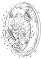
- FIG. 1 is a perspective view showing an example of a drum brake device according to an embodiment of the present invention.
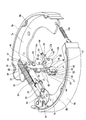
- FIG. 2 is a perspective view showing the drum brake device of FIG. 1 with a back plate, a wheel cylinder and an anchor omitted.
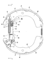
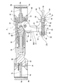
- FIG. 3 is a front view of the drum brake device of FIG. 4 is a cross-sectional view taken along the line AA in FIG.
- FIG. 5 is a front view showing a first example of a drum brake according to a conventional structure.
- 6 is a cross-sectional view taken along the line BB of FIG. 7 is a cross-sectional view taken along the line CC of FIG.
- FIG. 8 is a sectional view showing a second example of a drum brake according to a conventional structure.
- FIGS. 5 to 8 show an example of a drum brake device according to an embodiment of the present invention corresponding to the configurations (1) to (8) and (10) to (11).
- the structure of the drum brake device according to the present embodiment is applied to a parking brake device.
- the structure and operation other than the parking brake device are the same as those of the conventionally known leading / trailing drum brake device including the conventional structure shown in FIGS. 5 to 8 described above. Therefore, the illustration and description regarding the equivalent part are omitted or simplified, and the following description will focus on the characteristic part of the present embodiment.
- the structure of the service brake is constituted by a hydraulic mechanism, similar to the conventional structure described above. However, the structure of the drum brake device of this embodiment can also be applied to a service brake device.
- the parking brake device constituting the drum brake device of the present example is similar to the conventionally known drum brake type parking brake device described above, and includes a back plate 1, a pair of brake shoes 4a and 4b, and a drum 5 (see FIG. 8), an expansion / contraction device 16a, and a drive device 17a for driving the expansion / contraction device 16a.
- the expansion / contraction device 16a is a link-type power increase device including a pivot 24, a strut 25, and first and second expansion levers 26, 27. It is.
- the pivot 24 can swing around the pivot 24 in a state where a part of the first and second expansion levers 26 and 27 are overlapped with each other with respect to the axial direction of the pivot 24. It is to support the state.
- the strut 25 is configured by combining a holding cylinder 28, a screw rod 29, and a screw cylinder 30 as is widely known, for example, as described in Patent Document 7.
- the screw rod 29 is rotated by the lever 31 and the strut 25 is extended.
- the first engagement flat portion 32 is formed by performing press molding or the like on the base end portion (the right end portion in FIGS. 1 to 4) of the screw cylinder 30.
- the second engagement flat portion 33 is formed by performing press molding or the like on the distal end portion (the left end portion in FIGS. 1 to 4) of the holding cylinder 28.
- a notch 34 capable of engaging the web 7b of the other brake shoe 4b of the two brake shoes 4a and 4b so as to be able to press radially outward is provided at the tip of the second engagement flat portion 33. Is formed.
- the structure of the automatic gap adjusting device the structure of the conventional automatic gap adjusting device described in FIGS. 5 to 8 can be applied. Regardless of which structure is applied, the structure and operation of such an automatic gap adjustment device have been widely known from the past, as described in Patent Documents 6 to 8, and the like. Since it is not a characteristic part of, further detailed explanation is omitted.
- the first extension lever 26 is formed by bending a plate-shaped material or the like, and is provided with a pair of first plate portions 35, 35 provided in parallel and isolated from each other. It consists of the 1st connection part 36 which connects a part of both the 1st board parts 35 and 35. As shown in FIG.
- a pair of first through holes 37 penetrating these first plate portions 35, 35 in the thickness direction are concentric with each other at positions where they are aligned with each other in an intermediate portion between the first plate portions 35, 35. Is formed. Further, at the leading end portions (the upper end portions in FIGS. 1 to 2 and 4) of the first plate portions 35 and 35, a web 7a of one brake shoe 4a of the brake shoes 4a and 4b, and this A pair of first engaging portions 38, 38 that can be engaged in a state in which the web 7 a can be pressed radially outward is formed.
- an intermediate portion and a base end portion (lower end portions in FIGS. 1 to 2 and 4) of the first plate portions 35 and 35 are connected to each other of the first plate portions 35 and 35 through a step portion 39.
- the interval between the base end portions is continuous in a state where it is larger than the interval between the intermediate portions.
- a pair of first notches in the form of partial arcs opened on the one brake shoe 4a side are provided at the edge of the one brake shoe 4a side at the base end portions of the first plate portions 35, 35. 40 is formed.
- the distance between the mating portions 38 and 38 and the engagement portion of the one brake shoe 4a with the web 7a is the center of the first through-hole 37 and the first notches 40 (in the assembled state).
- the distance between the first notches 40 and the engaging portions of the first convex portions 60 of the bearing member 51 described later) is set to be sufficiently smaller than the so-called lever ratio of the first expansion lever 26. Is sufficiently large (greater than 1, for example, about 3 to 6).
- the first connecting portion 36 connects the intermediate portions of the end surfaces (left end surface in FIG. 4) of the first brake plate 4b side of the first plate portions 35, 35.
- the first connecting portion 36 is connected to the first connection portion 36 within a range in which the first and second expansion levers 26 and 27 do not interfere with each other. It can also be provided at the end edge (the right end edge in FIG. 4) on the one brake shoe 4a side of the first plate portions 35, 35.
- the second extension lever 27 is formed by bending a plate-like member or the like, and a pair of second plate portions 41 and 41 closely overlapped with each other except for a base end portion to be described later.
- the second plate portion 41 is composed of a second connecting portion 42 that connects parts of the 41.
- the second plate portions 41, 41 have a pair of (but continuous with each other) second through the second plate portions 41, 41 in the thickness direction at positions that are aligned with each other.
- a through hole 43 is formed.
- the first engaging portion of the screw cylinder 30 constituting the strut 25 is formed on the end surface of the distal end portion (the upper end portion in FIGS. 1 to 2 and 4) of the second plate portions 41 and 41 on the strut 25 side.
- a pair of (but continuous with each other) second engaging portions 44 that can be engaged with the flat portion 32 while being able to press the struts 25 radially outward is formed. Further, at the time of non-braking shown in FIG. 4, a part of the tip of both the second plate portions 41, 41 is engaged with a locking groove 45 formed in the web 7a of the one brake shoe 4a. ing. In this way, the displacement of the second extension lever 27 toward the one brake shoe 4a during non-braking is restricted.
- the engaging part which can engage with the web 7a of said one brake shoe 4a can also be provided in the front-end
- an intermediate portion and a base end portion (lower end portions in FIGS. 1 to 2 and 4) of the second plate portions 41 and 41 are connected to each other through the step portion 46.
- the interval between the base end portions is continuous in a state where it is larger than the interval between the intermediate portions.
- the second plate portions 41 and 41 are provided in such a manner that the intermediate portions are overlapped with each other from the front end portion, while the base end portions are parallel to each other and separated from each other. It is provided in the state.
- a pair of second arcs or U-shaped second ends opened on the other brake shoe 4b side at the edge of the other brake shoe 4b side at the base end of the second plate portions 41, 41.
- a notch 47 is formed.
- the center of the second through holes 43 (the center of the pivot 24 in the assembled state) and the second engaging portions 44 (the two engaging portions in the assembled state). 44 and the engagement portion of the screw cylinder 30 constituting the strut 25 with the first engagement flat portion 32) is set such that the center of the second through holes 43 and the second notches 47 ( In the assembled state, the distance between the second notches 47 and the engaging portions of the nuts 52, which will be described later) is sufficiently smaller than the second notches 47.
- the lever ratio of the expansion lever 27 is sufficiently large (greater than 1, for example, about 3 to 6). In the case of this example, the lever ratio of the first extension lever 26 and the lever ratio of the second extension lever 27 are substantially the same.
- the second connecting portion 42 connects the intermediate portions of the end surfaces (the right end surface in FIG. 4) on the one brake shoe 4a side of the second plate portions 41, 41.
- the second connecting portion 42 may be provided on an edge (the left end edge in FIG. 4) on the other brake shoe 4b side in the second plate portions 41, 41.
- Such first and second expansion levers 26 and 27 are disposed between the first plate portions 35 and 35 of the first expansion lever 26 and both second plate portions of the second expansion lever 27. 41 and 41 are combined.
- the first and second through holes 37 of the first plate portions 35 and 35 and the second through holes 43 of the second and second plate portions 41 and 41 are aligned with each other.
- the pivot shaft 24 is inserted into the second through holes 37 and 43, and the both expansion levers 26 and 27 are combined so as to be swingable and displaceable.
- both the inner surfaces of the first plate portions 35, 35 of the first extension lever 26 and both of the second extension levers 27 facing the both inner surfaces are provided.
- a slight gap is provided between the outer surfaces of the second plate portions 41 and 41. Therefore, in the combined state, when the first and second expansion levers 26 and 27 exhibit or release the braking force, the pivots 24 do not interfere with each other within a predetermined range. Oscillating displacement around the center is possible.
- the engagement portion between both the second engagement portions 44 of the second expansion lever 27 and the first engagement flat portion 32 of the screw cylinder 30 constituting the strut 25 is the first expansion lever. It is located in the part between 26 both the 1st board parts 35 and 35 mutually.
- the engagement portion X (see FIG. 4) between the first engagement portions 38, 38 of the first extension lever 26 and the web 7a of the one brake shoe 4a, and the second The engagement portion Y (see FIG. 4) between the second engagement portion 44 of the expansion lever 27 and the first engagement flat portion 32 of the screw cylinder 30 constituting the strut 25 is disposed in the strut 25.
- the position 24 of the pivot 24 with respect to the direction (shown in FIG. 4) is sandwiched between the opposite sides of each other and is displaced (installed in the opposite direction) by substantially the same distance.
- the first engagement portions 38, 38 of the first extension lever 26 and the engagement portion between the web 7a of the one brake shoe 4a and the second engagement portion of the second extension lever 27 are provided. 44 and the engaging part of the first engaging flat part 32 of the screw cylinder 30 constituting the strut 25 are arranged at substantially the same position as the position ⁇ of the pivot 24 in the arrangement direction of the strut 25. You can also.
- the base end portions of the first and second expansion levers 26 and 27 are rectangular through-holes 48 (FIG. 1) that are long in the length direction of the struts 25 formed in the back plate 1. 1), the back plate 1 protrudes from the back surface (the lower surface in FIG. 1) which is the surface opposite to the side where the brake shoes 4a and 4b are installed. Then, the first and second expansion levers 26 and 27 are disposed on the back surface portion of the back plate 1 so that the first and second expansion levers 26 and 27 are swung around the pivot 24. , 27 is provided with the driving device 17a for expanding and reducing the distance between the base end portions.
- the drive device 17 a includes a transmission mechanism 49 and an electric motor (not shown) corresponding to a drive source for driving the transmission mechanism 49.
- the transmission mechanism 49 includes a screw 50 corresponding to a male screw member that is rotationally driven by the output of the electric motor, a bearing member 51, and a nut 52 corresponding to a female screw member.
- the screw 50 includes a shaft portion 53 (see FIG. 4) and a large diameter portion 54 having a larger diameter than the shaft portion 53.
- the shaft portion 53 has a male screw portion 55 formed on the outer peripheral surface from the intermediate portion to the tip portion (left end portion in FIG. 4).
- the large-diameter portion 54 is provided at the base end portion (right end portion in FIG. 4) of the screw 50, and passes through one end (right end in FIG. 4) of the shaft portion 53 and the step portion 56. It is continuous.
- a hexagonal hole 57 opened in one axial direction is formed at the center of the large-diameter portion 54, and the distal end portion of the connecting member 58 capable of transmitting the output of the electric motor to the hexagonal hole 57. Is engaged.
- the connecting member 58 is capable of relative displacement in the axial direction with respect to the screw 50 and swinging displacement with respect to the screw 50, while being prevented from relative rotation with respect to the screw 50. (It can rotate in synchronization with the screw 50).
- the connecting member 58 by providing a reduction gear (not shown) between the connecting member 58 and the electric motor, the output (rotational force) of the electric motor is decelerated, and the increased torque causes the connecting member 58 to move. To be transmitted to the screw 50.
- the base end portion (the right end portion in FIG. 4) of the connecting member 58 is supported so as to be capable of axial displacement and swing displacement with respect to the output shaft of the speed reducer.
- the structure and installation method in such an electric motor and speed reducer are the same as the structure described in Patent Document 7 except that the connecting member 58 is provided, and thus illustration and detailed description thereof are omitted.
- the bearing member 51 is, for example, a sliding bearing, and is made of a material that is easy to slide, such as oil-impregnated metal or high-performance resin, and that has a high compressive strength.
- a bearing member 51 has a substantially rectangular parallelepiped bearing body 59 and a pair of first convex portions 60 corresponding to the first transmission portion.
- the bearing body 59 is formed with an insertion hole 61 (see FIG. 4) so as to penetrate from one side surface to the other side surface, and the inner peripheral surface of the insertion hole 61 is formed by the shaft portion 53 of the screw 50. It is possible to make sliding contact with a portion of the outer peripheral surface near the base end where the male screw portion 55 is not formed.
- Each of the first convex portions 60 has a cylindrical shape, and a pair of side surfaces located on opposite sides of the side surface of the bearing main body 59 (side surfaces other than the side surface on which the insertion hole 61 is formed). These are provided concentrically with each other in a state protruding from both side surfaces.
- the shaft portion 53 of the screw 50 is inserted into the insertion hole 61, and one end surface (the right end surface in FIG. 4) of the bearing body 59 and the stepped portion 56 of the screw 50 are connected. Assembled in a contact state.
- the nut 52 includes a substantially rectangular parallelepiped nut main body 62 and a pair of second convex portions 65 and 65 corresponding to a second transmission portion.
- the nut body 62 is formed with a screw hole 64 that penetrates from one side surface to the other side surface and has an internal thread portion 63 that can be screwed with the external thread portion 55 of the screw 50 on its inner peripheral surface.
- Each of the second convex portions 65 and 65 has a cylindrical shape, and a pair of side surfaces located on opposite sides of the side surface of the nut body 62 (other than the side surface on which the screw hole 64 is formed). These are provided concentrically with each other in a state protruding from both side surfaces.
- Such a nut 52 is assembled to the distal end portion of the screw 50 in a state where the female screw portion 63 and the male screw portion 55 of the screw 50 are screwed together.
- both first protrusions 60 of the bearing member 51 are engaged with both first notches 40 of the first expansion lever 26.
- the first expansion lever 26 and the bearing member 51 can be oscillated and displaced with the first convex portion 60 as the center.
- the displacement of the screw 50 in the other axial direction (the left direction in FIG. 4) is caused by the first projecting portion 60 of the screw 50 and the first convex portions 60 of the bearing member 51. It is transmitted to the expansion lever 26.
- the screw 50 is displaced in one axial direction (rightward in FIG. 4)
- the bearing member 51 is moved together with the base end of the first expansion lever 26 by the elasticity of the return springs 10a and 10b.
- the second protrusions 65, 65 of the nut 52 are engaged with the second notches 47, 47 of the second expansion lever 27, so that the nut 52 is prevented from rotating. Yes. Further, in the assembled state, the second extension lever 27 and the nut 52 can be oscillated and displaced around the second convex portions 65 and 65 with respect to each other. Further, the displacement of the nut 52 in one axial direction (the right side in FIG. 4) based on the rotational movement of the screw 50 is caused by the second projecting portions 65 and 65 of the nut 52 through the second projecting portions 65 and 65. It is transmitted to the expansion lever 27. When the nut 52 is displaced in the other axial direction (left side in FIG.
- the base end portion of the second extension lever 27 is moved in the other axial direction by the elastic biasing force of the return springs 10a and 10b. Displace. In this manner, the engagement state between the second protrusions 65 and 65 of the nut 52 and the second notches 47 and 47 of the second expansion lever 27 is maintained.
- Such a transmission mechanism 49 is an ordinary feed screw mechanism having irreversibility (self-locking function). For this reason, even when energization of the electric motor is stopped, it is possible to maintain a state where the braking force is exerted without energizing any part.
- the transmission mechanism 49 may be reversible such as a ball nut type feed screw mechanism.
- a lock structure for securing the braking force even after the energization of the electric motor is stopped is separately provided in, for example, the speed reducer.
- the parking brake constituting the drum brake device of the present example constructed as described above exerts braking force by acting as follows.
- the output of the electric motor is transmitted to the screw 50 via the speed reducer and the connecting member 58, and the screw 50 is rotated in a predetermined direction.
- the screw 50 is displaced in the other axial direction (left side in FIG. 4) based on the threaded engagement between the male screw portion 55 of the screw 50 and the female screw portion 63 of the nut 52.
- the displacement of the screw 50 in the other axial direction is transmitted to the bearing member 51 via the stepped portion 56 of the screw 50, and further, the first first via the first convex portions 60 of the bearing member 51. Is transmitted to the expansion lever 26.
- the first extension lever 26 swings clockwise about the pivot 24.
- the nut 52 is displaced in one axial direction (the right side in FIG. 4) based on the threaded engagement with the male threaded portion 55 of the screw 50.
- the displacement of the nut 52 in one axial direction is transmitted to the second expansion lever 27 via both second convex portions 65 and 65 of the nut 52.
- the second extension lever 27 swings counterclockwise about the pivot 24.
- the tip of the first extension lever 26 is directly on the web 7a of the one brake shoe 4a, and the tip of the second extension lever 27 is on the other brake shoe 4b.
- Such an expansion / contraction device 16a which is a link-type power increasing device composed of the first and second expansion levers 26, 27 and the pivot shaft 24, has a small friction loss and an excellent transmission efficiency.
- the gear-type speed reducer used in the structure of the present example inevitably causes a certain amount of friction loss, but the speed reduction by the amount increased by the first and second expansion levers 26 and 27.
- the increase ratio in the speed reduction part can be kept small, and the friction loss in the reduction part can be kept low accordingly.
- the drum brake device of this example it is not necessary to particularly increase the rigidity and strength of the portion supporting the drive device 17a in the back plate 1, the substrate, etc., and it is easy to reduce the weight of the drum brake device. That is, in the case of the parking brake device that constitutes the drum brake device of the present example, the front end portions of the first and second expansion levers 26 and 27 are brought closer to each other with the braking performed as described above. Reaction force is added. This reaction force is applied to the pivot 24 as forces opposite to each other. Further, the reaction force applied to the distal end portion of the first expansion lever 26 is transmitted from the base end portion of the first expansion lever 26 through the drive device 17a (both first convex portions 60 of the bearing member 51).
- the screw 50 is applied as a force in one axial direction (right direction in FIG. 4).
- the reaction force applied to the distal end portion of the second expansion lever 27 causes the drive device 17a (the two convex portions 65, 65 of the nut 52 to move from the base end portion of the second expansion lever 27).
- the screw 50 constituting the transmission mechanism 49 and the connecting member 58 engaged with the base end portion of the screw 50 are engaged with each other so as to be able to swing. Further, the first expansion lever 26 and the bearing member 51 are engaged with each other so as to be swingable. Further, the second extension lever 27 and the nut 52 are engaged with each other so as to be swingable. Therefore, each member (screw 50, bearing member 51, nut 52) constituting the transmission mechanism 49 with respect to the swing of the first and second expansion levers 26, 27 around the pivot 24 is provided. It can follow by swinging displacement. As a result, the rotational force from the electric motor can be smoothly transmitted to the screw 50 via the connecting member 58.
- the position of the pivot 24, which is the swing center of the first and second expansion levers 26, 27, is biased toward the respective distal ends on the output side. For this reason, even when the force applied to the base end portions of the first and second expansion levers 26 and 27 is small, the distance between the distal ends of the first and second expansion levers 26 and 27 is increased by a large force. . As a result, an electric motor having a relatively small output can be used to swing and displace the first and second expansion levers 26 and 27, and the size and weight can be reduced.
- the second expansion lever 27 is disposed between the first plate portions 35 and 35 of the first expansion lever 26 so that the first and second expansion levers 26 and 27 are disposed. Are disposed so as to overlap each other with respect to the axial direction of the pivot 24. For this reason, the dimensions of the first and second expansion levers 26 and 27 occupying in the arrangement direction of the strut 25 can be kept small, and the drum brake device can be further reduced in size and weight. . Further, when the first and second expansion levers 26 and 27 swing, the first and second expansion levers 26 and 27 do not interfere with each other with respect to the arrangement direction of the strut 25.
- the first and second expansion levers 26 and 27 occupying the arrangement direction.
- the size of can be kept small. As a result, it is possible to reduce the size and weight of the drum brake device and to ensure the rigidity of the tip portions of the first and second expansion levers 26 and 27.
- first engagement portions 38 are formed at the distal end portions of the first plate portions 35 35 of the first extension lever 26.
- the first engaging portions 38, 38 and the web 7a of the one brake shoe 4a are engaged at two positions.
- the engaging part of the 2nd engaging part 44 of the said 2nd expansion lever 27 and the said strut 25 exists in the part between these two locations. For this reason, at the time of braking, there is no moment in the direction in which the two expansion levers 26 and 27 are inclined, and the postures of the two expansion levers 26 and 27 are stabilized. A stable pressing force can be applied to the webs 7a and 7b.
- the engaging portion between the first engaging flat portion 32 of the screw cylinder 30 constituting the strut 25 and both the second engaging portions 44 of the second extension lever 27 is the first extension lever. 26 is arranged in a portion between both first plate portions 35, 35. For this reason, it is possible to position the strut 25 and the second expansion lever 27 with respect to the arrangement direction of the strut 25 and the axial direction of the pivot 24. Furthermore, the dimension in the arrangement direction of the struts 25 can be kept small, and the drum brake device can be further reduced in size and weight.
- first engaging portions 38, 38 of the first extension lever 26 and the web 7a of the one brake shoe 4a, and the second engaging portion of the second extension lever 27 are provided. 44 and the engagement portion between the first engagement flat portion 32 of the screw cylinder 30 constituting the strut 25 are substantially the same distance on the opposite sides with respect to the arrangement direction of the strut 25 with the pivot 24 interposed therebetween. It is just shifted. For this reason, the change in the lever ratio before and after the first and second expansion levers 26 and 27 exert the braking force is reduced, and a stable braking force can be exhibited.
- the first engagement portions 38, 38 of the first extension lever 26 and the engagement portion between the web 7a of the one brake shoe 4a and the second engagement portion of the second extension lever 27 are provided.
- the distal end portion of the second extension lever 27 is in a state where the second extension lever 27 is prevented from being displaced toward the one brake shoe 4a when not braked.
- the web 7a is engaged. Therefore, the positioning of the second expansion lever 27 in the non-braking position with respect to the arrangement direction of the struts 25 is performed by engaging the distal end portion of the second expansion lever 27 and the proximal end portion of the strut 25, and This is achieved by the engagement between the tip of the second extension lever 27 and the web 7a of the one brake shoe 4a.
- a back plate 1 supported and fixed to the structural members of the suspension device;
- a pair of brake shoes 4a, 4b supported so as to be capable of displacement in the radial direction of the back plate 1 at two positions opposite to the radial direction of the back plate 1;
- a drum 5 provided so as to cover both the brake shoes 4a and 4b and rotating together with the wheels;
- An expansion / contraction device 16a provided between the inner peripheral edges of the webs 7a, 7b constituting the brake shoes 4a, 4b, in order to expand / contract the distance between the brake shoes 4a, 4b;
- a drum brake device comprising:
- the expansion / contraction device 16a includes a pivot 24, a strut 25, and first and second expansion levers 26 and 27, The pivot 24 supports the first and second expansion levers 26 and 27 so as to be swingable around the pivot 24.
- the first expansion lever 26 has a first through hole 37 for inserting the pivot shaft 24, and a tip portion thereof is a web 7a of one brake shoe 4a of the two brake shoes 4a and 4b. And one of the struts 25 is engaged with the one member so as to be able to press radially outward.
- the second expansion lever 27 is disposed so that a part thereof overlaps a part of the first expansion lever 26 with respect to the axial direction of the pivot 24, and a second extension lever 27 is inserted through the pivot 24.
- Two through-holes 43 the front end of which is engaged with the other member of the web 7a of the one brake shoe 4a and the strut 25 so that the other member can be pressed radially outward.
- the drive device 17a includes a transmission mechanism 49 and a drive source (electric motor) for driving the transmission mechanism 49.
- the transmission mechanism 49 engages with the first expansion lever 26 to cause the first expansion lever 26 to swing around the pivot 24 (first convex portion) 60.
- a second transmission portion that engages with the second expansion lever 27 and that causes the second expansion lever 27 to swing in the opposite direction to the first expansion lever 26 about the pivot 24.
- 2nd convex part) 65,65 The drum brake device provided with.
- the first extension lever 26 includes a pair of plate portions (first plate portions) 35 and 35 provided in a state of being separated from each other in parallel, and both plate portions (first plate portions) 35 and 35.
- a pair of the first through holes 37 are formed at positions where the both plate portions (first plate portions) 35, 35 of the first expansion lever 26 are aligned with each other, and the both plate portions (first plate) Part) 35, 35 is provided with a pair of first engaging portions 38, 38 that can be engaged with the one member
- the second expansion lever 27 has the second through-hole 43 formed therein, and a second engagement portion 44 that can be engaged with the other member is provided at a tip portion, and the first expansion lever 27 It is arrange
- An engagement portion between the other member and the second engagement portion 44 of the second expansion lever 27 is a plate portion (first plate portion) 35 of the first expansion lever 26, The drum brake device described in [ii] above, which is disposed in a portion between the 35.
- the first transmission portion (first convex portion) 60 can be displaced in the axial direction of the male screw member (screw) 50 in conjunction with the male screw member (screw) 50 or the male screw member (screw) 50.
- the second transmission portions (second convex portions) 65, 65 can be displaced in the axial direction of the male screw member (screw) 50 in conjunction with the female screw member (nut) 52 or the female screw member (nut) 52. It is provided in the member, The first extension lever 26 and the first transmission part (first convex part) 60 are engaged, In any one of the above [i] to [iii], the second extension lever 27 and the second transmission portions (second convex portions) 65 and 65 are engaged with each other.
- a connecting member 58 capable of transmitting a rotational force of the drive source (electric motor) to the male screw member (screw) 50 is provided at a base end portion of the male screw member (screw) 50.
- the drum brake device according to any one of [i] to [iii], which is smaller than a distance to the engaging portion with the second transmission portion (second convex portion) 65, 65.
- the base ends of the first and second expansion levers 26 and 27 pass through the through holes 48 formed in the back plate 1 and the brake shoes 4a and 4b on both sides of the back plate 1 Is protruded from the back side, which is the opposite side to the side where An electric motor, which is a drive source, is installed in a portion that covers the through hole 48 on the back surface of the back plate 1.
- the base end portion of the first expansion lever 26 and the first transmission portion (first convex portion) 60 are engaged, Any one of the above [i] to [iii] in which the base end portion of the second expansion lever 27 and the second transmission portions (second convex portions) 65 and 65 are engaged.
- the drum brake device described in one.
- An engagement portion between the first expansion lever 26 and the one member; An engagement portion between the second expansion lever 27 and the other member is: The drum brake according to any one of the above [i] to [iii], which is disposed on opposite sides with respect to the arrangement direction of the struts 25 with the pivot shaft 24 interposed therebetween in a non-braking state.
- apparatus [Ix] An engagement portion between the first expansion lever 26 and the one member; An engagement portion between the second expansion lever 27 and the other member is: The drum according to any one of the above [i] to [iii], which is disposed at substantially the same position as the position of the pivot 24 in the disposing direction of the strut 25 in a non-braking state. Brake device.
- the structure of the drum brake device of the present invention can be applied not only to a parking brake but also to a service brake.
- the structure of the 1st and 2nd expansion lever which comprises the expansion / contraction apparatus of this invention is not limited to the structure of one example of embodiment mentioned above.
- the first expansion lever and the second expansion lever are each constituted by a single plate-like member, and the first and second expansion levers can swing around the pivot axis, and It can also be set as the structure supported in the state overlapped regarding the axial direction of this pivot.
- the distal end of the first expansion lever is engaged with the base end of the strut so that the strut can be pressed radially outward
- the distal end of the second expansion lever is engaged with the web of one brake shoe. It is also possible to engage the web so that it can be pressed radially outward.
Landscapes
- Engineering & Computer Science (AREA)
- General Engineering & Computer Science (AREA)
- Mechanical Engineering (AREA)
- Braking Arrangements (AREA)
Abstract
第一の拡張レバー33と第二の拡張レバー34とが、枢軸31を中心に揺動変位可能に支持される。第一の拡張レバー33の先端部がブレーキシュー4aのウェブ7aに、ウェブ7aを径方向外方に押圧可能な状態で係合される。第二の拡張レバー34の先端部がストラット32の基端部に、ストラット32を径方向外方に押圧可能な状態で係合される。駆動装置27aを構成する伝達機構56により、第一の拡張レバー33と、第二の拡張レバー34とが互いに逆方向に揺動変位させられる。
Description
この発明は、車両(自動車)を停止状態に保つ為のドラムブレーキ装置の改良に関する。
車両の制動を行う為に、ドラムブレーキ装置が広く使用されている。ドラムブレーキ装置には、各種型式のものが知られている。このうちで、リーディング・トレーリング式のドラムブレーキ装置が、前進時にも後退時にも安定した制動力を得られる事から、広く使用されている。
図5~7は、特許文献1に記載された、リーディング・トレーリング式の従来構造に係るドラムブレーキ(ドラムブレーキ装置)の第1例を示している。このドラムブレーキは、バックプレート1と、アンカ2と、ホイールシリンダ3と、一対のブレーキシュー4a、4bと、ドラム5とを備える。
図5~7は、特許文献1に記載された、リーディング・トレーリング式の従来構造に係るドラムブレーキ(ドラムブレーキ装置)の第1例を示している。このドラムブレーキは、バックプレート1と、アンカ2と、ホイールシリンダ3と、一対のブレーキシュー4a、4bと、ドラム5とを備える。
前記バックプレート1は、ナックル、アクスルハウジング等の懸架装置の構成部材に支持固定される。又、前記アンカ2は、前記バックプレート1の円周方向1箇所の径方向外寄り部分に支持固定されている。又、前記ホイールシリンダ3は、前記バックプレート1の外径寄り部分におけるこのバックプレート1の径方向に関して、前記アンカ2と反対側の位置に固定されている。前記ホイールシリンダ3は、シリンダ筒6の両端部に一対のピストンを油密に内嵌したものであり、このシリンダ筒6の中央部内側に油圧を導入する事により、このシリンダ筒6の両端部からの前記両ピストンの突出量を増大させる(これら両ピストン同士の間隔を拡げる)様に構成されている。又、前記両ブレーキシュー4a、4bは、前記バックプレート1の径方向反対側の2箇所位置における前記アンカ2と前記ホイールシリンダ3との間部分に、このバックプレート1の径方向に関する変位を可能に支持されている。
前記両ブレーキシュー4a、4bはそれぞれ、大略円弧形のウェブ7a、7bと、このウェブ7a、7bの外周縁部にそれぞれの幅方向中央部を溶接等により固定した裏板8a、8bと、この裏板8a、8bの外周面に添着固定したライニング9a、9bとから成る。そして、それぞれのウェブ7a、7bの周方向一端縁が前記アンカ2に突き当てられると共に、周方向他端縁が前記両ピストンの先端部に形成した係合溝の底面に突き当てられている。更に、前記ドラム5は、鋳鉄等によりシャーレ状に形成されており、前記両ブレーキシュー4a、4bを覆う状態で設けられて車輪と共に回転する。
上述の様に構成するドラムブレーキにより制動を行う際には、ブレーキペダルの踏み込みによって前記ホイールシリンダ3内に油圧を導入し、前記シリンダ筒6からの前記両ピストンの突出量を増大させる。すると、これら両ピストンの先端部にそれぞれの周方向他端縁を突き当てた前記両ウェブ7a、7b同士の間隔が拡がり、前記両ブレーキシュー4a、4bが、前記アンカ2を中心として径方向外方に揺動変位する。この結果、これら両ブレーキシュー4a、4bのライニング9a、9bの外周面が前記ドラム5の内周面に押し付けられて、制動が行われる。制動解除に伴って前記ホイールシリンダ3内の油圧を除くと、前記両ブレーキシュー4a、4bが、リターンスプリング10a、10bの弾性付勢力により、前記両ピストンを前記シリンダ筒6内に押し込みつつ、径方向内方に変位する。
尚、図5~7に示した従来構造に係るドラムブレーキの第1例の場合、自動間隙調整用のストラット11を設けて、前記ライニング9a、9bの摩耗に拘らず、非制動状態におけるこれら両ライニング9a、9bの外周面と前記ドラム5の内周面との間の隙間(間隙)を適正値に保てる様にしている。前記ストラット11は、主板部12と副板部13とを枢軸14により連結して構成される。又、この枢軸14は、前記副板部13に固定されると共に、前記主板部12に形成した長孔15に、この長孔15の長さ方向の変位を可能に係合している。制動に伴って前記両ウェブ7a、7b同士の間隔が拡がると、前記副板部13が前記枢軸14を中心として、図6の時計回り方向に揺動する。
前記副板部13の端縁のうちで前記主板部12の端縁と突き当たる部分は、この揺動方向に関して後方(図6中の下方)に向かう程前記枢軸14の中心からの距離が長くなっている。この為、この枢軸14を中心とする前記副板部13の揺動変位に伴って、この副板部13の端縁と前記主板部12の端縁とが係合する(突き当たる)。そして、制動解除に伴って前記両ウェブ7a、7b同士の間隔が、前記両リターンスプリング10a、10bの弾性付勢力に基づいて収縮した場合でも、その収縮量は、制動の為の拡張量に比べて、前記副板部13の揺動変位に見合う分だけ縮まる。この為、前記両ライニング9a、9bの摩耗に拘らず、これら両ライニング9a、9bの外周面と前記ドラム5の内周面との間の隙間の大きさが、適正値に保たれる。
走行中の車両を減速若しくは停止させる所謂サービスブレーキの使用時の作用、並びに、自動間隙調整装置の作用は上述の通りであるが、ブレーキペダルを踏み込まずに車両を停止状態に維持する駐車ブレーキ装置が、上述の様なドラムブレーキに組み込まれる事も、広く行われている。又、サービスブレーキが油圧式により行われ、駐車ブレーキが電動モータを駆動源とするリンク機構により機械的に行われる事も、特許文献2~3、7に記載される等により従来から知られており、一部の車両で実施されている。更に、油圧機構を省略し、電動モータを駆動源とする機械式の増力装置のみで、サービスブレーキと駐車ブレーキとの両方の機能を発揮させる電動式のブレーキ装置も、特許文献4~6等に記載されて、従来から知られている。
図8は、特許文献7に記載された、サービスブレーキが油圧式により行われ、駐車ブレーキが電動モータを駆動源とするリンク機構により機械的に行われる従来構造に係るドラムブレーキの第2例を示している。ドラムブレーキの基本的構造に関しては、前述の図5に記載した一般的な構造と同様であるから重複する説明を省略若しくは簡略にし、以下、駐車ブレーキ装置部分の構成及び作用を中心に説明する。
一対のブレーキシュー4a、4b同士の間隔を拡縮する為の拡縮装置16が、これら両ブレーキシュー4a、4bを構成するウェブ7a、7bの内周縁同士の間に設けられ、駆動装置17により前記拡縮装置16を伸縮させる(駆動する)様に構成している。
この拡縮装置16は、ストラット11bと、第一及び第二の拡張レバー18、19と、これら第一及び第二の拡張レバー18、19の中間部同士を連結する結合リンク20とを備えているリンク式の増力装置である。
この拡縮装置16は、ストラット11bと、第一及び第二の拡張レバー18、19と、これら第一及び第二の拡張レバー18、19の中間部同士を連結する結合リンク20とを備えているリンク式の増力装置である。
この様な構造の駐車ブレーキ装置により制動力を発生させる場合、前記第一及び第二の拡張レバー18、19の基端部が、前記駆動装置17を構成する第一及び第二の押圧部材21、22により、互いに反対側から押圧される。すると、前記第一の拡張レバー18が、前記結合リンク20の一端部(図8中の右側)との枢支部23aを中心として揺動変位する一方で、前記第二の拡張レバー19が、前記結合リンク20の他端部(図8中の左側)との枢支部23bを中心として前記第一の拡張レバー18と逆方向に揺動変位する。すると、前記第一の拡張レバー18の先端部が一方のブレーキシュー4aを径方向外方に押圧すると共に、前記第二の拡張レバー19の先端部が、前記ストラット11bを介して他方のブレーキシュー4bを径方向外方に押圧する。その結果、前記両ブレーキシュー4a、4bのライニング9a、9bがドラム5の内周面に押し付けられて、制動が行われる。
この様な構造の場合、前記第一の拡張レバー18、前記第二の拡張レバー19、及び前記結合リンク20で構成するリンク式の増力装置(前記拡縮装置16)は、伝達ロスが少ない為、比較的出力の小さい電動モータを使用して小型・軽量化を図る事ができる。又、制動に伴う反力を前記増力装置内(前記結合リンク20部分)で相殺して、前記駆動装置17を支持固定している前記バックプレート1にこの制動に伴う大きな反力が加わる事を防止できる。但し、前記第一及び第二の拡張レバー18、19が、前記ストラット11bの配設方向(図8中の左右方向)に隣り合う状態で配置されている。この為、リンク式の増力装置である拡縮装置16には、このストラット11bの配設方向に占める前記第一及び第二の拡張レバー18、19の寸法を小さくする観点、或は、前記第一及び第二の拡張レバー18、19の基端部の揺動量を大きく確保する観点から改良の余地がある。
本発明は、上述の様な事情に鑑み、伝達ロスが少ないリンク式の増力装置を採用する事により、比較的出力の小さな駆動源(電動モータ等)を使用でき、しかも、制動に伴う反力が前記増力装置、或は駆動装置を支持しているバックプレート等の部材に加わる事がない構造で、より一層の小型・軽量化を図るべく、前記増力装置におけるストラットの配設方向に関する寸法を小さくできるドラムブレーキ装置を提供することを目的とする。
本発明の上記目的は、下記構成のドラムブレーキ装置により達成される。
(1) ドラムブレーキ装置は、バックプレートと、一対のブレーキシューと、ドラムと、拡縮装置と、前記拡縮装置を駆動する為の駆動装置とを備える。
前記バックプレートは、ナックル、アクスルハウジング等の懸架装置の構成部材に支持固定される。
又、前記両ブレーキシューは、前記バックプレートの径方向反対側の2箇所位置に、前記バックプレートの径方向に関する変位が可能に支持されている。
又、前記ドラムは、前記両ブレーキシューを覆う状態で設けられて、車輪と共に回転する。
又、前記拡縮装置は、前記両ブレーキシュー同士の間隔を拡縮する為、これら両ブレーキシューを構成するウェブの内周縁同士の間に設けられている。
(1) ドラムブレーキ装置は、バックプレートと、一対のブレーキシューと、ドラムと、拡縮装置と、前記拡縮装置を駆動する為の駆動装置とを備える。
前記バックプレートは、ナックル、アクスルハウジング等の懸架装置の構成部材に支持固定される。
又、前記両ブレーキシューは、前記バックプレートの径方向反対側の2箇所位置に、前記バックプレートの径方向に関する変位が可能に支持されている。
又、前記ドラムは、前記両ブレーキシューを覆う状態で設けられて、車輪と共に回転する。
又、前記拡縮装置は、前記両ブレーキシュー同士の間隔を拡縮する為、これら両ブレーキシューを構成するウェブの内周縁同士の間に設けられている。
更に、上記ドラムブレーキ装置における前記拡縮装置は、枢軸と、ストラットと、第一及び第二の拡張レバーとを備える。
前記枢軸は、これら第一及び第二の拡張レバーを、前記枢軸を中心とした揺動が可能な状態に支持するものである。
又、前記第一の拡張レバーは、前記枢軸を挿通する為の第一の通孔を有し、その先端部が、前記両ブレーキシューのうちの一方のブレーキシューのウェブと前記ストラットとのうちの一方の部材に、この一方の部材を径方向外方に押圧可能に係合させられている。
又、前記第二の拡張レバーは、前記枢軸を挿通する為の第二の通孔を有し、その先端部が、前記一方のブレーキシューのウェブと前記ストラットとのうちの他方の部材に、この他方の部材を径方向外方に押圧可能に係合させられている。
この為に、前記第一の拡張レバーの一部と、前記第二の拡張レバーの一部とが、前記枢軸の軸方向に関して重畳した状態で配置されている。
又、前記ストラットの先端部は、前記両ブレーキシューのうちの他方のブレーキシューのウェブに、このウェブを径方向外方に押圧可能に係合させられている。
前記枢軸は、これら第一及び第二の拡張レバーを、前記枢軸を中心とした揺動が可能な状態に支持するものである。
又、前記第一の拡張レバーは、前記枢軸を挿通する為の第一の通孔を有し、その先端部が、前記両ブレーキシューのうちの一方のブレーキシューのウェブと前記ストラットとのうちの一方の部材に、この一方の部材を径方向外方に押圧可能に係合させられている。
又、前記第二の拡張レバーは、前記枢軸を挿通する為の第二の通孔を有し、その先端部が、前記一方のブレーキシューのウェブと前記ストラットとのうちの他方の部材に、この他方の部材を径方向外方に押圧可能に係合させられている。
この為に、前記第一の拡張レバーの一部と、前記第二の拡張レバーの一部とが、前記枢軸の軸方向に関して重畳した状態で配置されている。
又、前記ストラットの先端部は、前記両ブレーキシューのうちの他方のブレーキシューのウェブに、このウェブを径方向外方に押圧可能に係合させられている。
又、前記駆動装置は、伝達機構と、この伝達機構を駆動する為の駆動源とを備える。
前記伝達機構は、前記第一の拡張レバーと係合して、前記第一の拡張レバーが前記枢軸を中心として揺動させられる第一の伝達部を有する。更に、前記第二の拡張レバーと係合して、前記第二の拡張レバーが前記枢軸を中心として前記第一の拡張レバーと逆方向に揺動させられる第二の伝達部を有する。
前記伝達機構は、前記第一の拡張レバーと係合して、前記第一の拡張レバーが前記枢軸を中心として揺動させられる第一の伝達部を有する。更に、前記第二の拡張レバーと係合して、前記第二の拡張レバーが前記枢軸を中心として前記第一の拡張レバーと逆方向に揺動させられる第二の伝達部を有する。
(2) 上記(1)の構成のドラムブレーキ装置であって、前記第一の拡張レバーは、互いに平行に離隔した状態で設けられた一対の板部と、これら両板部を連結する連結部とにより構成される。
又、前記第一の拡張レバーの両板部の互いに整合する位置に、一対の前記第一の通孔が形成される。又、これら両板部の先端部に、前記一方の部材と係合可能な一対の第一の係合部が設けられる。
一方、前記第二の拡張レバーに前記第二の通孔が形成される。又、前記第二の拡張レバーの先端部に、前記他方の部材と係合可能な第二の係合部が設けられる。更に、前記第二の拡張レバーが、前記第一の拡張レバーの両板部同士の間部分に配置される。そして、前記枢軸が、前記両第一の通孔と、前記第二の通孔とに挿通される。
又、前記第一の拡張レバーの両板部の互いに整合する位置に、一対の前記第一の通孔が形成される。又、これら両板部の先端部に、前記一方の部材と係合可能な一対の第一の係合部が設けられる。
一方、前記第二の拡張レバーに前記第二の通孔が形成される。又、前記第二の拡張レバーの先端部に、前記他方の部材と係合可能な第二の係合部が設けられる。更に、前記第二の拡張レバーが、前記第一の拡張レバーの両板部同士の間部分に配置される。そして、前記枢軸が、前記両第一の通孔と、前記第二の通孔とに挿通される。
(3) 上記(2)の構成のドラムブレーキ装置であって、前記他方の部材と、前記第二の拡張レバーの第二の係合部との係合部が、前記第一の拡張レバーの両板部同士の間部分に配置される。
(4) 上記(1)~(3)の何れかの構成のドラムブレーキ装置であって、前記伝達機構が、その一部に雄ねじ部を有する雄ねじ部材と、前記雄ねじ部と螺合する雌ねじ部を有する雌ねじ部材とを備えた送りねじ機構とされる。
又、前記第一の伝達部が、前記雄ねじ部材又は前記雄ねじ部材と連動して前記雄ねじ部材の軸方向に変位可能な部材に設けられる。
又、前記第二の伝達部が、前記雌ねじ部材又は前記雌ねじ部材と連動して前記雄ねじ部材の軸方向に変位可能な部材に設けられる。
そして、前記第一の拡張レバーと、前記第一の伝達部とが係合させられる。
更に、前記第二の拡張レバーと、前記第二の伝達部とが係合させられる。
又、前記第一の伝達部が、前記雄ねじ部材又は前記雄ねじ部材と連動して前記雄ねじ部材の軸方向に変位可能な部材に設けられる。
又、前記第二の伝達部が、前記雌ねじ部材又は前記雌ねじ部材と連動して前記雄ねじ部材の軸方向に変位可能な部材に設けられる。
そして、前記第一の拡張レバーと、前記第一の伝達部とが係合させられる。
更に、前記第二の拡張レバーと、前記第二の伝達部とが係合させられる。
(5) 上記(4)の構成のドラムブレーキ装置であって、前記雄ねじ部材の基端部に、前記駆動源の回転力を前記雄ねじ部材に伝達可能な連結部材が、前記雄ねじ部材に対して揺動可能に係合される。
又、前記第一の拡張レバーと、前記送りねじ機構の第一の伝達部とが互いに揺動可能な状態に係合される。
更に、前記第二の拡張レバーと、この送りねじ機構の第二の伝達部とが互いに揺動可能な状態に係合される。
又、前記第一の拡張レバーと、前記送りねじ機構の第一の伝達部とが互いに揺動可能な状態に係合される。
更に、前記第二の拡張レバーと、この送りねじ機構の第二の伝達部とが互いに揺動可能な状態に係合される。
(6) 上記(1)~(5)の何れかの構成のドラムブレーキ装置であって、前記第一の通孔の中心から、前記第一の拡張レバーの先端部と前記一方の部材との係合部までの距離が、この中心から、前記第一の拡張レバーと前記第一の伝達部との係合部までの距離よりも小さくされる。
又、前記第二の通孔の中心から、前記第二の拡張レバーの先端部と前記他方の部材との係合部までの距離が、この中心から、前記第二の拡張レバーと前記第二の伝達部との係合部までの距離よりも小さくされる。
又、前記第二の通孔の中心から、前記第二の拡張レバーの先端部と前記他方の部材との係合部までの距離が、この中心から、前記第二の拡張レバーと前記第二の伝達部との係合部までの距離よりも小さくされる。
(7) 上記(1)~(6)の何れかの構成のドラムブレーキ装置であって、前記第一及び第二の拡張レバーの基端部が、前記バックプレートに形成した通孔を通じて、前記バックプレートの両側面のうちで前記両ブレーキシューを設置した側と反対側の面である裏面から突出させられる。
又、前記バックプレートの裏面で前記通孔を覆う部分に、駆動源である電動モータが設置される。
又、前記第一の拡張レバーの基端部と、前記第一の伝達部とが係合させられる。
更に、前記第二の拡張レバーの基端部と、前記第二の伝達部とが係合させられる。
又、前記バックプレートの裏面で前記通孔を覆う部分に、駆動源である電動モータが設置される。
又、前記第一の拡張レバーの基端部と、前記第一の伝達部とが係合させられる。
更に、前記第二の拡張レバーの基端部と、前記第二の伝達部とが係合させられる。
(8) 上記(1)~(7)の何れかの構成のドラムブレーキ装置であって、前記第一の拡張レバーと前記一方の部材との係合部と、前記第二の拡張レバーと前記他方の部材との係合部とが、非制動時の状態で、前記枢軸を挟み、前記ストラットの配設方向に関して互いに反対側に配置される。
(9) 上記(1)~(7)の何れかの構成のドラムブレーキ装置であって、前記第一の拡張レバーと前記一方の部材との係合部と、前記第二の拡張レバーと前記他方の部材との係合部とが、非制動時の状態で、前記ストラットの配設方向に関する前記枢軸の位置と、ほぼ同位置(例えば、制動に伴う変位方向に関して、1mmの範囲内)に配置される。
(10) 上記(1)~(9)の何れかの構成のドラムブレーキ装置であって、前記第二の拡張レバーの先端部が、非制動時に前記一方の部材側への変位を規制された状態で、前記一方の部材と係合させられる。
(11) 上記(1)~(10)の何れかの構成のドラムブレーキ装置であって、前記伝達機構が不可逆性を有する。
上記(1)の様に構成したドラムブレーキ装置は、次の様に作用して、制動力を発揮する。制動時には、駆動装置により拡縮装置を構成する第一及び第二の拡張レバーが、枢軸を中心として互いに反対方向に揺動変位して、これら第一及び第二の拡張レバーの先端部同士の間隔を拡げる。そして、前記第一の拡張レバーの先端部が一方のブレーキシューのウェブとストラットとのうちの一方の部材を直接又は他の部材を介して、前記第二の拡張レバーの先端部が前記一方のブレーキシューのウェブと前記ストラットとのうちの他方の部材を直接又は他の部材を介して、径方向外方に押圧する。その結果、前記両ブレーキシューが径方向外方に変位して、これら両ブレーキシューのライニングをドラムの内周面に押し付けて、制動を行わせる。
この制動に伴って、前記第一及び第二の拡張レバーの先端部に、互いに近づく方向の反力が加わる。この反力は、前記拡縮装置を構成する枢軸、及び第一及び第二の拡張レバーの両基端部を介して前記駆動装置を構成する伝達機構に、互いに反対方向の力として加わる。この為、前記枢軸及びこの伝達機構に加わった互いに反対方向の力は、前記拡縮装置及び伝達機構内で相殺される。その結果、バックプレート等、前記駆動装置を支持している部分に、制動に伴って大きな力が加わる事はない。
前述の様な構成及び作用を有するドラムブレーキ装置によれば、第一の拡張レバー、第二の拡張レバー及び枢軸から成る、伝達ロスの少ないリンク式の増力装置である拡縮装置を採用する事により、比較的出力の小さな駆動源(電動モータ等)を使用して小型・軽量化を図る事ができる。しかも、制動に伴う反力を前記拡縮装置及び駆動装置内で相殺して、この拡縮装置、或は駆動装置とバックプレートとの結合部に大きな力が加わる事のない構造を実現できる。この為、前記拡縮装置を構成する各部材(枢軸、第一及び第二の拡張レバー等)、及び前記駆動装置を構成する各部材(後述する雄ねじ部材、雌ねじ部材等)にさえ、十分な剛性及び強度を持たせておけば、前記バックプレート等、前記拡縮装置、或は前記駆動装置を支持している部分の剛性及び強度を特に大きくする必要がない。これらにより、ドラムブレーキ装置の軽量化を図り易い。
更に、上記構成のドラムブレーキ装置の場合、前記第一及び第二の拡張レバーの一部同士が、前記枢軸の軸方向に関して重畳した状態で配置されている。この為、前記ストラットの配設方向に占める、前記第一及び第二の拡張レバーを組み合わせて成る前記拡縮装置の寸法を小さく抑える事ができる。その結果、ドラムブレーキ装置におけるより一層の小型・軽量化を図れる。又、前記第一及び第二の拡張レバー同士が揺動する際、これら第一及び第二の拡張レバー同士が、前記ストラットの配設方向に関して干渉し難い。この為、これら第一及び第二の拡張レバーの揺動量を確保し易い。又、これら第一及び第二の拡張レバーのそれぞれの先端部における前記ストラットの配設方向に関する寸法を大きくして、これら先端部の剛性を確保し易い。
更に、上記(2)の構成のドラムブレーキ装置の場合には、前記第一の拡張レバーの両板部の先端部に形成された一対の第一の係合部と前記一方のブレーキシューのウェブと前記ストラットとのうちの一方の部材とが、2箇所位置で係合させられる為、前記第一の拡張レバーによりこの一方の部材に対して、安定した押圧力を付与できる。
更に、上記(2)の構成のドラムブレーキ装置の場合には、前記第一の拡張レバーの両板部の先端部に形成された一対の第一の係合部と前記一方のブレーキシューのウェブと前記ストラットとのうちの一方の部材とが、2箇所位置で係合させられる為、前記第一の拡張レバーによりこの一方の部材に対して、安定した押圧力を付与できる。
又、上記(3)の構成のドラムブレーキ装置の場合、前記一方のブレーキシューのウェブと前記ストラットのうちの他方の部材と、前記第二の拡張レバーの第二の係合部との係合部が、前記第一の拡張レバーの両板部同士の間部分に配置されている。この為、前記他方の部材とこの第二の拡張レバーとにおける前記ストラットの配設方向、及び、前記枢軸の軸方向に関する位置決めを図る事ができる。更に、前記ストラットの配設方向に関する寸法を小さく抑える事ができる。この為、ドラムブレーキ装置の小型・軽量化を、より一層図れる。
又、上記(5)の構成のドラムブレーキ装置の場合、送りねじ機構を構成する雄ねじ部材と、この雄ねじ部材の基端部に係合された連結部材とが揺動可能に係合されており、更に第一及び第二の拡張レバーと、これら第一及び第二の拡張レバーが係合する前記送りねじ機構の第一及び第二の伝達部とが揺動可能な状態で係合している。この為、前記第一及び第二の拡張レバーが前記枢軸を中心として揺動する際、この揺動に対応して前記送りねじ機構を構成する各部材も揺動する。その結果、駆動源からの回転力が、前記連結部材を介して前記送りねじ機構を構成する各部材に円滑に伝達される。
又、上記(6)の構成のドラムブレーキ装置の場合、前記第一及び第二の拡張レバーの揺動の中心が、出力側であるそれぞれの先端側に偏らされている。この為、比較的小型の駆動源を用いて、前記第一及び第二の拡張レバーに揺動する為の駆動力を加えた場合でも、これら第一及び第二の拡張レバーの先端部は大きな力で間隔が拡げられる。
又、上記(8)の構成のドラムブレーキ装置の場合、前記第一の拡張レバーと前記一方の部材との係合部と、前記第二の拡張レバーと前記他方の部材との係合部とが、前記枢軸を挟んで、前記ストラットの配設方向に関して互いに反対側に位置させられている。この為、ドラムブレーキ装置が制動力を発生させる前後に於ける、前記第一及び第二の拡張レバー同士のレバー比の変化が少なくなり、安定した制動力を発揮できる。
又、上記(9)の構成のドラムブレーキ装置の場合、前記第一の拡張レバーと前記一方の部材との係合部と、前記第二の拡張レバーと前記他方の部材との係合部とが、前記ストラットの配設方向に関する前記枢軸の位置と、ほぼ同位置に配置させられている。この様な構造を採用しても、ドラムブレーキ装置が制動力を発生させる前後に於ける、前記第一及び第二の拡張レバー同士のレバー比の変化を抑える事ができる。
又、上記(10)の構成のドラムブレーキ装置の場合、前記第二の拡張レバーの先端部が、非制動時の前記一方の部材側への変位を規制された状態で、この一方の部材と係合させられる。この為、非制動時の前記第二の拡張レバーにおける前記ストラットの配設方向に関する位置決めが、この第二の拡張レバーの先端部と前記一方のブレーキシュー及び前記ストラットとの係合により図られる。
又、上記(11)の構成のドラムブレーキ装置の場合、前記伝達機構が、不可逆性を有するものとされている。この為、電動モータ等の駆動源への通電を停止した場合でも、減速機等に別途のロック構造を設ける事なく、制動力を発揮した状態を維持する事ができる。その結果、ドラムブレーキ装置の低コスト化を図る事ができる。
図1~4は、上記(1)~(8)、(10)~(11)の構成に対応する本発明の実施の形態に係るドラムブレーキ装置の1例を示している。本例は、本実施の形態に係るドラムブレーキ装置の構造を、駐車ブレーキ装置に適用したものである。尚、駐車ブレーキ装置以外の構造及び作用に就いては、前述の図5~8に示した従来構造を含めて、従来から広く知られているリーディング・トレーリング式のドラムブレーキ装置と同様であるから、同等部分に関する図示並びに説明は、省略若しくは簡略にし、以下、本実施の形態の特徴部分を中心に説明する。又、サービスブレーキの構造は、前述した従来構造と同様に、油圧機構により構成している。但し、本実施の形態のドラムブレーキ装置の構造は、サービスブレーキ装置に適用する事もできる。
本例のドラムブレーキ装置を構成する駐車ブレーキ装置は、前述した従来から知られているドラムブレーキ式駐車ブレーキ装置と同様に、バックプレート1と、一対のブレーキシュー4a、4bと、ドラム5(図8参照)と、拡縮装置16aと、この拡縮装置16aを駆動する為の駆動装置17aとを備える。
特に、本例のドラムブレーキ装置を構成する駐車ブレーキ装置の場合、前記拡縮装置16aは、枢軸24と、ストラット25と、第一及び第二の拡張レバー26、27とを備えるリンク式の増力装置である。
前記枢軸24は、これら第一及び第二の拡張レバー26、27の一部同士を、前記枢軸24の軸方向に関して互いに重畳した状態で、且つ、この枢軸24を中心とした揺動が可能な状態に支持するものである。
前記枢軸24は、これら第一及び第二の拡張レバー26、27の一部同士を、前記枢軸24の軸方向に関して互いに重畳した状態で、且つ、この枢軸24を中心とした揺動が可能な状態に支持するものである。
又、前記ストラット25は、前記特許文献7に記載される等により広く知られている様に、保持筒28と、ねじ杆29と、ねじ筒30とを組み合わせて構成される。ライニング9a、9bの磨耗時には、レバー31により前記ねじ杆29を回転させ、前記ストラット25を伸張させる。尚、本例の場合、前記ねじ筒30の基端部(図1~4中の右側端部)にプレス成形等を施す事により、第一係合平坦部32が形成されている。又、前記保持筒28の先端部(図1~4中の左側端部)にプレス成形等を施す事により、第二係合平坦部33が形成されている。又、この第二係合平坦部33の先端部には、前記両ブレーキシュー4a、4bのうちの他方のブレーキシュー4bのウェブ7bを径方向外方に押圧可能に係合できる切り欠き34が形成されている。
尚、自動間隙調整装置の構造は、前述の図5~8に記載した従来構造の自動間隙調整装置の構造を適用する事もできる。何れの構造を適用するにしても、この様な自動間隙調整装置の構造及び作用に就いては、前記特許文献6~8に記載される等により従来から広く知られており、本実施の形態の特徴部分でもない為、これ以上の詳しい説明は省略する。
尚、自動間隙調整装置の構造は、前述の図5~8に記載した従来構造の自動間隙調整装置の構造を適用する事もできる。何れの構造を適用するにしても、この様な自動間隙調整装置の構造及び作用に就いては、前記特許文献6~8に記載される等により従来から広く知られており、本実施の形態の特徴部分でもない為、これ以上の詳しい説明は省略する。
又、前記第一の拡張レバー26は、板状の素材を曲げ形成する等して造られ、互いに平行に、且つ、隔離した状態で設けられた一対の第一板部35、35と、これら両第一板部35、35の一部を連結する第一連結部36とから成る。
前記両第一板部35、35の中間部のうちの互いに整合する位置には、これら両第一板部35、35を厚さ方向に貫通した一対の第一の通孔37が、互いに同心に形成されている。又、これら両第一板部35、35の先端部(図1~2、4中の上端部)には、前記両ブレーキシュー4a、4bのうちの一方のブレーキシュー4aのウェブ7aと、このウェブ7aを径方向外方に押圧可能な状態で係合可能な一対の第一の係合部38、38が形成されている。
又、前記両第一板部35、35の中間部と基端部(図1~2、4中の下端部)とは、段差部39を介して、これら両第一板部35、35の基端部同士の間隔が、中間部同士の間隔よりも大きくなる状態で連続している。又、前記両第一板部35、35の基端部における前記一方のブレーキシュー4a側の端縁には、この一方のブレーキシュー4a側に開口した部分円弧状の一対の第一の切り欠き40が形成されている。尚、前記両第一の通孔37の中心(組み付け状態に於ける、前記枢軸24の中心)と前記両第一の係合部38、38(組み付け状態に於ける、これら両第一の係合部38、38と前記一方のブレーキシュー4aのウェブ7aとの係合部)との距離が、この第一の通孔37の中心と前記両第一の切り欠き40(組み付け状態に於ける、これら両第一の切り欠き40と後述する軸受部材51の両第一の凸部60との係合部)との距離よりも十分に小さくされ、前記第一の拡張レバー26の所謂レバー比が十分に大きく(1よりも大きく、例えば3~6程度に)されている。
又、前記第一連結部36は、前記両第一板部35、35の前記他方のブレーキシュー4b側の端面(図4中の左端面)の中間部同士を連結している。尚、前記第一及び第二の拡張レバー26、27が互いに揺動変位する際、これら第一及び第二の拡張レバー26、27同士が干渉しない範囲で、前記第一連結部36を、前記両第一板部35、35の前記一方のブレーキシュー4a側の端縁(図4中の右端縁)に設ける事もできる。
又、前記第一連結部36は、前記両第一板部35、35の前記他方のブレーキシュー4b側の端面(図4中の左端面)の中間部同士を連結している。尚、前記第一及び第二の拡張レバー26、27が互いに揺動変位する際、これら第一及び第二の拡張レバー26、27同士が干渉しない範囲で、前記第一連結部36を、前記両第一板部35、35の前記一方のブレーキシュー4a側の端縁(図4中の右端縁)に設ける事もできる。
一方、前記第二の拡張レバー27は、板状部材を曲げ形成する等して成り、後述する基端部を除いて互いに密に重ね合わされた一対の第二板部41、41と、これら両第二板部41、41の一部同士を連結する第二連結部42とから構成される。
前記両第二板部41、41の中間部のうちの互いに整合する位置には、これら両第二板部41、41を厚さ方向に貫通した一対の(但し、互いに連続する)第二の通孔43が形成されている。又、これら両第二板部41、41の先端部(図1~2、4中の上端部)の前記ストラット25側の端面には、このストラット25を構成するねじ筒30の第一係合平坦部32に対して前記ストラット25を径方向外方に押圧可能な状態で係合可能な一対の(但し、互いに連続する)第二の係合部44が形成されている。又、図4に示す非制動時に於いて、前記両第二板部41、41の先端部の一部が、前記一方のブレーキシュー4aのウェブ7aに形成した係止溝45と係合させられている。この様にして、非制動時に於ける、前記第二の拡張レバー27の前記一方のブレーキシュー4a側への変位が規制されている。尚、前記両第二板部41、41の先端部には、前記一方のブレーキシュー4aのウェブ7aと係合可能な係合部を設ける事もできる。
前記両第二板部41、41の中間部のうちの互いに整合する位置には、これら両第二板部41、41を厚さ方向に貫通した一対の(但し、互いに連続する)第二の通孔43が形成されている。又、これら両第二板部41、41の先端部(図1~2、4中の上端部)の前記ストラット25側の端面には、このストラット25を構成するねじ筒30の第一係合平坦部32に対して前記ストラット25を径方向外方に押圧可能な状態で係合可能な一対の(但し、互いに連続する)第二の係合部44が形成されている。又、図4に示す非制動時に於いて、前記両第二板部41、41の先端部の一部が、前記一方のブレーキシュー4aのウェブ7aに形成した係止溝45と係合させられている。この様にして、非制動時に於ける、前記第二の拡張レバー27の前記一方のブレーキシュー4a側への変位が規制されている。尚、前記両第二板部41、41の先端部には、前記一方のブレーキシュー4aのウェブ7aと係合可能な係合部を設ける事もできる。
又、前記両第二板部41、41の中間部と基端部(図1~2、4中の下端部)とは、段差部46を介して、これら両第二板部41、41の基端部同士の間隔が、中間部同士の間隔よりも大きくなる状態で連続している。この様な前記両第二板部41、41同士は、先端部から中間部同士が、互いに重ね合わされた状態で設けられている一方で、基端部同士が、互いに平行で、且つ、離隔した状態で設けられている。
又、前記両第二板部41、41の基端部における前記他方のブレーキシュー4b側の端縁には、この他方のブレーキシュー4b側に開口した部分円弧状又はU字形の一対の第二の切り欠き47が形成されている。尚、前記両第二の通孔43の中心(組み付け状態に於ける、前記枢軸24の中心)と前記両第二の係合部44(組み付け状態に於ける、これら両第二の係合部44と前記ストラット25を構成するねじ筒30の第一係合平坦部32との係合部)との距離が、前記両第二の通孔43の中心と前記両第二の切り欠き47(組み付け状態に於ける、これら両第二の切り欠き47と後述するナット52の両第二の凸部65、65との係合部)との距離よりも十分に小さくされて、前記第二の拡張レバー27のレバー比が十分に大きく(1よりも大きく、例えば3~6程度に)されている。本例の場合、前記第一の拡張レバー26のレバー比と、前記第二の拡張レバー27のレバー比とが、ほぼ同じにされている。
又、前記第二連結部42は、前記両第二板部41、41における前記一方のブレーキシュー4a側の端面(図4中の右端面)の中間部同士を連結している。尚、前記第二連結部42を、前記両第二板部41、41における前記他方のブレーキシュー4b側の端縁(図4中の左端縁)に設ける事もできる。
この様な第一及び第二の拡張レバー26、27は、この第一の拡張レバー26の両第一板部35、35の間部分に、この第二の拡張レバー27の両第二板部41、41を配置した状態に組み合わせている。又、前記両第一板部35、35の両第一の通孔37と、前記両第二板部41、41の両第二の通孔43とを整合した状態で、これら各第一及び第二の通孔37、43に前記枢軸24を挿通して、前記両拡張レバー26、27が、揺動変位可能に組み合わせられている。
この様な第一及び第二の拡張レバー26、27は、この第一の拡張レバー26の両第一板部35、35の間部分に、この第二の拡張レバー27の両第二板部41、41を配置した状態に組み合わせている。又、前記両第一板部35、35の両第一の通孔37と、前記両第二板部41、41の両第二の通孔43とを整合した状態で、これら各第一及び第二の通孔37、43に前記枢軸24を挿通して、前記両拡張レバー26、27が、揺動変位可能に組み合わせられている。
又、この様な組み合わせられた状態に於いて、前記第一の拡張レバー26の両第一板部35、35の内側面と、これら両内側面と対向する前記第二の拡張レバー27の両第二板部41、41の外側面との間には、僅かな隙間が設けられている。従って、組み合わせられた状態に於いて、前記第一及び第二の拡張レバー26、27同士は、制動力を発揮、又は解除する際、所定の範囲内で、互いに干渉する事なく、前記枢軸24を中心とした揺動変位が可能である。
又、前記第二の拡張レバー27の両第二の係合部44と、前記ストラット25を構成するねじ筒30の第一係合平坦部32との係合部が、前記第一の拡張レバー26の両第一板部35、35同士の間部分に位置させられている。
又、本例の場合、前記第一の拡張レバー26の第一の係合部38、38と前記一方のブレーキシュー4aのウェブ7aとの係合部X(図4参照)と、前記第二の拡張レバー27の第二の係合部44と前記ストラット25を構成するねじ筒30の第一係合平坦部32との係合部Y(図4参照)とが、前記ストラット25の配設方向に関する前記枢軸24の位置α(図4中に図示)を挟んで、互いに反対側に、ほぼ同じ距離だけずらされて位置(反対向きに設置)させられている。尚、前記第一の拡張レバー26の第一の係合部38、38と前記一方のブレーキシュー4aのウェブ7aとの係合部と、前記第二の拡張レバー27の第二の係合部44と前記ストラット25を構成するねじ筒30の第一係合平坦部32との係合部とを、前記ストラット25の配設方向に関する前記枢軸24の位置αと、ほぼ同位置に配置する事もできる。
又、本例の場合、前記第一及び第二の拡張レバー26、27の基端部が、前記バックプレート1に形成された前記ストラット25の長さ方向に長い矩形の通孔48(図1参照)を通じて、このバックプレート1の両側面のうちで前記両ブレーキシュー4a、4bを設置した側と反対側の面である裏面(図1中の下面)から突出させられている。そして、これら第一及び第二の拡張レバー26、27を、前記枢軸24を中心とした揺動変位をさせるべく、前記バックプレート1の裏面部分には、前記第一及び第二の拡張レバー26、27の基端部同士の距離を拡縮させる為の前記駆動装置17aが設けられている。
この駆動装置17aは、伝達機構49と、この伝達機構49を駆動する為の駆動源に相当する電動モータ(図示省略)とを備えている。
前記伝達機構49は、前記電動モータの出力により回転駆動される雄ねじ部材に相当するスクリュ50と、軸受部材51と、雌ねじ部材に相当するナット52とを備えている。
前記伝達機構49は、前記電動モータの出力により回転駆動される雄ねじ部材に相当するスクリュ50と、軸受部材51と、雌ねじ部材に相当するナット52とを備えている。
前記スクリュ50は、軸部53(図4参照)と、この軸部53よりも大径な大径部54とを有する。
前記軸部53は、中間部から先端部(図4中の左端部)の外周面に雄ねじ部55が形成されている。
又、前記大径部54は、前記スクリュ50の基端部(図4中の右端部)に設けられており、前記軸部53の一端(図4中の右端)と段差部56を介して連続している。又、この大径部54の中心部には、軸方向一方に開口した六角孔57が形成されており、この六角孔57に、前記電動モータの出力を伝達可能な連結部材58の先端部が係合されている。この様な組み付け状態に於いて、この連結部材58は前記スクリュ50に対して、軸方向に関する相対変位、及びこのスクリュ50に対する揺動変位が可能である一方、このスクリュ50に対する相対回転が阻止され(このスクリュ50と同期して回転可能とし)ている。
前記軸部53は、中間部から先端部(図4中の左端部)の外周面に雄ねじ部55が形成されている。
又、前記大径部54は、前記スクリュ50の基端部(図4中の右端部)に設けられており、前記軸部53の一端(図4中の右端)と段差部56を介して連続している。又、この大径部54の中心部には、軸方向一方に開口した六角孔57が形成されており、この六角孔57に、前記電動モータの出力を伝達可能な連結部材58の先端部が係合されている。この様な組み付け状態に於いて、この連結部材58は前記スクリュ50に対して、軸方向に関する相対変位、及びこのスクリュ50に対する揺動変位が可能である一方、このスクリュ50に対する相対回転が阻止され(このスクリュ50と同期して回転可能とし)ている。
又、前記連結部材58と前記電動モータとの間に減速機(図示省略)を設ける事により、この電動モータの出力(回転力)が減速されると共に、増大したトルクが、前記連結部材58を介して前記スクリュ50に伝達される様にしている。尚、この連結部材58の基端部(図4中の右端部)は、前記減速機の出力軸に対しても、軸方向変位及び揺動変位可能な状態で支持している。この様な電動モータ及び減速機における構造及び設置方法に関しては、前記連結部材58を設けた点を除き、前記特許文献7に記載された構造と同様である為、図示並びに詳しい説明は省略する。
又、前記軸受部材51は、例えば、滑り軸受等であり、含油メタル、高機能樹脂等の滑り易く、又、圧縮強度の大きな材料により造られている。この様な軸受部材51は、略直方体状の軸受本体59と、第一の伝達部に相当する一対の第一の凸部60とを有する。前記軸受本体59は、一方の側面から他方の側面に貫通する状態で挿通孔61(図4参照)が形成されており、この挿通孔61の内周面は、前記スクリュ50の軸部53の外周面の基端寄り部分における前記雄ねじ部55が形成されていない部分と滑り接触可能である。
又、前記両第一の凸部60は、それぞれが円柱状であり、前記軸受本体59の側面(前記挿通孔61が形成された側面以外の側面)における互いに反対側に位置する一対の側面に、これら両側面から突出した状態で、互いに同心に設けられている。
この様な軸受部材51は、前記挿通孔61に前記スクリュ50の軸部53を挿通すると共に、前記軸受本体59の一端面(図4中の右端面)と前記スクリュ50の段差部56とを当接させた状態で組み立てられている。
この様な軸受部材51は、前記挿通孔61に前記スクリュ50の軸部53を挿通すると共に、前記軸受本体59の一端面(図4中の右端面)と前記スクリュ50の段差部56とを当接させた状態で組み立てられている。
又、前記ナット52は、略直方体状のナット本体62と、第二の伝達部に相当する一対の第二の凸部65、65とを有する。前記ナット本体62は、一方の側面から他方の側面に貫通し、前記スクリュ50の雄ねじ部55と螺合可能な雌ねじ部63をその内周面に有するねじ穴64が形成されている。
又、前記両第二の凸部65、65は、それぞれが円柱状であり、前記ナット本体62の側面(前記ねじ穴64が形成された側面以外)における互いに反対側に位置する一対の側面に、これら両側面から突出した状態で、互いに同心に設けられている。この様なナット52は、前記雌ねじ部63と前記スクリュ50の雄ねじ部55とを螺合した状態で、このスクリュ50の先端部に組み付けられている。
又、前記両第二の凸部65、65は、それぞれが円柱状であり、前記ナット本体62の側面(前記ねじ穴64が形成された側面以外)における互いに反対側に位置する一対の側面に、これら両側面から突出した状態で、互いに同心に設けられている。この様なナット52は、前記雌ねじ部63と前記スクリュ50の雄ねじ部55とを螺合した状態で、このスクリュ50の先端部に組み付けられている。
前述した様に構成される駆動装置17aは、前記軸受部材51の両第一の凸部60が、前記第一の拡張レバー26の両第一の切り欠き40に係合されている。この様に組み付けた状態で、この第一の拡張レバー26と、前記軸受部材51とは、互いに前記第一の凸部60を中心とした揺動変位が可能である。又、前記スクリュ50の軸方向他方(図4中の左方向)への変位は、このスクリュ50の段差部56及び前記軸受部材51の両第一の凸部60を介して、前記第一の拡張レバー26に伝達される。
又、前記スクリュ50が軸方向一方(図4中の右方向)に変位した場合は、前記軸受部材51は、リターンスプリング10a、10bの弾力により、前記第一の拡張レバー26の基端部と共に軸方向一方に変位する。この様にして、前記スクリュ50の段差部56と前記軸受本体59の一端面との当接状態、及び、前記軸受部材51の両第一の凸部60と、前記第一の拡張レバー26の両第一の切り欠き40との係合状態を維持する。
又、前記スクリュ50が軸方向一方(図4中の右方向)に変位した場合は、前記軸受部材51は、リターンスプリング10a、10bの弾力により、前記第一の拡張レバー26の基端部と共に軸方向一方に変位する。この様にして、前記スクリュ50の段差部56と前記軸受本体59の一端面との当接状態、及び、前記軸受部材51の両第一の凸部60と、前記第一の拡張レバー26の両第一の切り欠き40との係合状態を維持する。
一方、前記ナット52の両第二の凸部65、65が、前記第二の拡張レバー27の両第二の切り欠き47、47に係合されて、前記ナット52の回り止めが図られている。又、この様に組み付けた状態で、前記第二の拡張レバー27と、前記ナット52とは、互いに前記両第二の凸部65、65を中心とした揺動変位が可能である。又、前記スクリュ50の回転運動に基づく前記ナット52の軸方向一方(図4中の右側)への変位が、このナット52の両第二の凸部65、65を介して、前記第二の拡張レバー27に伝達される。又、前記ナット52が軸方向他方(図4中の左側)に変位した場合、この第二の拡張レバー27の基端部は、前記リターンスプリング10a、10bの弾性付勢力により、軸方向他方に変位する。この様にして、前記ナット52の両第二の凸部65、65と、前記第二の拡張レバー27の両第二の切り欠き47、47との係合状態が維持される。
この様な伝達機構49は、不可逆性(セルフロック機能)を有する通常の送りねじ機構とされている。この為、前記電動モータへの通電を停止した場合でも、何れの部分にも通電する事なく、制動力を発揮した状態を維持する事ができる。尚、前記伝達機構49を、ボールナット式の送りねじ機構等、可逆性を有するものにする事もできる。但し、この場合には、前記電動モータへの通電を停止した後も前記制動力を確保する為のロック構造が、例えば、前記減速機等に別途設けられる。
前述の様に構成する本例のドラムブレーキ装置を構成する駐車ブレーキは、次の様に作用して、制動力を発揮する。制動時には、前記電動モータの出力が前記減速機及び前記連結部材58を介して、前記スクリュ50に伝達され、このスクリュ50が所定の方向に回転させられる。すると、このスクリュ50の雄ねじ部55と前記ナット52の雌ねじ部63との螺合に基づき、このスクリュ50が軸方向他方(図4中の左側)へと変位する。このスクリュ50の軸方向他方への変位は、このスクリュ50の段差部56を介して前記軸受部材51に伝わり、更に、この軸受部材51の前記両第一の凸部60を介して前記第一の拡張レバー26に伝達される。その結果、この第一の拡張レバー26が前記枢軸24を中心に時計回り方向に揺動する。
一方、前記ナット52は、前記スクリュ50の雄ねじ部55との螺合に基づき軸方向一方(図4中の右側)に変位する。このナット52の軸方向一方への変位は、このナット52の両第二の凸部65、65を介して前記第二の拡張レバー27に伝わる。その結果、この第二の拡張レバー27が前記枢軸24を中心に反時計回り方向に揺動する。
この様にして互いに逆方向に揺動変位した前記第一及び第二の拡張レバー26、27の先端部は、互いに離れる方向に揺動し、これら先端部同士の間隔が拡がる。これら第一及び第二の拡張レバー26、27の揺動中心(前記枢軸24)の位置は、出力側であるそれぞれの先端側に偏っている(それぞれのレバー比が大きい)為、これら第一及び第二の拡張レバー26、27の先端部は大きな力で間隔が拡げられる。そして、本例の場合には、前記第一の拡張レバー26の先端部が前記一方のブレーキシュー4aのウェブ7aを直接、前記第二の拡張レバー27の先端部が前記他方のブレーキシュー4bのウェブ7bを前記ストラット25を介して、それぞれ径方向外方に変位させる。そして、前記両ブレーキシュー4a、4bのライニング9a、9bを前記ドラム5の内周面に押し付けて、制動を行わせる。この様な前記第一及び第二の拡張レバー26、27及び前記枢軸24から成るリンク式の増力装置である拡縮装置16aは、摩擦損失が少なく、優れた伝達効率を有する。本例の構造で使用する歯車式の前記減速機は、或る程度の摩擦損失を生じる事は避けられないが、前記第一及び第二の拡張レバー26、27部分で増力する分、前記減速機部分での増力比を小さく抑えられ、その分、この減速機部分での摩擦損失も低く抑えられる。この為、比較的出力の小さな電動モータを使用して、小型・軽量化を図る事ができる。尚、前記第一の拡張レバー26の先端部と前記一方のブレーキシュー4aのウェブ7aとの間には、押圧力を伝達可能な別部材を介在させる事もできる。
本例のドラムブレーキ装置によれば、前記バックプレート1や基板等における前記駆動装置17aを支持している部分の剛性及び強度を特に大きくする必要がなく、ドラムブレーキ装置の軽量化を図り易い。
即ち、本例のドラムブレーキ装置を構成する駐車ブレーキ装置の場合、前述の様にして行う制動に伴って、前記第一及び第二の拡張レバー26、27の先端部には、互いに近づく方向の反力が加わる。この反力は、前記枢軸24に互いに反対向きの力として加わる。更に、前記第一の拡張レバー26の先端部に加わった反力は、この第一の拡張レバー26の基端部から、前記駆動装置17a(軸受部材51の両第一の凸部60を介して前記スクリュ50)に軸方向一方(図4の右方向)の力として加わる。一方、前記第二の拡張レバー27の先端部に加わった反力は、この第二の拡張レバー27の基端部から、前記駆動装置17a(ナット52の両第二の凸部65、65を介して前記スクリュ50)に軸方向他方に向いた(図4の左方向の)力として加わる。
即ち、本例のドラムブレーキ装置を構成する駐車ブレーキ装置の場合、前述の様にして行う制動に伴って、前記第一及び第二の拡張レバー26、27の先端部には、互いに近づく方向の反力が加わる。この反力は、前記枢軸24に互いに反対向きの力として加わる。更に、前記第一の拡張レバー26の先端部に加わった反力は、この第一の拡張レバー26の基端部から、前記駆動装置17a(軸受部材51の両第一の凸部60を介して前記スクリュ50)に軸方向一方(図4の右方向)の力として加わる。一方、前記第二の拡張レバー27の先端部に加わった反力は、この第二の拡張レバー27の基端部から、前記駆動装置17a(ナット52の両第二の凸部65、65を介して前記スクリュ50)に軸方向他方に向いた(図4の左方向の)力として加わる。
そして、前記駆動装置17aに、前記第一及び第二の拡張レバー26、27から加わった互いに逆方向の力は、この駆動装置17a内で(前記スクリュ50に、互いに反対方向に同じ大きさの力が加わる事で)打ち消し合う。従って、前記バックプレート1や基板等におけるこの駆動装置17aを支持している部分には、制動に伴って大きな力が加わる事はない。この為、前記拡縮装置16aを構成する枢軸24及び前記第一及び第二の拡張レバー26、27、並びに、前記駆動装置17aを構成する前記スクリュ50及び前記軸受部材51及び前記ナット52にさえ、十分な剛性及び強度を持たせておけば、前記バックプレート1や基板等における前記駆動装置17aを支持している部分の剛性及び強度を特に大きくする必要がなく、ドラムブレーキ装置の軽量化を図り易い。
又、前記伝達機構49を構成するスクリュ50と、このスクリュ50の基端部に係合された前記連結部材58とが互いに揺動可能に係合されている。又、前記第一の拡張レバー26と前記軸受部材51とが互いに揺動可能に係合されている。更に、前記第二の拡張レバー27と前記ナット52とが互いに揺動可能に係合されている。この為、前記枢軸24を中心とする前記第一及び第二の拡張レバー26、27の揺動に対して、前記伝達機構49を構成する各部材(スクリュ50、軸受部材51、ナット52)が揺動変位する事により追従できる。その結果、前記電動モータからの回転力を、前記連結部材58を介して、前記スクリュ50に円滑に伝達する事ができる。
又、前記第一及び第二の拡張レバー26、27の揺動中心である前記枢軸24の位置は、出力側であるそれぞれの先端側に偏っている。この為、これら第一及び第二の拡張レバー26、27の基端部に加わる力が小さい場合でも、これら第一及び第二の拡張レバー26、27の先端部は大きな力で間隔が拡げられる。その結果、これら第一及び第二の拡張レバー26、27を揺動変位させる為に比較的出力の小さな電動モータを使用する事ができ、小型・軽量化を図る事ができる。
又、前記第二の拡張レバー27が、前記第一の拡張レバー26の両第一板部35、35同士の間部分に配置される事で、これら第一及び第二の拡張レバー26、27の一部同士が、前記枢軸24の軸方向に関して重畳した状態で配置されている。この為、前記ストラット25の配設方向に占める前記第一及び第二の拡張レバー26、27の寸法を小さく抑える事ができて、ドラムブレーキ装置におけるより一層の小型・軽量化を図る事ができる。
又、前記第一及び第二の拡張レバー26、27が揺動する際、これら第一及び第二の拡張レバー26、27同士が、前記ストラット25の配設方向に関して干渉し合う事がない。この為、これら第一及び第二の拡張レバー26、27の揺動量を確保し易く、これら両拡張レバー26、27の増力比を大きくしても、前記両ブレーキシュー4a、4bの変位量を確保し易い。
更に、前記第一及び第二の拡張レバー26、27のそれぞれの先端部における前記ストラット25の配設方向に関する寸法を比較的大きくしても、前述した図8に示した従来構造の様に、第一及び第二の拡張レバー18、19がストラット11bの配設方向に隣り合う状態で配置されている場合と比べて、前記配設方向に占める前記第一及び第二の拡張レバー26、27の寸法を小さく抑えられる。その結果、ドラムブレーキ装置の小型・軽量化を図ると共に、前記第一及び第二の拡張レバー26、27のそれぞれの先端部の剛性を確保する事ができる。
又、前記第一及び第二の拡張レバー26、27が揺動する際、これら第一及び第二の拡張レバー26、27同士が、前記ストラット25の配設方向に関して干渉し合う事がない。この為、これら第一及び第二の拡張レバー26、27の揺動量を確保し易く、これら両拡張レバー26、27の増力比を大きくしても、前記両ブレーキシュー4a、4bの変位量を確保し易い。
更に、前記第一及び第二の拡張レバー26、27のそれぞれの先端部における前記ストラット25の配設方向に関する寸法を比較的大きくしても、前述した図8に示した従来構造の様に、第一及び第二の拡張レバー18、19がストラット11bの配設方向に隣り合う状態で配置されている場合と比べて、前記配設方向に占める前記第一及び第二の拡張レバー26、27の寸法を小さく抑えられる。その結果、ドラムブレーキ装置の小型・軽量化を図ると共に、前記第一及び第二の拡張レバー26、27のそれぞれの先端部の剛性を確保する事ができる。
又、前記第一の拡張レバー26の両第一板部35、35の先端部には、一対の第一の係合部38、38が形成されている。そして、これら両第一の係合部38、38と前記一方のブレーキシュー4aのウェブ7aとが、2箇所位置で係合させられている。そして、前記第二の拡張レバー27の第二の係合部44と前記ストラット25との係合部は、この2箇所位置の間部分に存在する。この為、制動時に、前記両拡張レバー26、27を傾斜させる方向のモーメントが発生する事はなく、これら両拡張レバー26、27の姿勢が安定し、これら両拡張レバー26、27が、前記両ウェブ7a、7bに対して安定した押圧力を付与する事ができる。
又、前記ストラット25を構成するねじ筒30の第一係合平坦部32と、前記第二の拡張レバー27の両第二の係合部44との係合部が、前記第一の拡張レバー26の両第一板部35、35同士の間部分に配置されている。この為、前記ストラット25とこの第二の拡張レバー27とにおけるこのストラット25の配設方向、及び、前記枢軸24の軸方向に関する位置決めを図る事ができる。更に、前記ストラット25の配設方向に関する寸法を小さく抑える事ができて、ドラムブレーキ装置におけるより一層の小型・軽量化を図れる。
又、前記第一の拡張レバー26の第一の係合部38、38と前記一方のブレーキシュー4aのウェブ7aとの係合部と、前記第二の拡張レバー27の第二の係合部44と前記ストラット25を構成するねじ筒30の第一係合平坦部32との係合部とは、前記枢軸24を挟んで、前記ストラット25の配設方向に関して互いに反対側に、ほぼ同じ距離だけずらせて位置させられている。この為、これら第一及び第二の拡張レバー26、27が制動力を発揮する前後に於ける、レバー比の変化が少なくなり、安定した制動力を発揮する事ができる。尚、前記第一の拡張レバー26の第一の係合部38、38と前記一方のブレーキシュー4aのウェブ7aとの係合部と、前記第二の拡張レバー27の第二の係合部44と前記ストラット25を構成するねじ筒30の第一係合平坦部32との係合部とを、前記ストラット25の配設方向に関して前記枢軸24とほぼ同位置に配置する事もできる。この様な構造の場合も、本例の構造程ではないにしても、前記第一及び第二の拡張レバー26、27が制動力を発揮する前後に於ける、レバー比の変化を少なく抑える事ができる。
更に、前記第二の拡張レバー27の先端部は、非制動時にこの第二の拡張レバー27が前記一方のブレーキシュー4a側に変位する事を阻止された状態で、前記一方のブレーキシュー4aのウェブ7aと係合させられている。この為、非制動時の前記第二の拡張レバー27における前記ストラット25の配設方向に関する位置決めが、この第二の拡張レバー27の先端部とこのストラット25の基端部との係合、及び、この第二の拡張レバー27の先端部と前記一方のブレーキシュー4aのウェブ7aとの係合により図られる。
ここで、上述した本発明に係るドラムブレーキ装置の実施形態の特徴をそれぞれ以下i項~xi項に簡潔に纏めて列記する。
[i] 懸架装置の構成部材に支持固定されるバックプレート1と、
前記バックプレート1の径方向反対側の2箇所位置に、前記バックプレート1の径方向に関する変位が可能に支持された一対のブレーキシュー4a、4bと、
これら両ブレーキシュー4a、4bを覆う状態で設けられて車輪と共に回転するドラム5と、
これら両ブレーキシュー4a、4b同士の間隔を拡縮する為、これら両ブレーキシュー4a、4bを構成するウェブ7a、7bの内周縁同士の間に設けられた拡縮装置16aと、
前記拡縮装置16aを駆動する為の駆動装置17aと、
を備えたドラムブレーキ装置であって、
前記拡縮装置16aは、枢軸24と、ストラット25と、第一及び第二の拡張レバー26、27とを備え、
前記枢軸24は、前記枢軸24を中心とした揺動が可能な状態に前記第一及び第二の拡張レバー26、27を支持するものであり、
前記第一の拡張レバー26は、前記枢軸24を挿通する為の第一の通孔37を有し、その先端部が、前記両ブレーキシュー4a、4bのうちの一方のブレーキシュー4aのウェブ7aと前記ストラット25とのうちの一方の部材に、前記一方の部材を径方向外方に押圧可能に係合させられており、
前記第二の拡張レバー27は、その一部が前記第一の拡張レバー26の一部と、前記枢軸24の軸方向に関して重畳した状態で配置されていて、前記枢軸24を挿通する為の第二の通孔43を有し、その先端部が、前記一方のブレーキシュー4aのウェブ7aと前記ストラット25とのうちの他方の部材に、前記他方の部材を径方向外方に押圧可能に係合させられており、
前記ストラット25の先端部は、前記両ブレーキシュー4a、4bのうちの他方のブレーキシュー4bのウェブ7bに、前記ウェブ7bを径方向外方に押圧可能に係合させられており、
前記駆動装置17aは、伝達機構49と、前記伝達機構49を駆動する為の駆動源(電動モータ)とを備えたものであり、
前記伝達機構49は、前記第一の拡張レバー26と係合して、前記第一の拡張レバー26が前記枢軸24を中心として揺動させられる第一の伝達部(第一の凸部)60と、前記第二の拡張レバー27と係合して、前記第二の拡張レバー27が前記枢軸24を中心として前記第一の拡張レバー26と逆方向に揺動させられる第二の伝達部(第二の凸部)65、65と、を備えているドラムブレーキ装置。
[ii] 前記第一の拡張レバー26は、互いに平行に離隔した状態で設けられた一対の板部(第一板部)35、35と、これら両板部(第一板部)35、35同士を連結する連結部(第一連結部)36とを備え、
前記第一の拡張レバー26の両板部(第一板部)35、35の互いに整合する位置に、一対の前記第一の通孔37が形成されており、前記両板部(第一板部)35、35の先端部に、前記一方の部材と係合可能な一対の第一の係合部38、38が設けられ、
前記第二の拡張レバー27は、前記第二の通孔43が形成されており、先端部に前記他方の部材と係合可能な第二の係合部44が設けられ、前記第一の拡張レバー26の両板部(第一板部)35、35同士の間部分に配置されており、
前記枢軸24が、前記両第一の通孔37と、前記第二の通孔43とを挿通している、上記[i]に記載したドラムブレーキ装置。
[iii] 前記他方の部材と、前記第二の拡張レバー27の第二の係合部44との係合部が、前記第一の拡張レバー26の両板部(第一板部)35、35同士の間部分に配置されている、上記[ii]に記載したドラムブレーキ装置。
[iv] 前記伝達機構49が、その一部に雄ねじ部55を有する雄ねじ部材(スクリュ)50と、前記雄ねじ部と螺合する雌ねじ部63を有する雌ねじ部材(ナット)52とを有する送りねじ機構であり、
前記第一の伝達部(第一の凸部)60が、前記雄ねじ部材(スクリュ)50又は前記雄ねじ部材(スクリュ)50と連動して前記雄ねじ部材(スクリュ)50の軸方向に変位可能な部材に設けられており、
前記第二の伝達部(第二の凸部)65、65が、前記雌ねじ部材(ナット)52又は前記雌ねじ部材(ナット)52と連動して前記雄ねじ部材(スクリュ)50の軸方向に変位可能な部材に設けられており、
前記第一の拡張レバー26と、前記第一の伝達部(第一の凸部)60とが係合させられており、
前記第二の拡張レバー27と、前記第二の伝達部(第二の凸部)65、65とが係合させられている、上記[i]~[iii]のうちの何れか一つに記載したドラムブレーキ装置。
[v] 前記雄ねじ部材(スクリュ)50の基端部に、前記駆動源(電動モータ)の回転力を前記雄ねじ部材(スクリュ)50に伝達可能な連結部材58が、前記雄ねじ部材(スクリュ)50に対して揺動可能に係合されており、
前記第一の拡張レバー26と、前記送りねじ機構の第一の伝達部(第一の凸部)60とが互いに揺動可能な状態に係合しており、
前記第二の拡張レバー27と、前記送りねじ機構の第二の伝達部(第二の凸部)65、65とが互いに揺動可能な状態に係合している、上記[iv]に記載したドラムブレーキ装置。
[vi] 前記第一の通孔37の中心から、前記第一の拡張レバー26の先端部と前記一方の部材との係合部までの距離が、この中心から、前記第一の拡張レバー26と前記第一の伝達部(第一の凸部)60との係合部までの距離よりも小さく、
前記第二の通孔43の中心から、前記第二の拡張レバー27の先端部と前記他方の部材との係合部までの距離が、この中心から、前記第二の拡張レバー27と前記第二の伝達部(第二の凸部)65、65との係合部までの距離よりも小さい、上記[i]~[iii]のうちの何れか一つに記載したドラムブレーキ装置。
[vii] 前記第一及び第二の拡張レバー26、27の基端部が、前記バックプレート1に形成した通孔48を通じて、前記バックプレート1の両側面のうちで前記両ブレーキシュー4a、4bを設置した側と反対側の面である裏面から突出させられており、
前記バックプレート1の裏面で前記通孔48を覆う部分に、駆動源である電動モータが設置されており、
前記第一の拡張レバー26の基端部と、前記第一の伝達部(第一の凸部)60とが係合させられており、
前記第二の拡張レバー27の基端部と、前記第二の伝達部(第二の凸部)65、65とが係合させられている上記[i]~[iii]のうちの何れか一つに記載したドラムブレーキ装置。
[viii] 前記第一の拡張レバー26と前記一方の部材との係合部と、
前記第二の拡張レバー27と前記他方の部材との係合部とが、
非制動時の状態で、前記枢軸24を挟み、前記ストラット25の配設方向に関して互いに反対側に配置されている、上記[i]~[iii]のうちの何れか一つに記載したドラムブレーキ装置。
[ix] 前記第一の拡張レバー26と前記一方の部材との係合部と、
前記第二の拡張レバー27と前記他方の部材との係合部とが、
非制動時の状態で、前記ストラット25の配設方向に関する前記枢軸24の位置と、ほぼ同位置に配置されている、上記[i]~[iii]のうちの何れか一つに記載したドラムブレーキ装置。
[x] 前記第二の拡張レバー27の先端部が、非制動時に前記一方の部材側への変位を規制された状態で、前記一方の部材と係合させられている、上記[i]~[iii]のうちの何れか一つに記載したドラムブレーキ装置。
[xi] 前記伝達機構49が不可逆性を有している、上記[i]~[iii]のうちの何れか一つに記載したドラムブレーキ装置。
前記バックプレート1の径方向反対側の2箇所位置に、前記バックプレート1の径方向に関する変位が可能に支持された一対のブレーキシュー4a、4bと、
これら両ブレーキシュー4a、4bを覆う状態で設けられて車輪と共に回転するドラム5と、
これら両ブレーキシュー4a、4b同士の間隔を拡縮する為、これら両ブレーキシュー4a、4bを構成するウェブ7a、7bの内周縁同士の間に設けられた拡縮装置16aと、
前記拡縮装置16aを駆動する為の駆動装置17aと、
を備えたドラムブレーキ装置であって、
前記拡縮装置16aは、枢軸24と、ストラット25と、第一及び第二の拡張レバー26、27とを備え、
前記枢軸24は、前記枢軸24を中心とした揺動が可能な状態に前記第一及び第二の拡張レバー26、27を支持するものであり、
前記第一の拡張レバー26は、前記枢軸24を挿通する為の第一の通孔37を有し、その先端部が、前記両ブレーキシュー4a、4bのうちの一方のブレーキシュー4aのウェブ7aと前記ストラット25とのうちの一方の部材に、前記一方の部材を径方向外方に押圧可能に係合させられており、
前記第二の拡張レバー27は、その一部が前記第一の拡張レバー26の一部と、前記枢軸24の軸方向に関して重畳した状態で配置されていて、前記枢軸24を挿通する為の第二の通孔43を有し、その先端部が、前記一方のブレーキシュー4aのウェブ7aと前記ストラット25とのうちの他方の部材に、前記他方の部材を径方向外方に押圧可能に係合させられており、
前記ストラット25の先端部は、前記両ブレーキシュー4a、4bのうちの他方のブレーキシュー4bのウェブ7bに、前記ウェブ7bを径方向外方に押圧可能に係合させられており、
前記駆動装置17aは、伝達機構49と、前記伝達機構49を駆動する為の駆動源(電動モータ)とを備えたものであり、
前記伝達機構49は、前記第一の拡張レバー26と係合して、前記第一の拡張レバー26が前記枢軸24を中心として揺動させられる第一の伝達部(第一の凸部)60と、前記第二の拡張レバー27と係合して、前記第二の拡張レバー27が前記枢軸24を中心として前記第一の拡張レバー26と逆方向に揺動させられる第二の伝達部(第二の凸部)65、65と、を備えているドラムブレーキ装置。
[ii] 前記第一の拡張レバー26は、互いに平行に離隔した状態で設けられた一対の板部(第一板部)35、35と、これら両板部(第一板部)35、35同士を連結する連結部(第一連結部)36とを備え、
前記第一の拡張レバー26の両板部(第一板部)35、35の互いに整合する位置に、一対の前記第一の通孔37が形成されており、前記両板部(第一板部)35、35の先端部に、前記一方の部材と係合可能な一対の第一の係合部38、38が設けられ、
前記第二の拡張レバー27は、前記第二の通孔43が形成されており、先端部に前記他方の部材と係合可能な第二の係合部44が設けられ、前記第一の拡張レバー26の両板部(第一板部)35、35同士の間部分に配置されており、
前記枢軸24が、前記両第一の通孔37と、前記第二の通孔43とを挿通している、上記[i]に記載したドラムブレーキ装置。
[iii] 前記他方の部材と、前記第二の拡張レバー27の第二の係合部44との係合部が、前記第一の拡張レバー26の両板部(第一板部)35、35同士の間部分に配置されている、上記[ii]に記載したドラムブレーキ装置。
[iv] 前記伝達機構49が、その一部に雄ねじ部55を有する雄ねじ部材(スクリュ)50と、前記雄ねじ部と螺合する雌ねじ部63を有する雌ねじ部材(ナット)52とを有する送りねじ機構であり、
前記第一の伝達部(第一の凸部)60が、前記雄ねじ部材(スクリュ)50又は前記雄ねじ部材(スクリュ)50と連動して前記雄ねじ部材(スクリュ)50の軸方向に変位可能な部材に設けられており、
前記第二の伝達部(第二の凸部)65、65が、前記雌ねじ部材(ナット)52又は前記雌ねじ部材(ナット)52と連動して前記雄ねじ部材(スクリュ)50の軸方向に変位可能な部材に設けられており、
前記第一の拡張レバー26と、前記第一の伝達部(第一の凸部)60とが係合させられており、
前記第二の拡張レバー27と、前記第二の伝達部(第二の凸部)65、65とが係合させられている、上記[i]~[iii]のうちの何れか一つに記載したドラムブレーキ装置。
[v] 前記雄ねじ部材(スクリュ)50の基端部に、前記駆動源(電動モータ)の回転力を前記雄ねじ部材(スクリュ)50に伝達可能な連結部材58が、前記雄ねじ部材(スクリュ)50に対して揺動可能に係合されており、
前記第一の拡張レバー26と、前記送りねじ機構の第一の伝達部(第一の凸部)60とが互いに揺動可能な状態に係合しており、
前記第二の拡張レバー27と、前記送りねじ機構の第二の伝達部(第二の凸部)65、65とが互いに揺動可能な状態に係合している、上記[iv]に記載したドラムブレーキ装置。
[vi] 前記第一の通孔37の中心から、前記第一の拡張レバー26の先端部と前記一方の部材との係合部までの距離が、この中心から、前記第一の拡張レバー26と前記第一の伝達部(第一の凸部)60との係合部までの距離よりも小さく、
前記第二の通孔43の中心から、前記第二の拡張レバー27の先端部と前記他方の部材との係合部までの距離が、この中心から、前記第二の拡張レバー27と前記第二の伝達部(第二の凸部)65、65との係合部までの距離よりも小さい、上記[i]~[iii]のうちの何れか一つに記載したドラムブレーキ装置。
[vii] 前記第一及び第二の拡張レバー26、27の基端部が、前記バックプレート1に形成した通孔48を通じて、前記バックプレート1の両側面のうちで前記両ブレーキシュー4a、4bを設置した側と反対側の面である裏面から突出させられており、
前記バックプレート1の裏面で前記通孔48を覆う部分に、駆動源である電動モータが設置されており、
前記第一の拡張レバー26の基端部と、前記第一の伝達部(第一の凸部)60とが係合させられており、
前記第二の拡張レバー27の基端部と、前記第二の伝達部(第二の凸部)65、65とが係合させられている上記[i]~[iii]のうちの何れか一つに記載したドラムブレーキ装置。
[viii] 前記第一の拡張レバー26と前記一方の部材との係合部と、
前記第二の拡張レバー27と前記他方の部材との係合部とが、
非制動時の状態で、前記枢軸24を挟み、前記ストラット25の配設方向に関して互いに反対側に配置されている、上記[i]~[iii]のうちの何れか一つに記載したドラムブレーキ装置。
[ix] 前記第一の拡張レバー26と前記一方の部材との係合部と、
前記第二の拡張レバー27と前記他方の部材との係合部とが、
非制動時の状態で、前記ストラット25の配設方向に関する前記枢軸24の位置と、ほぼ同位置に配置されている、上記[i]~[iii]のうちの何れか一つに記載したドラムブレーキ装置。
[x] 前記第二の拡張レバー27の先端部が、非制動時に前記一方の部材側への変位を規制された状態で、前記一方の部材と係合させられている、上記[i]~[iii]のうちの何れか一つに記載したドラムブレーキ装置。
[xi] 前記伝達機構49が不可逆性を有している、上記[i]~[iii]のうちの何れか一つに記載したドラムブレーキ装置。
本発明を詳細にまた特定の実施態様を参照して説明したが、本発明の精神と範囲を逸脱することなく様々な変更や修正を加えることができることは当業者にとって明らかである。本出願は、2011年8月30日出願の日本特許出願(特願2011-187408)に基づくものであり、その内容はここに参照として取り込まれる。
本発明のドラムブレーキ装置の構造は、駐車ブレーキだけでなく、サービスブレーキに適用する事もできる。
又、本発明の拡縮装置を構成する第一及び第二の拡張レバーの構造は、前述した実施の形態の1例の構造に限定されるものではない。例えば、第一の拡張レバー及び第二の拡張レバーが、それぞれ一枚の板状部材により構成され、これら第一及び第二の拡張レバー同士が、枢軸を中心に揺動可能な状態、且つ、この枢軸の軸方向に関して重畳した状態で支持される様な構造とする事もできる。又、第一の拡張レバーの先端部をストラットの基端部に、このストラットを径方向外方に押圧可能に係合し、第二の拡張レバーの先端部を一方のブレーキシューのウェブに、このウェブを径方向外方に押圧可能に係合する事もできる。
又、本発明の拡縮装置を構成する第一及び第二の拡張レバーの構造は、前述した実施の形態の1例の構造に限定されるものではない。例えば、第一の拡張レバー及び第二の拡張レバーが、それぞれ一枚の板状部材により構成され、これら第一及び第二の拡張レバー同士が、枢軸を中心に揺動可能な状態、且つ、この枢軸の軸方向に関して重畳した状態で支持される様な構造とする事もできる。又、第一の拡張レバーの先端部をストラットの基端部に、このストラットを径方向外方に押圧可能に係合し、第二の拡張レバーの先端部を一方のブレーキシューのウェブに、このウェブを径方向外方に押圧可能に係合する事もできる。
1 バックプレート
2 アンカ
3 ホイールシリンダ
4a、4b ブレーキシュー
5 ドラム
6 シリンダ筒
7a、7b ウェブ
8a、8b 裏板
9a、9b ライニング
10a、10b リターンスプリング
11、11b ストラット
12 主板部
13 副板部
14 枢軸
15 長孔
16、16a 拡縮装置
17、17a 駆動装置
18 第一の拡張レバー
19 第二の拡張レバー
20 結合リンク
21 第一の押圧部材
22 第二の押圧部材
23a、23b 枢支部
24 枢軸
25 ストラット
26 第一の拡張レバー
27 第二の拡張レバー
28 保持筒
29 ねじ杆
30 ねじ筒
31 レバー
32 第一係合平坦部
33 第二係合平坦部
34 切り欠き
35 第一板部
36 第一連結部
37 第一の通孔
38 第一の係合部
39 段差部
40 第一の切り欠き
41 第二板部
42 第二連結部
43 第二の通孔
44 第二の係合部
45 係止溝
46 段差部
47 第二の切り欠き
48 通孔
49 伝達機構
50 スクリュ(雄ねじ部材)
51 軸受部材
52 ナット(雌ねじ部材)
53 軸部
54 大径部
55 雄ねじ部
56 段差部
57 六角孔
58 連結部材
59 軸受本体
60 第一の凸部(第一の伝達部)
61 挿通孔
62 ナット本体
63 雌ねじ部
64 ねじ穴
65 第二の凸部(第二の伝達部)
2 アンカ
3 ホイールシリンダ
4a、4b ブレーキシュー
5 ドラム
6 シリンダ筒
7a、7b ウェブ
8a、8b 裏板
9a、9b ライニング
10a、10b リターンスプリング
11、11b ストラット
12 主板部
13 副板部
14 枢軸
15 長孔
16、16a 拡縮装置
17、17a 駆動装置
18 第一の拡張レバー
19 第二の拡張レバー
20 結合リンク
21 第一の押圧部材
22 第二の押圧部材
23a、23b 枢支部
24 枢軸
25 ストラット
26 第一の拡張レバー
27 第二の拡張レバー
28 保持筒
29 ねじ杆
30 ねじ筒
31 レバー
32 第一係合平坦部
33 第二係合平坦部
34 切り欠き
35 第一板部
36 第一連結部
37 第一の通孔
38 第一の係合部
39 段差部
40 第一の切り欠き
41 第二板部
42 第二連結部
43 第二の通孔
44 第二の係合部
45 係止溝
46 段差部
47 第二の切り欠き
48 通孔
49 伝達機構
50 スクリュ(雄ねじ部材)
51 軸受部材
52 ナット(雌ねじ部材)
53 軸部
54 大径部
55 雄ねじ部
56 段差部
57 六角孔
58 連結部材
59 軸受本体
60 第一の凸部(第一の伝達部)
61 挿通孔
62 ナット本体
63 雌ねじ部
64 ねじ穴
65 第二の凸部(第二の伝達部)
Claims (11)
- 懸架装置の構成部材に支持固定されるバックプレートと、
前記バックプレートの径方向反対側の2箇所位置に、前記バックプレートの径方向に関する変位が可能に支持された一対のブレーキシューと、
これら両ブレーキシューを覆う状態で設けられて車輪と共に回転するドラムと、
これら両ブレーキシュー同士の間隔を拡縮する為、これら両ブレーキシューを構成するウェブの内周縁同士の間に設けられた拡縮装置と、
前記拡縮装置を駆動する為の駆動装置と、
を備えたドラムブレーキ装置であって、
前記拡縮装置は、枢軸と、ストラットと、第一及び第二の拡張レバーとを備え、
前記枢軸は、前記枢軸を中心とした揺動が可能な状態に前記第一及び第二の拡張レバーを支持するものであり、
前記第一の拡張レバーは、前記枢軸を挿通する為の第一の通孔を有し、その先端部が、前記両ブレーキシューのうちの一方のブレーキシューのウェブと前記ストラットとのうちの一方の部材に、前記一方の部材を径方向外方に押圧可能に係合させられており、
前記第二の拡張レバーは、その一部が前記第一の拡張レバーの一部と、前記枢軸の軸方向に関して重畳した状態で配置されていて、前記枢軸を挿通する為の第二の通孔を有し、その先端部が、前記一方のブレーキシューのウェブと前記ストラットとのうちの他方の部材に、前記他方の部材を径方向外方に押圧可能に係合させられており、
前記ストラットの先端部は、前記両ブレーキシューのうちの他方のブレーキシューのウェブに、前記ウェブを径方向外方に押圧可能に係合させられており、
前記駆動装置は、伝達機構と、前記伝達機構を駆動する為の駆動源とを備えたものであり、
前記伝達機構は、前記第一の拡張レバーと係合して、前記第一の拡張レバーが前記枢軸を中心として揺動させられる第一の伝達部と、前記第二の拡張レバーと係合して、前記第二の拡張レバーが前記枢軸を中心として前記第一の拡張レバーと逆方向に揺動させられる第二の伝達部と、を備えているドラムブレーキ装置。 - 前記第一の拡張レバーは、互いに平行に離隔した状態で設けられた一対の板部と、これら両板部同士を連結する連結部とを備え、
前記第一の拡張レバーの両板部の互いに整合する位置に、一対の前記第一の通孔が形成されており、前記両板部の先端部に、前記一方の部材と係合可能な一対の第一の係合部が設けられ、
前記第二の拡張レバーは、前記第二の通孔が形成されており、先端部に前記他方の部材と係合可能な第二の係合部が設けられ、前記第一の拡張レバーの両板部同士の間部分に配置されており、
前記枢軸が、前記両第一の通孔と、前記第二の通孔とを挿通している、請求項1に記載したドラムブレーキ装置。 - 前記他方の部材と、前記第二の拡張レバーの第二の係合部との係合部が、前記第一の拡張レバーの両板部同士の間部分に配置されている、請求項2に記載したドラムブレーキ装置。
- 前記伝達機構が、その一部に雄ねじ部を有する雄ねじ部材と、前記雄ねじ部と螺合する雌ねじ部を有する雌ねじ部材とを有する送りねじ機構であり、
前記第一の伝達部が、前記雄ねじ部材又は前記雄ねじ部材と連動して前記雄ねじ部材の軸方向に変位可能な部材に設けられており、
前記第二の伝達部が、前記雌ねじ部材又は前記雌ねじ部材と連動して前記雄ねじ部材の軸方向に変位可能な部材に設けられており、
前記第一の拡張レバーと、前記第一の伝達部とが係合させられており、
前記第二の拡張レバーと、前記第二の伝達部とが係合させられている、請求項1~3のうちの何れか1項に記載したドラムブレーキ装置。 - 前記雄ねじ部材の基端部に、前記駆動源の回転力を前記雄ねじ部材に伝達可能な連結部材が、前記雄ねじ部材に対して揺動可能に係合されており、
前記第一の拡張レバーと、前記送りねじ機構の第一の伝達部とが互いに揺動可能な状態に係合しており、
前記第二の拡張レバーと、前記送りねじ機構の第二の伝達部とが互いに揺動可能な状態に係合している、請求項4に記載したドラムブレーキ装置。 - 前記第一の通孔の中心から、前記第一の拡張レバーの先端部と前記一方の部材との係合部までの距離が、この中心から、前記第一の拡張レバーと前記第一の伝達部との係合部までの距離よりも小さく、
前記第二の通孔の中心から、前記第二の拡張レバーの先端部と前記他方の部材との係合部までの距離が、この中心から、前記第二の拡張レバーと前記第二の伝達部との係合部までの距離よりも小さい、請求項1~3のうちの何れか1項に記載したドラムブレーキ装置。 - 前記第一及び第二の拡張レバーの基端部が、前記バックプレートに形成した通孔を通じて、前記バックプレートの両側面のうちで前記両ブレーキシューを設置した側と反対側の面である裏面から突出させられており、
前記バックプレートの裏面で前記通孔を覆う部分に、駆動源である電動モータが設置されており、
前記第一の拡張レバーの基端部と、前記第一の伝達部とが係合させられており、
前記第二の拡張レバーの基端部と、前記第二の伝達部とが係合させられている請求項1~3のうちの何れか1項に記載したドラムブレーキ装置。 - 前記第一の拡張レバーと前記一方の部材との係合部と、
前記第二の拡張レバーと前記他方の部材との係合部とが、
非制動時の状態で、前記枢軸を挟み、前記ストラットの配設方向に関して互いに反対側に配置されている、請求項1~3のうちの何れか1項に記載したドラムブレーキ装置。 - 前記第一の拡張レバーと前記一方の部材との係合部と、
前記第二の拡張レバーと前記他方の部材との係合部とが、
非制動時の状態で、前記ストラットの配設方向に関する前記枢軸の位置と、ほぼ同位置に配置されている、請求項1~3のうちの何れか1項に記載したドラムブレーキ装置。 - 前記第二の拡張レバーの先端部が、非制動時に前記一方の部材側への変位を規制された状態で、前記一方の部材と係合させられている、請求項1~3のうちの何れか1項に記載したドラムブレーキ装置。
- 前記伝達機構が不可逆性を有している、請求項1~3のうちの何れか1項に記載したドラムブレーキ装置。
Applications Claiming Priority (2)
| Application Number | Priority Date | Filing Date | Title |
|---|---|---|---|
| JP2011187408A JP2013050137A (ja) | 2011-08-30 | 2011-08-30 | ドラムブレーキ装置 |
| JP2011-187408 | 2011-08-30 |
Publications (1)
| Publication Number | Publication Date |
|---|---|
| WO2013031909A1 true WO2013031909A1 (ja) | 2013-03-07 |
Family
ID=47756387
Family Applications (1)
| Application Number | Title | Priority Date | Filing Date |
|---|---|---|---|
| PCT/JP2012/072046 Ceased WO2013031909A1 (ja) | 2011-08-30 | 2012-08-30 | ドラムブレーキ装置 |
Country Status (2)
| Country | Link |
|---|---|
| JP (1) | JP2013050137A (ja) |
| WO (1) | WO2013031909A1 (ja) |
Families Citing this family (2)
| Publication number | Priority date | Publication date | Assignee | Title |
|---|---|---|---|---|
| JP2015152126A (ja) * | 2014-02-17 | 2015-08-24 | 曙ブレーキ工業株式会社 | パーキングブレーキ機構および電動パーキングブレーキ |
| JP2020133866A (ja) * | 2019-02-25 | 2020-08-31 | 株式会社アドヴィックス | ブレーキ装置 |
Citations (5)
| Publication number | Priority date | Publication date | Assignee | Title |
|---|---|---|---|---|
| JPS54111276U (ja) * | 1978-01-23 | 1979-08-04 | ||
| JPH09177841A (ja) * | 1995-12-26 | 1997-07-11 | Akebono Brake Ind Co Ltd | ドラムブレーキのシュー駆動機構 |
| JP2009041733A (ja) * | 2007-08-10 | 2009-02-26 | Nisshinbo Ind Inc | ドラムブレーキの作動装置 |
| JP2010120601A (ja) * | 2008-11-21 | 2010-06-03 | Fuji Heavy Ind Ltd | 車両制動制御装置 |
| JP2011099458A (ja) * | 2009-11-04 | 2011-05-19 | Akebono Brake Ind Co Ltd | ドラムブレーキ式駐車ブレーキ装置 |
-
2011
- 2011-08-30 JP JP2011187408A patent/JP2013050137A/ja not_active Withdrawn
-
2012
- 2012-08-30 WO PCT/JP2012/072046 patent/WO2013031909A1/ja not_active Ceased
Patent Citations (5)
| Publication number | Priority date | Publication date | Assignee | Title |
|---|---|---|---|---|
| JPS54111276U (ja) * | 1978-01-23 | 1979-08-04 | ||
| JPH09177841A (ja) * | 1995-12-26 | 1997-07-11 | Akebono Brake Ind Co Ltd | ドラムブレーキのシュー駆動機構 |
| JP2009041733A (ja) * | 2007-08-10 | 2009-02-26 | Nisshinbo Ind Inc | ドラムブレーキの作動装置 |
| JP2010120601A (ja) * | 2008-11-21 | 2010-06-03 | Fuji Heavy Ind Ltd | 車両制動制御装置 |
| JP2011099458A (ja) * | 2009-11-04 | 2011-05-19 | Akebono Brake Ind Co Ltd | ドラムブレーキ式駐車ブレーキ装置 |
Also Published As
| Publication number | Publication date |
|---|---|
| JP2013050137A (ja) | 2013-03-14 |
Similar Documents
| Publication | Publication Date | Title |
|---|---|---|
| JP2011099458A (ja) | ドラムブレーキ式駐車ブレーキ装置 | |
| EP2690301B1 (en) | Drum brake type electric parking brake apparatus | |
| EP2604881B1 (en) | Drum brake type electric parking brake apparatus | |
| JP6602305B2 (ja) | 不可逆なねじナットシステムを有するアクチュエータ、ドラムブレーキ、およびこれを備えるブレーキ装置 | |
| JP6602306B2 (ja) | ギヤードモータ、ドラムブレーキ、ブレーキ装置、および、ディスクブレーキ | |
| JP2006010079A5 (ja) | ||
| JP6438327B2 (ja) | ブレーキ装置 | |
| MXPA04008140A (es) | Freno de tambor y zapata para ese freno. | |
| WO2016027582A1 (ja) | ブレーキ装置 | |
| KR20210032100A (ko) | 주차 브레이크 장치 | |
| WO2012124811A1 (ja) | パーキング機構付電動式ブレーキ装置 | |
| US9835212B2 (en) | Anti-rattle clip for disc brake assembly and disc brake assembly including such an anti-rattle clip | |
| JP5058189B2 (ja) | 電動式パーキング機構付ディスクブレーキ | |
| US8322496B2 (en) | Mechanical drum brake | |
| WO2017047765A1 (ja) | 電動パーキングブレーキ装置 | |
| JP5404448B2 (ja) | ドラム式電動駐車ブレーキ装置 | |
| WO2013035626A1 (ja) | ドラムブレーキ装置 | |
| WO2013031909A1 (ja) | ドラムブレーキ装置 | |
| JP2022532804A (ja) | 低剛性の弾性リザーブを有するアクチュエータを備えた電気機械式ドラムブレーキ | |
| JP5717605B2 (ja) | 電動駐車ブレーキ装置 | |
| JP2001012521A (ja) | モータ駆動ドラムブレーキ用アクチュエータ | |
| WO2017006956A1 (ja) | 電動ブレーキの駆動装置 | |
| JP5960535B2 (ja) | ドラムブレーキ式電動駐車ブレーキ装置用ケーブル接続装置 | |
| JP2015068456A (ja) | 制動装置 | |
| JP3909254B2 (ja) | ドラムブレーキ装置 |
Legal Events
| Date | Code | Title | Description |
|---|---|---|---|
| 121 | Ep: the epo has been informed by wipo that ep was designated in this application |
Ref document number: 12827557 Country of ref document: EP Kind code of ref document: A1 |
|
| NENP | Non-entry into the national phase |
Ref country code: DE |
|
| 122 | Ep: pct application non-entry in european phase |
Ref document number: 12827557 Country of ref document: EP Kind code of ref document: A1 |