WO2013031660A1 - Automated warehouse system - Google Patents
Automated warehouse system Download PDFInfo
- Publication number
- WO2013031660A1 WO2013031660A1 PCT/JP2012/071374 JP2012071374W WO2013031660A1 WO 2013031660 A1 WO2013031660 A1 WO 2013031660A1 JP 2012071374 W JP2012071374 W JP 2012071374W WO 2013031660 A1 WO2013031660 A1 WO 2013031660A1
- Authority
- WO
- WIPO (PCT)
- Prior art keywords
- storage
- warehouse system
- guide roller
- automatic warehouse
- frame
- Prior art date
Links
Images


Classifications
-
- B—PERFORMING OPERATIONS; TRANSPORTING
- B65—CONVEYING; PACKING; STORING; HANDLING THIN OR FILAMENTARY MATERIAL
- B65G—TRANSPORT OR STORAGE DEVICES, e.g. CONVEYORS FOR LOADING OR TIPPING, SHOP CONVEYOR SYSTEMS OR PNEUMATIC TUBE CONVEYORS
- B65G1/00—Storing articles, individually or in orderly arrangement, in warehouses or magazines
- B65G1/02—Storage devices
- B65G1/04—Storage devices mechanical
- B65G1/0492—Storage devices mechanical with cars adapted to travel in storage aisles
-
- B—PERFORMING OPERATIONS; TRANSPORTING
- B65—CONVEYING; PACKING; STORING; HANDLING THIN OR FILAMENTARY MATERIAL
- B65G—TRANSPORT OR STORAGE DEVICES, e.g. CONVEYORS FOR LOADING OR TIPPING, SHOP CONVEYOR SYSTEMS OR PNEUMATIC TUBE CONVEYORS
- B65G1/00—Storing articles, individually or in orderly arrangement, in warehouses or magazines
- B65G1/02—Storage devices
- B65G1/04—Storage devices mechanical
- B65G1/0407—Storage devices mechanical using stacker cranes
- B65G1/0435—Storage devices mechanical using stacker cranes with pulling or pushing means on either stacking crane or stacking area
Definitions
- the present invention relates to an automatic warehouse system, and more particularly to an automatic warehouse system for transferring packages stored in a storage area.
- a load raising / lowering stacker crane is often used as a transfer means.
- the stacker crane is driven along a travel guide rail and is configured to move up and down along a guide frame portion provided perpendicular to the travel guide rail.
- the travel guide rails are laid from end to end of the storage areas arranged in a row so that the stacker crane can move with respect to each of the plurality of storage areas arranged in a row.
- Such an automatic warehouse system using a stacker crane requires a large space, and often only one stacker crane can be arranged for one traveling guide rail.
- space saving or downsizing is required, and the size including the stacker crane and the plurality of storage areas is preferably as small as possible.
- the present invention provides an automatic warehouse system that saves space.
- the automatic warehouse system stores luggage in a plurality of storage areas assembled by a plurality of vertically extending columns and a plurality of beams extending horizontally, and loads the plurality of storage areas into a plurality of storage areas. Unload luggage from the area.
- the automatic warehouse system includes a vertical guide rail disposed on the column, a horizontal guide rail disposed on the beam, a frame having the same rectangular vertical frame and horizontal frame as at least one storage area, and a vertical frame.
- a movable carriage having a guide roller arranged and arranged in a vertical guide rail or a horizontal frame and engaged with the horizontal guide rail.
- a travel guide rail for the stacker crane on the floor surface.
- a plurality of movable carriages can be arranged on the vertical guide rail and the horizontal guide rail.
- the moving carriage has a picker that slides the luggage into the storage area from the moving carriage and slides the luggage out from the storage area to the moving carriage.
- the guide roller is arranged at the rectangular corner of the frame and is movable in the direction intersecting the vertical guide rail and the horizontal guide rail. In this case, the guide roller is pressed against the vertical guide rail or the horizontal guide rail. As a result, the movable carriage is fixed in the storage area.
- the automatic warehouse system according to the fourth aspect includes a fixing device that fixes the lateral guide rail and the movable carriage to each other when carrying or unloading the luggage. As a result, the movable carriage is fixed in the storage area.
- the guide roller is movable from the horizontal side of the frame to the rectangular corner of the frame, and the carriage is moved in the horizontal direction when loading or unloading the load.
- the guide roller is in the central region of the horizontal side, and when the moving carriage moves in the vertical direction, the guide roller is at the corner.
- the guide roller includes a first guide roller and a second guide roller, and the distance from the central region to the corner of the first guide roller and the corner from the central region of the second guide roller The moving distance to is different.
- the mobile carriage is sandwiched between a first storage shelf composed of a plurality of storage areas and a second storage shelf composed of a plurality of storage areas arranged opposite to the first storage shelf.
- the guide rollers are arranged on the first storage shelf side and the second storage shelf side.
- the mobile carriage is sandwiched between a third storage shelf composed of a plurality of storage areas and a fourth storage shelf composed of a plurality of storage areas arranged opposite to the third storage shelf.
- the second storage shelf and the third storage shelf are arranged next to each other.
- the movable carriage has a frame corresponding to a plurality of adjacent storage areas.
- the automatic warehouse system according to the present invention can carry luggage into and out of the storage area with a small floor area.
- FIG. 5 is a view showing the relationship between a guide roller 52 and a fixing pin 58 and a guide rail 110 formed on a beam 105.
- FIG. 4 is a flowchart showing operations of loading and unloading a luggage BG by the automatic warehouse system 20. It is the side enlarged view which looked at the storage shelf 100 and the moving trolley
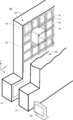
- FIG. 1 An overall perspective view of the automatic warehouse system 20 according to the first embodiment is shown in FIG. In order to make the moving carriage 50 easy to see, a part of the storage shelf 100 is cut out.
- the automatic warehouse system 20 has a pair of storage shelves 100 having a plurality of storage areas RC.
- the storage shelf 100 includes a storage area RC in which the luggage BG is stored and a storage area RC in which the luggage BG is not stored.
- the mobile carriage 50 carries a certain baggage BG into a predetermined storage area RC from a carry-in / out port 101 (see FIG. 2) or loads a baggage BG stored in the storage area RC in accordance with a movement instruction from the control unit MA. Carrying out to the loading / unloading port 101.
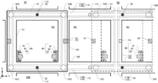
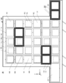
- FIG. 2A is a side view of one of the pair of storage shelves 100 as viewed from the Y-axis direction
- FIG. 2B is a side view of the pair of storage shelves 100 as viewed from the X-axis direction.
- the storage shelf 100 is assembled by a plurality of columns 103 extending in the Z-axis direction and a plurality of beams 105 extending horizontally.
- a plurality of storage areas RC are formed by the columns 103 and the beams 105.
- the number of rows and the number of rows in the storage area RC are arbitrary, and are appropriately increased or decreased according to the installation space.
- a loading / unloading port 101 is provided for loading the baggage BG into and out of the moving vehicle 50.
- a guide rail 110 extending vertically and horizontally is disposed on the support column 103 and the beam 105.
- the guide rail 110 has an axial rail 110A that is narrow and disposed outside the storage area RC, and a roller rail 110B that is wide and disposed inside the storage area RC (see FIG. 3). ).
- the guide roller 52 of the movable carriage 50 enters the roller rail 110B.
- a plurality of lock holes 112 are formed in the horizontally extending guide rail 110. As shown in FIG. 2A, lock holes 112 are formed above and below each storage area RC in the vicinity of the center in the X-axis direction of each storage area RC.
- the movable carriage 50 has a size that substantially matches the size (XZ plane) of one storage area RC.
- the movable carriage 50 has a frame body 51. At least one surface in the Y-axis direction of the frame 51 is open so that the luggage BG can be taken in and out.
- eight guide rollers 52 are attached to one frame 51.
- the four guide rollers 52 are arranged in the ⁇ Y-axis direction from the frame body 51 so as to be supported by the pair of storage shelves 100 (two guide rollers 52 are shown in FIG. 2B).
- the two guide rollers 52 are arranged in the + Y-axis direction from the frame body 51 (two guide rollers 52 are shown in FIG. 2B).
- the eight guide rollers 52 enter the roller rail 110B of the guide rail 110. Since the diameter of the guide roller 52 is larger than the width of the shaft rail 110A, the guide roller 52 does not fall off the guide rail 110 (see FIG. 3). Further, since the size of the load BG carried by the mobile carriage 50 and the size of the load BG stored in the storage area RC are the same, the width WY1 of the storage rack 100 in the Y-axis direction and the Y-direction of the mobile carriage 50 in the Y-axis direction. The width WY2 is almost the same.
- a plurality of mobile trolleys 50 are arranged on the storage shelf 100.
- usually only one stacker crane can be arranged for one traveling guide rail.
- the only way to increase the transport efficiency of the load BG is to increase the moving speed of the stacker crane itself.
- a plurality of movable carriages 50 can be arranged on the storage shelf 100. For this reason, the number of the mobile carriages 50 can be adjusted according to the conveyance frequency of the luggage BG.
- FIG. 3 is an enlarged side view of the storage shelf 100 and the movable carriage 50 as seen from the Y-axis direction.
- FIG. 4 is a view showing guide rollers 52 (52C, 52D, 52E), a lock pin 58, a picker 60, and the like provided in the movable carriage 50.
- the frame 51 of the movable carriage 50 is not drawn in order to make the guide roller 52 easy to see.
- the moving carriage 50 indicated by a dotted line depicts the movement from one storage area RC to another storage area RC
- the moving carriage 50 indicated by a solid line represents one storage area RC. It depicts the state where you can take in and out your luggage.
- the guide roller 52 is driven by a drive motor 55 (see FIG. 4) based on a command from the control unit MA (see FIG. 1).
- the movable carriage 50 has a position sensor SE at the center of the left and right sides in the Z-axis direction within the frame 51.
- a position index PO that is a position detection target of the position sensor SE is disposed on the support column 103.
- the position where the position sensor SE and the position index PO overlap is a position where the movable carriage 50 can take in and out the luggage BG in the storage area RC.
- the moving carriage 50 has a pair of pickers 60 arranged inside the frame 51.
- the pair of pickers 60 puts the package BG into the storage area RC from the frame 51 and takes the package BG from the storage area RC into the frame 51.
- the picker 60 has a fixed frame 61 and a moving frame 62.
- the moving frame 62 is driven by a picker driving unit 65 such as a motor built in the fixed frame 61.
- the picker driving unit 65 moves the moving frame 62 in the ⁇ Y axis direction.
- Each of the pair of moving frames 62 has claw members 63 (63A, 63B).
- FIG. 4 in one moving frame 62, a state in which the claw member 63B protrudes in a state where the claw member 63A has fallen is depicted.
- the claw member 63 (63A and 63B) is formed in an L shape in plan view, and the claw member 63 is rotatably attached to a support shaft (not shown) provided on the moving frame 62. .
- claw member 63 switches to the state which protruded in the X-axis direction, and the state which fell down by the drive part not shown.
- the picker 60 can transfer the luggage BG from the mobile carriage 50 to the storage area RC.
- the claw member 63A protrudes in the X axis direction, and in this state, when the moving frame 62 returns in the + Y axis direction, The claw member 63B pulls the luggage BG from the storage area RC to the moving carriage 50.
- the movable carriage 50 has a fixing pin 58 at the center of the upper and lower sides in the X axis direction of the inside 51 of the frame.
- a lock hole 112 is formed at a central position for each storage area RC of the guide rail 110 that extends horizontally by the beam 105.
- a fixing pin 58 can be inserted into the lock hole 112.
- an actuator 59 such as an electromagnetic solenoid is attached to the fixing pin 58.
- the fixing pin 58 is moved in the ⁇ Y-axis direction by the actuator 59.
- the guide roller 52 is connected to the rotating shaft 56 of the drive motor 55.
- the rotating shaft 56 is supported via a thrust bearing 53.
- the drive motor 55 rotates, the guide roller 52 rotates clockwise or counterclockwise as indicated by a rotation arrow.
- the drive motor 55 is placed on the Y-axis movement table 54.
- the Y-axis moving table 54 can be moved in the ⁇ Y-axis direction by a driving means (not shown). For this reason, the drive motor 55 can move in the ⁇ Y-axis direction, and the rotary shaft 56 can also move in the ⁇ Y-axis direction via the thrust bearing 53. That is, the guide roller 52 is movable in the ⁇ Y axis direction.
- the movable carriage 50 is sandwiched between a pair of storage shelves 100 as shown in FIG.
- the guide rollers 52C and 52E can be moved in the ⁇ Y-axis directions by the Y-axis moving tables 54 on both storage shelves 100 side.
- the drive motor 55 can change the rotation speed of the guide roller 52 by changing the drive pulse or current. Therefore, the control unit MA (see FIG. 1) can change the moving speed of the moving carriage 50.
- FIG. 5 is a view showing the relationship between the guide roller 52 (52C, 52D) and the fixing pin 58 and the guide rail 110 formed on the beam 105.
- FIG. 5A and 5B show a state in which the side surface 52K on the Y-axis side of the guide roller 52 is in contact with the roller rail 110B, and the fixing pin 58 is inserted into the lock hole 112.
- FIG. 5A is a view seen from the Z-axis direction
- FIG. 5B is a view seen from the X-axis direction.
- 5C and 5D show a state in which the guide roller 52 is located at the center of the roller rail 110B in the Y-axis direction, and the fixing pin 58 is removed from the lock hole 112.
- FIG. FIG. 5C is a view seen from the Z-axis direction
- FIG. 5D is a view seen from the X-axis direction.
- the Y-axis moving table 54 moves the guide roller 52 in the ⁇ Y-axis direction.
- the side surface 52K of the guide roller 52 comes into contact with the roller rail 110B.
- the Y-axis moving table 54 on the other storage shelf 100 side moves the guide roller 52 (such as the guide roller 52E in FIG. 4) in the + Y-axis direction. Therefore, the four guide rollers 52 on the one storage shelf 100 side (the guide rollers 52C and 52D are drawn in FIG. 5A) move in the ⁇ Y-axis direction, and 4 on the other storage shelf 100 side.
- the movable carriage 50 is fixed at the position indicated by the solid line.
- the fixing pin 58 is moved in the ⁇ Y-axis direction by the actuator 59 on the one storage shelf 100 side.
- the fixing pin 58 is moved in the + Y-axis direction by the actuator 59 on the other storage shelf 100 side.
- Each fixing pin 58 is inserted into the lock hole 112 of the guide rail 110. Therefore, the movable carriage 50 is fixed at the position indicated by the solid line.
- the guide roller 52 is moved to the roller rail 110B. It is in the position which does not contact.
- the eight guide rollers 52 support the movable carriage 50 in the Z-axis direction within the roller rail 110 ⁇ / b> B extending horizontally of the beam 105. Further, the fixing pin 58 is disengaged from the lock hole 112 of the guide rail 110.
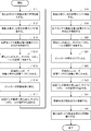
- FIG. 6 is a flowchart showing the operation of loading and unloading the luggage BG by the automatic warehouse system 20.
- this flowchart an operation in which one mobile carriage 50 carries a load BG into the storage area RC and carries out another load BG from the storage area RC will be described.
- step S ⁇ b> 11 the mobile carriage 50 carries the luggage BG at the carry-in / out port 101 (see FIG. 2).
- step S12 the guide roller 52 rotates according to an instruction from the control unit MA, and the movable carriage 50 moves to a predetermined storage area RC.
- the position sensor SE detects the position index PO.
- the position sensor SE confirms the position index PO
- a signal is sent to the control unit MA, and the control unit MA confirms the position of the moving carriage 50 during movement.
- step S13 the control unit MA sends a signal from the position sensor SE, and confirms whether the mobile carriage 50 is accurately moved to the predetermined storage area RC.
- the control unit MA recognizes that the movable carriage 50 is a position where the luggage BG can be taken in and out in the storage area RC.
- step S14 the control unit MA instructs the actuator 59 to project the two fixing pins 58.
- the fixing pin 58 is inserted into the lock hole 112 of the guide rail 110.
- the control unit MA moves the four guide rollers 52 in the + Y-axis direction and moves the four guide rollers 52 in the -Y-axis direction so that the side surface 52K of the guide roller 52 contacts the wall surface in the roller rail 110B.
- the movable carriage 50 is fixed to the storage area RC.
- step S ⁇ b> 15 the picker 60 puts the luggage BG from the frame body 51 of the moving carriage 50 into the storage area RC.
- step S ⁇ b> 16 the picker 60 returns to the mobile carriage 50 while leaving the luggage BG in the storage area.
- step S17 since the moving carriage 50 moves to the next storage area RC, the protruding fixing pin 58 returns to the frame 51 side of the moving carriage 50. Similarly, the guide roller 52 moves in the Y-axis direction, and the side surface 52K of the guide roller 52 is separated from the wall surface of the roller rail 110B. The guide roller 52 moves to substantially the center within the width of the roller rail 110B.
- step S18 the guide roller 52 is rotated by the drive motor 55, and the movable carriage 50 moves to the next storage area RC.
- the position sensor SE detects the position index PO.
- the position sensor SE confirms the position index PO
- a signal is sent to the control unit MA, and the control unit MA confirms the position of the moving carriage 50 during movement.
- step S ⁇ b> 19 the control unit MA confirms whether or not the movable carriage 50 is accurately moved to the next storage area RC based on the signal from the position sensor SE.
- step S ⁇ b> 20 the fixing pin 58 protrudes and the fixing pin 58 is inserted into the lock hole 112. Further, the guide roller 52 moves in the Y-axis direction, and the side surface 52K is brought into contact with the wall surface in the roller rail 110B.
- step S21 the picker 60 (more precisely, the moving frame 62 of the picker 60 moves relative to the fixed frame 61) moves in the Y-axis direction and enters the storage area RC.
- the claw member 63 protrudes in the X-axis direction.
- step S ⁇ b> 22 the luggage BG is hooked by the claw member 63 of the picker 60 to put the luggage BG from the storage area RC into the frame 51 of the moving carriage 50.
- step S ⁇ b> 23 since the movable carriage 50 returns to the carry-in / out port 101, the protruding fixing pin 58 returns to the frame 51 side of the movable carriage 50. Similarly, the guide roller 52 moves to approximately the center within the width of the roller rail 110B. In step S ⁇ b> 24, the guide roller 52 rotates according to an instruction from the control unit MA, and the movable carriage 50 moves to the carry-in / out port 101. In step S ⁇ b> 25, the luggage BG is unloaded from the moving carriage 50 at the loading / unloading port 101.
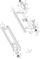
- FIG. 7 is an enlarged side view of the storage shelf 100 and the movable carriage 50 as seen from the Y-axis direction.
- FIG. 8 is a view showing the guide roller 152, the picker 60, and the like provided in the movable carriage 50.
- the frame 51 of the movable carriage 50 is not drawn in order to make the guide roller 152 easier to see.
- the structure of the picker 60 is the same as that described with reference to FIG.
- the moving carriage 50 indicated by a dotted line depicts the middle of moving in the horizontal direction from one storage area RC to another storage area RC.
- a moving carriage 50 indicated by a solid line depicts the middle of moving vertically from one storage area RC to another storage area RC.
- the guide rollers 152 move to the central area of the horizontal side of the XZ plane. ing. As shown in FIG. 7, the guide roller 152A moves by a distance LL1 in the + X axis direction, and the guide roller 152B moves by a distance LL1 in the -X axis direction. The guide roller 152C moves by a distance LL2 in the + X-axis direction, and the guide roller 152D moves by a distance LL2 in the -X-axis direction. The distance LL1 and the distance LL2 are different.
- the two guide rollers 152A and 152C come to the intersection of the vertically extending guide rail 110 and the horizontally extending guide rail 110, the two guide rollers 152B and 152D (the other one) It is necessary to support the mobile carriage 50 in the Z-axis direction with four items including the storage shelf side.
- the movable carriage 50 can be supported in the Z-axis direction by at least three rollers 152 (six including the other storage shelf side).
- the guide roller 152 is connected to the rotation shaft 56 of the drive motor 55.
- the rotating shaft 56 is supported via a thrust bearing 53.
- the thrust bearing 53 and the drive motor 55 are mounted on the X-axis moving table 154.
- the X-axis movement table 154 can be moved by the distance LL1 or the distance LL2 in the ⁇ X-axis direction by a driving unit (not shown). For this reason, the drive motor 55 can move in the ⁇ X-axis direction, and the guide roller 152 can move the distance LL1 or the distance LL2 in the ⁇ X-axis direction.
- the movable carriage 50 is sandwiched between a pair of storage shelves 100 as shown in FIG.
- the guide rollers 152C and 152E can be moved in the ⁇ X-axis directions by the X-axis moving table 154 on both storage shelves 100 side.
- the automatic warehouse system 22 has a plurality of storage shelves 100 (100A to 100D).
- FIG. 9 is a side view of the automatic warehouse system 22 as viewed from the X-axis direction.
- the automatic warehouse system 22 has four storage shelves 100 (100A to 100D) having a plurality of storage areas RC.
- a plurality of movable carriages 50 are arranged between the storage shelves 100A and 100B.
- a plurality of mobile trolleys 50 are disposed between the storage shelves 100B and 100C, and a plurality of mobile trolleys 50 are disposed between the storage shelves 100C and 100D.
- the width WY1 of the storage shelf 100 in the Y-axis direction and the width WY2 of the movable carriage 50 in the Y-axis direction are substantially the same.
- a plurality of mobile carriages 50 are arranged on both sides.
- the picker 60 (more precisely, the moving frame 62) can be moved in the ⁇ Y-axis direction with respect to the fixed frame 61 by the picker driving unit 65. . Therefore, the movable carriage 50 on the left side ( ⁇ Y-axis side) of the storage shelf 100B can take in and out the luggage BG with respect to the storage shelf 100B. Further, the right side (+ Y-axis side) movable carriage 50 of the storage shelf 100B can load and unload the luggage BG with respect to the storage shelf 100B. The same applies to the mobile carts 50 on both sides of the storage shelf 100C.
- the luggage BG can be transported by a plurality of mobile carts 50. Although not shown in FIG. 9, it goes without saying that five or more storage shelves 100 may be arranged.
- the automatic warehouse system 24 has a plurality of storage shelves 100 (100A to 100D).
- FIG. 10 is a side view of the automatic warehouse system 24 viewed from the X-axis direction.
- the automatic warehouse system 24 has four storage shelves 100 (100A to 100D) having a plurality of storage areas RC.
- a plurality of movable carriages 50 are arranged between the storage shelves 100A and 100B.
- Storage shelf 100B and storage shelf 100C are adjacent to each other, and there is no space for mobile carriage 50.
- a plurality of movable carriages 50 are arranged between the storage shelves 100C and 100D.
- the width WY1 of the storage shelf 100 in the Y-axis direction and the width WY2 of the movable carriage 50 in the Y-axis direction are substantially the same.
- the movable carriage 50 on the left side ( ⁇ Y axis side) of the storage shelf 100B can take in and out the luggage BG with respect to the storage shelf 100B.
- the mobile cart 50 on the right side (+ Y-axis side) of the storage shelf 100C can take in and out the luggage BG with respect to the storage shelf 100C.
- the storage shelf 100B and the storage shelf 100C are adjacent to each other, and the luggage BG can be taken in and out without the moving carriage 50 between the storage shelf 100B and the storage shelf 100C.
- the width WY2 of the movable carriage 50 in the Y-axis direction can be reduced, and a limited space can be used effectively.
- the automatic warehouse system 26 according to the fourth embodiment has a storage shelf 130.
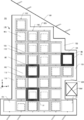
- FIG. 11 is a side view of the automatic warehouse system 26 as viewed from the Y-axis direction.
- the same members as those in the first embodiment are denoted by the same reference numerals.
- the storage shelf 130 is assembled by a plurality of columns 103 extending in the Z-axis direction and a plurality of beams 105 extending horizontally.
- a plurality of storage areas RC are formed by the columns 103 and the beams 105. Similar to the first embodiment, a guide rail 110 and a lock hole 112 are formed.
- the number of rows and the number of rows in the storage area RC are arbitrary, and are appropriately increased or decreased according to the installation space.
- a loading / unloading port 107 is provided for loading the luggage BG into and out of the movable carriage 150.
- the carry-in / out port 107 is provided in a size corresponding to two storage areas so as to fit the size of the movable carriage 150.
- the moving carriage 150 has a size that substantially matches the size (XZ plane) of the two storage areas RC arranged horizontally.
- the movable carriage 150 has a frame 151.
- the two surfaces in the Y-axis direction of the frame 151 are open so that the luggage BG can be taken in and out.
- twelve guide rollers 52 are attached to one frame 151.
- the mobile carriage 150 can carry twice as much luggage BG.
- the mobile carriage 150 has a size corresponding to two storage areas arranged horizontally, but may be more than three storage areas.
- the movable carriage 150 may be two storage areas or three or more storage areas arranged vertically.
- the automatic warehouse system 28 according to the fifth embodiment has a storage shelf 140.
- FIG. 12 is a side view of the automatic warehouse system 28 as viewed from the Y-axis direction.
- the same members as those in the first embodiment are denoted by the same reference numerals.
- the building that houses the automatic warehouse system has an oblique ceiling and multiple pillars. Even in such a case, conventionally, the storage shelf is often substantially rectangular when viewed from the Y-axis direction. In this case, the space between the ceiling and the storage shelf and the space between the pillar and the storage shelf are not effectively used.
- the fifth embodiment is an example in which the storage shelf 140 effectively uses the space between the ceiling and the storage shelf and the space between the pillar and the storage shelf.
- the storage shelf 140 is assembled by a plurality of columns 103 extending in the Z-axis direction and a plurality of beams 105 extending horizontally.
- a plurality of storage areas RC are formed by the columns 103 and the beams 105.
- a guide rail 110 and a lock hole 112 are formed.
- the ceiling RF is slanted and a horizontal pillar BM extending in the Y-axis direction is arranged.
- the support column 103 and the beam 105 are combined within a range that does not interfere with the ceiling RF or the horizontal column BM.
- the storage area RC is also formed in the space on the left side of the ceiling RF, and the storage area RC is also formed on the horizontal pillar BM.
- the movement range of the stacker crane in the Z-axis direction and the X-axis direction is limited to the lowest height of the ceiling RF and the range without the horizontal column BM. It was.
- the movable carriage 50 moves along the guide rails 110 disposed on the columns 103 and the beams 105, the movable carriage 50 can move within the range in which the columns 103 and the beams 105 are assembled.
- the fixed pin and the guide roller are moved in the Y-axis direction so as not to impose a load on the drive motor.
- at least one of the fixed pin and the guide roller may be moved in the Y-axis direction.
- the movable carriage is sandwiched between the storage shelves and supported by the eight guide rollers, the movable carriage may be supported by the cantilever of the four guide rollers.
Abstract
The purpose of the present invention is to provide an automated warehouse system requiring a reduced space. An automated warehouse system (20) is configured so that loads (BG) are stored in storage areas (RC) which are formed by vertically extending supports (103) and horizontally extending beams (105). The loads are loaded into the storage areas, and the loads are unloaded from storage areas. The automated warehouse system comprises: vertical guide rails (110) which are disposed on the supports; lateral guide rails (110) which are disposed on the beams; and a movable platform (50) which has a frame body (51) and guide rollers (52), the frame body (51) having the same rectangular shape as at least one of the storage areas and having vertical frame members and lateral frame members, the guide rollers (52) being either disposed on the vertical frame members and engaging with the vertical guide rails or disposed on the lateral frame members and engaging with the lateral beams.
Description
本発明は、自動倉庫システムに係り、特に、保管エリアに格納された荷物を移載する自動倉庫システムに関するものである。
The present invention relates to an automatic warehouse system, and more particularly to an automatic warehouse system for transferring packages stored in a storage area.
従来の自動倉庫システムにおいては、移載手段として荷昇降式のスタッカークレーンが用いられることが多い。このスタッカークレーンは、走行案内レールに沿って駆動され、また走行案内レールに対して垂直に設けられるガイドフレーム部に沿って上下するよう構成される。そして、スタッカークレーンが一列に配置された複数の保管エリアのそれぞれに対して移動できるように、走行案内レールは一列に配置された保管エリアの端から端まで敷設されている。このようなスタッカークレーンを用いる自動倉庫システムは大きな空間を必要とし、且つ、1つの走行案内レールに対して1つのスタッカークレーンしか配置できないことが多い。自動倉庫システムにおいては、省スペース化又はコンパクト化が求められており、スタッカークレーン及び複数の保管エリアを含めた大きさは小さいほど好ましい。
In a conventional automatic warehouse system, a load raising / lowering stacker crane is often used as a transfer means. The stacker crane is driven along a travel guide rail and is configured to move up and down along a guide frame portion provided perpendicular to the travel guide rail. The travel guide rails are laid from end to end of the storage areas arranged in a row so that the stacker crane can move with respect to each of the plurality of storage areas arranged in a row. Such an automatic warehouse system using a stacker crane requires a large space, and often only one stacker crane can be arranged for one traveling guide rail. In the automatic warehouse system, space saving or downsizing is required, and the size including the stacker crane and the plurality of storage areas is preferably as small as possible.
しかしながら、自動倉庫システムの移載手段として荷昇降式のスタッカークレーンを用いる場合、スタッカークレーン用の移動レールを用意しなくてはならず倉庫の省スペース化、コンパクト化には限界があった。また荷物の取り出し量を多くするために複数のスタッカークレーンを配置すると、さらに別の移動レールを用意しなくてはならず省スペース化が困難であった。
However, in the case of using a load raising / lowering stacker crane as a transfer means of an automatic warehouse system, a moving rail for the stacker crane must be prepared, and there is a limit to space saving and compactness of the warehouse. In addition, when a plurality of stacker cranes are arranged to increase the amount of luggage taken out, it is difficult to save space because another moving rail must be prepared.
そこで、本発明は、省スペース化した自動倉庫システムを提供する。
Therefore, the present invention provides an automatic warehouse system that saves space.
第1観点の自動倉庫システムは、垂直に伸びる複数の支柱と水平に伸びる複数の梁とによって組み上げられた複数の保管エリアに荷物を格納し、複数の保管エリアに荷物を搬入し且つ複数の保管エリアから荷物を搬出する。そして自動倉庫システムは、支柱に配置された縦ガイドレールと、梁に配置された横ガイドレールと、少なくとも1つの保管エリアと同じ矩形状の縦枠及び横枠を有する枠体と、縦枠に配置され縦ガイドレール又は横枠に配置され横ガイドレールと係合するガイドローラとを有する移動台車と、を備える。
移動台車が縦ガイドレールと横ガイドレールと沿って進むため、床面にスタッカークレーン用の走行案内レールを配置する必要がない。また、複数の移動台車を縦ガイドレールと横ガイドレールとに配置することも可能になる。 The automatic warehouse system according to the first aspect stores luggage in a plurality of storage areas assembled by a plurality of vertically extending columns and a plurality of beams extending horizontally, and loads the plurality of storage areas into a plurality of storage areas. Unload luggage from the area. The automatic warehouse system includes a vertical guide rail disposed on the column, a horizontal guide rail disposed on the beam, a frame having the same rectangular vertical frame and horizontal frame as at least one storage area, and a vertical frame. A movable carriage having a guide roller arranged and arranged in a vertical guide rail or a horizontal frame and engaged with the horizontal guide rail.
Since the movable carriage moves along the vertical guide rail and the horizontal guide rail, there is no need to arrange a travel guide rail for the stacker crane on the floor surface. In addition, a plurality of movable carriages can be arranged on the vertical guide rail and the horizontal guide rail.
第2観点の自動倉庫システムでは、移動台車は荷物をスライドさせて移動台車から保管エリアに入れ且つ荷物をスライドさせて保管エリアから移動台車に出すピィッカーを有する。
第3観点の自動倉庫システムでは、ガイドローラは枠体の矩形状の角部に配置され且つ縦ガイドレール及び横ガイドレールに交差する方向に移動可能になっており、荷物を搬入又は搬出する際には、ガイドローラは縦ガイドレール又は横ガイドレールに押し付けられる。これにより移動台車は保管エリアに固定される。
第4観点の自動倉庫システムは、荷物を搬入又は搬出する際には、横ガイドレールと移動台車とを互いに固定する固定装置を有する。これにより移動台車は保管エリアに固定される。 In the automatic warehouse system according to the second aspect, the moving carriage has a picker that slides the luggage into the storage area from the moving carriage and slides the luggage out from the storage area to the moving carriage.
In the automatic warehouse system according to the third aspect, the guide roller is arranged at the rectangular corner of the frame and is movable in the direction intersecting the vertical guide rail and the horizontal guide rail. In this case, the guide roller is pressed against the vertical guide rail or the horizontal guide rail. As a result, the movable carriage is fixed in the storage area.
The automatic warehouse system according to the fourth aspect includes a fixing device that fixes the lateral guide rail and the movable carriage to each other when carrying or unloading the luggage. As a result, the movable carriage is fixed in the storage area.
第5観点の自動倉庫システムでは、ガイドローラは枠体の水平方向の辺から枠体の矩形状の角部に移動可能になっており、荷物を搬入又は搬出する際及び移動台車が横方向に移動する際には、ガイドローラは水平方向の辺の中央領域にあり、移動台車が縦方向に移動する際には、ガイドローラは角部の位置にある。
第6観点の自動倉庫システムでは、ガイドローラは第1ガイドローラと第2ガイドローラとを含み、第1ガイドローラの中央領域から角部への移動距離と第2ガイドローラの中央領域から角部への移動距離とが異なる。 In the automatic warehouse system according to the fifth aspect, the guide roller is movable from the horizontal side of the frame to the rectangular corner of the frame, and the carriage is moved in the horizontal direction when loading or unloading the load. When moving, the guide roller is in the central region of the horizontal side, and when the moving carriage moves in the vertical direction, the guide roller is at the corner.
In the automatic warehouse system according to the sixth aspect, the guide roller includes a first guide roller and a second guide roller, and the distance from the central region to the corner of the first guide roller and the corner from the central region of the second guide roller The moving distance to is different.
第7観点の自動倉庫システムでは、移動台車は、複数の保管エリアからなる第1保管棚と該第1保管棚に対向して配置され複数の保管エリアからなる第2保管棚とに挟まれるように配置されており、ガイドローラは、第1保管棚側と第2保管棚側に配置される。
第8観点の自動倉庫システムでは、移動台車は、複数の保管エリアからなる第3保管棚と該第3保管棚に対向して配置され複数の保管エリアからなる第4保管棚とに挟まれるように配置されており、第2保管棚と第3保管棚とが隣り合って配置されている。
第9観点の自動倉庫システムでは、移動台車は隣り合う複数の保管エリアに対応する枠体を有する。 In the automatic warehouse system according to the seventh aspect, the mobile carriage is sandwiched between a first storage shelf composed of a plurality of storage areas and a second storage shelf composed of a plurality of storage areas arranged opposite to the first storage shelf. The guide rollers are arranged on the first storage shelf side and the second storage shelf side.
In the automatic warehouse system according to the eighth aspect, the mobile carriage is sandwiched between a third storage shelf composed of a plurality of storage areas and a fourth storage shelf composed of a plurality of storage areas arranged opposite to the third storage shelf. The second storage shelf and the third storage shelf are arranged next to each other.
In the automatic warehouse system according to the ninth aspect, the movable carriage has a frame corresponding to a plurality of adjacent storage areas.
本発明の自動倉庫システムは、少ない床面積で保管エリアへ荷物を搬入したり、保管エリアから荷物を搬出したりできる。
The automatic warehouse system according to the present invention can carry luggage into and out of the storage area with a small floor area.
(第1実施形態)
以下、第1実施形態を添付図面に基づいて説明する。
第1実施形態に係る自動倉庫システム20の全体斜視図を図1に示す。移動台車50を見やすくするため、保管棚100の一部を切り欠いて描いてある。 (First embodiment)
Hereinafter, a first embodiment will be described with reference to the accompanying drawings.
An overall perspective view of theautomatic warehouse system 20 according to the first embodiment is shown in FIG. In order to make the moving carriage 50 easy to see, a part of the storage shelf 100 is cut out.
以下、第1実施形態を添付図面に基づいて説明する。
第1実施形態に係る自動倉庫システム20の全体斜視図を図1に示す。移動台車50を見やすくするため、保管棚100の一部を切り欠いて描いてある。 (First embodiment)
Hereinafter, a first embodiment will be described with reference to the accompanying drawings.
An overall perspective view of the
<自動倉庫システム20の構成>
図1に示されるように、第1実施形態に係る自動倉庫システム20は、複数の保管エリアRCを有する一対の保管棚100を有している。保管棚100には、荷物BGが保管されている保管エリアRCと、荷物BGが保管されていない保管エリアRCとがある。移動台車50は、制御部MAの移動指示に従って、ある荷物BGを搬入出ポート101(図2を参照。)から所定の保管エリアRCへ搬入したり、保管エリアRCに保管されている荷物BGを搬入出ポート101へ搬出したりする。 <Configuration ofautomatic warehouse system 20>
As shown in FIG. 1, theautomatic warehouse system 20 according to the first embodiment has a pair of storage shelves 100 having a plurality of storage areas RC. The storage shelf 100 includes a storage area RC in which the luggage BG is stored and a storage area RC in which the luggage BG is not stored. The mobile carriage 50 carries a certain baggage BG into a predetermined storage area RC from a carry-in / out port 101 (see FIG. 2) or loads a baggage BG stored in the storage area RC in accordance with a movement instruction from the control unit MA. Carrying out to the loading / unloading port 101.
図1に示されるように、第1実施形態に係る自動倉庫システム20は、複数の保管エリアRCを有する一対の保管棚100を有している。保管棚100には、荷物BGが保管されている保管エリアRCと、荷物BGが保管されていない保管エリアRCとがある。移動台車50は、制御部MAの移動指示に従って、ある荷物BGを搬入出ポート101(図2を参照。)から所定の保管エリアRCへ搬入したり、保管エリアRCに保管されている荷物BGを搬入出ポート101へ搬出したりする。 <Configuration of
As shown in FIG. 1, the
図2(A)は一対の保管棚100の一方をY軸方向から見た側面図であり、図2(B)は一対の保管棚100をX軸方向から見た側面図である。
2A is a side view of one of the pair of storage shelves 100 as viewed from the Y-axis direction, and FIG. 2B is a side view of the pair of storage shelves 100 as viewed from the X-axis direction.
図2(A)に示されるように、保管棚100はZ軸方向に伸びる複数の支柱103と水平に伸びる複数の梁105とによって組み上げられている。この支柱103と梁105とによって複数の保管エリアRCが形成されている。保管エリアRCの段数、列数は任意であり、設置スペースに応じて適宜増減される。一番下(-Z軸側)の段の棚の左右には、移動台車50へ荷物BGを搬入したり移動台車50から荷物BGを搬出したりする搬入出ポート101が設けられている。
As shown in FIG. 2A, the storage shelf 100 is assembled by a plurality of columns 103 extending in the Z-axis direction and a plurality of beams 105 extending horizontally. A plurality of storage areas RC are formed by the columns 103 and the beams 105. The number of rows and the number of rows in the storage area RC are arbitrary, and are appropriately increased or decreased according to the installation space. On the left and right sides of the lowest (−Z-axis side) shelf, a loading / unloading port 101 is provided for loading the baggage BG into and out of the moving vehicle 50.
支柱103と梁105とには、垂直及び水平に伸びるガイドレール110が配置されている。ガイドレール110は幅が細く各保管エリアRCに対して外側に配置される軸レール110Aと幅が広く各保管エリアRCに対して内側に配置されるローラレール110Bとを有する(図3を参照。)。ローラレール110Bには移動台車50のガイドローラ52が入り込む。水平に伸びるガイドレール110には、ロック孔112が複数形成されている。図2(A)に示されるように各保管エリアRCのX軸方向の中央付近でその各保管エリアRCの上下にロック孔112が形成される。
A guide rail 110 extending vertically and horizontally is disposed on the support column 103 and the beam 105. The guide rail 110 has an axial rail 110A that is narrow and disposed outside the storage area RC, and a roller rail 110B that is wide and disposed inside the storage area RC (see FIG. 3). ). The guide roller 52 of the movable carriage 50 enters the roller rail 110B. A plurality of lock holes 112 are formed in the horizontally extending guide rail 110. As shown in FIG. 2A, lock holes 112 are formed above and below each storage area RC in the vicinity of the center in the X-axis direction of each storage area RC.
図2(A)及び(B)に示されるように、移動台車50は1つの保管エリアRCの大きさ(XZ平面)にほぼ一致する大きさである。そして移動台車50は枠体51を有している。荷物BGを出し入れできるように枠体51の少なくとも1つのY軸方向の面は開いている。また1つの枠体51には8つのガイドローラ52が取り付けられている。一対の保管棚100で支えられるように、4つのガイドローラ52は枠体51から-Y軸方向に配置されており(図2(B)では2つのガイドローラ52が図示されている)、4つのガイドローラ52は枠体51から+Y軸方向に配置されている(図2(B)では2つのガイドローラ52が図示されている)。この8つのガイドローラ52はガイドレール110のローラレール110Bに入り込んでいる。ガイドローラ52の直径は、軸レール110Aの幅より大きいため、ガイドローラ52がガイドレール110から外れて落ちることがない(図3を参照。)。また、移動台車50が搬送する荷物BGの大きさ及び保管エリアRCで保管する荷物BGの大きさは同じであるため、保管棚100のY軸方向の幅WY1と移動台車50のY軸方向の幅WY2とはほぼ同じである。
As shown in FIGS. 2 (A) and 2 (B), the movable carriage 50 has a size that substantially matches the size (XZ plane) of one storage area RC. The movable carriage 50 has a frame body 51. At least one surface in the Y-axis direction of the frame 51 is open so that the luggage BG can be taken in and out. Further, eight guide rollers 52 are attached to one frame 51. The four guide rollers 52 are arranged in the −Y-axis direction from the frame body 51 so as to be supported by the pair of storage shelves 100 (two guide rollers 52 are shown in FIG. 2B). The two guide rollers 52 are arranged in the + Y-axis direction from the frame body 51 (two guide rollers 52 are shown in FIG. 2B). The eight guide rollers 52 enter the roller rail 110B of the guide rail 110. Since the diameter of the guide roller 52 is larger than the width of the shaft rail 110A, the guide roller 52 does not fall off the guide rail 110 (see FIG. 3). Further, since the size of the load BG carried by the mobile carriage 50 and the size of the load BG stored in the storage area RC are the same, the width WY1 of the storage rack 100 in the Y-axis direction and the Y-direction of the mobile carriage 50 in the Y-axis direction. The width WY2 is almost the same.
図2(A)及び(B)に示されるように、保管棚100には複数の移動台車50が配置されている。従来の自動倉庫システムでは通常1つの走行案内レールに対して1つのスタッカークレーンしか配置できなかった。このため、荷物BGの搬送効率を高めようとすると、スタッカークレーン自体の移動速度を上げる方法しかなかった。しかし、本実施形態では、複数の移動台車50を保管棚100に配置することができる。このため、荷物BGの搬送頻度に応じて移動台車50の数を調整することができる。
As shown in FIGS. 2 (A) and 2 (B), a plurality of mobile trolleys 50 are arranged on the storage shelf 100. In the conventional automatic warehouse system, usually only one stacker crane can be arranged for one traveling guide rail. For this reason, the only way to increase the transport efficiency of the load BG is to increase the moving speed of the stacker crane itself. However, in the present embodiment, a plurality of movable carriages 50 can be arranged on the storage shelf 100. For this reason, the number of the mobile carriages 50 can be adjusted according to the conveyance frequency of the luggage BG.
<ガイドローラ52及び固定ピン58の構成>
図3は保管棚100及び移動台車50をY軸方向から見た側面拡大図である。また、図4は、移動台車50に備え付けられるガイドローラ52(52C,52D,52E)、ロックピン58及びピィッカー60等を示した図である。図4ではガイドローラ52を見やすくするため移動台車50の枠体51が描かれていない。 <Configuration ofguide roller 52 and fixing pin 58>
FIG. 3 is an enlarged side view of thestorage shelf 100 and the movable carriage 50 as seen from the Y-axis direction. FIG. 4 is a view showing guide rollers 52 (52C, 52D, 52E), a lock pin 58, a picker 60, and the like provided in the movable carriage 50. In FIG. 4, the frame 51 of the movable carriage 50 is not drawn in order to make the guide roller 52 easy to see.
図3は保管棚100及び移動台車50をY軸方向から見た側面拡大図である。また、図4は、移動台車50に備え付けられるガイドローラ52(52C,52D,52E)、ロックピン58及びピィッカー60等を示した図である。図4ではガイドローラ52を見やすくするため移動台車50の枠体51が描かれていない。 <Configuration of
FIG. 3 is an enlarged side view of the
図3において、点線で示された移動台車50は、1つの保管エリアRCから別の保管エリアRCへの移動途中を描いたものであり、実線で示された移動台車50は1つの保管エリアRCで荷物を出し入れできる状態を描いたものである。ガイドローラ52は制御部MA(図1を参照。)の指令に基づき駆動モータ55(図4を参照。)によって駆動される。
In FIG. 3, the moving carriage 50 indicated by a dotted line depicts the movement from one storage area RC to another storage area RC, and the moving carriage 50 indicated by a solid line represents one storage area RC. It depicts the state where you can take in and out your luggage. The guide roller 52 is driven by a drive motor 55 (see FIG. 4) based on a command from the control unit MA (see FIG. 1).
移動台車50はその枠内51のZ軸方向の左右の辺の中央に位置センサSEを有している。支柱103には、位置センサSEの位置検出対象となる位置指標POが配置されている。位置センサSEと位置指標POとが重なった位置が、移動台車50が保管エリアRCで荷物BGを出し入れできる位置である。
The movable carriage 50 has a position sensor SE at the center of the left and right sides in the Z-axis direction within the frame 51. A position index PO that is a position detection target of the position sensor SE is disposed on the support column 103. The position where the position sensor SE and the position index PO overlap is a position where the movable carriage 50 can take in and out the luggage BG in the storage area RC.
移動台車50はその枠内51の内側に一対のピィッカー60が配置されている。一対のピィッカー60は荷物BGを枠内51から保管エリアRCに入れたり、荷物BGを保管エリアRCから枠内51に出したりする。
The moving carriage 50 has a pair of pickers 60 arranged inside the frame 51. The pair of pickers 60 puts the package BG into the storage area RC from the frame 51 and takes the package BG from the storage area RC into the frame 51.
図4に示されるように、ピィッカー60は、固定フレーム61と移動フレーム62とを有している。移動フレーム62は固定フレーム61に内蔵したモータ等のピィッカー駆動部65によって駆動される。ピィッカー駆動部65は移動フレーム62を±Y軸方向に移動させる。
As shown in FIG. 4, the picker 60 has a fixed frame 61 and a moving frame 62. The moving frame 62 is driven by a picker driving unit 65 such as a motor built in the fixed frame 61. The picker driving unit 65 moves the moving frame 62 in the ± Y axis direction.
一対の移動フレーム62は、それぞれ爪部材63(63A、63B)を有している。図4では、一方の移動フレーム62において、爪部材63Aが倒れた状態で爪部材63Bが突出した状態が描かれている。爪部材63(63A及び63B)は、平面視でL字状に形成されており、爪部材63は、移動フレーム62に設けられた支軸(不図示)に対して回転可能に装着されている。そして不図示の駆動部によって、爪部材63は、X軸方向に突出した状態と倒れた状態とに切り替わる。
Each of the pair of moving frames 62 has claw members 63 (63A, 63B). In FIG. 4, in one moving frame 62, a state in which the claw member 63B protrudes in a state where the claw member 63A has fallen is depicted. The claw member 63 (63A and 63B) is formed in an L shape in plan view, and the claw member 63 is rotatably attached to a support shaft (not shown) provided on the moving frame 62. . And the nail | claw member 63 switches to the state which protruded in the X-axis direction, and the state which fell down by the drive part not shown.
移動台車50に荷物BGを載せた状態で+Y軸側の一対の爪部材63BをX軸方向に突出させ、その状態で移動フレーム62を-Y軸方向に前進させると、爪部材63Bは荷物BGを-Y軸方向に押す。これにより、ピィッカー60は、荷物BGを移動台車50から保管エリアRCに載せ替えることができる。一方、移動フレーム62を(保管エリアRCに対して)大きく-Y軸方向に前進させた状態で爪部材63AをX軸方向に突出させ、その状態で移動フレーム62が+Y軸方向に戻ると、爪部材63Bは荷物BGを保管エリアRCから移動台車50に引き出す。
When the pair of claw members 63B on the + Y-axis side is protruded in the X-axis direction with the luggage BG placed on the movable carriage 50, and the movable frame 62 is advanced in the −Y-axis direction in this state, the claw members 63B are moved to the luggage BG. Press in the -Y direction. Accordingly, the picker 60 can transfer the luggage BG from the mobile carriage 50 to the storage area RC. On the other hand, when the moving frame 62 is greatly advanced in the −Y axis direction (relative to the storage area RC), the claw member 63A protrudes in the X axis direction, and in this state, when the moving frame 62 returns in the + Y axis direction, The claw member 63B pulls the luggage BG from the storage area RC to the moving carriage 50.
図3に戻り、移動台車50はその枠内51のX軸方向の上下の辺の中央に固定ピン58を有している。また、梁105で水平に伸びるガイドレール110の保管エリアRCごとの中央位置にロック孔112が形成される。ロック孔112には固定ピン58が挿入可能である。
3, the movable carriage 50 has a fixing pin 58 at the center of the upper and lower sides in the X axis direction of the inside 51 of the frame. In addition, a lock hole 112 is formed at a central position for each storage area RC of the guide rail 110 that extends horizontally by the beam 105. A fixing pin 58 can be inserted into the lock hole 112.
また、図4に示されるように、固定ピン58には電磁ソレノイド等のアクチュエータ59が取り付けられている。アクチュエータ59によって固定ピン58は±Y軸方向に移動する。
As shown in FIG. 4, an actuator 59 such as an electromagnetic solenoid is attached to the fixing pin 58. The fixing pin 58 is moved in the ± Y-axis direction by the actuator 59.
再び図3に戻り、ガイドローラ52(52A~52D)は、XZ平面において枠体51の角部に4つ配置されている。実線で示された移動台車50では、4つのガイドローラ52A~52Dは、垂直に伸びるガイドレール110と水平に伸びるガイドレール110との交点に位置する。図2で示されたように移動台車50は一対の保管棚100に挟まれているため合計8つのガイドローラ52が枠体51の角部に配置される。この状態から移動台車50は、Z軸方向にもX軸方向にも移動できる。±Z軸方向に移動する際には2つのガイドローラ52A及び52Cが時計回りに回転し、2つのガイドローラ52B及び52Dが反時計回りに回転する。+X軸方向に移動する際には4つのガイドローラ52A~52Dが時計回りに回転する。-X軸方向に移動する際には4つのガイドローラ52A~52Dが反時計回りに回転する。
3 again, four guide rollers 52 (52A to 52D) are arranged at the corners of the frame 51 in the XZ plane. In the movable carriage 50 indicated by the solid line, the four guide rollers 52A to 52D are located at the intersections of the guide rail 110 extending vertically and the guide rail 110 extending horizontally. As shown in FIG. 2, since the movable carriage 50 is sandwiched between the pair of storage shelves 100, a total of eight guide rollers 52 are arranged at the corners of the frame body 51. From this state, the movable carriage 50 can move both in the Z-axis direction and in the X-axis direction. When moving in the ± Z-axis direction, the two guide rollers 52A and 52C rotate clockwise, and the two guide rollers 52B and 52D rotate counterclockwise. When moving in the + X-axis direction, the four guide rollers 52A to 52D rotate clockwise. -When moving in the X-axis direction, the four guide rollers 52A to 52D rotate counterclockwise.
また図4に示されるように、ガイドローラ52は駆動モータ55の回転軸56に接続されている。回転軸56はスラストベアリング53を介して支持されている。駆動モータ55が回転することでガイドローラ52は回転矢印のように時計又は反時計回りに回転する。また駆動モータ55はY軸移動テーブル54に載置されている。Y軸移動テーブル54は不図示の駆動手段によって±Y軸方向に移動可能である。このため駆動モータ55は±Y軸方向に移動可能であり、回転軸56もスラストベアリング53を介して±Y軸方向に移動可能である。つまりガイドローラ52は±Y軸方向に移動可能である。
As shown in FIG. 4, the guide roller 52 is connected to the rotating shaft 56 of the drive motor 55. The rotating shaft 56 is supported via a thrust bearing 53. As the drive motor 55 rotates, the guide roller 52 rotates clockwise or counterclockwise as indicated by a rotation arrow. The drive motor 55 is placed on the Y-axis movement table 54. The Y-axis moving table 54 can be moved in the ± Y-axis direction by a driving means (not shown). For this reason, the drive motor 55 can move in the ± Y-axis direction, and the rotary shaft 56 can also move in the ± Y-axis direction via the thrust bearing 53. That is, the guide roller 52 is movable in the ± Y axis direction.
なお、移動台車50は図2(B)で示されたように、一対の保管棚100で挟まれている。双方の保管棚100側のY軸移動テーブル54によりガイドローラは52C,52Eともに±Y軸方向に移動可能である。また駆動モータ55は駆動パルス又は電流を変えることによりガイドローラ52の回転速度を変えることができる。そのため制御部MA(図1を参照)は、移動台車50の移動速度を変えることができる。
Note that the movable carriage 50 is sandwiched between a pair of storage shelves 100 as shown in FIG. The guide rollers 52C and 52E can be moved in the ± Y-axis directions by the Y-axis moving tables 54 on both storage shelves 100 side. The drive motor 55 can change the rotation speed of the guide roller 52 by changing the drive pulse or current. Therefore, the control unit MA (see FIG. 1) can change the moving speed of the moving carriage 50.
<ガイドローラ52及び固定ピン58の動作>
次に、図5を使って、ガイドローラ52及び固定ピン58の動作について説明する。図3において、実線で示された移動台車50が保管エリアRCで荷物を出し入れする際に、ガイドローラ52に回転力を与えていないと移動台車50はその自重により-Z軸方向に落ちてしまうおそれがある。常にガイドローラ52に回転力を与え続けることは駆動モータ55に負担が大きい。そこで、駆動モータ55を止めても移動台車50が実線で示された位置に維持されているように、ガイドローラ52と固定ピン58とで移動台車50を支えるようにする。 <Operation ofGuide Roller 52 and Fixing Pin 58>
Next, the operation of theguide roller 52 and the fixing pin 58 will be described with reference to FIG. In FIG. 3, when the moving carriage 50 indicated by the solid line takes in and out the luggage in the storage area RC, the moving carriage 50 falls in the −Z-axis direction due to its own weight unless the rotational force is applied to the guide roller 52. There is a fear. It is a heavy burden on the drive motor 55 to always apply the rotational force to the guide roller 52. Therefore, the movable carriage 50 is supported by the guide roller 52 and the fixed pin 58 so that the movable carriage 50 is maintained at the position indicated by the solid line even when the drive motor 55 is stopped.
次に、図5を使って、ガイドローラ52及び固定ピン58の動作について説明する。図3において、実線で示された移動台車50が保管エリアRCで荷物を出し入れする際に、ガイドローラ52に回転力を与えていないと移動台車50はその自重により-Z軸方向に落ちてしまうおそれがある。常にガイドローラ52に回転力を与え続けることは駆動モータ55に負担が大きい。そこで、駆動モータ55を止めても移動台車50が実線で示された位置に維持されているように、ガイドローラ52と固定ピン58とで移動台車50を支えるようにする。 <Operation of
Next, the operation of the
図5はガイドローラ52(52C、52D)及び固定ピン58と梁105に形成されたガイドレール110との関係を示した図である。図5(A)及び(B)はガイドローラ52のY軸側の側面52Kがローラレール110Bに当接し、さらに固定ピン58がロック孔112に挿入された状態である。そして図5(A)はZ軸方向から見た図であり、(B)はX軸方向から見た図である。図5(C)及び(D)はガイドローラ52がローラレール110BのY軸方向中央に位置し、さらに固定ピン58がロック孔112から外れた状態である。そして図5(C)はZ軸方向から見た図であり、(D)はX軸方向から見た図である。
FIG. 5 is a view showing the relationship between the guide roller 52 (52C, 52D) and the fixing pin 58 and the guide rail 110 formed on the beam 105. FIG. 5A and 5B show a state in which the side surface 52K on the Y-axis side of the guide roller 52 is in contact with the roller rail 110B, and the fixing pin 58 is inserted into the lock hole 112. FIG. 5A is a view seen from the Z-axis direction, and FIG. 5B is a view seen from the X-axis direction. 5C and 5D show a state in which the guide roller 52 is located at the center of the roller rail 110B in the Y-axis direction, and the fixing pin 58 is removed from the lock hole 112. FIG. FIG. 5C is a view seen from the Z-axis direction, and FIG. 5D is a view seen from the X-axis direction.
図5(A)及び(B)に示されるように、移動台車50が図3の実線で示された位置にある際には、Y軸移動テーブル54はガイドローラ52を-Y軸方向に移動させる。そして、ガイドローラ52の側面52Kがローラレール110Bに当接する。図示されていない他方の保管棚100側のY軸移動テーブル54はガイドローラ52(図4のガイドローラ52E等)を+Y軸方向に移動させる。そのため、一方の保管棚100側の4つのガイドローラ52(図5(A)ではガイドローラ52C及び52Dが描かれている)が-Y軸方向に移動し、且つ他方の保管棚100側の4つのガイドローラ52が+Y軸方向に移動することで、移動台車50は実線で示された位置で固定される。
As shown in FIGS. 5A and 5B, when the moving carriage 50 is at the position indicated by the solid line in FIG. 3, the Y-axis moving table 54 moves the guide roller 52 in the −Y-axis direction. Let Then, the side surface 52K of the guide roller 52 comes into contact with the roller rail 110B. The Y-axis moving table 54 on the other storage shelf 100 side (not shown) moves the guide roller 52 (such as the guide roller 52E in FIG. 4) in the + Y-axis direction. Therefore, the four guide rollers 52 on the one storage shelf 100 side (the guide rollers 52C and 52D are drawn in FIG. 5A) move in the −Y-axis direction, and 4 on the other storage shelf 100 side. When the two guide rollers 52 move in the + Y-axis direction, the movable carriage 50 is fixed at the position indicated by the solid line.
また、移動台車50が図3の実線で示された位置にある際には、一方の保管棚100側のアクチュエータ59によって固定ピン58を-Y軸方向に移動させる。他方の保管棚100側のアクチュエータ59によって固定ピン58を+Y軸方向に移動させる。それぞれの固定ピン58はガイドレール110のロック孔112に挿入される。そのため、移動台車50は実線で示された位置で固定される。
Further, when the movable carriage 50 is at the position indicated by the solid line in FIG. 3, the fixing pin 58 is moved in the −Y-axis direction by the actuator 59 on the one storage shelf 100 side. The fixing pin 58 is moved in the + Y-axis direction by the actuator 59 on the other storage shelf 100 side. Each fixing pin 58 is inserted into the lock hole 112 of the guide rail 110. Therefore, the movable carriage 50 is fixed at the position indicated by the solid line.
図5(C)及び(D)に示されるように、移動台車50が図3の点線で示された位置(実線で示された位置以外)にある際には、ガイドローラ52はローラレール110Bに当接しない位置にある。8つのガイドローラ52は梁105の水平に伸びたローラレール110B内で移動台車50をZ軸方向に支えている。また、固定ピン58はガイドレール110のロック孔112から外れている。
As shown in FIGS. 5C and 5D, when the movable carriage 50 is in the position indicated by the dotted line in FIG. 3 (other than the position indicated by the solid line), the guide roller 52 is moved to the roller rail 110B. It is in the position which does not contact. The eight guide rollers 52 support the movable carriage 50 in the Z-axis direction within the roller rail 110 </ b> B extending horizontally of the beam 105. Further, the fixing pin 58 is disengaged from the lock hole 112 of the guide rail 110.
<自動倉庫システム20の動作>
図6は、自動倉庫システム20による荷物BGの搬入及び搬出の動作を示したフローチャートである。このフローチャートでは1台の移動台車50が荷物BGを保管エリアRCに搬入し、別の荷物BGを保管エリアRCから搬出する動作を説明する。 <Operation ofautomatic warehouse system 20>
FIG. 6 is a flowchart showing the operation of loading and unloading the luggage BG by theautomatic warehouse system 20. In this flowchart, an operation in which one mobile carriage 50 carries a load BG into the storage area RC and carries out another load BG from the storage area RC will be described.
図6は、自動倉庫システム20による荷物BGの搬入及び搬出の動作を示したフローチャートである。このフローチャートでは1台の移動台車50が荷物BGを保管エリアRCに搬入し、別の荷物BGを保管エリアRCから搬出する動作を説明する。 <Operation of
FIG. 6 is a flowchart showing the operation of loading and unloading the luggage BG by the
ステップS11では、搬入出ポート101(図2を参照。)で移動台車50が荷物BGを搬入する。
ステップS12では、制御部MAの指示に従いガイドローラ52が回転し、移動台車50が所定の保管エリアRCに移動する。この移動の際に、位置センサSEは位置指標POを検出する。位置センサSEが位置指標POを確認した際には制御部MAに信号が送られ、制御部MAは移動台車50の移動中の位置を確認する。 In step S <b> 11, themobile carriage 50 carries the luggage BG at the carry-in / out port 101 (see FIG. 2).
In step S12, theguide roller 52 rotates according to an instruction from the control unit MA, and the movable carriage 50 moves to a predetermined storage area RC. During this movement, the position sensor SE detects the position index PO. When the position sensor SE confirms the position index PO, a signal is sent to the control unit MA, and the control unit MA confirms the position of the moving carriage 50 during movement.
ステップS12では、制御部MAの指示に従いガイドローラ52が回転し、移動台車50が所定の保管エリアRCに移動する。この移動の際に、位置センサSEは位置指標POを検出する。位置センサSEが位置指標POを確認した際には制御部MAに信号が送られ、制御部MAは移動台車50の移動中の位置を確認する。 In step S <b> 11, the
In step S12, the
ステップS13では、制御部MAは位置センサSEからの信号が送られ、移動台車50が所定の保管エリアRCに正確に移動しているかを確認する。位置センサSEと位置指標POとが重なった状態で、制御部MAは、移動台車50が保管エリアRCで荷物BGを出し入れできる位置であると認識する。
In step S13, the control unit MA sends a signal from the position sensor SE, and confirms whether the mobile carriage 50 is accurately moved to the predetermined storage area RC. In a state where the position sensor SE and the position index PO overlap, the control unit MA recognizes that the movable carriage 50 is a position where the luggage BG can be taken in and out in the storage area RC.
ステップS14では、制御部MAはアクチュエータ59に指示し2つの固定ピン58を突出させる。固定ピン58はガイドレール110のロック孔112に挿入される。また、制御部MAは4つのガイドローラ52を+Y軸方向に残り4つのガイドローラ52を-Y軸方向に移動させ、ガイドローラ52の側面52Kをローラレール110B内の壁面に当接させる。これにより移動台車50が保管エリアRCに対して固定された状態となる。
In step S14, the control unit MA instructs the actuator 59 to project the two fixing pins 58. The fixing pin 58 is inserted into the lock hole 112 of the guide rail 110. Further, the control unit MA moves the four guide rollers 52 in the + Y-axis direction and moves the four guide rollers 52 in the -Y-axis direction so that the side surface 52K of the guide roller 52 contacts the wall surface in the roller rail 110B. Thereby, the movable carriage 50 is fixed to the storage area RC.
ステップS15では、ピィッカー60が荷物BGを移動台車50の枠体51から保管エリアRCに入れる。
ステップS16では、ピィッカー60が保管エリア内に荷物BGを残したまま、移動台車50に戻ってくる。 In step S <b> 15, thepicker 60 puts the luggage BG from the frame body 51 of the moving carriage 50 into the storage area RC.
In step S <b> 16, thepicker 60 returns to the mobile carriage 50 while leaving the luggage BG in the storage area.
ステップS16では、ピィッカー60が保管エリア内に荷物BGを残したまま、移動台車50に戻ってくる。 In step S <b> 15, the
In step S <b> 16, the
ステップS17では、移動台車50が次の保管エリアRCに移動するため、突出していた固定ピン58が移動台車50の枠体51側に戻る。同様に、ガイドローラ52がY軸方向に移動し、そのガイドローラ52の側面52Kがローラレール110Bの壁面から離れる。ガイドローラ52はローラレール110Bの幅内のほぼ中央に移動する。
In step S17, since the moving carriage 50 moves to the next storage area RC, the protruding fixing pin 58 returns to the frame 51 side of the moving carriage 50. Similarly, the guide roller 52 moves in the Y-axis direction, and the side surface 52K of the guide roller 52 is separated from the wall surface of the roller rail 110B. The guide roller 52 moves to substantially the center within the width of the roller rail 110B.
ステップS18では、ガイドローラ52が駆動モータ55によって回転し、移動台車50が次の保管エリアRCに移動する。この移動の際に、位置センサSEは位置指標POを検出する。位置センサSEが位置指標POを確認した際には制御部MAに信号が送られ、制御部MAは移動台車50の移動中の位置を確認する。
In step S18, the guide roller 52 is rotated by the drive motor 55, and the movable carriage 50 moves to the next storage area RC. During this movement, the position sensor SE detects the position index PO. When the position sensor SE confirms the position index PO, a signal is sent to the control unit MA, and the control unit MA confirms the position of the moving carriage 50 during movement.
ステップS19では、位置センサSEの信号によって、制御部MAは、移動台車50が次の保管エリアRCに正確に移動しているかを確認する。
ステップS20では、固定ピン58が突出して、固定ピン58がロック孔112に挿入する。また、ガイドローラ52がY軸方向に移動して、その側面52Kをローラレール110B内の壁面に当接させる。 In step S <b> 19, the control unit MA confirms whether or not themovable carriage 50 is accurately moved to the next storage area RC based on the signal from the position sensor SE.
In step S <b> 20, the fixingpin 58 protrudes and the fixing pin 58 is inserted into the lock hole 112. Further, the guide roller 52 moves in the Y-axis direction, and the side surface 52K is brought into contact with the wall surface in the roller rail 110B.
ステップS20では、固定ピン58が突出して、固定ピン58がロック孔112に挿入する。また、ガイドローラ52がY軸方向に移動して、その側面52Kをローラレール110B内の壁面に当接させる。 In step S <b> 19, the control unit MA confirms whether or not the
In step S <b> 20, the fixing
ステップS21では、ピィッカー60が(より正確には、ピイッカー60の移動フレーム62が固定フレーム61に対して)Y軸方向に移動して保管エリアRCに入る。そして爪部材63がX軸方向に突出する。
ステップS22では、ピィッカー60の爪部材63で荷物BGを引掛けて保管エリアRCから移動台車50の枠体51へ荷物BGを入れる。 In step S21, the picker 60 (more precisely, the movingframe 62 of the picker 60 moves relative to the fixed frame 61) moves in the Y-axis direction and enters the storage area RC. The claw member 63 protrudes in the X-axis direction.
In step S <b> 22, the luggage BG is hooked by theclaw member 63 of the picker 60 to put the luggage BG from the storage area RC into the frame 51 of the moving carriage 50.
ステップS22では、ピィッカー60の爪部材63で荷物BGを引掛けて保管エリアRCから移動台車50の枠体51へ荷物BGを入れる。 In step S21, the picker 60 (more precisely, the moving
In step S <b> 22, the luggage BG is hooked by the
ステップS23では、移動台車50が搬入出ポート101に戻るため、突出していた固定ピン58が移動台車50の枠体51側に戻る。同様に、ガイドローラ52はローラレール110Bの幅内のほぼ中央に移動する。
ステップS24では、制御部MAの指示に従いガイドローラ52が回転し、移動台車50が搬入出ポート101に移動する。
ステップS25では、搬入出ポート101で移動台車50から荷物BGを搬出する。 In step S <b> 23, since themovable carriage 50 returns to the carry-in / out port 101, the protruding fixing pin 58 returns to the frame 51 side of the movable carriage 50. Similarly, the guide roller 52 moves to approximately the center within the width of the roller rail 110B.
In step S <b> 24, theguide roller 52 rotates according to an instruction from the control unit MA, and the movable carriage 50 moves to the carry-in / out port 101.
In step S <b> 25, the luggage BG is unloaded from the movingcarriage 50 at the loading / unloading port 101.
ステップS24では、制御部MAの指示に従いガイドローラ52が回転し、移動台車50が搬入出ポート101に移動する。
ステップS25では、搬入出ポート101で移動台車50から荷物BGを搬出する。 In step S <b> 23, since the
In step S <b> 24, the
In step S <b> 25, the luggage BG is unloaded from the moving
<別のガイドローラ152の構成>
次に説明するガイドローラ152は、ガイドローラ52の変形例である。
図7は保管棚100及び移動台車50をY軸方向から見た側面拡大図である。また、図8は、移動台車50に備え付けられるガイドローラ152及びピィッカー60等を示した図である。図8ではガイドローラ152を見やすくするため移動台車50の枠体51が描かれていない。またピィッカー60の構造は図5で説明したものと同じであるため、説明を省略する。 <Configuration of Another Guide Roller 152>
A guide roller 152 described below is a modification of theguide roller 52.
FIG. 7 is an enlarged side view of thestorage shelf 100 and the movable carriage 50 as seen from the Y-axis direction. FIG. 8 is a view showing the guide roller 152, the picker 60, and the like provided in the movable carriage 50. In FIG. 8, the frame 51 of the movable carriage 50 is not drawn in order to make the guide roller 152 easier to see. The structure of the picker 60 is the same as that described with reference to FIG.
次に説明するガイドローラ152は、ガイドローラ52の変形例である。
図7は保管棚100及び移動台車50をY軸方向から見た側面拡大図である。また、図8は、移動台車50に備え付けられるガイドローラ152及びピィッカー60等を示した図である。図8ではガイドローラ152を見やすくするため移動台車50の枠体51が描かれていない。またピィッカー60の構造は図5で説明したものと同じであるため、説明を省略する。 <Configuration of Another Guide Roller 152>
A guide roller 152 described below is a modification of the
FIG. 7 is an enlarged side view of the
図7において、点線で示された移動台車50は、1つの保管エリアRCから別の保管エリアRCへ水平方向に移動している途中を描いたものである。実線で示された移動台車50は1つの保管エリアRCから別の保管エリアRCへ垂直方向に移動している途中を描いたものである。
In FIG. 7, the moving carriage 50 indicated by a dotted line depicts the middle of moving in the horizontal direction from one storage area RC to another storage area RC. A moving carriage 50 indicated by a solid line depicts the middle of moving vertically from one storage area RC to another storage area RC.
移動台車50が垂直方向に移動する際、ガイドローラ152(152A~152D)は、XZ平面において枠体51の角部に4つ配置されている。図2で示されたように移動台車50は一対の保管棚100に挟まれているため合計8つのガイドローラ52が枠体51の角部に配置される。この状態から移動台車50は±Z軸方向に移動できる。
When the movable carriage 50 moves in the vertical direction, four guide rollers 152 (152A to 152D) are arranged at the corners of the frame 51 in the XZ plane. As shown in FIG. 2, since the movable carriage 50 is sandwiched between the pair of storage shelves 100, a total of eight guide rollers 52 are arranged at the corners of the frame body 51. From this state, the movable carriage 50 can move in the ± Z-axis direction.
移動台車50が水平方向に移動する際、又は移動台車50から荷物BGを保管エリアRCに出し入れする際、ガイドローラ152(152A~152D)は、XZ平面の水平方向の辺の中央領域に移動している。図7に示されるように、ガイドローラ152Aは+X軸方向に距離LL1、ガイドローラ152Bは-X軸方向に距離LL1だけ移動する。また、ガイドローラ152Cは+X軸方向に距離LL2、ガイドローラ152Dは-X軸方向に距離LL2だけ移動する。距離LL1と距離LL2とは異なっている。距離LL1と距離LL2とが同じであると、垂直に伸びるガイドレール110と水平に伸びるガイドレール110との交点に2つのガイドローラ152A及び152Cが来ると、2つのガイドローラ152B及び152D(他方の保管棚側も含め4つ)で、移動台車50をZ軸方向に支える必要がある。距離LL1と距離LL2とが異なっていると、少なくとも3つのローラ152(他方の保管棚側も含め6つ)で移動台車50をZ軸方向に支えることができる。
When the moving carriage 50 moves in the horizontal direction, or when the luggage BG is taken in and out of the storage area RC from the moving carriage 50, the guide rollers 152 (152A to 152D) move to the central area of the horizontal side of the XZ plane. ing. As shown in FIG. 7, the guide roller 152A moves by a distance LL1 in the + X axis direction, and the guide roller 152B moves by a distance LL1 in the -X axis direction. The guide roller 152C moves by a distance LL2 in the + X-axis direction, and the guide roller 152D moves by a distance LL2 in the -X-axis direction. The distance LL1 and the distance LL2 are different. When the distance LL1 and the distance LL2 are the same, when the two guide rollers 152A and 152C come to the intersection of the vertically extending guide rail 110 and the horizontally extending guide rail 110, the two guide rollers 152B and 152D (the other one) It is necessary to support the mobile carriage 50 in the Z-axis direction with four items including the storage shelf side. When the distance LL1 and the distance LL2 are different, the movable carriage 50 can be supported in the Z-axis direction by at least three rollers 152 (six including the other storage shelf side).
なお、移動台車50から荷物BGを保管エリアRCに出し入れする際、8つのガイドローラ152で移動台車50はZ軸方向に支えられている。このため、固定ピン58は必ずしも必要ではない。
Note that when the luggage BG is taken in and out of the storage area RC from the mobile carriage 50, the mobile carriage 50 is supported by the eight guide rollers 152 in the Z-axis direction. For this reason, the fixing pin 58 is not necessarily required.
図8に示されるように、ガイドローラ152は駆動モータ55の回転軸56に接続されている。回転軸56はスラストベアリング53を介して支持されている。駆動モータ55が回転することでガイドローラ152は時計又は反時計回りに回転する。またスラストベアリング53及び駆動モータ55はX軸移動テーブル154に載置されている。X軸移動テーブル154は不図示の駆動手段によって±X軸方向に距離LL1又は距離LL2移動可能である。このため駆動モータ55は±X軸方向に移動可能であり、ガイドローラ152は±X軸方向に距離LL1又は距離LL2移動可能である。なお、移動台車50は図2で示されたように、一対の保管棚100で挟まれている。双方の保管棚100側のX軸移動テーブル154によりガイドローラは152C,152Eともに±X軸方向に移動可能である。
As shown in FIG. 8, the guide roller 152 is connected to the rotation shaft 56 of the drive motor 55. The rotating shaft 56 is supported via a thrust bearing 53. As the drive motor 55 rotates, the guide roller 152 rotates clockwise or counterclockwise. The thrust bearing 53 and the drive motor 55 are mounted on the X-axis moving table 154. The X-axis movement table 154 can be moved by the distance LL1 or the distance LL2 in the ± X-axis direction by a driving unit (not shown). For this reason, the drive motor 55 can move in the ± X-axis direction, and the guide roller 152 can move the distance LL1 or the distance LL2 in the ± X-axis direction. The movable carriage 50 is sandwiched between a pair of storage shelves 100 as shown in FIG. The guide rollers 152C and 152E can be moved in the ± X-axis directions by the X-axis moving table 154 on both storage shelves 100 side.
(第2実施形態)
第2実施形態に係る自動倉庫システム22は、複数の保管棚100(100A~100D)を有している。そして、図9は自動倉庫システム22をX軸方向から見た側面図である。 (Second Embodiment)
Theautomatic warehouse system 22 according to the second embodiment has a plurality of storage shelves 100 (100A to 100D). FIG. 9 is a side view of the automatic warehouse system 22 as viewed from the X-axis direction.
第2実施形態に係る自動倉庫システム22は、複数の保管棚100(100A~100D)を有している。そして、図9は自動倉庫システム22をX軸方向から見た側面図である。 (Second Embodiment)
The
第2実施形態に係る自動倉庫システム22は、複数の保管エリアRCを有する4つの保管棚100(100A~100D)を有している。保管棚100Aと100Bとの間には、複数の移動台車50が配置されている。同様に、保管棚100Bと100Cとの間には、複数の移動台車50が配置され、保管棚100Cと100Dとの間には、複数の移動台車50が配置されている。保管棚100のY軸方向の幅WY1と移動台車50のY軸方向の幅WY2とはほぼ同じである。
The automatic warehouse system 22 according to the second embodiment has four storage shelves 100 (100A to 100D) having a plurality of storage areas RC. A plurality of movable carriages 50 are arranged between the storage shelves 100A and 100B. Similarly, a plurality of mobile trolleys 50 are disposed between the storage shelves 100B and 100C, and a plurality of mobile trolleys 50 are disposed between the storage shelves 100C and 100D. The width WY1 of the storage shelf 100 in the Y-axis direction and the width WY2 of the movable carriage 50 in the Y-axis direction are substantially the same.
保管棚100Bと保管棚100Cとは、それぞれの両側に複数の移動台車50が配置されている。そして、図4又は図8で示されたように、ピィッカー60(より正確には、その移動フレーム62)は、ピィッカー駆動部65によって、固定フレーム61に対して±Y軸方向に移動可能である。そのため、保管棚100Bの左側(-Y軸側)の移動台車50が、保管棚100Bに対して荷物BGを出し入れすることができる。さらに、その保管棚100Bの右側(+Y軸側)の移動台車50が、保管棚100Bに対して荷物BGを出し入れすることができる。保管棚100Cの両側の移動台車50も同様である。
In the storage shelf 100B and the storage shelf 100C, a plurality of mobile carriages 50 are arranged on both sides. As shown in FIG. 4 or FIG. 8, the picker 60 (more precisely, the moving frame 62) can be moved in the ± Y-axis direction with respect to the fixed frame 61 by the picker driving unit 65. . Therefore, the movable carriage 50 on the left side (−Y-axis side) of the storage shelf 100B can take in and out the luggage BG with respect to the storage shelf 100B. Further, the right side (+ Y-axis side) movable carriage 50 of the storage shelf 100B can load and unload the luggage BG with respect to the storage shelf 100B. The same applies to the mobile carts 50 on both sides of the storage shelf 100C.
出し入れの多い荷物BGを保管棚100B及び100Cに保管すれば、複数の移動台車50で荷物BGを搬送することができる。図9では示されないが、保管棚100を5以上並べてもよいことは言うまでもない。
If a lot of luggage BG is stored in the storage shelves 100B and 100C, the luggage BG can be transported by a plurality of mobile carts 50. Although not shown in FIG. 9, it goes without saying that five or more storage shelves 100 may be arranged.
(第3実施形態)
第3実施形態に係る自動倉庫システム24は、複数の保管棚100(100A~100D)を有している。そして、図10は自動倉庫システム24をX軸方向から見た側面図である。 (Third embodiment)
Theautomatic warehouse system 24 according to the third embodiment has a plurality of storage shelves 100 (100A to 100D). FIG. 10 is a side view of the automatic warehouse system 24 viewed from the X-axis direction.
第3実施形態に係る自動倉庫システム24は、複数の保管棚100(100A~100D)を有している。そして、図10は自動倉庫システム24をX軸方向から見た側面図である。 (Third embodiment)
The
第3実施形態に係る自動倉庫システム24は、複数の保管エリアRCを有する4つの保管棚100(100A~100D)を有している。保管棚100Aと100Bとの間には、複数の移動台車50が配置されている。保管棚100Bと保管棚100Cとは隣り合っており、移動台車50のスペースはない。保管棚100Cと100Dとの間には、複数の移動台車50が配置されている。保管棚100のY軸方向の幅WY1と移動台車50のY軸方向の幅WY2とはほぼ同じである。
The automatic warehouse system 24 according to the third embodiment has four storage shelves 100 (100A to 100D) having a plurality of storage areas RC. A plurality of movable carriages 50 are arranged between the storage shelves 100A and 100B. Storage shelf 100B and storage shelf 100C are adjacent to each other, and there is no space for mobile carriage 50. A plurality of movable carriages 50 are arranged between the storage shelves 100C and 100D. The width WY1 of the storage shelf 100 in the Y-axis direction and the width WY2 of the movable carriage 50 in the Y-axis direction are substantially the same.
保管棚100Bと保管棚100Cとが隣り合っていても、保管棚100Bの左側(-Y軸側)の移動台車50が、保管棚100Bに対して荷物BGを出し入れすることができる。また、その保管棚100Cの右側(+Y軸側)の移動台車50が、保管棚100Cに対して荷物BGを出し入れすることができる。このため、保管棚100Bと保管棚100Cとが隣り合い、保管棚100Bと保管棚100Cとの間に移動台車50がなくても荷物BGを出し入れすることができる。保管棚100が数多く並べられた際には移動台車50のY軸方向の幅WY2を減らすことができ、限りあるスペースを有効に活用できる。
Even if the storage shelf 100B and the storage shelf 100C are adjacent to each other, the movable carriage 50 on the left side (−Y axis side) of the storage shelf 100B can take in and out the luggage BG with respect to the storage shelf 100B. In addition, the mobile cart 50 on the right side (+ Y-axis side) of the storage shelf 100C can take in and out the luggage BG with respect to the storage shelf 100C. For this reason, the storage shelf 100B and the storage shelf 100C are adjacent to each other, and the luggage BG can be taken in and out without the moving carriage 50 between the storage shelf 100B and the storage shelf 100C. When many storage shelves 100 are arranged, the width WY2 of the movable carriage 50 in the Y-axis direction can be reduced, and a limited space can be used effectively.
(第4実施形態)
第4実施形態に係る自動倉庫システム26は、保管棚130を有している。そして、図11は自動倉庫システム26をY軸方向から見た側面図である。第1実施形態と同じ部材には同じ符号を付している。 (Fourth embodiment)
Theautomatic warehouse system 26 according to the fourth embodiment has a storage shelf 130. FIG. 11 is a side view of the automatic warehouse system 26 as viewed from the Y-axis direction. The same members as those in the first embodiment are denoted by the same reference numerals.
第4実施形態に係る自動倉庫システム26は、保管棚130を有している。そして、図11は自動倉庫システム26をY軸方向から見た側面図である。第1実施形態と同じ部材には同じ符号を付している。 (Fourth embodiment)
The
図11に示されるように、保管棚130はZ軸方向に伸びる複数の支柱103と水平に伸びる複数の梁105とによって組み上げられている。この支柱103と梁105とによって複数の保管エリアRCが形成されている。第1実施形態と同様にガイドレール110及びロック孔112が形成されている。保管エリアRCの段数、列数は任意であり、設置スペースに応じて適宜増減される。一番下(-Z軸側)の段の棚の左右には、移動台車150へ荷物BGを搬入したり移動台車150から荷物BGを搬出したりする搬入出ポート107が設けられている。この搬入出ポート107は移動台車150の大きさに合うように、保管エリア2つ分の大きさで設けられている。
As shown in FIG. 11, the storage shelf 130 is assembled by a plurality of columns 103 extending in the Z-axis direction and a plurality of beams 105 extending horizontally. A plurality of storage areas RC are formed by the columns 103 and the beams 105. Similar to the first embodiment, a guide rail 110 and a lock hole 112 are formed. The number of rows and the number of rows in the storage area RC are arbitrary, and are appropriately increased or decreased according to the installation space. On the left and right sides of the lowest (−Z-axis side) shelf, a loading / unloading port 107 is provided for loading the luggage BG into and out of the movable carriage 150. The carry-in / out port 107 is provided in a size corresponding to two storage areas so as to fit the size of the movable carriage 150.
移動台車150は水平に並んだ2つの保管エリアRCの大きさ(XZ平面)にほぼ一致する大きさである。そして移動台車150は枠体151を有している。荷物BGを出し入れできるように枠体151の2つのY軸方向の面は開いている。また1つの枠体151には12つのガイドローラ52が取り付けられている。第1実施形態から第3実施形態までの移動台車50と比べて、移動台車150は2倍の荷物BGを搬送することができる。第4実施形態では、移動台車150は水平に並んだ保管エリア2つ分の大きさであったが、保管エリア3つ分以上にしてもよい。また、移動台車150は垂直に並んだ保管エリア2つ分又は3つ分以上であってもよい。
The moving carriage 150 has a size that substantially matches the size (XZ plane) of the two storage areas RC arranged horizontally. The movable carriage 150 has a frame 151. The two surfaces in the Y-axis direction of the frame 151 are open so that the luggage BG can be taken in and out. In addition, twelve guide rollers 52 are attached to one frame 151. Compared to the mobile carriage 50 from the first embodiment to the third embodiment, the mobile carriage 150 can carry twice as much luggage BG. In the fourth embodiment, the mobile carriage 150 has a size corresponding to two storage areas arranged horizontally, but may be more than three storage areas. In addition, the movable carriage 150 may be two storage areas or three or more storage areas arranged vertically.
(第5実施形態)
第5実施形態に係る自動倉庫システム28は、保管棚140を有している。そして、図12は自動倉庫システム28をY軸方向から見た側面図である。第1実施形態と同じ部材には同じ符号を付している。 (Fifth embodiment)
Theautomatic warehouse system 28 according to the fifth embodiment has a storage shelf 140. FIG. 12 is a side view of the automatic warehouse system 28 as viewed from the Y-axis direction. The same members as those in the first embodiment are denoted by the same reference numerals.
第5実施形態に係る自動倉庫システム28は、保管棚140を有している。そして、図12は自動倉庫システム28をY軸方向から見た側面図である。第1実施形態と同じ部材には同じ符号を付している。 (Fifth embodiment)
The
自動倉庫システムを収める建屋は、天井が斜めであったり複数の柱があったりする。このような場合であっても、従来は保管棚がY軸方向から見てほぼ長方形であることが多い。これでは天井と保管棚とのスペースや、柱と保管棚とのスペースが有効に使われていない。第5実施形態では、保管棚140が天井と保管棚とのスペースや、柱と保管棚とのスペースを有効に活用している例である。
The building that houses the automatic warehouse system has an oblique ceiling and multiple pillars. Even in such a case, conventionally, the storage shelf is often substantially rectangular when viewed from the Y-axis direction. In this case, the space between the ceiling and the storage shelf and the space between the pillar and the storage shelf are not effectively used. The fifth embodiment is an example in which the storage shelf 140 effectively uses the space between the ceiling and the storage shelf and the space between the pillar and the storage shelf.
図12に示されるように、保管棚140はZ軸方向に伸びる複数の支柱103と水平に伸びる複数の梁105とによって組み上げられている。この支柱103と梁105とによって複数の保管エリアRCが形成されている。第1実施形態と同様にガイドレール110及びロック孔112が形成されている。図12では天井RFが斜めになっており、且つY軸方向に伸びる横柱BMが配置されている。天井RFや横柱BMに干渉しない範囲で、支柱103と梁105とが組み合わされている。そのため天井RFの左側のスペースにも保管エリアRCが形成されており、横柱BMの上にも保管エリアRCが形成されている。従来のように、走行案内レールに沿って移動するスタッカークレーンでは、スタッカークレーンのZ軸方向やX軸方向の移動範囲は、天井RFの一番低い高さや横柱BMの無い範囲に制限されていた。一方で、移動台車50は支柱103及び梁105に配置されたガイドレール110に沿って移動するため、支柱103及び梁105が組み立てられる範囲であれば、移動することができる。
As shown in FIG. 12, the storage shelf 140 is assembled by a plurality of columns 103 extending in the Z-axis direction and a plurality of beams 105 extending horizontally. A plurality of storage areas RC are formed by the columns 103 and the beams 105. Similar to the first embodiment, a guide rail 110 and a lock hole 112 are formed. In FIG. 12, the ceiling RF is slanted and a horizontal pillar BM extending in the Y-axis direction is arranged. The support column 103 and the beam 105 are combined within a range that does not interfere with the ceiling RF or the horizontal column BM. Therefore, the storage area RC is also formed in the space on the left side of the ceiling RF, and the storage area RC is also formed on the horizontal pillar BM. In the conventional stacker crane that moves along the travel guide rail, the movement range of the stacker crane in the Z-axis direction and the X-axis direction is limited to the lowest height of the ceiling RF and the range without the horizontal column BM. It was. On the other hand, since the movable carriage 50 moves along the guide rails 110 disposed on the columns 103 and the beams 105, the movable carriage 50 can move within the range in which the columns 103 and the beams 105 are assembled.
以上、本発明の最適な実施形態について詳細に説明したが、当業者に明らかなように、本発明はその技術的範囲内において実施形態に様々な変更・変形を加えて実施することができる。例えば第1実施形態では、駆動モータに負担を掛けないように固定ピンとガイドローラとをY軸方向に移動させたが、固定ピンとガイドローラとの少なくとも一方をY軸方向に移動させるようにしてもよい。また、移動台車は保管棚と保管棚との間で挟まれ8つのガイドローラで支えられていたが、移動台車が4つのガイドローラの片持ちで支えられるようにしてもよい。
As described above, the optimal embodiment of the present invention has been described in detail. However, as will be apparent to those skilled in the art, the present invention can be implemented with various modifications and variations within the technical scope thereof. For example, in the first embodiment, the fixed pin and the guide roller are moved in the Y-axis direction so as not to impose a load on the drive motor. However, at least one of the fixed pin and the guide roller may be moved in the Y-axis direction. Good. Further, although the movable carriage is sandwiched between the storage shelves and supported by the eight guide rollers, the movable carriage may be supported by the cantilever of the four guide rollers.
20、22、24、26 … 自動倉庫システム
50、150 … 移動台車
51,151 … 枠体
52、152 … ガイドローラ
53 … スラストベアリング
54 … Y軸移動テーブル
55 … 駆動モータ
56 … 回転軸
60 … ピィッカー
61 … 固定フレーム
62 … 移動フレーム
63 … 爪部材
100(100A~100D)、130 … 保管棚
101,107 … 搬入出ポート
110 … ガイドレール
112 … ロック孔
RC … 保管エリア
BG … 荷物
SE … 位置センサ
PO … 位置指標 20, 22, 24, 26 ... Automatic warehouse system 50, 150 ... Moving cart 51, 151 ... Frame body 52, 152 ... Guide roller 53 ... Thrust bearing 54 ... Y-axis moving table 55 ... Drive motor 56 ... Rotating shaft 60 ... Picker 61 ... fixed frame 62 ... moving frame 63 ... claw members 100 (100A to 100D), 130 ... storage shelves 101, 107 ... loading / unloading port 110 ... guide rail 112 ... lock hole RC ... storage area BG ... luggage SE ... position sensor PO … Position indicator
50、150 … 移動台車
51,151 … 枠体
52、152 … ガイドローラ
53 … スラストベアリング
54 … Y軸移動テーブル
55 … 駆動モータ
56 … 回転軸
60 … ピィッカー
61 … 固定フレーム
62 … 移動フレーム
63 … 爪部材
100(100A~100D)、130 … 保管棚
101,107 … 搬入出ポート
110 … ガイドレール
112 … ロック孔
RC … 保管エリア
BG … 荷物
SE … 位置センサ
PO … 位置指標 20, 22, 24, 26 ...
Claims (9)
- 垂直に伸びる複数の支柱と水平に伸びる複数の梁とによって組み上げられた複数の保管エリアに荷物を格納し、前記複数の保管エリアに前記荷物を搬入し且つ前記複数の保管エリアから前記荷物を搬出する自動倉庫システムにおいて、
前記支柱に配置された縦ガイドレールと、
前記梁に配置された横ガイドレールと、
少なくとも1つの前記保管エリアと同じ矩形状の縦枠及び横枠を有する枠体と、前記縦枠に配置され前記縦ガイドレール又は前記横枠に配置され前記横ガイドレールと係合するガイドローラとを有する移動台車と、
を備える自動倉庫システム。 A package is stored in a plurality of storage areas assembled by a plurality of vertically extending columns and a plurality of beams extending horizontally, and the packages are loaded into the plurality of storage areas and the packages are unloaded from the plurality of storage areas. Automatic warehouse system
A vertical guide rail disposed on the column;
A lateral guide rail disposed on the beam;
A frame having the same rectangular vertical frame and horizontal frame as at least one of the storage areas, and a guide roller disposed in the vertical frame and engaged with the vertical guide rail or the horizontal guide rail. A mobile trolley having
Automatic warehouse system equipped with. - 前記移動台車は、前記荷物をスライドさせて前記移動台車から前記保管エリアに入れ且つ前記荷物をスライドさせて前記保管エリアから前記移動台車に出すピィッカーを有する請求項1に記載の自動倉庫システム。 2. The automatic warehouse system according to claim 1, wherein the mobile trolley has a picker that slides the load into the storage area from the mobile trolley and slides the load out from the storage area to the mobile trolley.
- 前記ガイドローラは前記枠体の矩形状の角部に配置され且つ前記縦ガイドレール及び前記横ガイドレールに交差する方向に移動可能になっており、
前記荷物を搬入又は搬出する際には、前記ガイドローラは前記縦ガイドレール又は前記横ガイドレールに押し付けられる請求項1又は請求項2に記載の自動倉庫システム。 The guide roller is disposed at a rectangular corner of the frame and is movable in a direction intersecting the vertical guide rail and the horizontal guide rail.
The automatic warehouse system according to claim 1 or 2, wherein the guide roller is pressed against the vertical guide rail or the horizontal guide rail when the cargo is carried in or out. - 前記荷物を搬入又は搬出する際には、前記横ガイドレールと前記移動台車とを互いに固定する固定装置を有する請求項1から請求項3のいずれか一項に記載の自動倉庫システム。 The automatic warehouse system according to any one of claims 1 to 3, further comprising a fixing device that fixes the lateral guide rail and the movable carriage to each other when the cargo is carried in or out.
- 前記ガイドローラは前記枠体の水平方向の辺から前記枠体の矩形状の角部に移動可能になっており、
前記荷物を搬入又は搬出する際及び前記移動台車が横方向に移動する際には、前記ガイドローラは前記水平方向の辺の中央領域にあり、前記移動台車が縦方向に移動する際には、前記ガイドローラは前記角部の位置にある請求項1又は請求項2に記載の自動倉庫システム。 The guide roller is movable from a horizontal side of the frame to a rectangular corner of the frame,
When loading or unloading the load and when the movable carriage moves in the lateral direction, the guide roller is in a central area of the horizontal side, and when the movable carriage moves in the vertical direction, The automatic warehouse system according to claim 1 or 2, wherein the guide roller is located at the corner. - 前記ガイドローラは第1ガイドローラと第2ガイドローラとを含み、前記第1ガイドローラの前記中央領域から前記角部への移動距離と前記第2ガイドローラの前記中央領域から前記角部への移動距離とが異なる請求項5に記載の自動倉庫システム。 The guide roller includes a first guide roller and a second guide roller, the moving distance of the first guide roller from the central region to the corner, and the distance from the central region of the second guide roller to the corner. The automatic warehouse system according to claim 5, wherein the moving distance is different.
- 前記移動台車は、前記複数の保管エリアからなる第1保管棚と該第1保管棚に対向して配置され前記複数の保管エリアからなる第2保管棚とに挟まれるように配置されており、
前記ガイドローラは、前記第1保管棚側と前記第2保管棚側に配置される請求項1から請求項6のいずれか一項に記載の自動倉庫システム。 The mobile carriage is disposed so as to be sandwiched between a first storage shelf composed of the plurality of storage areas and a second storage shelf composed of the plurality of storage areas opposed to the first storage shelf,
The automatic warehouse system according to any one of claims 1 to 6, wherein the guide rollers are arranged on the first storage shelf side and the second storage shelf side. - さらに、前記移動台車は、前記複数の保管エリアからなる第3保管棚と該第3保管棚に対向して配置され前記複数の保管エリアからなる第4保管棚とに挟まれるように配置されており、
前記第2保管棚と前記第3保管棚とが隣り合って配置されている請求項7に記載の自動倉庫システム。 Further, the mobile carriage is disposed so as to be sandwiched between a third storage shelf composed of the plurality of storage areas and a fourth storage shelf composed of the plurality of storage areas so as to face the third storage shelf. And
The automatic warehouse system according to claim 7, wherein the second storage shelf and the third storage shelf are arranged adjacent to each other. - 前記移動台車は隣り合う複数の保管エリアに対応する枠体を有する請求項1から請求項8のいずれか一項に記載の自動倉庫システム。
The automatic warehouse system according to any one of claims 1 to 8, wherein the movable carriage has a frame corresponding to a plurality of adjacent storage areas.
Priority Applications (5)
| Application Number | Priority Date | Filing Date | Title |
|---|---|---|---|
| EP12827204.4A EP2752376B1 (en) | 2011-08-31 | 2012-08-24 | Automated warehouse system |
| US14/241,859 US9315320B2 (en) | 2011-08-31 | 2012-08-24 | Automated warehouse system |
| ES12827204.4T ES2606023T3 (en) | 2011-08-31 | 2012-08-24 | Automated Warehouse System |
| CN201280041941.9A CN103764524B (en) | 2011-08-31 | 2012-08-24 | Automated storage and retrieval system |
| SG2014014476A SG2014014476A (en) | 2011-08-31 | 2012-08-24 | Automated warehouse system |
Applications Claiming Priority (2)
| Application Number | Priority Date | Filing Date | Title |
|---|---|---|---|
| JP2011188146A JP5431427B2 (en) | 2011-08-31 | 2011-08-31 | Automatic warehouse system |
| JP2011-188146 | 2011-08-31 |
Publications (1)
| Publication Number | Publication Date |
|---|---|
| WO2013031660A1 true WO2013031660A1 (en) | 2013-03-07 |
Family
ID=47756150
Family Applications (1)
| Application Number | Title | Priority Date | Filing Date |
|---|---|---|---|
| PCT/JP2012/071374 WO2013031660A1 (en) | 2011-08-31 | 2012-08-24 | Automated warehouse system |
Country Status (8)
| Country | Link |
|---|---|
| US (1) | US9315320B2 (en) |
| EP (1) | EP2752376B1 (en) |
| JP (1) | JP5431427B2 (en) |
| CN (2) | CN103764524B (en) |
| ES (1) | ES2606023T3 (en) |
| PL (1) | PL2752376T3 (en) |
| SG (1) | SG2014014476A (en) |
| WO (1) | WO2013031660A1 (en) |
Families Citing this family (29)
| Publication number | Priority date | Publication date | Assignee | Title |
|---|---|---|---|---|
| US9139363B2 (en) | 2013-03-15 | 2015-09-22 | John Lert | Automated system for transporting payloads |
| DE102013006391B4 (en) | 2013-04-12 | 2015-02-26 | Fraunhofer-Gesellschaft zur Förderung der angewandten Forschung e.V. | Operating vehicle, method for moving an operating vehicle on a storage rack arrangement and storage rack arrangement |
| CA2983630A1 (en) * | 2015-04-27 | 2016-11-03 | Scott GRAVELLE | Storage and retrieval system |
| US11142398B2 (en) | 2015-06-02 | 2021-10-12 | Alert Innovation Inc. | Order fulfillment system |
| US11203486B2 (en) | 2015-06-02 | 2021-12-21 | Alert Innovation Inc. | Order fulfillment system |
| US10435241B2 (en) * | 2015-06-02 | 2019-10-08 | Alert Innovation Inc. | Storage and retrieval system |
| CN107635891B (en) * | 2015-06-09 | 2021-06-04 | 盖特法布瑞克有限公司 | Robotic inventory handling |
| US9796527B1 (en) * | 2015-09-29 | 2017-10-24 | Amazon Technologies, Inc. | High density automated storage and retrieval system |
| US10926950B2 (en) | 2016-02-26 | 2021-02-23 | Baumueller Nuernberg Gmbh | Telescopic drive, stacker crane comprising same and operating method and use therefor |
| US10078330B2 (en) | 2016-03-25 | 2018-09-18 | International Business Machines Corporation | Coordinating robotic apparatus deliveries |
| CA3043896A1 (en) | 2016-11-17 | 2018-05-24 | Alert Innovation Inc. | Automated-service retail system and method |
| CA3044850A1 (en) | 2016-11-29 | 2018-06-07 | Alert Innovation Inc. | Automated retail supply chain and inventory management system |
| WO2018132500A1 (en) | 2017-01-10 | 2018-07-19 | Alert Innovation Inc. | Automated store with interchangeable automated mobile robots |
| JP2020508526A (en) | 2017-02-24 | 2020-03-19 | アラート イノヴェイション インコーポレイテッド | Inventory management system and method |
| DE102017104990A1 (en) | 2017-03-09 | 2018-09-13 | Dematic Gmbh | Process for the outsourcing of goods from a warehouse for order fulfillment |
| US10984375B2 (en) | 2017-04-18 | 2021-04-20 | Alert Innovation Inc. | Picking workstation with mobile robots and machine vision verification of each transfers performed by human operators |
| US11312576B2 (en) | 2017-06-01 | 2022-04-26 | Beijing Geekplus Technology Co., Ltd. | Goods picking system and method |
| JP7163367B2 (en) | 2017-08-08 | 2022-10-31 | アラート イノヴェイション インコーポレイテッド | Universal gripper for tote and subtote transport |
| US10766699B2 (en) * | 2017-08-31 | 2020-09-08 | Alert Innovation Inc. | Order fulfillment robot capable of horizontal and vertical motion |
| JP2019077508A (en) * | 2017-10-20 | 2019-05-23 | 住友重機械搬送システム株式会社 | Automatic warehouse system |
| US11623342B2 (en) | 2017-12-12 | 2023-04-11 | Walmart Apollo, Llc | Configurable service isolation zones for service of equipment employing mobile robots |
| ES2724360A1 (en) * | 2018-03-05 | 2019-09-10 | Regueiro Grela Jose Manuel | Integral Unit of Commerce (Machine-translation by Google Translate, not legally binding) |
| US11485375B2 (en) * | 2018-06-12 | 2022-11-01 | Autostore Technology AS | Unloading arrangement and unloading station, as well as method of unloading an item from a storage container |
| CN115123719A (en) | 2018-06-12 | 2022-09-30 | 自动存储科技股份有限公司 | Automatic access system |
| JP7286756B2 (en) | 2018-08-02 | 2023-06-05 | アラート イノヴェイション インコーポレイテッド | automatic decanting system |
| CN110386393A (en) * | 2019-08-07 | 2019-10-29 | 杭州慧仓信息科技有限公司 | A kind of material handling system based on novel shuttle |
| CN111908007B (en) * | 2020-08-06 | 2022-03-29 | 南京航空航天大学 | Large unmanned aerial vehicle logistics distribution operation robot device, system and distribution method |
| US11845609B2 (en) * | 2021-10-12 | 2023-12-19 | Frazier Industrial Company | Pallet spacing system and method |
| DE102022002933A1 (en) | 2022-08-11 | 2024-02-22 | Advastore Se | Passive shelving system |
Citations (7)
| Publication number | Priority date | Publication date | Assignee | Title |
|---|---|---|---|---|
| JPS60148704U (en) * | 1984-03-12 | 1985-10-02 | 小川 淳次 | Unit container with movable lifting platform |
| JPH02139804U (en) * | 1989-04-26 | 1990-11-22 | ||
| US5190427A (en) * | 1991-10-02 | 1993-03-02 | Necer International Co., Ltd. | Computer-controlled block to block shifting type multi-floor multi-block equipment conveying and storage system |
| JPH11301816A (en) * | 1998-04-17 | 1999-11-02 | Murata Mach Ltd | Automated storehouse |
| JPH11310306A (en) * | 1998-04-27 | 1999-11-09 | Murata Mach Ltd | Automatic warehouse |
| JP2000034003A (en) * | 1998-07-21 | 2000-02-02 | Murata Mach Ltd | Automated storage and retrieval system |
| JP2008100848A (en) | 2003-03-10 | 2008-05-01 | Hirata Corp | Automatic storage system |
Family Cites Families (18)
| Publication number | Priority date | Publication date | Assignee | Title |
|---|---|---|---|---|
| DE957200C (en) * | 1954-07-01 | 1957-01-31 | Christian Philipp Weck Dipl In | Storage device for any goods, e.g. similar single goods, etc., especially for motor vehicles |
| FR1231535A (en) | 1959-07-31 | 1960-09-29 | Device for mounting a packaging consisting of a flexible sheath and a rigid casing | |
| US3462006A (en) | 1968-06-18 | 1969-08-19 | Us Plywood Champ Papers Inc | Display package and carton therefor |
| DE1938473A1 (en) * | 1969-07-29 | 1971-04-22 | Svanstroem Holger Dipl Ing | Automatic high-performance storage system |
| FR2178786B1 (en) * | 1972-04-06 | 1976-10-29 | Malherbe Jean Marie | |
| DE3402996A1 (en) * | 1984-01-28 | 1985-08-01 | Fördertechnische Forschungsgesellschaft mbH, 2000 Hamburg | PLANT FOR STORING AND REMOVING CONTAINERS USING A HIGH-BAY WAREHOUSE |
| JPS60183405A (en) * | 1984-02-28 | 1985-09-18 | Ishikawajima Harima Heavy Ind Co Ltd | Location control device for crane in automated warehousing |
| US5060211A (en) * | 1990-04-10 | 1991-10-22 | Eastman Kodak Company | Transport drive and support means for an automated data library |
| ATE136000T1 (en) * | 1992-02-17 | 1996-04-15 | Inventio Ag | PERSONAL CONVEYOR SYSTEM |
| JPH0642810U (en) * | 1992-11-16 | 1994-06-07 | 村田機械株式会社 | Automatic warehouse |
| DE20019591U1 (en) | 2000-11-18 | 2001-05-10 | Hans Juergen Funsch Marzipanko | Packaging for figures |
| US7591630B2 (en) * | 2003-08-29 | 2009-09-22 | Casepick Systems, Llc | Materials-handling system using autonomous transfer and transport vehicles |
| GB2407315A (en) * | 2003-10-25 | 2005-04-27 | Hewlett Packard Development Co | A mobile picker, storage structure and storage system |
| US7381022B1 (en) * | 2004-12-18 | 2008-06-03 | Rodney Joe King | Automated 3-dimensional multitasking, stocking, storage, and distribution system |
| DE102005048379B4 (en) * | 2005-10-10 | 2009-08-20 | Hänel & Co. | Storage rack with a variety of shelving units |
| JP4756367B2 (en) * | 2006-08-17 | 2011-08-24 | 株式会社ダイフク | Goods storage equipment |
| HU229022B1 (en) * | 2009-03-02 | 2013-07-29 | Antal Zombori | Storing apparatus for storage |
| US20110255940A1 (en) * | 2010-04-20 | 2011-10-20 | Wildfeuer Jeffrey T | Cartridge-type-loading transit case system and method for loading electronic racks in a receiver rack |
-
2011
- 2011-08-31 JP JP2011188146A patent/JP5431427B2/en not_active Expired - Fee Related
-
2012
- 2012-08-24 ES ES12827204.4T patent/ES2606023T3/en active Active
- 2012-08-24 EP EP12827204.4A patent/EP2752376B1/en active Active
- 2012-08-24 US US14/241,859 patent/US9315320B2/en active Active
- 2012-08-24 CN CN201280041941.9A patent/CN103764524B/en active Active
- 2012-08-24 CN CN201510779255.7A patent/CN105314317B/en active Active
- 2012-08-24 SG SG2014014476A patent/SG2014014476A/en unknown
- 2012-08-24 WO PCT/JP2012/071374 patent/WO2013031660A1/en active Application Filing
- 2012-08-24 PL PL12827204T patent/PL2752376T3/en unknown
Patent Citations (7)
| Publication number | Priority date | Publication date | Assignee | Title |
|---|---|---|---|---|
| JPS60148704U (en) * | 1984-03-12 | 1985-10-02 | 小川 淳次 | Unit container with movable lifting platform |
| JPH02139804U (en) * | 1989-04-26 | 1990-11-22 | ||
| US5190427A (en) * | 1991-10-02 | 1993-03-02 | Necer International Co., Ltd. | Computer-controlled block to block shifting type multi-floor multi-block equipment conveying and storage system |
| JPH11301816A (en) * | 1998-04-17 | 1999-11-02 | Murata Mach Ltd | Automated storehouse |
| JPH11310306A (en) * | 1998-04-27 | 1999-11-09 | Murata Mach Ltd | Automatic warehouse |
| JP2000034003A (en) * | 1998-07-21 | 2000-02-02 | Murata Mach Ltd | Automated storage and retrieval system |
| JP2008100848A (en) | 2003-03-10 | 2008-05-01 | Hirata Corp | Automatic storage system |
Non-Patent Citations (1)
| Title |
|---|
| See also references of EP2752376A4 * |
Also Published As
| Publication number | Publication date |
|---|---|
| US9315320B2 (en) | 2016-04-19 |
| JP2013049515A (en) | 2013-03-14 |
| EP2752376A4 (en) | 2015-06-03 |
| EP2752376A1 (en) | 2014-07-09 |
| EP2752376B1 (en) | 2016-10-05 |
| CN105314317A (en) | 2016-02-10 |
| CN103764524B (en) | 2015-12-09 |
| ES2606023T3 (en) | 2017-03-17 |
| JP5431427B2 (en) | 2014-03-05 |
| SG2014014476A (en) | 2014-05-29 |
| PL2752376T3 (en) | 2017-03-31 |
| US20140212249A1 (en) | 2014-07-31 |
| CN105314317B (en) | 2018-02-16 |
| CN103764524A (en) | 2014-04-30 |
Similar Documents
| Publication | Publication Date | Title |
|---|---|---|
| JP5431427B2 (en) | Automatic warehouse system | |
| JP6222135B2 (en) | Automatic warehouse | |
| WO2020057571A1 (en) | Portable compact storage and sorting device, combined warehousing system, and assembly method thereof | |
| CN112320178B (en) | Layer-changing shuttle elevator for three-dimensional warehouse and shuttle transportation device | |
| WO2022089496A1 (en) | Goods shelf and transfer robot | |
| JP7172528B2 (en) | carrier | |
| JP2019077508A (en) | Automatic warehouse system | |
| JP5916235B2 (en) | Automatic warehouse system | |
| JP2023129565A (en) | automatic warehouse system | |
| US20220363475A1 (en) | Transport Vehicle | |
| JPH06305514A (en) | Article storage device | |
| JP2005047369A (en) | Self-traveling truck system and self-traveling truck used for that | |
| JP5365302B2 (en) | Traveling vehicle system | |
| JP2023523552A (en) | A container handling vehicle with a cantilever structure and an automated storage and retrieval system comprising a plurality of container handling vehicles | |
| JP7075766B2 (en) | Automated warehouse system | |
| JPH02117507A (en) | Physical distribution system | |
| US20240092568A1 (en) | Transport Vehicle | |
| JP7331445B2 (en) | stacker crane | |
| JP7322917B2 (en) | carrier | |
| JP7137372B2 (en) | Automated warehouse system | |
| JP2017132625A (en) | Stacker crane | |
| KR20230119196A (en) | ceiling storage system | |
| JP2023164598A (en) | automatic warehouse system | |
| JP3399110B2 (en) | Automatic warehouse handling equipment | |
| KR20230009505A (en) | ceiling transfer system |
Legal Events
| Date | Code | Title | Description |
|---|---|---|---|
| 121 | Ep: the epo has been informed by wipo that ep was designated in this application |
Ref document number: 12827204 Country of ref document: EP Kind code of ref document: A1 |
|
| REEP | Request for entry into the european phase |
Ref document number: 2012827204 Country of ref document: EP |
|
| WWE | Wipo information: entry into national phase |
Ref document number: 2012827204 Country of ref document: EP |
|
| WWE | Wipo information: entry into national phase |
Ref document number: 14241859 Country of ref document: US |
|
| NENP | Non-entry into the national phase |
Ref country code: DE |