WO2013031404A1 - Vehicle headlights control device - Google Patents
Vehicle headlights control device Download PDFInfo
- Publication number
- WO2013031404A1 WO2013031404A1 PCT/JP2012/068199 JP2012068199W WO2013031404A1 WO 2013031404 A1 WO2013031404 A1 WO 2013031404A1 JP 2012068199 W JP2012068199 W JP 2012068199W WO 2013031404 A1 WO2013031404 A1 WO 2013031404A1
- Authority
- WO
- WIPO (PCT)
- Prior art keywords
- vehicle
- light source
- headlamp
- range
- light
- Prior art date
Links
Images

Classifications
-
- B—PERFORMING OPERATIONS; TRANSPORTING
- B60—VEHICLES IN GENERAL
- B60Q—ARRANGEMENT OF SIGNALLING OR LIGHTING DEVICES, THE MOUNTING OR SUPPORTING THEREOF OR CIRCUITS THEREFOR, FOR VEHICLES IN GENERAL
- B60Q1/00—Arrangement of optical signalling or lighting devices, the mounting or supporting thereof or circuits therefor
- B60Q1/0017—Devices integrating an element dedicated to another function
- B60Q1/0023—Devices integrating an element dedicated to another function the element being a sensor, e.g. distance sensor, camera
-
- B—PERFORMING OPERATIONS; TRANSPORTING
- B60—VEHICLES IN GENERAL
- B60Q—ARRANGEMENT OF SIGNALLING OR LIGHTING DEVICES, THE MOUNTING OR SUPPORTING THEREOF OR CIRCUITS THEREFOR, FOR VEHICLES IN GENERAL
- B60Q1/00—Arrangement of optical signalling or lighting devices, the mounting or supporting thereof or circuits therefor
- B60Q1/02—Arrangement of optical signalling or lighting devices, the mounting or supporting thereof or circuits therefor the devices being primarily intended to illuminate the way ahead or to illuminate other areas of way or environments
- B60Q1/04—Arrangement of optical signalling or lighting devices, the mounting or supporting thereof or circuits therefor the devices being primarily intended to illuminate the way ahead or to illuminate other areas of way or environments the devices being headlights
- B60Q1/14—Arrangement of optical signalling or lighting devices, the mounting or supporting thereof or circuits therefor the devices being primarily intended to illuminate the way ahead or to illuminate other areas of way or environments the devices being headlights having dimming means
- B60Q1/1415—Dimming circuits
- B60Q1/1423—Automatic dimming circuits, i.e. switching between high beam and low beam due to change of ambient light or light level in road traffic
- B60Q1/143—Automatic dimming circuits, i.e. switching between high beam and low beam due to change of ambient light or light level in road traffic combined with another condition, e.g. using vehicle recognition from camera images or activation of wipers
-
- B—PERFORMING OPERATIONS; TRANSPORTING
- B60—VEHICLES IN GENERAL
- B60Q—ARRANGEMENT OF SIGNALLING OR LIGHTING DEVICES, THE MOUNTING OR SUPPORTING THEREOF OR CIRCUITS THEREFOR, FOR VEHICLES IN GENERAL
- B60Q1/00—Arrangement of optical signalling or lighting devices, the mounting or supporting thereof or circuits therefor
- B60Q1/02—Arrangement of optical signalling or lighting devices, the mounting or supporting thereof or circuits therefor the devices being primarily intended to illuminate the way ahead or to illuminate other areas of way or environments
- B60Q1/04—Arrangement of optical signalling or lighting devices, the mounting or supporting thereof or circuits therefor the devices being primarily intended to illuminate the way ahead or to illuminate other areas of way or environments the devices being headlights
- B60Q1/06—Arrangement of optical signalling or lighting devices, the mounting or supporting thereof or circuits therefor the devices being primarily intended to illuminate the way ahead or to illuminate other areas of way or environments the devices being headlights adjustable, e.g. remotely-controlled from inside vehicle
- B60Q1/08—Arrangement of optical signalling or lighting devices, the mounting or supporting thereof or circuits therefor the devices being primarily intended to illuminate the way ahead or to illuminate other areas of way or environments the devices being headlights adjustable, e.g. remotely-controlled from inside vehicle automatically
- B60Q1/12—Arrangement of optical signalling or lighting devices, the mounting or supporting thereof or circuits therefor the devices being primarily intended to illuminate the way ahead or to illuminate other areas of way or environments the devices being headlights adjustable, e.g. remotely-controlled from inside vehicle automatically due to steering position
-
- G—PHYSICS
- G08—SIGNALLING
- G08G—TRAFFIC CONTROL SYSTEMS
- G08G1/00—Traffic control systems for road vehicles
- G08G1/16—Anti-collision systems
- G08G1/161—Decentralised systems, e.g. inter-vehicle communication
-
- B—PERFORMING OPERATIONS; TRANSPORTING
- B60—VEHICLES IN GENERAL
- B60Q—ARRANGEMENT OF SIGNALLING OR LIGHTING DEVICES, THE MOUNTING OR SUPPORTING THEREOF OR CIRCUITS THEREFOR, FOR VEHICLES IN GENERAL
- B60Q2300/00—Indexing codes for automatically adjustable headlamps or automatically dimmable headlamps
- B60Q2300/05—Special features for controlling or switching of the light beam
- B60Q2300/056—Special anti-blinding beams, e.g. a standard beam is chopped or moved in order not to blind
-
- B—PERFORMING OPERATIONS; TRANSPORTING
- B60—VEHICLES IN GENERAL
- B60Q—ARRANGEMENT OF SIGNALLING OR LIGHTING DEVICES, THE MOUNTING OR SUPPORTING THEREOF OR CIRCUITS THEREFOR, FOR VEHICLES IN GENERAL
- B60Q2300/00—Indexing codes for automatically adjustable headlamps or automatically dimmable headlamps
- B60Q2300/40—Indexing codes relating to other road users or special conditions
- B60Q2300/41—Indexing codes relating to other road users or special conditions preceding vehicle
-
- B—PERFORMING OPERATIONS; TRANSPORTING
- B60—VEHICLES IN GENERAL
- B60Q—ARRANGEMENT OF SIGNALLING OR LIGHTING DEVICES, THE MOUNTING OR SUPPORTING THEREOF OR CIRCUITS THEREFOR, FOR VEHICLES IN GENERAL
- B60Q2300/00—Indexing codes for automatically adjustable headlamps or automatically dimmable headlamps
- B60Q2300/40—Indexing codes relating to other road users or special conditions
- B60Q2300/42—Indexing codes relating to other road users or special conditions oncoming vehicle
-
- B—PERFORMING OPERATIONS; TRANSPORTING
- B60—VEHICLES IN GENERAL
- B60Q—ARRANGEMENT OF SIGNALLING OR LIGHTING DEVICES, THE MOUNTING OR SUPPORTING THEREOF OR CIRCUITS THEREFOR, FOR VEHICLES IN GENERAL
- B60Q2300/00—Indexing codes for automatically adjustable headlamps or automatically dimmable headlamps
- B60Q2300/40—Indexing codes relating to other road users or special conditions
- B60Q2300/47—Direct command from other road users, i.e. the command for switching or changing the beam is sent by other vehicles or road devices
Definitions
- the present invention relates to a vehicle headlamp control device.
- the irradiation direction of the headlamp of the host vehicle is directed to a light source that does not necessarily affect the vehicle, and as a result, the position to be illuminated by the headlamp (for example, for example, It may become impossible to illuminate the location where the pedestrians beside the road.
- the present invention detects the position of a light source based on an image taken by an in-vehicle camera, and directs the irradiation direction of the headlight of the host vehicle to the detected position.
- An object is to improve the reliability of the control of the irradiation direction by improving the determination of whether or not to direct.
- the image of the light source is detected from an image sensor that captures the periphery of the vehicle, detects the light source based on the captured image, and outputs positional information of the detected light source.
- Acquisition means for acquiring position information; determination means for determining whether or not the light source is within a predetermined traveling direction range of the vehicle based on the position information of the light source acquired by the acquisition means; Based on the determination result of the determination means being affirmative, it performs control to follow the irradiation direction of the headlamp in the direction of the light source, and based on the determination result of the determination means being negative, And a control means for controlling the headlamp regardless of the position of the light source.
- the determination unit determines the traveling direction range based on a steering angle or a yaw rate of the vehicle. and features. In this way, it is possible to specify an appropriate traveling direction range of the vehicle based on the traveling state of the vehicle.
- the determination means determines the travel direction range based on shape information of a road on which the vehicle is currently traveling. determination characterized in that it. In this way, an appropriate traveling direction of the vehicle can be specified based on the shape of the road on which the vehicle is traveling.
- the control means when the determination result of the determination means is negative, It is determined whether or not the light source is a light of another vehicle. If it is determined that the light source is a light of another vehicle, the headlamp is controlled to a low beam, and if it is determined that the light source is not a light of another vehicle, the front The illumination lamp is controlled to a high beam.
- the light source does not necessarily affect the vehicle, and even if the light source does not actively follow the light source, there is a possibility that the light source falls within the irradiation range of the headlamp. Therefore, if the low beam and the high beam are selectively used according to whether or not the light source is a light of another vehicle, the possibility of illuminating the vehicle with the high beam decreases.
- FIG. 1 is a configuration diagram of a vehicle headlamp control system according to an embodiment of the present invention.
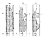
- FIGS. 2A, 2B, and 2C are diagrams illustrating control modes of the irradiation direction and irradiation range of the headlamp, respectively.
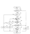
- FIG. 3 is a flowchart of processing executed by the ECU.
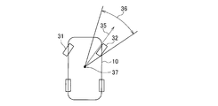
- FIG. 4 is a diagram exemplifying a traveling direction range of the vehicle determined according to the detected value of the steering angle.
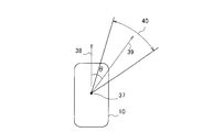
- FIG. 5 is a diagram exemplifying a vehicle traveling direction range determined according to the detected value of the yaw rate.
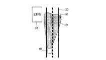
- FIG. 6 is a diagram illustrating the headlamp control according to the embodiment.
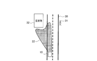
- FIG. 7 is a diagram showing headlamp control of a comparative example.
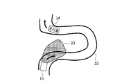
- FIG. 8 is a diagram illustrating the headlamp control according to the embodiment.
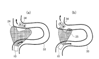
- FIGS. 9A and 9B are diagrams showing the headlamp control of the comparative example, respectively.
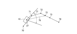
- FIG. 10 is a diagram illustrating an example of a vehicle traveling direction range determined according to a link shape interpolation point or the like.
- FIG. 11 is a diagram exemplifying a vehicle traveling direction range determined according to the detected white line.
- FIG. 1 the structure of the vehicle headlamp control system 1 which concerns on this embodiment is shown.
- the vehicle headlamp control system 1 is a system that is mounted on a vehicle and controls two headlamps (headlamps) 11 of the vehicle, and includes an image sensor 12, a headlamp drive unit 13, and an inter-vehicle communication unit 14. , Road information acquisition unit 15, ECU (Electronic Control Unit) 16 and the like.
- the image sensor 12 includes a camera unit and a detection unit.
- the camera unit repeatedly captures the front from the vehicle and sequentially outputs images of the imaging results to the detection unit.
- the detection unit performs a well-known detection process on the image output from the camera unit to detect a light source (an object that can be recognized as a vehicle by brightness, shape, color, etc. above a predetermined value) in the image. Then, the detected position coordinates of the light source (for example, the position coordinates of the left end, the right end, and the lower end of the light source in the image) are output to the ECU 16 as the position information of the light source.
- a light source an object that can be recognized as a vehicle by brightness, shape, color, etc. above a predetermined value
- the headlamp driving unit 13 is an actuator for controlling lighting, extinguishing, irradiation direction, irradiation range, and the like of the headlamp 11.
- the headlamp drive unit 13 changes the irradiation direction of the headlamp 11 in the left-right direction of the vehicle (that is, swivels) for each headlamp 11, and the headlamp 11 irradiation direction of the vehicle up and down. It has a leveling motor that changes the direction and a shutter that can be opened and closed to partially block the light of the headlamp 11.
- FIG. 2 illustrates a control mode of the irradiation direction and irradiation range of the headlamp 11 using a shutter.
- FIG. 2A shows the irradiation range 55 of the headlamp 11 when the vehicle 10 equipped with the vehicle headlamp control system 1 is in a high beam
- FIG. The irradiation range 56 of the headlamp 11 is shown
- FIG. 2C shows the irradiation range 57 of the headlamp 11 in the right light low beam (left light intermediate high beam).
- the headlamp driving unit 13 switches the irradiation mode among the high beam, the intermediate high beam, and the low beam as described above, and changes the irradiation direction of the headlamp 11 in the left-right direction of the vehicle using a swivel motor. controlling the irradiating direction and irradiating range.
- the inter-vehicle communication unit 14 is a wireless device for communicating with communication devices of other vehicles.
- the road information acquisition unit 15 acquires vehicle information such as the current position, direction, steering angle, and yaw rate of the vehicle from known sensors mounted on the vehicle, and information on the shape of the road on which the vehicle is currently traveling. The acquired information is output to the ECU 16.
- the road information acquisition unit 15 may acquire the road shape information from a navigation device mounted on the vehicle.
- the road information acquisition part 15 requests
- the link on which the vehicle is currently traveling is identified, the shape information of the identified link (position information of nodes and shape interpolation points) is read from the map data, and the read shape information is used as road information as road information. and it outputs the acquisition unit 15.
- the road information acquisition unit 15 may acquire road shape information using a known white line detection method.
- the road information acquisition unit 15 performs a known white line detection process on the image captured by the camera unit of the image sensor 13, thereby acquiring the shape of the white line at both ends of the road on which the host vehicle is traveling. Then, the shape of the road ahead of the vehicle is specified based on the acquired shape of the white line.
- the ECU 16 is an electronic control device provided with a microcomputer and the like, and executes various processes for controlling the headlamp 11 by executing a program recorded in the ECU 16 in advance.
- FIG. 3 shows a flowchart of processing executed by the ECU 16 while the vehicle 10 is traveling.
- the ECU 16 first determines in step 105 whether or not an ADB (adaptive driving beam) operation is possible. Whether or not the ADB operation can be performed is enabled when the user performs an ADB operation on operation switch (not shown), and cannot be performed when the ADB operation is turned off.
- ADB adaptive driving beam
- step 160 the headlamp driving unit 13 is controlled to bring the headlamp 11 into a low beam state, and the irradiation direction of the headlamp 11 with respect to the vehicle left-right direction is set to the front of the vehicle (the vehicle body Fix in the direction facing Alternatively, if the AFS (adaptive front light system) function is valid, the AFS operation is performed. Regardless of whether or not the ADB operation is possible, the driver switches the low beam to the high beam or switches the high beam to the low beam according to the operation of a predetermined beam switching switch. After step 160, the process returns to step 105.
- the headlamp driving unit 13 is controlled to bring the headlamp 11 into a low beam state, and the irradiation direction of the headlamp 11 with respect to the vehicle left-right direction is set to the front of the vehicle (the vehicle body Fix in the direction facing Alternatively, if the AFS (adaptive front light system) function is valid, the AFS operation is performed. Regardless of whether or not the ADB operation is possible, the driver switches the low beam to the
- step 110 is an acquisition unit that acquires the light source position information, and whether or not the light source position information is output from the detection unit of the image sensor 12. Alternatively, it is determined whether or not the image sensor 12 has detected a light source based on high beam switchable information or the like. If it is determined that the light source is not detected, the process proceeds to step 150, which is a control means for controlling the headlamp, and the headlamp driving unit 12 is controlled to switch the headlamp 11 to a high beam.
- step 120 is a determination means for determining based on the position information of the light source.
- the position information output from the detection unit of the image sensor 12 is acquired, and it is determined whether or not the light source is within the traveling direction range of the vehicle 10 based on the acquired position information.
- the traveling direction range of the vehicle 10 is specified according to the detected value of one or both of the vehicle speed, the steering angle, and the yaw rate of the vehicle 10 acquired by the road information acquisition unit 15.
- the turning radius is obtained from the vehicle speed and the steering angle, and the traveling direction 35 of the vehicle 10 is identified from the turning radius.
- a predetermined range in the left-right direction with the orientation 35 as the center direction for example, a range 36 from the center direction to 10 ° to the left and right.
- the center 37 of the angle setting is the center position of the vehicle 10).
- R (1 + A ⁇ V 2 ) (L / ⁇ ( ⁇ / 180 °))
- a method of calculating the turning radius R is employed by substituting the vehicle speed V and the steering angle ⁇ (more specifically, the steering angle of the front wheel, which is the steering wheel) into the equation.
- A is the stability factor of the vehicle
- L is the wheelbase of the vehicle, and both are parameters predetermined for each vehicle.
- the method of specifying the traveling direction 35 of the vehicle 10 from the turning radius R is as follows. The angle of the row direction 35 with respect to the front of the vehicle is ⁇ .
- the vehicle travel time is a time required for the vehicle to travel a predetermined distance (for example, 30 meters or 100 meters), and a result obtained by dividing the predetermined distance by the vehicle speed V is employed.
- the clockwise angle ⁇ from the vehicle body direction 38 of the current vehicle 10 increases as the yaw rate of right rotation increases.
- the center direction 39 is set, and a predetermined range in the left-right direction centered on the set center direction 39 (for example, a range 40 from the center direction 39 to 10 ° to the left and right.
- the angle setting center 37 is the vehicle 10 Is a traveling direction range of the vehicle 10.
- Whether or not the light source is in the specified traveling direction range is determined based on the position information of the light source acquired from the image sensor 12. Specifically, it calculates which direction the position coordinates included in the position information (that is, the position coordinates in the captured image of the light source) correspond to when viewed from the vehicle 10, and the calculated direction is the progress. It is determined whether it is included in the direction range.
- step 130 is a control means for controlling the headlamp, and the irradiation position is calculated. Specifically, using the acquired position coordinates of the light source and the correspondence table, the direction of the light source viewed from the vehicle 10 is calculated, and the light source is the center of the irradiation range of the headlamp 11 in the left-right direction. The irradiation direction of the headlamp 11 (the direction of the optical axis of the vehicle 10 in the left-right direction) that is located at is determined, and the determined irradiation direction is set as the irradiation position.
- step 135 it is determined whether or not the calculated irradiation position is within the ADB operating range.
- the ADB operating range is a range in which the direction of the optical axis of the headlamp 11 can be changed by the control of the headlamp driving unit 13, and indicates the ADB operating range in accordance with the performance of the headlamp 11 and the headlamp driving unit 13 in advance.
- ADB operating range data is recorded in the storage medium of the ECU 16.
- step 160 is a control means for controlling the headlamp, and performs the operation as already described. Do. If it is determined that the irradiation position is within the ADB operating range, the process proceeds to step 140 which is a control means for controlling the headlamp.
- step 140 a tracking swivel is realized by controlling the irradiation direction of the headlamp 11 to follow the direction of the light source. That is, the swivel motor of the headlamp driving unit 13 is controlled so that the irradiation position calculated in step 130 is realized in the headlamp 11. Further, in this step 140, ADB light distribution is realized. That is, since the light source may be a headlamp of another vehicle, the headlamp 11 is changed to an intermediate high beam or a low beam according to the position of the light source so that the light from the headlamp 11 does not directly hit the light source. switches. After step 140, the process returns to step 105.
- step 120 determines whether there is no light source in the traveling direction range of the vehicle 10. If it is determined in step 120 that there is no light source in the traveling direction range of the vehicle 10, the process proceeds to step 145, and it is determined whether or not the light source is a light of another vehicle. This determination is performed as follows, for example.
- the ECU 16 transmits a polling signal to the surroundings of the vehicle 10 using the inter-vehicle communication unit 14. If the light source is a light of another vehicle and the other vehicle has a vehicle-to-vehicle communication device, the vehicle-to-vehicle communication device of the other vehicle receives the polling signal and receives this.
- the current position coordinates for example, latitude and longitude
- the current position coordinates are transmitted to the vehicle-to-vehicle communication unit 14 that is the transmission source.
- the inter-vehicle communication unit 14 outputs the received current position coordinates of the other vehicle to the ECU 16.
- the ECU 16 compares the current position coordinates and direction of the own vehicle acquired from the road information acquisition unit 15 with the position coordinates of the other vehicle acquired from the road information acquisition unit 15, so that The direction of the vehicle is specified, and if the direction of the specified other vehicle and the direction of the light source (irradiation position) specified in step 130 coincide with each other within a predetermined error range, or other vehicle travel information (for example, a preceding vehicle) If the vehicle distance information, vehicle approach information, etc.) are received, it is determined that the light source is a light of another vehicle, and if it does not match, it is determined that it is not a light of another vehicle.
- step 150 control the headlamp driving unit 13 so as to obtain a high beam, and the irradiation direction of the headlamp 11 with respect to the left-right direction of the vehicle is set to the vehicle 10. Is changed so that the irradiation direction of the headlamp 11 is directed to the traveling direction of the vehicle 10 according to the steering angle and the vehicle speed. This irradiation direction control is performed regardless of the detected position of the light source. Or the irradiation direction of the headlamp 11 regarding the vehicle left-right direction is fixed to the front of the vehicle (the direction in which the vehicle body is facing). After step 150, the process returns to step 105.
- step 155 is a control means for controlling the headlamp, and the headlamp drive unit 13 is controlled so as to obtain a low beam, and the vehicle left-right direction is determined.
- the irradiation direction of the headlamp 11 is changed according to the steering angle of the vehicle 10 and the vehicle speed so that the irradiation direction of the headlamp 11 is directed in the traveling direction of the vehicle 10. This irradiation direction control is performed regardless of the detected position of the light source.
- the irradiation direction of the headlamp 11 in the left-right direction of the vehicle is fixed to the front of the vehicle (the direction in which the vehicle body is facing).
- the position information of the light source is acquired from the image sensor 12 (step 110), and whether or not the light source is within the traveling direction range of the host vehicle 10 determined according to the detected value of the steering angle or yaw rate of the host vehicle 10. Is determined based on the position information of the light source (step 120), and based on the positive determination result, control is performed to follow the irradiation direction of the headlamp 11 in the direction of the light source ( Steps 130 to 140) If the determination result is negative, the headlamp 11 is controlled regardless of the position of the light source.
- the traveling direction of the vehicle is determined according to the detected value of the steering angle or yaw rate even if the reflector 32 outside the road 30 is detected as the light source. If it is determined that it is not within the range, the irradiation direction of the headlamp 11 does not follow the reflecting object 32, so the irradiation range 21 of the headlamp 11 becomes a straight direction as usual, and as a result, a pedestrian 21 is located beside the road 30. You can illuminate the pedestrian if you are.
- the rudder of the vehicle 10 is detected. If it is determined that the vehicle 34 is not within the traveling direction range of the vehicle 10 determined according to the detected value of the corner or yaw rate, the irradiation direction of the headlamp 11 does not follow the vehicle 34, and therefore the irradiation range 23 of the headlamp 11 is As usual, the direction follows the steering, so that the road ahead can be illuminated.
- the light source is within the irradiation range of the headlamp. There is a possibility of entering. Therefore, if the low beam and the high beam are selectively used according to whether or not the light source is a light of another vehicle, the possibility of illuminating the vehicle with the high beam decreases.
- ECU16 acquires the positional information output from the detection part of the image sensor 12 by step 120, and whether the said light source exists in the advancing direction range of the vehicle 10 based on the acquired positional information. If the determination result is affirmative, the process proceeds to step 130. If the determination result is negative, the process proceeds to step 135, which is the same as in the first embodiment.
- the traveling direction range of the vehicle 10 is different from that of the first embodiment.
- the traveling direction range is specified according to the detected value of either one or both of the rudder angle and the yaw rate of the vehicle 10 acquired by the road information acquisition unit 15, but in this embodiment, The road information acquisition unit 15 determines based on the shape information of the currently traveling link acquired from the navigation device, or based on the shape information of the currently traveling road identified by the white line detection by the road information acquisition unit 15 decide.
- a predetermined point 75 (for example, the center) is set with the center point 76 as a center direction and a direction 76 from the center 37 of the host vehicle 10 to the reference point 75 as a center direction.
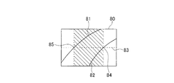
- the left and right ends 81 and 82 of the road identified in the captured image 80 by the white line detection are shown in FIG.
- the points 84 and 85 where the virtual center line 83 at the center in the vertical direction of the photographed image 80 and the white lines 81 and 82 intersect are specified, and specified from the direction corresponding to the specified point 85 A range up to a direction corresponding to the point 84 (referred to as a hatched range in FIG. 11) is set as a traveling direction range of the vehicle 10.
Abstract
Description
以下、本発明の第1実施形態について説明する。図1に、本実施形態に係る車両前照灯制御システム1の構成を示す。 (First embodiment)
The first embodiment of the present invention will be described below. In FIG. 1, the structure of the vehicle
R=(1+A×V2)(L/δ(π/180°))
という式に車速Vおよび舵角δ(より具体的には操舵輪である前輪の舵角)を代入することで、旋回半径Rを算出する方法を採用する。ここで、Aは車両のスタビリティーファクタであり、Lは車両のホイールベースであり、いずれも車両毎にあらかじめ決められたパラメータである。また、旋回半径Rから車両10の進行方向35を特定する方法は、車両の前方に対する行方向35の角度をβとすると、
β=α/2={360°×V×t/(2πR)}/2
という式に車速V、旋回半径R、車両走行時間tを代入することで、角度βを求める方法を採用する。ここで、車両走行時間は、車両が所定距離(例えば30メートル、100メートル)を走行するためにかかる時間であり、所定距離を車速Vで除算した結果を採用する。 As a method of obtaining the turning radius from the vehicle speed and the rudder angle,
R = (1 + A × V 2 ) (L / δ (π / 180 °))
A method of calculating the turning radius R is employed by substituting the vehicle speed V and the steering angle δ (more specifically, the steering angle of the front wheel, which is the steering wheel) into the equation. Here, A is the stability factor of the vehicle, L is the wheelbase of the vehicle, and both are parameters predetermined for each vehicle. Further, the method of specifying the traveling
β = α / 2 = {360 ° × V × t / (2πR)} / 2
A method of obtaining the angle β by substituting the vehicle speed V, the turning radius R, and the vehicle travel time t into the equation is adopted. Here, the vehicle travel time is a time required for the vehicle to travel a predetermined distance (for example, 30 meters or 100 meters), and a result obtained by dividing the predetermined distance by the vehicle speed V is employed.
次に、本発明の第2実施形態について説明する。本実施形態が第2実施形態と異なるのは、図3のステップ120における処理内容である。以下、その処理内容について説明する。
なお、第1実施形態と同一の構成要件には同一の符号を付し、説明を省略する。 (Second Embodiment)
Next, a second embodiment of the present invention will be described. This embodiment is different from the second embodiment in the processing content in
In addition, the same code | symbol is attached | subjected to the same component as 1st Embodiment, and description is abbreviate | omitted.
11 ヘッドランプ
12 画像センサ
13 ヘッドランプ駆動部
14 車車間通信部
15 道路情報取得部
16 ECU DESCRIPTION OF
Claims (4)
- 車両の周囲を撮影し、撮影した画像に基づいて光源を検出し、検出した光源の位置情報を出力する画像センサ(12)から、前記光源の位置情報を取得する取得手段(110)と、
前記車両の所定の進行方向範囲内に前記光源があるか否かを、前記取得手段(110)によって取得された前記光源の位置情報に基づいて判定する判定手段(120)と、
前記判定手段(120)の判定結果が肯定的であることに基づいて、前記光源の方向に前記前照灯の照射方向を追従させる制御を行い、前記判定手段(120)の判定結果が否定的であることに基づいて、前記光源の位置と無関係に前記前照灯を制御することを特徴とする制御手段(130~160)と、を備えた車両前照灯制御装置。 An acquisition means (110) for capturing the position information of the light source from an image sensor (12) that captures the periphery of the vehicle, detects a light source based on the captured image, and outputs position information of the detected light source;
Determining means (120) for determining whether or not the light source is within a predetermined traveling direction range of the vehicle based on positional information of the light source acquired by the acquiring means (110);
Based on the determination result of the determination means (120) being affirmative, control is performed to make the direction of irradiation of the headlamp follow the direction of the light source, and the determination result of the determination means (120) is negative. And a control means (130-160) for controlling the headlamp irrespective of the position of the light source. - 前記判定手段は、前記進行方向範囲を、前記車両の舵角またはヨーレートに基づいて決定することを特徴とする請求項1に記載の車両前照灯制御装置。 2. The vehicle headlamp control device according to claim 1, wherein the determination unit determines the traveling direction range based on a steering angle or a yaw rate of the vehicle.
- 前記判定手段は、前記進行方向範囲を、前記車両が現在走行中の道路の形状情報に基づいて決定することを特徴とする請求項1に記載の車両前照灯制御装置。 2. The vehicle headlamp control device according to claim 1, wherein the determination unit determines the range in the traveling direction based on shape information of a road on which the vehicle is currently traveling.
- 前記制御手段(130~160)は、前記判定手段(120)の判定結果が否定的である場合、前記光源が他の車両のライトであるか否かを判定し、他の車両のライトであると判定すれば前記前照灯をロービームに制御し、他の車両のライトでないと判定すれば前記前照灯をハイビームに制御することを特徴とする請求項1ないし3のいずれか1つに記載の車両前照灯制御装置。 The control means (130 to 160) determines whether the light source is a light of another vehicle when the determination result of the determination means (120) is negative, and is a light of another vehicle. The headlamp is controlled to a low beam if it is determined that the headlight is not a light of another vehicle, and the headlamp is controlled to a high beam if it is determined that the headlight is not a light of another vehicle. of the vehicle headlamp control system.
Priority Applications (2)
| Application Number | Priority Date | Filing Date | Title |
|---|---|---|---|
| DE201211003611 DE112012003611T5 (en) | 2011-08-29 | 2012-07-18 | Vehicle headlamp control system |
| US14/241,504 US20140246975A1 (en) | 2011-08-29 | 2012-07-18 | Vehicle headlamp control system |
Applications Claiming Priority (2)
| Application Number | Priority Date | Filing Date | Title |
|---|---|---|---|
| JP2011-186165 | 2011-08-29 | ||
| JP2011186165A JP2013047058A (en) | 2011-08-29 | 2011-08-29 | Vehicle headlight control device |
Publications (1)
| Publication Number | Publication Date |
|---|---|
| WO2013031404A1 true WO2013031404A1 (en) | 2013-03-07 |
Family
ID=47755911
Family Applications (1)
| Application Number | Title | Priority Date | Filing Date |
|---|---|---|---|
| PCT/JP2012/068199 WO2013031404A1 (en) | 2011-08-29 | 2012-07-18 | Vehicle headlights control device |
Country Status (4)
| Country | Link |
|---|---|
| US (1) | US20140246975A1 (en) |
| JP (1) | JP2013047058A (en) |
| DE (1) | DE112012003611T5 (en) |
| WO (1) | WO2013031404A1 (en) |
Families Citing this family (8)
| Publication number | Priority date | Publication date | Assignee | Title |
|---|---|---|---|---|
| US9694737B2 (en) * | 2014-06-16 | 2017-07-04 | Nissan North America, Inc. | Vehicle headlight control system and method |
| DE102014219323A1 (en) * | 2014-09-24 | 2016-03-24 | Continental Teves Ag & Co. Ohg | Method for controlling the light distribution of vehicle headlights and vehicle |
| KR20180071663A (en) * | 2016-12-20 | 2018-06-28 | 현대자동차주식회사 | Vehicle and method for controlling thereof |
| DE102017121662B4 (en) * | 2017-09-19 | 2020-01-02 | Varroc Lighting Systems, s.r.o. | Arrangement and method for producing asymmetrical, glare-free high beam |
| JP7110650B2 (en) * | 2018-03-22 | 2022-08-02 | マツダ株式会社 | Vehicle headlight switch device |
| US20200247309A1 (en) * | 2019-02-06 | 2020-08-06 | Ford Global Technologies, Llc | Vehicle lamp-cleaning system |
| US11325523B2 (en) * | 2019-04-02 | 2022-05-10 | Pony Ai Inc. | Lighting element control for an autonomous vehicle |
| JP2020177452A (en) * | 2019-04-18 | 2020-10-29 | 矢崎エナジーシステム株式会社 | On-vehicle apparatus and on-vehicle system |
Citations (3)
| Publication number | Priority date | Publication date | Assignee | Title |
|---|---|---|---|---|
| JP2009029227A (en) * | 2007-07-26 | 2009-02-12 | Omron Corp | Lighting control device, method and program |
| JP2010132053A (en) * | 2008-12-03 | 2010-06-17 | Koito Mfg Co Ltd | Headlight control device |
| JP2011031807A (en) * | 2009-08-04 | 2011-02-17 | Koito Mfg Co Ltd | Light distribution control system for vehicular headlamp |
Family Cites Families (5)
| Publication number | Priority date | Publication date | Assignee | Title |
|---|---|---|---|---|
| JP2008110686A (en) * | 2006-10-31 | 2008-05-15 | Denso Corp | Headlamp swivel controller |
| JP5301383B2 (en) * | 2009-07-29 | 2013-09-25 | 株式会社小糸製作所 | Vehicle headlamp device |
| JP5293893B2 (en) * | 2010-11-24 | 2013-09-18 | トヨタ自動車株式会社 | VEHICLE LIGHTING DEVICE AND VEHICLE HEADLAMP CONTROL METHOD |
| JP2013028274A (en) * | 2011-07-28 | 2013-02-07 | Denso Corp | Headlight light control device |
| JP2013043623A (en) * | 2011-08-26 | 2013-03-04 | Stanley Electric Co Ltd | Lighting control device of vehicle headlamp, and vehicle headlamp system |
-
2011
- 2011-08-29 JP JP2011186165A patent/JP2013047058A/en active Pending
-
2012
- 2012-07-18 WO PCT/JP2012/068199 patent/WO2013031404A1/en active Application Filing
- 2012-07-18 DE DE201211003611 patent/DE112012003611T5/en not_active Withdrawn
- 2012-07-18 US US14/241,504 patent/US20140246975A1/en not_active Abandoned
Patent Citations (3)
| Publication number | Priority date | Publication date | Assignee | Title |
|---|---|---|---|---|
| JP2009029227A (en) * | 2007-07-26 | 2009-02-12 | Omron Corp | Lighting control device, method and program |
| JP2010132053A (en) * | 2008-12-03 | 2010-06-17 | Koito Mfg Co Ltd | Headlight control device |
| JP2011031807A (en) * | 2009-08-04 | 2011-02-17 | Koito Mfg Co Ltd | Light distribution control system for vehicular headlamp |
Also Published As
| Publication number | Publication date |
|---|---|
| DE112012003611T5 (en) | 2014-06-12 |
| US20140246975A1 (en) | 2014-09-04 |
| JP2013047058A (en) | 2013-03-07 |
Similar Documents
| Publication | Publication Date | Title |
|---|---|---|
| WO2013031404A1 (en) | Vehicle headlights control device | |
| US8019512B2 (en) | System for adjusting direction of optical axis of headlight | |
| JP4466604B2 (en) | Vehicle headlamp device | |
| US8892301B2 (en) | Apparatus and method for controlling head lamp of vehicle | |
| US9193297B2 (en) | Vehicle light distribution control device and vehicle light distribution control method | |
| US9436881B2 (en) | Apparatus for predicting turns of a vehicle | |
| US8866387B2 (en) | Vehicular headlight apparatus | |
| US8757853B2 (en) | Method for controlling a vehicle headlamp | |
| JP2011037342A (en) | Vehicular headlight system | |
| KR101934750B1 (en) | Lighting System for Vehicle and Control Method Thereof | |
| CN111824004A (en) | Light distribution control device for vehicle | |
| KR20130129647A (en) | An automobile and method for controling thereof | |
| JP2011037343A (en) | Light distribution control system for vehicular headlight | |
| JP2011037414A (en) | Headlamp system for vehicle | |
| JP2009184640A (en) | Headlight device of vehicle | |
| JP2006096158A (en) | Light distribution controlling device for vehicle headlight | |
| JP4737108B2 (en) | Headlight control device | |
| JP5652374B2 (en) | Vehicle headlamp control device | |
| JP2020011539A (en) | Control apparatus for vehicular headlight, control method for vehicular headlight, and vehicular headlight system | |
| JP4144411B2 (en) | Vehicle lighting | |
| KR101335630B1 (en) | Apparatus and method for controlling lamp of vehicle | |
| JP2012197037A (en) | Irradiation direction control device and irradiation direction control system | |
| JPH07186818A (en) | Automatic light distribution device for vehicle head lamp | |
| JP2004330906A (en) | Headlamp for vehicle | |
| JP2012218587A (en) | Irradiation direction control device and irradiation direction control system |
Legal Events
| Date | Code | Title | Description |
|---|---|---|---|
| 121 | Ep: the epo has been informed by wipo that ep was designated in this application |
Ref document number: 12828419 Country of ref document: EP Kind code of ref document: A1 |
|
| WWE | Wipo information: entry into national phase |
Ref document number: 112012003611 Country of ref document: DE Ref document number: 1120120036115 Country of ref document: DE |
|
| WWE | Wipo information: entry into national phase |
Ref document number: 14241504 Country of ref document: US |
|
| 122 | Ep: pct application non-entry in european phase |
Ref document number: 12828419 Country of ref document: EP Kind code of ref document: A1 |