WO2013027628A1 - Dispositif de traitement d'informations, procédé de traitement d'informations et programme - Google Patents
Dispositif de traitement d'informations, procédé de traitement d'informations et programme Download PDFInfo
- Publication number
- WO2013027628A1 WO2013027628A1 PCT/JP2012/070677 JP2012070677W WO2013027628A1 WO 2013027628 A1 WO2013027628 A1 WO 2013027628A1 JP 2012070677 W JP2012070677 W JP 2012070677W WO 2013027628 A1 WO2013027628 A1 WO 2013027628A1
- Authority
- WO
- WIPO (PCT)
- Prior art keywords
- plane
- information processing
- unit
- processing apparatus
- image
- Prior art date
Links
Images


Classifications
-
- G—PHYSICS
- G06—COMPUTING; CALCULATING OR COUNTING
- G06T—IMAGE DATA PROCESSING OR GENERATION, IN GENERAL
- G06T11/00—2D [Two Dimensional] image generation
- G06T11/60—Editing figures and text; Combining figures or text
-
- G—PHYSICS
- G01—MEASURING; TESTING
- G01C—MEASURING DISTANCES, LEVELS OR BEARINGS; SURVEYING; NAVIGATION; GYROSCOPIC INSTRUMENTS; PHOTOGRAMMETRY OR VIDEOGRAMMETRY
- G01C21/00—Navigation; Navigational instruments not provided for in groups G01C1/00 - G01C19/00
- G01C21/26—Navigation; Navigational instruments not provided for in groups G01C1/00 - G01C19/00 specially adapted for navigation in a road network
- G01C21/34—Route searching; Route guidance
- G01C21/36—Input/output arrangements for on-board computers
- G01C21/3626—Details of the output of route guidance instructions
- G01C21/3647—Guidance involving output of stored or live camera images or video streams
-
- G—PHYSICS
- G06—COMPUTING; CALCULATING OR COUNTING
- G06F—ELECTRIC DIGITAL DATA PROCESSING
- G06F3/00—Input arrangements for transferring data to be processed into a form capable of being handled by the computer; Output arrangements for transferring data from processing unit to output unit, e.g. interface arrangements
- G06F3/01—Input arrangements or combined input and output arrangements for interaction between user and computer
- G06F3/03—Arrangements for converting the position or the displacement of a member into a coded form
- G06F3/0304—Detection arrangements using opto-electronic means
-
- G—PHYSICS
- G06—COMPUTING; CALCULATING OR COUNTING
- G06F—ELECTRIC DIGITAL DATA PROCESSING
- G06F3/00—Input arrangements for transferring data to be processed into a form capable of being handled by the computer; Output arrangements for transferring data from processing unit to output unit, e.g. interface arrangements
- G06F3/01—Input arrangements or combined input and output arrangements for interaction between user and computer
- G06F3/03—Arrangements for converting the position or the displacement of a member into a coded form
- G06F3/033—Pointing devices displaced or positioned by the user, e.g. mice, trackballs, pens or joysticks; Accessories therefor
- G06F3/0346—Pointing devices displaced or positioned by the user, e.g. mice, trackballs, pens or joysticks; Accessories therefor with detection of the device orientation or free movement in a 3D space, e.g. 3D mice, 6-DOF [six degrees of freedom] pointers using gyroscopes, accelerometers or tilt-sensors
-
- G—PHYSICS
- G06—COMPUTING; CALCULATING OR COUNTING
- G06T—IMAGE DATA PROCESSING OR GENERATION, IN GENERAL
- G06T19/00—Manipulating 3D models or images for computer graphics
- G06T19/006—Mixed reality
-
- G—PHYSICS
- G06—COMPUTING; CALCULATING OR COUNTING
- G06T—IMAGE DATA PROCESSING OR GENERATION, IN GENERAL
- G06T7/00—Image analysis
- G06T7/70—Determining position or orientation of objects or cameras
Definitions
- the present disclosure relates to an information processing apparatus, an information processing method, and a program.
- AR augmented reality
- Information presented to the user in AR technology is also called annotation, and can be visualized using various forms of virtual objects such as text, icons or animations.
- the placement of annotations in the AR space is usually performed based on recognition of the three-dimensional structure of the real space shown in the image.
- SfM Structure from Motion
- SLAM Simultaneous Localization And Mapping
- Patent Document 1 discloses a technique for recognizing a three-dimensional position of a feature point selected at the time of initialization in the SLAM method using the SfM method.
- the position and orientation of an object (or the real space itself) existing in the real space with respect to the imaging plane of the image can be recognized.
- a technique based on image recognition such as the SfM method may not achieve sufficient recognition accuracy.
- the recognition accuracy of the SfM method deteriorates for a two-dimensional plane (for example, a horizontal plane such as the ground, a floor or a ceiling, or a vertical plane such as a wall of a building) in which an image change due to parallax hardly occurs. easy.
- a two-dimensional plane for example, a horizontal plane such as the ground, a floor or a ceiling, or a vertical plane such as a wall of a building
- improvement in the accuracy of recognition of the plane pose is particularly strongly required in the AR technology.
- a data acquisition unit that acquires sensor data indicating a direction of gravity applied to an imaging device that captures an image that reflects a real space, and a relative plane of the real space with respect to the image based on the sensor data Conversion between a determination unit that determines a specific posture and a three-dimensional position of a given point on the plane and a corresponding two-dimensional position in the image, using the posture determined by the determination unit And an information processing apparatus including the conversion unit.
- the sensor data indicating the direction of gravity applied to the imaging device that captures the image that reflects the real space is acquired, and based on the sensor data, Determining the relative pose of the real space plane relative to the image and the transformation between the 3D position of a given point on the plane and the corresponding 2D position in the image was determined And performing using the posture.
- the computer that controls the information processing device is configured to acquire a sensor data indicating a direction of gravity applied to the imaging device that captures an image that reflects a real space, and based on the sensor data.
- FIG. 6 is a flowchart illustrating a third example of the flow of plane determination processing by the determination unit illustrated in FIG. 4.
- 5 is a flowchart illustrating an example of a flow of SLAM calculation processing by a SLAM calculation unit illustrated in FIG. 4.
- 15 is a flowchart illustrating an example of a flow of initialization processing included in the SLAM calculation processing illustrated in FIG. 14. It is explanatory drawing for demonstrating the feature point set on a real object. It is explanatory drawing for demonstrating addition of a feature point. It is explanatory drawing for demonstrating an example of a prediction model. It is explanatory drawing for demonstrating an example of a structure of feature data.
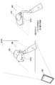
- FIG. 1 is a first explanatory diagram for explaining an overview of an information processing apparatus 100 according to an embodiment.
- the information processing apparatus 100 includes an imaging unit 102 and a display unit 110 that are directed to the real space 10.
- a road 12 a wall surface 13 a of a building, and a wall surface 13 b of a building exist in the real space 10.
- the information processing apparatus 100 includes an AR application for navigation, and superimposes annotations A11 and A12 for navigation on an image Im01 captured by the imaging unit 102.
- the annotation A1 is an annotation in the shape of an arrow that guides the route to the user Ua, and is arranged on a horizontal plane along the road 12 shown in the image Im01.
- the annotation A12 is an annotation that conveys some guidance message to the user Ua, and is arranged on the vertical plane along the wall surface 13a shown in the image Im01.
- FIG. 1 shows a mobile terminal as an example of the information processing apparatus 100.
- the information processing apparatus 100 is not limited to such an example.
- the information processing apparatus 100 may be, for example, a PC (Personal Computer), a PDA (Personal Digital Assistant), a smartphone, a game terminal, a PND (Portable Navigation Device), a content player, or a digital home appliance.
- FIG. 2 is a second explanatory diagram for explaining an overview of the information processing apparatus 100.
- the information processing device 100 is a server device connected to the terminal device 20 that the user Ua has.
- the terminal device 20 includes an imaging unit 22 and a display unit 24 that are directed to the real space 10.
- a table 14 exists in the real space 10.
- the information processing apparatus 100 superimposes the annotation A2 on the image Im02 captured by the terminal device 20.
- the annotation A2 is an annotation in the shape of a virtual car running on the table 14, and is arranged on a horizontal plane along the surface of the table 14 shown in the image Im02.
- FIG. 3 is a block diagram illustrating an example of a hardware configuration of the information processing apparatus 100 according to the first embodiment.
- the information processing apparatus 100 includes an imaging unit 102, a sensor unit 104, an input unit 106, a storage unit 108, a display unit 110, a communication unit 112, a bus 116, and a control unit 118.
- Imaging unit 102 is a camera module that captures an image.
- the imaging unit 102 images a real space using an imaging element such as a charge coupled device (CCD) or a complementary metal oxide semiconductor (CMOS), and generates a captured image.
- the captured image generated by the imaging unit 102 is an input image for image processing by the control unit 118.
- the imaging unit 102 is not necessarily a part of the information processing apparatus 100.
- an imaging apparatus connected to the information processing apparatus 100 by wire or wireless may be handled as the imaging unit 102.
- the sensor unit 104 may include various sensors that are used to assist the information processing apparatus 100 in determining the plane posture.
- the sensor unit 104 includes a triaxial acceleration sensor that measures gravitational acceleration applied to the imaging unit 102.
- the three-axis acceleration sensor measures the gravitational acceleration applied to the imaging unit 102 and generates sensor data (acceleration data) that three-dimensionally represents the magnitude and direction of the gravitational acceleration.
- the sensor unit 104 may include a geomagnetic sensor that measures the direction of geomagnetism.
- the geomagnetic sensor generates sensor data (geomagnetic data) indicating the direction of geomagnetism in the coordinate system of the imaging unit 102.
- the sensor unit 104 may include a positioning sensor (for example, a GPS (Global Positioning System) sensor) that measures the position of the information processing apparatus 100.
- the positioning sensor generates sensor data (positioning data) representing the latitude and longitude of the information processing apparatus 100 in real space. Note that the sensor unit 104 is not necessarily a part of the information processing apparatus 100.
- the input unit 106 is an input device used by a user to operate the information processing apparatus 100 or input information to the information processing apparatus 100.
- the input unit 106 may include, for example, a touch sensor that detects a user's touch on the screen of the display unit 110.
- the input unit 106 may include a pointing device such as a mouse or a touchpad.
- the input unit 106 may include other types of input devices such as a keyboard, keypad, buttons, or switches.
- the storage unit 108 is configured by a storage medium such as a semiconductor memory or a hard disk, and stores a program and data for processing by the information processing apparatus 100.
- the data stored by the storage unit 108 may include, for example, captured image data, sensor data, and data in various databases (DB) described later.
- DB databases
- some of the programs and data described in this specification may be acquired from an external data source (for example, a data server, a network storage, or an external memory) without being stored in the storage unit 108. .
- the display unit 110 is a display module including a display such as an LCD (Liquid Crystal Display), an OLED (Organic light-Emitting Diode), or a CRT (Cathode Ray Tube).
- the display unit 110 is used, for example, to display an AR application image generated by the information processing apparatus 100.
- the display unit 110 is not necessarily a part of the information processing apparatus 100.
- a display device connected to the information processing device 100 by wire or wireless may be handled as the display unit 110.
- the communication unit 112 is a communication interface that mediates communication between the information processing apparatus 100 and other apparatuses.
- the communication unit 112 supports an arbitrary wireless communication protocol or wired communication protocol, and establishes a communication connection with another device.
- Bus The bus 116 connects the imaging unit 102, the sensor unit 104, the input unit 106, the storage unit 108, the display unit 110, the communication unit 112, and the control unit 118 to each other.
- the control unit 118 corresponds to a processor such as a CPU (Central Processing Unit) or a DSP (Digital Signal Processor).
- the control unit 118 operates various functions of the information processing apparatus 100 to be described later by executing a program stored in the storage unit 108 or another storage medium.
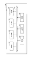
- [2-2. Functional configuration] 4 is a block diagram illustrating an example of a configuration of logical functions realized by the storage unit 108 and the control unit 118 of the information processing apparatus 100 illustrated in FIG.
- the information processing apparatus 100 includes an image acquisition unit 120, a data acquisition unit 125, a determination unit 130, a three-dimensional (3D) structure DB 135, a conversion unit 140, a SLAM calculation unit 145, an object DB 150, and an image recognition unit 156. , Annotation DB 160, display control unit 165, and user interface unit 170.
- the image acquisition unit 120 acquires a captured image generated by the imaging unit 102 as an input image.
- the input image acquired by the image acquisition unit 120 is an image showing a real space.
- the input image may be a still image or each frame constituting a moving image.
- the image acquisition unit 120 outputs the acquired input image to the SLAM calculation unit 145, the image recognition unit 156, and the display control unit 165.
- the data acquisition unit 125 acquires data used for plane determination processing by the determination unit 130.
- the data acquisition unit 125 acquires sensor data generated by the sensor unit 104 that may include at least one of acceleration data, geomagnetic data, and positioning data.
- the data acquisition unit 125 may acquire map data for the surrounding area of the position indicated by the positioning data from a database stored in advance by the information processing apparatus 100 or an external data server. Then, the data acquisition unit 125 outputs the acquired data to the determination unit 130.
- the determining unit 130 determines the relative posture of the plane of the real space with respect to the imaging surface of the input image based on the sensor data acquired by the data acquiring unit 125.
- the method for determining the attitude of the horizontal plane will be described in detail first, and then the determination of the attitude of the vertical plane and other planes will be described.
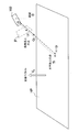
- FIG. 5 is an explanatory diagram for explaining the relationship among the imaging plane, the horizontal plane, and the direction of gravity.
- the horizontal plane HP may be a plane such as an existing ground, floor, or ceiling, or may be an imaginary plane.
- the horizontal plane HP is orthogonal to the direction of gravity.
- the attitude of the horizontal plane HP with respect to the imaging plane IP (or the attitude of the imaging plane IP with respect to the horizontal plane HP) can change depending on the attitude of the imaging unit 102. Therefore, determining unit 130, the gravity direction vector V G indicated by the sensor data described above, to determine the relative orientation of the horizontal plane HP with respect to the imaging plane IP.
- the determination unit 130 if the sensor data (3 axis accelerometer) 3-dimensional coordinate system and the three-dimensional coordinate system of the imaging surface (and depth) do not match, the gravity direction vector V G, coordinate Rotational transformation and scale transformation may be performed so that system differences are absorbed.
- FIG. 6 is an explanatory diagram for describing parameters related to the 3D structure of the horizontal plane.
- a normal vector V N representing the horizontal plane attitude in the coordinate system of the imaging unit 102 is shown.
- the size of the gravity direction vector V G is assumed to be normalized.
- the horizontal plane HP in this case can correspond to the ground or floor surface below the focal point of the imaging unit 102.
- the horizontal plane HP in this case can correspond to a ceiling surface above the focus of the imaging unit 102.
- the horizontal plane is obtained using the distance D from the origin to the horizontal plane HP.
- the distance D changes depending on the position of the horizontal plane in the real space. Further, when the distance D changes, the scale of the horizontal plane in the input image changes.
- FIG. 7 is a flowchart illustrating a first example of a plane determination process performed by the determination unit 130.
- the posture of the horizontal plane is determined.
- the data acquisition unit 125 acquires sensor data indicating the direction of gravity applied to the imaging unit 102 (step S1).
- the determination unit 130 determines the attitude of the horizontal plane (the normal vector V N described above) based on the sensor data acquired by the data acquisition unit 125 (step S2).
- the orientation of the horizontal plane may be determined depending on whether the imaging unit 102 is facing upward or downward.
- the horizontal plane can be determined using only acceleration data indicating the direction of gravity.
- the attitude of the vertical plane can be determined by using some restrictions, additional sensor data, or user input.
- the posture of a real space plane includes an elevation angle component and an azimuth angle component.
- the elevation angle (Elevation) is an angle in the vertical direction with respect to the horizontal plane, and usually takes a value within a range of ⁇ 90 ° to 90 ° (angle ⁇ of vector V 0 in FIG. 8).
- the azimuth is an angle in the east, west, south, and north directions with respect to some vertical plane, and usually takes a value within a range of 0 ° to 360 ° (angle ⁇ of the vector V 0 in FIG. 8).
- the elevation angle component can be determined by a method similar to the determination of the posture of the horizontal plane. Several approaches may exist to determine the remaining azimuth component.
- the determination unit 130 determines the attitude of the vertical plane based on the acceleration data and the predefined direction constraints.
- the predefined direction constraint may be, for example, a constraint that the imaging surface is directly facing the target vertical surface (the camera is set so that they are facing each other).
- the determination unit 130 is a unit vector that is orthogonal to the normal vector of the horizontal plane that is determined based on the direction of gravity, and that is closest to the optical axis of the camera (for example, a vector that faces the opposite direction of the optical axis) Can be determined as the normal vector of the vertical plane of interest.
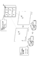
- the determination unit 130 determines the attitude of the vertical plane based on the acceleration data and the positioning data. More specifically, the determination unit 130 acquires map data about the area around the position of the information processing apparatus 100 indicated by the positioning data via the data acquisition unit 125 (upper left in FIG. 9). The map data acquired here indicates a positional relationship between the imaging unit 102 and one or more vertical planes located around the information processing apparatus 100. Further, the determination unit 130 calculates the azimuth of the optical axis of the imaging unit 102 based on the geomagnetic data (upper right in FIG. 9).
- the determination unit 130 specifies a vertical plane that enters the angle of view of the imaging unit 102 (that is, a vertical plane that appears in the input image) from one or more vertical planes in the map data.
- the vertical plane specified here may be a plane (such as a building wall surface) on which a line segment extending in the optical axis direction of the imaging unit 102 collides for the first time on the map from the position indicated by the positioning data (FIG. 9). under).
- the determination unit 130 acquires the orientation of the specified vertical plane in the real space coordinate system from the map data, and uses the geomagnetic direction indicated by the geomagnetic data to determine the orientation of the specified vertical plane in the coordinate system of the imaging unit 102. Convert to orientation.
- the determination unit 130 calculates a vector closest to the orientation of the vertical plane after conversion from among unit vectors orthogonal to the normal vector of the horizontal plane (in the coordinate system of the imaging unit 102). It can be determined as a line vector.
- the determination unit 130 uses the azimuth of the optical axis calculated based on the geomagnetic data, and instead of specifying on the map the vertical plane that appears in the input image, the determination unit 130 The surface may be specified by the user.
- a map MP is superimposed on an image Im03 on the screen of the display unit 110.
- the map MP indicates the position of the wall surface of the building or the like existing in the surrounding area of the position indicated by the positioning data.
- the user designates the vertical plane shown in the input image by an operation such as a touch on the map MP, for example.
- the determination unit 130 can recognize which vertical plane on the map is reflected in the input image.
- the determination unit 130 may recognize which vertical plane on the map appears in the input image by matching the image of a known building with the input image.
- FIG. 11 is a flowchart illustrating a second example of the flow of the plane determination process executed by the determination unit 130.
- the posture of the vertical plane is determined according to the second method described above.
- the data acquisition unit 125 acquires sensor data that can include acceleration data, positioning data, and geomagnetic data (step S1).
- the determination part 130 determines the normal vector of a horizontal surface based on the acceleration data which shows the direction of gravity (step S2).
- the determination unit 130 acquires map data of the surrounding area at the position indicated by the positioning data (step S4).
- the determination unit 130 specifies a vertical plane shown in the input image on the map using, for example, geomagnetic data (step S5).
- the determination unit 130 determines the normal vector of the specified vertical plane that is orthogonal to the normal vector of the horizontal plane determined in step S2 (step S6).
- the determination unit 130 determines the plane equation of the specified vertical plane using a provisional value that is defined in advance as a constant term of the plane equation (step S7).
- FIG. 12A is an explanatory diagram showing an example of a user interface for allowing the user to specify an arbitrary plane posture.
- a user interface UI1 having a spherical appearance is superimposed on an image Im04.
- the reference plane RP is a horizontal plane that passes through the center of the sphere of the user interface UI1.
- the determination unit 130 determines the posture of the reference plane RP according to the above-described method for determining the posture of the horizontal plane.
- the user interface UI1 is arranged in the AR space by the user interface unit 170 described later with reference to the orientation of the reference plane RP. By tracking the direction of gravity, the arrangement of the user interface UI1 is maintained in the AR space over a plurality of frames. As a result, the user interface UI1 is displayed as if it is fixed in the real space even if the angle of view changes.
- the user interface UI1 has a disk-like operation surface OD1 that passes through the center of the sphere.
- the operation surface OD1 may be disposed horizontally in the same manner as the reference surface RP.
- Two axes AX1 and AX2 associated with the operation surface OD1 are axes that are perpendicular to each other and parallel to the operation surface OD1.
- the axis AX3 is an axis perpendicular to the axes AX1 and AX2.
- the operation surface OD1 can be three-dimensionally rotated by the user. For example, when the user slides (drags) a finger horizontally on the screen, the operation surface OD1 rotates about the axis AX3.
- the operation surface OD1 rotates around the axis AX2. Through such an operation, the user rotates the operation surface OD1 three-dimensionally so that the arbitrary plane reflected in the input image and the operation surface OD1 are parallel to each other. And the determination part 130 determines the attitude
- the normal vector of the arbitrary plane has the same direction as the axis AX3 after the operation.
- the user interface for determining the orientation of an arbitrary plane is not limited to the example of FIG. 12A.
- the user interface may have a shape other than a spherical shape, and the operation surface may have a shape other than a disk.
- the operation surface OD1 may be rotatable in accordance with a different type of operation from the operation of sliding the finger (for example, tapping a predetermined button, pressing a cross key, etc.).
- a vertical plane may be used as a reference plane for arranging the user interface instead of the horizontal plane.
- FIG. 12B is an explanatory diagram showing another example of a user interface for allowing the user to specify the posture of an arbitrary plane.
- a user interface UI2 having the appearance of an animal character is superimposed on an image Im05.
- the user interface UI2 may be one of annotations for the AR application instead of a dedicated user interface for determining the orientation of the plane.
- the determination unit 130 determines the posture of the reference plane RP according to the above-described method for determining the posture of the horizontal plane. Then, the user interface UI2 is arranged in the AR space with reference to the orientation of the reference plane RP.
- the user interface UI2 has an operation surface OD2 arranged in parallel with the reference surface RP in the initial state.
- the operation surface OD2 has a character-like appearance.
- the user interface UI2 (character and its shadow) can be rotated three-dimensionally by the user. Through the operation, the user rotates the user interface UI2 three-dimensionally so that an arbitrary plane reflected in the input image and the operation surface OD2 are parallel to each other.
- the determination part 130 determines the attitude
- FIG. 13 is a flowchart illustrating a third example of the flow of the plane determination process executed by the determination unit 130.
- the posture of an arbitrary plane is determined using the above-described user interface.
- the data acquisition unit 125 acquires sensor data indicating the direction of gravity (step S1).
- the determination part 130 determines the attitude
- the user interface UI1 illustrated in FIG. 12A (or the user interface UI2 illustrated in FIG. 12B) is arranged in the AR space with reference to the orientation of the reference plane, and is displayed on the screen (step S8).
- the display of the user interface can be continued until, for example, a user input indicating the end of the operation is detected.
- the determination unit 130 determines a normal vector of an arbitrary plane from the attitude of the operated operation surface of the user interface, and further determines a plane equation of the arbitrary plane (step S9).
- the 3D structure DB 135 is a database that stores a 3D structure of real space imaged by the imaging unit 102.
- the 3D structure DB 135 stores, for example, constant terms and coefficients constituting the plane equation of the plane determined by the determination unit 130, that is, the position and orientation.
- the 3D structure DB 135 may store the position and orientation of the imaging unit 102 that are additionally recognized by the SLAM calculation unit 145 and can change with time.
- the 3D structure DB 135 may store the position and orientation of a real object that can be recognized by the image recognition unit 156.
- the display control unit 165 described later determines the placement of annotations in the AR space according to the position and orientation of a plane stored in the 3D structure DB 135 or the position and orientation of a real object.
- the conversion unit 140 performs conversion between the three-dimensional position of a given point on the plane and the two-dimensional position in the image corresponding to the three-dimensional position (that is, on the imaging surface). The determination is performed using the plane orientation determined by the determination unit 130.
- the calculation process for conversion between the three-dimensional position and the two-dimensional position by the conversion unit 140 may be performed according to a known pinhole camera model. The calculation process performed by the conversion unit 140 according to the pinhole camera model will be described with reference to FIG. 6 again, taking a horizontal plane as an example.
- Point U i is projected to point Q i in three-dimensional space using the inverse matrix A ⁇ 1 of camera internal parameter matrix A as follows:
- (f x , f y ) represents a scale change rate between the imaging surface and the real space.
- (C x , C y ) is the center position of the imaging surface.
- the scale r i in equation (4) is derived by the following equation.
- D may be a provisional value defined in advance.
- the three-dimensional position T i of the point is obtained using the posture V N and the position D of the horizontal plane HP.
- a method for obtaining the two-dimensional position U i on the imaging surface corresponding to the point is also derived according to a similar pinhole camera model. obtain.
- given points to be subjected to calculation processing by the conversion unit 140 include at least feature points selected at the time of initialization of the SLAM method described below.
- the point constituting the annotation for the AR application can also be a target of calculation processing by the conversion unit 140. Note that even when a vertical plane or an arbitrary plane is used instead of the horizontal plane, the coordinate conversion can be performed in the same manner as described here.
- the SLAM operation unit 145 dynamically recognizes the 3D structure of the real space reflected in the input image from the monocular camera and the position and orientation of the imaging unit 102 by performing an operation according to the SLAM method. To do.
- FIG. 14 is a flowchart showing an example of the flow of SLAM calculation processing by the SLAM calculation unit 145.
- the SLAM calculation unit 145 first executes an initialization process to initialize state variables (step S10).
- the state variable is a vector including, as elements, the position and orientation (rotation angle) of the camera, the moving speed and angular velocity of the camera, and the position of one or more feature points.
- the input images acquired by the image acquisition unit 120 are sequentially input to the SLAM calculation unit 145 (step S20). The processing from step 30 to step S50 can be repeated for each input image (ie, every frame).
- step S40 the SLAM calculation unit 145 generates a predicted value of the state variable after one frame, for example, based on a predetermined prediction model.
- step S50 the SLAM computing unit 145 updates the state variable using the predicted value of the state variable generated in step S40 and the observed value corresponding to the position of the feature point detected in step S30.
- the SLAM calculation unit 145 executes the processes in steps S40 and S50 based on the principle of the extended Kalman filter.
- step S10 the contents of each process of state variable initialization (step S10), feature point tracking (step S30), state variable prediction (step S40), and state variable update (step S50) will be described more specifically. To do.
- the state variable used by the SLAM operation unit 145 is initialized through the initialization process illustrated in FIG. Referring to FIG. 15, first, the determination unit 130 performs plane determination processing (step S11). As a result, the relative position and orientation of the real space plane with respect to the imaging surface are determined. Next, the SLAM calculation unit 145 selects a plurality of feature points from the input image (step S12). The feature point selected here may be, for example, a point at a characteristic pixel position corresponding to an edge or corner of a texture. Next, the conversion unit 140 calculates a three-dimensional position on the plane corresponding to each feature point selected by the SLAM calculation unit 145 according to the above-described equation (6) (step S13). Next, the SLAM calculation unit 145 extracts patch data of each selected feature point from the input image (step S14). Using the patch data extracted here, the feature points can be tracked in step S30 of FIG.
- FIG. 16 shows a chest (left in the figure) and a calendar (right in the figure) as two examples of real objects.
- One or more feature points (FP) are set on each real object.
- the feature point FP1 is a feature point that is set as a dress, and a patch Pth1 is defined in association with the feature point FP1.
- the feature point FP2 is a feature point set in the calendar, and a patch Pth2 is defined in association with the feature point FP2.
- the SLAM calculation unit 145 collates the feature point patch data extracted in the initialization process illustrated in FIG. 15 or the newly set feature point patch data with a partial image included in the input image. Then, the SLAM calculation unit 145 specifies the position of the feature point included in the input image (for example, the position of the center pixel of the detected patch) as a result of the collation.
- the SLAM calculation unit 145 uses a state variable X shown in the following equation as a state variable to which the extended Kalman filter is to be applied.
- the first element of the state variable X in Equation (7) represents the three-dimensional position of the camera in real space as shown in the following equation.
- the second element of the state variable is a four-dimensional vector ⁇ having a quaternion corresponding to a rotation matrix representing the posture of the camera as an element.
- the posture of the camera may be expressed using Euler angles instead of quaternions.
- the third and fourth elements of the state variable represent the moving speed and angular velocity of the camera, respectively.
- the number N of feature points can change during processing.
- the SLAM calculation unit 145 generates a predicted value of the state variable for the latest frame based on the value of the state variable X initialized in step S10 or the value of the state variable X updated in the previous frame.
- the predicted value of the state variable is generated according to the state equation of the extended Kalman filter according to the multidimensional normal distribution shown by the following equation.
- F is a prediction model for system state transition
- a is a prediction condition
- w is Gaussian noise, and may include, for example, a model approximation error and an observation error. Generally, the average of the Gaussian noise w is zero.
- FIG. 18 is an explanatory diagram for describing an example of a prediction model according to the present embodiment. Referring to FIG. 18, two prediction conditions in the prediction model according to the present embodiment are shown. First, as a first condition, it is assumed that the three-dimensional position of the feature point does not change. That is, when the three-dimensional position of the feature point FP1 at time T and p T, the following relationship is established.
- the SLAM calculation unit 145 Based on the prediction model and the state equation shown in Equation (10), the SLAM calculation unit 145 generates a predicted value of the state variable for the latest frame.
- the SLAM calculation unit 145 uses, for example, the observation information predicted from the predicted value of the state variable and the actual observation information obtained as the result of tracking the feature point Evaluate the error.
- ⁇ is the error.
- H represents an observation model.
- the position of the feature point FP i on the imaging surface (uv plane) is defined as follows:
- the position of the camera x, the posture of the camera omega, and three-dimensional position p i of the feature point FP i are both given as elements of the state variable X.
- the position of the feature point FP i on the imaging surface is derived using the following equation.
- ⁇ is a parameter for normalization
- A is a camera internal parameter matrix
- R ⁇ is a rotation matrix corresponding to a quaternion ⁇ representing the posture of the camera included in the state variable X.
- the SLAM operation unit 145 stores the value of each parameter included in the state variable X dynamically updated according to the SLAM method in this way in the 3D structure DB 135.
- the object DB 150 is a database in which feature data representing features of a real object is stored in advance.
- the feature data stored by the object DB 150 is used in image recognition processing by the image recognition unit 156 described later.
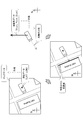
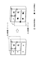
- FIG. 19 is an explanatory diagram for explaining an example of a configuration of feature data.
- the feature data 151 includes an object ID 152, image data 153 captured from six directions, patch data 154, and three-dimensional shape data 155.
- the object ID 152 is an identifier for uniquely identifying the real object Obj1.
- the image data 153 includes six pieces of image data obtained by imaging the real object Obj1 from six directions of front, rear, left, right, upper, and lower.
- the patch data 154 is a set of small images centered on each feature point for each feature point set on the real object.
- the three-dimensional shape data 155 is a position representing the three-dimensional position of each feature point in the local coordinate system of the real object Obj1 (that is, the position of each feature point relative to the origin defined locally in the real object Obj1). Contains information.
- the image recognition unit 156 recognizes which real object appears in the input image using the above-described feature data stored in the object DB 150. More specifically, for example, the image recognition unit 156 collates the partial image included in the input image acquired by the image acquisition unit 120 with the patch of each feature point included in the feature data, and is included in the input image. Detect feature points. The image recognition unit 156 may reuse the tracking result of the feature points by the SLAM calculation unit 145. Next, when the feature points belonging to one real object are detected at a high density in a certain area in the image, the image recognition unit 156 can recognize that the real object is reflected in the area.
- the image recognition unit 156 can further recognize the position and orientation of the recognized real object based on the positional relationship between the detected feature points and the three-dimensional shape data illustrated in FIG. Based on the position and posture of the real object recognized by the image recognition unit 156 and the position and posture of the imaging unit 102 recognized by the SLAM calculation unit 145, the position and posture of the real object after initialization of the SLAM method are determined. Tracking is realized. The position and orientation of the tracked real object are stored by the 3D structure DB 135.
- annotation DB 160 is a database that stores in advance annotation data related to annotations to be superimposed on an input image in the AR application.
- the annotation data may include, for example, identifiers, shape data, motion data, and related object IDs of various real objects including annotations A11, A12, and A2 illustrated in FIGS.
- the display control unit 165 controls display of the AR application using the display unit 110.
- the display control unit 165 arranges the annotation selected from the annotation DB 160 according to the purpose of the AR application in the AR space corresponding to the real space reflected in the input image.
- the arrangement of the annotation may be determined according to the position and orientation of the plane determined by the determination unit 130, for example.
- the conversion unit 140 uses the position and orientation of the plane on which the annotation is to be placed, using the two-dimensional position on the imaging surface corresponding to the feature points (or the vertices of the polygons, etc.) constituting the annotation placed in the AR space. calculate.
- the display control unit 165 superimposes the selected annotation on the input image in accordance with the calculation result by the conversion unit 140.
- the image on which the annotation is superimposed is displayed using the display of the display unit 110.
- the user interface unit 170 provides a user interface to the user of the information processing apparatus 100 using the input unit 106 and the display unit 110 illustrated in FIG.
- the user interface unit 170 displays an operation screen for allowing the user to operate the AR application on the display unit 110 and detects a user input through the operation screen.
- annotation selection, change, or movement may be performed via the user interface unit 170.
- the user interface unit 170 may superimpose on the input image a user interface for causing the user to designate a vertical plane shown in the input image on the map, as described with reference to FIG.
- the user interface unit 170 may superimpose a user interface for allowing the user to specify the posture of the arbitrary plane as described with reference to FIG. 12A on the input image in which the arbitrary plane is reflected.
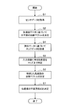
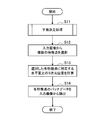
- FIG. 20 is a flowchart illustrating an example of the overall processing flow by the information processing apparatus 100 according to the present embodiment.
- an annotation to be displayed is selected by the display control unit 165 (or by the user via the user interface unit 170) (step S110).
- the display control unit 165 acquires, from the 3D structure DB 135, the 3D structure of the real space recognized based on the SLAM calculation (for example, the position and orientation of the real object or the plane associated with the selected annotation). (Step S120).
- the display control unit 165 arranges the selected annotation in the AR space according to the 3D structure of the real space (step S130).
- the conversion unit 140 calculates the display position of the annotation arranged in the AR space according to the above-described pinhole camera model (step S140). Then, the display control unit 165 superimposes the selected annotation on the input image according to the calculation result by the conversion unit 140 (step S150). As a result of such display control processing, display of the AR application as illustrated in FIGS. 1 and 2 can be realized.
- a normal vector of a horizontal plane in real space is recognized based on sensor data indicating the direction of gravity applied to the imaging device, and a plane such as a horizontal plane or a vertical plane is used using the recognized normal vector.
- the relative posture with respect to the imaging surface is determined.
- a state variable of the SLAM method is initialized by coordinate conversion using the determined plane orientation.
- the recognition accuracy in the vertical direction by the triaxial acceleration sensor is higher than the recognition of the horizontal plane based on the image recognition. Therefore, it is possible to initialize the state variable with higher accuracy than when the state variable is initialized using a method based on image recognition.
- the recognition accuracy at the time of initialization of the SLAM method affects the accuracy of the subsequent tracking of the 3D structure in the real space. Therefore, by initializing the state variables with higher accuracy, it is possible to accurately track the 3D structure in the real space thereafter.
- the relative position of the plane is easily determined as a temporary position. Therefore, the annotation is not arranged so as to completely coincide with the ground or floor surface of the real space.
- the accuracy of the posture is ensured with at least high accuracy, it is possible to superimpose an annotation that is arranged along a plane or moves on the plane in a natural manner.
- the purpose of the application can be sufficiently achieved if the orientation of the plane can be accurately determined without accurately determining the relative position of the plane.
- parallax is not used as in the SfM method in determining the orientation of the plane. Therefore, the orientation of the plane can be determined without moving the imaging device or in a situation where the imaging device is fixed.
- the posture of the horizontal plane can be determined easily and accurately using only sensor data from the three-axis acceleration sensor. Furthermore, by using predefined direction constraints, additional sensor data, or user input, the vertical plane attitude can also be accurately determined. It is also possible to determine the posture of an arbitrary plane via the user interface. Therefore, in many scenes where the AR application is used, it is possible to initialize the SLAM method with high accuracy by using various planes reflected in the input image.
- the adoption of the technology according to the present disclosure is also beneficial for AR applications that do not use the SLAM method. Therefore, as a second embodiment, an information processing apparatus 200 that implements an AR application that does not use the SLAM method will be described.
- the information processing apparatus 200 according to the present embodiment may be the terminal apparatus illustrated in FIG. 1 as with the information processing apparatus 100 according to the first embodiment, or the server illustrated in FIG. It may be a device.
- the information processing device 200 is a terminal device, the information processing device 200 may have a hardware configuration illustrated in FIG.
- FIG. 21 is a block diagram illustrating an example of a configuration of logical functions of the information processing apparatus 200 according to the second embodiment.
- the information processing apparatus 200 includes an image acquisition unit 120, a data acquisition unit 125, a determination unit 130, a 3D structure DB 135, a conversion unit 140, an object DB 150, an image recognition unit 156, an annotation DB 160, a user interface unit 170, and A display control unit 265 is included.
- the determination unit 130 determines the relative posture of the real space plane (horizontal plane, vertical plane, or arbitrary plane) with respect to the imaging surface based on the sensor data acquired by the data acquisition unit 125. Then, the determination unit 130 causes the 3D structure DB 135 to store the planar 3D structure having the determined posture.
- the conversion unit 140 calculates the two-dimensional position in the image (that is, on the imaging surface) corresponding to the three-dimensional position of a given point on the plane using the plane orientation determined by the determination unit 130. .
- a given point that is a target of calculation processing by the conversion unit 140 is a point that constitutes an annotation for an AR application.
- the image recognizing unit 156 recognizes which actual object appears in the input image using the feature data stored in the object DB 150. The result of recognition by the image recognition unit 156 may be used when the display control unit 265 selects and arranges annotation.
- the display control unit 265 controls the display of the AR application using the display. For example, the display control unit 265 arranges the annotation selected from the annotation DB 160 according to the purpose of the AR application in the AR space corresponding to the real space reflected in the input image.
- the arrangement of the annotation may be determined according to the recognition result of the real object by the image recognition unit 156. Instead, the annotation may be placed so as to be placed or pasted on a plane determined by the determination unit 130 and posted.
- the conversion unit 140 calculates a two-dimensional position on the imaging surface corresponding to a feature point (or a vertex of a polygon, etc.) constituting an annotation arranged in the AR space using the position and orientation of the real object or the plane. .
- the display control unit 265 superimposes the selected annotation on the input image in accordance with the calculation result by the conversion unit 140.
- FIG. 22 is a flowchart illustrating an example of the overall processing flow by the information processing apparatus 100 according to the present embodiment.
- the determination unit 130 performs a plane determination process (step S200).
- an annotation to be displayed is selected by the display control unit 265 (step S210).
- the display control unit 265 arranges the selected annotation in the AR space (step S230).
- the annotation may be arranged to be placed on a plane.
- the conversion unit 140 calculates the display position of the annotation arranged in the AR space according to the above-described pinhole camera model (step S240).
- the display control unit 265 superimposes the selected annotation on the input image according to the calculation result by the conversion unit 140 (step S250).
- display of the AR application as illustrated in FIGS. 1 and 2 can be realized.
- a normal vector of a horizontal plane in real space is recognized based on sensor data indicating the direction of gravity applied to the imaging device, and a horizontal plane, a vertical plane, or the like is used using the recognized normal vector.
- a relative posture of the plane with respect to the imaging surface is determined.
- the display position of the annotation arranged in association with the determined plane is easily calculated using the orientation of the plane.
- the recognition accuracy in the vertical direction by the triaxial acceleration sensor is higher than the recognition of the horizontal plane based on the image recognition. Therefore, it is possible to realize a more natural display of the annotation in the AR application as compared with the case where the annotation is arranged in association with the plane recognized using the method based on the image recognition.
- the posture of the horizontal plane can be determined easily and accurately using only sensor data from the three-axis acceleration sensor. Furthermore, by using predefined direction constraints, additional sensor data, or user input, the vertical plane attitude can also be accurately determined. It is also possible to determine the posture of an arbitrary plane via the user interface. Therefore, in many scenes where the AR application is used, it is possible to naturally display annotations in association with various planes reflected in the input image.
- the plane determined by the determination unit 130 has a virtual scale. That is, the value of the constant term D of the plane equation of the plane is a temporary value.
- the determination unit 130 may adjust the value of the constant term D so that the position of the plane coincides with the ground surface, the floor surface, the ceiling surface, or the surface of a real object (for example, the wall surface of a building). Further, the determination unit 130 may adjust the value of the constant term D according to the requirements of the AR application. In this section, three methods for adjusting the scale of a plane will be described using a horizontal plane as an example.
- a known size of a real object shown in an input image is used.
- the difference in position between two feature points belonging to one real object in the three-dimensional shape data (see FIG. 19) included in the feature data stored in the object DB 150 can be handled as a known size of the real object. .
- FIG. 23 is an explanatory diagram for describing a first technique for determining a plane scale.
- the two feature points T 1 and T 2 on the horizontal plane HP is shown.
- Feature point T 1 corresponds to the position U 1 on the imaging plane IP
- the feature point T 2 are corresponds to the position U 2 on the imaging plane IP.
- These feature points T 1 and T 2 belong to one real object.
- the image recognition unit 156 recognizes a real object including these feature points T 1 and T 2 from the input image.
- the determination unit 130 calculates a distance d HP between the feature points T 1 and T 2 from the three-dimensional shape data included in the feature data of the recognized real object. Then, the determination unit 130 uses the constant term D of the plane equation as an unknown variable, and derives a value of D at which the distance between the feature points T 1 and T 2 is d HP .
- [4-2. Second method] data related to the distance between the plane reflected in the input image and the imaging device is used.
- the plane reflected in the input image is a horizontal plane such as the ground or floor
- data related to the height of the imaging device from these horizontal planes can be used.
- the plane reflected in the input image is a vertical surface such as a wall surface of a building
- the distance between the wall surface calculated from the map data and the imaging device can be used.
- FIG. 24 is an explanatory diagram for explaining a second method for determining a plane scale.
- FIG. 24 shows the user Ua standing on the horizontal plane HP and the information processing apparatus 100 carried by the user Ua.
- the height of the user Ua is stored in advance as known data, or is input to the information processing apparatus 100 by the user Ua.
- the determination unit 130 estimates the height Ha of the imaging unit 102 of the information processing apparatus 100 by multiplying the height of the user Ua by a certain ratio.
- the determination unit 130 can use the height Ha thus estimated as the constant term D of the plane equation.
- the display size of the annotation displayed superimposed on the input image is used.
- the annotation DB 160 it is assumed that the size of the annotation in the three-dimensional AR space is defined.
- the plane scale can be determined from these two sizes.
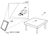
- FIG. 25 is a first explanatory diagram for describing a third technique for determining a plane scale.
- FIG. 25 shows an image Im11 showing the table 14 existing in the real space.
- the annotation A2 is superimposed on the image Im11 as if it were placed on the surface of the table 14.
- the AR application displays the annotation A2 with a display size d disp that is fixedly defined.
- the determining unit 130 determines the constant term D of the plane equation so that the annotation A2 arranged in the AR space has the display size d disp on the imaging surface.
- the display size of the annotation A2 arranged on the plane becomes a predetermined display size d disp .
- FIG. 26 is a second explanatory diagram for describing the third technique for determining the plane scale.
- FIG. 26 shows an image Im12 on which the annotation A2 is superimposed as if it is placed on the surface of the table.
- the display size d disp of the annotation A2 is designated by the user via the user interface unit 170.
- the determining unit 130 determines the constant term D of the plane equation so that the annotation A2 arranged in the AR space has the display size d disp on the imaging surface. As a result, the display size of the annotation A2 arranged on the plane becomes the specified display size d disp .
- the position of the plane can be matched with the actual ground surface, floor surface, ceiling surface, or surface of the real object reflected in the input image.
- the display of annotations associated with these existing planes becomes more natural.
- the annotation can be displayed in a desired display size by adjusting the scale of the plane.
- the technology according to the present disclosure displays, for example, a horizontal plane and a vertical plane at the time of positioning of the imaging device, or adds a sign indicating the horizontal plane or the vertical plane to a recorded image. It may be applied to various uses.
- some of the logical functions of the information processing apparatus 100 or 200 described above may be mounted on a device existing in the cloud computing environment instead of being mounted on these devices.
- information exchanged between logical functions can be transmitted or received between devices via the communication unit 112 illustrated in FIG.
- the series of processing by each device described in this specification may be realized using any of software, hardware, and a combination of software and hardware.
- a program constituting the software is stored in advance in a storage medium provided inside or outside each device.
- Each program is read into a RAM (Random Access Memory) at the time of execution and executed by a processor such as a CPU.
- RAM Random Access Memory
- a data acquisition unit that acquires sensor data indicating the direction of gravity applied to an imaging device that captures an image that reflects real space
- a determination unit that determines a relative posture of a plane of the real space with respect to the image based on the sensor data
- a conversion unit that performs conversion between a three-dimensional position of a given point on the plane and a corresponding two-dimensional position in the image using the posture determined by the determination unit;
- An information processing apparatus comprising: (2) The information processing apparatus according to (1), wherein the given point on the plane is a feature point selected during initialization of a SLAM (Simultaneous Localization And Mapping) method.
- SLAM Simultaneous Localization And Mapping
- the information processing apparatus determines a virtual plane having the posture and a temporary position determined based on the sensor data;
- the information processing apparatus further includes a display control unit that superimposes the annotation on the image, The annotation is superimposed on a two-dimensional position in the image converted by the conversion unit from a three-dimensional position on the virtual plane.
- the information processing apparatus according to (3).
- the information processing apparatus further includes a recognition unit that recognizes an object shown in the image, The determination unit further determines the position of the plane reflected in the image using known data about the actual size of the object recognized by the recognition unit.
- the information processing apparatus according to (2) or (3).
- the determination unit further determines the position of the plane using data related to the distance between the plane reflected in the image and the imaging device, according to any one of (1) to (3).
- the information processing apparatus described in 1. The information processing apparatus according to (3), wherein the determination unit further determines a position of the plane on which the annotation is arranged using a display size of the displayed annotation.
- the plane is a horizontal plane; The determining unit determines whether the imaging device is facing upward or downward based on the sensor data, and determines the posture of the horizontal plane according to a result of the determination.
- the information processing apparatus according to any one of (1) to (8).
- the plane is a vertical plane;
- the determining unit determines the posture of the vertical plane based on the sensor data indicating the direction of gravity and a predefined direction constraint.
- the information processing apparatus according to any one of (1) to (8).
- the plane is a vertical plane;
- the determining unit determines an attitude of the vertical plane based on the sensor data indicating a direction of gravity and map data indicating a positional relationship between the imaging device and the vertical plane.
- the information processing apparatus according to any one of (1) to (8).
- the determination unit estimates a vertical plane reflected in the image using sensor data indicating a direction of geomagnetism from one or more vertical plane candidates included in the map data, and determines the estimated posture of the vertical plane,
- the determination unit determines the posture of the vertical plane designated by the user from one or more vertical plane candidates included in the map data based on the map data and the direction of gravity. The information processing apparatus described.
- the information processing apparatus includes: A user interface unit that arranges a user interface in the augmented reality space for allowing the user to specify the orientation of the plane based on the orientation of the horizontal plane or the vertical plane determined based on the sensor data,
- the information processing apparatus according to any one of (1) to (8), further including: (15) The information processing apparatus according to (14), wherein the arrangement of the user interface is maintained in the augmented reality space over a plurality of frames.
- the user interface has an operation surface that can be three-dimensionally rotated, The determining unit determines the orientation of the plane using the orientation of the operation surface operated by a user so as to be parallel to the plane.
- the information processing apparatus according to (15).
- a computer that controls an information processing device, Acquiring sensor data indicating the direction of gravity applied to an imaging device that captures an image reflecting real space; Determining a relative orientation of the plane of the real space with respect to the image based on the sensor data; Performing a transformation between a three-dimensional position of a given point on the plane and a corresponding two-dimensional position in the image using the determined posture;
- An information processing method including: (20) A computer for controlling the information processing apparatus; A data acquisition unit that acquires sensor data indicating the direction of gravity applied to an imaging device that captures an image that reflects real space; A determination unit that determines a relative posture of a plane of the real space with respect to the image based on the sensor data; A conversion unit that performs conversion between a three-dimensional position of a given point on the plane and a corresponding two-dimensional position in the image using the posture determined by the determination unit; Program to function as.
Abstract
Priority Applications (6)
| Application Number | Priority Date | Filing Date | Title |
|---|---|---|---|
| EP12825620.3A EP2750110B1 (fr) | 2011-08-24 | 2012-08-14 | Dispositif de traitement d'informations, procédé de traitement d'informations et programme |
| US14/238,978 US9355451B2 (en) | 2011-08-24 | 2012-08-14 | Information processing device, information processing method, and program for recognizing attitude of a plane |
| EP20156603.1A EP3680863B1 (fr) | 2011-08-24 | 2012-08-14 | Dispositif de traitement d'informations, procédé de traitement d'informations et programme |
| RU2014105775/08A RU2014105775A (ru) | 2011-08-24 | 2012-08-14 | Устройство обработки информации, способ обработки информации и программа |
| CN201280040105.9A CN103733229A (zh) | 2011-08-24 | 2012-08-14 | 信息处理设备、信息处理方法及程序 |
| JP2013529976A JP5920352B2 (ja) | 2011-08-24 | 2012-08-14 | 情報処理装置、情報処理方法及びプログラム |
Applications Claiming Priority (2)
| Application Number | Priority Date | Filing Date | Title |
|---|---|---|---|
| JP2011182693 | 2011-08-24 | ||
| JP2011-182693 | 2011-08-24 |
Publications (1)
| Publication Number | Publication Date |
|---|---|
| WO2013027628A1 true WO2013027628A1 (fr) | 2013-02-28 |
Family
ID=47746375
Family Applications (1)
| Application Number | Title | Priority Date | Filing Date |
|---|---|---|---|
| PCT/JP2012/070677 WO2013027628A1 (fr) | 2011-08-24 | 2012-08-14 | Dispositif de traitement d'informations, procédé de traitement d'informations et programme |
Country Status (6)
| Country | Link |
|---|---|
| US (1) | US9355451B2 (fr) |
| EP (2) | EP2750110B1 (fr) |
| JP (1) | JP5920352B2 (fr) |
| CN (1) | CN103733229A (fr) |
| RU (1) | RU2014105775A (fr) |
| WO (1) | WO2013027628A1 (fr) |
Cited By (11)
| Publication number | Priority date | Publication date | Assignee | Title |
|---|---|---|---|---|
| GB2506338A (en) * | 2012-07-30 | 2014-04-02 | Sony Comp Entertainment Europe | A method of localisation and mapping |
| WO2015093129A1 (fr) * | 2013-12-17 | 2015-06-25 | ソニー株式会社 | Dispositif de traitement d'informations, procédé de traitement d'informations et programme |
| WO2016017254A1 (fr) * | 2014-08-01 | 2016-02-04 | ソニー株式会社 | Dispositif de traitement d'informations, procédé de traitement d'informations, et programme |
| WO2016017253A1 (fr) * | 2014-08-01 | 2016-02-04 | ソニー株式会社 | Dispositif de traitement d'informations, procédé de traitement d'informations et programme |
| JP2016038867A (ja) * | 2014-08-11 | 2016-03-22 | 株式会社大林組 | 配置計画支援システム、配置計画支援方法及び配置計画支援プログラム |
| JP2016048455A (ja) * | 2014-08-27 | 2016-04-07 | 株式会社リコー | 画像処理装置、画像処理方法、およびプログラム |
| JP2016515254A (ja) * | 2013-03-15 | 2016-05-26 | クアルコム,インコーポレイテッド | クライアント−サーバベースの動的検索 |
| JP2020509505A (ja) * | 2017-03-06 | 2020-03-26 | Line株式会社 | 拡張現実を提供するための方法、装置及びコンピュータプログラム |
| WO2020116352A1 (fr) * | 2018-12-04 | 2020-06-11 | アイシン精機株式会社 | Dispositif de détection de surface de route et programme de détection de surface de route |
| JP2020535509A (ja) * | 2017-09-29 | 2020-12-03 | アリババ・グループ・ホールディング・リミテッドAlibaba Group Holding Limited | イメージ内のターゲットオブジェクトに自動的にアノテーションするための方法、装置およびシステム |
| JP2023502192A (ja) * | 2020-10-23 | 2023-01-23 | チョーチアン センスタイム テクノロジー デベロップメント カンパニー,リミテッド | 視覚的ポジショニング方法および関連装置、機器並びにコンピュータ可読記憶媒体 |
Families Citing this family (23)
| Publication number | Priority date | Publication date | Assignee | Title |
|---|---|---|---|---|
| EP2983137B1 (fr) * | 2013-04-04 | 2019-05-22 | Sony Corporation | Dispositif et procédé de traitement d'informations, et programme |
| US20150269436A1 (en) * | 2014-03-18 | 2015-09-24 | Qualcomm Incorporated | Line segment tracking in computer vision applications |
| JP6525010B2 (ja) * | 2014-08-05 | 2019-06-05 | ソニー株式会社 | 情報処理装置及び情報処理方法、並びに画像表示システム |
| JP6459706B2 (ja) * | 2015-03-27 | 2019-01-30 | セイコーエプソン株式会社 | インタラクティブプロジェクター及びインタラクティブプロジェクションシステム |
| US10360718B2 (en) * | 2015-08-14 | 2019-07-23 | Samsung Electronics Co., Ltd. | Method and apparatus for constructing three dimensional model of object |
| CN107949866A (zh) * | 2015-09-15 | 2018-04-20 | 三菱电机株式会社 | 图像处理装置、图像处理系统和图像处理方法 |
| CN107025661B (zh) * | 2016-01-29 | 2020-08-04 | 成都理想境界科技有限公司 | 一种实现增强现实的方法、服务器、终端及系统 |
| CN107025662B (zh) * | 2016-01-29 | 2020-06-09 | 成都理想境界科技有限公司 | 一种实现增强现实的方法、服务器、终端及系统 |
| CN108629248A (zh) * | 2017-03-24 | 2018-10-09 | 成都理想境界科技有限公司 | 一种实现增强现实的方法及设备 |
| WO2018211782A1 (fr) * | 2017-05-18 | 2018-11-22 | ソニー株式会社 | Dispositif et procédé de traitement d'image, et programme |
| DE102017217923A1 (de) * | 2017-10-09 | 2019-04-11 | Audi Ag | Verfahren zum Betrieb einer Anzeigeeinrichtung in einem Kraftfahrzeug |
| CN107704106B (zh) * | 2017-10-17 | 2021-04-09 | 宁波视睿迪光电有限公司 | 姿态定位方法、装置及电子设备 |
| JP6770208B2 (ja) * | 2018-01-30 | 2020-10-14 | 株式会社ソニー・インタラクティブエンタテインメント | 情報処理装置 |
| WO2019164514A1 (fr) * | 2018-02-23 | 2019-08-29 | Google Llc | Transition entre une vue cartographique et une vue en réalité augmentée |
| CH714968A1 (de) * | 2018-05-07 | 2019-11-15 | Brugg Rohr Ag Holding | Verfahren und Vorrichtung zur Herstellung eines wärmegedämmten Leitungsrohrs. |
| US10482674B1 (en) * | 2018-06-27 | 2019-11-19 | Beijing Jingdong Shangke Information Technology Co., Ltd. | System and method for mobile augmented reality |
| US10628964B2 (en) * | 2018-09-19 | 2020-04-21 | Seiko Epson Corporation | Methods and devices for extended reality device training data creation |
| CN109579745A (zh) * | 2018-11-26 | 2019-04-05 | 江苏科技大学 | 基于增强现实和手机软件的新型房屋面积测算方法 |
| CN111256683A (zh) * | 2018-12-03 | 2020-06-09 | 北京科加触控技术有限公司 | 一种定位方法及装置 |
| JP2020089947A (ja) * | 2018-12-06 | 2020-06-11 | ソニー株式会社 | 情報処理装置、情報処理方法及びプログラム |
| JP7341736B2 (ja) * | 2019-06-06 | 2023-09-11 | キヤノン株式会社 | 情報処理装置、情報処理方法及びプログラム |
| US11430151B2 (en) | 2019-11-06 | 2022-08-30 | Seiko Epson Corporation | Online learning for 3D pose estimation using simplified constellations |
| JPWO2021124826A1 (fr) * | 2019-12-17 | 2021-06-24 |
Citations (4)
| Publication number | Priority date | Publication date | Assignee | Title |
|---|---|---|---|---|
| JP2005107248A (ja) * | 2003-09-30 | 2005-04-21 | Canon Inc | データ変換方法及び装置並びに姿勢計測装置 |
| JP2006292417A (ja) * | 2005-04-06 | 2006-10-26 | Canon Inc | 位置姿勢計測方法及び装置 |
| JP2007271563A (ja) * | 2006-03-31 | 2007-10-18 | Canon Inc | 位置姿勢計測方法及び装置 |
| JP2009237845A (ja) | 2008-03-27 | 2009-10-15 | Sony Corp | 情報処理装置、および情報処理方法、並びにコンピュータ・プログラム |
Family Cites Families (5)
| Publication number | Priority date | Publication date | Assignee | Title |
|---|---|---|---|---|
| CN101609506B (zh) * | 2008-06-20 | 2012-05-23 | 索尼株式会社 | 用于识别图像中的模型对象的装置及方法 |
| US8350871B2 (en) * | 2009-02-04 | 2013-01-08 | Motorola Mobility Llc | Method and apparatus for creating virtual graffiti in a mobile virtual and augmented reality system |
| KR101633359B1 (ko) * | 2009-10-20 | 2016-06-27 | 삼성전자 주식회사 | 투사 불변량을 이용한 무표식 증강 현실 구현 시스템 및 그 방법 |
| KR101667033B1 (ko) * | 2010-01-04 | 2016-10-17 | 삼성전자 주식회사 | 위치 기반 정보를 이용한 증강 현실 서비스 장치 및 그 방법 |
| US8797353B2 (en) * | 2010-02-12 | 2014-08-05 | Samsung Electronics Co., Ltd. | Augmented media message |
-
2012
- 2012-08-14 EP EP12825620.3A patent/EP2750110B1/fr active Active
- 2012-08-14 WO PCT/JP2012/070677 patent/WO2013027628A1/fr active Application Filing
- 2012-08-14 US US14/238,978 patent/US9355451B2/en active Active
- 2012-08-14 JP JP2013529976A patent/JP5920352B2/ja active Active
- 2012-08-14 CN CN201280040105.9A patent/CN103733229A/zh active Pending
- 2012-08-14 EP EP20156603.1A patent/EP3680863B1/fr active Active
- 2012-08-14 RU RU2014105775/08A patent/RU2014105775A/ru not_active Application Discontinuation
Patent Citations (4)
| Publication number | Priority date | Publication date | Assignee | Title |
|---|---|---|---|---|
| JP2005107248A (ja) * | 2003-09-30 | 2005-04-21 | Canon Inc | データ変換方法及び装置並びに姿勢計測装置 |
| JP2006292417A (ja) * | 2005-04-06 | 2006-10-26 | Canon Inc | 位置姿勢計測方法及び装置 |
| JP2007271563A (ja) * | 2006-03-31 | 2007-10-18 | Canon Inc | 位置姿勢計測方法及び装置 |
| JP2009237845A (ja) | 2008-03-27 | 2009-10-15 | Sony Corp | 情報処理装置、および情報処理方法、並びにコンピュータ・プログラム |
Non-Patent Citations (2)
| Title |
|---|
| ANDREW J. DAVISON: "Real-Time Simultaneous Localization and Mapping with a Single Camera", PROCEEDINGS OF THE 9TH IEEE INTERNATIONAL CONFERENCE ON COMPUTER VISION VOLUME, vol. 2, 2003, pages 1403 - 1410 |
| See also references of EP2750110A4 |
Cited By (32)
| Publication number | Priority date | Publication date | Assignee | Title |
|---|---|---|---|---|
| US9415310B2 (en) | 2012-07-30 | 2016-08-16 | Sony Computer Entertainment Europe Limited | Localisation and mapping |
| US10657663B2 (en) | 2012-07-30 | 2020-05-19 | Sony Interactive Entertainment Europe Limited | Localisation and mapping |
| GB2506338A (en) * | 2012-07-30 | 2014-04-02 | Sony Comp Entertainment Europe | A method of localisation and mapping |
| US9824450B2 (en) | 2012-07-30 | 2017-11-21 | Sony Interactive Entertainment Europe Limited | Localisation and mapping |
| US9779509B2 (en) | 2012-07-30 | 2017-10-03 | Sony Interactive Entertainment Europe Limited | Localisation and mapping |
| US9704244B2 (en) | 2012-07-30 | 2017-07-11 | Sony Computer Entertainment Europe Limited | Localisation and mapping |
| US9679381B2 (en) | 2012-07-30 | 2017-06-13 | Sony Computer Entertainment Europe Limited | Localisation and mapping |
| JP2016515254A (ja) * | 2013-03-15 | 2016-05-26 | クアルコム,インコーポレイテッド | クライアント−サーバベースの動的検索 |
| US10452892B2 (en) | 2013-12-17 | 2019-10-22 | Sony Corporation | Controlling image processing device to display data based on state of object in real space |
| CN105814611B (zh) * | 2013-12-17 | 2020-08-18 | 索尼公司 | 信息处理设备和方法以及非易失性计算机可读存储介质 |
| US11462028B2 (en) | 2013-12-17 | 2022-10-04 | Sony Corporation | Information processing device and information processing method to generate a virtual object image based on change in state of object in real space |
| WO2015093129A1 (fr) * | 2013-12-17 | 2015-06-25 | ソニー株式会社 | Dispositif de traitement d'informations, procédé de traitement d'informations et programme |
| CN105814611A (zh) * | 2013-12-17 | 2016-07-27 | 索尼公司 | 信息处理设备、信息处理方法、以及程序 |
| JPWO2015093129A1 (ja) * | 2013-12-17 | 2017-03-16 | ソニー株式会社 | 情報処理装置、情報処理方法およびプログラム |
| WO2016017253A1 (fr) * | 2014-08-01 | 2016-02-04 | ソニー株式会社 | Dispositif de traitement d'informations, procédé de traitement d'informations et programme |
| WO2016017254A1 (fr) * | 2014-08-01 | 2016-02-04 | ソニー株式会社 | Dispositif de traitement d'informations, procédé de traitement d'informations, et programme |
| US10462406B2 (en) | 2014-08-01 | 2019-10-29 | Sony Corporation | Information processing apparatus and information processing method |
| US10499002B2 (en) | 2014-08-01 | 2019-12-03 | Sony Corporation | Information processing apparatus and information processing method |
| JPWO2016017253A1 (ja) * | 2014-08-01 | 2017-05-18 | ソニー株式会社 | 情報処理装置、および情報処理方法、並びにプログラム |
| JPWO2016017254A1 (ja) * | 2014-08-01 | 2017-05-18 | ソニー株式会社 | 情報処理装置、および情報処理方法、並びにプログラム |
| JP2016038867A (ja) * | 2014-08-11 | 2016-03-22 | 株式会社大林組 | 配置計画支援システム、配置計画支援方法及び配置計画支援プログラム |
| JP2016048455A (ja) * | 2014-08-27 | 2016-04-07 | 株式会社リコー | 画像処理装置、画像処理方法、およびプログラム |
| JP2020509505A (ja) * | 2017-03-06 | 2020-03-26 | Line株式会社 | 拡張現実を提供するための方法、装置及びコンピュータプログラム |
| US11120629B2 (en) | 2017-03-06 | 2021-09-14 | Line Corporation | Method and device for providing augmented reality, and computer program |
| US11562545B2 (en) | 2017-03-06 | 2023-01-24 | Line Corporation | Method and device for providing augmented reality, and computer program |
| JP2020535509A (ja) * | 2017-09-29 | 2020-12-03 | アリババ・グループ・ホールディング・リミテッドAlibaba Group Holding Limited | イメージ内のターゲットオブジェクトに自動的にアノテーションするための方法、装置およびシステム |
| JP7231306B2 (ja) | 2017-09-29 | 2023-03-01 | アリババ・グループ・ホールディング・リミテッド | イメージ内のターゲットオブジェクトに自動的にアノテーションするための方法、装置およびシステム |
| JP2020090138A (ja) * | 2018-12-04 | 2020-06-11 | アイシン精機株式会社 | 路面検出装置および路面検出プログラム |
| WO2020116352A1 (fr) * | 2018-12-04 | 2020-06-11 | アイシン精機株式会社 | Dispositif de détection de surface de route et programme de détection de surface de route |
| JP7211047B2 (ja) | 2018-12-04 | 2023-01-24 | 株式会社アイシン | 路面検出装置および路面検出プログラム |
| JP2023502192A (ja) * | 2020-10-23 | 2023-01-23 | チョーチアン センスタイム テクノロジー デベロップメント カンパニー,リミテッド | 視覚的ポジショニング方法および関連装置、機器並びにコンピュータ可読記憶媒体 |
| JP7280385B2 (ja) | 2020-10-23 | 2023-05-23 | チョーチアン センスタイム テクノロジー デベロップメント カンパニー,リミテッド | 視覚的ポジショニング方法および関連装置、機器並びにコンピュータ可読記憶媒体 |
Also Published As
| Publication number | Publication date |
|---|---|
| EP2750110B1 (fr) | 2020-03-18 |
| RU2014105775A (ru) | 2015-08-27 |
| CN103733229A (zh) | 2014-04-16 |
| EP2750110A4 (fr) | 2015-08-26 |
| EP3680863A1 (fr) | 2020-07-15 |
| US20140168268A1 (en) | 2014-06-19 |
| EP3680863B1 (fr) | 2024-01-10 |
| JPWO2013027628A1 (ja) | 2015-03-19 |
| EP2750110A1 (fr) | 2014-07-02 |
| US9355451B2 (en) | 2016-05-31 |
| JP5920352B2 (ja) | 2016-05-18 |
Similar Documents
| Publication | Publication Date | Title |
|---|---|---|
| JP5920352B2 (ja) | 情報処理装置、情報処理方法及びプログラム | |
| US9996982B2 (en) | Information processing device, authoring method, and program | |
| TWI505709B (zh) | 擴增實境場景中決定個體化深度資訊的系統和方法 | |
| EP3176757A1 (fr) | Dispositif de traitement d'informations, procédé de traitement d'informations et programme | |
| WO2020227734A1 (fr) | Procédés et appareil de réalité augmentée s'appuyant sur un lieu | |
| US20140267234A1 (en) | Generation and Sharing Coordinate System Between Users on Mobile | |
| Bostanci et al. | User tracking methods for augmented reality | |
| US20140009384A1 (en) | Methods and systems for determining location of handheld device within 3d environment | |
| JP2013225245A (ja) | 画像処理装置、画像処理方法及びプログラム | |
| JP6609640B2 (ja) | 電子デバイス上における環境マッピング用のフィーチャ・データの管理 | |
| JP2011095797A (ja) | 画像処理装置、画像処理方法及びプログラム | |
| JP2011186808A (ja) | 情報処理装置、マップ更新方法、プログラム及び情報処理システム | |
| JP2011203823A (ja) | 画像処理装置、画像処理方法及びプログラム | |
| Marto et al. | DinofelisAR demo augmented reality based on natural features | |
| Ye et al. | 6-DOF pose estimation of a robotic navigation aid by tracking visual and geometric features | |
| JP2011203824A (ja) | 画像処理装置、画像処理方法及びプログラム | |
| Alam et al. | Pose estimation algorithm for mobile augmented reality based on inertial sensor fusion. | |
| TWI722738B (zh) | 擴增實境裝置與定位方法 | |
| Araujo et al. | Life cycle of a slam system: Implementation, evaluation and port to the project tango device | |
| WO2023226593A1 (fr) | Procédé, système et appareil d'affichage d'image, dispositif et support d'enregistrement | |
| Bostanci et al. | Tracking methods for augmented reality | |
| JPWO2021111613A1 (ja) | 3次元地図作成装置、3次元地図作成方法、及び3次元地図作成プログラム | |
| WO2024095744A1 (fr) | Dispositif de traitement d'informations, procédé de traitement d'informations et programme | |
| Li | A new efficient pose estimation and tracking method for personal devices: application to interaction in smart spaces | |
| Gu et al. | Research on the Key Techniques of Augmented Reality Navigation |
Legal Events
| Date | Code | Title | Description |
|---|---|---|---|
| 121 | Ep: the epo has been informed by wipo that ep was designated in this application |
Ref document number: 12825620 Country of ref document: EP Kind code of ref document: A1 |
|
| ENP | Entry into the national phase |
Ref document number: 2013529976 Country of ref document: JP Kind code of ref document: A |
|
| WWE | Wipo information: entry into national phase |
Ref document number: 14238978 Country of ref document: US |
|
| ENP | Entry into the national phase |
Ref document number: 2014105775 Country of ref document: RU Kind code of ref document: A |
|
| NENP | Non-entry into the national phase |
Ref country code: DE |