WO2013026319A1 - 小区测量方法、信息处理方法、终端、基站和网络系统 - Google Patents
小区测量方法、信息处理方法、终端、基站和网络系统 Download PDFInfo
- Publication number
- WO2013026319A1 WO2013026319A1 PCT/CN2012/077410 CN2012077410W WO2013026319A1 WO 2013026319 A1 WO2013026319 A1 WO 2013026319A1 CN 2012077410 W CN2012077410 W CN 2012077410W WO 2013026319 A1 WO2013026319 A1 WO 2013026319A1
- Authority
- WO
- WIPO (PCT)
- Prior art keywords
- cell
- base station
- information
- terminal
- measurement
- Prior art date
Links
Classifications
-
- H—ELECTRICITY
- H04—ELECTRIC COMMUNICATION TECHNIQUE
- H04W—WIRELESS COMMUNICATION NETWORKS
- H04W36/00—Hand-off or reselection arrangements
- H04W36/0005—Control or signalling for completing the hand-off
- H04W36/0055—Transmission or use of information for re-establishing the radio link
- H04W36/0077—Transmission or use of information for re-establishing the radio link of access information of target access point
-
- H—ELECTRICITY
- H04—ELECTRIC COMMUNICATION TECHNIQUE
- H04W—WIRELESS COMMUNICATION NETWORKS
- H04W48/00—Access restriction; Network selection; Access point selection
- H04W48/16—Discovering, processing access restriction or access information
-
- H—ELECTRICITY
- H04—ELECTRIC COMMUNICATION TECHNIQUE
- H04W—WIRELESS COMMUNICATION NETWORKS
- H04W36/00—Hand-off or reselection arrangements
- H04W36/0005—Control or signalling for completing the hand-off
- H04W36/0083—Determination of parameters used for hand-off, e.g. generation or modification of neighbour cell lists
- H04W36/0085—Hand-off measurements
- H04W36/0094—Definition of hand-off measurement parameters
-
- H—ELECTRICITY
- H04—ELECTRIC COMMUNICATION TECHNIQUE
- H04W—WIRELESS COMMUNICATION NETWORKS
- H04W48/00—Access restriction; Network selection; Access point selection
- H04W48/08—Access restriction or access information delivery, e.g. discovery data delivery
- H04W48/12—Access restriction or access information delivery, e.g. discovery data delivery using downlink control channel
Definitions
- the present invention relates to the field of wireless communication mobility management technologies, and in particular, to a cell measurement method, an information processing method, a terminal, a base station, a network system, and a network device.
- a heterogeneous network means that low-power nodes are placed in the coverage area of the macro base station to form a heterogeneous system covering different node types that overlap.
- the low power nodes include WIFI hotspots, LTE-Lomo (low mobility) nodes, etc.
- the introduction of these low power nodes solves the above capacity problem.
- a cell measurement scheme for overlay coverage in the current mobility management technology for example, a measurement scheme for the above WIFI hotspot cell and LTE-Lomo cell.
- a cell measurement scheme uses a dedicated radio unit, and continuous measurement and search, such as UEs that support WIFI functions, will continue to search for corresponding functions.
- the WIFI hotspot cell because the WIFI cell deployment is distributed, the UE consumes a large amount of power; the other cell measurement scheme uses the same measurement scheme as the mobility management of the macro cell of the traditional homogeneous network.
- the scheme can start the measurement of the low-power node cell in the case that the macro cell signal is not good, and the possibility that the UE starts the measurement is small, and it is difficult to implement effective splitting of the low-power node cell to the macro cell.
- a cell measurement method including: detecting, by a terminal accessing a first cell, signaling of a third cell; after detecting signaling of a third cell, performing measurement on a second cell; The third cell is co-frequency, the first cell is different from the second cell, and the second cell is associated with the third cell.
- An information processing method provided includes: receiving, by a base station of a first cell, information related to a second cell and/or a third cell managed by the second base station, or receiving, by the second base station, The second cell corresponding to the second base station and the third cell managed by the third base station, or the second base station and the third base station of the second base station Information associated with the cell, or receiving information associated with the second cell and the third cell from the operation management system; the third cell is co-frequency with the first cell formed by the base station, and the second cell is Transmitting, by the first cell, information related to the third cell according to the received information, and storing the associated information.
- a terminal includes: a detecting unit, configured to detect signaling of a third cell, where the third cell is a cell with the same frequency as the first cell accessed by the terminal; a measuring unit, configured to: after the detecting unit detects the signaling of the third cell, perform measurement on the second cell, where the second cell is a cell that is associated with the third cell and is different from the first cell .
- a base station is provided, including: a first radio frequency unit, configured to form a second cell;
- a second radio unit configured to form a third cell that is different from the second cell; and a processing unit, configured to generate synchronization signaling according to the PCI in the specific third cell physical cell identity (PCI) group, and by using the The second radio unit transmits the generated synchronization signaling on the third cell.
- Another base station including: a storage unit, configured to store information related to a second cell and a third cell, where the third cell is co-frequency with a first cell formed by the base station, and the second cell is The first cell is configured to receive the third cell identifier information from the terminal, the terminal accesses the first cell, and the measurement configuration unit is configured to use the corresponding relationship stored by the storage unit.
- a further base station comprising: a communication unit, configured to receive information about a second cell and/or a third cell that is identifiable by the second base station and is sent by the second base station, or And the information about the second cell and the third cell that are controlled by the second base station, or the information about the second cell that is controlled by the second base station and the third that is sent by the third base station Information of the third cell that is managed by the base station; the third cell is in the same frequency as the first cell formed by the base station, the second cell is different from the first cell; and the processing unit is configured to receive according to the The information generates information associated with the second cell and the third cell, and is stored in the storage unit.
- a further base station is provided, comprising: a radio frequency unit, configured to form a first cell;
- a processing unit configured to broadcast specific third cell PCI group information on the first cell, and/or to broadcast a correspondence between specific third cell PCI group information and frequency information of the second cell;
- the PCI in the PCI group of the third cell corresponds to the third cell in the same frequency of the first cell, and the second cell is a cell that is different from the first cell and is associated with the third cell.
- a network system including: a first base station, configured to form a first cell; and a second base station, configured to form a second cell that is different from the first cell;
- a third base station configured to form a third cell that is covered by the second cell, and send synchronization signaling for the terminal to launch the third cell PCI, where the third cell and the first The cell is in the same frequency, and the PCI is a PCI in a specific third cell PCI group.
- the third cell that is in the same frequency as the first cell is configured to be associated with the second cell, so that the terminal accessing the first cell can determine whether the second cell exists by detecting the signaling of the third cell, and When it is determined that the second cell exists, the measurement of the second cell is started; or the second cell location information acquired from the base station to which the first cell belongs, and the location information of the terminal accessing the first cell, Whether the terminal is close to the second cell, when detecting that the terminal is close to the second cell, starting measurement of the approaching second cell by the terminal; providing a cell measurement scheme different from the prior art.
- FIG. 1 is a flow chart of an embodiment of a method of the present invention
- Figure la is another flow chart of an embodiment of the method of the present invention.
- Figure 5 is a flow chart showing an exemplary preferred embodiment 1 of the method of the present invention.
- FIG. 6 is an exemplary application scenario of an exemplary preferred embodiment 1 of the method of the present invention
- FIG. 7 is a flowchart of an exemplary preferred embodiment 2 of the method of the present invention
- FIG. 8 is a schematic diagram of a network deployment according to an exemplary preferred embodiment 3 of the method of the present invention
- FIG. 9 is a schematic diagram of another network deployment according to an exemplary preferred embodiment 3 of the method of the present invention. a flow chart of a preferred embodiment 3;
- Figure 10a is a flow chart of an exemplary preferred embodiment 4 of the method of the present invention.
- Figure 10b is a flow chart of an exemplary preferred embodiment 5 of the method of the present invention.
- FIG. 11 is a schematic structural diagram of a terminal embodiment of the present invention.
- FIG. 12 is a schematic structural diagram of another embodiment of a terminal according to the present invention.
- FIG. 13 is another schematic structural diagram of a terminal embodiment of the present invention.
- 15 is another schematic structural diagram of a terminal embodiment of the present invention.
- 16 is another schematic structural diagram of an embodiment of a terminal according to the present invention.
- 17 is another schematic structural diagram of a terminal embodiment of the present invention.
- FIG. 18 is a schematic structural diagram of an embodiment of a base station according to the present invention.
- FIG. 19 is a schematic structural diagram of another embodiment of a base station according to the present invention.
- FIG. 19 is a schematic structural diagram of still another base station according to an embodiment of the present disclosure
- FIG. 19 is a schematic structural diagram of another base station according to an embodiment of the present invention
- FIG. 19 is a schematic structural diagram of another base station according to an embodiment of the present invention
- FIG. 21 is a schematic structural diagram of an embodiment of a network device according to the present invention.
- FIG. 23 is another schematic structural diagram of an embodiment of a network device according to the present invention.
- FIG. 24 is a schematic structural diagram of another embodiment of a network device according to the present invention
- FIG. 25 is another schematic structural diagram of an embodiment of a network device according to the present invention.
- an embodiment of a cell measurement method includes the following steps: Step 101: A terminal accessing a first cell detects a signaling of a third cell.
- Step 102 After detecting signaling of the third cell, perform measurement on the second cell.
- the first cell is co-frequency with the third cell, the first cell is different from the second cell, and the second cell is associated with the third cell.
- the first cell may be a macro cell, and the second cell is a cell in the macro cell coverage area or a cell adjacent to the macro cell.
- the foregoing second cell and the third cell may be: the second cell and the third cell are in the same coverage, or the coverage of the third cell includes a coverage range of the second cell;
- the measuring the second cell may include: determining, according to the detected signaling of the third cell, that the terminal is close to the second cell or entering a coverage of the second cell, and performing measurement on the second cell. .
- the information of the specific third cell PCI group may be saved in the foregoing terminal;
- the detecting, by the terminal accessing the first cell, the signaling of the third cell may include: the terminal accessing the first cell performing the same-frequency neighboring cell measurement, and according to the synchronization signaling detected in the measurement, pushing out the sending synchronization signaling
- the physical cell of the cell identifies the PCI, and determines whether the PCI belongs to the specific third cell PCI group saved above, to determine whether the detected synchronization signaling is signaling of the third cell.
- the foregoing third cell PCI group information may be pre-stored in the terminal; the terminal may also receive a Radio Resource Control (RRC) message, such as dedicated RRC signaling, sent by the base station to which the first ' ⁇ ! Obtaining the specific third cell PCI group information included in the RRC signaling, and acquiring the specific third cell PCI group information included in the system broadcast message by receiving the system broadcast message of the first cell; The system broadcast message of any neighboring cell acquires specific PCI group information included in the system broadcast message of the neighboring cell.
- the foregoing measuring the second cell may include: the foregoing terminal performs measurement on all frequencies supported by the terminal and different frequencies from the first cell.
- the foregoing terminal may save the correspondence between the specific third cell PCI group and the second cell frequency information; after the terminal accessing the first cell detects the signaling of the third cell, the measuring the second cell may include: The terminal accessing the first cell performs the same-frequency neighboring cell measurement, and according to the synchronization signaling detected in the measurement, the physical cell identifier PCI of the cell that sends the synchronization signaling is pushed out to determine whether the PCI belongs to a specific third cell PCI group.
- Corresponding relationship between the specific third cell PCI group and the second cell frequency information saved in the terminal And the RRC message sent by the base station to which the terminal belongs, such as dedicated RRC signaling, may be obtained by using the RRC message sent by the base station to which the first cell belongs, or may be obtained by the terminal. It is obtained by the terminal receiving the system broadcast message of the first cell, and may be obtained by the terminal by receiving a system broadcast message of any neighboring cell of the first cell.
- the foregoing further performing the measurement on the second cell may further include:
- the terminal sends the information close indication of the third cell to the base station to which the first cell belongs, and receives the measurement configuration information fed back by the base station to which the first cell belongs;
- the foregoing measuring the second cell may include: performing measurement according to the received measurement configuration information.
- the received measurement configuration information may include: measurement configuration information determined by the base station of the first cell according to the frequency information of the inter-frequency cell and/or the adjacent inter-frequency cell in the coverage of the first cell after receiving the proximity indication.
- the proximity indication may include the PCI of the third cell detected by the terminal;
- the received measurement configuration information may include: a correspondence between the third cell PCI group and the second cell frequency information saved by the base station of the first cell after receiving the proximity indication, and the PCI in the proximity indication, Obtaining second cell frequency information, and determining measurement configuration information according to the acquired second cell frequency information;
- the received measurement configuration information may include: after receiving the proximity indication, the base station of the first cell determines to associate with the third cell according to the cell association relationship table configured in the first cell and the PCI included in the proximity indication.
- the second cell according to the determined frequency information of the second cell, determines the measurement configuration information.
- the foregoing proximity indication may also include the second cell frequency information acquired by the terminal.
- the received measurement configuration information may include: the measurement configuration information determined by the base station of the first cell according to the second cell frequency information in the proximity indication.
- the foregoing terminal performing measurement on all frequencies supported by the first cell and the inter-frequency may include: The terminal determines whether it is necessary to start the GAP, and if so, performs measurement according to the GAP on all frequencies supported by the first ' ⁇ !, zone, and sends the GAP pattern to the network side; otherwise, directly in the supported And measuring on all frequencies different from the first cell.
- the measurement configuration information fed back by the associated base station includes: the base station to which the first cell belongs, determining the second association with the third cell according to the third cell identifier in the measurement report and the cell association relationship table configured in the same And determining, by the cell, measurement configuration information according to the determined frequency information of the second cell.
- the embodiment may further include: Step 103: When the measured signal quality of the second cell can meet the service communication of the terminal, the terminal accesses Go to the second cell above.
- the terminal accessing the foregoing second cell may include: the terminal accessing the second cell, and disconnecting the signaling connection with the first cell; or: the terminal accessing the second cell, and maintaining The signaling connection of the first cell.
- the third cell that is in the same frequency as the first cell is configured to be associated with the second cell, so that the terminal accessing the first cell can determine whether the second cell exists by detecting the signaling of the third cell, and When it is determined that the second cell exists, that is, the second cell is measured, a cell measurement scheme different from the prior art is provided.
- the foregoing solution when the foregoing solution is applied to the multi-cell coverage overlapping scenario, on the one hand, the foregoing solution reduces the power consumption of the UE by continuously performing cell search; on the other hand, the first cell is a macro cell, and the second cell is In the case of a low-power node cell, when the macro cell signal is good, the measurement of the low-power node cell can also be started by applying the above solution, and the start-up measurement is not affected by the macro cell signal, so that the low-power node cell divides the macro cell more. Fast and effective. As shown in FIG.
- Step 201 The base station of the first cell receives the information associated with the second cell and/or the third cell that is controlled by the second base station, or receives the information that is sent by the second base station by the second base station.
- the third cell is co-frequency with the first cell formed by the base station, and the second cell is different from the first cell;
- Step 202 Generate information related to the second cell and the third cell according to the received information, and store the information in a storage unit.
- the received information is carried in an X2 Setup Request (SETUP REQUEST) message, an X2 Setup Response (SETUP RESPONSE) message, or an X2 configuration update (ENB configuration update) message.
- the first ' ⁇ !, the base station to which the area belongs may perform the foregoing method embodiments or subsequent method embodiments, or the base station and access unit in the first cell in the subsequent base station embodiments.
- Various schemes for terminal communication of a cell In the preferred embodiment, the categories of the first cell, the second cell, and the third cell may be the same as in the previous embodiment, and details are not described herein again.
- the base station acquires the information of the associated second cell and the third cell, and stores the information in the second cell and the third cell, and the following may assist the terminal to determine whether the cell to which the cell is connected has an associated cell, or may assist the access.
- the terminal of a cell acquires the information of the second cell associated with the third cell that it can detect, so that the terminal can perform measurement on the associated second cell.
- another embodiment of the cell measurement method includes the following steps: Step 301: Monitor, according to second cell location information acquired from a base station to which the first cell belongs, and location information of a terminal accessing the first cell. Whether the above terminal is close to the second cell.
- the first cell may be a macro cell
- the second cell may be a cell that is within the coverage of the macro cell or a cell that is adjacent to the macro cell and has a common coverage area, such as a WiFi hotspot cell, Lomo (supports low-speed mobile Small site, or HIFI) cell, Dynamic spectrum share (DSS) cell (ie, can work in the downlink service) a cell in an uplink resource, such as an uplink carrier of an FDD or an uplink subframe of a TDD, or another MIMO cell, a Pico cell, a Radio Remote Head (RRH) cell, and a relay (Relay) A non-macro cell such as a cell.
- Step 302 When it is detected that the terminal is close to the second cell, start measuring, by the terminal, the second cell. In this embodiment, by comparing the location information of the terminal and the second cell, determining whether to initiate measurement of the second cell by the terminal, on the one hand, the terminal does not need to continuously search for the WIFI hotspot cell, thereby saving power consumption of the terminal; Since the measurement of the second cell does not consider the signal quality of the first cell, when the signal quality of the first cell is good, the measurement of the second cell can be started according to the location information, thereby improving the timeliness of the measurement.
- the second cell provides the possibility to more efficiently split the first cell terminal.
- the terminal by acquiring the location information data of the second cell from the base station, the terminal does not need to save the data of the second cell, thereby saving the storage space of the terminal, and ensuring the terminal location can be obtained more quickly and accurately.
- the nearby second cell information enables the measurement of the second cell to be initiated more quickly and accurately.
- the second cell is not limited to the low-power node cell, and the transmit power of the cell base station or the cell node is not lower than that of the macro cell, but it is within the coverage of the macro cell, or adjacent, and is used to The cells split by the network where the macro cell is located belong to the second cell.
- the above-described flow shown in FIG. 3 may be performed by a base station or by a terminal.
- the base station to which the macro cell belongs acquires the location information of the terminal, acquires the location information of the LPN cell saved in the self, and determines whether the terminal is close to the LPN cell according to the acquired information.
- starting the measurement by the terminal to the LPN cell may include: sending, by the base station to which the macro cell belongs, a notification message to the terminal, notifying the Said terminal is close to the LPN cell, so that the terminal initiates measurement of the approaching LPN cell according to the notification message;
- the detecting the measurement of the foregoing LPN cell by the terminal may include: the base station to which the macro cell belongs to configure the measurement configuration information for the terminal, and send the configured measurement configuration information to the terminal, so that the terminal according to the configured measurement configuration information The above-mentioned LPN cells are measured.
- the foregoing step 301 is specifically: the terminal acquires location information of the LPN cell from the base station, and obtains its own location information, and determines, according to the obtained information, whether the terminal is close to the LPN cell.
- the base station may broadcast the LPN cell location information covered by all or part of the macro cell in the system broadcast message of the macro cell, or further broadcast the location information of the neighboring LPN cell. Then, the terminal can obtain the location information of the LPN cell by receiving the system broadcast message of the macro cell.
- the location information of the terminal itself may be obtained through the GPS positioning unit of the terminal, or may be the location information obtained by the terminal using other positioning technologies.
- starting the measurement by the terminal to the LPN cell may include: the UE automatically starting measurement of the neighboring LPN cell. Then, when the base station broadcasts the location information of the LPN cell, the base station simultaneously broadcasts information for measuring the LPN cell, such as the physical cell identifier (PCI) of the LPN cell and/or the global cell identifier (GCI), and the terminal may use the broadcast to measure the LPN. The information of the cell initiates measurements of the nearby LPN cell.
- PCI physical cell identifier
- GCI global cell identifier
- the detecting, by the terminal, the measurement of the LPN cell may include: the UE notifying the base station to which the macro cell belongs to the information of the UE close to the LPN cell, and receiving the LPN cell fed back by the base station to which the macro cell belongs.
- the configuration information is measured, and the measurement of the approaching LPN cell is initiated based on the measurement configuration information.
- the embodiment may further include:
- Step 303 When the foregoing measurement result satisfies an access condition, the terminal is connected to the upper end. Said LPN cell.
- the measurement result satisfies the access condition: the signal quality of the foregoing LPN cell can satisfy the service communication of the terminal.
- the terminal is connected to the LPN cell, and the terminal is connected to the LPN cell after the signal quality of the macro cell and the LPN cell is different in the prior art.
- the foregoing step of accessing the terminal to the LPN cell may include: accessing the UE to the LPN cell, and disconnecting the signaling connection between the UE and the macro cell.
- the foregoing step of accessing the terminal to the LPN cell may include: accessing the UE to the LPN cell, and maintaining a signaling connection between the UE and the macro cell. And after the foregoing maintaining the signaling connection between the UE and the macro cell, the method further includes: the base station to which the macro cell belongs transfers all the services of the UE to the LPN cell accessed by the UE.
- the foregoing may further include: the foregoing, by the macro cell, transferring part of the service of the UE to the LPN cell; specifically, the UE may send a signaling to the base station after successfully accessing the LPN cell. If the information of the LPN cell is successfully accessed, the base station determines whether all the services of the 4 B UE are transferred to the LPN cell or the 4 B UE are transferred to the LPN cell according to the characteristics of the service and the load condition of the macro cell.
- the foregoing solution when the foregoing solution is applied to the multi-cell coverage overlapping scenario, on the one hand, the foregoing solution reduces the power consumption of the UE by continuously performing cell search; on the other hand, the first cell is a macro cell, and the second cell is In the case of a low-power node cell, when the macro cell signal is good, the measurement of the low-power node cell can also be started by applying the above solution, and the measurement is started without the macro cell signal. The impact makes the shunting of the macro cell to the low power node cell more rapid and effective.
- the location information of the terminal is obtained by the macro cell base station, and whether the measurement of the LPN cell is started is determined according to the location information of the terminal and the location information of the LPN cell acquired by the UE.
- the terminal is connected to the LPN cell, so as to more effectively divert the terminal in the macro cell.
- the location deployment information of the LPN cell in the network is saved in the database on the network side.
- the location deployment information may include a correspondence between the base station ID (and/or the cell ID) and the location information, where the location information may include the longitude and the dimension of the cell base station. And height, or may further include range data such as transmit power and/or coverage radius.
- the location deployment information of the foregoing LPN cell may be directly stored in a background device of the base station and/or the base station, and/or stored in a dedicated server.
- the base station obtains by querying the dedicated server.
- the LPN cell involved includes the LPN cell within the coverage of the base station, or includes the LPN cell and the adjacent LPN cell within the coverage.
- the base station can exchange location information through the X2 port.
- the newly added LPN cell base station can assist by sending an X2 SETUP REQUEST message, an X2 SETUP RESPONSE message, or an X2 ENB configuration update message to the macro cell base station. Update and improve the location information of the LPN cell base station.
- the contents of the above X2 SETUP REQUEST message can be as shown in the following table: IE/Group Name Presence Range IE type Semantics Criticality Assigned and description Criticality reference
- the Served Cell Information cell in the above table can be used to carry the location information of the base station.
- the content of the cell can be as follows:
- the base station may also collect the measurement report of the UE, and assist the maintenance of the location information of the LNP cell in the coverage area or the adjacent LNP cell according to the neighbor location information included in the measurement report, such as adding a new LNP cell location deployment information, and the like.
- the method includes the following steps: Step 501: The macro cell base station acquires location information of the UE and LPN cell information in the coverage of the macro cell.
- the macro cell base station may acquire the location information of the UE, and the LPN cell location information within the coverage of the macro cell and adjacent to the macro cell.
- an exemplary application scenario of this embodiment is shown.
- the LTE macro cell 1 is deployed on the frequency 1
- the LPN cell 2 the LOMO cell in the figure is deployed on the frequency 2 within the coverage of the macro cell
- the LOMO cell base station is the WIFI AP in the figure.
- the ID of the WIFI AP, the ID of the LOMO cell 2, and the location information of the WIFI AP are stored in the LTE macro cell (hereinafter referred to as the macro cell) base station.
- the macro cell LTE macro cell
- This embodiment illustrates the position information stored here including the longitude, the dimension, the height, and the coverage radius as an example.
- the macro cell base station periodically initiates positioning of the UE, such as OTDOA positioning, to obtain location information of the UE.
- the terminal may periodically report its own location information to the macro cell base station.
- the terminal having the GPS function periodically obtains its own location information through the GPS function, and then reports the location information to the base station.
- Step 502 The macro cell base station monitors whether the UE is close to the LPN cell according to the location information of the UE and the location information of the LPN cell stored in the UE. In this step, it is determined whether the UE is close to the LPN cell, that is, whether the UE enters the coverage of the LPN cell, or whether the coverage of the LPN cell is within the set threshold. The above coverage is calculated based on longitude, dimension, height and coverage radius.
- Step 503 After the UE is located close to the LPN cell, the macro cell base station informs the UE that the UE is close to the LPN cell by using RRC dedicated signaling, and the signaling carries the proximity indication, and the proximity indication includes the PCI and/or GCI of the LPN cell that the UE is close to, Or further comprising: any one or more of a type close to the cell, an ID of a base station node that is close to the cell, and a type of a base station node that is close to the cell.
- the base station may also carry the foregoing proximity indication by using a Media Access Control Control Element (MAC CE) sent to the UE.
- MAC CE Media Access Control Control Element
- Step 504 The UE receives the signaling including the proximity indication, and starts the measurement of the neighboring LPN cell according to the proximity indication in the signaling.
- the parameters measured here include: the signal strength and/or signal quality of the cell.
- the UE determines whether the radio frequency measured by the terminal to the LPN cell is an independent radio frequency. If the radio frequency measured by the terminal for the LPN cell is a radio shared with other cells, the UE moves the center frequency to measure other cells and the LPN cell; and/or the UE starts a time gap on the opened radio frequency ( GAP) Measures the LPN cell.
- Step 505 The UE monitors the measured signal strength and/or signal quality of the LPN cell. When the monitored signal strength and/or signal quality meets the access condition, the UE accesses the measured LPN cell.
- the access condition is that the signal strength and/or signal quality of the LPN cell meets the requirements of the UE for normal service communication.
- the signal strength threshold and/or the signal quality threshold are set in the UE.
- the specific threshold value may be -65 dbm.
- the UE accesses the measured LPN cell to receive data directly by the UE on the radio frequency corresponding to the LPN cell;
- the UE initiates the inter-frequency or different-system handover procedure to the LPN cell by sending a measurement report to the macro-cell base station (ie, the source base station).
- the specific handover procedure may be implemented by referring to the handover scheme provided in the 3GPP protocol 36.300.
- the UE may be disconnected from the macro cell, and the connection with the macro cell may be maintained.
- the UE may notify the macro base station that it accesses the LPN cell, the macro base station switches all services of the UE to the LPN cell, or the macro base station switches part of the service of the UE to the LPN cell.
- the signaling connection with the source cell is maintained, and a signaling is sent to the macro base station, and the macro base station may decide to use the UE according to the characteristics of the UE service and/or the load condition of the macro base station.
- All services are switched to the LPN cell or some of the UE's services are switched to the LPN cell.
- the selection of specific service characteristics and the determination of the load threshold are determined according to the specific conditions of the network. For example, services with higher security requirements such as banking services are still transmitted in the LTE network; and services such as Internet access and games can be sent in this LPN cell.
- the terminal may also provide the user with a human-machine interface for the user to select whether to transfer all services of the UE to the LPN cell, or to transfer part of the service of the UE to the LPN cell, and thereafter the terminal The service is switched according to the user's selection to communicate with the macro base station and the LPN cell base station.
- Step 506 The LPN cell base station acquires location information of the terminal, and monitors whether the UE leaves the LPN cell according to the location information of the UE and the LPN cell location information stored in the UE.
- the location information of the LPN cell is saved in the LPN cell base station, and the specific content of the location deployment information, and the specific implementation of this step are referred to step 501 and step 502.
- the conditions for leaving the LPN cell in this step are opposite to those of the LPN cell. That is, the coverage boundary of the LPN cell is reached, or the distance is set from the boundary within the coverage.
- Step 507 The LPN cell base station monitors, after the UE leaves the LPN cell, sends a leave indication to the UE.
- the foregoing leaving indication may be carried by the RRC dedicated signaling or the MAC CE, and the specific content of the leaving indication may include: PCI and/or GCI of the leaving LPN cell.
- the UE directly turns off receiving data and measurement on the radio frequency corresponding to the LPN cell; otherwise, the UE sends the data to the LPN cell base station (ie, the source base station).
- the measurement report initiates an inter-frequency or different-system handover procedure to switch to the macro cell and stops the measurement of the LPN cell.
- the specific switching process can be implemented by referring to step 505.
- the macro cell base station may directly send measurement control information to the UE, and start measurement of the approaching LPN cell by the UE.
- the measurement control information carries measurement object information, such as a cell CPI or CGI, or further includes measurement quantities and/or measurement report configuration information. Then, in step 404, after receiving the measurement control information, the UE starts measurement on the approaching LPN cell according to the measurement control information. If the measurement control information includes the measurement quantity, the UE determines the measurement quantity in the measurement control information. Measurements are made, such as signal strength and/or signal quality; otherwise, the UE measures the signal strength and/or signal quality of the LPN cell as described in the previous section of this embodiment.
- step 507 after the LPN cell base station monitors that the UE leaves the LPN cell, it may send a stop measurement indication to the UE, where the indication includes the object of stopping the measurement, that is, the CGI or CPI of the LPN cell; then, in step 508, The UE stops the measurement of the LPN cell and initiates handover according to the measurement stop indication.
- step 505 when the signal strength and/or the signal quality are monitored to meet the access condition, the UE will measure any one of the signal strength, the signal quality, and the measurement event of the LPN cell or A plurality of reports are sent to the macro cell base station, and the macro cell base station determines whether to allow the UE to access the neighboring LPN cell according to the information reported by the UE. After determining that the UE accesses the neighboring LPN cell, the UE sends a message to notify the UE that the UE receives the notification and then receives the notification. Enter the LPN cell.
- the measurement of the LPN cell does not consider the signal quality of the macro cell, when the signal quality of the macro cell is good, the measurement of the LPN cell can be started according to the location information, thereby improving the timeliness of the measurement, and improving the timeliness of the LPN cell. Adding a possibility to efficiently split the macro cell terminal provides the possibility.
- the terminal is connected to the LPN cell, and the terminal is connected to the LPN after the signal quality of the macro cell and the LPN cell is different in the prior art.
- the possibility that the terminal accesses the LPN cell is greatly improved, thereby more effectively realizing the offloading of the macro cell by the LPN cell.
- the terminal obtains the LPN cell location information stored in the network side database by using the macro cell base station, and compares it with its own location information to determine whether to initiate measurement of the LPN cell, and when the access condition is met.
- the terminal accesses the LPN cell, so as to more effectively divert the terminal in the macro cell.
- Step 701 The macro cell base station broadcasts all or part of the LPN cell location information covered by the local macro cell in the system broadcast message, or further broadcasts the neighboring information. Location information of the LPN cell.
- Step 702 The UE acquires the location information of the LPN cell in the system broadcast message, and obtains its own location information by using the location technology, and compares the location information of the LPN cell according to the location information of the base station and the broadcast information of the base station to monitor the user. Whether it is close to a certain LPN cell.
- Step 703 After monitoring the UE to be close to a certain LPN cell, the UE measures the signal strength and/or signal quality of the LPN cell.
- the UE measures the signal strength and/or the signal quality of the LPN cell by referring to the foregoing step 504.
- Step 704 is the same as step 505 described above, and similarly, the alternate step of step 505 of the previous exemplary preferred embodiment may also be employed.
- Step 705 The UE acquires its own location information, compares the obtained location information with the location information of the accessed LPN cell, and monitors whether it leaves the LPN cell.
- the UE may acquire its own location information through its own GPS unit in real time, or may initiate network positioning periodically, such as initiating OTDOA, acquiring its own location information.
- Step 706 After the UE monitors that it leaves the LPN cell, the UE stops measuring the LPN cell and disconnects the LPN cell.
- step 508 The specific stop measurement and disconnection scheme in this step can be implemented by referring to step 508 in the previous exemplary embodiment.
- the UE may not directly initiate measurement of the LPN cell, but notify the macro cell base station by signaling information close to a certain LPN cell. .
- the macro cell base station configures measurement control information for the UE, and sends the measurement control information to the UE to start measurement of the neighboring LPN cell.
- the measurement control information carries measurement object information, such as cell CPI or CGI, or further includes measurement quantity and/or measurement report configuration information. After receiving the measurement control information, the UE starts the measurement of the neighboring LPN cell according to the measurement control information.
- the UE If the measurement control information includes the measurement quantity, the UE according to the measurement quantity in the measurement control information, such as the signal strength and/or Signal quality, measurement; otherwise, the UE measures the signal strength and/or signal quality of the LPN cell as described in the previous section of this embodiment.
- the UE may send signaling to the LPN cell, and notify the LPN cell base station by signaling the information leaving the LPN cell, and then the LPN cell base station sends a stop measurement indication to the UE.
- the indication includes the object of stopping the measurement, that is, the CGI or CPI of the LPN cell; then the UE stops the measurement of the LPN cell according to the measurement stop indication and disconnects the connection with the LPN cell.
- the measurement of the LPN cell does not consider the signal quality of the macro cell, when the signal quality of the macro cell is good, the measurement of the LPN cell can be started according to the location information, thereby improving the timeliness of the measurement, and improving the timeliness of the LPN cell. Adding a possibility to efficiently split the macro cell terminal provides the possibility.
- the terminal is connected to the LPN cell, and the terminal is connected to the LPN after the signal quality of the macro cell and the LPN cell is different in the prior art.
- the possibility that the terminal accesses the LPN cell is greatly improved, thereby more effectively realizing the offloading of the macro cell by the LPN cell.
- Exemplary Preferred Embodiment 3 In the exemplary preferred embodiment, one of the deployments is substantially the same as the coverage of the LPN cell (the basic same coverage mentioned in the present application means that the coverage area of the third cell is equal to or slightly larger than the LPN.
- a cell such as a coverage cell having a radius ratio of between 1:1 and 1.1:1, the frequency of the third cell being the same as the frequency of the macro cell, so that the terminal accessing the macro cell can directly receive the signal of the third cell. .
- the foregoing third cell may be an actual LTE cell or a virtual cell.
- the base station to which the virtual cell belongs only transmits synchronization signaling and system messages on the virtual cell, and does not perform scheduling of service data. For example, there is no PDCCH for traffic data scheduling and no PDSCH for transmitting downlink traffic data.
- the PCI of the third cell is taken from a specific one or more groups of third cell PCI.
- the specific third cell PCI group information may be pre-stored in the UE, or the UE may acquire the specific third cell PCI group information by receiving the system broadcast message of the macro cell base station.
- the PCI that the UE pushes according to the detected synchronization signaling belongs to the specific third cell PCI group, it can be determined that there is a third cell, so that there is an LPN cell deployment with the same coverage as the third cell on the different frequency. It is further possible to determine, by means of the PCI, which frequency has LPN cell deployment, that is, to determine the frequency information of the LPN cell.
- the third cell may be deployed by separately placing a base station; or the third cell may be deployed by additionally arranging one radio unit on the base station to which the LPN cell belongs.
- FIG. 8 shows a scenario in which the deployed third cell is an LTE cell, where the third cell is an LTE cell 3 deployed through a WIFI AP, the macro cell is a macro LTE cell 1, and the LPN cell is an LTE deployed through a Pico AP. LoMo cell 2.
- deploying through WIFI AP The LTE-LoMo cell 2 can also be deployed, and the LTE cell 3 is deployed through the Pico AP.
- FIG. 9 shows a scenario in which the deployed third cell is a virtual LTE cell, and the difference from FIG. 8 is only that the deployed third cell is the LTE virtual cell 3.
- the process includes the following steps: Step 1001: When the UE accessing the macro cell performs the same-frequency neighboring cell measurement, it is detected whether the third cell is acquired.
- PCL PCL
- the UE detects the acquisition of the PCI, and the UE may receive the synchronization signaling of the same-frequency neighboring cell through the same-frequency neighboring cell measurement, and then derive the PCI according to the information in the received synchronization signaling.
- the method of pushing to PCI according to the synchronous signaling is well known to those skilled in the art, and will not be described here.
- the UE accessing the macro cell determines whether the detected PCI is taken from a specific third cell PCI group, that is, whether it belongs to a specific third cell PCI group, that is, whether the detected cell corresponding to the PCI is the first
- the three cells if the detected cell corresponding to the PCI is the third cell, may determine that the terminal is close to the second cell.
- Step 1002 After detecting the PCI of the third cell, measure the LPN cell, that is, measure the signal strength and/or signal quality of the LPN cell.
- the UE may perform measurement on the LPN cell by itself, such as directly performing measurement on all frequencies supported by the first cell, or acquiring frequency band information of the LPN cell according to information stored in the UE, and then according to the information stored in the LPN cell.
- the frequency band information is measured.
- the related description in step 102 above For a specific implementation scheme for the UE to measure the signal strength and/or signal quality of the LPN cell, refer to step 504 above.
- the UE may not directly start the measurement of the LPN cell, but after detecting the PCI of the third cell, after transmitting the proximity indication to the macro cell base station, the macro cell base station configures the measurement configuration of the LPN cell for the UE. Information, thereby initiating UE measurements of the LPN cell.
- the UE may not directly start the measurement of the LPN cell, but after detecting the PCI of the third cell, after transmitting the proximity indication to the macro cell base station, the macro cell base station configures the measurement configuration of the LPN cell for the UE. Information, thereby initiating UE measurements of the LPN cell.
- Step 1003 The UE monitors the measured signal strength and/or signal quality of the LPN cell.
- the UE accesses the measured LPN cell when it is detected that the signal strength and/or signal quality meets the access conditions.
- the specific implementation of this step is implemented by referring to the foregoing step 505, and details are not described herein again.
- Step 1004 The terminal accessing the LPN cell monitors to leave the LPN cell, stops the measurement of the LPN cell, and disconnects the LPN cell. In this step, the terminal monitors the cell signal strength and/or signal quality of the accessed LPN according to whether: the cell signal strength is lower than the set signal strength threshold and/or the signal quality is lower than the set signal quality gate. Limit, determine if you have left the LPN cell.
- the terminal detects whether there is a third cell that is substantially the same as the coverage of the LPN cell, so as to determine whether to initiate measurement of the LPN cell by the terminal, and provides a cell measurement scheme in the case of multi-cell coverage overlap. Furthermore, on the one hand, the terminal does not need to continuously search for the WIFI hotspot cell, which saves power consumption of the terminal; on the other hand, since the measurement of the LPN cell does not consider the signal quality of the macro cell, the macro cell can also have good signal quality.
- the measurement of the LPN cell is initiated according to the third cell information that is substantially covered, thereby improving the timeliness of the measurement, and providing a possibility for the LPN cell to more efficiently divert the macro cell terminal. Furthermore, since the signal quality of the LPN cell can satisfy the terminal service communication, the terminal is connected to the LPN cell, and the terminal is connected to the LPN after the signal quality of the macro cell and the LPN cell is different in the prior art. In the scheme of the cell, the possibility that the terminal accesses the LPN cell is greatly improved, thereby more effectively realizing the offloading of the macro cell by the LPN cell.
- Exemplary Preferred Embodiment 4 In the present exemplary embodiment, as in the previous exemplary preferred embodiment, a third cell that is substantially identical to the LPN cell (i.e., the second cell) is also deployed. The specific deployment manner of the third cell may be implemented by referring to the previous exemplary preferred embodiment.
- the association information of the location deployment of the third cell and the LPN cell ie, the association relationship between the LPN cell and the third cell
- the related information of the foregoing LPN cell and the third cell saved by the network side may be entered in the following table. Associated object association information
- the association relationship may be directly stored in a background device of the macro cell base station and/or the macro cell base station, and/or stored in a dedicated server, such as an operation management and maintenance system.
- the macro cell base station obtains the information by querying the dedicated server when the associated information is required.
- the LPN cell involved in the association information of the LPN cell and the third cell includes an LPN cell within the coverage of the macro cell, or an LPN cell within the coverage of the macro cell and an LPN cell adjacent to the macro cell.
- the base station can exchange cell location association information (that is, the association information of the foregoing LPN cell and the third cell) through the ⁇ 2 port, for example, when a new LPN cell is added and/or a third cell is added, the base station to which the new cell belongs is added.
- the information of the LPN cell and/or the information of the third cell may be updated and improved by sending a SET2 SETUP REQUEST message, an X2 SETUP RESPONSE message, or an X2 ENB configuration update message to the macro cell base station (ie, the base station of the first cell).
- the information here may be location information, and the macro cell base station may determine the two cell association according to the received location information of the LPN cell and the location information of the third cell, thereby storing the association information of the LPN cell and the third cell.
- the base station of the newly added cell directly informs the macro cell base station of the information associated with the LPN cell and the third cell through the X2 port.
- the base station of the newly added cell may be notified by sending an X2 SETUP REQUEST message, an X2 SETUP RESPONSE message, or an X2 ENB configuration update message.
- the specific implementation process of the embodiment may include the following steps: Step 1011: When the UE accessing the macro cell performs the intra-frequency neighboring cell measurement, it is determined whether the PCI of the third cell is detected. Specifically, in this step, the UE detects the acquisition of the PCI, and the UE may receive the synchronization signaling of the same-frequency neighboring area through the same-frequency neighboring area measurement, and then derive the PCI according to the information in the received synchronization signaling.
- the method of pushing to the PCI according to the synchronous signaling is well known to those skilled in the art, and details are not described herein again.
- the specific third cell PCI group information may be pre-stored in the UE, or the UE may obtain specific third cell PCI group information by receiving a system broadcast message or dedicated signaling of the macro cell base station.
- the PCI that the UE pushes out according to the detected synchronization signaling belongs to the specific third cell PCI group, it can be determined that there is a third cell.
- Step 1012 After detecting the PCI of the third cell, the UE sends a proximity indication to the macro cell base station.
- the proximity indication includes a third cell PCI.
- Step 1013 After receiving the proximity indication, the macro cell base station obtains corresponding LPN cell information according to the association relationship between the LPN cell and the third cell that is saved by itself, and determines measurement configuration information according to the acquired LPN cell information.
- the information of the third cell may be PCI information or other information of the third cell. If it is the PCI information of the third cell, the macro cell base station directly queries the association relationship according to the PCI information in the proximity indication to determine the corresponding LPN cell information. If it is other information of the third cell, such as CGI, the base station first obtains the corresponding CGI according to the PCI in the proximity indication and the third cell information saved in itself, and then determines the corresponding LPN cell information according to the CGI.
- the base station according to the frequency band of the LPN cell (the LPN cell information in the association relationship may directly include the frequency band information, or may not include the frequency band information, and the base station according to the LPN cell information, such as CGI or PCI and itself
- the corresponding relationship between the LPN cell information and the frequency band is determined to determine the frequency band information.
- the measurement configuration information for the LPN cell is configured for the UE, so that the measurement of the LPN cell is started by the UE, and the subsequent UE starts measurement according to the measurement configuration information, and accesses the second cell.
- the third cell that is substantially the same as the LPN cell (ie, the second cell) is covered, and the association information of the location deployment of the third cell and the LPN cell (ie, the association relationship between the LPN cell and the third cell) is saved on the network side.
- the specific implementation of this part of the solution refers to the previous exemplary preferred embodiment, and details are not described herein again.
- Step 1021 A macro cell base station (ie, a base station of a first cell) configures periodic measurement configuration information for the UE;
- the periodic measurement configuration information includes the measured frequency band, the reporting period, and the switching hysteresis.
- the frequency measured here is the frequency band of the macro cell, that is, the frequency band of the third cell.
- Step 1022 The UE accessing the macro cell performs the same-frequency neighboring area measurement according to the periodic measurement configuration information, and periodically reports the measured result.
- Step 1023 After receiving the measurement report of the UE, if the macro cell base station has the information of the third cell, the base station obtains the LPN cell information according to the association information of the location of the third cell and the LPN cell saved by the base station, and according to the The acquired measurement configuration information determined by the LPN cell information is configured and configured to the UE to start measurement of the LPN cell by the UE.
- the subsequent UEs start the measurement according to the measurement configuration information, and the solution for accessing the second cell is implemented by referring to the foregoing embodiment, and details are not described herein again.
- the set of the third cell information may be configured in the base station, and when the information of the third cell in the measurement report belongs to the set, the third cell is determined to be located, and the association relationship may be queried according to the third cell information to obtain a corresponding LPN cell information.
- the base station may not be configured with the third cell information set. After receiving the measurement report, the base station queries whether the association information includes the cell information reported in the measurement report, and if so, determines the associated LPN cell according to the cell information. Otherwise, it is considered that the UE does not detect the third cell, and the measurement report may not be processed.
- the information of the foregoing third cell may be PCI, or may be CGI or other information.
- the macro base station determines that the UE detects the third cell, that is, After the UE reaches the coverage of the third cell, the UE acquires the associated second cell according to the third cell information, and sends measurement configuration information to the UE, so as to start measurement of the second cell by the UE, and provide multi-cell coverage overlap. Cell measurement scheme. Furthermore, on the one hand, the terminal does not need to continuously search for the WIFI hotspot cell, and the power consumption of the terminal is saved.
- the measurement of the LPN cell does not consider the signal quality of the macro cell, when the macro cell signal quality is good, The measurement of the LPN cell is initiated according to the third cell information that is basically covered, thereby improving the timeliness of the measurement, and providing a possibility for the LPN cell to more efficiently divert the macro cell terminal. Furthermore, since the signal quality of the LPN cell can satisfy the terminal service communication, the terminal is connected to the LPN cell, and the terminal is connected to the LPN after the signal quality of the macro cell and the LPN cell is different in the prior art. In the scheme of the cell, the possibility that the terminal accesses the LPN cell is greatly improved, thereby more effectively realizing the offloading of the macro cell by the LPN cell.
- the related parts may be implemented by reference or replacement between the embodiments. It will be understood by those skilled in the art that all or part of the steps of implementing the above method embodiments may be completed by a program instructing related hardware, and the above program may be stored in a computer readable storage medium.
- the content of each embodiment of the communication method based on the MIP technology of the present invention may be included.
- the storage medium referred to herein is, for example, a ROM/RAM, a magnetic disk, an optical disk, or the like.
- the embodiment of the present invention further provides a terminal. As shown in FIG. 11, the terminal includes: a detecting unit 111, configured to detect signaling of a third cell, where the third cell is the same as the first cell accessed by the terminal.
- the first cell may be a macro cell
- the second cell is a cell in the macro cell coverage area or a cell adjacent to the macro cell.
- the foregoing second cell and the third cell may be: the foregoing second cell and the third The coverage of the cell is the same, or the coverage of the third cell includes the coverage of the second cell.
- the measuring the second cell may include: determining, according to the detected signaling of the third cell, that the terminal is close to the second cell, and performing measurement on the second cell.
- the foregoing terminal may further include: a storage unit 113, configured to store information of a specific third cell PCI group;
- the detecting unit 111 may be configured to: perform measurement on the same-frequency neighboring area of the first ' ⁇ !, the area, and push out, according to the synchronization signaling detected in the measurement, the physical cell identifier PCI of the cell that sends the synchronization signaling, And determining whether the PCI belongs to a specific third cell PCI group saved by the storage unit 113.
- the measuring unit 112 may be specifically configured to perform measurement on all the inter-frequency frequencies supported by the terminal after the detecting unit 111 detects the signaling of the third cell.
- the terminal may further include: a storage unit 113, configured to store a correspondence between a specific third cell PCI group and a second cell frequency information; and the detecting unit 111 may be specifically configured to: The measurement is performed on the same-frequency neighboring area of the area, and the physical cell identifier PCI of the cell that sends the synchronization signaling is pushed out according to the measured synchronization signaling, and it is determined whether the PCI belongs to the specific third cell saved by the storage unit 113.
- PCI group PCI group
- the measuring unit 112 may be configured to: after the detecting unit 111 determines that the pushed PCI belongs to the specific third cell PCI group saved by the storage unit 113, acquire the specific part that the PCI belongs according to the correspondence stored by the storage unit 113.
- the second cell frequency information corresponding to the three-cell PCI group is measured according to the obtained second cell frequency information, or the second cell frequency is sent to the base station to which the first cell belongs by using the transceiver unit in the terminal.
- the foregoing terminal may further include:
- the proximity indication generating unit 114 is configured to: after the detecting unit 111 detects the signaling of the third cell, generate a proximity indication;
- the transceiver unit 115 is configured to send the proximity indication to the base station to which the first cell belongs, and receive the foregoing
- the measurement configuration information fed back by the base station to which the cell belongs, the measurement configuration information includes measurement configuration information of all the inter-frequency cells in the coverage of the first cell and/or adjacent to the first cell;
- the measuring unit 112 is specifically configured to perform measurement according to the measurement configuration information received by the transceiver unit 115 after the detecting unit 111 detects the signaling of the third cell.
- the terminal may further include: a proximity indication generating unit 114, configured to generate, after the detecting unit 111 determines that the pushed PCI belongs to the specific third cell PCI group, generate a proximity indication including the pushed out PCI;
- the transceiver unit 115 is configured to send the proximity indication to the base station to which the first cell belongs, and receive measurement configuration information that is sent by the base station to which the first cell belongs, where the measurement configuration information includes measurement configuration information of the PCI corresponding cell, that is, includes The measurement configuration information of the second cell determined by the base station according to the foregoing PCI;
- the measuring unit 112 may be specifically configured to perform measurement according to the measurement configuration information received by the transceiver unit 115' after the detecting unit 111 detects the signaling of the third cell.
- the foregoing storage unit 113 may be further configured to: save the correspondence between the specific third cell PCI group and the second cell frequency information; as shown in FIG. 16, the terminal may further include: a proximity indication generating unit 114 After the detecting unit 111 determines that the pushed PCI belongs to the specific third cell PCI group, the second unit corresponding to the PCI group to which the launched PCI belongs is obtained according to the corresponding relationship stored by the storage unit 113 (or 113).
- the transceiver unit 115" is configured to send the proximity indication to the base station to which the first cell belongs, and receive measurement configuration information fed back by the base station to which the first cell belongs, where the measurement configuration information includes the second cell frequency information in the proximity indication.
- the measurement unit 112 is specifically configured to: after the detection unit 111 detects the signaling of the third cell, perform measurement according to the measurement configuration information received by the transceiver unit 115.
- the information stored in the foregoing storage unit 113 (or 113) may be pre-stored in the terminal, or may be obtained from the network side through the transceiver unit 115 (or 115, 115").
- the specific acquisition scheme refers to the first type. A related description in the method embodiment.
- the terminal further includes: an access unit 116, configured to determine, according to a result of the measurement by the measurement unit 112, the second cell, after determining that the signal quality of the second cell can satisfy the service communication of the terminal, The terminal is connected to the second cell.
- the access unit 116 may be further configured to disconnect the signaling connection between the terminal and the first cell, or further to maintain a signaling connection between the terminal and the first cell.
- the specific terminal involved in how to access the cell and how to perform the measurement may be implemented by referring to the corresponding solution in the foregoing method embodiment.
- a base station includes: a first radio frequency unit 181, configured to form a second cell;
- the second radio frequency unit 182 is configured to form a third cell that is different from the second cell
- the processing unit 183 is configured to generate synchronization signaling according to the PCI in the third cell PCI group, and The generated synchronization signaling is sent on the third cell, so that the terminal in the coverage of the third cell pushes out the PCI belonging to the specific third cell PCI group by receiving the synchronization signaling.
- the third cell PCI group that is, the specific third cell PCI group mentioned in other embodiments, has the same meaning.
- the foregoing processing unit 183 may be specifically configured to send only synchronization signaling and system messages on the third cell.
- the third cell used by the second radio frequency unit 182 to be formed may be covered by the second cell, or the coverage of the third cell may include the coverage of the second cell.
- the processing unit 183 may be further configured to: send, by using the communication unit 183 in the base station, the information of the second cell and the third cell to the first cell base station; or may further be configured to: use the communication unit in the base station 183. Send information related to the second cell and the third cell to the first cell base station.
- the processing unit 183 may be specifically configured to generate an X2 SETUP REQUEST message, an X2 SETUP RESPONSE message, or an X2 ENB configuration update message including the information sent by the first cell base station, and send the macro cell to the macro cell by using the communication unit.
- the base station transmits the message.
- the first cell is co-frequency with the third cell, the first cell is different from the second cell, and the second cell is associated with the third cell.
- the first cell may be a macro cell, and the second cell is a cell in the macro cell coverage area or a cell adjacent to the macro cell.
- the second cell and the third cell may be associated with: the second cell and the third cell are in the same coverage, or the coverage of the third cell includes the coverage of the second cell.
- the second cell and the third cell in this embodiment are the second cell and the third cell in the foregoing methods and the terminal embodiment, and correspondingly, the terminal interacts with the network side on the second cell
- the scheme of interacting with the network side on the three cells may be performed by the base station provided in this embodiment on the network side; similarly, the scheme involving the interaction between the base station to which the second cell and the third cell belong and other network devices such as the base station is also It can be performed by the base station provided in this embodiment.
- the third cell that is in the same frequency as the first cell is associated with the second cell, so that the terminal accessing the first cell can determine whether the second cell exists by detecting the signaling of the third cell.
- the terminal can perform measurement on the second cell in time, and provides a cell measurement scheme different from the prior art. Furthermore, when the above solution is applied to a multi-cell coverage overlapping scenario, on the one hand, the above solution reduces the need for continuous cell search. On the other hand, when the first cell is a macro cell and the second cell is a low power node cell, when the macro cell signal is good, the measurement of the low power node cell can also be started by applying the above solution. The start measurement is not affected by the macro cell signal, so that the low power node cell is more efficient and efficient for the macro cell shunt. As shown in FIG.
- another base station includes: a radio frequency unit 191, configured to form a first ' ⁇ !, a zone; and a broadcast unit 192, configured to broadcast a specific number on the first cell.
- the first cell in this embodiment may be a macro cell, and the second cell is a cell in the coverage area of the macro cell or a cell adjacent to the macro cell.
- the second cell and the third cell may be associated with: the second cell and the third cell are in the same coverage, or the coverage of the third cell includes the coverage of the second cell.
- the foregoing base station may further include: a measurement configuration unit 193, configured to receive, by the radio frequency unit, a proximity indication of the terminal from the first cell, and acquire, according to the proximity indication, the and/or within the coverage of the first cell.
- the frequency information of the adjacent inter-frequency cell, and the measurement configuration information is determined according to the obtained frequency information of the inter-frequency cell, and the measurement configuration information is sent to the terminal in the first cell, or is used to receive the information from the first Obtaining, by the terminal of the cell, the proximity indication of the third cell PCI, according to the proximity indication and the correspondence between the specific third cell PCI group and the second cell frequency information stored in the cell, acquiring the third cell PCI corresponding to the proximity indication
- the second cell frequency information is determined, and the measurement configuration information is determined according to the obtained second cell frequency information, and the measurement configuration information is sent to the terminal in the first cell, or is used to receive, from the first cell terminal,
- the proximity indication of the second cell frequency information, according to the second of the proximity indications Measurement frequency region information for determining the configuration information, And transmitting the foregoing measurement configuration information to the terminal in the first cell.
- the first ' ⁇ !, zone or macro cell in this embodiment is the first ' ⁇ !, zone or macro cell in the foregoing method and terminal embodiment, and in the foregoing method and terminal embodiment, where the first The schemes performed by the base station to which the ' ⁇ !, zone or macro cell belongs may be executed by the base station provided in this embodiment.
- This embodiment provides a network system, where the network system may include: a first base station, configured to form a first cell;
- a second base station configured to form a second cell that is different from the first cell
- a third base station configured to form a third cell that is in the same coverage as the foregoing second cell, and send, on the third cell, synchronization signaling for the terminal to launch the third cell PCI, where the third cell is in the same frequency as the first cell
- the PCI is a PCI in a specific third cell PCI group.
- the foregoing second base station and the third base station may be the same base station or different base stations.
- the first cell may be a macro cell; the second base station is configured to form a second cell that is different from the macro cell, and the second cell is within the macro cell coverage or adjacent to the macro cell.
- the first base station is further configured to broadcast a specific third cell on the first cell.
- PCI group information and/or, broadcasting a correspondence between the specific third cell PCI group information and the frequency information of the second cell; and/or,
- the first base station is further configured to: receive the proximity indication from the terminal in the first cell, acquire frequency information of the inter-frequency cell in the coverage of the first cell, and/or the adjacent inter-frequency cell according to the proximity indication, according to the acquired
- the frequency information of the inter-frequency cell determines measurement configuration information, and the foregoing measurement configuration information is sent to the terminal in the first cell;
- the second cell frequency information corresponding to the PCI, and the measurement configuration information is determined according to the acquired second cell frequency information, and the measurement configuration information is sent to the terminal in the first cell; Or the method further includes: receiving, in the first cell, a proximity indication of the second cell frequency information from the terminal, determining, according to the second cell frequency information in the proximity indication, measurement configuration information, where the measurement configuration information is in the first The cell is sent to the above terminal.
- the first cell, the second cell, and the third cell are referred to as the first cell, the second cell, and the third cell in the foregoing method and the terminal embodiment, and the cells in the foregoing method embodiment belong to the cell.
- the schemes performed by the base station may be performed by the first base station, the second base station, or the third base station in this embodiment.
- the third cell that is in the same frequency as the first cell is associated with the second cell, so that the terminal accessing the first cell can determine whether the existence exists by detecting the signaling of the third cell.
- the second cell, so that the terminal can measure the second cell in time, and the cell measurement scheme different from the prior art provided above is supported on the network side.
- the foregoing solution when the foregoing solution is applied to the multi-cell coverage overlapping scenario, on the one hand, the foregoing solution reduces the power consumption of the UE by continuously performing cell search; on the other hand, the first cell is a macro cell, and the second cell is In the case of a low-power node cell, when the macro cell signal is good, the measurement of the low-power node cell can also be started by applying the above solution, and the start-up measurement is not affected by the macro cell signal, so that the low-power node cell divides the macro cell more. Fast and effective. As shown in FIG.
- an embodiment of the present invention further provides a base station, where the base station includes: a storage unit 194, configured to store information associated with a second cell and a third cell, where the third cell forms with the base station The first cell is co-frequency, and the second cell is different from the first cell;
- the transceiver unit 195 is configured to receive the third cell identifier information from the terminal, where the terminal accesses the first cell, and the measurement configuration unit 196 is configured to use the corresponding relationship stored by the storage unit 194 and the transceiver unit. 195.
- the received third cell identifier information is used to obtain the second cell information that is associated with the third cell, and the measurement configuration information for the second cell is sent to the terminal.
- 19a may further include: a communication unit 197, configured to receive information about a second cell and a third cell that are borne by the second base station by the second base station, or Receiving, by the second base station, the second base station And the information related to the second cell and the third cell, or the information about the second cell that is sent by the second base station and the third base station that is sent by the third base station.
- the information of the three cells is used by the processing unit 198 to generate, according to the received information, information related to the second cell and the third cell, and store the information in the storage unit 194.
- the information received by the communication unit 197 may be carried in an X2 SETUP REQUEST message, an X2 SETUP RESPONSE message, or an X2 ENB configuration update message.
- the embodiment of the present invention further provides another base station, where the base station includes: a communication unit 197, configured to receive, by the second base station, the second cell and/or the third jurisdiction of the second base station Information about the cell, or used to receive information related to the second cell and the third cell that are controlled by the second base station, or used by the second base station to receive the second base station Information of the second cell and information of the third cell managed by the third base station, where the third cell is co-frequency with the first cell formed by the base station, the second cell and the second cell a cell inter-frequency; the processing unit 198 is configured to generate, according to the received information, information related to the second cell and the third cell, and store the information in the storage unit 194.
- the base station includes: a communication unit 197, configured to receive, by the second base station, the second cell and/or the third jurisdiction of the second base station Information about the cell, or used to receive information related to the second cell and the third cell that are controlled by the second base station, or used by the second base station to receive the second
- the information received by the communication unit 197 is carried in an X2 SETUP REQUEST message, an X2 SETUP RESPONSE message, or an X2 ENB configuration update message.
- the first cell is co-frequency with the third cell, the first cell is different from the second cell, and the second cell is associated with the third cell.
- the first cell may be a macro cell, and the second cell is a cell in the macro cell coverage area or a cell adjacent to the macro cell.
- the second cell and the third cell may be associated with: the second cell and the third cell are in the same coverage, or the coverage of the third cell includes the coverage of the second cell.
- the base station acquires the information of the associated second cell and the third cell, and stores the information in the self, so that the terminal can assist the terminal to determine whether the cell to which the cell is connected has an associated cell.
- the terminal that accesses the first cell can be configured to obtain information about the second cell that is associated with the third cell that can be detected, so that the terminal can perform measurement on the associated second cell.
- the embodiment further provides a network device, where the network device includes: a monitoring unit 211, configured to acquire, according to a second cell location information acquired from a base station to which the first cell belongs, and access the first The location information of the terminal of the cell is used to monitor whether the terminal is close to the second cell.
- the measurement starting unit 212 is configured to start, when the monitoring unit detects that the terminal is close to the second cell, to start measurement of the second cell that is close to the terminal.
- the foregoing first cell may be a macro cell, and the monitoring unit 211 may be specifically configured to monitor whether the terminal is close according to the second cell location information acquired from the base station to which the macro cell belongs and the location information of the terminal accessing the macro cell. Second cell.
- the foregoing network device may be a base station; the foregoing monitoring unit 211 is specifically configured to: acquire the location information of the terminal, and acquire location information of the second cell saved in the base station, and determine, according to the obtained terminal location information and the second cell information, Whether the above terminal is close to the second cell.
- the measurement initiation unit 212 may include: a notification message generating unit 2121, configured to generate a notification message according to the information that the terminal that is determined by the monitoring unit 211 is close to the second cell.
- the notification message is used to notify the information of the second cell that the terminal is close to;
- the transceiver unit 2122 is configured to send the notification message generated by the notification message generating unit 2121 to the terminal, so that the terminal starts the measurement of the approaching second cell according to the notification message; or, as shown in FIG.
- the above measurement starting unit 212 may include:
- the measurement configuration information configuration unit 2123 is configured to configure measurement configuration information for the terminal according to the information that the terminal is close to the second cell that is determined by the monitoring unit 211, and the transceiver unit 2122 is configured to use the measurement configuration information configuration unit as the terminal.
- the configured measurement configuration information is sent to the terminal, so that the terminal starts the measurement of the approaching second cell according to the configured measurement configuration information.
- the foregoing network device may also be a terminal. As shown in FIG.
- the terminal may further include: a transceiver unit 213, configured to receive location information of a second cell sent by the base station to which the first cell belongs; The location information of the second cell is obtained from the transceiver unit 213, and the location information of the terminal is obtained, and whether the terminal is close to the second cell is determined according to the acquired location information of the second cell and the location information of the terminal.
- a transceiver unit 213, configured to receive location information of a second cell sent by the base station to which the first cell belongs
- the location information of the second cell is obtained from the transceiver unit 213, and the location information of the terminal is obtained, and whether the terminal is close to the second cell is determined according to the acquired location information of the second cell and the location information of the terminal.
- the transceiver unit 213 is specifically configured to receive a system broadcast message of the first cell that is sent by the base station to which the first cell belongs, where the system broadcast message includes the location information of the second cell, and the monitoring unit 211 may be specifically configured to: Acquiring the location information of the second cell from the system broadcast message received by the transceiver unit, and acquiring the location information of the terminal, and determining whether the terminal is close to the second according to the acquired location information of the second cell and the location information of the terminal. Community.
- the transceiver unit 213 is further configured to: receive a system broadcast message of the first cell that is sent by the base station to which the first cell belongs, where the broadcast message includes the frequency information of the second cell that is close to the second cell;
- the monitoring unit 211 detects that the terminal is close to the second cell, according to the frequency information of the second cell in the system broadcast message received by the transceiver unit 213, the measurement of the second cell that is close to is started.
- the measurement initiation unit 212 initiates the measurement of the approaching second cell. Specifically, the measurement initiation unit 212 directly measures the signal strength and/or signal quality of the cell.
- the measurement starting unit 212 can be specifically used to monitor the monitoring unit 211.
- the transmitting and receiving unit 213 is further configured to: send, to the base station to which the first cell belongs, the notification message generated by the measurement starting unit 212, and receive the proximity of the base station configuration of the first cell to which the first cell belongs. Measurement configuration information of the second cell. As shown in FIG.
- the network device may further include: an access unit 214, configured to: when the signal quality of the approaching second cell measured by the measurement initiation unit can satisfy the service communication of the terminal, Unit 213 accesses the first ' ⁇ !, zone.
- the access unit 214 may be further configured to: disconnect the signaling connection between the UE and the first location, or maintain a signaling connection between the UE and the first cell. In this embodiment, by comparing the location information of the terminal and the second cell, it is determined whether to initiate measurement of the second cell by the terminal, and a cell measurement scheme different from the prior art is provided.
- the foregoing solution when the foregoing solution is applied to the multi-cell coverage overlapping scenario, on the one hand, the foregoing solution reduces the power consumption of the UE by continuously performing cell search; on the other hand, the first cell is a macro cell, and the second cell is In the case of a low-power node cell, when the macro cell signal is good, the measurement of the low-power node cell can also be started by applying the above solution, and the start-up measurement is not affected by the macro cell signal, so that the low-power node cell divides the macro cell more. Fast and effective.
- the schemes used by the various units in the foregoing terminal and network device refer to the foregoing method embodiments. While the invention has been illustrated and described with reference to the preferred embodiments embodiments The spirit and scope of the invention.
Landscapes
- Engineering & Computer Science (AREA)
- Computer Networks & Wireless Communication (AREA)
- Signal Processing (AREA)
- Computer Security & Cryptography (AREA)
- Mobile Radio Communication Systems (AREA)
Abstract
本发明实施方式提供了一种小区测量方法,该方法包括:接入第一小区的终端探测第三小区的信令;在探测到第三小区的信令后,对第二小区进行测量;所述第一小区与所述第三小区同频,所述第一小区与所述第二小区异频;所述第二小区与所述第三小区相关联。通过上述方案,本发明实施例提供了一种与现有技术不同的小区测量方案。
Description
小区测量方法、 信息处理方法、 终端、 和网络系统 本申请要求于 2011 年 8 月 19 日提交中国专利局、 申请号为 201110239951.0、 发明名称为 "小区测量方法、 信息处理方法、 终端、 基站和网络系统" 以及 2011 年 9 月 30 日提交中国专利局、 申请号为 201110298109.4、 发明名称为 "小区测量方法、 信息处理方法、 终端、 基站和网络系统" 的中国专利申请的优先权, 其全部内容通过引用结合 在本申请中。
技术领域 本发明涉及无线通信移动性管理技术领域,特别涉及小区测量方法、 信息处理方法、 终端、 基站、 网络系统和网络设备。
背景技术 随着移动通信技术的发展, 3G网络的大规模部署, 高速率大带宽的 业务正带给人们丰富多彩的应用体验。 尤其是最近智能手机的大规模增 长, 在给通信注入了新的活力的同时, 也给运营带来了更多的挑战。 运 营网络长期保持在高负荷状态, 扩大的容量很快又会被增加的业务所占 满, 所以急需低成本大容量的解决方案来解决这个日益尖锐的问题。 异构网是指低功率节点被布放在宏基站覆盖区域内, 形成覆盖重叠 的不同节点类型的异构系统。低功率节点包括 WIFI热点、 LTE-Lomo(低 移动性, Low mobility )节点等, 这些低功率节点的引入, 解决了上述容 量问题。 但是目前的移动性管理技术中没有专门的对于覆盖重叠情况的小区 测量方案, 例如, 对上述 WIFI热点小区、 LTE-Lomo小区的测量方案。 对于覆盖重叠情况, 一种小区测量方案是采用专门的射频单元, 持续的 测量和搜索, 如支持 WIFI 功能的 UE, 会持续的进行对应功能的搜索
WIFI热点小区, 由于 WIFI小区的部署都是分布式的, 导致 UE耗电量 大; 另一种小区测量方案则是采用和传统同构网的宏小区的移动性管理 相同的测量方案, 这种方案由于需要在宏小区信号不好的情况下, 才能 启动对低功率节点小区的测量, UE 启动测量的可能性小, 难以实现低 功率节点小区对宏小区的有效分流。 发明内容 提供了小区测量方法、 信息处理方法、 终端、 基站、 网络系统和网 络设备。 提供的一种小区测量方法, 包括: 接入第一小区的终端探测第三小区的信令; 在探测到第三小区的信令后, 对第二小区进行测量; 所述第一小区与所述第三小区同频, 所述第一小区与所述第二小区 异频; 所述第二小区与所述第三小区相关联。 提供的一种信息处理方法包括: 第一小区的基站接收第二基站发送的所述第二基站所辖的第二小区 和 /或第三小区相关联的信息, 或者接收第二基站发送的所述第二基站 所辖第二小区和第三基站所辖的第三小区相关联的信息, 或者接收第三 基站发送的所述第二基站所辖第二小区和第三基站所辖的第三小区相关 联的信息, 或者接收来自运营管理系统的第二小区和第三小区相关联的 信息; 所述第三小区与所述基站形成的第一小区同频, 所述第二小区与 所述第一小区异频; 根据所述接收的信息生成所述第二小区与所述第三小区相关联的信 息, 并存储所述关联的信息。 提供的一种终端, 包括: 探测单元, 用于探测第三小区的信令, 所述第三小区为与所述终端 接入的第一小区同频的小区;
测量单元, 用于在所述探测单元探测到第三小区的信令后, 对第二 小区进行测量, 所述第二小区为与第三小区相关联的, 且与第一小区异 频的小区。 提供的一种基站, 包括: 第一射频单元, 用于形成第二小区;
第二射频单元, 用于形成与所述第二小区异频的第三小区; 处理单元, 用于根据特定第三小区物理小区标识(PCI )组中的 PCI 生成同步信令, 并通过所述第二射频单元在第三小区上发送所述生成的 同步信令。 提供的另一种基站, 包括: 存储单元, 用于存储第二小区与第三小区相关联的信息, 所述第三 小区与所述基站形成的第一小区同频, 所述第二小区与所述第一小区异 频; 收发单元, 用于接收来自终端的第三小区标识信息, 所述终端接入 了所述第一小区; 测量配置单元, 用于根据所述存储单元存储的对应关系和所述收发 单元接收的第三小区标识信息,获取与该第三小区关联的第二小区信息, 并生成针对该第二小区的测量配置信息下发给所述终端。 提供的再一种基站, 包括: 通信单元, 用于接收第二基站发送的所述第二基站所辖的第二小区 和 /或第三小区的信息, 或者用于接收第二基站发送的所述第二基站所 辖第二小区和第三小区相关联的信息, 或者用于接收第二基站发送的所 述第二基站所辖的第二小区的信息和第三基站发送的所述第三基站所辖 的第三小区的信息; 所述第三小区与所述基站形成的第一小区同频, 所 述第二小区与所述第一小区异频; 处理单元, 用于根据所述接收的信息生成所述第二小区与所述第三 小区相关联的信息, 并存储在存储单元中。
提供的再一种基站, 包括: 射频单元, 用于形成第一小区;
处理单元,用于在所述第一小区上广播特定的第三小区 PCI组信息, 和 /或,广播特定的第三小区 PCI组信息与第二小区的频率信息的对应关 系; 所述特定的第三小区 PCI组中的 PCI对应于所述第一小区同频的第 三小区, 所述第二小区为与所述第一小区异频, 且与所述第三小区相关 联的小区。
提供的一种网络系统, 包括: 第一基站, 用于形成第一小区; 第二基站, 用于形成与所述第一小区异频的第二小区;
第三基站, 用于形成与所述第二小区同覆盖的第三小区, 并在第三 小区上发送用于终端推出第三小区 PCI的同步信令, 所述第三小区与所 述第一小区同频, 所述 PCI为特定的第三小区 PCI组中的 PCI。
上述方案中, 通过部署与第二小区相关联, 与第一小区同频的第三 小区, 使得接入第一小区的终端通过探测第三小区的信令即可确定是否 存在第二小区, 并在确定存在第二小区时, 即启动对第二小区的测量; 或者根据从第一小区归属的基站获取的第二小区位置信息、 和接入所述 第一小区的终端的位置信息, 监测所述终端是否靠近第二小区, 当监测 到所述终端靠近第二小区时, 启动所述终端对所述靠近的第二小区的测 量; 提供了与现有技术不同的小区测量方案。
进而, 当上述方案应用于多小区覆盖重叠场景时, 一方面, 上述方 案由于无需持续的进行小区搜索, 降低了 UE耗电量; 另一方面, 在第 一小区为宏小区, 第二小区为低功率节点小区情况下, 在宏小区信号较 好时, 通过应用上述方案也能够启动对低功率节点小区的测量, 启动测 量不受宏小区信号影响, 使得低功率节点小区对宏小区的分流更加快速 有效。
附图说明 图 1为本发明方法一种实施例的流程图;
图 la为本发明方法一种实施例的另一种流程图;
图 2为本发明方法另一种实施例的流程图;
图 3为本发明方法另一种实施例的流程图;
图 4为本发明方法另一种实施例的另一种流程图;
图 5为本发明方法示例性较佳实施例 1的流程图;
图 6为本发明方法示例性较佳实施例 1的一种示例性应用场景; 图 7为本发明方法示例性较佳实施例 2的流程图;
图 8为本发明方法示例性较佳实施例 3的一种网络部署示意图; 图 9为本发明方法示例性较佳实施例 3的另一种网络部署示意图; 图 10为本发明方法示例性较佳实施例 3的流程图;
图 10a为本发明方法示例性较佳实施例 4的流程图;
图 10b为本发明方法示例性较佳实施例 5的流程图;
图 11为本发明终端实施例的结构示意图;
图 12为本发明终端实施例的另一种结构示意图;
图 13为本发明终端实施例的另一种结构示意图;
图 14为本发明终端实施例的另一种结构示意图;
图 15为本发明终端实施例的另一种结构示意图;
图 16为本发明终端实施例的另一种结构示意图;
图 17为本发明终端实施例的另一种结构示意图;
图 18为本发明一种基站实施例的结构示意图;
图 19为本发明另一种基站实施例的结构示意图;
图 19 a为本发明实施例提供的再一种基站的结构示意图;
图 19b为本发明实施例提供的再一种基站的另一种结构示意图; 图 19c为本发明实施例提供的另一种基站的结构示意图; 图 20为本发明另一种基站实施例的另一种结构示意图;
图 21为本发明网络设备实施例的结构示意图; 图 22为本发明网络设备实施例的另一种结构示意图; 图 23为本发明网络设备实施例的另一种结构示意图;
图 24为本发明网络设备实施例的另一种结构示意图; 图 25为本发明网络设备实施例的另一种结构示意图。 具体实施方式 为使本发明的目的、 技术方案和优点更加清楚, 下面将结合附图对 本发明作进一步地详细描述。
如图 1所示, 一种小区测量方法实施例包括如下步骤: 步骤 101、 接入第一小区的终端探测第三小区的信令;
步骤 102、 在探测到第三小区的信令后, 对第二小区进行测量。 所述第一小区与所述第三小区同频, 所述第一小区与所述第二小区 异频; 所述第二小区与所述第三小区相关联。
上述第一小区可以为宏小区, 则上述第二小区为上述宏小区覆盖区 域内的小区, 或为与上述宏小区相邻的小区。 上述第二小区与第三小区相关联可以为: 上述第二小区与上述第三 小区同覆盖, 或者上述第三小区的覆盖范围包括上述第二小区的覆盖范 围;
则上述对第二小区进行测量可以包括: 根据上述探测到的第三小区 的信令, 确定上述终端靠近了上述第二小区或进入了第二小区的覆盖范 围, 并对上述第二小区进行测量。 上述终端中可以保存特定的第三小区 PCI组的信息;
则上述接入第一小区的终端探测第三小区的信令可以包括: 上述接 入第一小区的终端进行同频邻区测量, 根据测量中探测到的同步信令, 推出发送同步信令的小区的物理小区标识 PCI, 并确定该 PCI是否属于 上述保存的特定的第三小区 PCI组, 以确定探测到的同步信令是否为第 三小区的信令。 终端中可以预先存储上述特定的第三小区 PCI组信息; 终端也可以 通过接收第一'■!、区所属的基站发送的无线资源控制协议( Radio Resource Control, RRC ) 消息, 如专用 RRC信令, 获取 RRC信令中包括的特定 第三小区 PCI组信息; 也可以通过接收第一小区的系统广播消息, 获取 系统广播消息中包括的特定第三小区 PCI组信息; 还可以通过接收第一 小区的任一邻区的系统广播消息, 获取邻区的系统广播消息中包括的特 定 PCI组信息。 上述对第二小区进行测量可以包括: 上述终端在本终端所支持的、 与第一小区异频的全部频率上进行测量。 上述终端中可以保存特定的第三小区 PCI组与第二小区频率信息的 对应关系; 则上述接入第一小区的终端探测到第三小区的信令后, 对第二小区 进行测量可以包括: 上述接入第一小区的终端进行同频邻区测量, 根据测量中探测到的 同步信令, 推出发送同步信令的小区的物理小区标识 PCI, 确定该 PCI 是否属于特定的第三小区 PCI组, 并在确定属于特定的第三小区 PCI组 后, 根据上述对应关系获取上述 PCI属于的特定的第三小区 PCI组对应 的第二小区频率信息, 根据获取的第二小区频率信息进行测量, 或者向所述第一小区所属 的基站发送所述第二小区频率信息, 并接收所述第一小区所属的基站反 馈的、 所述第一小区所属的基站根据所述第二小区频率信息确定的测量 配置信息, 并根据所述接收的测量配置信息进行测量。
终端中保存的特定第三小区 PCI 组与第二小区频率信息的对应关
系, 与前述特定第三小区 PCI组信息类似, 可以是终端中预先存储的, 也可以是终端通过接收第一小区所属的基站发送的 RRC 消息, 如专用 RRC信令, 从中获取的; 或可以是终端通过接收第一小区的系统广播消 息, 从中获取的; 还可以是终端通过接收第一小区的任一邻区的系统广 播消息, 从中获取的。
上述对第二小区进行测量之前进一步可以包括:
上述终端向上述第一小区所属的基站发送第三小区的信息靠近指 示, 并接收上述第一小区归属的基站反馈的测量配置信息;
则上述对第二小区进行测量可以包括: 根据上述接收的测量配置信 息进行测量。
上述接收的测量配置信息可以包括: 上述第一小区的基站接收到上 述靠近指示后,根据上述第一小区覆盖范围内的和 /或相邻的异频小区的 频率信息, 确定的测量配置信息。
上述靠近指示中可以包括上述终端探测到的第三小区的 PCI;
则上述接收的测量配置信息可以包括: 上述第一小区的基站接收到 上述靠近指示后, 根据自身保存的第三小区 PCI组与第二小区频率信息 的对应关系, 以及上述靠近指示中的 PCI, 获取第二小区频率信息, 并 根据获取的第二小区频率信息确定的测量配置信息;
或者上述接收的测量配置信息可以包括: 上述第一小区的基站接收 到上述靠近指示后, 根据自身中配置的小区关联关系表, 以及上述靠近 指示中包括的所述 PCI, 确定与第三小区关联的第二小区, 再根据上述 确定的第二小区的频率信息, 确定的测量配置信息。
上述靠近指示中也可以包括上述终端获取的第二小区频率信息; 则上述接收的测量配置信息可以包括: 上述第一小区的基站根据上 述靠近指示中的第二小区频率信息确定的测量配置信息。
上述终端在所支持的、 与第一小区异频的全部频率上进行测量可以 包括:
终端判断是否需要启动 GAP, 如果是, 则根据 GAP在所支持的、 与第一'■!、区异频的全部频率上进行测量, 并发送 GAP图样给网络侧; 否 则, 直接在所支持的、 与第一小区异频的全部频率上进行测量。 上述发送的第三小区的信息包括: 所述终端根据所述第一小区所属 的基站下发的测量配置信息、 进行同频邻区测量后, 周期性上报的测量 报告; 则接收的第一小区所属的基站反馈的测量配置信息包括, 所述第一 小区所属的基站, 根据所述测量报告中的第三小区标识, 以及自身中配 置的小区关联关系表, 确定与第三小区关联的第二小区, 再根据所述确 定的第二小区的频率信息, 确定的测量配置信息。 在启动终端对第二小区的测量后,如图 la所示, 本实施例进一步可 以包括: 步骤 103、 当测量的上述第二小区的信号质量能够满足上述终端的 业务通信时, 上述终端接入到上述第二小区 。 上述终端接入到上述第二小区具体可以包括: 上述终端接入上述第 二小区, 并断开与上述第一小区的信令连接; 或者包括: 上述终端接入上述第二小区, 并保持与上述第一小区的 信令连接。 上述方案中, 通过部署与第二小区相关联, 与第一小区同频的第三 小区, 使得接入第一小区的终端通过探测第三小区的信令即可确定是否 存在第二小区, 并在确定存在第二小区时, 即对第二小区进行测量, 提 供了与现有技术不同的小区测量方案。 进而, 当上述方案应用于多小区 覆盖重叠场景时, 一方面, 上述方案由于无需持续的进行小区搜索, 降 低了 UE耗电量; 另一方面, 在第一小区为宏小区, 第二小区为低功率 节点小区情况下, 在宏小区信号较好时, 通过应用上述方案也能够启动 对低功率节点小区的测量, 启动测量不受宏小区信号影响, 使得低功率 节点小区对宏小区的分流更加快速有效。 如图 2所示, 本发明另一种信息处理方法实施例包括:
步骤 201、 第一小区的基站接收第二基站发送的所述第二基站所辖 的第二小区和 /或第三小区相关联的信息, 或者接收第二基站发送的所 述第二基站所辖第二小区和第三基站所辖的第三小区相关联的信息, 或 者接收第三基站发送的所述第二基站所辖第二小区和第三基站所辖的第 三小区相关联的信息, 或者接收来自运营管理系统的第二小区和第三小 区相关联的信息; 所述第三小区与所述基站形成的第一小区同频, 所述 第二小区与所述第一小区异频; 步骤 202、 根据所述接收的信息生成所述第二小区与所述第三小区 相关联的信息, 并存储在存储单元中。 较佳地, 上述接收的信息携带在 X2设置请求 ( SETUP REQUEST ) 消息、 X2设置响应( SETUP RESPONSE )消息、 或者 X2基站配置更新 ( ENB configuration update ) 消息中。 进一步地, 本实施例中, 第一'■!、区所属的基站可以执行前述各方法 实施例或后续各方法实施例, 或者后续各基站实施例中第一小区所述的 基站与接入第一小区的终端通信的各种方案。 本较佳实施例中, 第一小区、 第二小区和第三小区的范畴可以与上 一实施例相同, 这里不再赘述。 通过上述方案, 基站获取了相关联的第二小区和第三小区的信息, 并在自身中存储, 则后续可协助终端确定其接入的小区是否存在相关联 的小区, 或者可以协助接入第一小区的终端获取其能够探测到的第三小 区所关联的第二小区的信息,使得终端可以对关联的第二小区进行测量。 如图 3所示, 另一种小区测量方法实施例包括如下步骤: 步骤 301、 根据从第一小区归属的基站获取的第二小区位置信息和 接入上述第一小区的终端的位置信息,监测上述终端是否靠近第二小区。 上述第一小区可以为宏小区, 上述第二小区可以为与宏小区覆盖范 围内的小区或与上述宏小区相邻的且具有共同覆盖区域的小区,如 WiFi 热点小区, Lomo (支持低速移动的小站点, 或者叫 HIFI ) 小区, 动态 频谱共享 (Dynamic spectrum share, DSS)小区 (即可以将下行业务工作
在上行资源的小区, 如 FDD的上行载波或 TDD的上行子帧), 或其它敖 ( Micro )小区, 微微( Pico )小区, 射频拉远前端( Remote Radio Head, RRH ) 小区, 中继 (Relay ) 小区等非宏小区。 本申请文件中所提及的终端靠近第二小区, 是指终端进入该第二小 区的覆盖范围, 或者与该第二小区的覆盖范围的距离在设定门限内。 步骤 302、 当监测到上述终端靠近上述第二小区时, 启动上述终端 对上述第二小区的测量。 本实施例中, 通过对终端与第二小区的位置信息的比较, 确定是否 启动终端对第二小区的测量, 一方面无需终端不断搜索 WIFI热点小区, 节省了终端的耗电; 另一方面, 由于对第二小区的测量不考虑第一小区 的信号质量, 在第一小区信号质量很好的情况下, 也能够根据位置信息 启动对第二小区的测量, 从而提高了测量的及时性, 为第二小区更加有 效地分流第一小区终端提供了可能性。 另外, 本实施例中, 通过从基站获取第二小区的位置信息数据, 无 需终端保存第二小区的数据, 一方面节约了终端的存储空间, 另一方面 确保了能够更加快速准确地获取终端位置附近的第二小区信息, 从而能 够更加快速准确地启动对第二小区的测量。 为描述方便, 本发明实施例的以下部分以第一小区为宏小区, 第二 小区为低功率节点 (LPN ) 小区为例进行阐述。 需要说明的是, 第二小 区并不仅限于低功率节点小区, 对于某些小区基站或小区节点的发射功 率并不低于宏小区, 但其在宏小区覆盖范围内, 或者相邻, 并用来对宏 小区所在网络分流的小区, 均属于第二小区。 上述图 3所示的流程可以由基站执行, 也可以由终端执行。 当由基站执行时, 上述步骤 301具体为: 上述宏小区归属的基站获 取上述终端的位置信息, 并获取自己中保存的 LPN小区的位置信息, 根 据上述获取的信息判断上述终端是否靠近 LPN小区。 当由基站执行时, 步骤 302中, 启动上述终端对上述 LPN小区的测 量可以包括: 上述宏小区归属的基站向上述终端下发通知消息, 通知上
述终端靠近了 LPN小区,以使得上述终端根据该通知消息启动对靠近的 LPN小区的测量;
或者启动上述终端对上述 LPN小区的测量可以包括:上述宏小区归 属的基站为上述终端配置测量配置信息, 并将配置的测量配置信息下发 给终端, 以使得上述终端根据上述配置的测量配置信息对上述靠近的 LPN小区进行测量。
当由终端执行时, 上述步骤 301具体为: 上述终端从基站获取 LPN 小区的位置信息, 并获取自己的位置信息, 根据上述获取的信息判断上 述终端是否靠近 LPN小区。
基站在宏小区的系统广播消息中, 可以广播全部或者部分宏小区覆 盖下的 LPN小区位置信息, 或者进一步广播相邻的 LPN小区的位置信 息。 则终端通过接收宏小区的系统广播消息, 可以获取 LPN小区的位置 信息。
终端自己的位置信息可以是通过终端的 GPS定位单元获取的,也可 以是终端采用其他定位技术获取的自己位置信息。
当由终端执行时, 步骤 302中, 启动上述终端对上述 LPN小区的测 量可以包括: UE自行启动对靠近的 LPN小区的测量。 则基站在广播 LPN小区的位置信息时, 同时广播用于测量 LPN小 区的信息,如 LPN小区的物理小区标识( PCI )和/或全球小区标识( GCI ), 终端可以根据广播的用于测量 LPN小区的信息启动对靠近的 LPN小区 的测量。
当由终端执行时, 步骤 302中, 启动上述终端对上述 LPN小区的测 量也可以包括: UE通知上述宏小区归属的基站上述 UE靠近 LPN小区 的信息, 并接收宏小区归属的基站反馈的 LPN小区测量配置信息, 根据 测量配置信息启动对靠近的 LPN小区的测量。
在启动终端对 LPN小区的测量后, 如图 4所示, 本实施例进一步可 以包括:
步骤 303、 当上述测量结果满足接入条件时, 将上述终端接入到上
述 LPN小区 。
具体地, 测量结果满足接入条件可以为: 上述 LPN小区的信号质量 能够满足上述终端的业务通信。由于在 LPN小区信号质量能够满足终端 业务通信的情况下, 即将终端接入到 LPN小区, 相对于现有技术中在宏 小区与 LPN小区信号质量达到一定差别后才将终端接入到 LPN小区的 方案, 终端接入 LPN 小区的可能性大大提高, 从而更加有效地实现了 LPN小区对宏小区的分流。 上述将终端接入到上述 LPN 小区可以包括: 将上述 UE接入上述 LPN小区, 并断开上述 UE与上述宏小区的信令连接。 上述将终端接入到上述 LPN小区也可以包括: 将上述 UE接入上述 LPN小区, 并保持上述 UE与上述宏小区的信令连接。 上述保持上述 UE与上述宏小区的信令连接后进一步可以包括: 上述宏小区归属的基站将 UE的所有业务都转移到上述 UE接入的 LPN小区。
上述保持上述 UE与上述宏小区的信令连接后进一步也可以包括: 上述宏小区把 UE的部分业务转移到 LPN小区; 具体地, UE可以在成功接入 LPN小区后, 发送一个信令告知基站 成功接入 LPN 小区的信息, 则基站根据业务的特性和宏小区的负荷情 况, 来决定是 4巴 UE的所有业务都转移到 LPN小区还是 4巴 UE的部分业 务都转移到 LPN小区。 上述方案中,根据从第一小区归属的基站获取的第二小区位置信息、 和接入所述第一小区的终端的位置信息, 监测所述终端是否靠近第二小 区, 当监测到所述终端靠近第二小区时, 启动所述终端对所述靠近的第 二小区的测量, 提供了与现有技术不同的小区测量方案。 进而, 当上述 方案应用于多小区覆盖重叠场景时, 一方面, 上述方案由于无需持续的 进行小区搜索, 降低了 UE耗电量; 另一方面, 在第一小区为宏小区, 第二小区为低功率节点小区情况下, 在宏小区信号较好时, 通过应用上 述方案也能够启动对低功率节点小区的测量, 启动测量不受宏小区信号
影响, 使得低功率节点小区对宏小区的分流更加快速有效。
以下通过几个示例性较佳实施例进一步阐述小区测量方法实施例的 方案。
示例性较佳实施例 1、 本实施例中, 由宏小区基站获取终端的位置信息, 并根据终端的位 置信息和自己获取的 LPN小区位置信息确定是否启动对 LPN小区的测 量, 并在满足接入条件时, 将终端接入 LPN小区, 从而实现更加有效地 分流宏小区中的终端。 在网络侧的数据库中保存了网络中 LPN小区的位置部署信息,位置 部署信息可以包括基站 ID (和 /或小区 ID ) 与位置信息的对应关系, 这 里的位置信息可以包括小区基站的经度、 维度和高度, 或者可以进一步 包括发射功率和 /或覆盖半径等范围数据。
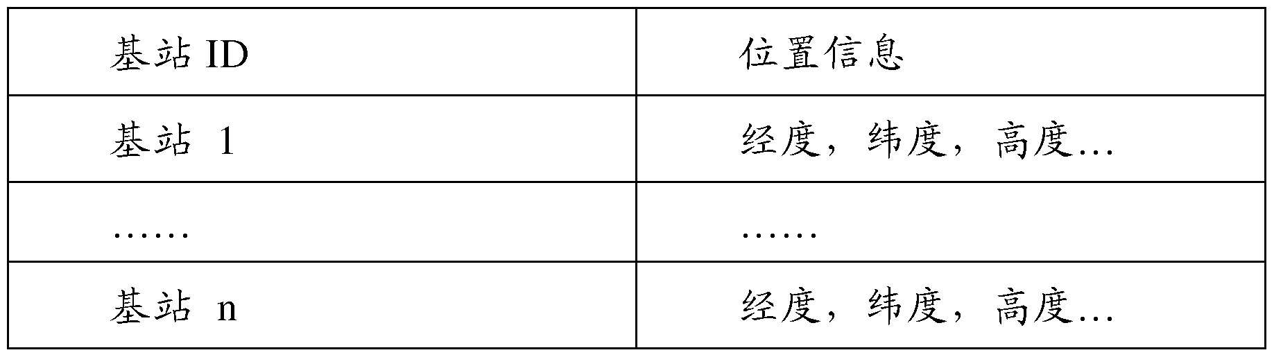
上述 LPN 小区的位置部署信息可以是直接保存在基站和 /或基站的 后台设备中的, 和 /或是保存在一个专门的服务器中, 基站在需要位置信 息时, 通过查询该专门服务器获得。 当 LPN小区的位置部署信息保存在基站和 /或基站的后台设备中时 , 其中涉及的 LPN小区包括该基站覆盖范围内的 LPN小区, 或者包括覆 盖范围内的 LPN小区和相邻的 LPN小区。基站之间可以通过 X2口交互 位置信息, 如当新增一 LPN小区后, 新增 LPN小区基站可以通过向宏 小区基站发送 X2 SETUP REQUEST消息, X2 SETUP RESPONSE消息, 或者 X2 ENB configuration update消息来协助更新和完善 LPN小区基站 的位置信息。 上述 X2 SETUP REQUEST消息的内容可以如下表所示:
IE/Group Name Presence Range IE type Semantics Criticality Assigned and description Criticality reference
Message Type M 9.2.13 YES reject
Global eNB ID M 9.2.22 YES reject
Served Cells 1 to Complete YES reject maxCellineNB list of cells
served by
the eNB
>Served Cell Information M 9.2.8
>Neighbour Information 0 to
maxnoofNeighb
ours
»Position information 0 Position
information
上表中 Served Cell Information信元可以用于携带基站位置信息,该 信元的内容可以如下:

served by
the eNB
>Served Cell Information M 9.2.8
>Neighbour Information 0 to
maxnoofNeighb
ours
»Position information 0 Position
information
可选的, 基站还可以通过收集 UE的测量报告, 根据测量报告中包 括的邻区位置信息辅助维护其覆盖范围内或相邻的 LNP 小区的位置信 息, 如加入新的 LNP小区位置部署信息等。 具体地, 如图 5所示, 本实施例在具体实施时, 包括如下步骤: 步骤 501、 宏小区基站获取 UE的位置信息和宏小区覆盖范围内的 LPN小区信息。
本步骤中也可以是宏小区基站获取 UE的位置信息, 以及, 宏小区 覆盖范围内和与宏小区相邻的 LPN小区位置信息。
如图 6所示, 为本实施例的一种示例性应用场景。在该场景下, LTE 宏小区 1部署在频率 1上, LPN小区 2, 如图中的 LOMO小区部署在该 宏小区覆盖范围内的频率 2上, 该 LOMO小区基站为图中的 WIFI AP。 在 LTE宏小区(以下筒称宏小区 )基站中保存了 WIFI AP的 ID、 LOMO 小区 2的 ID以及 WIFI AP的位置信息。 本实施例以这里保存的位置信 息包括经度、 维度、 高度和覆盖半径为例进行阐述。
本步骤中,可以是宏小区基站周期性发起对 UE的定位,如 OTDOA 定位来获取 UE的位置信息。 也可以是终端周期性地向宏小区基站上报 自己的位置信息, 如具有 GPS功能的终端周期性通过 GPS功能获取自 己位置信息后, 上报给基站。
步骤 502、 宏小区基站根据 UE的位置信息和自身中存储的 LPN小 区的位置信息, 监控 UE是否靠近 LPN小区。
本步骤中, 判断 UE是否靠近 LPN小区, 即为判断 UE是否进入该 LPN 小区的覆盖范围, 或者是否与该 LPN 小区的覆盖范围在设定门限 内。 上述覆盖范围根据经度、 维度、 高度和覆盖半径计算。
步骤 503、监控到 UE靠近 LPN小区后,宏小区基站通过 RRC专用 信令通知 UE靠近 LPN小区,该信令中携带靠近指示,靠近指示中包括, UE靠近的 LPN小区的 PCI和 /或 GCI, 或者进一步包括: 靠近小区的类 型、 靠近小区归属的基站节点的 ID、 靠近小区归属的基站节点的类型中 的任意一项或多项。
本步骤中, 基站也可以通过发送给 UE 的介质访问控制控制信令 ( Media Access Control Control element, MAC CE )携带上述靠近才旨示。
步骤 504、 UE接收包括靠近指示的信令, 根据信令中的靠近指示启 动对靠近的 LPN小区的测量。 这里测量的参数包括: 小区的信号强度和 /或信号质量。
本步骤中, 如果终端对 LPN 小区进行测量的射频是独立的射频, UE开启该 LPN小区对应的射频, 对这个 LPN小区的测量。 如果终端对 LPN小区进行测量的射频是和其他小区是共享的射频, 则 UE移动中心 频点, 实现对其他小区和这个 LPN小区的测量; 和 /或 UE在已打开的射 频上启动时间间隙 (GAP ) 测量该 LPN小区。 步骤 505: UE对测量的 LPN小区的信号强度和 /或信号质量进行监 测, 当监测到信号强度和 /或信号质量满足接入条件时, UE接入测量的 LPN小区。 本步骤中,接入条件为 LPN小区的信号强度和 /或信号质量满足 UE 正常业务通信的要求。 具体地, UE 中设定信号强度门限和 /或信号质量 门限, 当信号强度满足信号强度门限和 /或信号质量满足信号质量门限 时, 则信号强度和 /或信号质量满足 UE正常通信的要求。 具体的门限取 值可以为 -65dbm 本步骤中, 如果 LPN小区对应的射频是独立的射频, 则 UE接入测 量的 LPN小区为 UE直接在该 LPN小区对应的射频上接收数据; 否贝 ij ,
UE 通过向宏小区基站 (即源基站)发送测量报告发起异频或异系统切 换流程接入 LPN小区,具体的切换流程可以参考 3GPP协议 36.300中提 供的切换方案实现。
此外, UE接入 LPN小区后, 可以断开与宏小区的连接, 也可以保 持与宏小区的连接。 在保持与宏小区的连接的情况下, 可以是 UE 通知宏基站其接入 LPN小区后, 宏基站把 UE的所有业务都切换到 LPN小区, 或者宏基站 将 UE的部分业务都切换到 LPN小区。 具体地, UE接入 LPN小区后, 保持和源小区的信令连接, 并发送一个信令告知宏基站, 宏基站可以根 据 UE业务的特性和 /或宏基站的负荷情况, 来决定是把 UE的所有业务 都切换到 LPN小区还是把 UE的部分业务切换到 LPN小区。 具体业务 特性的选择和负荷门限的确定根据网络的具体情况确定。 如, 银行业务 等安全性要求比较高的业务, 依然在 LTE网络中传送; 而上网, 游戏等 业务, 可以在这 LPN小区内发送。
在保持与宏小区的连接的情况下, 也可以是由终端向用户提供人- 机界面供用户选择将 UE的所有业务都转移到 LPN小区, 还是把 UE的 部分业务转移到 LPN 小区, 此后终端根据用户的选择与宏基站和 LPN 小区基站通信进行业务切换。
步骤 506、 LPN小区基站获取终端的位置信息, 并根据 UE的位置 信息和自己中存储的 LPN小区位置信息, 监控 UE是否离开 LPN小区。
LPN小区基站中会保存该 LPN小区的位置部署信息,位置部署信息 的具体内容, 以及本步骤的具体实现参考步骤 501和步骤 502, 本步骤 中离开 LPN小区的条件与靠近 LPN小区的条件相反, 即到达 LPN小区 的覆盖范围边界, 或者在覆盖范围内距离边界设定距离。
步骤 507、 LPN小区基站监控到 UE离开 LPN小区后, 向 UE发送 离开指示。
上述离开指示可以通过 RRC专用信令或者 MAC CE携带, 离开指 示的具体内容可以包括: 离开的 LPN小区的 PCI和 /或 GCI。
步骤 508、 UE接收到离开指示后, 根据指示中的 PCI和 /或 GCI停 止对 LPN小区的测量并断开与 LPN小区的连接。
具体地, 本步骤中, 如果 LPN小区对应的射频是独立的射频, UE 就直接关闭在这个该 LPN 小区对应的射频上接收数据和测量; 否则, UE通过向 LPN小区基站 (即源基站 )发送测量报告发起异频或异系统 切换流程切换到宏小区, 并停止对 LPN小区的测量。 具体的切换流程可 以参考步骤 505实现。 在本实施例中, 可替换地, 步骤 503中, 在监控到 UE靠近 LPN小 区后, 宏小区基站也可以直接下发测量控制信息给 UE, 启动 UE对靠近 的 LPN 小区的测量。 测量控制信息中携带测量对象信息, 如小区 CPI 或 CGI, 或者进一步包括测量量和 /或测量上报配置信息。 则在步骤 404 中, UE接收到测量控制信息后, UE就根据测量控制信息启动对靠近的 LPN小区的测量, 如果测量控制信息中包括了测量量, 则 UE根据该测 量控制信息中的测量量如信号强度和 /或信号质量, 进行测量; 否则, 与 本实施例前述部分相同地, UE测量上述 LPN小区的信号强度和 /或信号 质量。 对应地, 在步骤 507中, LPN小区基站监控到 UE离开 LPN小区 后, 可以向 UE发送停止测量指示, 该指示中包括停止测量的对象, 即 LPN小区的 CGI或 CPI; 则在步骤 508中, UE根据测量停止指示停止 对 LPN小区的测量并发起切换。 本实施例中, 可替换地, 步骤 505中, 当监测到信号强度和 /或信号 质量满足接入条件时, UE将测量的 LPN小区的信号强度、 信号质量和 测量事件中的任意一项或多项报告给宏小区基站, 宏小区基站根据 UE 上报的信息确定是否让 UE接入靠近的 LPN小区, 当确定让 UE接入靠 近的 LPN小区后, 发送消息通知 UE, UE接收到通知后接入 LPN小区。 本较佳实施例中, 通过对终端与 LPN小区的位置信息的比较, 确定 是否启动终端对 LPN小区的测量, 一方面无需终端不断搜索 WIFI热点 小区, 节省了终端的耗电; 另一方面, 由于对 LPN小区的测量不考虑宏 小区的信号质量, 在宏小区信号质量很好的情况下, 也能够根据位置信 息启动对 LPN小区的测量, 从而提高了测量的及时性, 为 LPN小区更
加有效地分流宏小区终端提供了可能性。 进而, 由于在 LPN小区信号质 量能够满足终端业务通信的情况下, 即将终端接入到 LPN小区, 相对于 现有技术中在宏小区与 LPN 小区信号质量达到一定差别后才将终端接 入到 LPN小区的方案, 终端接入 LPN小区的可能性大大提高, 从而更 加有效地实现了 LPN小区对宏小区的分流。 示例性较佳实施例 2:
本实施例中, 由终端通过宏小区基站获取网络侧数据库中存储的 LPN小区位置信息, 并将其与自己的位置信息进行比较, 确定是否启动 对 LPN小区的测量, 并在满足接入条件时, 终端接入 LPN小区, 从而 实现更加有效地分流宏小区中的终端。
如图 7所示, 本实施例在实现过程中, 包括如下步骤: 步骤 701、 宏小区基站在系统广播消息中, 广播全部或者部分本宏 小区覆盖下的 LPN小区位置信息, 或者进一步广播相邻的 LPN小区的 位置信息。 步骤 702、 UE获取上述系统广播消息中的 LPN小区的位置信息, 并通过定位技术获取自己的位置信息, 根据自己的位置信息和从基站的 广播消息里获得 LPN小区的位置信息进行比较,监控自己是否靠近某个 LPN小区。
具体的比对方案参考前述步骤 502实现。 区别在于, 本步骤中, 如 果管波消息中包括多个 LPN小区的位置信息, 则 UE需要将自己的位置 信息逐个与各 LPN小区的位置信息进行比较。 步骤 703、 UE监控到自己靠近某个 LPN小区后, 对该 LPN小区的 信号强度和 /或信号质量进行测量。
本步骤中, UE对该 LPN小区的信号强度和 /或信号质量进行测量的 方案参考前述步骤 504实现。
此后的步骤 704与前述步骤 505相同, 并且类似地, 也可以采用上 一示例性较佳实施例中步骤 505的替换步骤。
步骤 705、 UE获取自己的位置信息, 根据获取的位置信息和接入的 LPN小区的位置信息进行比较, 监控自己是否离开该 LPN小区。
本实施例中, UE可以实时地通过自身的 GPS单元获取自身的位置 信息, 也可以周期发起网络定位, 如发起 OTDOA, 获取自身的位置信
步骤 706、 UE监控到自己离开 LPN小区后, 停止对 LPN小区的测 量, 并断开与 LPN小区的连接。
本步骤中具体停止测量以及断开连接的方案, 可以参考前一示例性 较佳实施例中的步骤 508实现。
可替换地, 本实施例步骤 703中, UE监控到自己靠近某个 LPN小 区后, 也可以不直接启动对 LPN小区的测量, 而是将靠近某个 LPN小 区的信息通过信令告知宏小区基站。 宏小区基站收到该信令后, 为 UE 配置测量控制信息, 并下发给 UE, 启动 UE对靠近的 LPN小区的测量。 测量控制信息中携带测量对象信息, 如小区 CPI或 CGI, 或者进一步包 括测量量和 /或测量上报配置信息。 UE接收到测量控制信息后, UE就根 据测量控制信息启动对靠近的 LPN小区的测量,如果测量控制信息中包 括了测量量, 则 UE根据该测量控制信息中的测量量如信号强度和 /或信 号质量, 进行测量; 否则, 与本实施例前述部分相同地, UE 测量上述 LPN小区的信号强度和 /或信号质量。 对应地, 在步骤 706中, UE监控 到离开 LPN小区后, 可以向 LPN小区发送信令, 将离开该 LPN小区的 信息通过信令告知 LPN小区基站, 则 LPN小区基站向 UE发送停止测 量指示, 该指示中包括停止测量的对象, 即 LPN小区的 CGI或 CPI; 则 UE根据测量停止指示停止对 LPN小区的测量并断开与 LPN小区的连 接。
本较佳实施例中, 通过对终端与 LPN小区的位置信息的比较, 确定 是否启动终端对 LPN小区的测量, 一方面无需终端不断搜索 WIFI热点 小区, 节省了终端的耗电; 另一方面, 由于对 LPN小区的测量不考虑宏 小区的信号质量, 在宏小区信号质量很好的情况下, 也能够根据位置信 息启动对 LPN小区的测量, 从而提高了测量的及时性, 为 LPN小区更
加有效地分流宏小区终端提供了可能性。 进而, 由于在 LPN小区信号质 量能够满足终端业务通信的情况下, 即将终端接入到 LPN小区, 相对于 现有技术中在宏小区与 LPN 小区信号质量达到一定差别后才将终端接 入到 LPN小区的方案, 终端接入 LPN小区的可能性大大提高, 从而更 加有效地实现了 LPN小区对宏小区的分流。 示例性较佳实施例 3: 本示例性较佳实施例中, 部署一个和 LPN小区基本同覆盖(本申请 文件中所提及的基本同覆盖是指第三小区的覆盖面积等于或略大于 LPN 小区, 如覆盖半径比在 1 :1至 1.1:1之间)的第三小区, 该第三小区的频 率与宏小区频率相同, 从而接入宏小区的终端可以直接接收到第三小区 的信号。
上述第三小区可以是一个实际的 LTE 小区, 也可以是一个虚拟小 区。 虚拟小区归属的基站在虚拟小区上仅发送同步信令和系统消息, 不 进行业务数据的调度。 如, 没有用于业务数据调度的 PDCCH和没有用 于发送下行业务数据的 PDSCH的发送。 第三小区的 PCI取自特定的一 组或多组第三小区 PCI。
UE中可以预先存储特定的第三小区 PCI组信息,也可以是 UE通过 接收宏小区基站的系统广播消息获取特定的第三小区 PCI组信息。当 UE 根据探测到的同步信令推出的 PCI属于这个特定的第三小区 PCI组时, 可以判断出存在一个第三小区, 从而异频率上有个与第三小区同覆盖的 LPN小区部署。 还可以进一步通过推出的 PCI, 确定出是具体哪个频率 上有 LPN小区部署, 即确定 LPN小区的频率信息。 本实施例中, 可以通过单独放置一基站的方式部署第三小区; 也可 以通过在 LPN 小区归属的基站上另外布置一个射频单元的方式部署第 三小区。
图 8示出了部署的第三小区为 LTE小区的一种场景,其中第三小区 为通过 WIFI AP部署的 LTE小区 3、宏小区为宏 LTE小区 1、 LPN小区 为通过 Pico AP部署的 LTE-LoMo小区 2。 图 8中, 通过 WIFI AP部署
的也可以是 LTE-LoMo小区 2, 而通过 Pico AP部署的为 LTE小区 3。 图 9示出了部署的第三小区为虚拟 LTE小区的一种场景,与图 8的 区别仅在于, 部署的第三小区为 LTE虚拟小区 3。 如图 10所示,本示例性较佳实施例在具体实现过程中,其流程具体 包括如下步骤: 步骤 1001、 接入宏小区的 UE进行同频邻区测量时, 探测是否获取 了第三小区的 PCL
具体地, 本步骤中, UE探测获取 PCI, 可以是 UE通过同频邻区测 量接收同频邻区的同步信令, 再根据接收的同步信令中的信息推导出 PCI。 具体根据同步信令推到 PCI 的方法为本领域技术人员所公知, 这 里不再赘述。
本步骤中, 接入宏小区的 UE判断探测到的 PCI是否取自特定的第 三小区 PCI组, 即是否属于特定的第三小区 PCI组, 即可以判定探测到 的 PCI对应的小区是否为第三小区, 如果探测到的 PCI对应的小区为第 三小区, 则可以确定终端靠近了第二小区。 步骤 1002、 探测到了第三小区的 PCI后, 对 LPN小区进行测量, 即对 LPN小区的信号强度和 /或信号质量进行测量。 本步骤中, 可以是 UE自行对 LPN小区进行测量, 如直接在所支持 的、 与第一小区异频的全部频率上进行测量, 或者根据自身中存储的信 息获取 LPN小区的频段信息, 再根据频段信息进行测量, 具体的实现方 案参考上述步骤 102中的相关描述。 UE对 LPN小区的信号强度和 /或信 号质量进行测量的具体实现方案参考上述步骤 504。
本步骤中, UE也可以不直接启动对 LPN小区的测量, 而是在探测 到了第三小区的 PCI后, 发送靠近指示给宏小区基站后, 由宏小区基站 为 UE配置对 LPN小区的测量配置信息,从而启动 UE对 LPN小区的测 量。 具体的实现方案参考上述步骤 102中的相关描述, 以及上述步骤这 里不再赘述。
步骤 1003、 UE对测量的 LPN小区的信号强度和 /或信号质量进行监
测, 当监测到信号强度和 /或信号质量满足接入条件时, UE接入测量的 LPN小区。 本步骤的具体实现参考前述步骤 505实现, 这里不再赘述。 步骤 1004、 接入 LPN小区的终端监控到自己离开 LPN小区后, 停 止对 LPN小区的测量, 并断开与 LPN小区的连接。 本步骤中, 终端通过监控接入的 LPN 的小区信号强度和 /或信号质 量, 根据是否: 小区信号强度低于设定的信号强度门限值和 /或信号质量 低于设定的信号质量门限值, 确定自己是否离开了 LPN小区。 本步骤中具体停止测量以及断开连接的方案, 可以参考前述步骤 508实现, 这里不再赘述。 本较佳实施例中,通过终端对是否存在与 LPN小区基本同覆盖的第 三小区进行探测, 从而确定是否启动终端对 LPN小区的测量, 提供了多 小区覆盖重叠情况下的小区测量方案。 进而, 一方面无需终端不断搜索 WIFI热点小区, 节省了终端的耗电; 另一方面, 由于对 LPN小区的测 量不考虑宏小区的信号质量, 在宏小区信号质量很好的情况下, 也能够 根据基本同覆盖的第三小区信息启动对 LPN小区的测量,从而提高了测 量的及时性, 为 LPN小区更加有效地分流宏小区终端提供了可能性。 进 而, 由于在 LPN小区信号质量能够满足终端业务通信的情况下, 即将终 端接入到 LPN小区, 相对于现有技术中在宏小区与 LPN小区信号质量 达到一定差别后才将终端接入到 LPN小区的方案, 终端接入 LPN小区 的可能性大大提高, 从而更加有效地实现了 LPN小区对宏小区的分流。 示例性较佳实施例 4: 本示例性较佳实施例中, 与上一示例性较佳实施例相同的是, 也部 署一个和 LPN小区 (即第二小区)基本同覆盖的第三小区。 第三小区的 具体部署方式参考上一示例性较佳实施例实现即可。 此外, 本示例性较佳实施例中, 还在网络侧保存第三小区与 LPN小 区的位置部署的关联信息 (即 LPN小区和第三小区的关联关系) 。 网络侧保存的上述 LPN小区与第三小区的关联信息,可以入下表所
关联对象 关联关系信息
小区 2, 小区 3 同覆盖
小区 4, 小区 5 同覆盖
小区 7, 小区 9 相邻
示。该关联关系可以是直接保存在宏小区基站和 /或宏小区基站的后台设 备中的, 和 /或是保存在一个专门的服务器, 如操作管理维护系统
( Operation Administration and Maintenance , OAM )服务器中 , 宏小区 基站在需要关联信息时, 通过查询该专门服务器获得。
LPN 小区与第三小区的关联信息中涉及的 LPN小区包括宏小区覆 盖范围内的 LPN小区, 或者包括宏小区覆盖范围内的 LPN小区和宏小 区相邻的 LPN小区。 基站之间可以通过 Χ2口交互小区位置关联信息(即上述 LPN小区 与第三小区的关联信息) , 如当新增一 LPN小区和 /或新增一第三小区 后, 新增小区所属的基站可以通过向宏小区基站(即, 第一小区的基站) 发送 Χ2 SETUP REQUEST消息, X2 SETUP RESPONSE消息, 或者 X2 ENB configuration update消息来协助更新和完善 LPN小区的信息和 /或 上述第三小区的信息, 这里的信息可以是位置信息, 则宏小区基站可以 根据接收的 LPN 小区的位置信息和第三小区的位置信息确定两小区关 联, 从而存储 LPN小区与第三小区的关联信息。 或者是上述新增小区的基站直接通过 X2口告知 LPN小区和第三小 区关联的信息给宏小区基站。 具体地, 新增小区的基站可以通过发送 X2 SETUP REQUEST消息, X2 SETUP RESPONSE消息, 或者 X2 ENB configuration update消息告知。 如图 10a所示, 本实施例具体实现过程中可包括如下步骤: 步骤 1011、 接入宏小区的 UE进行同频邻区测量时, 确定是否探测 到了第三小区的 PCI。
具体地, 本步骤中, UE探测获取 PCI, 可以是 UE通过同频邻区测 量接收同频邻区的同步信令, 再根据接收的同步信令中的信息推导出 PCI。 具体根据同步信令推到 PCI 的方法为本领域技术人员所公知, 这 里不再赘述。
UE中可以预先存储特定的第三小区 PCI组信息,也可以是 UE通过 接收宏小区基站的系统广播消息或专用信令获取特定的第三小区 PCI组 信息。 当 UE根据探测到的同步信令推出的 PCI属于这个特定的第三小 区 PCI组时, 可以判断出存在一个第三小区。
步骤 1012、 探测到了第三小区的 PCI后, UE发送靠近指示给宏小 区基站;
该靠近指示里包括第三小区 PCI。 步骤 1013、 宏小区基站收到靠近指示后, 根据自身保存的 LPN小 区和第三小区的关联关系, 获取对应的 LPN 小区信息, 并根据获取的 LPN小区信息确定测量配置信息。
上述 LPN 小区和第三小区的关联关系中, 第三小区的信息可以是 PCI信息, 也可以是第三小区的其他信息。 如果是第三小区的 PCI信息, 则宏小区基站直接根据靠近指示中的 PCI信息查询关联关系, 确定对应 的 LPN小区信息。 如果是第三小区的其他信息, 如 CGI, 则基站首先根 据靠近指示中的 PCI和自身中保存的第三小区信息获取对应的 CGI, 再 根据 CGI确定对应 LPN小区信息。
在确定对应的 LPN小区信息后, 基站根据该 LPN小区的频段 (关 联关系中的 LPN小区信息可以直接包括频段信息,也可以不包括频段信 息, 则基站根据 LPN小区信息, 如 CGI或 PCI和自身中保存的 LPN小 区信息与频段的对应关系确定频段信息)为 UE配置对 LPN小区的测量 配置信息, 从而启动 UE对 LPN小区的测量, 后续 UE根据测量配置信 息启动测量,接入第二小区的方案参考前述实施例实现, 这里不再赘述。
示例性较佳实施例 5:
本示例性较佳实施例中, 与上一示例性较佳实施例相同, 也部署一
个和 LPN小区 (即第二小区)基本同覆盖的第三小区, 并在网络侧保存 第三小区与 LPN小区的位置部署的关联信息 (即 LPN小区和第三小区 的关联关系) 。 这部分方案的具体实现参考上一示例性较佳实施例, 这 里不再赘述。
如图 10b所示, 本示例性较佳实施例在实现过程中包括如下步骤: 步骤 1021、 宏小区基站 (即, 第一小区的基站)给 UE配置周期性 测量配置信息;
周期性测量配置信息包括测量的频段、上报周期, 以及切换迟滞等。 这里测量的频率为宏小区的频段, 也即第三小区的频段。
步骤 1022、 接入宏小区的 UE根据上述周期性测量配置信息进行同 频邻区测量, 并将测量的结果周期性上报。
步骤 1023、 宏小区基站收到 UE的测量报告后, 如果报告中有第三 小区的信息,基站则根据自身保存的第三小区与 LPN小区的位置部署的 关联信息, 获取 LPN小区信息, 并根据获取的 LPN小区信息确定的测 量配置信息, 并配置给 UE, 以启动 UE对 LPN小区的测量。
后续 UE根据测量配置信息启动测量, 接入第二小区的方案参考前 述实施例实现, 这里不再赘述。 本步骤中, 基站中可以配置第三小区信息的集合, 当测量报告中的 第三小区的信息属于该集合时, 确定存在第三小区, 进而可以根据该第 三小区信息查询关联关系, 获取对应的 LPN小区信息。
基站中也可以不配置第三小区信息的集合, 则基站接收到测量报告 后, 查询上述关联关系中是否包括测量报告中上报的小区信息, 如果包 括, 则进而根据该小区信息确定关联的 LPN小区; 否则, 认为 UE没有 探测到第三小区, 可以不对该测量报告进行处理。 上述第三小区的信息可以是 PCI, 也可以是 CGI或其他信息。
上述示例性较佳实施例 4和 5中, 通过在网络侧存储第二小区和第 三小区的关联关系, 从而宏基站在确定出 UE探测到了第三小区后, 即
UE 到达了第三小区的覆盖范围后, 根据第三小区信息获取关联的第二 小区, 并向 UE下发测量配置信息, 从而启动 UE对第二小区的测量, 提供了多小区覆盖重叠情况下的小区测量方案。 进而, 一方面无需终端 不断搜索 WIFI热点小区, 节省了终端的耗电; 另一方面, 由于对 LPN 小区的测量不考虑宏小区的信号质量,在宏小区信号质量很好的情况下, 也能够根据基本同覆盖的第三小区信息启动对 LPN小区的测量,从而提 高了测量的及时性,为 LPN小区更加有效地分流宏小区终端提供了可能 性。 进而, 由于在 LPN小区信号质量能够满足终端业务通信的情况下, 即将终端接入到 LPN小区, 相对于现有技术中在宏小区与 LPN小区信 号质量达到一定差别后才将终端接入到 LPN小区的方案,终端接入 LPN 小区的可能性大大提高,从而更加有效地实现了 LPN小区对宏小区的分 流。 上述各方法实施例中, 相关部分的方案可以在各实施例间参考或替 换实现。 本领域普通技术人员可以理解, 实现上述方法实施方式中的全部或 部分步骤是可以通过程序来指令相关的硬件来完成, 上述的程序可以存 储于计算机可读取存储介质中, 该程序在执行时, 可以包括前述本发明 基于 MIP技术的通信方法各个实施方式的内容。这里所称得的存储介质, 如: ROM/RAM、 磁碟、 光盘等。 本发明实施例还提供了一种终端, 如图 11所示, 该终端包括: 探测单元 111 , 用于探测第三小区的信令, 上述第三小区为与上述 终端接入的第一小区同频的小区; 测量单元 112,用于在上述探测单元 111探测到第三小区的信令后, 对第二小区进行测量, 上述第二小区为与第三小区相关联的, 且与第一 小区异频的小区。 上述第一小区可以为宏小区, 则上述第二小区为上述宏小区覆盖区 域内的小区或为与上述宏小区相邻的小区。 上述第二小区与第三小区相关联可以为: 上述第二小区与上述第三
小区同覆盖, 或者上述第三小区的覆盖范围包括上述第二小区的覆盖范 围;
上述对第二小区进行测量可以包括: 根据上述探测到的第三小区的 信令,确定上述终端靠近了上述第二小区, 并对上述第二小区进行测量。
如图 12所示, 上述终端进一步可以包括: 存储单元 113 , 用于存储特定的第三小区 PCI组的信息;
则上述探测单元 111具体可以用于, 对上述第一'■!、区的同频邻区进 行测量, 根据测量中探测到的同步信令, 推出发送同步信令的小区的物 理小区标识 PCI, 并确定该 PCI是否属于上述存储单元 113保存的特定 的第三小区 PCI组。
上述测量单元 112具体可以用于, 在上述探测单元 111探测到第三 小区的信令后, 在上述终端支持的全部异频频率上进行测量。 如图 13所示, 上述终端中进一步可以包括: 存储单元 113 , 保存 特定的第三小区 PCI组与第二小区频率信息的对应关系; 则上述探测单元 111具体可以用于, 对上述第一'■!、区的同频邻区进 行测量, 根据测量得到的同步信令, 推出发送同步信令的小区的物理小 区标识 PCI, 并确定该 PCI是否属于上述存储单元 113 保存的特定的 第三小区 PCI组;
上述测量单元 112具体可以用于, 在上述探测单元 111确定推出的 PCI属于上述存储单元 113 保存的特定第三小区 PCI组后, 根据上述 存储单元 113 存储的对应关系获取上述 PCI属于的特定的第三小区 PCI 组对应的第二小区频率信息,并根据获取的第二小区频率信息进行测量, 或者, 通过所述终端中的收发单元向所述第一小区所属的基站发送所述 第二小区频率信息, 并通过所述终端中的收发单元接收所述第一小区所 属的基站反馈的、 所述第一小区所属的基站根据所述第二小区频率信息 确定的测量配置信息, 并根据所述接收的测量配置信息进行测量。
如图 14所示, 上述终端进一步可以包括:
靠近指示生成单元 114, 用于在上述探测单元 111探测到第三小区 的信令后, 生成靠近指示; 收发单元 115 ,用于向上述第一小区所属的基站发送上述靠近指示, 并接收上述第一小区归属的基站反馈的测量配置信息, 上述测量配置信 息包括对上述第一小区覆盖范围内的和 /或相邻的全部异频小区的测量 配置信息;
则上述测量单元 112具体可以用于, 在所述探测单元 111探测到第 三小区的信令后,根据上述收发单元 115接收的测量配置信息进行测量。
如图 15所示, 上述终端进一步可以包括: 靠近指示生成单元 114 ,用于在上述探测单元 111确定推出的 PCI 属于上述特定的第三小区 PCI组后, 生成包括上述推出的 PCI的靠近指 示;
收发单元 115 , 用于向上述第一小区所属的基站发送上述靠近指 示, 并接收上述第一小区归属的基站反馈的测量配置信息, 上述测量配 置信息包括上述 PCI对应小区的测量配置信息,即包括基站根据上述 PCI 确定的第二小区、 的测量配置信息;
则上述测量单元 112具体可以用于, 在所述探测单元 111探测到第 三小区的信令后, 根据上述收发单元 115' 接收的测量配置信息进行测 量。
上述存储单元 113进一步可以用于, 保存特定的第三小区 PCI组与 第二小区频率信息的对应关系; 如图 16所示, 上述终端中进一步可以包括: 靠近指示生成单元 114 " ,用于在上述探测单元 111确定推出的 PCI 属于上述特定的第三小区 PCI组后, 根据上述存储单元 113 (或 113 ) 存储的对应关系, 获取上述推出的 PCI所属的特定第三小区 PCI组对应 的第二小区的频率信息, 并生成包括上述获取的第二小区频率信息的靠 近指示;
收发单元 115 " , 用于向上述第一小区所属的基站发送上述靠近指 示, 并接收上述第一小区归属的基站反馈的测量配置信息, 上述测量配 置信息包括上述靠近指示中的第二小区频率信息对应测量配置信息; 则上述测量单元 112具体用于, 在所述探测单元 111探测到第三小 区的信令后, 根据上述收发单元 115 " 接收的测量配置信息进行测量。 上述存储单元 113 (或 113 ) 中存储的信息, 可以是终端中预先存 储的, 也可以是通过收发单元 115 (或 115 、 115 " )从网络侧获取的, 具体的获取方案参考上述第一种方法实施例中的相关描述。
如图 17所示, 上述终端中进一步可以包括: 接入单元 116, 用于根据测量单元 112对第二小区测量的结果, 在 确定出第二小区的信号质量能够满足上述终端的业务通信后, 将上述终 端接入到上述第二小区。 上述接入单元 116进一步可以用于断开上述终端与上述第一小区的 信令连接, 或者, 进一步用于保持上述终端与上述第一小区的信令连接。
本实施例中, 所涉及的具体的终端如何接入小区、 如何进行测量的 方案, 均可以参照前述方法实施例的对应方案实现。
如图 18所示, 本发明实施例提供的一种基站, 包括: 第一射频单元 181 , 用于形成第二小区;
第二射频单元 182, 用于形成与上述第二小区异频的第三小区; 处理单元 183 , 用于根据第三小区 PCI组中的 PCI生成同步信令, 并通过上述第二射频单元 182在第三小区上发送上述生成的同步信令, 以使得在第三小区覆盖范围内的终端通过接收上述同步信令推出属于上 述特定第三小区 PCI组中的 PCI。 这里的第三小区 PCI组, 即其他实施 例中提及的特定第三小区 PCI组, 两者含义相同。 上述处理单元 183具体可以用于在所述第三小区上仅发送同步信令 和系统消息。 具体这里所涉及的仅发送的同步信令和系统消息的进一步 实现, 参考前述实施例中涉及虚拟小区的相关描述。
上述第二射频单元 182用于形成的第三小区可以与上述第二小区同 覆盖, 或上述第三小区的覆盖范围包括上述第二小区的覆盖范围。 上述处理单元 183进一步可以用于,通过所述基站中的通信单元 183 向第一小区基站发送所述第二小区和第三小区的信息; 或者进一步可以用于, 通过所述基站中的通信单元 183向第一小区 基站发送所述第二小区和所述第三小区相关联的信息。 所述处理单元 183具体可以用于生成包括所述向第一小区基站发送 的信息的 X2 SETUP REQUEST消息、 X2 SETUP RESPONSE消息、 或 者 X2 ENB configuration update消息, 并通过所述通信单元向所述宏小 区基站发送所述消息。 上述第一小区与上述第三小区同频, 上述第一小区与上述第二小区 异频; 上述第二小区与上述第三小区相关联。 上述第一小区可以为宏小区, 则上述第二小区为上述宏小区覆盖区 域内的小区, 或为与上述宏小区相邻的小区。 上述第二小区与第三小区相关联可以为: 上述第二小区与上述第三 小区同覆盖, 或者上述第三小区的覆盖范围包括上述第二小区的覆盖范 围。 本实施例中的第二小区和第三小区, 即为前述各方法及终端实施例 中的第二小区和第三小区, 相应地, 终端在第二小区上与网络侧交互的 方案, 在第三小区上与网络侧交互的方案, 在网络侧均可以由本实施例 中提供的基站执行; 类似地, 涉及到第二小区、 第三小区所归属的基站 与其他基站等网络设备交互的方案也可以由本实施例中提供的基站执 行。 上述终端实施例中, 通过部署与第二小区相关联, 与第一小区同频 的第三小区, 使得接入第一小区的终端通过探测第三小区的信令即可确 定是否存在第二小区, 从而终端可以及时对第二小区进行测量, 提供了 与现有技术不同的小区测量方案。 进而, 当上述方案应用于多小区覆盖 重叠场景时, 一方面, 上述方案由于无需持续的进行小区搜索, 降低了
UE 耗电量; 另一方面, 在第一小区为宏小区, 第二小区为低功率节点 小区情况下, 在宏小区信号较好时, 通过应用上述方案也能够启动对低 功率节点小区的测量, 启动测量不受宏小区信号影响, 使得低功率节点 小区对宏小区的分流更加快速有效。 如图 19所示, 本发明实施例提供的另一种基站, 包括: 射频单元 191 , 用于形成第一'■!、区; 广播单元 192, 用于在上述第一小区上广播特定的第三小区 PCI组 信息, 和 /或, 广播特定的第三小区 PCI组信息与第二小区的频率信息的 对应关系; 上述特定的第三小区 PCI组中的 PCI对应于上述第一小区同 频的第三小区, 上述第二小区为与上述第一小区异频, 且与上述第三小 区相关联的小区。 本实施例中的第一小区可以为宏小区, 则上述第二小区为上述宏小 区覆盖区域内的小区或为与上述宏小区相邻的小区。
上述第二小区与第三小区相关联可以为: 上述第二小区与上述第三 小区同覆盖, 或者上述第三小区的覆盖范围包括上述第二小区的覆盖范 围。 如图 20所示, 上述基站中进一步可以包括: 测量配置单元 193 , 用于通过射频单元接收来自上述第一小区的终 端的靠近指示, 根据上述靠近指示获取上述第一小区覆盖范围内的和 / 或相邻的异频小区的频率信息, 并根据获取的异频小区的频率信息确定 测量配置信息, 将上述测量配置信息在上述第一小区下发给上述终端; 或者用于, 接收来自第一小区的终端的、 包括第三小区 PCI的靠近 指示, 根据上述靠近指示和自身中存储的特定第三小区 PCI组与第二小 区频率信息的对应关系, 获取上述靠近指示中的第三小区 PCI对应的第 二小区频率信息, 并根据获取的第二小区频率信息确定测量配置信息, 将上述测量配置信息在上述第一小区下发给上述终端; 或者用于, 接收来自第一小区终端的、 包括第二小区频率信息的靠 近指示, 根据上述靠近指示中的第二小区频率信息确定测量配置信息,
将上述测量配置信息在上述第一小区下发给上述终端。 本实施例中的第一'■!、区或宏小区, 即为前述方法及终端实施例中的 第一'■!、区或宏小区, 前述方法及终端实施例中, 凡涉及到第一'■!、区或宏 小区归属的基站所执行的方案, 均可以由本实施例提供的基站执行。 本实施例提供了一种网络系统, 该网络系统可以包括: 第一基站, 用于形成第一小区;
第二基站, 用于形成与上述第一小区异频的第二小区;
第三基站, 用于形成与上述第二小区同覆盖的第三小区, 并在第三 小区上发送用于终端推出第三小区 PCI的同步信令, 上述第三小区与上 述第一小区同频, 上述 PCI为特定的第三小区 PCI组中的 PCI。
上述第二基站和第三基站可以为同一基站, 也可以为不同的基站。 上述第一小区可以是宏小区; 则上述第二基站用于形成与上述宏小 区异频的第二小区, 且上述第二小区在上述宏小区覆盖范围内, 或与上 述宏小区相邻。 上述第一基站进一步用于在上述第一小区上广播特定的第三小区
PCI组信息, 和 /或, 广播特定的第三小区 PCI组信息与第二小区的频率 信息的对应关系; 和 /或,
上述第一基站进一步用于, 在上述第一小区接收来自终端的靠近指 示,根据上述靠近指示获取上述第一小区覆盖范围内的和 /或相邻的异频 小区的频率信息,并根据获取的异频小区的频率信息确定测量配置信息, 将上述测量配置信息在上述第一小区下发给上述终端;
或者进一步用于, 在上述第一小区接收来自终端的、 包括第三小区
PCI 的靠近指示, 根据上述靠近指示和自身中存储的特定第三小区 PCI 组与第二小区频率信息的对应关系, 获取上述靠近指示中的第三小区
PCI 对应的第二小区频率信息, 并根据获取的第二小区频率信息确定测 量配置信息, 将上述测量配置信息在上述第一小区下发给上述终端;
或者进一步用于, 在上述第一小区接收来自终端的、 包括第二小区 频率信息的靠近指示, 根据上述靠近指示中的第二小区频率信息确定测 量配置信息, 将上述测量配置信息在上述第一小区下发给上述终端。
本实施例中, 所涉及的第一小区、 第二小区和第三小区均指前述方 法及终端实施例中的第一小区、 第二小区和第三小区, 则上述方法实施 例中各小区归属的基站所执行的方案, 均可以对应由本实施例中的第一 基站、 第二基站或第三基站执行。 上述基站及网络系统实施例中, 通过部署与第二小区相关联, 与第 一小区同频的第三小区, 使得接入第一小区的终端通过探测第三小区的 信令即可确定是否存在第二小区, 从而终端可以及时对第二小区进行测 量, 在网络侧支持了前述提供的与现有技术不同的小区测量方案。 进而, 当上述方案应用于多小区覆盖重叠场景时, 一方面, 上述方案由于无需 持续的进行小区搜索, 降低了 UE耗电量; 另一方面, 在第一小区为宏 小区, 第二小区为低功率节点小区情况下, 在宏小区信号较好时, 通过 应用上述方案也能够启动对低功率节点小区的测量, 启动测量不受宏小 区信号影响, 使得低功率节点小区对宏小区的分流更加快速有效。 如图 19a所示, 本发明实施例还提供了一种基站, 该基站包括: 存储单元 194, 用于存储第二小区与第三小区相关联的信息, 所述 第三小区与所述基站形成的第一小区同频, 所述第二小区与所述第一小 区异频;
收发单元 195 , 用于接收来自终端的第三小区标识信息, 所述终端 接入了所述第一小区; 测量配置单元 196, 用于根据所述存储单元 194存储的对应关系和 所述收发单元 195接收的第三小区标识信息, 获取与该第三小区关联的 第二小区信息,并生成针对该第二小区的测量配置信息下发给所述终端。 如图 19b所示, 上述图 19a所示的基站进一步可以包括: 通信单元 197 , 用于接收第二基站发送的所述第二基站所辖的第二 小区和第三小区的信息, 或者用于接收第二基站发送的所述第二基站所
辖第二小区和第三小区相关联的信息, 或者用于接收第二基站发送的所 述第二基站所辖的第二小区的信息和第三基站发送的所述第三基站所辖 的第三小区的信息; 处理单元 198 , 用于根据所述接收的信息生成所述第二小区与所述 第三小区相关联的信息, 并存储在所述存储单元 194中。 上述通信单元 197接收的信息可以携带在 X2 SETUP REQUEST消 息、 X2 SETUP RESPONSE消息、或者 X2 ENB configuration update消息 中。
如图 19c所示, 本发明实施例还提供了另一种基站, 该基站包括: 通信单元 197 , 用于接收第二基站发送的所述第二基站所辖的第二 小区和 /或第三小区的信息, 或者用于接收第二基站发送的所述第二基 站所辖第二小区和第三小区相关联的信息, 或者用于接收第二基站发送 的所述第二基站所辖的第二小区的信息和第三基站发送的所述第三基站 所辖的第三小区的信息;所述第三小区与所述基站形成的第一小区同频, 所述第二小区与所述第一小区异频; 处理单元 198 , 用于根据所述接收的信息生成所述第二小区与所 述第三小区相关联的信息, 并存储在存储单元 194中。 较佳地, 所述通信单元 197 接收的上述信息携带在 X2 SETUP REQUEST消息、 X2 SETUP RESPONSE消息、或者 X2 ENB configuration update消息中。 上述两个基站实施例中, 上述第一小区与上述第三小区同频, 上述 第一小区与上述第二小区异频; 上述第二小区与上述第三小区相关联。 上述第一小区可以为宏小区, 则上述第二小区为上述宏小区覆盖区 域内的小区, 或为与上述宏小区相邻的小区。 上述第二小区与第三小区相关联可以为: 上述第二小区与上述第三 小区同覆盖, 或者上述第三小区的覆盖范围包括上述第二小区的覆盖范 围。
通过上述两个基站实施例的方案, 基站获取了相关联的第二小区和 第三小区的信息, 并在自身中存储, 则后续可协助终端确定其接入的小 区是否存在相关联的小区, 或者可以协助接入第一小区的终端获取其能 够探测到的第三小区所关联的第二小区的信息, 使得终端可以对关联的 第二小区进行测量。 如图 21所示, 本实施例还提供了一种网络设备, 该网络设备包括: 监测单元 211 , 用于根据从第一小区归属的基站获取的第二小区位 置信息、 和接入上述第一小区的终端的位置信息, 监测上述终端是否靠 近第二小区; 测量启动单元 212, 用于在上述监测单元监测到上述终端靠近第二 小区时, 启动上述终端对上述靠近的第二小区的测量。 上述第一小区可以是宏小区, 则上述监测单元 211具体可以用于根 据从宏小区归属的基站获取的第二小区位置信息、 和接入上述宏小区的 终端的位置信息, 监测上述终端是否靠近第二小区。 上述网络设备可以为基站; 则上述监测单元 211具体用于, 获取上 述终端的位置信息, 并获取上述基站中保存的第二小区的位置信息, 根 据上述获取的终端位置信息和第二小区信息判断上述终端是否靠近第二 小区。
如图 22 所示, 在上述网络设备为基站时; 上述测量启动单元 212 可以包括: 通知消息生成单元 2121 , 用于根据上述监测单元 211判断出的上述 终端靠近第二小区的信息, 生成通知消息, 该通知消息用于通知上述终 端靠近的第二小区的信息;
收发单元 2122, 用于将上述通知消息生成单元 2121生成的通知消 息下发给上述终端, 以使得上述终端根据上述通知消息启动对上述靠近 的第二小区的测量; 或者, 如图 23所示, 上述测量启动单元 212可以包括:
测量配置信息配置单元 2123 ,用于根据上述监测单元 211判断出的 上述终端靠近第二小区的信息, 为上述终端配置测量配置信息; 收发单元 2122 , 用于将上述测量配置信息配置单元为上述终端配 置的测量配置信息下发给上述终端, 以使得上述终端根据上述配置的测 量配置信息启动对上述靠近的第二小区的测量。 上述网络设备也可以为终端; 则如图 24所示,上述终端进一步可以 包括: 收发单元 213 , 用于接收上述第一小区归属的基站发送的第二小区 的位置信息; 上述监测单元 211具体用于, 从上述收发单元 213获取上述第二小 区的位置信息, 并获取上述终端的位置信息, 根据上述获取的第二小区 的位置信息和自身的位置信息判断上述终端是否靠近第二小区。 上述收发单元 213具体可以用于接收上述第一小区归属的基站发送 的第一小区的系统广播消息, 上述系统广播消息中包括上述第二小区的 位置信息; 则上述监测单元 211具体可以用于, 从上述收发单元接收的系统广 播消息中获取上述第二小区的位置信息, 并获取上述终端的位置信息, 根据上述获取的第二小区的位置信息和上述终端的位置信息判断上述终 端是否靠近第二小区。
上述收发单元 213进一步可以用于: 接收上述第一小区归属的基站 发送的第一小区的系统广播消息, 该广播消息中包括上述靠近的第二小 区的频率信息; 则上述测量启动单元 212具体可以用于在上述监测单元 211监测到 上述终端靠近第二小区时, 根据上述收发单元 213接收的系统广播消息 中的第二小区的频率信息, 启动对上述靠近的第二小区的测量。 测量启 动单元 212启动对靠近的第二小区的测量具体可以是,测量启动单元 212 直接对小区的信号强度和 /或信号质量进行测量。 上述测量启动单元 212具体可以用于在上述监测单元 211监测到上
述终端靠近第二小区时, 生成向上述第一小区归属的基站发送的通知消 息, 该通知消息中包括上述终端靠近的第二小区的信息; 并根据收发单 元 213接收的测量配置信息启动对靠近的第二小区的测量; 则上述收发单元 213进一步可以用于, 向上述第一小区归属的基站 发送上述测量启动单元 212生成的通知消息, 并接收上述第一小区归属 的基站配置的上述靠近的第二小区的测量配置信息。 如图 25所示, 上述网络设备进一步可以包括: 接入单元 214, 用于在测量启动单元测量的上述靠近的第二小区的 信号质量能够满足上述终端的业务通信时, 控制上述终端通过上述收发 单元 213接入第一'■!、区。 上述接入单元 214进一步可以用于, 断开上述 UE与上述第一'■!、区 的信令连接, 或者保持上述 UE与上述第一小区的信令连接。 本实施例中, 通过对终端与第二小区的位置信息的比较, 确定是否 启动终端对第二小区的测量, 提供了与现有技术不同的小区测量方案。 进而, 当上述方案应用于多小区覆盖重叠场景时, 一方面, 上述方案由 于无需持续的进行小区搜索, 降低了 UE耗电量; 另一方面, 在第一小 区为宏小区, 第二小区为低功率节点小区情况下, 在宏小区信号较好时, 通过应用上述方案也能够启动对低功率节点小区的测量, 启动测量不受 宏小区信号影响, 使得低功率节点小区对宏小区的分流更加快速有效。 上述终端和网络设备中各个单元用于执行的方案的具体实现参考前 述各方法实施例。 虽然通过参照本发明的某些优选实施方式, 已经对本发明进行了图 示和描述, 但本领域的普通技术人员应该明白, 可以在形式上和细节上 对其作各种改变, 而不偏离本发明的精神和范围。
Claims
1、 一种小区测量方法, 其特征在于, 该方法包括: 接入第一小区的终端探测第三小区的信令; 在探测到第三小区的信令后, 对第二小区进行测量; 所述第一小区与所述第三小区同频, 所述第一小区与所述第二小区 异频; 所述第二小区与所述第三小区相关联。
2、 根据权利要求 1所述的方法, 其特征在于, 所述第一小区为宏小 区, 所述第二小区为所述宏小区覆盖区域内的小区或为与所述宏小区相 邻的小区。
3、 根据权利要求 1或 2所述的方法, 其特征在于, 所述第二小区与 第三小区相关联为: 所述第二小区与所述第三小区同覆盖, 或者所述第 三小区的覆盖范围包括所述第二小区的覆盖范围; 所述对第二小区进行测量包括:根据所述探测到的第三小区的信令, 确定所述终端靠近了所述第二小区或进入了第二小区的覆盖范围, 并对 所述第二小区进行测量。
4、 根据权利要求 1至 3中任一所述的方法, 其特征在于, 所述终端 中保存特定的第三小区物理小区标识 PCI组的信息;
所述终端探测第三小区的信令包括: 所述终端进行同频邻区测量, 根据测量中探测到的同步信令, 推出 发送所述同步信令的小区的 PCI, 并确定该 PCI是否属于所述保存的特 定的第三小区 PCI组,以确定探测到的同步信令是否为第三小区的信令。
5、 根据权利要求 1至 4中任一所述的方法, 其特征在于, 所述对第 二小区进行测量包括: 所述终端在本终端所支持的、 与第一小区异频的全部频率上进行测 量。
6、 根据权利要求 5所述的方法, 其特征在于, 所述终端在所支持的 全部异频频率上对第二小区进行测量包括:
终端判断是否需要启动 GAP, 如果是, 则根据 GAP在所支持的全 部异频频率上对第二小区进行测量, 并发送 GAP图样给网络侧; 否贝 |J , 直接在所支持的全部异频频率上对第二小区进行测量。
7、 根据权利要求 4所述的方法, 其特征在于, 所述终端中进一步保 存特定的第三小区 PCI组与第二小区频率信息的对应关系;
所述终端在探测到第三小区的信令后, 对第二小区进行测量包括: 所述终端在确定推出的 PCI属于特定的第三小区 PCI组后, 根据所 述对应关系获取所述 PCI属于的特定的第三小区 PCI组对应的第二小区 频率信息,
根据获取的第二小区频率信息进行测量, 或者, 向所述第一小区所 属的基站发送所述第二小区频率信息, 并接收所述第一小区所属的基站 反馈的、 所述第一小区所属的基站根据所述第二小区频率信息确定的测 量配置信息, 并根据所述接收的测量配置信息进行测量。
8、 根据权利要求 1至 4中任一所述的方法, 其特征在于, 所述对第 二小区进行测量之前进一步包括: 所述终端向所述第一小区所属的基站发送第三小区的信息或靠近指 示, 并接收所述第一小区归属的基站反馈的测量配置信息;
所述对第二小区进行测量包括: 根据所述接收的测量配置信息进行 测量。
9、 根据权利要求 8所述的方法, 其特征在于, 所述接收的测量配置 信息包括: 所述第一小区的基站接收到所述靠近指示后, 根据所述第一 小区覆盖范围内的和 /或相邻的异频小区的频率信息,确定的测量配置信
10、 根据权利要求 8所述的方法, 其特征在于, 所述靠近指示包括 所述终端探测到的第三小区的 PCI; 所述接收的测量配置信息包括: 所述第一小区的基站接收到所述靠 近指示后, 根据自身保存的第三小区 PCI组与第二小区频率信息的对应 关系, 以及所述靠近指示中的所述 PCI, 获取第二小区频率信息, 并根 据获取的第二小区频率信息确定的测量配置信息; 或者包括: 所述第一小区的基站接收到所述靠近指示后, 根据自身 中配置的小区关联关系表, 以及所述靠近指示中包括的所述 PCI, 确定 与第三小区关联的第二小区, 再根据所述确定的第二小区的频率信息, 确定的测量配置信息。
11、 根据权利要求 8所述的方法, 其特征在于, 所述发送的第三小 区的信息包括: 所述终端根据所述第一小区所属的基站下发的测量配置 信息、 进行同频邻区测量后, 周期性上报的测量报告; 则接收的第一小区所属的基站反馈的测量配置信息包括, 所述第一 小区所属的基站, 根据所述测量报告中的第三小区标识, 以及自身中配 置的小区关联关系表, 确定与第三小区关联的第二小区, 再根据所述确 定的第二小区的频率信息, 确定的测量配置信息。
12、 根据权利要求 1至 11中任一所述的方法, 其特征在于, 所述终 端启动对所述第二小区的测量后, 进一步包括: 当测量的所述第二小区的信号质量能够满足所述终端的业务通信 时, 所述终端接入到所述第二小区 。
13、 一种信息处理方法, 其特征在于, 该方法包括: 第一小区的基站接收第二基站发送的所述第二基站所辖的第二小区 和 /或第三小区相关联的信息, 或者接收第二基站发送的所述第二基站 所辖第二小区和第三基站所辖的第三小区相关联的信息, 或者接收第三 基站发送的所述第二基站所辖第二小区和第三基站所辖的第三小区相关 联的信息, 或者接收来自运营管理系统的第二小区和第三小区相关联的 信息; 所述第三小区与所述基站形成的第一小区同频, 所述第二小区与 所述第一小区异频; 根据所述接收的信息生成所述第二小区与所述第三小区相关联的信 息, 并存储所述关联的信息。
14、 根据权利要求 13所述的方法, 其特征在于, 所述接收的信息携 带在 X2 设置请求 SETUP REQUEST 消息、 X2 设置响应 SETUP RESPONSE消息、或者 X2基站配置更新 ENB configuration update消息 中。
15、 一种终端, 其特征在于, 该终端包括: 探测单元, 用于探测第三小区的信令, 所述第三小区为与所述终端 接入的第一小区同频的小区; 测量单元, 用于在所述探测单元探测到第三小区的信令后, 对第二 小区进行测量, 所述第二小区为与第三小区相关联的, 且与第一小区异 频的小区。
16、 根据权利要求 15所述的终端, 其特征在于, 所述终端进一步包 括: 存储单元, 用于存储特定的第三小区 PCI组的信息;
所述探测单元具体用于, 对所述第一小区的同频邻区进行测量, 根 据测量中探测到的同步信令, 推出发送同步信令的小区的物理小区标识 PCI, 并确定该 PCI是否属于所述存储单元保存的特定的第三小区 PCI 组。
17、 根据权利要求 15或 16所述的终端, 其特征在于, 所述测量单 元具体用于, 在所述探测单元探测到第三小区的信令后, 在所述终端支 持的、 与第一小区异频的全部频率上进行测量。
18、 根据权利要求 15所述的终端, 其特征在于, 所述终端中进一步 包括: 存储单元, 保存特定的第三小区 PCI组与第二小区频率信息的对 应关系;
所述探测单元具体用于, 对所述第一小区的同频邻区进行测量, 根 据测量得到的同步信令, 推出发送所述同步信令的小区的 PCI, 并确定 该 PCI是否属于所述存储单元保存的特定的第三小区 PCI组, 以确定探 测到的同步信令是否为第三小区的信令; 所述测量单元具体用于, 在所述探测单元确定推出的 PCI属于所述 存储单元保存的特定第三小区 PCI组后, 根据所述存储单元存储的对应 关系获取所述 PCI属于的特定的第三小区 PCI组对应的第二小区频率信
根据获取的第二小区频率信息进行测量, 或者, 通过所述终端中的 收发单元向所述第一小区所属的基站发送所述第二小区频率信息, 并通 过所述终端中的收发单元接收所述第一小区所属的基站反馈的、 所述第 一小区所属的基站根据所述第二小区频率信息确定的测量配置信息, 并 根据所述接收的测量配置信息进行测量。
19、 根据权利要求 15或 16所述的终端, 其特征在于, 所述终端进 一步包括: 靠近指示生成单元,用于在所述探测单元探测到第三小区的信令后, 生成靠近指示;
收发单元, 用于向所述第一小区所属的基站发送所述靠近指示, 并 接收所述第一小区归属的基站反馈的测量配置信息, 所述测量配置信息 包括对所述第一小区覆盖范围内的和 /或相邻的全部异频小区的测量配 置信息;
则所述测量单元具体用于, 在所述探测单元探测到第三小区的信令 后, 根据所述收发单元接收的测量配置信息进行测量。
20、 根据权利要求 16所述的终端, 其特征在于, 所述终端进一步包 括: 靠近指示生成单元, 用于在所述探测单元确定推出的 PCI属于所述 特定的第三小区 PCI组后, 生成包括所述推出的 PCI的靠近指示; 收发单元, 用于向所述第一小区所属的基站发送所述靠近指示, 并 接收所述第一小区归属的基站反馈的测量配置信息, 所述测量配置信息 包括所述基站根据所述 PCI确定的第二小区、 的测量配置信息; 则所述测量单元具体用于, 根据所述收发单元接收的测量配置信息 进行测量。
21、 根据权利要求 16所述的终端, 其特征在于, 所述存储单元进一 步用于, 保存特定的第三小区 PCI组与第二小区频率信息的对应关系; 所述终端中进一步包括: 靠近指示生成单元, 用于在所述探测单元确定推出的 PCI属于所述 特定的第三小区 PCI组后, 根据所述存储单元存储的对应关系, 获取所 述推出的 PCI所属的特定第三小区 PCI组对应的第二小区的频率信息, 并生成包括所述获取的第二小区频率信息的靠近指示; 收发单元, 用于向所述第一小区所属的基站发送所述靠近指示, 并 接收所述第一小区归属的基站反馈的测量配置信息, 所述测量配置信息 包括所述靠近指示中的第二小区频率信息对应测量配置信息; 则所述测量单元具体用于, 在所述探测单元探测到第三小区的信令 后, 根据所述收发单元接收的测量配置信息进行测量。
22、 根据权利要求 15所述的终端, 其特征在于, 所述终端进一步包 括: 收发单元, 用于接收所述第一小区所属的基站下发的、 包括所述第 一小区频段的第一测量配置信息, 向所述第一小区所属的基站发送所述 测量单元生成的测量报告, 并接收所述第一小区所属的基站根据所述测 量报告反馈的第二测量配置信息, 该第二测量配置信息中包括针对与所 述第一小区异频的第二小区的测量配置信息; 所述测量单元具体用于, 根据所述收发单元接收的所述第一测量配 置信息进行同频邻区测量, 周期性生成测量报告, 该测量报告中包括第 三小区的标识信息, 并根据所述收发单元接收的第二测量配置信息进行 测量。
23、 根据权利要求 15至 22中任一所述的终端, 其特征在于, 所述 终端进一步包括: 接入单元, 用于根据测量单元对第二小区测量的结果, 在确定出第 二小区的信号质量能够满足所述终端的业务通信后, 将所述终端接入到 所述第二小区。
24、 一种基站, 其特征在于, 该基站包括: 第一射频单元, 用于形成第二小区;
第二射频单元, 用于形成与所述第二小区异频的第三小区; 处理单元, 用于根据第三小区 PCI组中的 PCI生成同步信令, 并通 过所述第二射频单元在第三小区上发送所述生成的同步信令。
25、 根据权利要求 24所述的基站, 其特征在于, 所述处理单元用于 在所述第三小区上仅发送同步信令和系统消息。
26、 根据权利要求 25所述的基站, 其特征在于, 所述第二射频单元 用于形成与所述第二小区异频且同覆盖的第三小区, 或形成与所述第二 小区异频且覆盖范围包括所述第二小区的覆盖范围的第三小区。
27、 根据权利要求 25或 26所述的基站, 其特征在于, 所述处理单 元进一步用于, 通过所述基站中的通信单元向第一小区基站发送所述第 二小区和第三小区的信息; 或者进一步用于, 通过所述基站中的通信单元向第一小区基站发送 所述第二小区和所述第三小区相关联的信息。
28、 根据权利要求 27所述的基站, 其特征在于, 所述处理单元具体 进一步用于生成, 包括所述向第一小区基站发送的信息的 X2 SETUP REQUEST消息、 X2 SETUP RESPONSE消息、或者 X2 ENB configuration update消息, 并通过所述通信单元向所述第一小区基站发送所述消息。
29、 一种基站, 其特征在于, 该基站包括: 射频单元, 用于形成第一小区; 广播单元,用于在所述第一小区上广播特定的第三小区 PCI组信息, 和 /或,广播特定的第三小区 PCI组信息与第二小区的频率信息的对应关 系; 所述特定的第三小区 PCI组中的 PCI对应于所述第一小区同频的第 三小区, 所述第二小区为与所述第一小区异频, 且与所述第三小区相关 联的小区。
30、根据权利要求 29所述的基站,其特征在于,该基站进一步包括: 测量配置单元, 用于在所述第一小区接收来自终端的靠近指示, 根 据所述靠近指示获取所述第一小区覆盖范围内的和 /或相邻的异频小区 的频率信息, 并根据获取的异频小区的频率信息确定测量配置信息, 将 所述测量配置信息在所述第一小区下发给所述终端; 或者用于, 在所述第一小区接收来自终端的、 包括第三小区 PCI的 靠近指示, 根据所述靠近指示和自身中存储的特定第三小区 PCI组与第 二小区频率信息的对应关系, 获取所述靠近指示中的第三小区 PCI对应 的第二小区频率信息, 并根据获取的第二小区频率信息确定测量配置信 息, 将所述测量配置信息在所述第一小区下发给所述终端; 或者用于, 在所述第一小区接收来自终端的、 包括第二小区频率信 息的靠近指示, 根据所述靠近指示中的第二小区频率信息确定测量配置 信息, 将所述测量配置信息在所述第一小区下发给所述终端。
31、 一种基站, 其特征在于, 该基站包括: 存储单元, 用于存储第二小区与第三小区相关联的信息, 所述第三 小区与所述基站形成的第一小区同频, 所述第二小区与所述第一小区异 频; 收发单元, 用于接收来自终端的第三小区标识信息, 所述终端接入 了所述第一小区; 测量配置单元, 用于根据所述存储单元存储的对应关系和所述收发 单元接收的第三小区标识信息,获取与该第三小区关联的第二小区信息, 并生成针对该第二小区的测量配置信息下发给所述终端。
32、根据权利要求 31所述的基站,其特征在于,该基站进一步包括: 通信单元, 用于接收第二基站发送的所述第二基站所辖的第二小区 和第三小区的信息, 或者用于接收第二基站发送的所述第二基站所辖的 第二小区和第三小区相关联的信息, 或者用于接收第二基站发送的所述 第二基站所辖的第二小区的信息和第三基站发送的所述第三基站所辖的 第三小区的信息; 处理单元, 用于根据所述接收的信息生成所述第二小区与所述第三 小区相关联的信息, 并存储在所述存储单元中。
33、 根据权利要求 31所述的基站, 其特征在于, 所述通信单元接收 的所述信息携带在 X2 SETUP REQUEST消息、 X2 SETUP RESPONSE 消息、 或者 X2 ENB configuration update消息中。
34、 一种基站, 其特征在于, 该基站包括: 通信单元, 用于接收第二基站发送的所述第二基站所辖的第二小区 和 /或第三小区的信息, 或者用于接收第二基站发送的所述第二基站所 辖第二小区和第三小区相关联的信息, 或者用于接收第二基站发送的所 述第二基站所辖的第二小区的信息和第三基站发送的所述第三基站所辖 的第三小区的信息; 所述第三小区与所述基站形成的第一小区同频, 所 述第二小区与所述第一小区异频; 处理单元, 用于根据所述接收的信息生成所述第二小区与所述第三 小区相关联的信息, 并存储在存储单元中。
35、 根据权利要求 34所述的基站, 其特征在于, 所述通信单元接收 的所述信息携带在 X2 SETUP REQUEST消息、 X2 SETUP RESPONSE 消息、 或者 X2 ENB configuration update消息中。
36、 一种网络系统, 其特征在于, 该网络系统包括: 第一基站, 用于形成第一小区; 第二基站, 用于形成与所述第一小区异频的第二小区;
第三基站, 用于形成与所述第二小区同覆盖的第三小区, 并在第三 小区上发送用于终端推出第三小区 PCI的同步信令, 所述第三小区与所 述第一小区同频, 所述 PCI为特定的第三小区 PCI组中的 PCI。
37、 根据权利要求 36所述的网络系统, 其特征在于, 所述第一基站具体用于形成第一小区; 所述第二基站用于形成与所述第一小区异频的第二小区, 且所述第 二小区在所述第一小区覆盖范围内, 或所述第二小区与所述第一小区相 邻。
38、 根据权利要求 36或 37所述的网络系统, 其特征在于, 所述第 一基站进一步用于在所述第一小区上广播特定的第三小区 PCI组信息, 和 /或,广播特定的第三小区 PCI组信息与第二小区的频率信息的对应关 系;
和 /或,
所述第一基站进一步用于, 在所述第一小区接收来自终端的靠近指 示,根据所述靠近指示获取所述第一小区覆盖范围内的和 /或相邻的异频 小区的频率信息,并根据获取的异频小区的频率信息确定测量配置信息, 将所述测量配置信息在所述第一小区下发给所述终端; 或者进一步用于, 在所述第一小区接收来自终端的、 包括第三小区 PCI 的靠近指示, 根据所述靠近指示和自身中存储的特定第三小区 PCI 组与第二小区频率信息的对应关系, 获取所述靠近指示中的第三小区
PCI 对应的第二小区频率信息, 并根据获取的第二小区频率信息确定测 量配置信息, 将所述测量配置信息在所述第一小区下发给所述终端; 或者进一步用于, 在所述第一小区接收来自终端的、 包括第二小区 频率信息的靠近指示, 根据所述靠近指示中的第二小区频率信息确定测 量配置信息, 将所述测量配置信息在所述第一小区下发给所述终端。
Priority Applications (2)
| Application Number | Priority Date | Filing Date | Title |
|---|---|---|---|
| EP12826257.3A EP2736284A4 (en) | 2011-08-19 | 2012-06-25 | CELL MEASUREMENT PROCESS, INFORMATION PROCESSING, END DEVICE, BASIC STATION AND NETWORK SYSTEM |
| US14/182,679 US20140162656A1 (en) | 2011-08-19 | 2014-02-18 | Cell measurement method, information processing method, terminal, base station, and network system |
Applications Claiming Priority (4)
| Application Number | Priority Date | Filing Date | Title |
|---|---|---|---|
| CN201110239951.0 | 2011-08-19 | ||
| CN201110239951 | 2011-08-19 | ||
| CN201110298109.4A CN102958079B (zh) | 2011-08-19 | 2011-09-30 | 小区测量方法、信息处理方法、终端、基站和网络系统 |
| CN201110298109.4 | 2011-09-30 |
Related Child Applications (1)
| Application Number | Title | Priority Date | Filing Date |
|---|---|---|---|
| US14/182,679 Continuation US20140162656A1 (en) | 2011-08-19 | 2014-02-18 | Cell measurement method, information processing method, terminal, base station, and network system |
Publications (1)
| Publication Number | Publication Date |
|---|---|
| WO2013026319A1 true WO2013026319A1 (zh) | 2013-02-28 |
Family
ID=47745908
Family Applications (1)
| Application Number | Title | Priority Date | Filing Date |
|---|---|---|---|
| PCT/CN2012/077410 WO2013026319A1 (zh) | 2011-08-19 | 2012-06-25 | 小区测量方法、信息处理方法、终端、基站和网络系统 |
Country Status (4)
| Country | Link |
|---|---|
| US (1) | US20140162656A1 (zh) |
| EP (1) | EP2736284A4 (zh) |
| CN (1) | CN102958079B (zh) |
| WO (1) | WO2013026319A1 (zh) |
Cited By (2)
| Publication number | Priority date | Publication date | Assignee | Title |
|---|---|---|---|---|
| WO2015160831A3 (en) * | 2014-04-15 | 2015-12-10 | Qualcomm Incorporated | Optimized cell acquisition for lte tdd systems or csg/ embms capable ues |
| DE102015206640B4 (de) | 2014-04-23 | 2019-10-10 | Apple Inc. | Durchführen von einem Handover von einer RAT der zweiten Generation auf eine RAT der vierten Generation |
Families Citing this family (15)
| Publication number | Priority date | Publication date | Assignee | Title |
|---|---|---|---|---|
| US9451513B2 (en) * | 2013-06-18 | 2016-09-20 | Blackberry Limited | Geographically-organized neighbor cell lists |
| CN105409286B (zh) | 2013-07-23 | 2019-02-12 | 苹果公司 | 基于特定于设备的值的函数校准的测量的切换判决 |
| CN104349330A (zh) * | 2013-08-05 | 2015-02-11 | 中兴通讯股份有限公司 | 一种辅助多模终端发现通信机会的方法、系统及设备 |
| JP6572901B2 (ja) * | 2014-09-25 | 2019-09-11 | ソニー株式会社 | 基地局装置及びユーザ装置 |
| US10980050B2 (en) * | 2014-11-06 | 2021-04-13 | Ntt Docomo, Inc. | User terminal, radio base station and radio communication method |
| US11399300B2 (en) | 2016-12-26 | 2022-07-26 | Telefonaktiebolaget Lm Ericsson (Publ) | Fast access to neighbor cell synchronization signals in NR |
| CN108471617B (zh) * | 2017-02-23 | 2020-12-08 | 华为技术有限公司 | 用户设备的移动性管理方法、用户设备及测量控制点基站 |
| CN107124742B (zh) * | 2017-04-01 | 2020-08-21 | 捷开通讯(深圳)有限公司 | 实现wlan和lte网络自动切换的方法及通信终端 |
| CN116156527A (zh) * | 2017-05-11 | 2023-05-23 | 展讯通信(上海)有限公司 | 双连接下异频邻区的测量方法及系统 |
| CN109561475B (zh) * | 2017-09-27 | 2021-03-19 | 北京紫光展锐通信技术有限公司 | 指示和获取邻区时序信息的方法、装置、基站及用户设备 |
| WO2019139529A1 (en) | 2018-01-11 | 2019-07-18 | Telefonaktiebolaget Lm Ericsson (Publ) | First base station, second base station, user equipment, and methods performed thereby, for handling a change in or more measurements |
| US10887843B2 (en) * | 2018-05-11 | 2021-01-05 | Lenovo (Singapore) Pte. Ltd. | Method and apparatus for transmitting an uplink transmission based on a pathloss estimate |
| SG11202009045XA (en) | 2018-09-18 | 2020-10-29 | Guangdong Oppo Mobile Telecommunications Corp Ltd | Neighbor relationship maintenance method and apparatus, and network device |
| US11844041B2 (en) | 2018-11-12 | 2023-12-12 | Telefonaktiebolaget Lm Ericsson (Publ) | Method and apparatus for fingerprinting positioning |
| US11856468B2 (en) * | 2020-04-15 | 2023-12-26 | Huawei Technologies Co., Ltd. | Methods and devices for enhanced user-centric inter-cell mobility management |
Citations (4)
| Publication number | Priority date | Publication date | Assignee | Title |
|---|---|---|---|---|
| CN101127998A (zh) * | 2006-08-15 | 2008-02-20 | 华为技术有限公司 | 长期演进系统中终端进行邻小区测量的方法及终端 |
| CN101193399A (zh) * | 2006-11-24 | 2008-06-04 | 华为技术有限公司 | 长期演进系统中维护邻小区信息的方法、终端 |
| CN101500215A (zh) * | 2008-01-28 | 2009-08-05 | 大唐移动通信设备有限公司 | 多频小区系统中邻小区列表的配置方法与装置 |
| WO2010106735A1 (ja) * | 2009-03-16 | 2010-09-23 | パナソニック株式会社 | 無線通信システム、端末装置、基地局装置および無線通信方法 |
Family Cites Families (10)
| Publication number | Priority date | Publication date | Assignee | Title |
|---|---|---|---|---|
| JP4474384B2 (ja) * | 2006-05-24 | 2010-06-02 | ソフトバンクBb株式会社 | セルラ無線通信システム及びハンドオーバ処理方法 |
| JP4837779B2 (ja) * | 2006-06-21 | 2011-12-14 | エルジー エレクトロニクス インコーポレイティド | 累積隣接セルリスト |
| JP5082390B2 (ja) * | 2006-11-03 | 2012-11-28 | 日本電気株式会社 | 移動通信システムにおける移動局の移動管理方法および装置 |
| EP2241135B1 (en) * | 2008-02-08 | 2017-03-01 | Telefonaktiebolaget LM Ericsson (publ) | Method and node in a communications network |
| EP2321994B1 (en) * | 2008-03-13 | 2016-02-24 | Telefonaktiebolaget LM Ericsson (publ) | Quality based handover procedure between co-located cells |
| JP5155819B2 (ja) * | 2008-10-30 | 2013-03-06 | パナソニック株式会社 | 無線送受信装置および方法、ならびに、端末装置、基地局装置および無線通信システム |
| JP5026534B2 (ja) * | 2010-01-08 | 2012-09-12 | 株式会社エヌ・ティ・ティ・ドコモ | 移動通信方法、移動局及び無線基地局 |
| KR101607130B1 (ko) * | 2010-02-04 | 2016-03-29 | 삼성전자주식회사 | 무선통신 시스템에서 접속 허용된 펨토 셀을 검색하기 위한 장치 및 방법 |
| CN102215502A (zh) * | 2010-04-02 | 2011-10-12 | 北京三星通信技术研究有限公司 | 一种lte-a系统的移动性小区测量方法 |
| EP2698005B1 (en) * | 2011-04-12 | 2015-03-18 | Telefonaktiebolaget LM Ericsson (PUBL) | Apparatus, method, and computer program product for adjusting handover parameters |
-
2011
- 2011-09-30 CN CN201110298109.4A patent/CN102958079B/zh active Active
-
2012
- 2012-06-25 EP EP12826257.3A patent/EP2736284A4/en not_active Withdrawn
- 2012-06-25 WO PCT/CN2012/077410 patent/WO2013026319A1/zh active Application Filing
-
2014
- 2014-02-18 US US14/182,679 patent/US20140162656A1/en not_active Abandoned
Patent Citations (4)
| Publication number | Priority date | Publication date | Assignee | Title |
|---|---|---|---|---|
| CN101127998A (zh) * | 2006-08-15 | 2008-02-20 | 华为技术有限公司 | 长期演进系统中终端进行邻小区测量的方法及终端 |
| CN101193399A (zh) * | 2006-11-24 | 2008-06-04 | 华为技术有限公司 | 长期演进系统中维护邻小区信息的方法、终端 |
| CN101500215A (zh) * | 2008-01-28 | 2009-08-05 | 大唐移动通信设备有限公司 | 多频小区系统中邻小区列表的配置方法与装置 |
| WO2010106735A1 (ja) * | 2009-03-16 | 2010-09-23 | パナソニック株式会社 | 無線通信システム、端末装置、基地局装置および無線通信方法 |
Non-Patent Citations (1)
| Title |
|---|
| See also references of EP2736284A4 * |
Cited By (3)
| Publication number | Priority date | Publication date | Assignee | Title |
|---|---|---|---|---|
| WO2015160831A3 (en) * | 2014-04-15 | 2015-12-10 | Qualcomm Incorporated | Optimized cell acquisition for lte tdd systems or csg/ embms capable ues |
| US9826419B2 (en) | 2014-04-15 | 2017-11-21 | Qualcomm Incorporated | Optimized cell acquisition for LTE TDD systems or CSG/eMBMS capable UEs |
| DE102015206640B4 (de) | 2014-04-23 | 2019-10-10 | Apple Inc. | Durchführen von einem Handover von einer RAT der zweiten Generation auf eine RAT der vierten Generation |
Also Published As
| Publication number | Publication date |
|---|---|
| EP2736284A1 (en) | 2014-05-28 |
| US20140162656A1 (en) | 2014-06-12 |
| CN102958079B (zh) | 2017-04-26 |
| EP2736284A4 (en) | 2015-06-17 |
| CN102958079A (zh) | 2013-03-06 |
Similar Documents
| Publication | Publication Date | Title |
|---|---|---|
| WO2013026319A1 (zh) | 小区测量方法、信息处理方法、终端、基站和网络系统 | |
| US10536986B2 (en) | Control method for supporting multiple connections in mobile communication system and apparatus for supporting multiple connections | |
| US9414268B2 (en) | User equipment and a radio network node, and methods therein for device-to-device communication | |
| JP6231677B2 (ja) | 無線通信システムにおける端末により実行されるd2d動作方法及び前記方法を利用する端末 | |
| US8243682B2 (en) | Method and arrangement in a telecommunication system | |
| KR102072556B1 (ko) | 헤테로지니어스 네트워크 환경에서 단말기 관리 방법 | |
| EP2732661B1 (en) | Method and apparatus providing multi-level proximity indication and small cell discovery | |
| EP3544365B1 (en) | Methods and computer storage mediums for radio connections | |
| JP2016129353A (ja) | セルラ通信ネットワークにおけるノード検出 | |
| JP6420460B2 (ja) | 無線通信システムにおける端末により実行されるd2d動作方法及びその方法を利用する端末 | |
| JP2014060793A (ja) | 近接加入者グループセルを探索するための方法および装置 | |
| WO2016141752A1 (zh) | 小区选择的方法、anr配置方法、设备及计算机存储介质 | |
| WO2013113202A1 (zh) | 用于ue网络切换的信息处理方法和基站 | |
| JP2016539581A (ja) | クラウド無線通信システムにおけるシステム情報送受信方法及びそのための装置 | |
| JP6414208B2 (ja) | 基地局、無線通信システム、通信方法 | |
| US20160192283A1 (en) | Method for searching wireless lan and method for transferring wireless lan search information | |
| WO2014023254A1 (zh) | 切换或承载分离的判决及测量上报方法和设备 | |
| EP2789207B1 (en) | Communication system | |
| US20130225160A1 (en) | Base station and information retrieval method of mobile communication system | |
| US9374742B1 (en) | Methods and systems for establishing a circuit-switched fallback scan-list | |
| WO2018028412A1 (zh) | 一种区域控制的方法及设备 | |
| WO2015120604A1 (zh) | 一种数据传输方法和设备 | |
| KR20150030589A (ko) | 무선랜 정보 전송 방법 및 네트워크 시스템 |
Legal Events
| Date | Code | Title | Description |
|---|---|---|---|
| 121 | Ep: the epo has been informed by wipo that ep was designated in this application |
Ref document number: 12826257 Country of ref document: EP Kind code of ref document: A1 |
|
| WWE | Wipo information: entry into national phase |
Ref document number: 2012826257 Country of ref document: EP |
|
| NENP | Non-entry into the national phase |
Ref country code: DE |