WO2013021793A1 - 照明装置 - Google Patents
照明装置 Download PDFInfo
- Publication number
- WO2013021793A1 WO2013021793A1 PCT/JP2012/068247 JP2012068247W WO2013021793A1 WO 2013021793 A1 WO2013021793 A1 WO 2013021793A1 JP 2012068247 W JP2012068247 W JP 2012068247W WO 2013021793 A1 WO2013021793 A1 WO 2013021793A1
- Authority
- WO
- WIPO (PCT)
- Prior art keywords
- lighting device
- lighting
- adjacent
- devices
- side cover
- Prior art date
- Legal status (The legal status is an assumption and is not a legal conclusion. Google has not performed a legal analysis and makes no representation as to the accuracy of the status listed.)
- Ceased
Links
Images





Classifications
-
- F—MECHANICAL ENGINEERING; LIGHTING; HEATING; WEAPONS; BLASTING
- F21—LIGHTING
- F21S—NON-PORTABLE LIGHTING DEVICES; SYSTEMS THEREOF; VEHICLE LIGHTING DEVICES SPECIALLY ADAPTED FOR VEHICLE EXTERIORS
- F21S2/00—Systems of lighting devices, not provided for in main groups F21S4/00 - F21S10/00 or F21S19/00, e.g. of modular construction
-
- F—MECHANICAL ENGINEERING; LIGHTING; HEATING; WEAPONS; BLASTING
- F21—LIGHTING
- F21S—NON-PORTABLE LIGHTING DEVICES; SYSTEMS THEREOF; VEHICLE LIGHTING DEVICES SPECIALLY ADAPTED FOR VEHICLE EXTERIORS
- F21S8/00—Lighting devices intended for fixed installation
- F21S8/04—Lighting devices intended for fixed installation intended only for mounting on a ceiling or the like overhead structures
-
- F—MECHANICAL ENGINEERING; LIGHTING; HEATING; WEAPONS; BLASTING
- F21—LIGHTING
- F21V—FUNCTIONAL FEATURES OR DETAILS OF LIGHTING DEVICES OR SYSTEMS THEREOF; STRUCTURAL COMBINATIONS OF LIGHTING DEVICES WITH OTHER ARTICLES, NOT OTHERWISE PROVIDED FOR
- F21V15/00—Protecting lighting devices from damage
- F21V15/04—Resilient mountings, e.g. shock absorbers
-
- F—MECHANICAL ENGINEERING; LIGHTING; HEATING; WEAPONS; BLASTING
- F21—LIGHTING
- F21V—FUNCTIONAL FEATURES OR DETAILS OF LIGHTING DEVICES OR SYSTEMS THEREOF; STRUCTURAL COMBINATIONS OF LIGHTING DEVICES WITH OTHER ARTICLES, NOT OTHERWISE PROVIDED FOR
- F21V21/00—Supporting, suspending, or attaching arrangements for lighting devices; Hand grips
- F21V21/005—Supporting, suspending, or attaching arrangements for lighting devices; Hand grips for several lighting devices in an end-to-end arrangement, i.e. light tracks
-
- F—MECHANICAL ENGINEERING; LIGHTING; HEATING; WEAPONS; BLASTING
- F21—LIGHTING
- F21Y—INDEXING SCHEME ASSOCIATED WITH SUBCLASSES F21K, F21L, F21S and F21V, RELATING TO THE FORM OR THE KIND OF THE LIGHT SOURCES OR OF THE COLOUR OF THE LIGHT EMITTED
- F21Y2103/00—Elongate light sources, e.g. fluorescent tubes
-
- F—MECHANICAL ENGINEERING; LIGHTING; HEATING; WEAPONS; BLASTING
- F21—LIGHTING
- F21Y—INDEXING SCHEME ASSOCIATED WITH SUBCLASSES F21K, F21L, F21S and F21V, RELATING TO THE FORM OR THE KIND OF THE LIGHT SOURCES OR OF THE COLOUR OF THE LIGHT EMITTED
- F21Y2115/00—Light-generating elements of semiconductor light sources
- F21Y2115/10—Light-emitting diodes [LED]
Definitions
- the present invention relates to a lighting device that can be provided in series.
- FIG. 8 is a perspective view showing a conventional straight illumination device 100. When illuminating a large room, a plurality of lighting devices 100 as shown in FIG. 8 are connected in a straight line.
- Patent Document 1 discloses a method for connecting a plurality of lighting devices.
- FIG. 9 is a perspective view showing a continuous structure of lighting devices 200a and 200b described in Patent Document 1 and adjacent to each other.
- the convex part 202 is formed in the edge part of the longitudinal direction in the flame
- the recessed part 203 is formed in the edge part of the longitudinal direction in the flame
- the convex part 202 and the concave part 203 engage with each other. For this reason, when the frame 201a and the frame 201b are connected, the convex portion 202 and the concave portion 203 are engaged. Therefore, the frame 201a and the frame 201b are connected continuously without generating a gap. Thereby, several illuminating device 200a * 200b ... is linearly connected.
- a convex portion 202 is formed on the entire end portion of the frame 201a
- a concave portion 203 is formed on the entire end portion of the frame 201b.
- FIG. 10 is a plan view showing a state in which the four illumination devices 100 of FIG. More specifically, FIG. 10 is a diagram illustrating a state in which a gap is provided between the illumination devices 100 of FIG. 8 in order to prevent the abnormal noise.
- FIG. 10 is a diagram illustrating a state in which a gap is provided between the illumination devices 100 of FIG. 8 in order to prevent the abnormal noise.
- the present invention has been made in view of the above-described conventional problems, and an object of the present invention is to reduce the occurrence of abnormal noise generated in a plurality of continuous illumination devices and to provide a plurality of continuous illumination devices. It is in providing the illuminating device which can maintain the linearity of.
- the lighting device of the present invention is a device body installed on the mounting surface, A lighting device comprising a light source mounted on the device body, At the end of the device body, provided with a fitting portion that fits with the end of the device body of the adjacent lighting device, The fitting portion includes a buffer portion that reduces a force applied between adjacent apparatus main bodies in the fitted state.
- the end portion of the apparatus main body is provided with a fitting portion that fits with the end of the apparatus main body of the adjacent lighting device.
- the fitting portion includes the buffer portion, the force applied between the adjacent device main bodies is reduced in the fitted state of the adjacent lighting device. Thereby, generation
- an illuminating device that can reduce the occurrence of abnormal noise generated in a plurality of connected illuminating devices and can maintain the linearity of the plurality of illuminating devices provided continuously. There is an effect that can be done.
- FIG. 1 It is a perspective view which shows the edge part of the illuminating device which concerns on one Embodiment of this invention. It is a perspective view which shows the illuminating device which concerns on one Embodiment of this invention. It is a top view of the apparatus main body provided in the illuminating device of FIG. It is a top view which shows the continuous installation type illuminating device which connected the illuminating device which concerns on one Embodiment of this invention in multiple numbers. It is a top view which shows the continuous installation type illuminating device which connected four illuminating devices which concern on embodiment 1 of this invention. It is a top view which shows the continuous installation type illuminating device which connected the illuminating device which concerns on one Embodiment of this invention in multiple numbers.
- FIG. 1 It is a perspective view which shows the edge part of the illuminating device which concerns on another one Embodiment of this invention. It is a perspective view which shows the conventional straight type illuminating device. It is a perspective view which shows the connection structure of the illuminating device adjacent to each other described in patent document 1. FIG. It is a top view which shows the state which connected four illuminating devices of FIG.
- a straight type lighting device (lamp) directly attached to a mounting surface such as a ceiling will be described as an example of the lighting device according to the present invention.
- the indoor (floor) side will be described as “lower (lower side)”
- the ceiling (mounting surface) side will be described as “upper (upper side)”.
- FIG. 2 is a perspective view showing a lighting device 1 according to an embodiment of the present invention.
- FIG. 3 is a plan view of the apparatus main body 2 provided in the lighting apparatus 1 of FIG. 2, and more specifically, is a plan view of the apparatus main body 2 viewed from the floor side.
- the lighting device 1 is mounted on a device body 2 installed on a mounting surface such as a ceiling, a lighting cover 3 attached to the device body 2, and both ends of the device body 2 and the lighting cover 3.
- the side cover 4 is provided.
- the apparatus main body 2 includes a chassis 21, an LED module (light source) 22, and a power circuit board 23 as shown in FIG.
- the chassis 21 Since the lighting device 1 is a straight type, the chassis 21 has a rectangular shape in plan view.
- the chassis 21 can be made of, for example, a material with high heat dissipation such as aluminum, iron, or resin. Thereby, the heat generated in the LED module 22 and the power circuit board 23 mounted on the chassis 21 can be efficiently radiated by the chassis 21. Furthermore, if the chassis 21 is made of a material that reflects light, such as aluminum or iron, the chassis 21 also functions as a reflecting portion that reflects the emitted light from the LED module 22.
- the LED module 22 is a light source in the lighting device 1.
- the LED module 22 includes an LED substrate and a plurality of LEDs mounted on the LED substrate.
- two long (bar-shaped) LED modules 22 are provided along the longitudinal direction (long side) of the chassis 21. The two LED modules 22 are spaced apart.
- the power supply circuit board 23 is mounted with various electronic components such as a power supply circuit that supplies power to the LED module 22.
- the power supply circuit board 23 is provided between the LED module 22 and the LED module 22, that is, at the center of the chassis 21.
- a through hole 24 is formed in the center of the power circuit board 23 in order to connect a power cable to the power circuit board 23.
- fixing holes 25 are formed at both ends of the power circuit board 23 in order to fix the apparatus main body 2 to the mounting surface with screws.
- the power supply circuit board 23 may be provided with a terminal block for dimming the LED module 22. Thereby, the light control of the illuminating device 1 is attained.
- the illumination cover 3 transmits the emitted light from the LED module 22.
- the illumination cover 3 includes a diffusion cover 3a and a center cover 3b.
- the diffusion cover 3 a is provided on the light emission direction side of each LED module 22.
- the diffusion cover 3a transmits and diffuses the light emitted from the LED module 22.
- the diffusion cover 3a is preferably formed from a heat resistant material.
- milky white (semi-transparent) polycarbonate resin or acrylic is suitable as a constituent material of the diffusion cover 3a because it is excellent in impact resistance, heat resistance, and light diffusibility.
- the center cover 3 b is provided so as to hide the power circuit board 23.
- the center cover 3b is detachably fixed to a guide guide (not shown) provided on the side cover 4.
- the side cover 4 is provided at both ends in the longitudinal direction of the lighting device 1 (both ends in the longitudinal direction of the device body 2).
- a convex portion 4 a and a concave portion 4 b are formed on a part of the outer surface of the side cover 4 (the side surface or the end surface of the lighting device 1).
- the convex part 4a and the concave part 4b are fitting parts for connecting a plurality of lighting devices 1 in series. The continuous arrangement of the lighting device 1 will be described later.
- the side cover 4 is attached to both ends of the apparatus main body 2 and the illumination cover 3.
- the side cover 4 can be made of polycarbonate resin, for example.
- FIG. 4 is a plan view showing a continuous illumination device 10 in which a plurality of illumination devices 1 according to the embodiment of the present invention are provided in series.
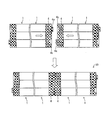
- FIG. 5 is a plan view showing a continuous illumination device 10a in which four illumination devices 1 of FIG. As shown in FIG. 5, in the continuous illumination device 10, the linearity with the illumination devices 1 and 1 is secured by fitting the convex portions 4 a and the recesses 4 b of the adjacent illumination devices 1 and 1. A plurality of units 1 can be easily connected.
- convex portions 4 a and concave portions 4 b are formed at both ends of the side cover 4. That is, in FIG. 4, the continuous illumination device 10 has a configuration in which a plurality of illumination devices 1 of FIG. For this reason, the convex part 4a and the recessed part 4b are each arrange
- the convex part 4a and the recessed part 4b are mutually fitted, and the illuminating device 1 is provided continuously in the longitudinal direction.
- the convex part 4a and the recessed part 4b are each formed in each illuminating device 1, position alignment of the adjacent illuminating device 1 will also become easy.
- the linearity of the some illuminating device 1 in a connection state is ensured, and the some illuminating device 1 can be connected easily.
- the convex part 4a and the recessed part 4b are formed in the both ends of all the side covers 4. As shown in FIG. For this reason, in the continuous illumination device 10, the convex portions 4a and the concave portions 4b formed on the side covers 4 that are not continuously provided at both ends are visually recognized. However, the convex portion 4a and the concave portion 4b may be formed only on the side cover 4 on the side where they are provided. That is, the convex part 4a and the recessed part 4b do not need to be formed in the side cover 4 which is not fitted among the illumination devices 1 at both ends.
- the continuous illumination device 10 may have a configuration in which a plurality of illumination devices 1 each having the convex portion 4a and the concave portion 4b are provided continuously only on the side cover 4 on the side where the continuous illumination device 10 is provided.
- the plurality of units 1 can be easily connected while securing the linearity with the lighting devices 1 and 1 by fitting the convex portions 4a and the concave portions 4b of the adjacent lighting devices 1 and 1 together. Can do.
- the fitting portions are not formed in the side covers 4 at both ends, when the continuous illumination device 10 is configured, the convex portions 4a are not visually recognized by the concave portions 4b. can do.
- FIG. 1 is a perspective view showing an end portion of a lighting device 1 according to an embodiment of the present invention.
- the continuous illumination is caused by thermal expansion that occurs when the LED module 22 is turned on, vibrations due to the passage of a large mass of a rail vehicle / truck, an earthquake, or the like.
- Abnormal noise occurs in the devices 10 and 10a.
- the lighting device 1 expands due to heat and when vibration is applied to the lighting device 1, a force is applied in the longitudinal direction between the adjacent lighting devices 1.
- a frictional force acts on the contact portion between the adjacent lighting devices 1. That is, the continuous surface (end surface of the side cover 4) of each lighting device 1 is rubbed. For this reason, abnormal noise occurs in the continuous illumination devices 10 and 10a.
- a buffer portion 5 is provided on the inner surface of the recess 4 b formed in the side cover 4 to reduce the force generated between the adjacent lighting devices 1.
- the buffer part 5 reduces the force (frictional force) applied to the contact part with the side cover 4 of the adjacent lighting device 1, and reduces the generation of sound caused by the force.
- the buffer portion 5 is not particularly limited as long as it can reduce the force applied between the adjacent device main bodies 2 and 2 in the fitted state of the lighting devices 1 and 1 and can reduce the generation of abnormal noise.
- the buffer portion 5 is preferably made of a material having at least one of sound absorption and frictional force absorption (impact absorption).
- the buffer part 5 can be comprised from a fiber material, an elastic member, etc.
- the fiber material include felt and nonwoven fabric.
- the elastic member include rubber.
- the buffer 5 may be a gel-like member formed on the inner surface of the recess 4b (for example, a member laid on the bottom of the leg as a fall prevention member for a liquid crystal television), or the protrusion 4a and the recess 4b. Teflon (registered trademark) processing may be applied to the contact portion.
- the buffer part 5 When the buffer part 5 is made of a fiber material, the friction coefficient due to contact between the end faces of the adjacent lighting devices 1 (end faces of the side covers 4) is reduced. This makes it difficult for abnormal noise to occur and allows the fiber material to absorb abnormal noise.
- the buffer part 5 when the buffer part 5 is comprised from an elastic member, the frictional force concerning the end surface (end surface of the side cover 4) of the adjacent illuminating device 1 is reduced. That is, the elastic member absorbs the frictional force, so that the force with which the end surface of the lighting device 1 (the end surface of the side cover 4) is rubbed can be reduced.
- the same effect can be obtained when the buffer portion 5 is subjected to a gel-like member or Teflon processing as described above. Therefore, in any case, it is possible to prevent the generation of abnormal noise generated in the plurality of connected lighting devices 1.
- the illuminating device 1 As an engaging part fitted to the edge part of the apparatus main body 2 of the adjacent illuminating device 1.1 in the edge part (end part of the illuminating device 1) of the apparatus main body 2, Convex part 4a and concave part 4b are provided. Furthermore, the buffer part 5 is formed in the recessed part 4b. That is, the recessed part 4b is provided with the buffer part 5 in at least a part of the contact part with the side cover 4 of the adjacent lighting device 1. Thereby, the adjacent illuminating devices 1.1 can be accurately aligned. Therefore, it is possible to easily connect the plurality of lighting devices 1 and 1 while ensuring the linearity of the plurality of lighting devices 1 and 1.
- the recess 4b includes the buffer portion 5, the force applied between the adjacent device main bodies 2 and 2 in the fitted state of the adjacent lighting devices 1 and 1 is reduced. That is, the frictional force applied to the contact portions of the lighting devices 1 that are adjacent to each other (side covers 4 that are adjacent to each other) is reduced. Thereby, generation
- the buffer part 5 is formed in the recessed part 4b.
- the buffer part 5 should just be formed in at least one part of the contact part with the side cover 4 of the adjacent illuminating device 1.
- the buffer part 5 should just be formed in at least one part of the inner surface (inner surface) of the recessed part 4b, It is more preferable to form in the bottom face of the recessed part 4b, and forming in all the surfaces of the inner surface of the recessed part 4b. preferable.
- the effect of preventing the generation of abnormal noise can be enhanced.
- the buffer part 5 when the buffer part 5 is formed in the recessed part 4b, it can be made not conspicuous compared with the case where it forms in the convex part 4a, and the beauty
- a pair of convex portions 4 a and concave portions 4 b are provided on the end surfaces 41 of the side covers 4 at both ends of the device main body 2.
- the convex portion 4 a may be formed on the side cover 4 at one end
- the concave portion 4 b may be formed on the other side cover 4.
- the linearity of the continuous illumination devices 10 and 10a can be ensured.
- the same side cover 4 can be applied to both ends of the lighting device 1 (both ends of the device main body 2). For this reason, it is not necessary to manufacture the side cover 4 dedicated to one end and the side cover 4 dedicated to the other end. Therefore, the manufacturing cost of the side cover 4 and consequently the manufacturing cost of the lighting device 1 can be reduced.
- the length of the convex part 4a formed in the side cover 4 of the illuminating device 1, and the depth of the concave part 4b formed in the side cover 4 of the adjacent illuminating device 1 are substantially the same.
- the end surface (continuous surface) of the side cover 4 of the illumination device 1 is in contact with the end surface (continuous surface) of the side cover 4 of the adjacent illumination device 1.
- FIG. 6 is a plan view showing a lighting device in which a plurality of lighting devices 1 according to the embodiment of the present invention are connected in series.
- the illumination device 1 of FIG. 6 differs from the configuration of FIG. 4 only in that the length of the convex portion 4a is set to be greater than or equal to the depth of the concave portion 4b.
- the convex portion 4 a and the concave portion 4 b are configured such that a part between the end portions of the adjacent apparatus main bodies 2 is separated in the fitted state.
- the end surfaces 41 and 41 of the illuminating devices 1 and 1 adjacent to each other are provided apart from each other. That is, the end surfaces 41 and 41 (device main bodies 2 and 2) of the side covers 4 and 4 in the lighting devices 1 and 1 adjacent to each other do not contact each other. For this reason, even if thermal expansion or vibration of the lighting device 1 occurs, the force applied between the adjacent end faces 41 can be more reliably reduced. Therefore, it is possible to more effectively prevent the generation of abnormal noise.
- the alignment of the illuminating device 1 can be accurately performed by fitting the convex portions 4a and the concave portions 4b, it is easy to attach a plurality of illuminating devices 1 linearly. Further, even if heat or vibration is applied to the lighting device 1, the force generated between the end faces 41 and 41 can be reduced, so that the linearity of a plurality of lighting devices 1 provided in the continuous lighting device 10b can be maintained. it can.
- FIG. 7 is a perspective view showing an end portion of a lighting device 1b according to another embodiment of the present invention.
- the recess 4 b ′ is formed so as to penetrate in the thickness direction of the side cover 4.
- the illumination devices 1 other than both ends of the continuous illumination device 10 are removed due to a failure or the like in a state where the convex portion 4 a and the concave portion 4 b are engaged with each other (downward). May need to be pulled down).
- the concave portion 4 b is not penetrating in the thickness direction of the side cover 4, it is necessary to remove the lighting devices 1 in order from the end lighting device 1 among the plurality of connected lighting devices 1. It must be removed until there is no lighting device 1.
- the illuminating device 1 provided with LED (LED module 22) as a light source was demonstrated.
- the light source is not limited to the LED, and may be various light emitting elements such as a phosphor, an electroluminescence element, and a semiconductor light source. Moreover, what is necessary is just to set the color of a light source arbitrarily.
- LEDs Light Emitting Diodes
- advantages such as long life and low power consumption.
- the continuous illumination device 10 in which a plurality of illumination devices 1 are continuously provided in the longitudinal direction has been described.
- the side cover 4 may be attached in the short direction of the lighting device 1. That is, the connecting direction of the lighting device 1 in the continuous lighting device 10 is not limited to the longitudinal direction.
- the fitting portion is separated between the end portions of the adjacent device main bodies in the fitted state.
- a gap is partially formed between the end surfaces of the device main bodies in the adjacent lighting devices. That is, the apparatus main bodies of adjacent lighting apparatuses do not contact each other. For this reason, even if thermal expansion, vibration, or the like of the lighting device occurs, the force applied between the end surfaces of the adjacent device main bodies can be more reliably reduced. Accordingly, it is possible to more effectively prevent the generation of abnormal noise and to maintain the linearity of the lighting device in a continuous state.
- the fitting portion includes a convex portion and a concave portion into which the convex portion is fitted, and the concave portion may be formed so as to penetrate in the attachment direction to the attachment surface.
- the recessed part which comprises a fitting part has penetrated in the attachment surface direction of the illuminating device. Therefore, even after the lighting devices are continuously provided, the lighting device can be easily detached. Therefore, it is possible to easily repair or replace some of the lighting devices among a plurality of lighting devices.
- the fitting portion includes a convex portion and a concave portion into which the convex portion is fitted, and a pair of the convex portion and the concave portion is provided at an end portion of the apparatus body. Is preferred.
- a pair of a convex portion and a concave portion is formed at the end of the apparatus main body.
- the same member can be applied to both ends of the lighting device (both ends of the apparatus main body).
- the pair of a convex part and a recessed part may be one pair, or multiple pairs.
Landscapes
- Engineering & Computer Science (AREA)
- General Engineering & Computer Science (AREA)
- Non-Portable Lighting Devices Or Systems Thereof (AREA)
Abstract
本発明の照明装置(1)は、隣り合う照明装置(1)に連設するため、サイドカバー(4)に嵌合部として凸部(4a)および凹部(4b)が設けられている。凹部(4b)の内面には、嵌合状態において隣接する照明装置(1)・(1)間に生じる力を低減する緩衝部(5)が設けられている。
Description
本発明は、複数連設することが可能な照明装置に関する。
照明装置の用途は多岐に渡っており、家庭用照明のように比較的狭い室内を照明する場合もあれば、オフィスや展示場などのように広い室内を照明する場合もある。図8は、従来のストレート型の照明装置100を示す斜視図である。広い室内を照明する場合、図8のような照明装置100が、複数台、直線状に連設される。
例えば、特許文献1には、複数の照明装置の連設方法が開示されている。図9は、特許文献1に記載された互いに隣接する照明装置200a・200bの連設構造を示す斜視図である。図9に示すように、照明装置200aのフレーム201aにおける長手方向の端部に凸部202が形成されており、照明装置200bのフレーム201bにおける長手方向の端部に凹部203が形成されている。凸部202と凹部203とは互いに係合する。このため、フレーム201aとフレーム201bとを連結すると、凸部202と凹部203とが係合する。従って、フレーム201aとフレーム201bとが、隙間を生じることなく連設される。これにより、複数の照明装置200a・200b・・・が、直線的に連設される。
しかしながら、特許文献1に記載された照明装置の連設構造では、異音が発生すると共に、照明装置の直線性が損なわれるという問題がある。
具体的には、図9に示すように、照明装置200aでは、フレーム201aの端部の全面に凸部202が形成され、照明装置200bでは、フレーム201bの端部の全面に凹部203が形成されている。そして、上述のように、フレーム201aとフレーム201bとが、隙間を生じることなく連設される。その結果、点灯時に生じる熱に伴うフレーム201aとフレーム201bの膨張、または、質量の大きい鉄道車両またはトラック類の近傍通過や地震等による振動によって、照明装置200a・200bの間に力が加わることで異音が発生することが明らかになった。
また、図10は、図8の照明装置100を4つ連設した状態を示す平面図である。より詳細には、図10は、上記異音を防止するために、図8の照明装置100間に隙間を設けて連設した状態を示す図である。作業者が照明装置100を天井に直接取り付ける連設施工では、隣り合う照明装置100同士の位置関係を把握しながら取付作業を行うことが困難である。また、上記隙間によって連設していくごとに照明装置100の取り付け位置に誤差が生じる。その結果、図10のように連設された照明装置100の直線性が損なわれる虞がある。
そこで、本発明は、上記従来の問題点に鑑みてなされてものであり、その目的は、複数の連設された照明装置に生じる異音の発生を低減するとともに連設された複数の照明装置の直線性を維持することのできる照明装置を提供することにある。
本発明の照明装置は、上記の課題を解決するために、取付面に設置される装置本体と、
装置本体に搭載された光源とを備える照明装置であって、
上記装置本体の端部に、隣接する照明装置の装置本体の端部と嵌合する嵌合部を備え、
上記嵌合部は、嵌合状態において隣接する装置本体間に加わる力を低減する緩衝部を備えることを特徴としている。
装置本体に搭載された光源とを備える照明装置であって、
上記装置本体の端部に、隣接する照明装置の装置本体の端部と嵌合する嵌合部を備え、
上記嵌合部は、嵌合状態において隣接する装置本体間に加わる力を低減する緩衝部を備えることを特徴としている。
上記の構成によれば、装置本体の端部に、隣接する照明装置の装置本体の端部と嵌合する嵌合部を備えている。これにより、隣接する照明装置を正確に位置合わせすることができる。従って、複数の照明装置の直線性を確保しつつ、複数の照明装置を簡便に連設することができる。
さらに、上記の構成によれば、嵌合部が緩衝部を備えているため、隣接する照明装置の嵌合状態において、隣接する装置本体間に加わる力が低減される。これにより、複数の連設された照明装置に生じる異音の発生を低減することができる。さらに、熱または振動が照明装置に加わっても、連設状態における照明装置の直線性を維持することができる。
本発明の他の目的、特徴、および優れた点は、以下に示す記載によって十分分かるであろう。また、本発明の利点は、添付図面を参照した次の説明で明白になるであろう。
以上のように、本発明によれば、複数の連設された照明装置に生じる異音の発生を低減するとともに連設された複数の照明装置の直線性を維持することのできる照明装置を提供することができるという効果を奏する。
以下、本発明の一実施形態について図面に基づいて説明する。本実施形態では、本発明に係る照明装置の一例として、天井等の取付面に直付されるストレート型の照明装置(灯具)について説明する。以下の説明では、便宜上、室内(床)側を「下方(下側)」、天井(取付面)側を「上方(上側)」として説明する。
図2は、本発明の実施の一形態に係る照明装置1を示す斜視図である。図3は、図2の照明装置1に設けられた装置本体2の平面図であり、より詳細には、床側から見た装置本体2の平面図である。
図2に示すように、照明装置1は、天井等の取付面に設置される装置本体2と、装置本体2に取り付けられた照明カバー3と、装置本体2および照明カバー3の両端部に装着されたサイドカバー4とを備えている。
装置本体2は、図3に示すように、シャーシ21と、LEDモジュール(光源)22と、電源回路基板23とを備えている。
照明装置1はストレート型であるため、シャーシ21は、平面視長方形となっている。シャーシ21は、例えば、アルミニウム、鉄、樹脂などの放熱性の高い材料から構成することができる。これにより、シャーシ21に搭載されたLEDモジュール22および電源回路基板23に生じる熱を、シャーシ21によって効率的に放熱することができる。さらに、シャーシ21をアルミニウムや鉄などの光を反射する材料から構成すれば、シャーシ21が、LEDモジュール22からの出射光を反射させる反射部としても機能する。
LEDモジュール22は、照明装置1における光源である。LEDモジュール22は、LED基板と、LED基板に搭載された複数のLEDから構成されている。照明装置1では、2本の長尺(棒状)のLEDモジュール22が、シャーシ21の長手方向(長辺)に沿って設けられている。2本のLEDモジュール22は、離間して配置されている。
電源回路基板23は、LEDモジュール22へ電力を供給する電源回路等の各種電子部品が実装されたものである。電源回路基板23は、LEDモジュール22とLEDモジュール22との間、つまり、シャーシ21の中央部に設けられている。電源回路基板23の中央部には、電源回路基板23に電源ケーブルを接続するために、貫通穴24が形成されている。一方、電源回路基板23の両端部には、装置本体2を取付面にネジ止め固定するために、固定用穴25が形成されている。なお、電源回路基板23には、LEDモジュール22の調光用の端子台が設けられていてもよい。これにより、照明装置1の調光が可能となる。
照明カバー3は、LEDモジュール22からの出射光を透過する。照明カバー3は、拡散カバー3aとセンターカバー3bとから構成されている。拡散カバー3aは、各LEDモジュール22の光出射方向側に設けられている。拡散カバー3aは、LEDモジュール22からの出射光を透光および拡散させる。拡散カバー3aは、耐熱性材料から形成することが好ましい。例えば、乳白色(半透明)のポリカーボネート樹脂またはアクリルは、耐衝撃性、耐熱性、光拡散性に優れているため、拡散カバー3aの構成材料として好適である。一方、センターカバー3bは、電源回路基板23を隠すように設けられている。センターカバー3bは、サイドカバー4に設けられた案内ガイド(図示せず)に着脱可能に固定されている。
サイドカバー4は、照明装置1の長手方向の両端部(装置本体2の長手方向の両端部)に設けられている。サイドカバー4の外側面(照明装置1の側面または端面)の一部には、凸部4aおよび凹部4bが形成されている。凸部4aおよび凹部4bは、照明装置1を複数連設するための嵌合部である。照明装置1の連設については後述する。サイドカバー4は、装置本体2および照明カバー3の両端部に装着されている。サイドカバー4は、例えば、ポリカーボネート樹脂から構成することができる。
このように、照明装置1は、LEDモジュール22からの出射光を、照明カバー3(拡散カバー3a)によって拡散させ、均一な光を室内側へ照射する。また、照明装置1は、複数連設できるようになっている。図4は、本発明実施一の形態に係る照明装置1を複数連設した、連設型照明装置10を示す平面図である。
図5は、図2の照明装置1を4つ連設した、連設型照明装置10aを示す平面図である。図5のように、連設型照明装置10においても、隣り合う照明装置1・1の凸部4aと凹部4bとを嵌合させることにより、照明装置1・1との直線性を確保しつつ、複数のユニット1を簡単に連設することができる。
なお、図4では、全ての照明装置1は、サイドカバー4の両端部に凸部4aおよび凹部4bがそれぞれ形成されている。すなわち、図4において、連設型照明装置10は、図2の照明装置1を複数連設した構成となっている。このため、互いに対向するサイドカバー4の端面に、それぞれ、凸部4aおよび凹部4bが配置される。つまり、ある照明装置1の凸部4aは、隣接する照明装置1の凹部4bに対応しており、ある照明装置1の凹部4bは、隣接する照明装置1の凸部4aに対応する。これにより、照明装置1の連設時には、凸部4aおよび凹部4bが互いに嵌合し、照明装置1が長手方向に連設される。このように、各照明装置1に、それぞれ凸部4aおよび凹部4bが形成されていれば、隣接する照明装置1の位置合わせも容易になる。また、連設状態における複数の照明装置1の直線性を確保して、複数の照明装置1を簡便に連設することができる。
なお、図4では、全てのサイドカバー4の両端部に凸部4aおよび凹部4bが形成されている。このため、連設型照明装置10では、両端の連設されないサイドカバー4に形成された凸部4aおよび凹部4bが視認される。しかし、凸部4aおよび凹部4bは、連設される側のサイドカバー4にのみ、形成されていてもよい。つまり、両端の照明装置1のうち、嵌合しない方のサイドカバー4には、凸部4aおよび凹部4bが形成されていなくてもよい。すなわち、連設型照明装置10は、連設される側のサイドカバー4にのみ、凸部4aおよび凹部4bがそれぞれ形成された照明装置1を複数連設した構成であってもよい。この場合も隣り合う照明装置1・1の凸部4aと凹部4bとを嵌合させることにより、照明装置1・1との直線性を確保しつつ、複数のユニット1を簡単に連設することができる。さらに、両端のサイドカバー4には、嵌合部(凸部4a,凹部4b)が形成されないため、連設型照明装置10を構成したとき、外観上、凸部4aも凹部4bが視認されなくすることができる。
ここで、図1に基づいて、照明装置1の特徴的構成について説明する。図1は、本発明の実施の一形態に係る照明装置1の端部を示す斜視図である。
図4,図5のように、照明装置1を複数連設すると、LEDモジュール22の点灯時に生じる熱膨張、質量の大きい鉄道車両/トラック類の近傍通過や地震等による振動によって、連設型照明装置10,10aに異音が発生する。具体的には、熱により照明装置1が膨張するとき、および、照明装置1に振動が加わるときには、隣接する照明装置1・1間において長手方向に力が加わる。その結果、隣り合う照明装置1・1の接触部に摩擦力が働く。つまり、各照明装置1の連設面(サイドカバー4の端面)が擦れ合う。このため、連設型照明装置10,10aに異音が発生する。
そこで、照明装置1では、このような異音対策が施されている。具体的には、図1のように、サイドカバー4に形成された凹部4bの内面に、隣接する照明装置1・1間に生じる力を低減する緩衝部5が設けられている。
緩衝部5は、隣り合う照明装置1のサイドカバー4との接触部に加わる力(摩擦力)を低減し、その力によって生じる音の発生を低減する。緩衝部5は、照明装置1・1の嵌合状態において隣接する装置本体2・2間に加わる力を低減し、異音の発生を低減できるものであれば特に限定されるものではない。例えば、緩衝部5は、吸音性および摩擦力吸収性(衝撃吸収性)の少なくとも一方を有する材料から構成されていることが好ましい。
例えば、緩衝部5は、繊維材、弾性部材などから構成することができる。繊維材としては、例えば、フェルト、不織布等が挙げられる。弾性部材としては、ゴムなどが挙げられる。また、緩衝部5は、凹部4bの内面に形成されたジェル状の部材(例えば、液晶テレビの転倒防止部材として脚部底面に敷くもの等)であってもよいし、凸部4aと凹部4bとの接触部にテフロン(登録商標)加工を施したものであってもよい。
緩衝部5を、繊維材から構成した場合、隣り合う照明装置1の端面(サイドカバー4の端面)同士の接触による摩擦係数が低減される。これにより、異音が発生しにくくなると共に、繊維材に異音を吸収させることもできる。一方、緩衝部5を、弾性部材から構成した場合、隣り合う照明装置1の端面(サイドカバー4の端面)にかかる摩擦力が低減される。つまり、弾性部材が、摩擦力を吸収することにより、照明装置1の端面(サイドカバー4の端面)が擦れる力を低減することができる。緩衝部5が上述のようなジェル状の部材またはテフロン加工を施した場合も、同様の効果が得られる。従って、いずれの場合であっても、複数の連設された照明装置1・1に生じる異音の発生を防止することができる。
このように、照明装置1によれば、装置本体2の端部(照明装置1の端部)に、隣接する照明装置1・1の装置本体2の端部と嵌合する嵌合部として、凸部4aおよび凹部4bを備えている。さらに、凹部4bには、緩衝部5が形成されている。すなわち、凹部4bは、隣り合う照明装置1のサイドカバー4との接触部の少なくとも一部に、緩衝部5を備えている。これにより、隣接する照明装置1・1を正確に位置合わせすることができる。従って、複数の照明装置1・1の直線性を確保しつつ、複数の照明装置1・1を簡便に連設することができる。
さらに、凹部4bが緩衝部5を備えているため、隣接する照明装置1・1の嵌合状態において、隣接する装置本体2・2間に加わる力が低減される。つまり、互いに隣り合う照明装置1(互いに隣り合うサイドカバー4)の接触部に加わる摩擦力が低減される。これにより、照明装置1,1が複数連設された連設型照明装置10,10aに生じる異音の発生を低減することができる。さらに、熱または振動が照明装置1に加わっても、連設状態における照明装置1(連設型照明装置10,10a)の直線性を維持することができる。
なお、図1では、緩衝部5は、凹部4bに形成されている。しかし、緩衝部5は、隣り合う照明装置1のサイドカバー4との接触部の少なくとも一部に、形成されていればよい。つまり、緩衝部5は、凹部4bに形成することに限定されるものではなく、凸部4aに形成してもよいし、サイドカバー4の端面41に形成してもよい。また、緩衝部5は、凹部4bの内面(内側面)の少なくとも一部に形成すればよく、凹部4bの底面に形成することがより好ましく、凹部4bの内面の全ての面に形成することが好ましい。緩衝部5の形成領域が広くなるほど、異音の発生防止効果を高めることができる。また、緩衝部5が凹部4b内に形成されている場合、凸部4aに形成した場合よりも目立たなくすることができ、美観が損なわれない。
また、照明装置1では、装置本体2の両端部のサイドカバー4の端面41に、それぞれ、凸部4aおよび凹部4bが1対設けられている。しかし、一方の端部のサイドカバー4に凸部4aを、他方のサイドカバー4に凹部4bを形成してもよい。この場合も、連設型照明装置10,10aの直線性を確保することができる。ただし、両端部のサイドカバー4の端面41に、それぞれ、凸部4aおよび凹部4bが1対以上設けられていることが好ましい。これにより、照明装置1の両端部(装置本体2の両端部)に、同一のサイドカバー4を適用することができる。このため、一方の端部専用のサイドカバー4と、他方の端部専用のサイドカバー4とを製造する必要がない。従って、サイドカバー4の製造コスト、ひいては照明装置1の製造コストを削減することができる。
また、本実施形態では、図4に示すように、照明装置1のサイドカバー4に形成された凸部4aの長さと、隣接する照明装置1のサイドカバー4に形成された凹部4bの深さとが略同一となっている。このため、連設型照明装置10では、照明装置1のサイドカバー4の端面(連設面)と、隣接する照明装置1のサイドカバー4の端面(連設面)とが当接している。
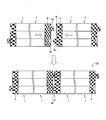
しかし、隣り合う照明装置1に連設されたときに、互いに対向するサイドカバー4の端面(連設面)が離間するようになっていることが好ましい。図6は、本発明実施一の形態に係る照明装置1を複数連設した照明装置を示す平面図である。図6の照明装置1は、凸部4a長さが、凹部4bの深さ以上に設定されている点のみが、図4の構成とは異なる。図6の構成では、凸部4aおよび凹部4bは、嵌合状態において隣接する装置本体2の端部間の一部が離間するようになっている。すなわち、照明装置1を連設して連設型照明装置10bを構成すると、互いに隣り合う照明装置1・1の端面41,41が、離間して設けられる。つまり、互いに隣り合う照明装置1・1におけるサイドカバー4,4の端面41・41同士(装置本体2・2同士)が接触しない。このため、たとえ照明装置1の熱膨張や振動等が生じたとしても、隣接する端面41,41間に加わる力をより確実に低減することができる。従って、異音の発生をより効果的に防止することができる。また凸部4aおよび凹部4bの嵌合により照明装置1の位置合わせが正確にできるので、複数の照明装置1を直線的に取り付けることも容易である。また、熱または振動が照明装置1に加わっても、端面41,41間に生じる力を低減できるので、連設型照明装置10bにおける複数連設された照明装置1の直線性を維持することができる。
一方、図1の照明装置1では、凹部4bは、サイドカバー4の厚さ方向の中央部に形成されており、凹部4bは、サイドカバー4の厚さ方向に貫通していない。しかし、凹部4bは、サイドカバー4の厚さ方向(取付面への取付方向)に貫通して形成されていてもよい。図7は、本発明の別の実施の一形態に係る照明装置1bの端部を示す斜視図である。図7の照明装置1bでは、凹部4b’は、サイドカバー4の厚さ方向に貫通するように形成されている。これにより、照明装置1bの連設後であっても、照明装置1bを下方向へ取り外すことが可能となる。従って、複数連設された照明装置1bのうち(連設型照明装置10のうち)、一部の照明装置1bを容易に修理または交換することができる。
具体的には、連設型照明装置10では、凸部4aと凹部4bとが互いに係合した状態で、故障等によって連設型照明装置10の両端以外の照明装置1を取り外す(下方向へ引き降ろす)必要が生じる場合がある。この場合、図1のように、凹部4bが、サイドカバー4の厚さ方向に非貫通であると、複数の連接された照明装置1のうち端部の照明装置1から順番に、取り外す必要のない照明装置1まで取り外してゆかねばならない。
これに対し、図7のように、凹部4b’が、サイドカバー4の厚さ方向に貫通している場合、上下方向の拘束がない。従って、取り外す必要のある照明装置1のみを下方向へ取り外すことが可能となる。
なお、本実施形態では、光源としてLED(LEDモジュール22)を備える照明装置1について説明した。しかし、光源はLEDに限定されるものではなく、蛍光体、エレクトロルミネッセンス素子、半導体光源等の各種発光素子であってもよい。また、光源の色は任意に設定すればよい。ただし、LED(Light Emitting Diode:発光ダイオード)は、長寿命、低消費電力といった利点を有する。
また、本実施形態では、複数の照明装置1を長手方向に連設した、連設型照明装置10について説明した。しかし、複数の照明装置1を短手方向に連設することもできる。この場合、サイドカバー4を照明装置1の短手方向に装着すればよい。つまり、連設型照明装置10における照明装置1の連設方向は、長手方向に限定されるものではない。
本発明の照明装置において、上記嵌合部は、嵌合状態において隣接する装置本体の端部間の少なくとも一部が離間するようになっていることが好ましい。
上記の構成によれば、照明装置を複数連設すると、隣接する照明装置における装置本体の端面間に、部分的に隙間が形成される。つまり、隣接する照明装置の装置本体同士が接触しない。このため、たとえ照明装置の熱膨張や振動等が生じたとしても、隣接する装置本体の端面間に加わる力をより確実に低減することができる。従って、異音の発生をより効果的に防止することができると共に、連設状態における照明装置の直線性を維持することができる。
本発明の照明装置において、上記嵌合部は、凸部とその凸部が嵌合する凹部とからなり、上記凹部は、上記取付面への取付方向に貫通するように形成されていてもよい。
上記の構成によれば、嵌合部を構成する凹部が、照明装置の取付面方向に貫通している。これにより、照明装置の連設後であっても、照明装置を容易に取り外すことができる。従って、複数連設された照明装置のうち、一部の照明装置を容易に修理または交換することができる。
本発明の照明装置において、上記嵌合部は、凸部とその凸部が嵌合する凹部とからなり、上記装置本体の端部に、上記凸部と凹部との対が設けられていることが好ましい。
上記の構成によれば、装置本体の端部に、凸部と凹部との対が形成されている。これにより、照明装置の両端部(装置本体の両端部)に、同一の部材を適用することができる。このため、装置本体における一方の端部専用の部材と、他方の端部専用の部材とを製造する必要がない。従って、装置本体の製造コスト、ひいては照明装置の製造コストを削減することができる。なお、凸部と凹部との対は、1対であっても、複数対であってもよい。
本発明は上述した実施形態に限定されるものではなく、請求項に示した範囲で種々の変更が可能である。すなわち、請求項に示した範囲で適宜変更した技術的手段を組み合わせて得られる実施形態についても本発明の技術的範囲に含まれる。すなわち、発明の詳細な説明の項においてなした具体的な実施態様または実施例は、あくまでも、本発明の技術内容を明らかにするものであって、そのような具体例にのみ限定して狭義に解釈されるべきものではなく、本発明の精神と次に記載する特許請求事項の範囲内で、いろいろと変更して実施することができるものである。
1 照明装置
2 装置本体
3 照明カバー
4a 凸部(嵌合部)
4b 凹部(嵌合部)
4b’ 凹部(嵌合部)
5 緩衝部
22 LEDモジュール(光源)
2 装置本体
3 照明カバー
4a 凸部(嵌合部)
4b 凹部(嵌合部)
4b’ 凹部(嵌合部)
5 緩衝部
22 LEDモジュール(光源)
Claims (6)
- 取付面に設置される装置本体と、
装置本体に搭載された光源とを備える照明装置であって、
上記装置本体の端部に、隣接する照明装置の装置本体の端部と嵌合する嵌合部を備え、
上記嵌合部は、嵌合状態において隣接する装置本体間に加わる力を低減する緩衝部を備えることを特徴とする照明装置。 - 上記嵌合部は、嵌合状態において隣接する装置本体の端部間の少なくとも一部が離間するようになっていることを特徴とする請求項1に記載の照明装置。
- 上記嵌合部は、凸部とその凸部が嵌合する凹部とからなり、
上記凹部は、上記取付面への取付方向に貫通するように形成されていることを特徴とする請求項1または2に記載の照明装置。 - 上記嵌合部は、凸部とその凸部が嵌合するする凹部とからなり、
上記装置本体の端部に、上記凸部と凹部との対が設けられていることを特徴とする請求項1~3のいずれか1項に記載の照明装置。 - 上記凸部の長さが、上記凹部の深さ以上であることを特徴とする請求項3または4に記載の照明装置。
- 上記緩衝部は、繊維材、または、弾性部材から構成されていることを特徴とする請求項1~5のいずれか1項に記載の照明装置。
Applications Claiming Priority (2)
| Application Number | Priority Date | Filing Date | Title |
|---|---|---|---|
| JP2011173437A JP2013037915A (ja) | 2011-08-08 | 2011-08-08 | 照明装置 |
| JP2011-173437 | 2011-08-08 |
Publications (1)
| Publication Number | Publication Date |
|---|---|
| WO2013021793A1 true WO2013021793A1 (ja) | 2013-02-14 |
Family
ID=47668310
Family Applications (1)
| Application Number | Title | Priority Date | Filing Date |
|---|---|---|---|
| PCT/JP2012/068247 Ceased WO2013021793A1 (ja) | 2011-08-08 | 2012-07-18 | 照明装置 |
Country Status (2)
| Country | Link |
|---|---|
| JP (1) | JP2013037915A (ja) |
| WO (1) | WO2013021793A1 (ja) |
Families Citing this family (4)
| Publication number | Priority date | Publication date | Assignee | Title |
|---|---|---|---|---|
| JP6238173B2 (ja) * | 2014-04-11 | 2017-11-29 | パナソニックIpマネジメント株式会社 | Led照明器具 |
| JP6566199B2 (ja) * | 2015-06-30 | 2019-08-28 | 東芝ライテック株式会社 | 照明装置 |
| JP6417494B2 (ja) * | 2016-03-07 | 2018-11-07 | 興和株式会社 | 照明装置 |
| WO2019073768A1 (ja) * | 2017-10-10 | 2019-04-18 | パナソニックIpマネジメント株式会社 | 連結ユニットおよび連結器具 |
Citations (3)
| Publication number | Priority date | Publication date | Assignee | Title |
|---|---|---|---|---|
| JPS4829684U (ja) * | 1971-08-13 | 1973-04-11 | ||
| JPS5581211U (ja) * | 1978-11-30 | 1980-06-04 | ||
| JPS6288303U (ja) * | 1985-11-25 | 1987-06-05 |
-
2011
- 2011-08-08 JP JP2011173437A patent/JP2013037915A/ja active Pending
-
2012
- 2012-07-18 WO PCT/JP2012/068247 patent/WO2013021793A1/ja not_active Ceased
Patent Citations (3)
| Publication number | Priority date | Publication date | Assignee | Title |
|---|---|---|---|---|
| JPS4829684U (ja) * | 1971-08-13 | 1973-04-11 | ||
| JPS5581211U (ja) * | 1978-11-30 | 1980-06-04 | ||
| JPS6288303U (ja) * | 1985-11-25 | 1987-06-05 |
Also Published As
| Publication number | Publication date |
|---|---|
| JP2013037915A (ja) | 2013-02-21 |
Similar Documents
| Publication | Publication Date | Title |
|---|---|---|
| KR200462138Y1 (ko) | 레이스웨이 일체형 주차장용 조명기구 | |
| CN203442630U (zh) | 照明器具 | |
| WO2013021793A1 (ja) | 照明装置 | |
| JP6096607B2 (ja) | 照明装置 | |
| JP6223005B2 (ja) | 照明器具 | |
| JP6145917B2 (ja) | 光源装置及びそれを用いた照明器具 | |
| JP2016081776A (ja) | 照明装置及び照明装置用発光ユニット | |
| JP2016015304A (ja) | 照明装置 | |
| KR200449793Y1 (ko) | 엘이디 조명기구 | |
| KR102199621B1 (ko) | 직부형 led 엣지평판 천장등장치 | |
| JP5814447B1 (ja) | 照明装置及び照明装置用発光ユニット | |
| KR20150042130A (ko) | 조명 기구 | |
| JP2024114894A (ja) | 照明器具 | |
| KR101781427B1 (ko) | Led 조명 장치의 체결 구조 | |
| JP5814449B1 (ja) | 照明装置及び照明装置用発光ユニット | |
| KR102171917B1 (ko) | Led 엣지평판형 천장등 | |
| KR101404302B1 (ko) | 엘이디 조명 장치 및 이의 제조방법 | |
| KR101179172B1 (ko) | 형광등형 엘이디 조명등 장치 | |
| JP5893693B1 (ja) | 照明装置用発光ユニット及び照明装置 | |
| JP2015181125A (ja) | 照明装置 | |
| JP5814448B1 (ja) | 照明装置及び照明装置用発光ユニット | |
| WO2012157145A1 (ja) | 照明装置 | |
| KR102151007B1 (ko) | Led 엣지평판 천장등장치 | |
| KR20080113620A (ko) | 투사 광학계의 광원부 구조 | |
| JP2019133810A (ja) | 光源ユニット及び照明器具 |
Legal Events
| Date | Code | Title | Description |
|---|---|---|---|
| 121 | Ep: the epo has been informed by wipo that ep was designated in this application |
Ref document number: 12821938 Country of ref document: EP Kind code of ref document: A1 |
|
| NENP | Non-entry into the national phase |
Ref country code: DE |
|
| 122 | Ep: pct application non-entry in european phase |
Ref document number: 12821938 Country of ref document: EP Kind code of ref document: A1 |