WO2013021561A1 - Earth terminal - Google Patents
Earth terminal Download PDFInfo
- Publication number
- WO2013021561A1 WO2013021561A1 PCT/JP2012/004716 JP2012004716W WO2013021561A1 WO 2013021561 A1 WO2013021561 A1 WO 2013021561A1 JP 2012004716 W JP2012004716 W JP 2012004716W WO 2013021561 A1 WO2013021561 A1 WO 2013021561A1
- Authority
- WO
- WIPO (PCT)
- Prior art keywords
- shield
- bottom wall
- earth terminal
- return piece
- crimp pieces
- Prior art date
- Legal status (The legal status is an assumption and is not a legal conclusion. Google has not performed a legal analysis and makes no representation as to the accuracy of the status listed.)
- Ceased
Links
Images




Classifications
-
- H—ELECTRICITY
- H01—ELECTRIC ELEMENTS
- H01R—ELECTRICALLY-CONDUCTIVE CONNECTIONS; STRUCTURAL ASSOCIATIONS OF A PLURALITY OF MUTUALLY-INSULATED ELECTRICAL CONNECTING ELEMENTS; COUPLING DEVICES; CURRENT COLLECTORS
- H01R4/00—Electrically-conductive connections between two or more conductive members in direct contact, i.e. touching one another; Means for effecting or maintaining such contact; Electrically-conductive connections having two or more spaced connecting locations for conductors and using contact members penetrating insulation
- H01R4/10—Electrically-conductive connections between two or more conductive members in direct contact, i.e. touching one another; Means for effecting or maintaining such contact; Electrically-conductive connections having two or more spaced connecting locations for conductors and using contact members penetrating insulation effected solely by twisting, wrapping, bending, crimping, or other permanent deformation
- H01R4/18—Electrically-conductive connections between two or more conductive members in direct contact, i.e. touching one another; Means for effecting or maintaining such contact; Electrically-conductive connections having two or more spaced connecting locations for conductors and using contact members penetrating insulation effected solely by twisting, wrapping, bending, crimping, or other permanent deformation by crimping
- H01R4/183—Electrically-conductive connections between two or more conductive members in direct contact, i.e. touching one another; Means for effecting or maintaining such contact; Electrically-conductive connections having two or more spaced connecting locations for conductors and using contact members penetrating insulation effected solely by twisting, wrapping, bending, crimping, or other permanent deformation by crimping for cylindrical elongated bodies, e.g. cables having circular cross-section
- H01R4/184—Electrically-conductive connections between two or more conductive members in direct contact, i.e. touching one another; Means for effecting or maintaining such contact; Electrically-conductive connections having two or more spaced connecting locations for conductors and using contact members penetrating insulation effected solely by twisting, wrapping, bending, crimping, or other permanent deformation by crimping for cylindrical elongated bodies, e.g. cables having circular cross-section comprising a U-shaped wire-receiving portion
-
- H—ELECTRICITY
- H01—ELECTRIC ELEMENTS
- H01R—ELECTRICALLY-CONDUCTIVE CONNECTIONS; STRUCTURAL ASSOCIATIONS OF A PLURALITY OF MUTUALLY-INSULATED ELECTRICAL CONNECTING ELEMENTS; COUPLING DEVICES; CURRENT COLLECTORS
- H01R4/00—Electrically-conductive connections between two or more conductive members in direct contact, i.e. touching one another; Means for effecting or maintaining such contact; Electrically-conductive connections having two or more spaced connecting locations for conductors and using contact members penetrating insulation
- H01R4/10—Electrically-conductive connections between two or more conductive members in direct contact, i.e. touching one another; Means for effecting or maintaining such contact; Electrically-conductive connections having two or more spaced connecting locations for conductors and using contact members penetrating insulation effected solely by twisting, wrapping, bending, crimping, or other permanent deformation
- H01R4/18—Electrically-conductive connections between two or more conductive members in direct contact, i.e. touching one another; Means for effecting or maintaining such contact; Electrically-conductive connections having two or more spaced connecting locations for conductors and using contact members penetrating insulation effected solely by twisting, wrapping, bending, crimping, or other permanent deformation by crimping
- H01R4/188—Electrically-conductive connections between two or more conductive members in direct contact, i.e. touching one another; Means for effecting or maintaining such contact; Electrically-conductive connections having two or more spaced connecting locations for conductors and using contact members penetrating insulation effected solely by twisting, wrapping, bending, crimping, or other permanent deformation by crimping having an uneven wire-receiving surface to improve the contact
-
- H—ELECTRICITY
- H01—ELECTRIC ELEMENTS
- H01R—ELECTRICALLY-CONDUCTIVE CONNECTIONS; STRUCTURAL ASSOCIATIONS OF A PLURALITY OF MUTUALLY-INSULATED ELECTRICAL CONNECTING ELEMENTS; COUPLING DEVICES; CURRENT COLLECTORS
- H01R43/00—Apparatus or processes specially adapted for manufacturing, assembling, maintaining, or repairing of line connectors or current collectors or for joining electric conductors
- H01R43/04—Apparatus or processes specially adapted for manufacturing, assembling, maintaining, or repairing of line connectors or current collectors or for joining electric conductors for forming connections by deformation, e.g. crimping tool
-
- H—ELECTRICITY
- H01—ELECTRIC ELEMENTS
- H01R—ELECTRICALLY-CONDUCTIVE CONNECTIONS; STRUCTURAL ASSOCIATIONS OF A PLURALITY OF MUTUALLY-INSULATED ELECTRICAL CONNECTING ELEMENTS; COUPLING DEVICES; CURRENT COLLECTORS
- H01R43/00—Apparatus or processes specially adapted for manufacturing, assembling, maintaining, or repairing of line connectors or current collectors or for joining electric conductors
- H01R43/16—Apparatus or processes specially adapted for manufacturing, assembling, maintaining, or repairing of line connectors or current collectors or for joining electric conductors for manufacturing contact members, e.g. by punching and by bending
Definitions
- the present invention relates to an earth terminal.
- a conventional earth terminal to be connected to a shield made of fibrous conductor for implementing earthing one that includes a bottom wall on which a braid provided within a cable as a shield is disposed, a braid crimp portion as a pair of crimp pieces that is integrated with the bottom wall and adapted to crimp the braid, and a connection piece whose distal end is inserted between an inner insulating layer and the braid of the cable from the end portion of the cable such that the braid is sandwiched between the connection piece and end portions of the pair of crimp portions is known (see PTL 1).
- a retaining portion for preventing the connection piece from being displaced toward the conductor core at the time of crimping operation is provided to protrude on an inner face of the braid crimp portion, preventing the inner insulating layer from being smashed by preventing the connection piece from being displaced at the time of crimping operation, thus preventing the high frequency characteristics of the cable from being damaged by the crimping connection.
- the conductor core and the inner insulating layer that covers the conductor core are pulled outward from the end portion of the shield, a connection terminal is inserted to the conductor core such that the conventional earth terminal covers the connection terminal, and the connection piece of the conventional earth terminal is inserted between the inner insulating layer and the shield.
- connecting the drain wire to the shield by the soldering may cause a high possibility that the connection is released when an external force and the like is applied to the drain wire and it also has difficulty in controlling conditions such as temperature and time for a fair quality production.
- an earth terminal to be connected to a shield made of a fibrous conductor for implementing earthing includes: a bottom wall on which the shield is disposed; a pair of crimp pieces provided to be integrated with the bottom wall and crimped to the shield; and a return piece provided by folding back a part of the bottom wall, the return peace configured to have the shield disposed at least between the bottom wall and the return piece, and configured to allow a crimping force, which is applied to the shield with the crimp pieces crimped, to escape in a widthwise direction of the bottom wall.
- the crimping force of the crimp pieces which is applied to the shield can be dispersed. Therefore, the shield can be prevented from being damaged.
- the crimping force of the crimp pieces which is applied to the shield can be alleviated, thus making it possible to stabilize the conduction between the shield and the earth terminal.
- the shield may be disposed between the return piece and the bottom wall, the return piece and the bottom wall may be so crimped as to approach each other, and an end portion side of each of the crimp pieces may crimp the return piece.
- the crimping force of the crimp pieces is not directly exerted to the shield. This makes it possible to alleviate the load applied to the shield at the time of crimping operation. In addition, crimping the return piece and the bottom wall can securely hold the shield.
- One of the crimp pieces may be so crimped as to be parallel to an opposing face of the return piece, and the other of the crimp pieces may be so crimped as to overlap with the one of the crimp pieces.
- the crimping force of the crimp pieces is not locally applied to the shield.
- the shield can be prevented from being damaged.
- the first aspect of the present invention can bring about such an effect that it is possible to provide the earth terminal capable of alleviating the crimping force of the crimp pieces which is applied to the shield and capable of stabilizing the conduction between the shield and the earth terminal.
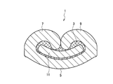
- Fig. 1 is a cross sectional view of an earth terminal according to a first embodiment.
- Fig. 2 is a cross sectional view of the earth terminal according to the first embodiment.
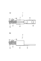
- Fig. 3(a) is a top view of the earth terminal according to the first embodiment and
- Fig. 3(b) is a side view of the earth terminal according to the first embodiment.
- Fig. 4(a) is the top view of the earth terminal according to the first embodiment and Fig. 4(b) is a side view of the earth terminal according to the first embodiment.
- Fig. 5 is a cross sectional view of the earth terminal according to the first embodiment.
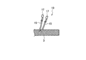
- Fig. 6 is a side view of a cable to which the earth terminal is connected.
- Fig. 1 is a cross sectional view of an earth terminal according to a first embodiment.
- Fig. 2 is a cross sectional view of the earth terminal according to the first embodiment.
- Fig. 3(a) is a top view of the earth terminal according to the first embodiment
- FIG. 7(a) is a side view of the cable to which the earth terminal according to a second embodiment is connected and Fig. 7(b) is cross sectional view of the earth terminal according to the second embodiment.
- Fig. 8 is a cross sectional view of the earth terminal according to a third embodiment.
- An earth terminal 1 according to the first embodiment is connected to a shield 3 made of a fibrous conductor and implements earthing.
- the earth terminal 1 includes a bottom wall 5 on which a shield 3 is disposed, a pair of first and second crimp pieces 7, 9 provided to be integrated with the bottom wall 5 and crimped to the shield 3, and a return piece 11 provided by folding back the bottom wall 5, and configured to allow a crimping force, which is applied to the shield 3 by disposing the shield 3 at least between the bottom wall 5 and the return piece 11 and crimping the pair of crimping pieces 7, 9, to escape in a widthwise direction of the bottom wall 5.
- the shield 3 to which the earth terminal 1 is connected serves as a part of components of the cable 13.
- the cable 13 includes two electric cables 15 each having a conductor core covered with an insulating coating, and the shield 3 for covering the outer periphery of the two electric cables 15. Further, although not illustrated, the outer periphery of the shield 3 is covered with an insulating coating.
- the end portion of each of the two electric cables 15 has the insulating coating ripped off and is electrically connected with a connection terminal 17 for connection with an electric part and the like. The two electric cables 15 are pulled outwardly from a midway portion of the shield 3.
- the shield 3 is made of a plastic fibrous conductor which is made by subjecting a polymeric fibrous material to an electroless plating treatment and the like to thereby make the polymeric material conductive.
- the earth terminal 1 is electrically connected to an end portion of the shield 3. Connecting the earth terminal 1 to the earth can implement earthing of the shield 3.
- the earth terminal 1 is formed by folding a plate-like conductive material and includes the bottom wall 5, the pair of first and second crimp pieces 7, 9, and the return piece 11.
- the bottom wall 5 extends in the longitudinal direction of the shield 3.
- the end portion of the shield 3 is disposed on the bottom wall 5.
- a earthing portion 19 is formed at an end portion of the bottom wall 5, and allows the earth terminal 1 to be subjected to earthing.
- the pair of first and second crimp pieces 7, 9 are disposed as an integral member continuous with the bottom wall 5.
- the pair of first and second crimp pieces 7, 9 respectively extend upward from the bottom wall 5 on both sides in the widthwise direction of the bottom wall 5 and extend in the longitudinal direction of the shield 3.
- the pair of first and second crimp pieces 7, 9 are so crimped, by a jig (not illustrated), as to have their end portions abut on each other to thereby fix the shield 3, and electrically connect the shield 3 with the earth terminal 1.
- the return piece 1 is interposed between the pair of first and second crimp pieces 7, 9 and the bottom wall 5.
- the return piece 11 is provided in a form of a U-like shape in a cross section by cutting out a center portion of the bottom wall 5 where the pair of crimp pieces 7, 9 are positioned and then by implementing a folding process such that the thus cut-out portion is parallel to an upper face of the bottom wall 5.
- the shield 3 is inserted to the return piece 11 and crimped by the pair of crimp pieces 7, 9.
- the return piece 11 since the return piece 11 is provided widely in the widthwise direction perpendicular to the longitudinal direction of the shield 3, the crimping force of the pair of crimp pieces 7, 9 which is applied to the shield 3 in a vertical direction is dispersed in the widthwise direction. Therefore, the shield 3 can be gradually compressed by expanding the shield 3 in the widthwise direction.
- the shield 3, the bottom wall 5, the pair of crimp pieces 7, 9 and the return piece 11 can be closely contact each other while preventing the shield 3 from being damaged.
- the return piece 11 can prevent the crimping force of the pair of crimp pieces 7, 9 from being locally applied to the shield 3, making it possible to improve conduction reliability between the earth terminal 1 and the shield 3.
- a method of assembling the earth terminal 1 to the shield 3 will be set froth as below. First, the shield 3 is caused to be inserted to the return piece 11 in such a manner as to cover the return piece 11. Then, the end portions of the pair of first and second crimp pieces 7, 9 are so crimped, by the jig, as to abut on each other, and then the shield 3 is fixed to the earth terminal 1, to thereby complete the assembling operation.
- the earth terminal 1 includes the return piece 11 which is provided by folding back the bottom wall 5, and the return piece 11 is configured to allow a crimping force, which is applied to the shield 3 by disposing the shield 3 at least between the bottom wall 5 and the return piece 11 and crimping the pair of crimping pieces 7, 9, to escape in the widthwise direction of the bottom wall 5. Therefore, the crimping force of the pair of first and second crimp pieces 7, 9 which is applied to the shield 3 can be dispersed, thus making it possible to prevent the shield 3 from being damaged.
- the crimping force of the pair of first and second crimp pieces 7, 9 which is applied to the shield 3 can be alleviated, making it possible to stabilize the conduction between the earth terminal 1 and the shield 3.
- the shield 3 is disposed between the return piece 11 and the bottom wall 5, and the return piece 11 and the bottom wall 5 are so crimped as to approach each other, and the end portion side of each of the pair of crimp pieces 7, 9 (one side only illustrated) crimps the return piece 11.
- the end portion of the shield 3 connected to the earth terminal 101 is so smashed as to be smaller in the thickness direction and is inserted between the return piece 11 and the bottom wall 5.
- the return piece 11 and the bottom wall 5 are so crimped, by the jig (not illustrated), as to approach each other.
- the shield 3 is sandwiched by the return piece 11 and the bottom wall 5 and is temporarily fixed, and the shield 3 and the earth terminal 101 are electrically connected with each other.
- the return piece 11 In the crimping operation between the return piece 11 and the bottom wall 5, since the return piece 11 is in a form of a flat plate formed widely in the widthwise direction, the return piece 11 presses the shield 3 with the flat face, thus preventing the crimping force from being locally applied to the shield 3.
- crimping the pair of first and second crimp pieces 7, 9 by the jig implements the crimping operation with the end portion side of each of the pair of first and second crimp pieces 7, 9 pressing the upper face of the return piece 11.
- the crimping force of the pair of first and second crimp pieces 7, 9 is caused to be locally applied to the upper face of the return 11, since the return piece 11 presses the shield 3 with its flat face
- the crimping force of the pair of first and second crimp pieces 7, 9 is not locally exerted to the shield 3.
- crimping the pair of first and second crimp pieces 7, 9 fully fixes the shield 3 to the earth terminal 101, thereby making it possible to stabilize the conduction between the shield 3 and the earth terminal 101. Further, by crimping the pair of first and second crimp pieces 7, 9 after the return piece 11 and the bottom wall 5 are crimped, the shield 3 is crimped gradually. Therefore, it is possible to alleviate the load applied to the shield 3 made of the fibrous conductor.
- a method of assembling the earth terminal 101 to the shield 3 will be set froth as below.
- the thickness of the shield 3 is to be formed thin such that the shield 3 can be inserted between the return piece 11 and the bottom wall 5.
- the thus formed shield 3 is inserted between the return piece 11 and the bottom wall 5, and then the return piece 11 and the bottom piece 5 are so crimped, by the jig, as to approach each other.
- the pair of first and second crimp pieces 7, 9 are crimped by the jig, thus fixing the shield 3 to the earth terminal 101, to thereby complete the assembling operation.
- each of the pair of first and second crimp pieces 7, 9 crimps the return piece 11 after the shield 3 disposed between the return piece 11 and the bottom wall 5 is crimped by the return piece 11 and the bottom wall 5. Therefore, the crimping force of the pair of first and second crimp pieces 7, 9 is not directly exerted to the shield 3, making it possible to alleviate the load applied to the shield 3 at the time of crimping operation. In addition, crimping the return piece 11 and the bottom wall 5 can securely hold the shield 3. (Third Embodiment)
- the second crimp piece 9 is so crimped as to be parallel to an opposing face of the return piece 11 while the first crimp piece 7 is so crimped as to overlap with the second crimp piece 9.
- the second crimp piece 9 is so crimped, by the jig (not illustrated), as to be parallel to an upper face of the return piece 11 as an opposing face, and then the first crimp piece 7 is so crimped, by the jig, as to overlap with the upper face of the second crimp piece 9.
- the end portions of the pair of first and second crimp pieces 7, 9 are so made as not to press the shield 3 (or the upper face of the return piece 11), thus making it possible to prevent the crimping force from being locally applied to the shield 3.
- a method of assembling the earth terminal 201 to the shield 3 will be set froth as below.
- the shield 3 is caused to be inserted to the return piece 11 (or, the shield 3 is inserted between the return piece 11 and the bottom wall 5).
- the second crimp piece 9 is so crimped, by the jig, as to be parallel to the upper face of the return piece 11.
- the first crimp piece 7 is so crimped, by the jig, as to overlap with the second crimp piece 9, to thereby fix the shield 3 to the earth terminal 201, thus completing the assembly.
- the first crimp piece 7 is so crimped as to overlap with the second crimp piece 9.
- the crimping force of the pair of the first and second crimp pieces 7, 9 is not locally applied to the shield 3, thus making it possible to prevent the shield 3 from being damaged.
- the earth terminal according to each embodiment has the return piece in a form of plate or column, however, the shape of the return piece is not limited to these, but the return piece may have any configuration provided that such configuration allows the crimping force of the pair of the crimp pieces to escape in the widthwise direction.
- an earth terminal capable of alleviating a crimping force of a pair of crimp pieces which is applied to a shield and capable of stabilizing the conduction between the shield and the earth terminal.
Landscapes
- Connections Effected By Soldering, Adhesion, Or Permanent Deformation (AREA)
- Details Of Connecting Devices For Male And Female Coupling (AREA)
Abstract
An earth terminal (1) to be connected to a shield (3) made of a fibrous conductor for implementing earthing includes: a bottom wall (5) on which the shield (3) is disposed; a pair of crimp pieces (7, 9) provided to be integrated with the bottom wall (5) and to be crimped to the shield (3); and a return piece (11) provided by folding back a part of the bottom wall (5), the return piece (11) configured to have the shield (3) disposed at least between the bottom wall (5) and the return piece (11), and configured to allow a crimping force, which is applied to the shield (3) with the crimp pieces (7, 9) crimped, to escape in a widthwise direction of the bottom wall (5).
Description
The present invention relates to an earth terminal.
As a conventional earth terminal to be connected to a shield made of fibrous conductor for implementing earthing, one that includes a bottom wall on which a braid provided within a cable as a shield is disposed, a braid crimp portion as a pair of crimp pieces that is integrated with the bottom wall and adapted to crimp the braid, and a connection piece whose distal end is inserted between an inner insulating layer and the braid of the cable from the end portion of the cable such that the braid is sandwiched between the connection piece and end portions of the pair of crimp portions is known (see PTL 1).
According to the conventional earth terminal, a retaining portion for preventing the connection piece from being displaced toward the conductor core at the time of crimping operation is provided to protrude on an inner face of the braid crimp portion, preventing the inner insulating layer from being smashed by preventing the connection piece from being displaced at the time of crimping operation, thus preventing the high frequency characteristics of the cable from being damaged by the crimping connection.
Incidentally, according to the above conventional earth terminal, the conductor core and the inner insulating layer that covers the conductor core are pulled outward from the end portion of the shield, a connection terminal is inserted to the conductor core such that the conventional earth terminal covers the connection terminal, and the connection piece of the conventional earth terminal is inserted between the inner insulating layer and the shield.
Contrary to the above, there may be a case in which the inner insulating layer and the conductor core are pulled outwardly from the midway of the shield and an earth terminal is connected only to the shield for implementing earthing. In this case, a drain wire and the like connected to the earth terminal is connected to the shield by soldering.
However, connecting the drain wire to the shield by the soldering may cause a high possibility that the connection is released when an external force and the like is applied to the drain wire and it also has difficulty in controlling conditions such as temperature and time for a fair quality production.
Contrary to the above, it is conceivable to crimp the pair of crimp pieces of the earth terminal directly to the shield. In this case, however, the crimping force of the pair of crimp pieces which is applied to the shield is so large that the shield may be damaged.
It is therefore an object of the present invention to provide an earth terminal capable of alleviating a crimping force of a pair of crimp pieces which is applied to a shield and capable of stabilizing the conduction between the shield and the earth terminal.
According to a first aspect of the present invention, an earth terminal to be connected to a shield made of a fibrous conductor for implementing earthing, includes: a bottom wall on which the shield is disposed; a pair of crimp pieces provided to be integrated with the bottom wall and crimped to the shield; and
a return piece provided by folding back a part of the bottom wall, the return peace configured to have the shield disposed at least between the bottom wall and the return piece, and configured to allow a crimping force, which is applied to the shield with the crimp pieces crimped, to escape in a widthwise direction of the bottom wall.
a return piece provided by folding back a part of the bottom wall, the return peace configured to have the shield disposed at least between the bottom wall and the return piece, and configured to allow a crimping force, which is applied to the shield with the crimp pieces crimped, to escape in a widthwise direction of the bottom wall.
With the above structure, the crimping force of the crimp pieces which is applied to the shield can be dispersed. Therefore, the shield can be prevented from being damaged.
Thus, the crimping force of the crimp pieces which is applied to the shield can be alleviated, thus making it possible to stabilize the conduction between the shield and the earth terminal.
The shield may be disposed between the return piece and the bottom wall, the return piece and the bottom wall may be so crimped as to approach each other, and an end portion side of each of the crimp pieces may crimp the return piece.
With the above structure, the crimping force of the crimp pieces is not directly exerted to the shield. This makes it possible to alleviate the load applied to the shield at the time of crimping operation. In addition, crimping the return piece and the bottom wall can securely hold the shield.
One of the crimp pieces may be so crimped as to be parallel to an opposing face of the return piece, and the other of the crimp pieces may be so crimped as to overlap with the one of the crimp pieces.
With the above structure, the crimping force of the crimp pieces is not locally applied to the shield. Thus, the shield can be prevented from being damaged.
The first aspect of the present invention can bring about such an effect that it is possible to provide the earth terminal capable of alleviating the crimping force of the crimp pieces which is applied to the shield and capable of stabilizing the conduction between the shield and the earth terminal.
Referring to Figs. 1 to 8, an earth terminal according to each embodiment of the present invention will be set forth.
(First Embodiment)
(First Embodiment)
An explanation will be made regarding a first embodiment referring to Figs. 1 to 6.
An earth terminal 1 according to the first embodiment is connected to a shield 3 made of a fibrous conductor and implements earthing.
The earth terminal 1 includes a bottom wall 5 on which a shield 3 is disposed, a pair of first and second crimp pieces 7, 9 provided to be integrated with the bottom wall 5 and crimped to the shield 3, and a return piece 11 provided by folding back the bottom wall 5, and configured to allow a crimping force, which is applied to the shield 3 by disposing the shield 3 at least between the bottom wall 5 and the return piece 11 and crimping the pair of crimping pieces 7, 9, to escape in a widthwise direction of the bottom wall 5.
As illustrated in Fig. 6, the shield 3 to which the earth terminal 1 is connected serves as a part of components of the cable 13. The cable 13 includes two electric cables 15 each having a conductor core covered with an insulating coating, and the shield 3 for covering the outer periphery of the two electric cables 15. Further, although not illustrated, the outer periphery of the shield 3 is covered with an insulating coating. The end portion of each of the two electric cables 15 has the insulating coating ripped off and is electrically connected with a connection terminal 17 for connection with an electric part and the like. The two electric cables 15 are pulled outwardly from a midway portion of the shield 3.
The shield 3 is made of a plastic fibrous conductor which is made by subjecting a polymeric fibrous material to an electroless plating treatment and the like to thereby make the polymeric material conductive. The earth terminal 1 is electrically connected to an end portion of the shield 3. Connecting the earth terminal 1 to the earth can implement earthing of the shield 3.
As illustrated in Figs. 1 to 5, the earth terminal 1 is formed by folding a plate-like conductive material and includes the bottom wall 5, the pair of first and second crimp pieces 7, 9, and the return piece 11. The bottom wall 5 extends in the longitudinal direction of the shield 3. The end portion of the shield 3 is disposed on the bottom wall 5. A earthing portion 19 is formed at an end portion of the bottom wall 5, and allows the earth terminal 1 to be subjected to earthing. On both sides in the widthwise direction of the bottom wall 5, the pair of first and second crimp pieces 7, 9 are disposed as an integral member continuous with the bottom wall 5.
The pair of first and second crimp pieces 7, 9 respectively extend upward from the bottom wall 5 on both sides in the widthwise direction of the bottom wall 5 and extend in the longitudinal direction of the shield 3. The pair of first and second crimp pieces 7, 9 are so crimped, by a jig (not illustrated), as to have their end portions abut on each other to thereby fix the shield 3, and electrically connect the shield 3 with the earth terminal 1. The return piece 1 is interposed between the pair of first and second crimp pieces 7, 9 and the bottom wall 5.
The return piece 11 is provided in a form of a U-like shape in a cross section by cutting out a center portion of the bottom wall 5 where the pair of crimp pieces 7, 9 are positioned and then by implementing a folding process such that the thus cut-out portion is parallel to an upper face of the bottom wall 5. The shield 3 is inserted to the return piece 11 and crimped by the pair of crimp pieces 7, 9. In this case, since the return piece 11 is provided widely in the widthwise direction perpendicular to the longitudinal direction of the shield 3, the crimping force of the pair of crimp pieces 7, 9 which is applied to the shield 3 in a vertical direction is dispersed in the widthwise direction. Therefore, the shield 3 can be gradually compressed by expanding the shield 3 in the widthwise direction. Thus, the shield 3, the bottom wall 5, the pair of crimp pieces 7, 9 and the return piece 11 can be closely contact each other while preventing the shield 3 from being damaged. The return piece 11 can prevent the crimping force of the pair of crimp pieces 7, 9 from being locally applied to the shield 3, making it possible to improve conduction reliability between the earth terminal 1 and the shield 3.
A method of assembling the earth terminal 1 to the shield 3 will be set froth as below. First, the shield 3 is caused to be inserted to the return piece 11 in such a manner as to cover the return piece 11. Then, the end portions of the pair of first and second crimp pieces 7, 9 are so crimped, by the jig, as to abut on each other, and then the shield 3 is fixed to the earth terminal 1, to thereby complete the assembling operation.
The earth terminal 1 includes the return piece 11 which is provided by folding back the bottom wall 5, and the return piece 11 is configured to allow a crimping force, which is applied to the shield 3 by disposing the shield 3 at least between the bottom wall 5 and the return piece 11 and crimping the pair of crimping pieces 7, 9, to escape in the widthwise direction of the bottom wall 5. Therefore, the crimping force of the pair of first and second crimp pieces 7, 9 which is applied to the shield 3 can be dispersed, thus making it possible to prevent the shield 3 from being damaged.
Thus, according to the earth terminal 1, the crimping force of the pair of first and second crimp pieces 7, 9 which is applied to the shield 3 can be alleviated, making it possible to stabilize the conduction between the earth terminal 1 and the shield 3.
(Second Embodiment)
(Second Embodiment)
An explanation will be made regarding a second embodiment referring to Fig. 7.
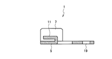
With an earth terminal 101 according to the second embodiment, the shield 3 is disposed between the return piece 11 and the bottom wall 5, and the return piece 11 and the bottom wall 5 are so crimped as to approach each other, and the end portion side of each of the pair of crimp pieces 7, 9 (one side only illustrated) crimps the return piece 11.
Note that, the same reference numerals or signs will be used for the structure same as that of the first embodiment and therefore the explanation about the structure and function of the second embodiment will be omitted by referring to those of the first embodiment, however, the effect brought about by the second embodiment is substantially the same as that according to the first embodiment.
As illustrated in Fig. 7, the end portion of the shield 3 connected to the earth terminal 101 is so smashed as to be smaller in the thickness direction and is inserted between the return piece 11 and the bottom wall 5. With the shield 3 inserted between the return piece 11 and the bottom wall 5, the return piece 11 and the bottom wall 5 are so crimped, by the jig (not illustrated), as to approach each other. By the above crimping operation, the shield 3 is sandwiched by the return piece 11 and the bottom wall 5 and is temporarily fixed, and the shield 3 and the earth terminal 101 are electrically connected with each other. In the crimping operation between the return piece 11 and the bottom wall 5, since the return piece 11 is in a form of a flat plate formed widely in the widthwise direction, the return piece 11 presses the shield 3 with the flat face, thus preventing the crimping force from being locally applied to the shield 3.
With the shield 3 temporarily fixed by the return piece 11 and the bottom wall 5, crimping the pair of first and second crimp pieces 7, 9 by the jig implements the crimping operation with the end portion side of each of the pair of first and second crimp pieces 7, 9 pressing the upper face of the return piece 11. Though the crimping force of the pair of first and second crimp pieces 7, 9 is caused to be locally applied to the upper face of the return 11, since the return piece 11 presses the shield 3 with its flat face Thus, the crimping force of the pair of first and second crimp pieces 7, 9 is not locally exerted to the shield 3. In this way, crimping the pair of first and second crimp pieces 7, 9 fully fixes the shield 3 to the earth terminal 101, thereby making it possible to stabilize the conduction between the shield 3 and the earth terminal 101. Further, by crimping the pair of first and second crimp pieces 7, 9 after the return piece 11 and the bottom wall 5 are crimped, the shield 3 is crimped gradually. Therefore, it is possible to alleviate the load applied to the shield 3 made of the fibrous conductor.
A method of assembling the earth terminal 101 to the shield 3 will be set froth as below. First, the thickness of the shield 3 is to be formed thin such that the shield 3 can be inserted between the return piece 11 and the bottom wall 5. Then, the thus formed shield 3 is inserted between the return piece 11 and the bottom wall 5, and then the return piece 11 and the bottom piece 5 are so crimped, by the jig, as to approach each other. Then, the pair of first and second crimp pieces 7, 9 are crimped by the jig, thus fixing the shield 3 to the earth terminal 101, to thereby complete the assembling operation.
With the earth terminal 101, the end portion side of each of the pair of first and second crimp pieces 7, 9 crimps the return piece 11 after the shield 3 disposed between the return piece 11 and the bottom wall 5 is crimped by the return piece 11 and the bottom wall 5. Therefore, the crimping force of the pair of first and second crimp pieces 7, 9 is not directly exerted to the shield 3, making it possible to alleviate the load applied to the shield 3 at the time of crimping operation. In addition, crimping the return piece 11 and the bottom wall 5 can securely hold the shield 3.
(Third Embodiment)
(Third Embodiment)
An explanation will be made regarding a third embodiment referring to Fig. 8.
With an earth terminal 201 according to the third embodiment, the second crimp piece 9 is so crimped as to be parallel to an opposing face of the return piece 11 while the first crimp piece 7 is so crimped as to overlap with the second crimp piece 9.
Note that, the same reference numerals or signs will be used for the structure same as that of the first embodiment and therefore the explanation about the structure and function of the third embodiment will be omitted by referring to those of the first embodiment, however, the effect brought about by the third embodiment is substantially the same as that according to the first embodiment.
As illustrated in Fig. 8, with respect to the pair of first and second crimp pieces 7, 9, after the shield 3 is inserted to the return piece 11 (or, as illustrated in Fig. 7, after the shield 3 is inserted between the return piece 11 and the bottom wall 5), the second crimp piece 9 is so crimped, by the jig (not illustrated), as to be parallel to an upper face of the return piece 11 as an opposing face, and then the first crimp piece 7 is so crimped, by the jig, as to overlap with the upper face of the second crimp piece 9. By crimping the pair of first and second crimp pieces 7, 9 in the above manner, the end portions of the pair of first and second crimp pieces 7, 9 are so made as not to press the shield 3 (or the upper face of the return piece 11), thus making it possible to prevent the crimping force from being locally applied to the shield 3.
Further, with respect to crimping of the pair of first and second crimp pieces 7, 9, it is possible to form for example the return piece 11 columnar and make the second crimp piece 9 crimped along a curve as the opposing face of the return piece 11. In this case, it is possible to disperse the crimping force of the pair of first and second crimp pieces 7, 9 more in the widthwise direction along the curve.
A method of assembling the earth terminal 201 to the shield 3 will be set froth as below. First, the shield 3 is caused to be inserted to the return piece 11 (or, the shield 3 is inserted between the return piece 11 and the bottom wall 5). Then, the second crimp piece 9 is so crimped, by the jig, as to be parallel to the upper face of the return piece 11. Then, the first crimp piece 7 is so crimped, by the jig, as to overlap with the second crimp piece 9, to thereby fix the shield 3 to the earth terminal 201, thus completing the assembly.
With the earth terminal 201, after the second crimp piece 9 is so crimped as to be parallel to the opposing face of the return piece 11, the first crimp piece 7 is so crimped as to overlap with the second crimp piece 9. As such, the crimping force of the pair of the first and second crimp pieces 7, 9 is not locally applied to the shield 3, thus making it possible to prevent the shield 3 from being damaged.
Further, the earth terminal according to each embodiment has the return piece in a form of plate or column, however, the shape of the return piece is not limited to these, but the return piece may have any configuration provided that such configuration allows the crimping force of the pair of the crimp pieces to escape in the widthwise direction.
It is possible to provide an earth terminal capable of alleviating a crimping force of a pair of crimp pieces which is applied to a shield and capable of stabilizing the conduction between the shield and the earth terminal.
Claims (3)
- An earth terminal to be connected to a shield made of a fibrous conductor for implementing earthing, comprising:
a bottom wall on which the shield is disposed;
a pair of crimp pieces provided to be integrated with the bottom wall and to be crimped to the shield; and
a return piece provided by folding back a part of the bottom wall, the return peace configured to have the shield disposed at least between the bottom wall and the return piece, and configured to allow a crimping force, which is applied to the shield with the crimp pieces crimped, to escape in a widthwise direction of the bottom wall. - The earth terminal according to claim 1, wherein
the shield is disposed between the return piece and the bottom wall,
the return piece and the bottom wall are so crimped as to approach each other, and
an end portion side of each of the crimp pieces crimps the return piece. - The earth terminal according to claim 1, wherein
one of the crimp pieces is so crimped as to be parallel to an opposing face of the return piece, and
the other of the crimp pieces is so crimped as to overlap with the one of the crimp pieces.
Applications Claiming Priority (2)
| Application Number | Priority Date | Filing Date | Title |
|---|---|---|---|
| JP2011-175712 | 2011-08-11 | ||
| JP2011175712A JP2013038046A (en) | 2011-08-11 | 2011-08-11 | Ground terminal |
Publications (1)
| Publication Number | Publication Date |
|---|---|
| WO2013021561A1 true WO2013021561A1 (en) | 2013-02-14 |
Family
ID=46758985
Family Applications (1)
| Application Number | Title | Priority Date | Filing Date |
|---|---|---|---|
| PCT/JP2012/004716 Ceased WO2013021561A1 (en) | 2011-08-11 | 2012-07-24 | Earth terminal |
Country Status (2)
| Country | Link |
|---|---|
| JP (1) | JP2013038046A (en) |
| WO (1) | WO2013021561A1 (en) |
Cited By (1)
| Publication number | Priority date | Publication date | Assignee | Title |
|---|---|---|---|---|
| US10103454B2 (en) | 2013-04-03 | 2018-10-16 | Yazaki Corporation | Structure and method for connecting terminal |
Citations (6)
| Publication number | Priority date | Publication date | Assignee | Title |
|---|---|---|---|---|
| US2789279A (en) * | 1953-08-07 | 1957-04-16 | Controls Company | Electrical connection and method of making the same |
| US5180884A (en) * | 1991-02-19 | 1993-01-19 | Champlain Cable Corporation | Shielded wire and cable |
| US5342996A (en) * | 1991-11-26 | 1994-08-30 | Sumitomo Wiring Systems, Ltd. | Inter-connecting terminal |
| US20040203286A1 (en) | 2003-04-14 | 2004-10-14 | Yazaki Corporation | Coaxial cable shielding terminal |
| US20060128223A1 (en) * | 2004-12-01 | 2006-06-15 | Yazaki Corporation | Shielded cable-grounding structure |
| US20100035487A1 (en) * | 2008-08-08 | 2010-02-11 | Sumitomo Wiring Systems, Ltd. | Terminal fitting and a wire connected with a terminal fitting |
-
2011
- 2011-08-11 JP JP2011175712A patent/JP2013038046A/en not_active Withdrawn
-
2012
- 2012-07-24 WO PCT/JP2012/004716 patent/WO2013021561A1/en not_active Ceased
Patent Citations (6)
| Publication number | Priority date | Publication date | Assignee | Title |
|---|---|---|---|---|
| US2789279A (en) * | 1953-08-07 | 1957-04-16 | Controls Company | Electrical connection and method of making the same |
| US5180884A (en) * | 1991-02-19 | 1993-01-19 | Champlain Cable Corporation | Shielded wire and cable |
| US5342996A (en) * | 1991-11-26 | 1994-08-30 | Sumitomo Wiring Systems, Ltd. | Inter-connecting terminal |
| US20040203286A1 (en) | 2003-04-14 | 2004-10-14 | Yazaki Corporation | Coaxial cable shielding terminal |
| US20060128223A1 (en) * | 2004-12-01 | 2006-06-15 | Yazaki Corporation | Shielded cable-grounding structure |
| US20100035487A1 (en) * | 2008-08-08 | 2010-02-11 | Sumitomo Wiring Systems, Ltd. | Terminal fitting and a wire connected with a terminal fitting |
Cited By (1)
| Publication number | Priority date | Publication date | Assignee | Title |
|---|---|---|---|---|
| US10103454B2 (en) | 2013-04-03 | 2018-10-16 | Yazaki Corporation | Structure and method for connecting terminal |
Also Published As
| Publication number | Publication date |
|---|---|
| JP2013038046A (en) | 2013-02-21 |
Similar Documents
| Publication | Publication Date | Title |
|---|---|---|
| KR20130014419A (en) | Wire cable assembly and methods of making that have a crimp connection that contains a pair of humps and a groove disposed therebetween to reduce broadcast rf energy therefrom | |
| US7368664B2 (en) | Shielded cable-grounding structure | |
| JP5688242B2 (en) | Shield wire ground wire connection structure | |
| US7803008B2 (en) | Press-clamping structure and press-clamping terminal | |
| US9431720B2 (en) | Connecting structure and connecting method of flat circuit body and terminal | |
| US9325089B2 (en) | Connecting structure and connecting method of flat circuit body and terminal | |
| JP6053920B2 (en) | Connector waterproof structure | |
| EP3573186B1 (en) | Terminal crimping method and terminal crimping structure | |
| CN104348038B (en) | Coaxial electric connector | |
| JP2018045762A (en) | Crimp terminal | |
| US20140033520A1 (en) | Crimping jig | |
| WO2010024032A1 (en) | Terminal metal fitting, method of manufacturing cable with terminal metal fitting, and terminal-crimping mold | |
| JP2015041509A (en) | Conduction path and electric wire | |
| JP2014044844A (en) | Conductor connection structure | |
| JP4640986B2 (en) | Cable connector and cable connection method | |
| JP2010067478A (en) | Terminal fitting, and electric wire with terminal fitting | |
| JP5146759B2 (en) | Terminal fitting, electric wire with terminal fitting, and manufacturing method of electric wire with terminal fitting | |
| KR102513547B1 (en) | Coil end connecting structure | |
| JP2019040829A (en) | Electrical wire | |
| JP6858639B2 (en) | Plug-in terminal device and switch | |
| JP5902414B2 (en) | Manufacturing method of terminal crimped wire | |
| KR100993098B1 (en) | Fixing crimp band, method for joining shielded connector and bulk knitted shield using same, shielded connector structure | |
| KR20110009894A (en) | Electrical terminal | |
| JP2013038046A (en) | Ground terminal | |
| JP6573074B2 (en) | Coaxial cable connector device |
Legal Events
| Date | Code | Title | Description |
|---|---|---|---|
| 121 | Ep: the epo has been informed by wipo that ep was designated in this application |
Ref document number: 12753244 Country of ref document: EP Kind code of ref document: A1 |
|
| NENP | Non-entry into the national phase |
Ref country code: DE |
|
| 122 | Ep: pct application non-entry in european phase |
Ref document number: 12753244 Country of ref document: EP Kind code of ref document: A1 |