EP3573186B1 - Terminal crimping method and terminal crimping structure - Google Patents
Terminal crimping method and terminal crimping structure Download PDFInfo
- Publication number
- EP3573186B1 EP3573186B1 EP19169700.2A EP19169700A EP3573186B1 EP 3573186 B1 EP3573186 B1 EP 3573186B1 EP 19169700 A EP19169700 A EP 19169700A EP 3573186 B1 EP3573186 B1 EP 3573186B1
- Authority
- EP
- European Patent Office
- Prior art keywords
- electric wire
- terminal
- cylinder portion
- fixing cylinder
- crimp
- Prior art date
- Legal status (The legal status is an assumption and is not a legal conclusion. Google has not performed a legal analysis and makes no representation as to the accuracy of the status listed.)
- Active
Links
- 238000002788 crimping Methods 0.000 title claims description 78
- 238000000034 method Methods 0.000 title claims description 19
- 239000004020 conductor Substances 0.000 claims description 54
- 238000012986 modification Methods 0.000 description 11
- 230000004048 modification Effects 0.000 description 11
- RYGMFSIKBFXOCR-UHFFFAOYSA-N Copper Chemical compound [Cu] RYGMFSIKBFXOCR-UHFFFAOYSA-N 0.000 description 6
- 229910000881 Cu alloy Inorganic materials 0.000 description 6
- 229910052802 copper Inorganic materials 0.000 description 6
- 239000010949 copper Substances 0.000 description 6
- 230000000694 effects Effects 0.000 description 5
- 230000003247 decreasing effect Effects 0.000 description 4
- 239000012212 insulator Substances 0.000 description 4
- 239000000463 material Substances 0.000 description 4
- 239000011347 resin Substances 0.000 description 3
- 229920005989 resin Polymers 0.000 description 3
- 238000010586 diagram Methods 0.000 description 2
- 238000003780 insertion Methods 0.000 description 2
- 230000037431 insertion Effects 0.000 description 2
- 239000002184 metal Substances 0.000 description 2
- 229910052751 metal Inorganic materials 0.000 description 2
- 239000007769 metal material Substances 0.000 description 2
- 238000009954 braiding Methods 0.000 description 1
- 230000005855 radiation Effects 0.000 description 1
Images


Classifications
-
- H—ELECTRICITY
- H01—ELECTRIC ELEMENTS
- H01R—ELECTRICALLY-CONDUCTIVE CONNECTIONS; STRUCTURAL ASSOCIATIONS OF A PLURALITY OF MUTUALLY-INSULATED ELECTRICAL CONNECTING ELEMENTS; COUPLING DEVICES; CURRENT COLLECTORS
- H01R4/00—Electrically-conductive connections between two or more conductive members in direct contact, i.e. touching one another; Means for effecting or maintaining such contact; Electrically-conductive connections having two or more spaced connecting locations for conductors and using contact members penetrating insulation
- H01R4/10—Electrically-conductive connections between two or more conductive members in direct contact, i.e. touching one another; Means for effecting or maintaining such contact; Electrically-conductive connections having two or more spaced connecting locations for conductors and using contact members penetrating insulation effected solely by twisting, wrapping, bending, crimping, or other permanent deformation
- H01R4/18—Electrically-conductive connections between two or more conductive members in direct contact, i.e. touching one another; Means for effecting or maintaining such contact; Electrically-conductive connections having two or more spaced connecting locations for conductors and using contact members penetrating insulation effected solely by twisting, wrapping, bending, crimping, or other permanent deformation by crimping
- H01R4/20—Electrically-conductive connections between two or more conductive members in direct contact, i.e. touching one another; Means for effecting or maintaining such contact; Electrically-conductive connections having two or more spaced connecting locations for conductors and using contact members penetrating insulation effected solely by twisting, wrapping, bending, crimping, or other permanent deformation by crimping using a crimping sleeve
-
- H—ELECTRICITY
- H01—ELECTRIC ELEMENTS
- H01R—ELECTRICALLY-CONDUCTIVE CONNECTIONS; STRUCTURAL ASSOCIATIONS OF A PLURALITY OF MUTUALLY-INSULATED ELECTRICAL CONNECTING ELEMENTS; COUPLING DEVICES; CURRENT COLLECTORS
- H01R4/00—Electrically-conductive connections between two or more conductive members in direct contact, i.e. touching one another; Means for effecting or maintaining such contact; Electrically-conductive connections having two or more spaced connecting locations for conductors and using contact members penetrating insulation
- H01R4/10—Electrically-conductive connections between two or more conductive members in direct contact, i.e. touching one another; Means for effecting or maintaining such contact; Electrically-conductive connections having two or more spaced connecting locations for conductors and using contact members penetrating insulation effected solely by twisting, wrapping, bending, crimping, or other permanent deformation
- H01R4/18—Electrically-conductive connections between two or more conductive members in direct contact, i.e. touching one another; Means for effecting or maintaining such contact; Electrically-conductive connections having two or more spaced connecting locations for conductors and using contact members penetrating insulation effected solely by twisting, wrapping, bending, crimping, or other permanent deformation by crimping
- H01R4/183—Electrically-conductive connections between two or more conductive members in direct contact, i.e. touching one another; Means for effecting or maintaining such contact; Electrically-conductive connections having two or more spaced connecting locations for conductors and using contact members penetrating insulation effected solely by twisting, wrapping, bending, crimping, or other permanent deformation by crimping for cylindrical elongated bodies, e.g. cables having circular cross-section
-
- H—ELECTRICITY
- H01—ELECTRIC ELEMENTS
- H01R—ELECTRICALLY-CONDUCTIVE CONNECTIONS; STRUCTURAL ASSOCIATIONS OF A PLURALITY OF MUTUALLY-INSULATED ELECTRICAL CONNECTING ELEMENTS; COUPLING DEVICES; CURRENT COLLECTORS
- H01R43/00—Apparatus or processes specially adapted for manufacturing, assembling, maintaining, or repairing of line connectors or current collectors or for joining electric conductors
- H01R43/04—Apparatus or processes specially adapted for manufacturing, assembling, maintaining, or repairing of line connectors or current collectors or for joining electric conductors for forming connections by deformation, e.g. crimping tool
- H01R43/048—Crimping apparatus or processes
-
- H—ELECTRICITY
- H01—ELECTRIC ELEMENTS
- H01R—ELECTRICALLY-CONDUCTIVE CONNECTIONS; STRUCTURAL ASSOCIATIONS OF A PLURALITY OF MUTUALLY-INSULATED ELECTRICAL CONNECTING ELEMENTS; COUPLING DEVICES; CURRENT COLLECTORS
- H01R9/00—Structural associations of a plurality of mutually-insulated electrical connecting elements, e.g. terminal strips or terminal blocks; Terminals or binding posts mounted upon a base or in a case; Bases therefor
- H01R9/03—Connectors arranged to contact a plurality of the conductors of a multiconductor cable, e.g. tapping connections
- H01R9/05—Connectors arranged to contact a plurality of the conductors of a multiconductor cable, e.g. tapping connections for coaxial cables
- H01R9/0518—Connection to outer conductor by crimping or by crimping ferrule
Definitions
- the present invention relates to a terminal crimping method and a terminal crimping structure.
- JP 2017 147419 A discloses that an electric wire comprises conductors and an insulator.
- the braided wire that covers the electric wire is folded back at a crimped portion of a shield terminal and covered with a crimp sleeve that is caulked.
- a fixed mold is used for caulking the crimp sleeve.
- the fixed mold has a lower mold and an upper mold, which comprise an indent forming protrusion at facing positions, respectively.
- pressing projections provided at opposing places of each die are bitten into a terminal to increase a crimping force with an electric wire.
- a part of a conductor of the electric wire may be damaged when the pressing projections are bitten into the terminal by abutting the dies on each other.
- One or more embodiments provide a terminal crimping method and a terminal crimping structure capable of firmly crimping a terminal while reducing damage to a conductor of an electric wire as much as possible.
- a terminal crimping method according to the invention is characterized in the following (1) to (2).
- a terminal crimping method includes covering an end portion of an electric wire with a fixing cylinder portion of a terminal, caulking and crimping the fixing cylinder portion by a pair of dies including pressing projections each having a flat shape in which a length in one axial direction is longer than a length in the other axial direction orthogonal to the one axial direction in a plan view, and caulking the fixing cylinder portion by the pressing projections to form crimp recess portions, in the caulking and crimping the fixing cylinder portion, wherein the fixing cylinder portion is caulked by the dies such that a longitudinal direction of each of the pressing projections which is the one axial direction, is aligned in an orthogonal direction which is orthogonal to an axis direction of the electric wire in which the terminal is crimped.
- the electric wire includes a shield conductor formed of a braid.
- the terminal includes a crimp cylinder portion through which the electric wire is inserted and a fixing member having the fixing cylinder portion.
- the fixing cylinder portion is caulked by the dies, in a state that the shield conductor which is folded back is disposed between the crimp cylinder portion and the fixing cylinder portion of the fixing member.
- a pressing projection provided in each die to increase a crimping force of a caulking portion is formed in a flat shape in which a length in one axial direction is longer than a length in the other axial direction orthogonal to the one axial direction in plan view.
- a longitudinal direction of the crimp recess portion to be formed in the fixing cylinder portion can be aligned in the direction orthogonal to the axis of the electric wire.
- a terminal crimping structure according to the invention is characterized in the following (3) to (4).
- a terminal crimping structure in an aspect (3), includes an electric wire and a terminal.
- the terminal includes a fixing cylinder portion which covers an end portion of the electric wire.
- the fixing cylinder portion is caulked and crimped.
- Crimp recess portions having a flat shape in which a length in one axial direction is longer than a length in other axial direction orthogonal to the one axial direction in plan view are formed in the fixing cylinder portion which is caulked, wherein a longitudinal direction of each of the crimp recess portions which is the one axial direction, is aligned in an orthogonal direction which is orthogonal to an axis direction of the electric wire in which the terminal is crimped.
- the electric wire includes a shield conductor formed of a braid.
- the terminal includes a crimp cylinder portion through which the electric wire is inserted and a fixing member having the fixing cylinder portion.
- the fixing cylinder portion is caulked, in a state that the shield conductor which is folded back is disposed between the crimp cylinder portion and the fixing cylinder portion of the fixing member.
- a crimp recess portion is formed and a crimping force of a caulking portion is increased.
- the crimp recess portion is formed in a flat shape in which a length in one axial direction is longer than a length in the other axial direction orthogonal to the one axial direction in plan view. That is, an area of the crimp recess portion is increased, and even when a depth dimension of the crimp recess portion is decreased, a sufficient crimping force is secured. Accordingly, it is possible to reduce stress concentration when the crimp recess portion is formed and to reduce damage to a conductor of an electric wire.
- a longitudinal direction of the crimp recess portion formed in a fixing cylinder portion is aligned in a direction orthogonal to an axis of the electric wire.
- a terminal crimping method and a terminal crimping structure capable of firmly crimping a terminal while reducing damage to a conductor of an electric wire as much as possible.
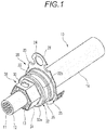
- Fig. 1 is a perspective view of an end portion of an electric wire to which a terminal is crimped for explaining a terminal crimping structure according to a first embodiment.
- Fig. 2 is a cross-sectional view taken along an axis of the electric wire to which the terminal is crimped for explaining the terminal crimping structure according to the first embodiment.
- Fig. 3 is a cross-sectional view taken along line A-A in Fig. 2 .
- the crimping structure according to the first embodiment is a structure in which a terminal 20 is crimped and fixed to an electric wire 10.
- the terminal 20 is provided with a fixing member 30 and is crimped and fixed to the electric wire 10 through the fixing member 30.
- the electric wire 10 is a shield electric wire formed of a coaxial cable including a central conductor 11, an insulator 12, a shield conductor 13, and a sheath 14.
- the central conductor 11 is formed of, for example, a stranded wire formed by stranding element wires of copper or a copper alloy.
- the insulator 12 is formed of a resin material having insulating properties and is provided to cover the periphery of the central conductor 11.
- the shield conductor 13 is, for example, a braid formed by braiding element wires of copper or a copper alloy and is provided to cover the periphery of the insulator 12.
- the sheath 14 is formed of a resin material having insulating properties and is provided to cover the periphery of the shield conductor 13.
- the central conductor 11 and the shield conductor 13 are exposed.
- the terminal 20 is mounted on an end portion of the sheath 14.
- the shield conductor 13 exposed from the sheath 14 is folded back and covered.
- the fixing member 30 is mounted on the portion where the shield conductor 13 is folded back and covered. The fixing member 30 is mounted from a distal end side of the electric wire 10.
- the terminal 20 is a shield terminal to be electrically connected to the shield conductor 13 of the electric wire 10.
- the terminal 20 is formed by pressing a conductive metal plate of copper, a copper alloy, or the like, and includes a crimp cylinder portion 21, a large diameter cylinder portion 22, a step portion 25, and a plate-like portion 23.
- the crimp cylinder portion 21 is fixed to the end portion of the inserted electric wire 10.
- the large diameter cylinder portion 22 is formed to have a larger diameter than the crimp cylinder portion 21 and is provided on the rear end side of the crimp cylinder portion 21.
- the step portion 25 is formed to have a larger diameter than the large diameter cylinder portion 22 and is provided on the rear end side of the large diameter cylinder portion 22.
- the plate-like portion 23 protrudes outward in a radial direction on the rear end side of the step portion 25.
- the plate-like portion 23 is provided with a fixing plate portion 26 provided with an insertion hole 24 at a part thereof.
- the fixing member 30 is formed by pressing a conductive metal plate of copper, a copper alloy, or the like and includes a fixing cylinder portion 31 and a flange portion 32.
- the fixing cylinder portion 31 is fixed to the crimp cylinder portion 21 of the terminal 20 covered with the shield conductor 13.
- the fixing cylinder portion 31 is formed in a cylindrical shape.
- the flange portion 32 includes a flange plate portion 32a extending outward in the radial direction from the cylindrically formed fixing cylinder portion 31, and an engaging cylinder portion 32b extending from an outer edge of the flange plate portion 32a to the rear end side.
- the engaging cylinder portion 32b of the flange portion 32 is formed to have a larger diameter than the fixing cylinder portion 31, and is fitted to the large diameter cylinder portion 22 of the terminal 20 from the distal end side.
- an annular recess portion 35 is formed on the outer periphery thereof from the step portion 25 and the flange portion 32 of the fixing member 30.
- a seal member (not illustrated) formed in an annular shape is accommodated.
- the fixing cylinder portion 31 of the fixing member 30 is caulked together with the crimp cylinder portion 21 of the terminal 20 to have a hexagonal cross section.
- the crimp cylinder portion 21 of the terminal 20 the shield conductor 13, and the fixing cylinder portion 31 of the fixing member 30 are crimped and fixed.
- crimp recess portions 33 are formed on two opposite surfaces of the six surfaces.
- Figs. 4A to 4C are views illustrating a shape of the crimp recess portion
- Fig. 4A is a plan view
- Fig. 4B is a cross-sectional view taken along a direction orthogonal to an axis of the electric wire
- Fig. 4C is a cross-sectional view taken along the axis of the electric wire.
- the crimp recess portion 33 has a flat shape in which the length in one axial direction is longer than the length in the other axial direction orthogonal to the one axial direction in plan view.
- the planar shape of the crimp recess portion 33 is formed in an oval shape which is long in a direction orthogonal to the axis of the electric wire 10 in plan view.
- the cross-sectional shape of the crimp recess portion 33 along a direction orthogonal to the axis of the electric wire 10 is formed in a concave shape in which both end portions 33a are formed in a circular arc shape, and the both end portions 33a having a circular arc shape are connected on a linear bottom portion 33b.
- the cross-sectional shape of the crimp recess portion 33 along the axis of the electric wire 10 is formed in a semicircular shape.
- the terminal 20 provided at the end portion of the electric wire 10 is connected to a case formed of a conductive metal material such as an inverter, a motor, or a battery. Specifically, the terminal 20 is inserted into a mounting hole of the case, a screw inserted into the insertion hole 24 formed in the fixing plate portion 26 of the plate-like portion 23 is screwed into a screw hole of the case, and the terminal is fixed such that the terminal is electrically connected to the case.
- a conductive metal material such as an inverter, a motor, or a battery.
- the shield conductor 13 of the electric wire 10 is electrically connected to the case, and a shielding effect is obtained. Therefore, influence of external noise such as electromagnetic waves is reduced and leakage of radiation noise such as electromagnetic waves from the electric wire 10 to the outside is reduced.
- Figs. 5A to 5C are views for explaining a procedure of crimping the terminal on the end portion of the electric wire
- Figs. 5A to 5C are perspective views illustrating the end portion of the electric wire, respectively.
- Figs. 6A and 6B are perspective views for explaining a step of crimping the terminal to the end portion of the electric wire
- Figs. 6A and 6B are perspective views illustrating the end portion of the electric wire, respectively.
- Figs. 7A and 7B are views for explaining a die for crimping the terminal to the end portion of the electric wire
- Fig. 7A is a perspective view of the die
- Fig. 7B is a schematic configuration diagram of a crimping place of the electric wire by a pair of dies;
- the end portion of the electric wire 10 is inserted into the terminal 20 in which the crimp cylinder portion 21 is formed in a cylindrical shape.
- the shield conductor 13 is exposed.
- the shield conductor 13 is widened and the shield conductor 13 is folded back to cover the outer periphery of the crimp cylinder portion 21 of the terminal 20.
- the fixing member 30 in which the fixing cylinder portion 31 is formed in a cylindrical shape is inserted and fitted from the end portion of the electric wire 10 and the fixing cylinder portion 31 of the fixing member 30 is fitted to the crimp cylinder portion 21 covered with the shield conductor 13.
- the crimp cylinder portion 21 of the terminal 20 to which the fixing cylinder portion 31 of the fixing member 30 is fitted is crimped by abutting a pair of dies 40.
- the dies 40 have trapezoidal caulking recess portions 41 formed by bisecting a hexagon on the abutting side of each other. That is, a hexagonal caulking space portion formed by the caulking recess portions 41 of each die 40 is formed by abutting the dies 40 on each other.
- a pressing projection 42 having a projecting dimension D1 is formed on a bottom portion 41a forming the caulking recess portion 41 of each die 40.
- the pressing projection 42 has a flat shape in which the length in one axial direction is longer than the length in the other axial direction orthogonal to the one axial direction in plan view.
- the pressing projection 42 is formed in an oval shape which is long in the direction orthogonal to the axis of the electric wire 10 crimped in a planar shape in plan view.
- the cross-sectional shape of the pressing projection 42 along the direction orthogonal to the axis of the electric wire 10 is a convex shape in which both end portions 42a are formed in a circular arc shape and the both end portion 42 having a circular arc shape are connected at a linear top portion 42b.
- the cross-sectional shape of the pressing projection 42 along the axis of the electric wire 10 is formed in a semicircular shape.
- the fixing cylinder portion 31 and the crimp cylinder portion 21 are caulked by the caulking recess portions 41 of the dies 40 through the shield conductor 13 and are formed in a hexagonal shape.
- the terminal 20 is crimped and fixed to the end portion of the electric wire 10
- the shield conductor 13 of the electric wire 10 is interposed between the crimp cylinder portion 21 of the terminal 20 and the fixing cylinder portion 31, and thus the terminal 20 and the shield conductor 13 are electrically connected.
- the pressing projections 42 formed in the bottom portions 41a of the caulking recess portions 41 of each die 40 are bitten into the fixing cylinder portion 31 to form the crimp recess portions 33.
- the crimping force at the crimping place is increased.
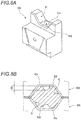
- Figs. 8A and 8B are views for explaining a die according to Reference Example 1 in which a terminal is crimped to an end portion of an electric wire
- Fig. 8A is a perspective view of the die
- Fig. 8B is a schematic configuration view of the crimping place of the electric wire by a pair of the dies.
- Each die 40A is provided with a pressing projection 42A having a projecting dimension D2 which is larger than the projecting dimension D1 on the bottom portion 41a forming the caulking recess portion 41.
- the pressing projection 42A is formed in a plane circular shape.
- a cross-sectional shape along the direction orthogonal to the axis of the electric wire 10 and a cross-sectional shape along the axis of the electric wire 10 are formed in a circular arc shape. That is, the pressing projection 42A is a projection projecting hemispherically.
- the pressing projections 42A are bitten into the fixing member 30 and thus the crimping force at the crimping place is increased.
- the planar shape of the pressing projections 42A of these dies 40A is small and the projecting dimension D2 is large, the pressing projections 42A are locally bitten into the fixing member 30. In this case, a great force is applied to the shield conductor 13 of the electric wire 10 and there is concern that the wires in the shield conductor 13 may be damaged.
- the pressing projection 42 provided in the die 40 to increase the crimping force of the caulking portion is formed in a flat shape in which the length in one axial direction is longer than the length in the other axial direction orthogonal to the one axial direction in plan view.
- the area of the pressing projection 42 can be increased, and even when the projecting dimension of the pressing projection 42 is decreased, a sufficient crimping force can be secured. Accordingly, it is possible to reduce the stress concentration at the bitten place of the pressing projection 42 when the fixing cylinder portion 31 is caulked.
- the longitudinal direction of the crimp recess portion 33 to be formed in the fixing cylinder portion 31 can be aligned in the direction orthogonal to the axis of the electric wire 10.
- Figs. 9A to 9C are illustrating a shape of a crimp recess portion according to Modification Example 1
- Fig. 9A is a plan view
- Fig. 9B is a cross-sectional view taken along a direction orthogonal to an axis of an electric wire
- Fig. 9C is a cross-sectional view taken along the axis of the electric wire.
- the planar shape of the crimp recess portion 33 is formed in a rectangular shape which is long in the direction orthogonal to the axis of the electric wire 10 in plan view.
- the cross-sectional shape of the crimp recess portion 33 along the direction orthogonal to the axis of the electric wire 10 is formed in a concave shape in which both end portions 33a are inclined and the both end portions 33a formed by the inclined surfaces are connected on the linear bottom portion 33b.
- the cross-sectional shape of the crimp recess portion 33 along the axis of the electric wire 10 is formed in a triangular shape.
- Figs. 10A to 10C are illustrating a shape of a crimp recess portion according to Modification Example 2
- Fig. 10A is a plan view
- Fig. 10B is a cross-sectional view taken along a direction orthogonal to an axis of an electric wire
- Fig. 10C is a cross-sectional view taken along the axis of the electric wire.
- the planar shape of the crimp recess portion 33 is formed in a rectangular shape which is long in the direction orthogonal to the axis of the electric wire 10 in plan view.
- the cross-sectional shape of the crimp recess portion 33 along the direction orthogonal to the axis of the electric wire 10 is formed in a concave shape in which both end portions 33a are inclined and the both end portions 33a formed by the inclined surfaces are connected on the linear bottom portion 33b.
- the cross-sectional shape of the crimp recess portion 33 along the axis of the electric wire 10 is formed in a trapezoidal shape.
- the crimp recess portion 33 is formed in a flat shape in which the length in one axial direction is longer than the length in the other axial direction orthogonal to the one axial direction in plan view. That is, the area of the crimp recess portion 33 is increased, and even when the depth dimension of the crimp recess portion 33 is increased, a sufficient crimping force is secured. Accordingly, it is possible to reduce the stress concentration when the crimp recess portion 33 is formed and to reduce the damage to the shield conductor 13 of the electric wire 10.
- Fig. 11 is a perspective view of an end portion of an electric wire to which a terminal is crimped for explaining a terminal crimping structure according to the second embodiment.
- Fig. 12 is a cross-sectional view taken along an axis of the electric wire to which the terminal is crimped for explaining the terminal crimping structure according to the second embodiment.
- the crimping structure according to the second embodiment has a structure in which a terminal 60 is crimped and fixed to an electric wire 50.
- the electric wire 50 includes a conductor 51 and a sheath 54.
- the conductor 51 is formed of, for example, a stranded wire formed by stranding element wires of copper or a copper alloy.
- the sheath 54 is formed of a resin material having insulating properties and is provided to cover the periphery of the conductor 51.
- the conductor 51 is exposed. On the exposed conductor 51, a terminal 60 is mounted.
- the terminal 60 is formed of a conductive metal material such as copper or a copper alloy, and includes an electric connection portion 61 and a fixing cylinder portion 62.
- the electric connection portion 61 is a portion to be connected to the counterpart terminal.
- the fixing cylinder portion 62 is a portion to be connected to the conductor 51 of the electric wire 50.
- the fixing cylinder portion 62 of the terminal 60 is caulked to have a hexagonal cross section.
- the fixing cylinder portion 62 of the terminal 60 is crimped and fixed to an end portion of the conductor 51 exposed from the sheath 54.
- crimp recess portions 63 are formed on two opposite surfaces of the six surfaces.
- the planar shape of the crimp recess portion 63 is formed in a flat shape in which the length in one axial direction is longer than the length in the other axial direction orthogonal to the one axial direction in plan view. Specifically, the planar shape of the crimp recess portion 63 is formed in a rectangular shape which is long in the direction orthogonal to the axis of the electric wire 50 in plan view.
- the cross-sectional shape of the crimp recess portion 63 along the direction orthogonal to the axis of the electric wire 50 is formed in a concave shape in which both end portions 63a are inclined and the both end portions 63a formed by the inclined surfaces are connected on a linear bottom portion 63b.
- the cross-sectional shape of the crimp recess portion 63 along the axis of the electric wire 50 is formed in a trapezoidal shape.
- Figs. 13A to 13C are views for explaining a procedure of crimping a terminal on an end portion of an electric wire
- Figs. 13A to 13C are perspective views illustrating the end portion of the electric wire, respectively.
- the conductor 51 is exposed.
- the fixing cylinder portion 62 of the terminal 60 formed in a cylindrical shape is inserted and fitted to the end portion of the electric wire 50.
- the fixing cylinder portion 62 of the terminal 60 is caulked by a pair of dies 80.
- the dies 80 include trapezoidal caulking recess portions 81 formed by bisecting a hexagon on the abutting side of each other.
- pressing projections 82 are formed on bottom portions 81a forming the caulking recess portions 81 of each die 80.
- the pressing projection 82 has a flat shape in which the length in one axial direction is longer than the length in the other axial direction orthogonal to the one axial direction in plan view.
- the pressing projection 82 is formed in an oval shape which is long in the direction orthogonal to the axis of the electric wire 50 crimped in a planar shape in plan view, and the top portion is linearly formed.
- the cross-sectional shape of the pressing projection 82 along the axis of the electric wire 50 and the cross-sectional shape of the pressing projection along the direction orthogonal to the axis of the electric wire 50 are formed in a trapezoidal shape.
- the fixing cylinder portion 62 is caulked by the caulking recess portions 81 of the dies 80 and is formed in a hexagonal shape.
- the terminal 60 is crimped and fixed to the end portion of the electric wire 50 and the conductor 51 of the electric wire 50 and the terminal 60 are electrically connected.
- the pressing projections 82 formed in the bottom portions 81a of the caulking recess portions 81 of each die 80 are bitten into the fixing cylinder portion 62 to form the crimp recess portions 63.
- the crimping force at the crimping place is increased.
- the pressing projection 82 provided in the die 80 to increase the crimping force of the caulking portion is formed in a flat shape in which the length in one axial direction is longer than the length in the other axial direction orthogonal to the one axial direction in plan view.
- the area of the pressing projection 82 can be increased, and even when the projecting dimension of the pressing projection 82 is decreased, a sufficient crimping force can be secured. Accordingly, it is possible to reduce the stress concentration at the bitten place of the pressing projection 82 when the fixing cylinder portion 62 is caulked. Thus, it is possible to reduce damage to the conductor 51 of the electric wire 50 and to obtain a good shielding effect.
- Figs. 14A and 14B are views for explaining a crimping method and a crimping structure according to Reference Example 2, and Figs. 14A and 14B are perspective views illustrating an end portion of an electric wire, respectively.
- crimp recess portions 63A are formed on two opposite surfaces of the six surfaces.
- the planar shape of the crimp recess portion 63A is formed in a rectangular shape which is long along the axis of the electric wire 50 in plan view.
- the cross-sectional shape of the crimp recess portion 63A along the axis of the electric wire 50 is formed in a concave shape in which both end portions 63a are inclined and the both end portions 63a formed by the inclined surfaces are connected on the linear bottom portion 63b.
- the cross-sectional shape of the crimp recess portion 63A along the direction orthogonal to the axis of the electric wire 50 is formed in a trapezoidal shape.
- the fixing cylinder portion 62 of the terminal 60 is caulked using a pair of dies 80A.
- Each die 80A is provided with a pressing projection 82A on a bottom portion 81a of a caulking recess portion 81.
- the pressing projection 82A is formed in an oval shape which is long along the axis of the electric wire 50 crimped in a planar shape in plan view.
- the cross-sectional shape of the pressing projection 82A along the axis of the electric wire 50 and the cross-sectional shape of the pressing projection along the direction orthogonal to the axis of the electric wire 50 are formed in a trapezoid shape.
- the fixing cylinder portion 62 of the terminal 60 is caulked by the dies 80A each provided with the pressing projection 82A formed in an oval shape which is long along the axis of the electric wire 50 crimped in a planar shape in plan view. Then, the crimp recess portions 63A each of which is long along the axis of the electric wire 50 in plan view are formed in the fixing cylinder portion 62 of the terminal 60. Therefore, the length of the fixing cylinder portion 62 of the terminal 60 along the axis of the electric wire 50 has to be increased and the size of the terminal 60 becomes large.
- the longitudinal direction of the crimp recess portion 63 to be formed in the fixing cylinder portion 62 can be aligned in the direction orthogonal to the axis of the electric wire 50.
- the crimp recess portions 63 are formed on two opposite surfaces of six surface of the fixing cylinder portion 62 caulked to have a hexagonal cross section.
- the crimp recess portions 63 may be formed on all six surfaces of the fixing cylinder portion 62.
- the crimping force with the electric wire 50 can be further increased.
- the invention is not limited to the above-described embodiments and suitable modifications, improvements or the like can be made.
- the material, shape, dimension, number and arrangement of each component in the above-described embodiments are not limited but can be arbitrarily set, as long as they can achieve the invention.
Landscapes
- Engineering & Computer Science (AREA)
- Manufacturing & Machinery (AREA)
- Connections Effected By Soldering, Adhesion, Or Permanent Deformation (AREA)
- Manufacturing Of Electrical Connectors (AREA)
- Multi-Conductor Connections (AREA)
- Shielding Devices Or Components To Electric Or Magnetic Fields (AREA)
Description
- The present invention relates to a terminal crimping method and a terminal crimping structure.
- As a technology for crimping a terminal to an electric wire, for example, there has been known a technique of caulking and crimping a cylindrical terminal into which an electric wire is inserted to have a hexagonal cross section by abutting a pair of dies including a recess portion having a shape, in which a hexagonal cross section is bisected, on each other (see, for example, the patent document 1:
JP 2000 21543 A JP 2011 171057 A JP 2017 147419 A -
- [Patent Document 1]
JP 2000 21543 A - [Patent Document 2]
JP 2011 171057 A - According to a related art, pressing projections provided at opposing places of each die are bitten into a terminal to increase a crimping force with an electric wire. However, there is concern that a part of a conductor of the electric wire may be damaged when the pressing projections are bitten into the terminal by abutting the dies on each other.
- One or more embodiments provide a terminal crimping method and a terminal crimping structure capable of firmly crimping a terminal while reducing damage to a conductor of an electric wire as much as possible.
- In order to achieve the above-mentioned object, a terminal crimping method according to the invention is characterized in the following (1) to (2).
- In an aspect (1), a terminal crimping method includes covering an end portion of an electric wire with a fixing cylinder portion of a terminal, caulking and crimping the fixing cylinder portion by a pair of dies including pressing projections each having a flat shape in which a length in one axial direction is longer than a length in the other axial direction orthogonal to the one axial direction in a plan view, and caulking the fixing cylinder portion by the pressing projections to form crimp recess portions, in the caulking and crimping the fixing cylinder portion, wherein
the fixing cylinder portion is caulked by the dies such that a longitudinal direction of each of the pressing projections which is the one axial direction, is aligned in an orthogonal direction which is orthogonal to an axis direction of the electric wire in which the terminal is crimped. - In an aspect (2), the electric wire includes a shield conductor formed of a braid. The terminal includes a crimp cylinder portion through which the electric wire is inserted and a fixing member having the fixing cylinder portion. The fixing cylinder portion is caulked by the dies, in a state that the shield conductor which is folded back is disposed between the crimp cylinder portion and the fixing cylinder portion of the fixing member.
- According to the aspect (1), a pressing projection provided in each die to increase a crimping force of a caulking portion is formed in a flat shape in which a length in one axial direction is longer than a length in the other axial direction orthogonal to the one axial direction in plan view. Thus, an area of the pressing projection can be increased, and even when a projecting dimension of the pressing projection is decreased, a sufficient crimping force can be secured. Accordingly, it is possible to reduce stress concentration at a bitten place of the pressing projection when a fixing cylinder portion of a terminal is caulked. Thus, it is possible to reduce damage to a conductor of an electric wire.
- Moreover, according to the aspect (1), by caulking the fixing cylinder portion such that a longitudinal direction of the pressing projection is aligned in a direction orthogonal to an axis of the electric wire, a longitudinal direction of the crimp recess portion to be formed in the fixing cylinder portion can be aligned in the direction orthogonal to the axis of the electric wire. Thus, it is possible to make the terminal compact by reducing a length of the fixing cylinder portion of the terminal in an axial direction.
- According to the aspect (2), it is possible to reduce damage to a shield conductor formed of a braid and to obtain a good shielding effect.
- In order to achieve the above object, a terminal crimping structure according to the invention is characterized in the following (3) to (4).
- In an aspect (3), a terminal crimping structure includes an electric wire and a terminal. The terminal includes a fixing cylinder portion which covers an end portion of the electric wire. The fixing cylinder portion is caulked and crimped. Crimp recess portions having a flat shape in which a length in one axial direction is longer than a length in other axial direction orthogonal to the one axial direction in plan view are formed in the fixing cylinder portion which is caulked, wherein a longitudinal direction of each of the crimp recess portions which is the one axial direction, is aligned in an orthogonal direction which is orthogonal to an axis direction of the electric wire in which the terminal is crimped.
- In an aspect (4), the electric wire includes a shield conductor formed of a braid. The terminal includes a crimp cylinder portion through which the electric wire is inserted and a fixing member having the fixing cylinder portion. The fixing cylinder portion is caulked, in a state that the shield conductor which is folded back is disposed between the crimp cylinder portion and the fixing cylinder portion of the fixing member.
- According to the aspect (3), a crimp recess portion is formed and a crimping force of a caulking portion is increased. The crimp recess portion is formed in a flat shape in which a length in one axial direction is longer than a length in the other axial direction orthogonal to the one axial direction in plan view. That is, an area of the crimp recess portion is increased, and even when a depth dimension of the crimp recess portion is decreased, a sufficient crimping force is secured. Accordingly, it is possible to reduce stress concentration when the crimp recess portion is formed and to reduce damage to a conductor of an electric wire.
- Moreover, according to the aspect (3), a longitudinal direction of the crimp recess portion formed in a fixing cylinder portion is aligned in a direction orthogonal to an axis of the electric wire. Thus, it is possible to make a terminal compact by reducing a length of the fixing cylinder portion of the terminal in an axial direction.
- According to the aspect (5), it is possible to reduce damage to a shield conductor formed of a braid and to obtain a good shielding effect.
- According to one or more embodiments, it is possible to provide a terminal crimping method and a terminal crimping structure capable of firmly crimping a terminal while reducing damage to a conductor of an electric wire as much as possible.
- The invention has been described above briefly. The details of the invention will become more apparent by reading through a mode for carrying out the invention described below with reference to the accompanying drawings.
-
-
Fig. 1 is a perspective view of an end portion of an electric wire to which a terminal is crimped for explaining a terminal crimping structure according to a first embodiment; -
Fig. 2 is a cross-sectional view taken along an axis of the electric wire to which the terminal is crimped for explaining the terminal crimping structure according to the first embodiment; -
Fig. 3 is a cross-sectional view taken along line A-A inFig. 2 ; -
Figs. 4A to 4C are views illustrating a shape of a crimp recess portion, whereinFig. 4A is a plan view,Fig. 4B is a cross-sectional view taken along a direction orthogonal to an axis of the electric wire, andFig. 4C is a cross-sectional view taken along the axis of the electric wire; -
Figs. 5A to 5C are views for explaining a procedure of crimping a terminal on an end portion of an electric wire, and are perspective views illustrating the end portion of the electric wire, respectively; -
Figs. 6A and 6B are perspective views for explaining a step of crimping a terminal to an end portion of an electric wire, and are perspective views illustrating the end portion of the electric wire, respectively; -
Figs. 7A and 7B are views for explaining a die for crimping a terminal to an end portion of an electric wire, whereinFig. 7A is a perspective view of the die, andFig. 7B is a schematic configuration diagram of a crimping place of the electric wire by a pair of dies; -
Figs. 8A and 8B are views for explaining a die according to Reference Example 1 in which a terminal is crimped to an end portion of an electric wire, whereinFig. 8A is a perspective view of the die, andFig. 8B is a schematic configuration view of the crimping place of the electric wire by a pair of the dies; -
Figs. 9A to 9C are illustrating a shape of a crimp recess portion according to Modification Example 1, whereinFig. 9A is a plan view,Fig. 9B is a cross-sectional view taken along a direction orthogonal to an axis of an electric wire, andFig. 9C is a cross-sectional view taken along the axis of the electric wire; -
Figs. 10A to 10C are illustrating a shape of a crimp recess portion according to Modification Example 2,Fig. 10A is a plan view,Fig. 10B is a cross-sectional view taken along a direction orthogonal to an axis of an electric wire, andFig. 10C is a cross-sectional view taken along the axis of the electric wire; -
Fig. 11 is a perspective view of an end portion of an electric wire to which a terminal is crimped for explaining a terminal crimping structure according to a second embodiment; -
Fig. 12 is a cross-sectional view taken along an axis of the electric wire to which the terminal is crimped for explaining the terminal crimping structure according to the second embodiment; -
Figs. 13A to 13C are views for explaining a procedure of crimping a terminal on an end portion of an electric wire, and are perspective views illustrating the end portion of the electric wire, respectively; -
Figs. 14A and 14B are views for explaining a crimping method and a crimping structure according to Reference Example 2, and are perspective views illustrating an end portion of an electric wire, respectively; and -
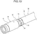
Fig. 15 is a perspective view of an end portion of an electric wire to which a terminal is crimped illustrating another example of a crimping structure of the terminal. - Hereinafter, examples of embodiments will be described with reference to the drawings.
- First, a terminal crimping method and a terminal crimping structure according to a first embodiment will be described.
-
Fig. 1 is a perspective view of an end portion of an electric wire to which a terminal is crimped for explaining a terminal crimping structure according to a first embodiment.Fig. 2 is a cross-sectional view taken along an axis of the electric wire to which the terminal is crimped for explaining the terminal crimping structure according to the first embodiment.Fig. 3 is a cross-sectional view taken along line A-A inFig. 2 . - As illustrated in
Figs. 1 to 3 , the crimping structure according to the first embodiment is a structure in which a terminal 20 is crimped and fixed to anelectric wire 10. The terminal 20 is provided with a fixingmember 30 and is crimped and fixed to theelectric wire 10 through the fixingmember 30. - The
electric wire 10 is a shield electric wire formed of a coaxial cable including acentral conductor 11, aninsulator 12, ashield conductor 13, and asheath 14. Thecentral conductor 11 is formed of, for example, a stranded wire formed by stranding element wires of copper or a copper alloy. Theinsulator 12 is formed of a resin material having insulating properties and is provided to cover the periphery of thecentral conductor 11. Theshield conductor 13 is, for example, a braid formed by braiding element wires of copper or a copper alloy and is provided to cover the periphery of theinsulator 12. Thesheath 14 is formed of a resin material having insulating properties and is provided to cover the periphery of theshield conductor 13. - At an end portion of the
electric wire 10, thecentral conductor 11 and theshield conductor 13 are exposed. The terminal 20 is mounted on an end portion of thesheath 14. In the portion where the terminal 20 is mounted, theshield conductor 13 exposed from thesheath 14 is folded back and covered. On the portion where theshield conductor 13 is folded back and covered, the fixingmember 30 is mounted. The fixingmember 30 is mounted from a distal end side of theelectric wire 10. - The terminal 20 is a shield terminal to be electrically connected to the
shield conductor 13 of theelectric wire 10. For example, the terminal 20 is formed by pressing a conductive metal plate of copper, a copper alloy, or the like, and includes acrimp cylinder portion 21, a largediameter cylinder portion 22, astep portion 25, and a plate-like portion 23. Thecrimp cylinder portion 21 is fixed to the end portion of the insertedelectric wire 10. The largediameter cylinder portion 22 is formed to have a larger diameter than thecrimp cylinder portion 21 and is provided on the rear end side of thecrimp cylinder portion 21. Thestep portion 25 is formed to have a larger diameter than the largediameter cylinder portion 22 and is provided on the rear end side of the largediameter cylinder portion 22. The plate-like portion 23 protrudes outward in a radial direction on the rear end side of thestep portion 25. The plate-like portion 23 is provided with a fixingplate portion 26 provided with aninsertion hole 24 at a part thereof. - For example, the fixing
member 30 is formed by pressing a conductive metal plate of copper, a copper alloy, or the like and includes a fixingcylinder portion 31 and aflange portion 32. The fixingcylinder portion 31 is fixed to thecrimp cylinder portion 21 of the terminal 20 covered with theshield conductor 13. In the fixingmember 30 before caulking, the fixingcylinder portion 31 is formed in a cylindrical shape. Theflange portion 32 includes aflange plate portion 32a extending outward in the radial direction from the cylindrically formed fixingcylinder portion 31, and anengaging cylinder portion 32b extending from an outer edge of theflange plate portion 32a to the rear end side. The engagingcylinder portion 32b of theflange portion 32 is formed to have a larger diameter than the fixingcylinder portion 31, and is fitted to the largediameter cylinder portion 22 of the terminal 20 from the distal end side. Thus, in the largediameter cylinder portion 22, anannular recess portion 35 is formed on the outer periphery thereof from thestep portion 25 and theflange portion 32 of the fixingmember 30. In theannular recess portion 35, a seal member (not illustrated) formed in an annular shape is accommodated. - The fixing
cylinder portion 31 of the fixingmember 30 is caulked together with thecrimp cylinder portion 21 of the terminal 20 to have a hexagonal cross section. Thus, in the portion of thesheath 14 at the end portion of theelectric wire 10, thecrimp cylinder portion 21 of the terminal 20, theshield conductor 13, and the fixingcylinder portion 31 of the fixingmember 30 are crimped and fixed. In the fixingcylinder portion 31 of the fixingmember 30 caulked to have a hexagonal cross section, crimprecess portions 33 are formed on two opposite surfaces of the six surfaces. -
Figs. 4A to 4C are views illustrating a shape of the crimp recess portion,Fig. 4A is a plan view,Fig. 4B is a cross-sectional view taken along a direction orthogonal to an axis of the electric wire, andFig. 4C is a cross-sectional view taken along the axis of the electric wire. - As illustrated in
Fig. 4A , thecrimp recess portion 33 has a flat shape in which the length in one axial direction is longer than the length in the other axial direction orthogonal to the one axial direction in plan view. Specifically, the planar shape of thecrimp recess portion 33 is formed in an oval shape which is long in a direction orthogonal to the axis of theelectric wire 10 in plan view. As illustrated inFig. 4B , the cross-sectional shape of thecrimp recess portion 33 along a direction orthogonal to the axis of theelectric wire 10 is formed in a concave shape in which both endportions 33a are formed in a circular arc shape, and the bothend portions 33a having a circular arc shape are connected on alinear bottom portion 33b. As illustrated inFig. 4C , the cross-sectional shape of thecrimp recess portion 33 along the axis of theelectric wire 10 is formed in a semicircular shape. - The terminal 20 provided at the end portion of the
electric wire 10 is connected to a case formed of a conductive metal material such as an inverter, a motor, or a battery. Specifically, the terminal 20 is inserted into a mounting hole of the case, a screw inserted into theinsertion hole 24 formed in the fixingplate portion 26 of the plate-like portion 23 is screwed into a screw hole of the case, and the terminal is fixed such that the terminal is electrically connected to the case. - When the terminal 20 is fixed to the case as such, the
shield conductor 13 of theelectric wire 10 is electrically connected to the case, and a shielding effect is obtained. Therefore, influence of external noise such as electromagnetic waves is reduced and leakage of radiation noise such as electromagnetic waves from theelectric wire 10 to the outside is reduced. - Next, the crimping method of caulking and crimping the terminal 20 to the
electric wire 10 will be described. -
Figs. 5A to 5C are views for explaining a procedure of crimping the terminal on the end portion of the electric wire, andFigs. 5A to 5C are perspective views illustrating the end portion of the electric wire, respectively.Figs. 6A and 6B are perspective views for explaining a step of crimping the terminal to the end portion of the electric wire, andFigs. 6A and 6B are perspective views illustrating the end portion of the electric wire, respectively.Figs. 7A and 7B are views for explaining a die for crimping the terminal to the end portion of the electric wire,Fig. 7A is a perspective view of the die, andFig. 7B is a schematic configuration diagram of a crimping place of the electric wire by a pair of dies; - As illustrated in
Fig. 5A , the end portion of theelectric wire 10 is inserted into the terminal 20 in which thecrimp cylinder portion 21 is formed in a cylindrical shape. As illustrated inFig. 5B , by subjecting theelectric wire 10 to a terminal treatment, theshield conductor 13 is exposed. As illustrated inFig. 5C , theshield conductor 13 is widened and theshield conductor 13 is folded back to cover the outer periphery of thecrimp cylinder portion 21 of the terminal 20. - As illustrated in
Fig. 6A , the fixingmember 30 in which thefixing cylinder portion 31 is formed in a cylindrical shape is inserted and fitted from the end portion of theelectric wire 10 and the fixingcylinder portion 31 of the fixingmember 30 is fitted to thecrimp cylinder portion 21 covered with theshield conductor 13. As illustrated inFig. 6B , thecrimp cylinder portion 21 of the terminal 20 to which thefixing cylinder portion 31 of the fixingmember 30 is fitted is crimped by abutting a pair of dies 40. - As illustrated in
Figs. 7A and 7B , the dies 40 have trapezoidalcaulking recess portions 41 formed by bisecting a hexagon on the abutting side of each other. That is, a hexagonal caulking space portion formed by thecaulking recess portions 41 of each die 40 is formed by abutting the dies 40 on each other. - On a
bottom portion 41a forming thecaulking recess portion 41 of each die 40, apressing projection 42 having a projecting dimension D1 is formed. Thepressing projection 42 has a flat shape in which the length in one axial direction is longer than the length in the other axial direction orthogonal to the one axial direction in plan view. Specifically, the pressingprojection 42 is formed in an oval shape which is long in the direction orthogonal to the axis of theelectric wire 10 crimped in a planar shape in plan view. The cross-sectional shape of thepressing projection 42 along the direction orthogonal to the axis of theelectric wire 10 is a convex shape in which both endportions 42a are formed in a circular arc shape and the bothend portion 42 having a circular arc shape are connected at a lineartop portion 42b. The cross-sectional shape of thepressing projection 42 along the axis of theelectric wire 10 is formed in a semicircular shape. - When the pair of dies 40 are abutted on each other with the
crimp cylinder portion 21, to which thefixing cylinder portion 31 of the fixingmember 30 is fitted, interposed therebetween, the fixingcylinder portion 31 and thecrimp cylinder portion 21 are caulked by thecaulking recess portions 41 of the dies 40 through theshield conductor 13 and are formed in a hexagonal shape. Thus, the terminal 20 is crimped and fixed to the end portion of theelectric wire 10, theshield conductor 13 of theelectric wire 10 is interposed between thecrimp cylinder portion 21 of the terminal 20 and the fixingcylinder portion 31, and thus the terminal 20 and theshield conductor 13 are electrically connected. Thepressing projections 42 formed in thebottom portions 41a of thecaulking recess portions 41 of each die 40 are bitten into the fixingcylinder portion 31 to form thecrimp recess portions 33. Thus, the crimping force at the crimping place is increased. - Here, Reference Example 1 will be described.
-
Figs. 8A and 8B are views for explaining a die according to Reference Example 1 in which a terminal is crimped to an end portion of an electric wire,Fig. 8A is a perspective view of the die, andFig. 8B is a schematic configuration view of the crimping place of the electric wire by a pair of the dies. - As illustrated in
Figs. 8A and 8B , in Reference Example 1, thecrimp cylinder portion 21 of the terminal 20, to which thefixing cylinder portion 31 of the fixingmember 30 is fitted, is caulked using a pair of dies 40A. Each die 40A is provided with apressing projection 42A having a projecting dimension D2 which is larger than the projecting dimension D1 on thebottom portion 41a forming thecaulking recess portion 41. Thepressing projection 42A is formed in a plane circular shape. In thepressing projection 42A, a cross-sectional shape along the direction orthogonal to the axis of theelectric wire 10 and a cross-sectional shape along the axis of theelectric wire 10 are formed in a circular arc shape. That is, thepressing projection 42A is a projection projecting hemispherically. - When the
crimp cylinder portion 21 of the terminal 20, to which thefixing cylinder portion 31 of the fixingmember 30 is fitted, is caulked using these dies 40A, thepressing projections 42A are bitten into the fixingmember 30 and thus the crimping force at the crimping place is increased. However, since the planar shape of thepressing projections 42A of these dies 40A is small and the projecting dimension D2 is large, thepressing projections 42A are locally bitten into the fixingmember 30. In this case, a great force is applied to theshield conductor 13 of theelectric wire 10 and there is concern that the wires in theshield conductor 13 may be damaged. - In contrast, according to the first embodiment, the pressing
projection 42 provided in the die 40 to increase the crimping force of the caulking portion is formed in a flat shape in which the length in one axial direction is longer than the length in the other axial direction orthogonal to the one axial direction in plan view. Thus, the area of thepressing projection 42 can be increased, and even when the projecting dimension of thepressing projection 42 is decreased, a sufficient crimping force can be secured. Accordingly, it is possible to reduce the stress concentration at the bitten place of thepressing projection 42 when the fixingcylinder portion 31 is caulked. Thus, it is possible to reduce damage to theshield conductor 13 formed of a braid of theelectric wire 10 and to obtain a good shielding effect. - By caulking the fixing
cylinder portion 31 such that the longitudinal direction of thepressing projection 42 is aligned in the direction orthogonal to the axis of theelectric wire 10, the longitudinal direction of thecrimp recess portion 33 to be formed in the fixingcylinder portion 31 can be aligned in the direction orthogonal to the axis of theelectric wire 10. Thus, it is possible to make the terminal 20 compact by reducing the length of the fixingcylinder portion 31 in the axial direction. - Here, modification examples of the
crimp recess portion 33 formed by the pressingprojection 42 of the die 40 will be described. -
Figs. 9A to 9C are illustrating a shape of a crimp recess portion according to Modification Example 1,Fig. 9A is a plan view,Fig. 9B is a cross-sectional view taken along a direction orthogonal to an axis of an electric wire, andFig. 9C is a cross-sectional view taken along the axis of the electric wire. - As illustrated in
Fig. 9A , in Modification Example 1, the planar shape of thecrimp recess portion 33 is formed in a rectangular shape which is long in the direction orthogonal to the axis of theelectric wire 10 in plan view. As illustrated inFig. 9B , the cross-sectional shape of thecrimp recess portion 33 along the direction orthogonal to the axis of theelectric wire 10 is formed in a concave shape in which both endportions 33a are inclined and the bothend portions 33a formed by the inclined surfaces are connected on thelinear bottom portion 33b. As illustrated inFig. 9C , the cross-sectional shape of thecrimp recess portion 33 along the axis of theelectric wire 10 is formed in a triangular shape. -
Figs. 10A to 10C are illustrating a shape of a crimp recess portion according to Modification Example 2,Fig. 10A is a plan view,Fig. 10B is a cross-sectional view taken along a direction orthogonal to an axis of an electric wire, andFig. 10C is a cross-sectional view taken along the axis of the electric wire. - As illustrated in
Fig. 10A , in Modification Example 2, the planar shape of thecrimp recess portion 33 is formed in a rectangular shape which is long in the direction orthogonal to the axis of theelectric wire 10 in plan view. As illustrated inFig. 10B , the cross-sectional shape of thecrimp recess portion 33 along the direction orthogonal to the axis of theelectric wire 10 is formed in a concave shape in which both endportions 33a are inclined and the bothend portions 33a formed by the inclined surfaces are connected on thelinear bottom portion 33b. As illustrated inFig. 10C , the cross-sectional shape of thecrimp recess portion 33 along the axis of theelectric wire 10 is formed in a trapezoidal shape. - Also in Modification Examples 1 and 2, the
crimp recess portion 33 is formed in a flat shape in which the length in one axial direction is longer than the length in the other axial direction orthogonal to the one axial direction in plan view. That is, the area of thecrimp recess portion 33 is increased, and even when the depth dimension of thecrimp recess portion 33 is increased, a sufficient crimping force is secured. Accordingly, it is possible to reduce the stress concentration when thecrimp recess portion 33 is formed and to reduce the damage to theshield conductor 13 of theelectric wire 10. - Next, a terminal crimping method and a terminal crimping structure of a according to a second embodiment will be described.
- The same components as those of the first embodiment are denoted by the same reference numerals, and description thereof is omitted.
-
Fig. 11 is a perspective view of an end portion of an electric wire to which a terminal is crimped for explaining a terminal crimping structure according to the second embodiment.Fig. 12 is a cross-sectional view taken along an axis of the electric wire to which the terminal is crimped for explaining the terminal crimping structure according to the second embodiment. - As illustrated in
Figs. 11 and 12 , the crimping structure according to the second embodiment has a structure in which a terminal 60 is crimped and fixed to anelectric wire 50. - The
electric wire 50 includes aconductor 51 and asheath 54. Theconductor 51 is formed of, for example, a stranded wire formed by stranding element wires of copper or a copper alloy. Thesheath 54 is formed of a resin material having insulating properties and is provided to cover the periphery of theconductor 51. - At the end portion of the
electric wire 50, theconductor 51 is exposed. On the exposedconductor 51, a terminal 60 is mounted. - For example, the terminal 60 is formed of a conductive metal material such as copper or a copper alloy, and includes an
electric connection portion 61 and a fixingcylinder portion 62. Theelectric connection portion 61 is a portion to be connected to the counterpart terminal. The fixingcylinder portion 62 is a portion to be connected to theconductor 51 of theelectric wire 50. - The fixing
cylinder portion 62 of the terminal 60 is caulked to have a hexagonal cross section. Thus, in theelectric wire 50, the fixingcylinder portion 62 of the terminal 60 is crimped and fixed to an end portion of theconductor 51 exposed from thesheath 54. In the fixingcylinder portion 62 caulked to have a hexagonal cross section, crimprecess portions 63 are formed on two opposite surfaces of the six surfaces. - The planar shape of the
crimp recess portion 63 is formed in a flat shape in which the length in one axial direction is longer than the length in the other axial direction orthogonal to the one axial direction in plan view. Specifically, the planar shape of thecrimp recess portion 63 is formed in a rectangular shape which is long in the direction orthogonal to the axis of theelectric wire 50 in plan view. The cross-sectional shape of thecrimp recess portion 63 along the direction orthogonal to the axis of theelectric wire 50 is formed in a concave shape in which both endportions 63a are inclined and the bothend portions 63a formed by the inclined surfaces are connected on alinear bottom portion 63b. The cross-sectional shape of thecrimp recess portion 63 along the axis of theelectric wire 50 is formed in a trapezoidal shape. - Next, the crimping method of caulking and crimping the fixing
cylinder portion 62 of the terminal 60 to theelectric wire 50 will be described. -
Figs. 13A to 13C are views for explaining a procedure of crimping a terminal on an end portion of an electric wire, andFigs. 13A to 13C are perspective views illustrating the end portion of the electric wire, respectively. - As illustrated in
Fig. 13A , by subjecting theelectric wire 50 to a terminal treatment, theconductor 51 is exposed. As illustrated inFig. 13B , the fixingcylinder portion 62 of the terminal 60 formed in a cylindrical shape is inserted and fitted to the end portion of theelectric wire 50. As illustrated inFig. 13C , the fixingcylinder portion 62 of the terminal 60 is caulked by a pair of dies 80. - The dies 80 include trapezoidal
caulking recess portions 81 formed by bisecting a hexagon on the abutting side of each other. Onbottom portions 81a forming thecaulking recess portions 81 of each die 80, pressingprojections 82 are formed. Thepressing projection 82 has a flat shape in which the length in one axial direction is longer than the length in the other axial direction orthogonal to the one axial direction in plan view. Specifically, the pressingprojection 82 is formed in an oval shape which is long in the direction orthogonal to the axis of theelectric wire 50 crimped in a planar shape in plan view, and the top portion is linearly formed. The cross-sectional shape of thepressing projection 82 along the axis of theelectric wire 50 and the cross-sectional shape of the pressing projection along the direction orthogonal to the axis of theelectric wire 50 are formed in a trapezoidal shape. - When the pair of dies 80 are abutted on each other with the fixing
cylinder portion 62 of the terminal 60, to which theconductor 51 of theelectric wire 50 is fitted, interposed therebetween, the fixingcylinder portion 62 is caulked by thecaulking recess portions 81 of the dies 80 and is formed in a hexagonal shape. Thus, the terminal 60 is crimped and fixed to the end portion of theelectric wire 50 and theconductor 51 of theelectric wire 50 and the terminal 60 are electrically connected. Thepressing projections 82 formed in thebottom portions 81a of thecaulking recess portions 81 of each die 80 are bitten into the fixingcylinder portion 62 to form thecrimp recess portions 63. Thus, the crimping force at the crimping place is increased. - According to the second embodiment like above, the pressing
projection 82 provided in the die 80 to increase the crimping force of the caulking portion is formed in a flat shape in which the length in one axial direction is longer than the length in the other axial direction orthogonal to the one axial direction in plan view. Thus, the area of thepressing projection 82 can be increased, and even when the projecting dimension of thepressing projection 82 is decreased, a sufficient crimping force can be secured. Accordingly, it is possible to reduce the stress concentration at the bitten place of thepressing projection 82 when the fixingcylinder portion 62 is caulked. Thus, it is possible to reduce damage to theconductor 51 of theelectric wire 50 and to obtain a good shielding effect. - Here, Reference Example 2 will be described.
-
Figs. 14A and 14B are views for explaining a crimping method and a crimping structure according to Reference Example 2, andFigs. 14A and 14B are perspective views illustrating an end portion of an electric wire, respectively. - As illustrated in
Fig. 14A , in Reference Example 2, in the fixingcylinder portion 62 caulked to have a hexagonal cross section, crimprecess portions 63A are formed on two opposite surfaces of the six surfaces. The planar shape of thecrimp recess portion 63A is formed in a rectangular shape which is long along the axis of theelectric wire 50 in plan view. The cross-sectional shape of thecrimp recess portion 63A along the axis of theelectric wire 50 is formed in a concave shape in which both endportions 63a are inclined and the bothend portions 63a formed by the inclined surfaces are connected on thelinear bottom portion 63b. The cross-sectional shape of thecrimp recess portion 63A along the direction orthogonal to the axis of theelectric wire 50 is formed in a trapezoidal shape. - In Reference Example 2, the fixing
cylinder portion 62 of the terminal 60 is caulked using a pair of dies 80A. Each die 80A is provided with apressing projection 82A on abottom portion 81a of acaulking recess portion 81. Thepressing projection 82A is formed in an oval shape which is long along the axis of theelectric wire 50 crimped in a planar shape in plan view. The cross-sectional shape of thepressing projection 82A along the axis of theelectric wire 50 and the cross-sectional shape of the pressing projection along the direction orthogonal to the axis of theelectric wire 50 are formed in a trapezoid shape. - When the fixing
cylinder portion 62 of the terminal 60 to which theconductor 51 of theelectric wire 50 is fitted is caulked by the dies 80A, thepressing projections 82A formed in thebottom portions 81a of thecaulking recess portions 81 of each die 80A are bitten into the fixingcylinder portion 62 and thecrimp recess portions 63A are formed. Thus, the crimping force at the crimping place is increased. - However, in Reference Example 2, the fixing
cylinder portion 62 of the terminal 60 is caulked by the dies 80A each provided with thepressing projection 82A formed in an oval shape which is long along the axis of theelectric wire 50 crimped in a planar shape in plan view. Then, thecrimp recess portions 63A each of which is long along the axis of theelectric wire 50 in plan view are formed in the fixingcylinder portion 62 of the terminal 60. Therefore, the length of the fixingcylinder portion 62 of the terminal 60 along the axis of theelectric wire 50 has to be increased and the size of the terminal 60 becomes large. - In contrast, according to the second embodiment, by caulking the fixing
cylinder portion 62 such that the longitudinal direction of thepressing projection 82 is aligned in the direction orthogonal to the axis of theelectric wire 50, the longitudinal direction of thecrimp recess portion 63 to be formed in the fixingcylinder portion 62 can be aligned in the direction orthogonal to the axis of theelectric wire 50. Thus, it is possible to make the terminal 60 compact by reducing the length of the fixingcylinder portion 62 in the axial direction. - In the second embodiment, the
crimp recess portions 63 are formed on two opposite surfaces of six surface of the fixingcylinder portion 62 caulked to have a hexagonal cross section. However, as illustrated inFig. 15 , thecrimp recess portions 63 may be formed on all six surfaces of the fixingcylinder portion 62. Thus, the crimping force with theelectric wire 50 can be further increased. - Incidentally, the invention is not limited to the above-described embodiments and suitable modifications, improvements or the like can be made. The material, shape, dimension, number and arrangement of each component in the above-described embodiments are not limited but can be arbitrarily set, as long as they can achieve the invention.
-
- 10, 50: electric wire
- 13: shield conductor
- 20, 60: terminal
- 21: crimp cylinder portion
- 30: fixing member
- 31, 62: fixing cylinder portion
- 33, 63: crimp recess portion
- 40, 80: die
- 42, 82: pressing projection
Claims (4)
- A terminal crimping method comprising:covering an end portion of an electric wire (10, 50) with a fixing cylinder portion (31, 62) of a terminal (20, 60);caulking and crimping the fixing cylinder portion (31, 62) by a pair of dies (40, 80) including pressing projections (42, 82) each having a flat shape in which a length in one axial direction is longer than a length in the other axial direction orthogonal to the one axial direction in a plan view; andcaulking the fixing cylinder portion (31, 62) by the pressing projections (42, 82) to form crimp recess portions (33, 63), in the caulking and crimping the fixing cylinder portion (31, 62),characterized in that the fixing cylinder portion (31, 62) is caulked by the dies (40, 80) such that a longitudinal direction of each of the pressing projections (42, 82) which is the one axial direction, is aligned in an orthogonal direction which is orthogonal to an axis direction of the electric wire (10, 50) in which the terminal (20, 60) is crimped.
- The terminal crimping method according to claim 1,
wherein the electric wire (10) includes a shield conductor (13) formed of a braid,
wherein the terminal (20) includes a crimp cylinder portion (21) through which the electric wire (10) is inserted and a fixing member (30) having the fixing cylinder portion (31), and
wherein the fixing cylinder portion (31) is caulked by the dies (40), in a state that the shield conductor (13) which is folded back is disposed between the crimp cylinder portion (21) and the fixing cylinder portion (31) of the fixing member (30). - A terminal crimping structure comprising:an electric wire (10, 50); anda terminal (20, 60),wherein the terminal (20, 60) includes a fixing cylinder portion (31, 62) which covers an end portion of the electric wire (10, 50),wherein the fixing cylinder portion (31, 62) is caulked and crimped, andwherein crimp recess portions (33, 63) having a flat shape in which a length in one axial direction is longer than a length in other axial direction orthogonal to the one axial direction in plan view are formed in the fixing cylinder portion (31, 62) which is caulked,characterized in that a longitudinal direction of each of the crimp recess portions (33, 63) which is the one axial direction, is aligned in an orthogonal direction which is orthogonal to an axis direction of the electric wire (10, 50) in which the terminal (20, 60) is crimped.
- The terminal crimping structure according to claim 3,
wherein the electric wire (10) includes a shield conductor (13) formed of a braid,
wherein the terminal (20) includes a crimp cylinder portion (21) through which the electric wire (10) is inserted and a fixing member (30) having the fixing cylinder portion (31), and
wherein the fixing cylinder portion (31) is caulked, in a state that the shield conductor (13) which is folded back is disposed between the crimp cylinder portion (21) and the fixing cylinder portion (31) of the fixing member (30).
Applications Claiming Priority (1)
| Application Number | Priority Date | Filing Date | Title |
|---|---|---|---|
| JP2018097222A JP6762338B2 (en) | 2018-05-21 | 2018-05-21 | Terminal crimping method and crimping structure |
Publications (2)
| Publication Number | Publication Date |
|---|---|
| EP3573186A1 EP3573186A1 (en) | 2019-11-27 |
| EP3573186B1 true EP3573186B1 (en) | 2020-09-16 |
Family
ID=66217858
Family Applications (1)
| Application Number | Title | Priority Date | Filing Date |
|---|---|---|---|
| EP19169700.2A Active EP3573186B1 (en) | 2018-05-21 | 2019-04-17 | Terminal crimping method and terminal crimping structure |
Country Status (4)
| Country | Link |
|---|---|
| US (1) | US10804665B2 (en) |
| EP (1) | EP3573186B1 (en) |
| JP (1) | JP6762338B2 (en) |
| CN (1) | CN110518432B (en) |
Families Citing this family (7)
| Publication number | Priority date | Publication date | Assignee | Title |
|---|---|---|---|---|
| DE102020101236A1 (en) | 2020-01-20 | 2021-07-22 | Te Connectivity Germany Gmbh | Arrangement, tooling and method for making such an arrangement |
| JP7074804B2 (en) * | 2020-06-19 | 2022-05-24 | 矢崎総業株式会社 | Cable assembly |
| CN112002469B (en) * | 2020-08-18 | 2022-02-11 | 昆山联滔电子有限公司 | Cable and processing method thereof |
| JP7197544B2 (en) | 2020-09-28 | 2022-12-27 | 矢崎総業株式会社 | Shielded wire manufacturing method, shielded wire with grounding member, and crimping device |
| US11791600B2 (en) | 2020-12-16 | 2023-10-17 | Aptiv Technologies Limited | Barrel crimp retention feature for connector with braided wire |
| US11462875B2 (en) * | 2020-12-16 | 2022-10-04 | Aptiv Technologies Limited | Barrel crimp retention feature for connector with braided wire |
| JP2023122883A (en) * | 2022-02-24 | 2023-09-05 | 住友電装株式会社 | Shield wire and manufacturing device for the same |
Family Cites Families (12)
| Publication number | Priority date | Publication date | Assignee | Title |
|---|---|---|---|---|
| JP2000021543A (en) * | 1998-07-06 | 2000-01-21 | Yazaki Corp | Dice for caulking terminal and its method |
| JP2007059304A (en) * | 2005-08-26 | 2007-03-08 | Auto Network Gijutsu Kenkyusho:Kk | Wire with terminal and its manufacturing method |
| JP2010251287A (en) * | 2009-03-23 | 2010-11-04 | Autonetworks Technologies Ltd | Method of manufacturing electric wire with terminal fitting |
| JP2011171057A (en) | 2010-02-17 | 2011-09-01 | Yazaki Corp | Crimping apparatus for shielded wire, and method for end-processing shielded wire |
| JP5686064B2 (en) * | 2011-07-26 | 2015-03-18 | 住友電装株式会社 | Crimping die and method for manufacturing electric wire with terminal |
| JP5830312B2 (en) * | 2011-09-05 | 2015-12-09 | 染矢電線株式会社 | Electric wire with terminal |
| JP6075968B2 (en) * | 2012-05-14 | 2017-02-08 | 矢崎総業株式会社 | Tubular braided caulking connection structure |
| JP5886161B2 (en) * | 2012-07-31 | 2016-03-16 | 矢崎総業株式会社 | Shield connector structure |
| FR2995459B1 (en) * | 2012-09-07 | 2014-10-10 | Mecatraction | METHOD FOR ASSEMBLING A CONNECTING DEVICE ON A TERMINAL STRIP DENUDE OF AN ELECTRIC CABLE AND ASSEMBLY COMPRISING SUCH A DEVICE ASSEMBLED SOLIDARILY ON SUCH A CABLE TRUNK |
| US10361527B2 (en) * | 2015-02-25 | 2019-07-23 | Te Connectivity Corporation | Electrical terminal and device for forming a terminal |
| JP6731744B2 (en) * | 2016-02-19 | 2020-07-29 | 矢崎総業株式会社 | Shield terminal connection method |
| JP6546627B2 (en) * | 2016-10-13 | 2019-07-17 | 矢崎総業株式会社 | Electric wire with terminal, manufacturing method of electric wire with terminal, and terminal crimping device |
-
2018
- 2018-05-21 JP JP2018097222A patent/JP6762338B2/en active Active
-
2019
- 2019-04-16 US US16/386,078 patent/US10804665B2/en active Active
- 2019-04-17 EP EP19169700.2A patent/EP3573186B1/en active Active
- 2019-04-19 CN CN201910318018.9A patent/CN110518432B/en active Active
Non-Patent Citations (1)
| Title |
|---|
| None * |
Also Published As
| Publication number | Publication date |
|---|---|
| JP6762338B2 (en) | 2020-09-30 |
| US20190356101A1 (en) | 2019-11-21 |
| EP3573186A1 (en) | 2019-11-27 |
| US10804665B2 (en) | 2020-10-13 |
| CN110518432A (en) | 2019-11-29 |
| JP2019204599A (en) | 2019-11-28 |
| CN110518432B (en) | 2021-03-05 |
Similar Documents
| Publication | Publication Date | Title |
|---|---|---|
| EP3573186B1 (en) | Terminal crimping method and terminal crimping structure | |
| EP3573185B1 (en) | Terminal crimping method and terminal crimping structure | |
| JP2019062732A (en) | Electrical contact device, electrical connection unit, and assembling method of electrical cable | |
| WO2009113686A1 (en) | Hoop material, method for manufacturing inner conductor terminal, and coaxial connector | |
| CN104541413A (en) | Shield connector structure | |
| JPH1022001A (en) | Processing structure for shielding layer of shielding wire | |
| JP7096123B2 (en) | Terminal connection structure of shielded wire | |
| JPH11144776A (en) | Structure and method of connecting connector for coaxial cable | |
| JP5059481B2 (en) | Shield connector | |
| US9431727B2 (en) | Terminal connection structure for electric wire | |
| JP2013062054A (en) | Connecting structure of coaxial cable and shield terminal, and connecting method of the same | |
| JP4503458B2 (en) | Shield wire ground connector and ground connection method | |
| JP5191822B2 (en) | Shield connector | |
| CN107431279A (en) | Single-core line and wirning harness | |
| JP2019200898A (en) | Shield connector | |
| JP3211232U (en) | Coaxial connector | |
| CN114284833B (en) | Method for producing a shielded wire, shielded wire with a grounding member, and clamping device | |
| JP7171293B2 (en) | shield connector | |
| JP2019040829A (en) | Electric wire | |
| US20230163539A1 (en) | Shielded terminal | |
| US11316287B2 (en) | Connection device and electric wire connection structure | |
| JP3693973B2 (en) | L-shaped plug and its assembly method | |
| US20220029373A1 (en) | Method for manufacturing an electrical connector for a multi-wire electrical cable | |
| JP4959488B2 (en) | Connector connection structure of multi-core coaxial cable | |
| JP2011049061A (en) | Coaxial cable connector |
Legal Events
| Date | Code | Title | Description |
|---|---|---|---|
| PUAI | Public reference made under article 153(3) epc to a published international application that has entered the european phase |
Free format text: ORIGINAL CODE: 0009012 |
|
| STAA | Information on the status of an ep patent application or granted ep patent |
Free format text: STATUS: REQUEST FOR EXAMINATION WAS MADE |
|
| 17P | Request for examination filed |
Effective date: 20190417 |
|
| AK | Designated contracting states |
Kind code of ref document: A1 Designated state(s): AL AT BE BG CH CY CZ DE DK EE ES FI FR GB GR HR HU IE IS IT LI LT LU LV MC MK MT NL NO PL PT RO RS SE SI SK SM TR |
|
| AX | Request for extension of the european patent |
Extension state: BA ME |
|
| GRAP | Despatch of communication of intention to grant a patent |
Free format text: ORIGINAL CODE: EPIDOSNIGR1 |
|
| STAA | Information on the status of an ep patent application or granted ep patent |
Free format text: STATUS: GRANT OF PATENT IS INTENDED |
|
| INTG | Intention to grant announced |
Effective date: 20200617 |
|
| GRAS | Grant fee paid |
Free format text: ORIGINAL CODE: EPIDOSNIGR3 |
|
| GRAA | (expected) grant |
Free format text: ORIGINAL CODE: 0009210 |
|
| STAA | Information on the status of an ep patent application or granted ep patent |
Free format text: STATUS: THE PATENT HAS BEEN GRANTED |
|
| AK | Designated contracting states |
Kind code of ref document: B1 Designated state(s): AL AT BE BG CH CY CZ DE DK EE ES FI FR GB GR HR HU IE IS IT LI LT LU LV MC MK MT NL NO PL PT RO RS SE SI SK SM TR |
|
| REG | Reference to a national code |
Ref country code: GB Ref legal event code: FG4D |
|
| REG | Reference to a national code |
Ref country code: CH Ref legal event code: EP |
|
| REG | Reference to a national code |
Ref country code: DE Ref legal event code: R096 Ref document number: 602019000688 Country of ref document: DE |
|
| REG | Reference to a national code |
Ref country code: IE Ref legal event code: FG4D |
|
| REG | Reference to a national code |
Ref country code: AT Ref legal event code: REF Ref document number: 1314987 Country of ref document: AT Kind code of ref document: T Effective date: 20201015 |
|
| PG25 | Lapsed in a contracting state [announced via postgrant information from national office to epo] |
Ref country code: HR Free format text: LAPSE BECAUSE OF FAILURE TO SUBMIT A TRANSLATION OF THE DESCRIPTION OR TO PAY THE FEE WITHIN THE PRESCRIBED TIME-LIMIT Effective date: 20200916 Ref country code: BG Free format text: LAPSE BECAUSE OF FAILURE TO SUBMIT A TRANSLATION OF THE DESCRIPTION OR TO PAY THE FEE WITHIN THE PRESCRIBED TIME-LIMIT Effective date: 20201216 Ref country code: SE Free format text: LAPSE BECAUSE OF FAILURE TO SUBMIT A TRANSLATION OF THE DESCRIPTION OR TO PAY THE FEE WITHIN THE PRESCRIBED TIME-LIMIT Effective date: 20200916 Ref country code: NO Free format text: LAPSE BECAUSE OF FAILURE TO SUBMIT A TRANSLATION OF THE DESCRIPTION OR TO PAY THE FEE WITHIN THE PRESCRIBED TIME-LIMIT Effective date: 20201216 Ref country code: FI Free format text: LAPSE BECAUSE OF FAILURE TO SUBMIT A TRANSLATION OF THE DESCRIPTION OR TO PAY THE FEE WITHIN THE PRESCRIBED TIME-LIMIT Effective date: 20200916 Ref country code: GR Free format text: LAPSE BECAUSE OF FAILURE TO SUBMIT A TRANSLATION OF THE DESCRIPTION OR TO PAY THE FEE WITHIN THE PRESCRIBED TIME-LIMIT Effective date: 20201217 |
|
| REG | Reference to a national code |
Ref country code: AT Ref legal event code: MK05 Ref document number: 1314987 Country of ref document: AT Kind code of ref document: T Effective date: 20200916 |
|
| REG | Reference to a national code |
Ref country code: NL Ref legal event code: MP Effective date: 20200916 |
|
| PG25 | Lapsed in a contracting state [announced via postgrant information from national office to epo] |
Ref country code: RS Free format text: LAPSE BECAUSE OF FAILURE TO SUBMIT A TRANSLATION OF THE DESCRIPTION OR TO PAY THE FEE WITHIN THE PRESCRIBED TIME-LIMIT Effective date: 20200916 Ref country code: LV Free format text: LAPSE BECAUSE OF FAILURE TO SUBMIT A TRANSLATION OF THE DESCRIPTION OR TO PAY THE FEE WITHIN THE PRESCRIBED TIME-LIMIT Effective date: 20200916 |
|
| REG | Reference to a national code |
Ref country code: LT Ref legal event code: MG4D |
|
| PG25 | Lapsed in a contracting state [announced via postgrant information from national office to epo] |
Ref country code: LT Free format text: LAPSE BECAUSE OF FAILURE TO SUBMIT A TRANSLATION OF THE DESCRIPTION OR TO PAY THE FEE WITHIN THE PRESCRIBED TIME-LIMIT Effective date: 20200916 Ref country code: SM Free format text: LAPSE BECAUSE OF FAILURE TO SUBMIT A TRANSLATION OF THE DESCRIPTION OR TO PAY THE FEE WITHIN THE PRESCRIBED TIME-LIMIT Effective date: 20200916 Ref country code: PT Free format text: LAPSE BECAUSE OF FAILURE TO SUBMIT A TRANSLATION OF THE DESCRIPTION OR TO PAY THE FEE WITHIN THE PRESCRIBED TIME-LIMIT Effective date: 20210118 Ref country code: RO Free format text: LAPSE BECAUSE OF FAILURE TO SUBMIT A TRANSLATION OF THE DESCRIPTION OR TO PAY THE FEE WITHIN THE PRESCRIBED TIME-LIMIT Effective date: 20200916 Ref country code: CZ Free format text: LAPSE BECAUSE OF FAILURE TO SUBMIT A TRANSLATION OF THE DESCRIPTION OR TO PAY THE FEE WITHIN THE PRESCRIBED TIME-LIMIT Effective date: 20200916 Ref country code: EE Free format text: LAPSE BECAUSE OF FAILURE TO SUBMIT A TRANSLATION OF THE DESCRIPTION OR TO PAY THE FEE WITHIN THE PRESCRIBED TIME-LIMIT Effective date: 20200916 |
|
| PG25 | Lapsed in a contracting state [announced via postgrant information from national office to epo] |
Ref country code: ES Free format text: LAPSE BECAUSE OF FAILURE TO SUBMIT A TRANSLATION OF THE DESCRIPTION OR TO PAY THE FEE WITHIN THE PRESCRIBED TIME-LIMIT Effective date: 20200916 Ref country code: AT Free format text: LAPSE BECAUSE OF FAILURE TO SUBMIT A TRANSLATION OF THE DESCRIPTION OR TO PAY THE FEE WITHIN THE PRESCRIBED TIME-LIMIT Effective date: 20200916 Ref country code: AL Free format text: LAPSE BECAUSE OF FAILURE TO SUBMIT A TRANSLATION OF THE DESCRIPTION OR TO PAY THE FEE WITHIN THE PRESCRIBED TIME-LIMIT Effective date: 20200916 Ref country code: IS Free format text: LAPSE BECAUSE OF FAILURE TO SUBMIT A TRANSLATION OF THE DESCRIPTION OR TO PAY THE FEE WITHIN THE PRESCRIBED TIME-LIMIT Effective date: 20210116 Ref country code: PL Free format text: LAPSE BECAUSE OF FAILURE TO SUBMIT A TRANSLATION OF THE DESCRIPTION OR TO PAY THE FEE WITHIN THE PRESCRIBED TIME-LIMIT Effective date: 20200916 |
|
| REG | Reference to a national code |
Ref country code: DE Ref legal event code: R097 Ref document number: 602019000688 Country of ref document: DE |
|
| PG25 | Lapsed in a contracting state [announced via postgrant information from national office to epo] |
Ref country code: SK Free format text: LAPSE BECAUSE OF FAILURE TO SUBMIT A TRANSLATION OF THE DESCRIPTION OR TO PAY THE FEE WITHIN THE PRESCRIBED TIME-LIMIT Effective date: 20200916 |
|
| PLBE | No opposition filed within time limit |
Free format text: ORIGINAL CODE: 0009261 |
|
| STAA | Information on the status of an ep patent application or granted ep patent |
Free format text: STATUS: NO OPPOSITION FILED WITHIN TIME LIMIT |
|
| 26N | No opposition filed |
Effective date: 20210617 |
|
| PG25 | Lapsed in a contracting state [announced via postgrant information from national office to epo] |
Ref country code: DK Free format text: LAPSE BECAUSE OF FAILURE TO SUBMIT A TRANSLATION OF THE DESCRIPTION OR TO PAY THE FEE WITHIN THE PRESCRIBED TIME-LIMIT Effective date: 20200916 |
|
| PG25 | Lapsed in a contracting state [announced via postgrant information from national office to epo] |
Ref country code: IT Free format text: LAPSE BECAUSE OF FAILURE TO SUBMIT A TRANSLATION OF THE DESCRIPTION OR TO PAY THE FEE WITHIN THE PRESCRIBED TIME-LIMIT Effective date: 20200916 |
|
| PG25 | Lapsed in a contracting state [announced via postgrant information from national office to epo] |
Ref country code: MC Free format text: LAPSE BECAUSE OF FAILURE TO SUBMIT A TRANSLATION OF THE DESCRIPTION OR TO PAY THE FEE WITHIN THE PRESCRIBED TIME-LIMIT Effective date: 20200916 |
|
| PG25 | Lapsed in a contracting state [announced via postgrant information from national office to epo] |
Ref country code: LU Free format text: LAPSE BECAUSE OF NON-PAYMENT OF DUE FEES Effective date: 20210417 |
|
| REG | Reference to a national code |
Ref country code: BE Ref legal event code: MM Effective date: 20210430 |
|
| PG25 | Lapsed in a contracting state [announced via postgrant information from national office to epo] |
Ref country code: FR Free format text: LAPSE BECAUSE OF NON-PAYMENT OF DUE FEES Effective date: 20210430 |
|
| PG25 | Lapsed in a contracting state [announced via postgrant information from national office to epo] |
Ref country code: IE Free format text: LAPSE BECAUSE OF NON-PAYMENT OF DUE FEES Effective date: 20210417 |
|
| PG25 | Lapsed in a contracting state [announced via postgrant information from national office to epo] |
Ref country code: IS Free format text: LAPSE BECAUSE OF FAILURE TO SUBMIT A TRANSLATION OF THE DESCRIPTION OR TO PAY THE FEE WITHIN THE PRESCRIBED TIME-LIMIT Effective date: 20210116 |
|
| PG25 | Lapsed in a contracting state [announced via postgrant information from national office to epo] |
Ref country code: BE Free format text: LAPSE BECAUSE OF NON-PAYMENT OF DUE FEES Effective date: 20210430 |
|
| REG | Reference to a national code |
Ref country code: CH Ref legal event code: PL |
|
| PG25 | Lapsed in a contracting state [announced via postgrant information from national office to epo] |
Ref country code: LI Free format text: LAPSE BECAUSE OF NON-PAYMENT OF DUE FEES Effective date: 20220430 Ref country code: CH Free format text: LAPSE BECAUSE OF NON-PAYMENT OF DUE FEES Effective date: 20220430 |
|
| PG25 | Lapsed in a contracting state [announced via postgrant information from national office to epo] |
Ref country code: NL Free format text: LAPSE BECAUSE OF NON-PAYMENT OF DUE FEES Effective date: 20200923 Ref country code: CY Free format text: LAPSE BECAUSE OF FAILURE TO SUBMIT A TRANSLATION OF THE DESCRIPTION OR TO PAY THE FEE WITHIN THE PRESCRIBED TIME-LIMIT Effective date: 20200916 |
|
| PG25 | Lapsed in a contracting state [announced via postgrant information from national office to epo] |
Ref country code: HU Free format text: LAPSE BECAUSE OF FAILURE TO SUBMIT A TRANSLATION OF THE DESCRIPTION OR TO PAY THE FEE WITHIN THE PRESCRIBED TIME-LIMIT; INVALID AB INITIO Effective date: 20190417 |
|
| PG25 | Lapsed in a contracting state [announced via postgrant information from national office to epo] |
Ref country code: SI Free format text: LAPSE BECAUSE OF FAILURE TO SUBMIT A TRANSLATION OF THE DESCRIPTION OR TO PAY THE FEE WITHIN THE PRESCRIBED TIME-LIMIT Effective date: 20200916 |
|
| GBPC | Gb: european patent ceased through non-payment of renewal fee |
Effective date: 20230417 |
|
| PG25 | Lapsed in a contracting state [announced via postgrant information from national office to epo] |
Ref country code: GB Free format text: LAPSE BECAUSE OF NON-PAYMENT OF DUE FEES Effective date: 20230417 |
|
| PG25 | Lapsed in a contracting state [announced via postgrant information from national office to epo] |
Ref country code: GB Free format text: LAPSE BECAUSE OF NON-PAYMENT OF DUE FEES Effective date: 20230417 |
|
| PG25 | Lapsed in a contracting state [announced via postgrant information from national office to epo] |
Ref country code: MK Free format text: LAPSE BECAUSE OF FAILURE TO SUBMIT A TRANSLATION OF THE DESCRIPTION OR TO PAY THE FEE WITHIN THE PRESCRIBED TIME-LIMIT Effective date: 20200916 |
|
| PGFP | Annual fee paid to national office [announced via postgrant information from national office to epo] |
Ref country code: DE Payment date: 20240227 Year of fee payment: 6 |