WO2013018612A1 - 基地局、端末、通信システム、通信方法、および集積回路 - Google Patents
基地局、端末、通信システム、通信方法、および集積回路 Download PDFInfo
- Publication number
- WO2013018612A1 WO2013018612A1 PCT/JP2012/068825 JP2012068825W WO2013018612A1 WO 2013018612 A1 WO2013018612 A1 WO 2013018612A1 JP 2012068825 W JP2012068825 W JP 2012068825W WO 2013018612 A1 WO2013018612 A1 WO 2013018612A1
- Authority
- WO
- WIPO (PCT)
- Prior art keywords
- control channel
- terminal
- resource
- mapped
- base station
- Prior art date
Links
Images


Classifications
-
- H—ELECTRICITY
- H04—ELECTRIC COMMUNICATION TECHNIQUE
- H04L—TRANSMISSION OF DIGITAL INFORMATION, e.g. TELEGRAPHIC COMMUNICATION
- H04L27/00—Modulated-carrier systems
- H04L27/26—Systems using multi-frequency codes
- H04L27/2601—Multicarrier modulation systems
- H04L27/2602—Signal structure
-
- H—ELECTRICITY
- H04—ELECTRIC COMMUNICATION TECHNIQUE
- H04B—TRANSMISSION
- H04B7/00—Radio transmission systems, i.e. using radiation field
- H04B7/02—Diversity systems; Multi-antenna system, i.e. transmission or reception using multiple antennas
- H04B7/04—Diversity systems; Multi-antenna system, i.e. transmission or reception using multiple antennas using two or more spaced independent antennas
- H04B7/0413—MIMO systems
- H04B7/0452—Multi-user MIMO systems
-
- H—ELECTRICITY
- H04—ELECTRIC COMMUNICATION TECHNIQUE
- H04B—TRANSMISSION
- H04B7/00—Radio transmission systems, i.e. using radiation field
- H04B7/02—Diversity systems; Multi-antenna system, i.e. transmission or reception using multiple antennas
- H04B7/04—Diversity systems; Multi-antenna system, i.e. transmission or reception using multiple antennas using two or more spaced independent antennas
- H04B7/06—Diversity systems; Multi-antenna system, i.e. transmission or reception using multiple antennas using two or more spaced independent antennas at the transmitting station
- H04B7/0613—Diversity systems; Multi-antenna system, i.e. transmission or reception using multiple antennas using two or more spaced independent antennas at the transmitting station using simultaneous transmission
- H04B7/0615—Diversity systems; Multi-antenna system, i.e. transmission or reception using multiple antennas using two or more spaced independent antennas at the transmitting station using simultaneous transmission of weighted versions of same signal
- H04B7/0617—Diversity systems; Multi-antenna system, i.e. transmission or reception using multiple antennas using two or more spaced independent antennas at the transmitting station using simultaneous transmission of weighted versions of same signal for beam forming
-
- H—ELECTRICITY
- H04—ELECTRIC COMMUNICATION TECHNIQUE
- H04L—TRANSMISSION OF DIGITAL INFORMATION, e.g. TELEGRAPHIC COMMUNICATION
- H04L5/00—Arrangements affording multiple use of the transmission path
- H04L5/003—Arrangements for allocating sub-channels of the transmission path
- H04L5/0053—Allocation of signaling, i.e. of overhead other than pilot signals
-
- H—ELECTRICITY
- H04—ELECTRIC COMMUNICATION TECHNIQUE
- H04W—WIRELESS COMMUNICATION NETWORKS
- H04W72/00—Local resource management
- H04W72/20—Control channels or signalling for resource management
- H04W72/23—Control channels or signalling for resource management in the downlink direction of a wireless link, i.e. towards a terminal
-
- H—ELECTRICITY
- H04—ELECTRIC COMMUNICATION TECHNIQUE
- H04J—MULTIPLEX COMMUNICATION
- H04J13/00—Code division multiplex systems
- H04J13/0074—Code shifting or hopping
-
- H—ELECTRICITY
- H04—ELECTRIC COMMUNICATION TECHNIQUE
- H04L—TRANSMISSION OF DIGITAL INFORMATION, e.g. TELEGRAPHIC COMMUNICATION
- H04L5/00—Arrangements affording multiple use of the transmission path
- H04L5/0001—Arrangements for dividing the transmission path
- H04L5/0014—Three-dimensional division
- H04L5/0023—Time-frequency-space
-
- H—ELECTRICITY
- H04—ELECTRIC COMMUNICATION TECHNIQUE
- H04L—TRANSMISSION OF DIGITAL INFORMATION, e.g. TELEGRAPHIC COMMUNICATION
- H04L5/00—Arrangements affording multiple use of the transmission path
- H04L5/003—Arrangements for allocating sub-channels of the transmission path
- H04L5/0048—Allocation of pilot signals, i.e. of signals known to the receiver
- H04L5/005—Allocation of pilot signals, i.e. of signals known to the receiver of common pilots, i.e. pilots destined for multiple users or terminals
-
- H—ELECTRICITY
- H04—ELECTRIC COMMUNICATION TECHNIQUE
- H04L—TRANSMISSION OF DIGITAL INFORMATION, e.g. TELEGRAPHIC COMMUNICATION
- H04L5/00—Arrangements affording multiple use of the transmission path
- H04L5/003—Arrangements for allocating sub-channels of the transmission path
- H04L5/0048—Allocation of pilot signals, i.e. of signals known to the receiver
- H04L5/0051—Allocation of pilot signals, i.e. of signals known to the receiver of dedicated pilots, i.e. pilots destined for a single user or terminal
-
- H—ELECTRICITY
- H04—ELECTRIC COMMUNICATION TECHNIQUE
- H04W—WIRELESS COMMUNICATION NETWORKS
- H04W72/00—Local resource management
- H04W72/04—Wireless resource allocation
- H04W72/044—Wireless resource allocation based on the type of the allocated resource
- H04W72/0453—Resources in frequency domain, e.g. a carrier in FDMA
-
- H—ELECTRICITY
- H04—ELECTRIC COMMUNICATION TECHNIQUE
- H04W—WIRELESS COMMUNICATION NETWORKS
- H04W72/00—Local resource management
- H04W72/20—Control channels or signalling for resource management
Definitions
- the present invention relates to a base station, a terminal, a communication system, a communication method, and an integrated circuit.
- 3GPP Three Generation Partnership Project
- WCDMA Wideband Code Division Multiple Access
- LTE Long Term Evolution
- LTE-A Long Term Evolution-Advanced
- Wireless LAN Wireless Local Area Network
- WiMAX In a wireless communication system such as Worldwide Interoperability for Microwave Access, a base station (cell, transmitting station, transmitting device, eNodeB) and terminal (mobile terminal, receiving station, mobile station, receiving device) UE (User Equipment)) is provided with each of a plurality of transmitting and receiving antennas, by using a MIMO (Multi Input Multi Output) technology, a data signal spatially multiplexed to achieve high-speed data communications.
- MIMO Multi Input Multi Output
- the base station in order to realize data communication between the base station and the terminal, the base station needs to perform various controls on the terminal. Therefore, the base station performs data communication in the downlink and uplink by notifying the terminal of control information using a predetermined resource. For example, the base station realizes the data signal by notifying the terminal of resource allocation information, data signal modulation and coding information, data signal spatial multiplexing number information, transmission power control information, and the like. For such control information, the method described in Non-Patent Document 1 can be used.
- various communication methods using the MIMO technology in the downlink can be used, for example, a multi-user MIMO scheme in which the same resource is allocated to different terminals, or data communication in which a plurality of base stations cooperate with each other.
- a CoMP (Cooperative Multipoint) method or the like can be used.
- FIG. 15 is a diagram illustrating an example of performing the multi-user MIMO scheme.
- the base station 1501 performs data communication with the terminal 1502 through the downlink 1504, and performs data communication with the terminal 1503 through the downlink 1505.
- terminal 1502 and terminal 1503 perform data communication by multiuser MIMO.
- the downlink 1504 and the downlink 1505 use the same resource in the frequency direction and the time direction.
- downlink 1504 and downlink 1505 use precoding technology or the like and control beams, respectively, thereby maintaining orthogonality or reducing co-channel interference.
- the base station 1501 can realize data communication using the same resource for the terminal 1502 and the terminal 1503.
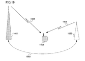
- FIG. 16 is a diagram illustrating an example of performing the CoMP method.
- FIG. 16 shows a case where a radio communication system using a heterogeneous network configuration is constructed by a macro base station 1601 having a wide coverage and an RRH (Remote Radio Head) 1602 having a coverage smaller than that of the macro base station.
- a case is considered in which the coverage of the macro base station 1601 includes a part or all of the coverage of the RRH 1602.
- a heterogeneous network configuration is constructed by the macro base station 1601 and the RRH 1602, and data communication with the terminal 1604 is performed through the downlink 1605 and the downlink 1606, respectively, in cooperation with each other.
- the macro base station 1601 is connected to the RRH 1602 via the line 1603, and can transmit and receive control signals and data signals to and from the RRH 1602.
- Each of the lines 1603 can be a wired line such as an optical fiber or a wireless line using relay technology.
- a part or all of the macro base station 1601 and the RRH 1602 use the same frequency (resource), so that the overall frequency utilization efficiency (transmission capacity) in the coverage area constructed by the macro base station 1601 is increased. It can be improved.
- the terminal 1604 When the terminal 1604 is located in the vicinity of the macro base station 1601 or the RRH 1602, the terminal 1604 can perform single cell communication with the macro base station 1601 or the RRH 1602. Furthermore, when the terminal 1604 is located near the edge (cell edge) of the coverage established by the RRH 1602, it is necessary to take measures against co-channel interference from the macro base station 1601. As multi-cell communication (cooperative communication) between the macro base station 1601 and the RRH 1602, a method of reducing or suppressing interference with the terminal 1604 in the cell edge region by using a CoMP scheme in which adjacent base stations cooperate with each other has been studied. For example, a method described in Non-Patent Document 2 has been studied as such a CoMP method.
- the transmission capacity that can be provided by one base station is improved, so that the number of terminals that can be accommodated also increases. Therefore, when the base station notifies the terminal of control information using conventional resources, there may be a shortage of resources to which control information is allocated. In this case, it becomes difficult for the base station to efficiently allocate data to the terminal, which is a factor that hinders improvement in transmission efficiency.
- the present invention has been made in view of the above problems, and an object of the present invention is to enable a base station to efficiently notify control information for a terminal in a wireless communication system in which the base station and the terminal communicate.
- a terminal a communication system, a communication method, and an integrated circuit.
- a base station uses a resource element configured using a frequency domain and a time domain, and a resource block pair configured using a predetermined number of resource elements.
- a base station that communicates with the terminal, and is different from the first control channel area to which the first control channel can be mapped, and is set from the base station to the terminal in units of resource block pairs,
- the control channel region includes a second control channel generating unit that generates a second control channel that can be mapped.
- a resource element group that is a set of predetermined resource elements in a resource block pair in the second control channel region is configured, and the second control channel is mapped to a plurality of resource element groups.
- a base station is the above-described base station, wherein the second control channel is mapped to a plurality of resource element groups in one resource block pair; One of the second methods mapped to a plurality of resource element groups in a plurality of resource block pairs is used.
- a base station is the base station described above, and includes information indicating either the first method or the second method used for the second control channel for the terminal. , Notify the terminal.
- the base station according to an aspect of the present invention is the above-described base station, and the second control channel is based on the terminal capability information or FGI notified from the terminal, and the second method and the second method.
- the terminal capability information or FGI indicates whether the terminal can function the first method and / or the second method.
- a base station is the base station described above, and a terminal-specific reference signal generation unit that generates a terminal-specific reference signal using the same antenna port as the second control channel;
- the control channel and the terminal-specific reference signal are further provided with a precoding unit that performs precoding processing in units of resource block pairs.
- a terminal uses a resource element configured using a frequency domain and a time domain, and a resource block pair configured using a predetermined number of resource elements.
- a terminal that communicates with the base station and is different from the first control channel area to which the first control channel can be mapped, and is set from the base station to the terminal in units of resource block pairs.
- a control channel processing unit for detecting a second control channel that can be mapped.
- a resource element group that is a set of predetermined resource elements in a resource block pair in the second control channel region is configured, and the second control channel is mapped to a plurality of resource element groups.
- a terminal according to an aspect of the present invention is the terminal described above, and the second control channel is mapped to a plurality of resource element groups in one resource block pair, One of the second methods mapped to a plurality of resource element groups in the resource block pair is used.
- a terminal is the above terminal, and information indicating either the first method or the second method used for the second control channel for the terminal is Notification from the station.
- a terminal according to an aspect of the present invention is the terminal described above, and the terminal capability information or FGI, which is information indicating whether the terminal can function the first method and / or the second method, Notify the station.
- FGI terminal capability information
- the terminal according to an aspect of the present invention is the terminal described above, and the control channel processing unit uses the terminal-specific reference signal that uses the same antenna port as the second control channel, and uses the second control channel. And the second control channel and the terminal-specific reference signal are assumed to be precoded in units of resource block pairs in each antenna port.
- a communication system includes a resource element configured using a frequency domain and a time domain, and a resource block pair configured using a predetermined number of resource elements. It is a communication system in which a base station and a terminal communicate with each other.
- the base station is a region different from the first control channel region to which the first control channel can be mapped, and can be mapped to the second control channel region set from the base station to the terminal in units of resource block pairs.
- a second control channel generation unit that generates a second control channel is provided.
- the terminal includes a control channel processing unit that detects the second control channel.
- a resource element group that is a set of predetermined resource elements in a resource block pair in the second control channel region is configured, and the second control channel is mapped to a plurality of resource element groups.
- a communication method includes a resource element configured using a frequency domain and a time domain, and a resource block pair configured using a predetermined number of resource elements.
- a communication method of a base station that communicates with a terminal, which is different from the first control channel region to which the first control channel can be mapped, and is set from the base station to the terminal in units of resource block pairs Generating a second control channel that can be mapped to the second control channel region.
- a resource element group that is a set of predetermined resource elements in a resource block pair in the second control channel region is configured, and the second control channel is mapped to a plurality of resource element groups.
- a communication method includes a resource element configured using a frequency domain and a time domain, and a resource block pair configured using a predetermined number of resource elements.
- the second control that is different from the first control channel region to which the first control channel can be mapped, and that is set from the base station to the terminal in units of resource block pairs and can be mapped to the second control channel region Detecting a channel.
- a resource element group that is a set of predetermined resource elements in a resource block pair in the second control channel region is configured, and the second control channel is mapped to a plurality of resource element groups.
- An integrated circuit includes a resource element configured using a frequency domain and a time domain, and a resource block pair configured using a predetermined number of resource elements. And an integrated circuit that functions in a base station that communicates with the terminal, and is an area different from the first control channel area to which the first control channel can be mapped. It has a function of generating a second control channel that can be mapped to the set second control channel region.
- a resource element group that is a set of predetermined resource elements in a resource block pair in the second control channel region is configured, and the second control channel is mapped to a plurality of resource element groups.
- An integrated circuit includes a resource element configured using a frequency domain and a time domain, and a resource block pair configured using a predetermined number of resource elements. And an integrated circuit that functions in a terminal that communicates with the base station, and is an area different from the first control channel area to which the first control channel can be mapped, and from the base station to the terminal in units of resource block pairs. It has a function of detecting a second control channel that can be mapped to the set second control channel region.
- a resource element group that is a set of predetermined resource elements in a resource block pair in the second control channel region is configured, and the second control channel is mapped to a plurality of resource element groups.
- the base station in a wireless communication system in which a base station and a terminal communicate, can efficiently notify control information for the terminal.
- the communication system includes a base station (transmitting device, cell, transmission point, transmitting antenna group, transmitting antenna port group, component carrier, eNodeB) and terminal (terminal device, mobile terminal, receiving point, receiving terminal). , Receiving device, receiving antenna group, receiving antenna port group, UE).
- the base station 100 transmits control information and information data through the downlink in order to perform data communication with the terminal 200.
- control information is subjected to error detection coding processing and the like, and is mapped to the control channel.
- the control channel (PDCCH; Physical Downlink Control Channel) is subjected to error correction coding processing and modulation processing, and is different from the first control channel (first physical control channel) region or the first control channel region. Transmission / reception is performed via two control channel (second physical control channel) regions.
- the physical control channel referred to here is a kind of physical channel and is a control channel defined on a physical frame.
- the first control channel is a physical control channel that uses the same transmission port (antenna port) as the cell-specific reference signal.
- the second control channel is a physical control channel that uses the same transmission port as the terminal-specific reference signal.
- the terminal 200 demodulates the first control channel using the cell-specific reference signal, and demodulates the second control channel using the terminal-specific reference signal.
- the cell-specific reference signal is a reference signal common to all terminals in the cell, and is a reference signal that can be used by any terminal because it is inserted into almost all resources. Therefore, any terminal can demodulate the first control channel.
- the terminal-specific reference signal is a reference signal inserted only in the allocated resource, and can perform adaptively a precoding process and a beamforming process like data. Therefore, adaptive precoding and beamforming gain can be obtained in the second control channel.
- the control channel (first control channel) mapped to the first control channel region is a physical control channel on an OFDM symbol (symbol) located at the front of the physical subframe. , And can be arranged over the entire system bandwidth (component carrier (CC)) on these OFDM symbols.
- the control channel (second control channel) mapped to the second control channel region is a physical control channel on the OFDM symbol located behind the first control channel of the physical subframe, and these It may be arranged in a part of the system bandwidth on the OFDM symbol. Since the first control channel is arranged on the OFDM symbol dedicated to the control channel located in the front part of the physical subframe, it can be received and demodulated before the rear OFDM symbol for the physical data channel.
- a terminal that monitors only the OFDM symbol dedicated to the control channel can also be received. Moreover, since it can be spread and arranged throughout the CC, inter-cell interference can be randomized.
- the first control channel region is a region that is set unique to the base station 100 and is a region that is common to all terminals connected to the base station 100.
- the second control channel is arranged on the rear OFDM symbol for the shared channel (physical data channel) normally received by the communicating terminal. Also, by frequency division multiplexing, the second control channels or the second control channel and the physical data channel can be orthogonally multiplexed (multiplexing without interference).
- the second control channel region is a region set for each terminal 200 and is set for each terminal connected to the base station 100.
- the base station 100 can set the second control channel region to be shared by a plurality of terminals. Further, the first control channel region and the second control channel region are arranged in the same physical subframe.
- the OFDM symbol is a unit in the time direction for mapping bits of each channel.
- the first control channel is a cell-specific physical control channel, which is a physical channel that can be acquired (detected) by both idle and connected terminals.
- the second control channel is a terminal-specific physical control channel, and is a physical channel that can be acquired only by a connected terminal.
- the idle state refers to a state in which the base station does not accumulate RRC (Radio Resource Control) information (RRC_IDLE state), a state in which the mobile station is performing intermittent reception (DRX), etc. This is a state where no operation is performed.
- RRC Radio Resource Control
- the connected state is a state in which data can be immediately transmitted / received, such as a state in which the terminal holds network information (RRC_CONNECTED state) and a state in which the mobile station is not performing intermittent reception (DRX).
- the first control channel is a channel that can be received by the terminal without depending on terminal-specific RRC signaling.
- the second control channel is a channel configured by terminal-specific RRC signaling, and is a channel that can be received by the terminal by terminal-specific RRC signaling.
- the first control channel is a channel that can be received by any terminal by setting limited in advance
- the second control channel is a channel in which the terminal-specific setting can be easily changed.
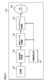
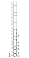
- FIG. 1 is a schematic block diagram showing the configuration of the base station 100 according to the first embodiment of the present invention.
- the base station 100 includes an upper layer 101, a data channel generation unit 102, a second control channel generation unit 103, a terminal-specific reference signal multiplexing unit 104, a precoding unit 105, a first control channel generation unit 106, A cell-specific reference signal multiplexing unit 107, a transmission signal generation unit 108, and a transmission unit 109 are provided.
- the upper layer 101 generates information data (transport block, codeword) for the terminal 200 and outputs it to the data channel generation unit 102.
- the information data can be a unit for performing error correction coding processing.
- the information data may be a unit for performing retransmission control such as HARQ (Hybrid Automatic Repeat reQuest).
- the base station 100 can transmit a plurality of information data to the terminal 200.
- the data channel generation unit (data channel region allocation unit, data channel mapping unit) 102 performs adaptive control on the information data output from the upper layer 101 and generates a data channel for the terminal 200.
- the adaptive control in the data channel generation unit 102 is to use an encoding process for performing error correction encoding, a scramble process for applying a scramble code unique to the terminal 200, a multi-level modulation scheme, and the like. Modulation processing, layer mapping processing for spatial multiplexing such as MIMO, and the like are performed.
- the layer mapping process in the data channel generation unit 102 maps to one or more layers (streams) based on the number of ranks set for the terminal 200.
- the second control channel generation unit (second control channel region allocation unit, second control channel mapping unit, terminal-specific control channel generation unit) 103 is configured so that the base station 100 uses the second control channel region (terminal-specific control channel).
- a control channel to be transmitted via the second control channel region is generated.
- the control channel transmitted via the second control channel region can be transmitted with the rank number fixed to 1, and can be mapped to one or more layers in the same manner as the data channel.
- the data channel generation unit 102 and the second control channel generation unit 103 are also referred to as a shared channel generation unit.
- the control channel transmitted via the second control channel region is also referred to as a second control channel.
- the data channel or the second control channel is also called a shared channel (shared channel).
- the second control channel is also referred to as E-PDCCH (Enhanced PDCCH) or terminal-specific control channel.
- the terminal-specific reference signal multiplexing unit (terminal-specific reference signal generation unit) 104 is a terminal-specific reference signal specific to the terminal 200 (data channel demodulation reference signal, second control channel demodulation reference signal, shared channel demodulation reference signal) , A terminal-specific control channel demodulation reference signal, DM-RS (Demodulation Reference Signal), DRS (Dedicated Reference Signal), Precoded RS, and UE-specific RS, and multiplex the terminal-specific reference signal on the shared channel.
- the terminal-specific reference signal is set based on the number of ranks of the shared channel to be multiplexed and multiplexed in each layer.
- the terminal-specific reference signal is preferably orthogonal and / or quasi-orthogonal between layers. Note that the terminal-specific reference signal multiplexing unit 104 may generate a terminal-specific reference signal and multiplex it in the transmission signal generation unit 108 described later.
- the precoding unit 105 performs precoding processing specific to the terminal 200 on the shared channel and the terminal specific reference signal output from the terminal specific reference signal multiplexing unit 104.
- precoding processing is performed so that terminal 200 can efficiently receive (for example, reception power is maximized, interference from adjacent cells is reduced, or interference with adjacent cells is reduced).
- processing by a predetermined precoding matrix CDD (Cyclic Delay Diversity), Transmit Diversity (SFBC (Spatial Frequency Block Code), STBC (Spatial Time Block Code), TSTDchSdDS Transmission Diversity) can be used, but is not limited thereto.
- the base station 100 feeds back a plurality of types of PMI (Precoding Matrix Indicator), which is feedback information related to the precoding process, from the terminal 200, the base station 100 sends the plurality of PMIs to the terminal 200.
- Precoding processing can be performed based on the result of computation by multiplication or the like.
- the terminal-specific reference signal is a signal known to the base station 100 and the terminal 200. Further, the precoding process unique to the terminal 200 is performed by the precoding unit 105 on the shared channel and the terminal-specific reference signal. Therefore, when the terminal 200 demodulates the shared channel, the terminal-specific reference signal is used so that the channel condition in the downlink between the base station 100 and the terminal 200 and the precoding weight equalization channel by the precoding unit 105 can be obtained. Can be estimated. That is, base station 100 does not need to notify terminal 200 of the precoding weight by precoding section 105, and can demodulate the precoded signal.
- control channel transmitted via the second control channel region is demodulated by the terminal-specific reference signal
- the control channel is subjected to precoding processing in the base station 100 in the same manner as the data channel.
- the transmission path condition is estimated by the terminal-specific reference signal in the terminal 200 as in the data channel, and demodulation processing is performed.
- the first control channel generation unit (first control channel region allocation unit, first control channel mapping unit, cell specific control channel generation unit) 106 is configured so that the base station 100 can control the first control channel region (cell specific control channel).
- first control channel region cell specific control channel
- the first control channel generation unit 106 is configured so that the base station 100 can control the first control channel region (cell specific control channel).
- a control channel to be transmitted via the first control channel region is generated.
- the control channel transmitted through the first control channel region is also referred to as a first control channel.
- the first control channel is also referred to as a cell-specific control channel.
- a cell-specific reference signal multiplexing unit (cell-specific reference signal generation unit) 107 is a cell known by the base station 100 and the terminal 200 in order to measure a downlink transmission path condition between the base station 100 and the terminal 200. Generate unique reference signals (reference signal for transmission path condition measurement, CRS (Common RS), Cell-specific RS, Non-precoded RS, cell-specific control channel demodulation reference signal, first control channel demodulation reference signal) . The generated cell-specific reference signal is multiplexed with the signal output by the first control channel generation unit 106. Note that the cell-specific reference signal multiplexing unit 107 may generate a cell-specific reference signal and multiplex it in the transmission signal generation unit 108 described later.
- CRS Common RS
- Cell-specific RS Cell-specific RS
- Non-precoded RS cell-specific control channel demodulation reference signal
- first control channel demodulation reference signal first control channel demodulation reference signal
- any signal can be used as the cell-specific reference signal as long as both the base station 100 and the terminal 200 are known signals.
- a random number or a pseudo noise sequence based on parameters assigned in advance such as a number (cell ID) unique to the base station 100 can be used.
- a method of orthogonalizing between antenna ports a method in which resource elements for mapping cell-specific reference signals are mutually null (zero) between antenna ports, a method of code division multiplexing using a pseudo noise sequence, or a combination thereof The method etc. can be used.
- the cell-specific reference signal may not be multiplexed in all subframes, and may be multiplexed only in some subframes.
- the cell-specific reference signal is a reference signal that is multiplexed after the precoding process by the precoding unit 105. Therefore, terminal 200 can measure the downlink transmission path status between base station 100 and terminal 200 using the cell-specific reference signal, and is a signal that has not been subjected to precoding processing by precoding section 105. Can be demodulated. For example, the first control channel can be demodulated by the cell-specific reference signal.
- the transmission signal generation unit (channel mapping unit) 108 performs a mapping process on the signal output from the cell-specific reference signal multiplexing unit 107 to the resource element of each antenna port. Specifically, the transmission signal generation unit 108 maps the data channel to the data channel region of the shared channel (PDSCH; Physical Downlink Shared Channel) region, and the second control channel to the second control channel region of the shared channel region. To map. Further, the transmission signal generation unit 108 maps the first control channel to a first control channel region different from the second control channel region.
- the base station 100 can map control channels addressed to a plurality of terminals in the first control channel region and / or the second control channel region.
- the transmission signal generation unit 108 performs switching based on the parameters of the base station and / or the terminal and / or the control channel To process. Details will be described later.
- the first control channel and the second control channel are a control channel to be transmitted via different resources and / or a control channel to be demodulated using different reference signals and / or the terminal 200, respectively.
- This is a control channel that can be transmitted according to different RRC states.
- Each control channel can map control information of any format.
- a format of control information that can be mapped can be defined for each control channel. For example, control information of all formats can be mapped to the first control channel, and control information of some formats can be mapped to the second control channel. For example, control information of all formats can be mapped to the first control channel, and control information of a format including data channel allocation information using a terminal-specific reference signal is mapped to the second control channel. can do.
- the format of the control channel is specified in advance.
- the control channel can be defined according to the purpose of the base station 100 notifying the terminal 200.
- the control information mapped to the control channel includes downlink data channel allocation information for terminal 200, uplink data channel (PUSCH; Physical Uplink Shared Channel) and control channel (PUCCH; Physical) for terminal 200. (Uplink Control Channel) allocation information, information for controlling transmission power to the terminal 200, and the like. Therefore, for example, when the base station 100 transmits downlink information data to the terminal 200, the control channel to which control information including downlink data channel allocation information for the terminal 200 is mapped, and its control A data channel to which information data assigned based on the information is mapped is transmitted.
- the base station 100 when allocating an uplink data channel to the terminal 200, transmits a control channel to which control information including uplink data channel allocation information for the terminal 200 is mapped.
- the base station 100 can transmit a plurality of different control channels or the same control channel to the same terminal 200 in the same subframe in different formats or the same format. Note that, when the base station 100 transmits downlink information data to the terminal 200, what is a subframe for transmitting a control channel to which control information including downlink data channel allocation information for the terminal 200 is mapped? It is also possible to transmit downlink data channels in different subframes.
- the first control channel region is a region unique to the base station 100, it is also referred to as a cell-specific control channel region.
- the second control channel region is a region specific to terminal 200 set from base station 100 through RRC signaling, and is also referred to as a terminal-specific control channel region.
- the second control channel region is set in units of regions in which two resource blocks composed of a predetermined frequency direction region and a predetermined time direction region are continuously arranged in the time direction.
- the transmission unit 109 performs inverse fast Fourier transform (IFFT: Inverse Fast Fourier Transform), addition of a guard interval, conversion processing to a radio frequency, etc. Transmit from the transmitting antenna.
- IFFT Inverse Fast Fourier Transform
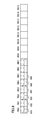
- FIG. 2 is a schematic block diagram showing the configuration of the terminal 200 according to the first embodiment of the present invention.
- terminal 200 includes reception section 201, reception signal processing section 202, propagation path estimation section 203, control channel processing section 204, data channel processing section 205, and higher layer 206.
- the receiving unit 201 receives a signal transmitted from the base station 100 by one or a plurality of receiving antennas (the number of receiving antenna ports), performs a conversion process from a radio frequency to a baseband signal, and an added guard. Time frequency conversion processing such as interval removal and Fast Fourier Transform (FFT) is performed.
- FFT Fast Fourier Transform
- the received signal processing unit 202 demaps (separates) the signal mapped by the base station 100. Specifically, the received signal processing unit 202 demaps the first control channel and / or the second control channel and / or the data channel, and outputs the demapped signal to the control channel processing unit 204. Also, received signal processing section 202 demaps the multiplexed cell-specific reference signal and / or terminal-specific reference signal and outputs the result to propagation path estimation section 203.
- the propagation path estimation unit 203 performs propagation path estimation for the resources of the first control channel and / or the second control channel and / or the data channel based on the cell-specific reference signal and / or the terminal-specific reference signal.
- the propagation path estimation unit 203 outputs the estimation result of the propagation path estimation to the control channel processing unit 204 and the data channel processing unit 205.
- the propagation path estimation unit 203 determines the amplitude in each resource element for each reception antenna port of each layer (rank, spatial multiplexing). And phase fluctuation (frequency response, transfer function) are estimated (propagation path estimation), and a propagation path estimation value is obtained. Further, the propagation path estimation unit 203 estimates amplitude and phase fluctuations in each resource element for each reception antenna port of each transmission antenna port based on the cell-specific reference signal multiplexed on the first control channel. Then, a propagation path estimation value is obtained.
- the control channel processing unit 204 searches for a control channel addressed to the terminal 200 mapped to the first control channel region and / or the second control channel region.
- the control channel processing unit 204 sets a first control channel region and / or a second control channel region as a control channel region for searching for a control channel.
- the setting of the second control channel region is performed through upper layer control information (for example, RRC (Radio Resource Control) signaling) that the base station 100 notifies the terminal 200 of.
- RRC Radio Resource Control
- the setting of the second control channel region is control information for setting the second control channel as the terminal-specific setting information of the second control channel, and is setting information specific to the terminal 200. Details of the setting of the second control channel region will be described later.
- control channel processing unit 204 performs switching based on the parameters of the base station and / or the terminal and / or the control channel. To process. Details will be described later.
- the control channel processing unit 204 is mapped to the second control channel region A control channel addressed to terminal 200 is searched.
- the control channel processing unit 204 may also search for a partial region in the first control channel region.
- the control channel processing unit 204 may also search for a cell-specific search region in the first control channel region.
- the control channel processing unit 204 is mapped to the first control channel region. A control channel addressed to terminal 200 is searched.
- the control channel processing unit 204 uses a terminal-specific reference signal to demodulate a possible control channel.
- the control channel processing unit 204 uses a cell-specific reference signal to demodulate a possible control channel.
- control channel processing unit 204 displays all or part of control channel candidates obtained based on the type of control information, the location of the mapped resource, the size of the mapped resource, the aggregation level, and the like. Then, a demodulation and a decoding process are performed, and a sequential search is performed.
- the control channel processing unit 204 uses an error detection code (for example, a CRC (Cyclic Redundancy Check) code) added to the control information as a method for determining whether or not the control information is addressed to the terminal 200. Such a search method is also called blind decoding.
- error detection code for example, a CRC (Cyclic Redundancy Check) code
- control channel processing unit 204 detects a control channel addressed to the terminal 200
- control channel processing unit 204 identifies control information mapped to the detected control channel, and is shared by the entire terminal 200 (including higher layers), and is downlinked. It is used for various controls in terminal 200 such as data channel reception processing, uplink data channel and control channel transmission processing, and uplink transmission power control.
- control channel processing unit 204 When control information including downlink data channel allocation information is mapped to the detected control channel, the control channel processing unit 204 sends the data channel demapped by the received signal processing unit 202 to the data channel processing unit 205. Output.
- the data channel processing unit 205 performs channel compensation processing (filter processing), layer demapping using the channel estimation result input from the channel estimation unit 203 on the data channel input from the control channel processing unit 204. Processing, demodulation processing, descrambling processing, error correction decoding processing, etc. are performed and output to the upper layer 206. Note that the resource element to which the terminal-specific reference signal is not mapped is subjected to channel estimation by performing interpolation or averaging in the frequency direction and the time direction based on the resource element to which the terminal-specific reference signal is mapped. In the propagation path compensation processing, propagation path compensation is performed on the input data channel using the estimated propagation path estimation value, and a signal for each layer based on the information data is detected (restored).
- ZF Zero Forcing
- MMSE Minimum Mean Square Error normization
- turbo equalization turbo equalization
- interference removal or the like
- the layer demapping process the demapping process is performed on the signal of each layer to the respective information data. The subsequent processing is performed for each information data.
- demodulation demodulation is performed based on the modulation method used.
- descrambling process the descrambling process is performed based on the used scramble code.
- an error correction decoding process is performed based on the applied encoding method.
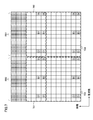
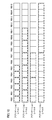
- FIG. 3 is a diagram illustrating an example of one resource block pair mapped by the base station 100.
- One resource block is composed of a predetermined frequency direction region and a predetermined time direction region, and one resource block pair is continuously arranged in the time direction.
- FIG. 3 shows two resource blocks (RB), and one resource block is composed of 12 subcarriers in the frequency direction and 7 OFDM symbols in the time direction. Each subcarrier in one OFDM symbol is called a resource element.
- Resource block pairs are arranged in the frequency direction, and the number of resource block pairs can be set for each base station. For example, the number of resource block pairs can be set to 6 to 110.
- the width in the frequency direction at that time is called a system bandwidth.
- the time direction of the resource block pair is called a subframe. Of each subframe, the seven OFDM symbols before and after in the time direction are also called slots.
- a resource block pair is also simply referred to as a resource block.
- R0 to R1 indicate cell-specific reference signals of the antenna ports 0 to 1, respectively.
- the cell-specific reference signal shown in FIG. 3 is a case of two antenna ports, but the number thereof can be changed.
- the cell-specific reference signal for one antenna port or four antenna ports is mapped. be able to.
- the channel state measurement reference signal can be set as a cell-specific reference signal different from the cell-specific reference signals of antenna ports 0 to 1 shown in FIG.
- the reference signal for transmission path condition measurement can be set as reference signals corresponding to eight antenna ports from antenna ports 15 to 22, for example. Further, the transmission path condition measurement reference signal can be mapped to some subframes, for example, can be mapped for each of a plurality of subframes.
- the base station 100 sets a transmission path condition measurement reference signal as terminal-specific control information for the terminal 200 through RRC signaling. Based on the setting from base station 100, terminal 200 generates feedback information using the cell-specific reference signals of antenna ports 0 to 1 and / or the transmission path condition measurement reference signal.
- D1 to D2 indicate terminal-specific reference signals of CDM (Code Division Multiplexing) group 1 to CDM group 2, respectively.
- the terminal-specific reference signals of CDM group 1 and CDM group 2 are code division multiplexed by orthogonal codes such as Walsh codes, respectively, within the CDM group.
- the terminal-specific reference signals of CDM group 1 and CDM group 2 are frequency division multiplexed (FDM) between the CDM groups.
- the terminal-specific reference signal can be mapped to a maximum of 8 ranks using 8 antenna ports (antenna ports 7 to 14) according to the control channel or data channel mapped to the resource block pair.
- the terminal-specific reference signal can change the CDM spreading code length and the number of mapped resource elements in accordance with the number of ranks to be mapped.
- the terminal-specific reference signal in the case where the rank number is 1 to 2 is configured by antenna code 7 to 8 with a spread code length of 2 chips and mapped to CDM group 1.
- the terminal-specific reference signal in the case where the number of ranks is 3 to 4 is configured by antenna chips 9 to 10 in addition to antenna ports 7 to 8 and having a spreading code length of 2 chips, and is further mapped to CDM group 2.
- the terminal-specific reference signals in the case where the number of ranks is 5 to 8 are configured as 4-port spreading code lengths as antenna ports 7 to 14 and are mapped to CDM group 1 and CDM group 2.
- the orthogonal code of each antenna port is further superimposed by a scramble code.
- This scramble code is generated based on control information notified from the base station 100.
- the scramble code is generated from a pseudo-noise sequence generated based on the cell ID and scramble ID notified from the base station 100.
- the scramble ID is a value indicating 0 or 1.
- the scramble ID and antenna port used can be jointly coded, and information indicating them can be indexed.
- a region composed of the first to third OFDM symbols at the head is set as a region where the first control channel is arranged (first control channel region). Further, the region where the first control channel is arranged is mapped to the front OFDM symbol in the subframe, and a predetermined number of OFDM symbols can be set for each subframe.
- the predetermined number of OFDM symbols in which the first control channel is arranged is broadcast (notified) as cell-specific control information through PCFICH (Physical Control Format Indicator Channel).
- the resource element filled in white indicates an area (shared channel area) where the shared channel is arranged.
- the region where the shared channel is arranged is mapped to an OFDM symbol different from the OFDM symbol behind the OFDM symbol in the subframe, that is, the first control channel in the subframe.
- An OFDM symbol can be set. Note that all or a part of the region where the shared channel is arranged can be mapped to a fixed OFDM symbol regardless of the first control channel region in the subframe.
- the region where the second control channel is arranged (second control channel region) is the fourth to fourteenth OFDM symbol in the subframe regardless of the first control channel region in the subframe. You may make it map.
- the area where the shared channel is arranged can be set for each resource block pair.
- the number of resource blocks can be changed according to the frequency bandwidth (system bandwidth) used by the communication system.
- the frequency bandwidth system bandwidth
- 6 to 110 resource blocks can be used, and the unit is also called a component carrier.
- the base station can set a plurality of component carriers for the terminal by frequency aggregation.
- one component carrier is configured with 20 MHz for a terminal, and five component carriers are set continuously and / or discontinuously in the frequency direction, so that a total communication system can use.
- the bandwidth can be 100 MHz.
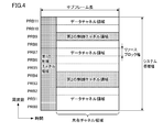
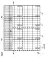
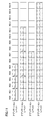
- FIG. 4 is a diagram illustrating an example of channels to which the base station 100 maps.
- FIG. 4 shows a case where a frequency band constituted by 12 physical resource block pairs (PRBs) is used as a system bandwidth.
- the PDCCH that is the first control channel is arranged in the first 1 to 3 OFDM symbols in the subframe.
- the frequency direction of the first control channel is arranged over the system bandwidth.
- the shared channel is arranged in an OFDM symbol other than the first control channel in the subframe.
- the PDCCH is composed of a plurality of control channel elements (CCE; Control Channel Element).
- CCE Control Channel Element
- the number of CCEs used in each downlink component carrier is a downlink cell-specific reference according to the downlink component carrier bandwidth, the number of OFDM symbols constituting the PDCCH, and the number of transmission antennas of the base station 100 used for communication. Depends on the number of transmit antenna ports of the signal.
- the CCE is composed of a plurality of downlink resource elements (resources defined by one OFDM symbol and one subcarrier).
- a number for identifying the CCE is assigned to the CCE used between the base station 100 and the terminal 200.
- the CCE numbering is performed based on a predetermined rule.
- CCE_t indicates the CCE of CCE number t.
- the PDCCH is configured by a set of a plurality of CCEs (CCE aggregation).
- the number of CCEs constituting this set is referred to as a “CCE aggregation level” (CCE aggregation level).
- the CCE aggregation level constituting the PDCCH is set in the base station according to the coding rate set in the PDCCH and the number of bits of DCI included in the PDCCH. Note that combinations of CCE aggregation levels that may be used for terminals are determined in advance.
- a set of n CCEs is referred to as “CCE set level n”.
- One resource element group is composed of four downlink resource elements adjacent in the frequency domain. Furthermore, one CCE is composed of nine different resource element groups distributed in the frequency domain and the time domain. Specifically, with respect to the entire downlink component carrier, interleaving is performed on a resource element group basis for all numbered resource element groups using a block interleaver, and nine consecutive numbers after interleaving are performed. One CCE is configured by the resource element group.
- a region SS (Search Space) for searching for PDCCH is set.
- the SS is composed of a plurality of CCEs.
- the SS is composed of a plurality of CCEs having consecutive numbers from the smallest CCE, and the number of CCEs having consecutive numbers is predetermined.
- Each CCE aggregation level SS is composed of an aggregation of a plurality of PDCCH candidates.
- SSs are classified into CSS (Cell-specific SS) in which the number is common in the cell from the smallest CCE and USS (UE-specific SS) in which the number is unique to the terminal from the smallest CCE.
- CSS is assigned a PDCCH to which control information read by a plurality of terminals such as system information or information related to paging is assigned, or a downlink / uplink grant indicating an instruction of fallback or random access to a lower transmission method.
- PDCCH can be arranged.
- the base station transmits the PDCCH using one or more CCEs in the SS set in the terminal 200.
- Terminal 200 decodes the received signal using one or more CCEs in the SS and performs processing for detecting the PDCCH addressed to itself (referred to as blind decoding).
- the terminal 200 sets a different SS for each CCE aggregation level.
- terminal 200 performs blind decoding using a predetermined combination of CCEs in different SSs for each CCE aggregation level. In other words, terminal 200 performs blind decoding on each PDCCH candidate in a different SS for each CCE aggregation level. This series of processing in terminal 200 is called PDCCH monitoring.
- the second control channel (E-PDCCH, PDCCH on PDSCH, Enhanced PDCCH) mapped to the second control channel region is arranged in an OFDM symbol other than the first control channel region.
- the shared channel region is arranged in different resource blocks. Further, the resource block in which the shared channel region can be arranged is set for each terminal. Also, the same method as that for the shared channel can be used for the start position of the OFDM symbol in which the second control channel is arranged. That is, the base station 100 can be realized by setting some resources in the first control channel region as PCFICH and mapping information indicating the number of OFDM symbols in the first control channel region.
- the start position of the OFDM symbol in which the second control channel region is arranged is defined in advance, and may be, for example, the first fourth OFDM symbol in the subframe. At that time, if the number of OFDM symbols in the first control channel region is 2 or less, the second to third OFDM symbols in the resource block pair in which the second control channel region is arranged do not map signals. Null. Note that other control channels and data channels can be further mapped to resources set as null.
- the start position of the OFDM symbol that sets the second control channel region can be set through higher layer control information.
- the subframes shown in FIG. 4 are time-multiplexed, and the second control channel region can be set for each subframe.
- the base station 100 When the base station 100 notifies the terminal 200 of the control channel through the second control channel region, the base station 100 sets the second control channel monitoring to the terminal 200, and the second control channel region The control channel for terminal 200 is mapped to. Further, when the base station 100 notifies the terminal 200 of the control channel through the first control channel region, the base station 100 does not set the monitoring of the second control channel for the terminal 200, and does not set the first control channel region. The control channel for terminal 200 is mapped to the control channel region.
- the terminal 200 when monitoring of the second control channel is set by the base station 100, the terminal 200 performs blind decoding on the control channel addressed to the terminal 200 in the second control channel region. In addition, when the monitoring of the second control channel is not set by the base station 100, the terminal 200 does not blind-decode the control channel addressed to the terminal 200 in the second control channel.
- control channel mapped to the second control channel region will be described.
- the control channel mapped to the second control channel region is processed for each control information for one terminal, and scramble processing, modulation processing, layer mapping processing, precoding processing, and the like are performed in the same manner as the data channel.
- control channel mapped to the second control channel region is subjected to precoding processing specific to terminal 200 together with the terminal specific reference signal.
- the precoding process is preferably performed with precoding weights suitable for the terminal 200.
- control channel mapped to the second control channel region is mapped including different control information in the front slot (first slot) and the rear slot (second slot) in the subframe.
- a control channel including allocation information (downlink allocation information) in a downlink shared channel that the base station 100 transmits to the terminal 200 is mapped to the forward slot in the subframe.
- a control channel including allocation information (uplink allocation information) in the uplink shared channel transmitted from terminal 200 to base station 100 is mapped to the rear slot in the subframe.
- a control channel including uplink allocation information for the base station 100 for the terminal 200 is mapped to the forward slot in the subframe
- downlink allocation information for the base station 100 to the base station 100 is mapped to the rear slot in the subframe. May be mapped.
- data channels for terminal 200 and / or other terminals may be mapped to the front and / or rear slots in the second control channel region.
- control channels for terminal 200 and / or other terminals may be mapped to the front and / or rear slots in the second control channel region.
- the terminal-specific reference signal similar to the data channel is multiplexed by the base station 100 on the control channel mapped to the second control channel region.
- Terminal 200 demodulates the control channel mapped to the second control channel region using the multiplexed terminal-specific reference signal. Also, some or all of the terminal-specific reference signals of the antenna ports 7 to 14 are used. At that time, the control channel mapped to the second control channel region can be MIMO-transmitted using a plurality of antenna ports.
- the terminal-specific reference signal in the second control channel region is transmitted using a predefined antenna port and scramble code.
- the terminal-specific reference signal in the second control channel region is generated using a predefined antenna port 7 and scramble ID.
- the terminal-specific reference signal in the second control channel region may be notified through RRC signaling, signaling by the first control channel, or signaling by the second control channel in the previous subframe, and It is generated using a scramble ID.
- RRC signaling signaling by the first control channel, or signaling by the second control channel in the previous subframe
- Either antenna port 7 or antenna port 8 is notified.
- the scramble ID used by the terminal-specific reference signal in the second control channel region through RRC signaling, signaling by the first control channel, or signaling by the second control channel in the previous subframe, Any value from 0 to 3 is notified.
- a cell-specific reference signal may be used in addition to the terminal-specific reference signal.
- the second control channel setting method (second control channel region setting method, second control channel monitoring setting method) for the base station 100 to the terminal 200
- the second control channel region And the setting of the transmission mode implicitly indicate the setting of monitoring of the second control channel.
- the base station 100 sets the second control channel by notifying the terminal 200 of the terminal-specific setting information (RadioResourceConfigDedicated) for the radio resource through the higher layer control information.
- the terminal-specific setting information for radio resources is control information used for setting / changing / releasing resource blocks, terminal-specific settings for physical channels, and the like.
- the base station 100 notifies the terminal 200 of terminal-specific setting information for the radio resource.
- Terminal 200 performs terminal-specific settings for radio resources based on terminal-specific setting information for radio resources from base station 100, and notifies base station 100 of completion of setting of terminal-specific setting information for radio resources.
- the terminal-specific setting information for the radio resource includes terminal-specific setting information (PhysicalConfigDedicated) for the physical channel.
- the terminal-specific setting information for the physical channel is control information that defines terminal-specific settings for the physical channel.
- the terminal-specific setting information for the physical channel includes transmission path status report setting information (CQI-ReportConfig), terminal information for antenna information (AntennaInfoDedicated), and terminal-specific setting information for the second control channel (EPDCCH-ConfigDedicated). Consists of.
- the setting information of the transmission path status report is used to define setting information for reporting the transmission path status in the downlink.
- the terminal-specific setting information in the antenna information is used to define terminal-specific antenna information in the base station 100.
- the terminal-specific setting information for the second control channel is used to define terminal-specific setting information for the second control channel. Further, since the terminal-specific setting information of the second control channel is notified and set as control information specific to terminal 200, the second control channel area to be set is set as an area specific to terminal 200.
- the setting information of the transmission path status report includes aperiodic transmission path status report setting information (CQI-ReportModeAperiodic) and periodic transmission path status report setting information (CQI-ReportPeriodic).
- the setting information of the non-periodic transmission path status report is setting information for aperiodically reporting the transmission path status in the downlink through the uplink shared channel (PUSCH) (Physical Uplink Shared Channel).
- the setting information of the periodic transmission path status report is setting information for periodically reporting the transmission path status in the downlink through the uplink control channel (PUCCH; Physical Uplink Control Channel).
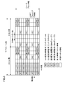
- the terminal-specific setting information of the antenna information includes a transmission mode (transmission Mode).
- the transmission mode is information indicating a transmission method in which the base station 100 communicates with the terminal 200.
- the transmission mode is defined in advance as transmission modes 1 to 10.
- Transmission mode 1 is a transmission mode that uses a single antenna port transmission scheme that uses antenna port 0.
- Transmission mode 2 is a transmission mode using a transmission diversity method.
- Transmission mode 3 is a transmission mode that uses a cyclic delay diversity scheme.
- Transmission mode 4 is a transmission mode that uses a closed-loop spatial multiplexing scheme.
- Transmission mode 5 is a transmission mode that uses a multi-user MIMO scheme.
- Transmission mode 6 is a transmission mode that uses a closed-loop spatial multiplexing scheme that uses a single antenna port.
- the transmission mode 7 is a transmission mode using a single antenna port transmission method using the antenna port 5.
- Transmission mode 8 is a transmission mode that uses a closed-loop spatial multiplexing scheme that uses antenna ports 7 to 8.
- Transmission mode 9 is a transmission mode that uses a closed-loop spatial multiplexing scheme that uses antenna ports 7 to 14. Transmission modes 1 to 9 are also referred to as a first transmission mode.
- the transmission mode 10 is defined as a transmission mode different from the transmission modes 1 to 9.
- the transmission mode 10 can be a transmission mode using a CoMP scheme.
- the expansion due to the introduction of the CoMP method includes optimization of the transmission path status report and improvement of accuracy (for example, introduction of precoding information suitable for CoMP communication, phase difference information between base stations, etc.) and the like.
- the transmission mode 10 can be a transmission mode that uses a communication method that is an extension (advanced) of the multi-user MIMO method that can be realized by the communication methods shown in the transmission modes 1 to 9.
- the extension of the multi-user MIMO scheme is optimized for transmission path status reports and improved accuracy (for example, introduction of CQI (Channel Quality Indicator) information suitable for multi-user MIMO communication) and multiplexed on the same resource. Including improvement of orthogonality between terminals.
- CQI Channel Quality Indicator
- the transmission mode 10 can be a transmission mode that uses the CoMP method and / or the extended multi-user MIMO method in addition to all or part of the communication methods shown in the transmission modes 1 to 9.
- the transmission mode 10 can be a transmission mode that uses a CoMP scheme and / or an extended multi-user MIMO scheme in addition to the communication scheme shown in the transmission mode 9.
- the transmission mode 10 can be a transmission mode in which a plurality of transmission path condition measurement reference signals (CSI-RS; Channel State Information-RS) can be set.
- CSI-RS transmission path condition measurement reference signals
- the transmission mode 10 is also called a second transmission mode.
- the base station 100 does not notify the terminal set to the transmission mode 10 that can use a plurality of transmission schemes that one of the plurality of transmission schemes is used when transmitting the data channel. Can also communicate. That is, even if the terminal 200 is set to the transmission mode 10 that can use a plurality of transmission schemes, the terminal 200 can communicate without receiving any notification of using one of the plurality of transmission schemes when receiving a data channel. it can.
- the second transmission mode is a transmission mode in which the second control channel can be set. That is, when the base station 100 sets the terminal 200 to the first transmission mode, the base station 100 maps the control channel for the terminal 200 to the first control channel region. Further, when the base station 100 is set to the second transmission mode for the terminal 200, the base station 100 maps the control channel for the terminal 200 to the first control channel region or the second control channel region. On the other hand, when the base station 100 sets the first transmission mode, the terminal 200 performs blind decoding on the first control channel. Furthermore, when the base station 100 sets the second transmission mode, the terminal 200 performs blind decoding on either the first control channel or the second control channel.
- the terminal 200 when the terminal 200 is set to the second transmission mode, the terminal 200 sets a control channel for blind decoding based on whether or not the terminal-specific setting information of the second control channel is set by the base station 100. . That is, when the terminal 200 is set to the second transmission mode by the base station 100 and the terminal-specific setting information of the second control channel is set, the terminal 200 uses the first control channel and / or the second control channel. Blind decoding. Also, when the terminal 200 is set to the second transmission mode by the base station 100 and the terminal-specific setting information of the second control channel is not set, the terminal 200 performs blind decoding on the first control channel.
- the terminal-specific setting information of the second control channel includes subframe setting information (EPDCCH-SubframeConfig-r11) of the second control channel.
- the subframe setting information of the second control channel is used for defining subframe information for setting the second control channel.
- the second control channel subframe setting information includes a subframe setting pattern (subframeConfigPattern-r11) and second control channel setting information (epdcch-Config-r11).
- the subframe setting pattern is information indicating a subframe for setting the second control channel.
- the subframe setting pattern is n-bit bitmap format information. The information shown in each bit indicates whether or not the subframe is set as the second control channel. That is, the subframe setting pattern can set n subframes as a cycle. At that time, a predetermined subframe to which a synchronization signal, a broadcast channel, and the like are mapped can be excluded. Specifically, the remainder obtained by dividing the subframe number defined for each subframe by n corresponds to each bit of the subframe setting pattern. For example, n is defined in advance as a value such as 8 or 40.
- the subframe When the information for a subframe having a subframe setting pattern is “1”, the subframe is set as the second control channel. When information on a subframe having a subframe setting pattern is “0”, the subframe is not set as the second control channel.
- a predetermined subframe to which a synchronization signal for the terminal 200 to synchronize with the base station 100, a broadcast channel for broadcasting the control information of the base station 100, and the like is mapped is not set as a second control channel in advance. can do.
- the subframe pattern set as the second control channel is indexed in advance, and information indicating the index is defined as the subframe setting pattern.
- the setting information of the second control channel includes a resource allocation type (resourceAllocationType-r11) and resource allocation information (resourceBlockAssignment-r11).
- the resource allocation type is information indicating a format (type) of information for designating a resource block to be set as the second control channel region in the subframe.
- the resource allocation information is information for designating a resource block to be set as the second control channel, and is defined based on the resource allocation type format.
- the resource allocation type can specify multiple resource allocation information as types 0-2.
- the resource allocation information is control information for allocating to VRB (Virtual Resource Block).
- the resource allocation information is information in a bitmap format that can be allocated for each resource block group defined in units of a plurality of consecutive VRBs. Note that the number of VRBs in the resource block group can be defined according to the system bandwidth.
- the resource allocation type is type 1
- the resource allocation information is allocated for each VRB in the plurality of resource block group subsets in the resource block group subset in which each VRB in the resource block group is defined as one of the plurality of subsets.
- Bitmap format information that can be.
- the resource allocation information also includes information indicating the selected resource block group subset.
- the resource allocation information is information indicating the VRB that is the start of allocation and information indicating the number of VRBs to be allocated in consecutive VRBs.
- the number of VRBs is the same as the number of PRBs.
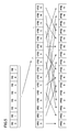
- VRB is defined in a plurality of types. These types define VRB to PRB mapping (PRB mapping).
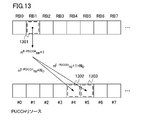
- PRB mapping In the Localized type, mapping is performed so that the VRB number (VRB position) and the PRB number (PRB number) are the same.
- the PRB numbers are assigned in order from the PRB having the lowest frequency.
- the VRB numbers are mapped by a predetermined method so that the VRB numbers are distributed (random) with respect to the PRB numbers.
- hopping can be further performed between slots, and the second slot of each VRB can be hopped to a different VRB. Whether or not to hop the second slot may be notified by RRC signaling or PDCCH signaling and switched, or may be defined in advance.
- RRC signaling or PDCCH signaling and switched or may be defined in advance.
- the PRB mapping is only the localized type.
- the PRB mapping is a localized type or a distributed type.
- the resource allocation type included in the setting information of the second control channel also includes control information (PRB mapping information) for PRB mapping.
- the resource allocation type can be control information indicating any of type 0, type 1, type 2 localized, and type 2 distributed.
- the base station 100 when setting the second control channel for the terminal 200, the base station 100 includes the terminal-specific setting information of the second control channel in the terminal-specific setting information for the radio resource by RRC signaling. To notify. Further, when the base station 100 changes the second control channel set for the terminal 200, the radio resource including the terminal-specific setting information of the second control channel whose parameter has been changed similarly by RRC signaling. Notify terminal-specific setting information for. Further, when releasing (releasing) the set second control channel, the base station 100 similarly notifies the terminal 200 by RRC signaling. For example, the terminal specific setting information for the radio resource not including the terminal specific setting information of the second control channel is notified. Also, control information for releasing the terminal-specific setting information of the second control channel may be notified.
- control channels for terminals set in transmission modes 1 to 10 are mapped in the first control channel area, and controls for terminals set in transmission mode 10 are mapped in the second control channel area.
- Channels can be mapped. That is, the base station 100 can notify the control channel through the first control channel region regardless of the transmission mode set for the terminal 200. Further, the base station 100 can notify the control channel through the second control channel region when the transmission mode 10 is set for the terminal 200. Therefore, the base station 100 can perform resource allocation scheduling in consideration of communication methods that are possible in the transmission mode 10.
- the base station 100 can perform a CoMP communication method, a multi-user MIMO communication method, or the like for the terminal 200, and therefore considers these communication methods. Resource allocation can be scheduled.
- the base station 100 can set the first control channel for all terminals, it is possible to maintain backward compatibility with terminals that cannot set the transmission mode 10.
- the notification of the control channel by the first control channel region can be realized without setting the second control channel, the overhead of control information in RRC signaling can be reduced.
- Base station 100 transmits one or more second control channels using one or more RBs. Further, the second control channel region is assigned for each RB pair.
- FIG. 5 is a diagram illustrating an example of mapping of the second control channel region.
- the example of FIG. 5 shows a case where the second control channel region using 8 RBs (RB0 to RB7) is mapped to the system bandwidth using 16 PRBs (PRB0 to PRB15).
- the second control channel region is mapped to a part or all of 16 VRBs (VRB0 to VRB15).
- the mapping for VRB is set by the resource allocation type (resourceAllocationType-r11) and the resource allocation information (resourceBlockAssignment-r11) included in the setting information of the second control channel notified through RRC signaling.
- the example shown in FIG. 5 shows a case where the resource allocation type is Type 2 Distributed. Also, in the resource allocation information, the starting VRB is VRB5, and the number of allocated VRBs is 8. At that time, the second control channel regions of RB0 to RB7 are mapped to VRB5 to VRB12. Since the PRB mapping information is of the distributed type, the VRB is mapped (interleaved) to the PRB so as to be distributed (randomly) by a predetermined method. In the example of FIG. 5, VRB5 to VRB12 are mapped to PRB6, PRB9, PRB14, PRB2, PRB7, PRB10, PRB15, and PRB3, respectively.
- a plurality of mapping methods of the second control channel to the second control channel region are defined.
- a mapping method of the second control channel to the second control channel region a method in which each second control channel is mapped in units of each slot (ie, RB) in the RB pair
- a method is defined in which each control channel is mapped in units of resources divided into a plurality of slots in the RB pair. That is, as a method for mapping the second control channel to the second control channel region, a method in which all or part of one second control channel is mapped to one RB, and a plurality of methods to one RB A method is defined in which all or part of the second control channel is mapped.
- each second control channel is mapped in units of each slot (ie, RB) in the RB pair is a method of mapping to resources of some resource blocks in the terminal-specific control channel region, or a terminal In other words, it is a method of mapping the terminal-specific control channel to all resources in each resource block, which are resources of some resource blocks in the specific control channel region.
- the method in which each second control channel is mapped in units of resources divided into a plurality of slots in the RB pair is a resource of a part of resource blocks in the terminal-specific control channel region, and the resource In other words, this is a method of mapping a terminal-specific control channel to some resources divided into a plurality of blocks.
- FIG. 6 is a diagram illustrating an example of mapping of the second control channel to the second control channel region using 16 RBs.
- FIG. 6 shows an example of mapping of the second control channel in the first slot.
- the second control channel is mapped to the second slot as well as the first slot and independently.
- each second control channel is mapped in units of each slot (that is, RB) in the RB pair.
- six second control channels are mapped to 16 RBs (RB0 to RB15).
- the second control channel 601 that uses one RB is mapped to RB0.
- the second control channel 602 that uses one RB is mapped to RB1.
- the second control channel 603 that uses one RB is mapped to RB2.
- a second control channel 604 that uses one RB is mapped to RB3.
- a second control channel 605 that uses two RBs is mapped to RB4 and RB5.
- a second control channel 606 using two RBs is mapped to RB6 and RB7. Note that a data channel can be mapped to an RB that is set as the second control channel region but is not mapped to the second control channel, that is, VRB / PRB corresponding to RB8 to RB15.
- FIG. 7 is a diagram showing details of mapping of the second control channel.
- FIG. 7 shows the RB pair of RB0 and RB1 shown in FIG.
- the first three OFDM symbols are the first control channel region.
- resource 701 is set in RB0
- resource 702 is set in RB1.
- resource 703 is set in RB0
- resource 704 is set in RB1.
- the second control channel 601 shown in FIG. 6 is mapped to the resource 701, and the second control channel 602 is mapped to the resource 702.
- Each second control channel can be defined in advance so that the terminal control signal is multiplexed and the second control channel is not mapped to the resource element to which the terminal specific reference signal is mapped. Further, when some signals such as a cell-specific reference signal, a transmission path condition measurement reference signal, and control information are mapped in the second control channel, the resource element to be mapped includes the second control channel. Can be defined in advance so as not to be mapped.
- the RB pair is obtained.
- the plurality of terminal-specific reference signals multiplexed in each slot can be averaged, interpolated, etc., and excellent estimation accuracy of the propagation path can be realized.
- FIG. 8 is a diagram illustrating an example of mapping of the second control channel to the second control channel region using 16 RBs.
- FIG. 8 shows an example of mapping of the second control channel in the first slot.
- the second control channel is mapped to the second slot as well as the first slot and independently.
- each second control channel is mapped in units of resources divided into a plurality of RBs (each slot in the RB pair). For example, six second control channels are mapped to 16 RBs (RB0 to RB15).
- the second control channel 801 having an information amount corresponding to one RB and the second control channel 802 having an information amount corresponding to one RB are mapped to partial resources of RB0 and RB1, respectively.
- the second control channel 803 having an information amount corresponding to one RB and the second control channel 804 having an information amount corresponding to one RB are mapped to partial resources of RB2 and RB3, respectively.
- the second control channel 805 having an information amount corresponding to two RBs and the second control channel 806 having an information amount corresponding to two RBs are mapped to partial resources of RB4 to RB7, respectively.
- a data channel can be mapped to an RB that is set as the second control channel region but is not mapped to the second control channel, that is, VRB / PRB corresponding to RB8 to RB15.
- FIG. 9 is a diagram showing details of mapping of the second control channel.
- FIG. 9 shows the RB pair of RB0 and RB1 shown in FIG.
- the first three OFDM symbols are the first control channel region.
- resource 901 is set for the 6 subcarriers on the left side of RB0
- resource 902 is set for the 6 subcarriers on the right side of RB0
- resource 903 is set on the 6 subcarriers on the left side of RB1.
- Resource 904 is set in the 6 subcarriers on the right side of RB1.
- resource 905 is set for the 6 subcarriers on the left side of RB0
- resource 906 is set for the 6 subcarriers on the right side of RB0
- resource 907 is set on the 6 subcarriers on the left side of RB1.
- Resource 908 is set in the 6 subcarriers on the right side of RB1.
- the units for mapping the second control channel are resource 901 and resource 903, resource 902 and resource 904, resource 905 and resource 907, resource 906 and resource 908, respectively.
- the second control channel 801 illustrated in FIG. 8 is mapped to the resource 901 and the resource 903, and the second control channel 802 is mapped to the resource 902 and the resource 904. Note that the second control channel 801 illustrated in FIG.
- the second control channel 802 may be mapped to the resource 902 and the resource 903.
- the second control channel is included in a plurality of RBs. To N divided resources.
- each second control channel can be defined in advance so that the second control channel is not mapped to the resource element to which the terminal-specific reference signal is multiplexed and the terminal-specific reference signal is mapped. Further, when some signals such as a cell-specific reference signal, a transmission path condition measurement reference signal, and control information are mapped in the second control channel, the resource element to be mapped includes the second control channel. Can be defined in advance so as not to be mapped.
- a set of divided resources can be regarded as one RB. That is, the resource 901 and the resource 903 can be regarded as one RB, and the resource 902 and the resource 904 can be regarded as one RB.
- RB numbers may be assigned in order from resources with lower frequencies included in the divided resource set. For example, an RB composed of the resource 901 and the resource 903 can be regarded as RB0, and an RB composed of the resource 902 and the resource 904 can be regarded as RB1.
- the demodulation process for the second control channel in terminal 200 is the terminal mapped to each of the resources to which the second control channel to be demodulated is mapped. Each is performed using a unique reference signal. That is, when the second control channel mapped to resource 901 and resource 903 is demodulated, terminal 200 is demodulated using the terminal-specific reference signal mapped to resource 901 and resource 903, respectively.
- the terminal 200 can perform the same precoding process for those resources. Can be demodulated. For example, the terminal 200 can perform averaging, interpolation, and the like on terminal-specific reference signals mapped to these resources. For example, when the second control channel mapped to the resource 901 and the resource 903 is demodulated, the terminal 200 can perform the demodulation process assuming that the resource 901 and the resource 903 are subjected to the same precoding process.
- terminal 200 performs the same precoding process for those resources. Can be demodulated. For example, the terminal 200 can perform averaging, interpolation, and the like on terminal-specific reference signals mapped to these resources. For example, a case where the second control channel mapped to the resource 901 and the resource 903 is demodulated will be described. Terminal 200 can perform demodulation processing assuming that the terminal-specific reference signal mapped to resource 901 is performing the same precoding process as the terminal-specific reference signal mapped to resource 902. Further, terminal 200 can perform demodulation processing assuming that the terminal-specific reference signal mapped to resource 903 is performing the same precoding process as the terminal-specific reference signal mapped to resource 904.
- Terminal 200 can perform demodulation processing assuming that these resources are subjected to the same precoding processing. For example, the terminal 200 can perform averaging, interpolation, and the like on terminal-specific reference signals mapped to these resources. For example, a case where the second control channel mapped to the resource 901 and the resource 903 is demodulated will be described. Terminal 200 can perform demodulation processing assuming that the terminal-specific reference signal mapped to resource 901 is performing the same precoding process as the terminal-specific reference signal mapped to resource 905. Further, terminal 200 can perform demodulation processing assuming that the terminal-specific reference signal mapped to resource 903 is performing the same precoding process as the terminal-specific reference signal mapped to resource 907.
- each second control channel is mapped in units of resources divided into a plurality of slots in each RB pair.
- the second control channel is distributed and mapped in the frequency direction, so that a frequency diversity effect can be obtained in terminal 200.
- the terminal 200 can obtain a frequency diversity effect.
- the second control channel having an information amount corresponding to two or more RBs can obtain the frequency diversity effect without increasing the scheduling load due to resource allocation for obtaining the frequency diversity effect.
- FIG. 9 illustrates the case where the second control channel having the information amount corresponding to one RB is mapped
- the mapping is similarly performed in the second control channel having the information amount corresponding to two or more RBs. It can.
- the second control channel 805 having an information amount corresponding to two RBs is mapped using six left subcarriers in each RB out of four RBs.
- the second control channel is mapped in units of resources obtained by dividing each RB into two of 6 subcarriers in the frequency direction.
- the present invention is not limited to this. Absent. That is, the second control channel can be mapped to resources obtained by dividing each RB into a plurality of parts in the frequency direction. For example, when the second control channel divides each RB into N resources in the frequency direction, each divided resource is configured with an integer number of subcarriers not exceeding n RB SC / N, and Resource can be mapped as a unit.
- n RB SC is the number of subcarriers in one RB.
- the second control channel can be mapped in units of resources obtained by dividing each RB into three of 4 subcarriers in the frequency direction.
- the second control channel is mapped in units of resources obtained by dividing each RB in the frequency direction, but the present invention is not limited to this.
- the second control channel can be mapped in units of resources obtained by dividing each RB in the time direction.
- each divided resource is an integer number of subcarriers not exceeding n RB SYMBOL / N. It can be configured and mapped as a unit.
- n RB SYMBOL is the number of OFDM symbols in one RB to which the second control channel can be mapped.
- the second control channel can be mapped in units of resources (resource elements, sets of resource elements) obtained by dividing each RB in the time direction and the frequency direction.
- terminal 200 may perform channel estimation assuming that the terminal-specific reference signal is subjected to the same precoding process in each RB. Further, terminal 200 may perform propagation path estimation using a cell-specific reference signal.
- the second control channel may be configured by configuring a resource element group from a plurality of resource elements in an area set as the area of the second control channel, and mapping the resource element group as a unit. it can. Specifically, when one RB is divided into N, consecutive resource element group numbers are assigned to the N RBs, and the N second control is performed using a predetermined method. Configure the channel so that it can be mapped. For example, based on the remainder obtained by dividing the resource element group number by N, a resource for mapping the second control channel can be used.
- a resource element group number is assigned to two RBs, and the resource element group number divided by 2 is a resource with a remainder of 0 and a resource with 1
- the second control channel can be mapped to each resource.
- FIG. 10 is a diagram illustrating an example of an SS for searching for a second control channel in the terminal 200.
- each second control channel is mapped in units of slots in the RB pair.
- SS is shown when the method is used.
- FIG. 11 is a diagram illustrating an example of an SS for searching for a second control channel in terminal 200.
- FIG. 11 as a method of mapping the second control channel to the second control channel region as shown in FIG. 8 and FIG. 9, there are a plurality of each second control channel for each slot in the RB pair.
- An SS is shown when a method of mapping using divided resources as a unit is used.
- the SS for searching for the second control channel in the terminal 200 can be configured from one or more resource blocks. That is, a resource block in the area set as the second control channel area is used as a unit, and it is configured by a set (RB Aggregation) composed of one or more resource blocks.
- the number of RBs constituting this set is referred to as “RB set level” (RB aggregation level).
- the SS is composed of a plurality of RBs having consecutive numbers from the smallest RB, and the number of one or more RBs having consecutive numbers is determined in advance.
- the SS at each RB aggregation level is configured by an aggregation of a plurality of second control channel candidates.
- the base station 100 transmits the second control channel using one or more RBs in the SS set in the terminal 200 by any one of the second control channel mapping methods to the second control channel region. .
- Terminal 200 decodes the received signal using one or more RBs in the SS, and performs processing for detecting a second control channel addressed to itself (blind decoding).
- Terminal 200 sets a different SS for each RB aggregation level as shown in FIGS. 10 and 11. Thereafter, terminal 200 performs blind decoding using a predetermined combination of RBs in different SSs for each RB aggregation level. In other words, terminal 200 performs blind decoding on each second control channel candidate in a different SS for each RB aggregation level (monitors E-PDCCH).
- each second control channel is mapped in units of RBs.
- FIGS. 8 and 9 a setting method with a method in which each second control channel is mapped in units of resources divided into a plurality of RBs will be described.
- the base station 100 uses the RRC signaling or the PDCCH signaling to the terminal 200, and the second control channel used by the base station 100 for the terminal 200.
- the information indicating the mapping method is notified as control information specific to the base station or terminal.
- the terminal-specific setting information of the second control channel is configured to include information indicating the second control channel mapping method.
- information indicating the second control channel mapping method is broadcast as broadcasted system information.
- the base station 100 implies to the terminal 200 the second control channel mapping method used by the base station 100 for the terminal 200. May be notified automatically.
- the terminal 200 can be set to the second control channel mapping method based on the control information notified to or notified to the base station 100.
- the terminal 200 can be set to the second control channel mapping method based on the transmission mode notified to the base station 100. Specifically, when the base station 100 is notified of the first transmission mode by the base station 100, the terminal 200 sets a method for mapping each second control channel in units of RBs.
- each second control channel is mapped in units of resources divided into a plurality of RBs.
- the terminal 200 can be set to the second control channel mapping method based on the number of antenna ports of the base station 100 notified to the base station 100.
- the base station 100 can realize the setting related to the mapping of the second control channel without notifying the terminal 200 of new control information, so that the overhead of the control information can be reduced.
- the setting related to the mapping of the second control channel is performed based on the transmission mode, it can be set by a transmission method defined or assumed in the transmission mode, and efficient data transmission can be realized.
- the second control channel mapping method can be set. Specifically, when base station 100 is notified of type 0 or type 2 localized as a resource allocation type by terminal station 100, a method is set in which each second control channel is mapped in units of RBs. In addition, when the base station 100 is notified of type 1 or type 2 distributed as the resource allocation type by the base station 100, the terminal 200 is mapped in units of resources obtained by dividing each second control channel into a plurality of RBs. Is set.
- the base station 100 can realize the setting related to the mapping of the second control channel without notifying the terminal 200 of new control information, so that the overhead of the control information can be reduced.
- the setting related to the mapping of the second control channel is performed based on the resource allocation type, the frequency diversity effect can be enhanced when mapping is not continuously performed on the PRB, and efficient data transmission can be realized.
- a mapping method for the second control channel can be set. Specifically, terminal 200 sets a method in which each second control channel is mapped in units of RBs for the second control channel in which the number of bits in the DCI format is less than a predetermined number. . Also, the terminal 200 maps the second control channel having more than a predetermined number of bits in the DCI format in units of resources obtained by dividing each second control channel into a plurality of RBs. The method is set.
- the base station 100 can realize the setting related to the mapping of the second control channel without notifying the terminal 200 of new control information, so that the overhead of the control information can be reduced.
- the setting related to the mapping of the second control channel is performed based on the DCI format, the frequency diversity effect can be switched according to the number of bits of the DCI format, and efficient data transmission can be realized.
- FIG. 12 is a diagram illustrating an example of an SS for searching for a second control channel in terminal 200.
- the terminal 200 blind-decodes the second control channel in the second control channel region, when the aggregation level is 1, each second control channel is divided into a plurality of resources divided into RBs. In the case where the aggregation level is other than 1, the method in which each second control channel is mapped in units of RB is used.
- the base station 100 determines the second control channel for the second control channel region based on the number of bits (information amount) of the second control channel transmitted to the terminal 200 or the number of RBs necessary for transmission. Mapping method can be set. For example, when the number of RBs required for the second control channel to be transmitted to terminal 200 is 1, base station 100 maps each second control channel in units of resources divided into a plurality of RBs. Use the method. When the number of RBs required for the second control channel transmitted to terminal 200 is two or more, base station 100 uses a method in which each second control channel is mapped in units of RBs.
- the base station 100 can realize the setting related to the mapping of the second control channel without notifying the terminal 200 of new control information, so that the overhead of the control information can be reduced.
- the terminal 200 since the second control channel having the information amount corresponding to one RB is distributed and mapped to a part of the plurality of RBs, the terminal 200 can obtain a frequency diversity effect.
- the second control channel having an information amount corresponding to one or more RBs is used when demodulating the second control channel with respect to a plurality of terminal-specific reference signals multiplexed in each slot in the RB pair.
- averaging and interpolation can be performed, and excellent estimation accuracy of the propagation path can be realized.
- terminal 200 indicates a second control channel mapping method that can be used as information (terminal capability information, FGI (Feature Group Indicator)) indicating functions that terminal 200 can support to base station 100. Information may be notified.
- information terminal capability information, FGI (Feature Group Indicator)
- the mapping up to VRB is performed using the same method as when the second control channel is mapped in units of RBs.
- part or all of the mapping of the second control channel is performed.
- VRBs divided into a plurality of parts can be subjected to PRB mapping after performing replacement processing between some or all of the VRBs.
- n E-PDCCH RB for identifying the RB is assigned to the RB in the E-PDCCH region.
- RBs in the E-PDCCH region are individually arranged in the E-PDCCH in the first slot and the second slot, and numbers for identifying the RBs are also individually assigned.
- n E-PDCCH RB is set independently of control information for assigning PUCCH resources to the first control channel (PDCCH). That is, a part of the value of n E-PDCCH RB overlaps with a value that can be obtained by assigning a PUCCH resource to the first control channel.
- downlink grant downlink data channel allocation information
- RB number among RBs constituting the E-PDCCH including the downlink grant is detected.
- the HARQ response information of downlink transmission data (PDSCH) corresponding to the downlink grant is reported using the PUCCH resource corresponding to the RB number of the RB with the smallest RB.
- the terminal 200 reports the HARQ response information of the downlink transmission data (PDSCH) corresponding to the downlink grant to the RB corresponding to the PUCCH resource.
- PDSCH downlink transmission data
- the base station 100 receives HARQ response information corresponding to the PDSCH transmitted to the terminal 200 via the PUCCH scheduled in advance.
- the HARQ response information is information indicating whether the terminal 200 has correctly received the transmission data in the data channel. For example, the HARQ response information when the terminal 200 correctly receives the transmission data indicates an acknowledgment (ACK; Acknowledgment). The HARQ response information when the terminal 200 does not correctly receive the transmission data indicates a negative response (NACK; Negative Acknowledgment). Further, HARQ response information can be generated and notified for each transmission data (codeword) subjected to error correction coding.
- the HARQ response information is cyclically shifted using a pseudo CAZAC (Constant-Amplitude Zero-Auto Correlation) sequence, and SC-FDMA (Single Carrier Frequency Multiple Access) in the uplink is further spread into a sample area constituting a code area. It is spread into 4SC-FDMA symbols in the slot using an orthogonal code OCC (Orthogonal Cover Code) having a length of 4. A symbol spread by two codes is mapped to RBs having two different frequencies.
- OCC Orthogonal Cover Code
- the PUCCH resource is defined by the three elements of cyclic shift amount, orthogonal code, and mapped RB. Note that the cyclic shift in the SC-FDMA sample area can also be expressed by a phase rotation that uniformly increases in the frequency domain.
- the PUCCH resource with index n PUCCH that matches the value obtained by adding the N D is a terminal-specific parameter RB number n E-PDCCH RB of the first RB , PUCCH resources allocated to HARQ response information of downlink transmission data corresponding to the downlink grant.
- the base station 100 allocates each PDCCH or E-PDCCH. Scheduling is performed so that downlink grants are allocated to PDCCH or E-PDCCH so that PUCCH resources reporting HARQ response information of downlink transmission data (PDSCH) corresponding to mapped downlink grants all have different numbers.
- PDSCH downlink transmission data
- the PUCCH resource corresponding to the RB number of the RB having the smallest RB number among the RBs constituting the E-PDCCH including the downlink grant is used.
- FIG. 13 is a diagram illustrating allocation of PUCCH resources to the second control channel.
- the E-PDCCH shown in FIG. 13 is a method of mapping the second control channel to the second control channel region as shown in FIG. 6 and FIG. The case where the method mapped as is used is shown.
- the number n E-PDCCH RB for identifying the RB in the E-PDCCH region is mapped to the RB having a low frequency or the RB having a low VRB number when mapped to the VRB. Numbers are assigned in order from the RB with the lowest PRB number.
- PUCCH resource allocation to the second control channel 1301 mapped to RB1 among RBs configuring the E-PDCCH including the downlink grant is illustrated. Also shows the case where N D is a terminal-specific parameter is 3.
- a PUCCH resource 1302 with an index n PUCCH that matches the first value obtained by adding the N D is a terminal-specific parameter RB number n E-PDCCH RB of RB of the second control channel 1301, RB number of the first RB and PUCCH resources 1303 with an index n PUCCH matching n E-PDCCH RB to a value obtained by adding the n D 1 and terminal-specific parameters, to HARQ response information of the downlink transmission data corresponding to the downlink grant Assigned PUCCH resources.
- the PUCCH resource having a larger index may be used in the same manner.
- FIG. 14 is a diagram illustrating allocation of PUCCH resources to the second control channel.
- the E-PDCCH shown in FIG. 14 is a mapping method of the second control channel to the second control channel region as shown in FIG. 8 and FIG. In this example, a method is used in which a resource is divided as a unit. Further, the number n E-PDCCH RB for identifying the RB in the E-PDCCH region is mapped to the RB having a low frequency or the RB having a low VRB number when mapped to the VRB. Numbers are assigned in order from the RB with the lowest PRB number. Also, an RB number is assigned to a resource to which each E-PDCCH is mapped based on a predetermined method.
- RB numbers are assigned in order from resources with lower frequencies.
- RB numbers are assigned in order from the resource that is earlier in time.
- RB numbers are assigned in order from a resource having a lower frequency and / or a resource having a shorter time.
- PUCCH resource allocation to the second control channel 1401 mapped to RB1 among RBs constituting the E-PDCCH including the downlink grant is shown.
- the second control channel 1401 having an information amount corresponding to one RB is distributed and arranged in RB0 and RB1, but is mapped to RB1 by numbering based on a predetermined method. It can be considered as a second control channel.
- N D is a terminal-specific parameter is 3.
- a PUCCH resource 1402 with an index n PUCCH that matches the first value obtained by adding the N D is a terminal-specific parameter RB number n E-PDCCH RB of RB of the second control channel 1401, RB number of the first RB and PUCCH resources 1403 with an index n PUCCH matching n E-PDCCH RB to a value obtained by adding the n D 1 and terminal-specific parameters, to HARQ response information of the downlink transmission data corresponding to the downlink grant Assigned PUCCH resources.
- the PUCCH resource having a larger index may be used in the same manner.
- n E-PDCCH RBs are assigned in order from 0 has been described.
- n E-PDCCH RBs are assigned to VRBs to which each RB in the E-PDCCH region is mapped. VRB number may be used.
- VRB number may be used.
- when performing blind decoding in the E-PDCCH region use the n E-PDCCH RBs assigned in order to the RBs in the PDCCH region, and use the VRB number in association with the PUCCH resource. You can also.
- the same mapping method as that described with reference to FIGS. 13 and 14 can be used by simply replacing n E-PDCCH RB with the VRB number.
- resource elements and resource blocks are used as data channel, control channel, PDSCH, PDCCH and reference signal mapping units, and subframes and radio frames are used as time direction transmission units.
- the case of demodulating using a precoded RS is described, and the port corresponding to the precoded RS is described using a port equivalent to the MIMO layer.
- the same effect can be obtained by applying the present invention to ports corresponding to different reference signals.
- Unprecoded RS is used instead of Precoded RS, and a port equivalent to an output end after precoding processing or a port equivalent to a physical antenna (or a combination of physical antennas) can be used as a port.
- the program that operates in the base station 100 and the terminal 200 related to the present invention is a program (a program that causes a computer to function) that controls the CPU and the like so as to realize the functions of the above-described embodiments related to the present invention.
- Information handled by these devices is temporarily stored in RAM (Random Access Memory) during processing, and then stored in various ROMs (Read Only Memory) and HDDs (Hard Disk Drives) as necessary. Reading, correction, and writing are performed by the CPU.
- a recording medium for storing the program a semiconductor medium (for example, ROM, a non-volatile memory card, etc.), an optical recording medium (for example, DVD (Digital Versatile Disc), MO (Magneto-Optical disc), MD (Mini-Disc)) CD (Compact Disc), BD (Blu-ray Disc), etc.), magnetic recording media (eg, magnetic tape, flexible disk, etc.), etc.
- a semiconductor medium for example, ROM, a non-volatile memory card, etc.
- an optical recording medium for example, DVD (Digital Versatile Disc), MO (Magneto-Optical disc), MD (Mini-Disc)) CD (Compact Disc), BD (Blu-ray Disc), etc.
- magnetic recording media eg, magnetic tape, flexible disk, etc.
- the program when distributing to the market, can be stored in a portable recording medium for distribution, or transferred to a server computer connected via a network such as the Internet.
- the storage device of the server computer is also included in the present invention.
- part or all of the base station 100 and the terminal 200 in the above-described embodiment may be realized as an LSI (Large Scale Integration) that is typically an integrated circuit. Each functional block of base station 100 and terminal 200 may be individually chipped, or a part or all of them may be integrated into a chip.
- the method of circuit integration is not limited to LSI, and may be realized by a dedicated circuit or a general-purpose processor.
- an integrated circuit based on the technology can also be used.
- the present invention is suitable for use in a radio base station apparatus, a radio terminal apparatus, a radio communication system, and a radio communication method.
Landscapes
- Engineering & Computer Science (AREA)
- Signal Processing (AREA)
- Computer Networks & Wireless Communication (AREA)
- Mobile Radio Communication Systems (AREA)
Abstract
基地局は、周波数方向の領域と時間方向の領域を用いて構成されるリソースエレメントと、所定数のリソースエレメントを用いて構成されるリソースブロックペアとを用いて、端末と通信する基地局であって、第1の制御チャネルをマッピングできる第1の制御チャネル領域とは異なる領域であり、リソースブロックペアを単位として基地局から端末に設定される、第2の制御チャネル領域に、マッピングできる第2の制御チャネルを生成する第2の制御チャネル生成部を備える。第2の制御チャネル領域のリソースブロックペアにおける所定のリソースエレメントの集合であるリソースエレメントグループが構成され、複数のリソースエレメントグループに第2の制御チャネルがマッピングされる。
Description
本発明は、基地局、端末、通信システム、通信方法、および集積回路に関する。
3GPP(Third Generation Partnership Project)によるWCDMA(Wideband Code Division Multiple Access)およびLTE(Long Term Evolution)、LTE-A(LTE-Advanced)、ならびにIEEE(The Institute of Electrical and Electronics engineers)によるWireless LAN、WiMAX(Worldwide Interoperability for Microwave Access)のような無線通信システムでは、基地局(セル、送信局、送信装置、eNodeB)および端末(移動端末、受信局、移動局、受信装置、UE(User Equipment))は、複数の送受信アンテナをそれぞれ備え、MIMO(Multi Input Multi Output)技術を用いることにより、データ信号を空間多重し、高速なデータ通信を実現する。
その無線通信システムにおいて、基地局と端末とのデータ通信を実現するためには、基地局は、端末に対して様々な制御を行なうことが必要である。そのため、基地局は、端末に対して、所定のリソースを用いて、制御情報を通知することにより、下りリンクおよび上りリンクにおけるデータ通信を行なう。例えば、基地局は、端末に対して、リソースの割り当て情報、データ信号の変調および符号化情報、データ信号の空間多重数情報、送信電力制御情報等を通知することにより、データ信号を実現する。そのような制御情報は、非特許文献1に記載された方法を用いることができる。
また、下りリンクにおけるMIMO技術を用いた通信方法は、様々な方法を用いることができ、例えば、同一のリソースを異なる端末に割り当てるマルチユーザMIMO方式や、複数の基地局が互いに協調してデータ通信を行なうCoMP(Cooperative Multipoint)方式等を用いることができる。
図15は、マルチユーザMIMO方式を行なう一例を示す図である。図15では、基地局1501は、下りリンク1504を通じて端末1502にデータ通信を行ない、下りリンク1505を通じて端末1503にデータ通信を行なう。このとき、端末1502および端末1503は、マルチユーザMIMOによるデータ通信を行なう。下りリンク1504および下りリンク1505は、周波数方向および時間方向に同一のリソースを用いる。また、下りリンク1504および下りリンク1505は、プレコーディング技術等を用い、それぞれビームを制御することにより、互いに直交性の維持または同一チャネル干渉の低減を行なう。これにより、基地局1501は、端末1502および端末1503に対して、同一のリソースを用いたデータ通信を実現できる。
図16は、CoMP方式を行なう一例を示す図である。図16では、カバレッジの広いマクロ基地局1601と、そのマクロ基地局よりもカバレッジの狭いRRH(Remote Radio Head)1602とにより、ヘテロジーニアスネットワーク構成を用いた無線通信システムを構築する場合を示す。ここで、マクロ基地局1601のカバレッジは、RRH1602のカバレッジの一部または全部を含んで構成する場合を考える。図16に示す例では、マクロ基地局1601およびRRH1602により、ヘテロジーニアスネットワーク構成を構築し、互いに協調して、それぞれ下りリンク1605および下りリンク1606を通じて、端末1604に対するデータ通信を行なう。マクロ基地局1601は、回線1603を通じてRRH1602と接続しており、RRH1602と制御信号やデータ信号を送受信することができる。回線1603は、それぞれ光ファイバ等の有線回線やリレー技術を用いた無線回線を用いることができる。このとき、マクロ基地局1601およびRRH1602がそれぞれ一部または全部が同一の周波数(リソース)を用いることで、マクロ基地局1601が構築するカバレッジのエリア内の総合的な周波数利用効率(伝送容量)が向上できる。
端末1604は、マクロ基地局1601またはRRH1602の付近に位置している場合、マクロ基地局1601またはRRH1602とシングルセル通信することができる。さらに、端末1604は、RRH1602が構築するカバレッジの端付近(セルエッジ)に位置する場合、マクロ基地局1601からの同一チャネル干渉に対する対策が必要になる。マクロ基地局1601とRRH1602とのマルチセル通信(協調通信)として、隣接基地局間で互いに協調するCoMP方式を用いることにより、セルエッジ領域の端末1604に対する干渉を軽減または抑圧する方法が検討されている。例えば、そのようなCoMP方式として、非特許文献2に記載された方法が検討されている。
3rd Generation Partnership Project; Technical Specification Group Radio Access Network; Evolved Universal Terrestrial Radio Access (E-UTRA); Physical layer procedures (Release 10)、2011年3月、3GPP TS 36.212 V10.1.0 (2011-03)
3rd Generation Partnership Project; Technical Specification Group Radio Access Network; Further Advancements for E-UTRA Physical Layer Aspects(Release 9)、2010年3月、3GPP TR 36.814 V9.0.0 (2010-03)
しかしながら、マルチユーザMIMO方式やCoMP方式のようなMIMO通信を行なうことができる無線通信システムにおいて、1つの基地局が提供できる伝送容量が向上するため、収容できる端末の数も増加する。そのため、基地局が端末に対して、従来のリソースを用いて制御情報を通知する場合、制御情報を割り当てるリソースが不足する場合が生じることになる。その場合、基地局は、端末に対するデータを効率的に割り当てることが困難となり、伝送効率の向上が妨げられる要因となる。
本発明は、上記問題を鑑みてなされたものであり、その目的は、基地局と端末とが通信する無線通信システムにおいて、基地局が端末に対する制御情報を効率的に通知することができる基地局、端末、通信システム、通信方法、および集積回路を提供することにある。
(1)本発明の一態様による基地局は、周波数方向の領域と時間方向の領域を用いて構成されるリソースエレメントと、所定数のリソースエレメントを用いて構成されるリソースブロックペアとを用いて、端末と通信する基地局であって、第1の制御チャネルをマッピングできる第1の制御チャネル領域とは異なる領域であり、リソースブロックペアを単位として基地局から端末に設定される、第2の制御チャネル領域に、マッピングできる第2の制御チャネルを生成する第2の制御チャネル生成部を備える。第2の制御チャネル領域のリソースブロックペアにおける所定のリソースエレメントの集合であるリソースエレメントグループが構成され、複数のリソースエレメントグループに第2の制御チャネルがマッピングされる。
(2)また、本発明の一態様による基地局は上記の基地局であって、第2の制御チャネルは、1つのリソースブロックペアにおける複数のリソースエレメントグループにマッピングされる第1の方法と、複数のリソースブロックペアにおける複数のリソースエレメントグループにマッピングされる第2の方法とのいずれかが用いられる。
(3)また、本発明の一態様による基地局は上記の基地局であって、端末に対する第2の制御チャネルに用いられる、第1の方法と第2の方法とのいずれかを示す情報を、端末に通知する。
(4)また、本発明の一態様による基地局は上記の基地局であって、第2の制御チャネルは、端末から通知される端末ケイパビリティ情報またはFGIに基づいて、第1の方法と第2の方法とのいずれかが用いられ、端末ケイパビリティ情報またはFGIは、端末が第1の方法および/または第2の方法を機能できるかを示す。
(5)また、本発明の一態様による基地局は上記の基地局であって、第2の制御チャネルと同じアンテナポートを用いる端末固有参照信号を生成する端末固有参照信号生成部と、第2の制御チャネルと端末固有参照信号とを、リソースブロックペアを単位として、プレコーディング処理を行なうプレコーディング部とをさらに備える。
(6)また、本発明の一態様による端末は、周波数方向の領域と時間方向の領域を用いて構成されるリソースエレメントと、所定数のリソースエレメントを用いて構成されるリソースブロックペアとを用いて、基地局と通信する端末であって、第1の制御チャネルをマッピングできる第1の制御チャネル領域とは異なる領域であり、リソースブロックペアを単位として基地局から端末に設定される、第2の制御チャネル領域に、マッピングできる第2の制御チャネルを検出する制御チャネル処理部を備える。第2の制御チャネル領域のリソースブロックペアにおける所定のリソースエレメントの集合であるリソースエレメントグループが構成され、複数のリソースエレメントグループに第2の制御チャネルがマッピングされる。
(7)また、本発明の一態様による端末は上記の端末であって、第2の制御チャネルは、1つのリソースブロックペアにおける複数のリソースエレメントグループにマッピングされる第1の方法と、複数のリソースブロックペアにおける複数のリソースエレメントグループにマッピングされる第2の方法とのいずれかが用いられる。
(8)また、本発明の一態様による端末は上記の端末であって、端末に対する第2の制御チャネルに用いられる、第1の方法と第2の方法とのいずれかを示す情報を、基地局から通知される。
(9)また、本発明の一態様による端末は上記の端末であって、端末が第1の方法および/または第2の方法を機能できるかを示す情報である端末ケイパビリティ情報またはFGIを、基地局に通知する。
(10)また、本発明の一態様による端末は上記の端末であって、制御チャネル処理部は、第2の制御チャネルと同じアンテナポートを用いる端末固有参照信号を用いて、第2の制御チャネルを検出し、アンテナポートのそれぞれにおいて、第2の制御チャネルと端末固有参照信号とは、リソースブロックペアを単位として、プレコーディング処理が行われていることを想定する。
(11)また、本発明の一態様による通信システムは、周波数方向の領域と時間方向の領域を用いて構成されるリソースエレメントと、所定数のリソースエレメントを用いて構成されるリソースブロックペアとを用いて、基地局と端末とが通信する通信システムである。基地局は、第1の制御チャネルをマッピングできる第1の制御チャネル領域とは異なる領域であり、リソースブロックペアを単位として基地局から端末に設定される、第2の制御チャネル領域に、マッピングできる第2の制御チャネルを生成する第2の制御チャネル生成部を備える。端末は、第2の制御チャネルを検出する制御チャネル処理部を備える。第2の制御チャネル領域のリソースブロックペアにおける所定のリソースエレメントの集合であるリソースエレメントグループが構成され、複数のリソースエレメントグループに第2の制御チャネルがマッピングされる。
(12)また、本発明の一態様による通信方法は、周波数方向の領域と時間方向の領域を用いて構成されるリソースエレメントと、所定数のリソースエレメントを用いて構成されるリソースブロックペアとを用いて、端末と通信する基地局の通信方法であって、第1の制御チャネルをマッピングできる第1の制御チャネル領域とは異なる領域であり、リソースブロックペアを単位として基地局から端末に設定される、第2の制御チャネル領域に、マッピングできる第2の制御チャネルを生成するステップを有する。第2の制御チャネル領域のリソースブロックペアにおける所定のリソースエレメントの集合であるリソースエレメントグループが構成され、複数のリソースエレメントグループに第2の制御チャネルがマッピングされる。
(13)また、本発明の一態様による通信方法は、周波数方向の領域と時間方向の領域を用いて構成されるリソースエレメントと、所定数のリソースエレメントを用いて構成されるリソースブロックペアとを用いて、基地局と通信する端末の通信方法であって、
第1の制御チャネルをマッピングできる第1の制御チャネル領域とは異なる領域であり、リソースブロックペアを単位として基地局から端末に設定される、第2の制御チャネル領域に、マッピングできる第2の制御チャネルを検出するステップを有する。第2の制御チャネル領域のリソースブロックペアにおける所定のリソースエレメントの集合であるリソースエレメントグループが構成され、複数のリソースエレメントグループに第2の制御チャネルがマッピングされる。
第1の制御チャネルをマッピングできる第1の制御チャネル領域とは異なる領域であり、リソースブロックペアを単位として基地局から端末に設定される、第2の制御チャネル領域に、マッピングできる第2の制御チャネルを検出するステップを有する。第2の制御チャネル領域のリソースブロックペアにおける所定のリソースエレメントの集合であるリソースエレメントグループが構成され、複数のリソースエレメントグループに第2の制御チャネルがマッピングされる。
(14)また、本発明の一態様による集積回路は、周波数方向の領域と時間方向の領域を用いて構成されるリソースエレメントと、所定数のリソースエレメントを用いて構成されるリソースブロックペアとを用いて、端末と通信する基地局で機能する集積回路であって、第1の制御チャネルをマッピングできる第1の制御チャネル領域とは異なる領域であり、リソースブロックペアを単位として基地局から端末に設定される、第2の制御チャネル領域に、マッピングできる第2の制御チャネルを生成する機能を有する。第2の制御チャネル領域のリソースブロックペアにおける所定のリソースエレメントの集合であるリソースエレメントグループが構成され、複数のリソースエレメントグループに第2の制御チャネルがマッピングされる。
(15)また、本発明の一態様による集積回路は、周波数方向の領域と時間方向の領域を用いて構成されるリソースエレメントと、所定数のリソースエレメントを用いて構成されるリソースブロックペアとを用いて、基地局と通信する端末で機能する集積回路であって、第1の制御チャネルをマッピングできる第1の制御チャネル領域とは異なる領域であり、リソースブロックペアを単位として基地局から端末に設定される、第2の制御チャネル領域に、マッピングできる第2の制御チャネルを検出する機能を有する。第2の制御チャネル領域のリソースブロックペアにおける所定のリソースエレメントの集合であるリソースエレメントグループが構成され、複数のリソースエレメントグループに第2の制御チャネルがマッピングされる。
本発明によれば、基地局と端末とが通信する無線通信システムにおいて、基地局が端末に対する制御情報を効率的に通知することができる。
(第1の実施形態)
以下、本発明の第1の実施形態について説明する。本第1の実施形態における通信システムは、基地局(送信装置、セル、送信点、送信アンテナ群、送信アンテナポート群、コンポーネントキャリア、eNodeB)および端末(端末装置、移動端末、受信点、受信端末、受信装置、受信アンテナ群、受信アンテナポート群、UE)を備える。
以下、本発明の第1の実施形態について説明する。本第1の実施形態における通信システムは、基地局(送信装置、セル、送信点、送信アンテナ群、送信アンテナポート群、コンポーネントキャリア、eNodeB)および端末(端末装置、移動端末、受信点、受信端末、受信装置、受信アンテナ群、受信アンテナポート群、UE)を備える。
本発明の通信システムでは、基地局100は、端末200とデータ通信を行なうため、下りリンクを通じて、制御情報および情報データを送信する。
ここで、制御情報は、誤り検出符号化処理等が施され、制御チャネルにマッピングされる。制御チャネル(PDCCH;Physical Downlink Control Channel)は、誤り訂正符号化処理や変調処理が施され、第1の制御チャネル(第1の物理制御チャネル)領域、あるいは第1の制御チャネル領域とは異なる第2の制御チャネル(第2の物理制御チャネル)領域を介して送受信される。ただし、ここで言う物理制御チャネルは物理チャネルの一種であり、物理フレーム上に規定される制御チャネルである。
なお、1つの観点から見ると、第1の制御チャネルは、セル固有参照信号と同じ送信ポート(アンテナポート)を用いる物理制御チャネルである。また、第2の制御チャネルは、端末固有参照信号と同じ送信ポートを用いる物理制御チャネルである。端末200は、第1の制御チャネルに対して、セル固有参照信号を用いて復調し、第2の制御チャネルに対して、端末固有参照信号を用いて復調する。セル固有参照信号は、セル内の全端末に共通の参照信号であって、ほぼすべてのリソースに挿入されているためにいずれの端末も使用可能な参照信号である。このため、第1の制御チャネルは、いずれの端末も復調可能である。一方、端末固有参照信号は、割り当てられたリソースのみに挿入される参照信号であって、データと同じように適応的にプレコーディング処理やビームフォーミング処理を行なうことができる。このため、第2の制御チャネルでは、適応的なプレコーディングやビームフォーミングの利得を得ることができる。
また、異なる観点から見ると、第1の制御チャネル領域にマッピングされる制御チャネル(第1の制御チャネル)は、物理サブフレームの前部に位置するOFDMシンボル(シンボル)上の物理制御チャネルであり、これらのOFDMシンボル上のシステム帯域幅(コンポーネントキャリア(CC;Component Carrier))全域に配置されうる。また、第2の制御チャネル領域にマッピングされる制御チャネル(第2の制御チャネル)は、物理サブフレームの第1の制御チャネルよりも後方に位置するOFDMシンボル上の物理制御チャネルであり、これらのOFDMシンボル上のシステム帯域幅内のうち、一部の帯域に配置されうる。第1の制御チャネルは、物理サブフレームの前部に位置する制御チャネル専用のOFDMシンボル上に配置されるため、物理データチャネル用の後部のOFDMシンボルよりも前に受信および復調することができる。また、制御チャネル専用のOFDMシンボルのみをモニターする端末も受信することができる。また、CC全域に拡散されて配置されうるため、セル間干渉をランダム化することができる。また、第1の制御チャネル領域は、基地局100固有に設定される領域であり、基地局100に接続する全ての端末に共通の領域である。一方、第2の制御チャネルは、通信中の端末が通常受信する共用チャネル(物理データチャネル)用の後部のOFDMシンボル上に配置される。また、周波数分割多重することにより、第2の制御チャネル同士あるいは第2の制御チャネルと物理データチャネルとを直交多重(干渉無しの多重)することができる。また、第2の制御チャネル領域は、端末200固有に設定される領域であり、基地局100に接続する端末毎に設定される領域である。なお、基地局100は、第2の制御チャネル領域を、複数の端末で共有するように設定することができる。また、第1の制御チャネル領域と第2の制御チャネル領域は、同一の物理サブフレームに配置される。ここで、OFDMシンボルは、各チャネルのビットをマッピングする時間方向の単位である。
また、異なる観点から見ると、第1の制御チャネルは、セル固有の物理制御チャネルであり、アイドル状態の端末およびコネクト状態の端末の両方が取得(検出)できる物理チャネルである。また、第2の制御チャネルは、端末固有の物理制御チャネルであり、コネクト状態の端末のみが取得できる物理チャネルである。ここで、アイドル状態とは、基地局がRRC(Radio Resource Control)の情報を蓄積してない状態(RRC_IDLE状態)や、移動局が間欠受信(DRX)を行なっている状態など、直ちにデータの送受信を行わない状態である。一方、コネクト状態とは、端末がネットワークの情報を保持している状態(RRC_CONNECTED状態)や、移動局が間欠受信(DRX)を行なっていない状態など、直ちにデータの送受信を行なうことができる状態である。第1の制御チャネルは、端末固有のRRCシグナリングに依存せず端末が受信可能なチャネルである。第2の制御チャネルは、端末固有のRRCシグナリングによって設定されるチャネルであり、端末固有のRRCシグナリングによって端末が受信可能なチャネルである。すなわち、第1の制御チャネルは、予め限定された設定により、いずれの端末も受信可能なチャネルであり、第2の制御チャネルは端末固有の設定変更が容易なチャネルである。
図1は、本発明の第1の実施形態に係る基地局100の構成を示す概略ブロック図である。図1において、基地局100は、上位レイヤー101、データチャネル生成部102、第2の制御チャネル生成部103、端末固有参照信号多重部104、プレコーディング部105、第1の制御チャネル生成部106、セル固有参照信号多重部107、送信信号生成部108、送信部109を備えている。
上位レイヤー101は、端末200に対する情報データ(トランスポートブロック、コードワード)を生成し、データチャネル生成部102に出力する。ここで、情報データは、誤り訂正符号化処理を行なう単位とすることができる。また、情報データは、HARQ(Hybrid Automatic Repeat reQuest)等の再送制御を行なう単位とすることができる。また、基地局100は、端末200に複数の情報データを送信することができる。
データチャネル生成部(データチャネル領域割当部、データチャネルマッピング部)102は、上位レイヤー101が出力した情報データに対して、適応制御を行ない、端末200に対するデータチャネルを生成する。具体的には、データチャネル生成部102における適応制御は、誤り訂正符号化を行なうための符号化処理、端末200に固有のスクランブル符号を施すためのスクランブル処理、多値変調方式などを用いるための変調処理、MIMOなどの空間多重を行なうためのレイヤーマッピング処理などを行なう。ここで、データチャネル生成部102におけるレイヤーマッピング処理は、端末200に対して設定するランク数に基づいて、1つ以上のレイヤー(ストリーム)にマッピングする。
第2の制御チャネル生成部(第2の制御チャネル領域割当部、第2の制御チャネルマッピング部、端末固有制御チャネル生成部)103は、基地局100が第2の制御チャネル領域(端末固有制御チャネル領域)を介して、端末200に対する制御情報を送信する場合に、第2の制御チャネル領域を介して送信する制御チャネルを生成する。また、第2の制御チャネル領域を介して送信される制御チャネルは、ランク数を1に固定し送信することができ、データチャネルと同様に1つ以上のレイヤーにマッピングすることもできる。ここで、第2の制御チャネル領域が共用チャネル上に設定される場合、データチャネル生成部102および第2の制御チャネル生成部103は、共用チャネル生成部とも呼称される。ここで、第2の制御チャネル領域を介して送信される制御チャネルは、第2の制御チャネルとも呼称される。また、データチャネルまたは第2の制御チャネルは、共用チャネル(共有チャネル)とも呼称される。また、第2の制御チャネルは、E-PDCCH(Enhanced PDCCH)、端末固有制御チャネルとも呼称される。
端末固有参照信号多重部(端末固有参照信号生成部)104は、端末200に固有の端末固有参照信号(データチャネル復調用参照信号、第2の制御チャネル復調用参照信号、共用チャネル復調用参照信号、端末固有制御チャネル復調用参照信号、DM-RS(Demodulation Reference Signal)、DRS(Dedicated Reference Signal)、Precoded RS、UE-specific RS)を生成し、共用チャネルにその端末固有参照信号を多重する。ここで、端末固有参照信号は、多重する共用チャネルのランク数に基づいて設定され、各レイヤーに多重される。なお、端末固有参照信号は、レイヤー間で直交および/または準直交することが好ましい。なお、端末固有参照信号多重部104は、端末固有参照信号を生成し、後述する送信信号生成部108において多重されるようにしてもよい。
プレコーディング部105は、端末固有参照信号多重部104により出力された共用チャネルおよび端末固有参照信号に対して、端末200に固有のプレコーディング処理が行われる。ここで、プレコーディング処理は、端末200が効率よく受信できるように(例えば、受信電力が最大になるように、または隣接セルからの干渉が小さくなるように、または隣接セルへの干渉が小さくなるように)、生成する信号に対して位相回転などを行なうことが好ましい。また、予め決められたプレコーディング行列による処理、CDD(Cyclic Delay Diversity)、送信ダイバーシチ(SFBC(Spatial Frequency Block Code)、STBC(Spatial Time Block Code)、TSTD(Time Switched Transmission Diversity)、FSTD(Frequency Switched Transmission Diversity)など)を用いることができるがこれに限るものではない。ここで、基地局100は、端末200からプレコーディング処理に関するフィードバック情報であるPMI(Precoding Matrix Indicator)として複数種類に分けられたものがフィードバックされた場合、端末200に対して、その複数のPMIを乗算などによる演算を行なった結果に基づいて、プレコーディング処理を行なうことができる。
ここで、端末固有参照信号は、基地局100と端末200で互いに既知の信号である。さらに、共用チャネルおよび端末固有参照信号は、プレコーディング部105により、端末200に固有のプレコーディング処理が行われる。そのため、端末200が共用チャネルを復調するに際し、端末固有参照信号を用いることで、基地局100と端末200との間の下りリンクにおける伝送路状況およびプレコーディング部105によるプレコーディング重みの等化チャネルを推定することができる。すなわち、基地局100は、端末200に対して、プレコーディング部105によるプレコーディング重みを通知する必要が無く、プレコーディング処理された信号を復調することができる。また、第2の制御チャネル領域を介して送信される制御チャネルが端末固有参照信号で復調される場合は、その制御チャネルは、基地局100においてデータチャネルと同様にプレコーディング処理が行われる。また、その制御チャネルは、端末200においてデータチャネルと同様に、端末固有参照信号により伝送路状況が推定され、復調処理が行われる。
第1の制御チャネル生成部(第1の制御チャネル領域割当部、第1の制御チャネルマッピング部、セル固有制御チャネル生成部)106は、基地局100が第1の制御チャネル領域(セル固有制御チャネル領域)を介して、端末200に対する制御情報を送信する場合に、第1の制御チャネル領域を介して送信する制御チャネルを生成する。ここで、第1の制御チャネル領域を介して送信される制御チャネルは、第1の制御チャネルとも呼称される。また、第1の制御チャネルは、セル固有制御チャネルとも呼称される。
セル固有参照信号多重部(セル固有参照信号生成部)107は、基地局100と端末200との間の下りリンクの伝送路状況を測定するために、基地局100および端末200で互いに既知のセル固有参照信号(伝送路状況測定用参照信号、CRS(Common RS)、Cell-specific RS、Non-precoded RS、セル固有制御チャネル復調用参照信号、第1の制御チャネル復調用参照信号)を生成する。生成されたセル固有参照信号は、第1の制御チャネル生成部106により出力された信号に多重される。なお、セル固有参照信号多重部107は、セル固有参照信号を生成し、後述する送信信号生成部108において多重されるようにしてもよい。
ここで、セル固有参照信号は、基地局100および端末200が共に既知の信号であれば、任意の信号(系列)を用いることができる。例えば、基地局100に固有の番号(セルID)などの予め割り当てられているパラメータに基づいた乱数や疑似雑音系列を用いることができる。また、アンテナポート間で直交させる方法として、セル固有参照信号をマッピングするリソースエレメントをアンテナポート間で互いにヌル(ゼロ)とする方法、疑似雑音系列を用いた符号分割多重する方法、またはそれらを組み合わせた方法などを用いることができる。なお、セル固有参照信号は、全てのサブフレームに多重しなくてもよく、一部のサブフレームのみに多重してもよい。
また、セル固有参照信号は、プレコーディング部105によるプレコーディング処理の後に多重される参照信号である。そのため、端末200は、セル固有参照信号を用いて、基地局100と端末200との間の下りリンクの伝送路状況を測定することができ、プレコーディング部105によるプレコーディング処理がされていない信号を復調することができる。例えば、第1の制御チャネルは、セル固有参照信号により復調処理されることができる。
送信信号生成部(チャネルマッピング部)108は、セル固有参照信号多重部107が出力した信号を、それぞれのアンテナポートのリソースエレメントにマッピング処理を行なう。具体的には、送信信号生成部108は、データチャネルを共用チャネル(PDSCH;Physical Downlink Shared Channel)領域のデータチャネル領域にマッピングし、第2の制御チャネルを共用チャネル領域の第2の制御チャネル領域にマッピングする。さらに、送信信号生成部108は、第2の制御チャネル領域とは異なる第1の制御チャネル領域に第1の制御チャネルをマッピングする。ここで、基地局100は、第1の制御チャネル領域および/または第2の制御チャネル領域に、複数の端末宛の制御チャネルをマッピングすることができる。また、第1の制御チャネル領域への制御チャネルの割り当て方法および第2の制御チャネル領域への制御チャネルの割り当て方法は後述する。また、送信信号生成部108は、第2の制御チャネル領域に対する第2の制御チャネルのマッピング方法が複数規定される場合、基地局および/または端末および/または制御チャネルのパラメータ等に基づいて、切り替えて処理する。詳細は後述する。
ここで、第1の制御チャネルおよび第2の制御チャネルは、それぞれ異なるリソースを介して送信する制御チャネル、および/または、それぞれ異なる参照信号を用いて復調処理する制御チャネル、および/または、端末200における異なるRRCの状態に応じて送信できる制御チャネルである。また、それぞれの制御チャネルは、いずれのフォーマットの制御情報をマッピングすることができる。なお、それぞれの制御チャネルに対して、マッピングできる制御情報のフォーマットを規定することができる。例えば、第1の制御チャネルには、全てのフォーマットの制御情報をマッピングすることができ、第2の制御チャネルには、一部のフォーマットの制御情報をマッピングすることができる。例えば、第1の制御チャネルには、全てのフォーマットの制御情報をマッピングすることができ、第2の制御チャネルには、端末固有参照信号を用いるデータチャネルの割り当て情報を含むフォーマットの制御情報をマッピングすることができる。
ここで、制御チャネルは、そのフォーマットが予め規定される。例えば、制御チャネルは、基地局100が端末200に対して通知する目的に応じて規定されることができる。具体的には、制御チャネルにマッピングされる制御情報は、端末200に対する下りリンクのデータチャネルの割り当て情報、端末200に対する上りリンクのデータチャネル(PUSCH;Physical Uplink Shared Channel)や制御チャネル(PUCCH;Physical Uplink Control Channel)の割り当て情報、端末200に対する送信電力を制御するための情報などとして、規定されることができる。そのため、例えば、基地局100は、端末200に対して下りリンクの情報データを送信する場合、端末200に対する下りリンクのデータチャネルの割り当て情報を含む制御情報がマッピングされた制御チャネル、および、その制御情報に基づいて割り当てられた情報データがマッピングされたデータチャネルを送信する。また、例えば、基地局100は、端末200に対する上りリンクのデータチャネルを割り当てる場合、端末200に対する上りリンクのデータチャネルの割り当て情報を含む制御情報がマッピングされた制御チャネルを送信する。また、基地局100は、同じサブフレームにおいて、同じ端末200に対して、複数の異なる制御チャネルまたは同じ制御チャネルを、異なるフォーマットまたは同じフォーマットによって、送信することもできる。なお、基地局100は、端末200に対して下りリンクの情報データを送信する場合、端末200に対する下りリンクのデータチャネルの割り当て情報を含む制御情報がマッピングされた制御チャネルを送信するサブフレームとは異なるサブフレームで下りリンクのデータチャネルを送信することもできる。
ここで、第1の制御チャネル領域は、基地局100に固有の領域であるため、セル固有制御チャネル領域とも呼称される。また、第2の制御チャネル領域は、基地局100からRRCシグナリングを通じて設定される、端末200に固有の領域であるため、端末固有制御チャネル領域とも呼称される。また、第2の制御チャネル領域は、所定の周波数方向の領域と所定の時間方向の領域で構成される2つのリソースブロックが時間方向に連続して配置される領域を単位として設定される。
送信部109は、逆高速フーリエ変換(IFFT;Inverse Fast Fourier Transform)、ガードインターバルの付加、無線周波数への変換処理等を行なった後、1つまたは複数の送信アンテナ数(送信アンテナポート数)の送信アンテナから送信する。
図2は、本発明の第1の実施形態に係る端末200の構成を示す概略ブロック図である。図2において、端末200は、受信部201、受信信号処理部202、伝搬路推定部203、制御チャネル処理部204、データチャネル処理部205、上位レイヤー206を備えている。
受信部201は、1つまたは複数の受信アンテナ数(受信アンテナポート数)の受信アンテナにより、基地局100が送信した信号を受信し、無線周波数からベースバンド信号への変換処理、付加されたガードインターバルの除去、高速フーリエ変換(FFT;Fast Fourier Transform)などによる時間周波数変換処理を行なう。
受信信号処理部202は、基地局100でマッピングされた信号をデマッピング(分離)する。具体的には、受信信号処理部202は、第1の制御チャネルおよび/または第2の制御チャネルおよび/またはデータチャネルをデマッピングし、制御チャネル処理部204に出力する。また、受信信号処理部202は、多重されたセル固有参照信号および/または端末固有参照信号をデマッピングし、伝搬路推定部203に出力する。
伝搬路推定部203は、セル固有参照信号および/または端末固有参照信号に基づいて、第1の制御チャネルおよび/または第2の制御チャネルおよび/またはデータチャネルのリソースに対する伝搬路推定を行なう。伝搬路推定部203は、伝搬路推定の推定結果を、制御チャネル処理部204およびデータチャネル処理部205に出力する。伝搬路推定部203は、データチャネルおよび/または第2の制御チャネルに多重された端末固有参照信号に基づいて、各レイヤー(ランク、空間多重)の各受信アンテナポートに対する、それぞれのリソースエレメントにおける振幅と位相の変動(周波数応答、伝達関数)を推定(伝搬路推定)し、伝搬路推定値を求める。また、伝搬路推定部203は、第1の制御チャネルに多重されたセル固有参照信号に基づいて、各送信アンテナポートの各受信アンテナポートに対する、それぞれのリソースエレメントにおける振幅と位相の変動を推定し、伝搬路推定値を求める。
制御チャネル処理部204は、第1の制御チャネル領域および/または第2の制御チャネル領域にマッピングされた端末200宛の制御チャネルを探索する。ここで、制御チャネル処理部204は、制御チャネルを探索する制御チャネル領域として、第1の制御チャネル領域および/または第2の制御チャネル領域を設定する。第2の制御チャネル領域の設定は、基地局100が、端末200に対して通知する上位層の制御情報(例えば、RRC(Radio Resource Control)シグナリング)を通じて行われる。例えば、第2の制御チャネル領域の設定は、第2の制御チャネルの端末固有設定情報として、第2の制御チャネルを設定するための制御情報であり、端末200に固有の設定情報である。第2の制御チャネル領域の設定の詳細は、後述する。また、第2の制御チャネル領域に対する第2の制御チャネルのマッピング方法が複数規定される場合、制御チャネル処理部204は、基地局および/または端末および/または制御チャネルのパラメータ等に基づいて、切り替えて処理する。詳細は後述する。
例えば、基地局100によって、第2の制御チャネルの端末固有設定情報が通知され、第2の制御チャネル領域が設定される場合、制御チャネル処理部204は、第2の制御チャネル領域にマッピングされた端末200宛の制御チャネルを探索する。この場合、制御チャネル処理部204は、さらに第1の制御チャネル領域における一部の領域も探索してもよい。例えば、制御チャネル処理部204は、さらに第1の制御チャネル領域におけるセル固有の探索領域も探索してもよい。また、基地局100によって、第2の制御チャネルの端末固有設定情報が通知されず、第2の制御チャネル領域が設定されない場合、制御チャネル処理部204は、第1の制御チャネル領域にマッピングされた端末200宛の制御チャネルを探索する。
ここで、制御チャネル処理部204は、第2の制御チャネル領域にマッピングされた端末200宛の制御チャネルを探索する場合、可能性のある制御チャネルを復調するために、端末固有参照信号を用いる。また、制御チャネル処理部204は、第1の制御チャネル領域にマッピングされた端末200宛の制御チャネルを探索する場合、可能性のある制御チャネルを復調するために、セル固有参照信号を用いる。
具体的には、制御チャネル処理部204は、制御情報の種類、マッピングされるリソースの位置、マッピングされるリソースの大きさ、アグリゲーションレベル等に基づいて得られる制御チャネルの候補の全部または一部を、復調および復号処理を行ない、逐次探索する。制御チャネル処理部204は、端末200宛の制御情報か否かを判定する方法として、制御情報に付加される誤り検出符号(例えば、CRC(Cyclic Redundancy Check)符号)を用いる。また、このような探索方法は、ブラインドデコーディングとも呼称される。
また、制御チャネル処理部204は、端末200宛の制御チャネルを検出した場合、検出された制御チャネルにマッピングされた制御情報を識別し、端末200全体(上位レイヤーも含む)で共用され、下りリンクデータチャネルの受信処理、上りリンクデータチャネルや制御チャネルの送信処理、上りリンクにおける送信電力制御など、端末200における様々な制御に用いられる。
制御チャネル処理部204は、検出された制御チャネルに下りリンクデータチャネルの割り当て情報を含む制御情報がマッピングされていた場合、受信信号処理部202でデマッピングされたデータチャネルをデータチャネル処理部205に出力する。
データチャネル処理部205は、制御チャネル処理部204から入力されたデータチャネルに対して、伝搬路推定部203から入力された伝搬路推定結果を用いた伝搬路補償処理(フィルタ処理)、レイヤーデマッピング処理、復調処理、デスクランブル処理、誤り訂正復号処理などを行ない、上位レイヤー206に出力する。なお、端末固有参照信号がマッピングされていないリソースエレメントは、端末固有参照信号がマッピングされたリソースエレメントに基づいて、周波数方向および時間方向に補間または平均化等を行ない、伝搬路推定を行なう。伝搬路補償処理では、入力されたデータチャネルに対して、推定された伝搬路推定値を用いて、伝搬路補償を行ない、情報データに基づくレイヤー毎の信号を検出(復元)する。その検出方法としては、ZF(Zero Forcing)規範やMMSE(Minimum Mean Square Error)規範の等化、ターボ等化、干渉除去などを用いることができる。レイヤーデマッピング処理では、レイヤー毎の信号をそれぞれの情報データにデマッピング処理を行なう。以降の処理は情報データ毎に行われる。復調処理では、用いた変調方式に基づいて復調を行なう。デスクランブル処理では、用いたスクランブル符号に基づいて、デスクランブル処理を行なう。復号処理では、施した符号化方法に基づいて、誤り訂正復号処理を行なう。
図3は、基地局100がマッピングする1つのリソースブロックペアの一例を示す図である。1つのリソースブロックは、所定の周波数方向の領域と所定の時間方向の領域で構成され、1つのリソースブロックペアは、時間方向に連続して配置される。図3は、2つのリソースブロック(RB;Resource Block)を表しており、1つのリソースブロックは、周波数方向に12のサブキャリアと時間方向に7のOFDMシンボルで構成される。1つのOFDMシンボルのうち、それぞれのサブキャリアは、リソースエレメントと呼称される。リソースブロックペアは周波数方向に並べられ、そのリソースブロックペアの数は基地局毎に設定できる。例えば、そのリソースブロックペアの数は6~110個に設定できる。その時の周波数方向の幅は、システム帯域幅と呼称される。また、リソースブロックペアの時間方向は、サブフレームと呼称される。それぞれのサブフレームのうち、時間方向に前後の7つのOFDMシンボルは、それぞれスロットとも呼称される。また、以下の説明では、リソースブロックペアは、単にリソースブロックとも呼称される。
図3において、網掛けしたリソースエレメントのうち、R0~R1は、それぞれアンテナポート0~1のセル固有参照信号を示す。ここで、図3に示すセル固有参照信号は、2つのアンテナポートの場合であるが、その数を変えることができ、例えば、1つのアンテナポートや4つのアンテナポートに対するセル固有参照信号をマッピングすることができる。
ここで、図3に示したアンテナポート0~1のセル固有参照信号とは異なるセル固有参照信号として、伝送路状況測定用参照信号が設定されることができる。伝送路状況測定用参照信号は、例えば、アンテナポート15~22までの8つのアンテナポートに対応する参照信号として設定されることができる。また、伝送路状況測定用参照信号は、一部のサブフレームにマッピングされることができ、例えば、複数のサブフレーム毎にマッピングされることができる。基地局100は、RRCシグナリングを通じて、端末200に対する端末固有の制御情報として、伝送路状況測定用参照信号を設定する。端末200は、基地局100からの設定に基づいて、アンテナポート0~1のセル固有参照信号および/または伝送路状況測定用参照信号を用いて、フィードバック情報を生成する。
図3において、網掛けしたリソースエレメントのうち、D1~D2は、それぞれCDM(Code Division Multiplexing)グループ1~CDMグループ2の端末固有参照信号を示す。また、CDMグループ1およびCDMグループ2の端末固有参照信号は、CDMグループ内において、それぞれWalsh符号等の直交符号により符号分割多重される。また、CDMグループ1およびCDMグループ2の端末固有参照信号は、CDMグループ間において、互いに周波数分割多重(FDM;Frequency Division Multiplexing)される。ここで、端末固有参照信号は、そのリソースブロックペアにマッピングされる制御チャネルやデータチャネルに応じて、8つのアンテナポート(アンテナポート7~14)を用いて、最大8ランクまでマッピングすることができる。また、端末固有参照信号は、マッピングするランク数に応じて、CDMの拡散符号長やマッピングされるリソースエレメントの数を変えることができる。
例えば、ランク数が1~2の場合における端末固有参照信号は、アンテナポート7~8として、2チップの拡散符号長により構成され、CDMグループ1にマッピングされる。ランク数が3~4の場合における端末固有参照信号は、アンテナポート7~8に加えて、アンテナポート9~10として、2チップの拡散符号長により構成され、CDMグループ2にさらにマッピングされる。ランク数が5~8の場合における端末固有参照信号は、アンテナポート7~14として、4チップの拡散符号長により構成され、CDMグループ1およびCDMグループ2にマッピングされる。
また、端末固有参照信号において、各アンテナポートの直交符号は、スクランブル符号によってさらに重畳される。このスクランブル符号は、基地局100から通知される制御情報に基づいて生成される。例えば、スクランブル符号は、基地局100から通知されるセルIDおよびスクランブルIDに基づいて生成される、擬似雑音系列から生成される。例えば、スクランブルIDは、0または1を示す値である。また、用いられるスクランブルIDおよびアンテナポートは、ジョイントコーディングされ、それらを示す情報がインデックス化されることもできる。
網掛けしたリソースエレメントのうち、先頭の1~3番目のOFDMシンボルで構成される領域には、第1の制御チャネルが配置される領域(第1の制御チャネル領域)として設定される。また、第1の制御チャネルが配置される領域は、サブフレーム中の前方のOFDMシンボルにマッピングされ、サブフレーム毎に所定数のOFDMシンボルを設定することができる。第1の制御チャネルが配置されるOFDMシンボルの所定数は、PCFICH(Physical Control Format Indicator Channel)を通じて、セル固有の制御情報として報知(通知)される。
また、白く塗りつぶされたリソースエレメントは、共用チャネルが配置される領域(共用チャネル領域)を示す。共用チャネルが配置される領域は、サブフレーム中の後方のOFDMシンボル、すなわちサブフレーム中の第1の制御チャネルが配置されるOFDMシンボルとは異なるOFDMシンボルにマッピングされ、サブフレーム毎に所定数のOFDMシンボルを設定することができる。なお、共用チャネルが配置される領域の全部または一部は、そのサブフレームにおける第1の制御チャネル領域に関わらず固定された所定のOFDMシンボルにマッピングされることもできる。例えば、第2の制御チャネルが配置される領域(第2の制御チャネル領域)は、そのサブフレームにおける第1の制御チャネル領域に関わらず、サブフレーム中の4番目から14番目までのOFDMシンボルにマッピングされるようにしてもよい。また、共用チャネルが配置される領域は、リソースブロックペア毎に設定することができる。
ここで、リソースブロックは、通信システムが用いる周波数帯域幅(システム帯域幅)に応じて、その数を変えることができる。例えば、6~110個のリソースブロックを用いることができ、その単位はコンポーネントキャリアとも呼称される。さらに、基地局は、端末に対して、周波数アグリゲーションにより、複数のコンポーネントキャリアを設定することもできる。例えば、基地局は、端末に対して、1つのコンポーネントキャリアは20MHzで構成し、周波数方向に連続および/または非連続に、5個のコンポーネントキャリアを設定し、通信システムが用いることができるトータルの帯域幅を100MHzにすることができる。
図4は、基地局100がマッピングするチャネルの一例を示す図である。図4は、12の物理リソースブロックペア(PRB;Physical Resource Block)で構成される周波数帯域をシステム帯域幅とする場合を示す。第1の制御チャネルであるPDCCHは、サブフレームにおける先頭の1~3のOFDMシンボルに配置される。第1の制御チャネルの周波数方向は、システム帯域幅に渡って配置される。また、共用チャネルは、サブフレームにおいて、第1の制御チャネル以外のOFDMシンボルに配置される。
ここで、PDCCHの構成の詳細について説明する。PDCCHは、複数の制御チャネルエレメント(CCE;Control Channel Element)により構成される。各下りリンクコンポーネントキャリアで用いられるCCEの数は、下りリンクコンポーネントキャリア帯域幅と、PDCCHを構成するOFDMシンボル数と、通信に用いる基地局100の送信アンテナの数に応じた下りリンクのセル固有参照信号の送信アンテナポート数とに依存する。CCEは、複数の下りリンクリソースエレメント(1つのOFDMシンボルおよび1つのサブキャリアで規定されるリソース)により構成される。
基地局100と端末200との間で用いられるCCEには、CCEを識別するための番号が付与されている。CCEの番号付けは、予め決められた規則に基づいて行なわれる。ここで、CCE_tは、CCE番号tのCCEを示す。PDCCHは、複数のCCEからなる集合(CCE Aggregation)により構成される。この集合を構成するCCEの数を、「CCE集合レベル」(CCE aggregation level)と称す。PDCCHを構成するCCE集合レベルは、PDCCHに設定される符号化率、PDCCHに含められるDCIのビット数、に応じて基地局において設定される。なお、端末に対して用いられる可能性のあるCCE集合レベルの組み合わせは予め決められている。また、n個のCCEからなる集合を、「CCE集合レベルn」という。
1個のリソースエレメントグループは、周波数領域の隣接する4個の下りリンクリソースエレメントにより構成される。さらに、1個のCCEは、周波数領域及び時間領域に分散した9個の異なるリソースエレメントグループにより構成される。具体的には、下りリンクコンポーネントキャリア全体に対して、番号付けされた全てのリソースエレメントグループに対してブロックインタリーバを用いてリソースエレメントグループ単位でインタリーブが行なわれ、インタリーブ後の番号の連続する9個のリソースエレメントグループにより1個のCCEが構成される。
各端末には、PDCCHを検索する領域SS(Search Space)が設定される。SSは、複数のCCEから構成される。最も小さいCCEから番号の連続する複数のCCEからSSは構成され、番号の連続する複数のCCEの数は予め決められている。各CCE集合レベルのSSは、複数のPDCCHの候補の集合体により構成される。SSは、最も小さいCCEから番号がセル内で共通であるCSS(Cell-specific SS)と、最も小さいCCEから番号が端末固有であるUSS(UE-specific SS)とに分類される。CSSには、システム情報あるいはページングに関する情報など、複数の端末が読む制御情報が割り当てられたPDCCH、あるいは下位の送信方式へのフォールバックやランダムアクセスの指示を示す下りリンク/上りリンクグラントが割り当てられたPDCCHを配置することができる。
基地局は、端末200において設定されるSS内の1個以上のCCEを用いてPDCCHを送信する。端末200は、SS内の1個以上のCCEを用いて受信信号の復号を行ない、自身宛てのPDCCHを検出するための処理を行なう(ブラインドデコーディングと呼称される)。端末200は、CCE集合レベル毎に異なるSSを設定する。その後、端末200は、CCE集合レベル毎に異なるSS内の予め決められた組み合わせのCCEを用いてブラインドデコーディングを行なう。言い換えると、端末200は、CCE集合レベル毎に異なるSS内の各PDCCHの候補に対してブラインドデコーディングを行なう。端末200におけるこの一連の処理をPDCCHのモニタリングという。
第2の制御チャネル領域にマッピングされる第2の制御チャネル(E-PDCCH、PDCCH on PDSCH、Enhanced PDCCH)は、第1の制御チャネル領域以外のOFDMシンボルに配置される。共用チャネル領域は、異なるリソースブロックに配置される。また、共用チャネル領域が配置されうるリソースブロックは、端末毎に設定される。また、第2の制御チャネルが配置されるOFDMシンボルのスタート位置は、共用チャネルと同様の方法を用いることができる。すなわち、基地局100は、第1の制御チャネル領域の一部のリソースをPCFICHとして設定し、第1の制御チャネル領域のOFDMシンボル数を示す情報をマッピングすることで実現できる。
また、第2の制御チャネル領域が配置されるOFDMシンボルのスタート位置は、予め規定しておき、例えば、サブフレームにおける先頭の4番目のOFDMシンボルとすることができる。そのとき、第1の制御チャネル領域のOFDMシンボルの数が2以下である場合、第2の制御チャネル領域が配置されるリソースブロックペアにおける2~3番目のOFDMシンボルは、信号をマッピングせずにヌルとする。なお、ヌルとして設定されたリソースには、他の制御チャネルやデータチャネルをさらにマッピングすることができる。また、第2の制御チャネル領域を設定するOFDMシンボルのスタート位置は、上位層の制御情報を通じて設定されることができる。また、図4に示すサブフレームは時間多重され、第2の制御チャネル領域はサブフレーム毎に設定できる。
基地局100が端末200に対して第2の制御チャネル領域を通じて制御チャネルを通知する場合、基地局100は、端末200に対して第2の制御チャネルのモニタリングを設定し、第2の制御チャネル領域に端末200に対する制御チャネルをマッピングする。また、基地局100が端末200に対して第1の制御チャネル領域を通じて制御チャネルを通知する場合、基地局100は、端末200に対して第2の制御チャネルのモニタリングを設定せずに、第1の制御チャネル領域に端末200に対する制御チャネルをマッピングする。
一方、端末200は、基地局100によって第2の制御チャネルのモニタリングが設定された場合、第2の制御チャネル領域における端末200宛の制御チャネルをブラインドデコーディングする。また、端末200は、基地局100によって第2の制御チャネルのモニタリングが設定されない場合、第2の制御チャネルにおける端末200宛の制御チャネルをブラインドデコーディングしない。
以下では、第2の制御チャネル領域にマッピングされる制御チャネルについて説明する。第2の制御チャネル領域にマッピングされる制御チャネルは、1つの端末に対する制御情報毎に処理され、データチャネルと同様に、スクランブル処理、変調処理、レイヤーマッピング処理、プレコーディング処理等が行われる。また、第2の制御チャネル領域にマッピングされる制御チャネルは、端末固有参照信号と共に、端末200に固有のプレコーディング処理が行われる。そのとき、プレコーディング処理は、端末200に好適なプレコーディング重みにより行われることが好ましい。
また、第2の制御チャネル領域にマッピングされる制御チャネルは、サブフレームにおける前方のスロット(第1のスロット)と後方のスロット(第2のスロット)でそれぞれ異なる制御情報を含めてマッピングされることができる。例えば、サブフレームにおける前方のスロットには、基地局100が端末200に対して送信する下りリンク共用チャネルにおける割り当て情報(下りリンク割り当て情報)を含む制御チャネルがマッピングされる。また、サブフレームにおける後方のスロットには、端末200が基地局100に対して送信する上りリンク共用チャネルにおける割り当て情報(上りリンク割り当て情報)を含む制御チャネルがマッピングされる。なお、サブフレームにおける前方のスロットには、基地局100が端末200に対する上りリンク割り当て情報を含む制御チャネルがマッピングされ、サブフレームにおける後方のスロットには、端末200が基地局100に対する下りリンク割り当て情報を含む制御チャネルがマッピングされてもよい。
また、第2の制御チャネル領域における前方および/または後方のスロットには、端末200および/または他の端末に対するデータチャネルがマッピングされてもよい。また、第2の制御チャネル領域における前方および/または後方のスロットには、端末200および/または他の端末に対する制御チャネルがマッピングされてもよい。
また、第2の制御チャネル領域にマッピングされる制御チャネルには、基地局100によって、データチャネルと同様の端末固有参照信号が多重される。端末200は、第2の制御チャネル領域にマッピングされる制御チャネルを、多重される端末固有参照信号によって復調処理を行なう。また、アンテナポート7~14の一部または全部の端末固有参照信号が用いられる。そのとき、第2の制御チャネル領域にマッピングされる制御チャネルは、複数のアンテナポートを用いてMIMO送信することができる。
例えば、第2の制御チャネル領域における端末固有参照信号は、予め規定されたアンテナポートおよびスクランブル符号を用いて送信される。具体的には、第2の制御チャネル領域における端末固有参照信号は、予め規定されたアンテナポート7およびスクランブルIDを用いて生成される。
また、例えば、第2の制御チャネル領域における端末固有参照信号は、RRCシグナリング、第1の制御チャネルによるシグナリング、または、それまでのサブフレームにおける第2の制御チャネルによるシグナリングを通じて通知されるアンテナポートおよびスクランブルIDを用いて生成される。1つの例では、第2の制御チャネル領域における端末固有参照信号が用いるアンテナポートとして、RRCシグナリング、第1の制御チャネルによるシグナリング、または、それまでのサブフレームにおける第2の制御チャネルによるシグナリングを通じて、アンテナポート7またはアンテナポート8のいずれかが通知される。別の例では、第2の制御チャネル領域における端末固有参照信号が用いるスクランブルIDとして、RRCシグナリング、第1の制御チャネルによるシグナリング、または、それまでのサブフレームにおける第2の制御チャネルによるシグナリングを通じて、0~3のいずれかの値が通知される。なお、第2の制御チャネルの復調に際し、端末固有参照信号に加えて、セル固有参照信号が用いられるようにしてもよい。
以下では、基地局100が端末200に対する第2の制御チャネルの設定方法(第2の制御チャネル領域の設定方法、第2の制御チャネルのモニタリングの設定方法)の一例として、第2の制御チャネル領域の設定および送信モードの設定が、黙示的に第2の制御チャネルのモニタリングの設定を示す。基地局100は、端末200に対して、上位層の制御情報を通じて、無線リソースに対する端末固有設定情報(RadioResourceConfigDedicated)を通知することにより、第2の制御チャネルを設定する。無線リソースに対する端末固有設定情報は、リソースブロックの設定/変更/解放、物理チャネルに対する端末固有の設定等を行なうために用いられる制御情報である。
基地局100は、端末200に対して、無線リソースに対する端末固有設定情報を通知する。端末200は、基地局100からの無線リソースに対する端末固有設定情報に基づいて、無線リソースに対する端末固有の設定を行ない、基地局100に対して無線リソースに対する端末固有設定情報の設定完了を通知する。
無線リソースに対する端末固有設定情報は、物理チャネルに対する端末固有設定情報(PhysicalConfigDedicated)を含んで構成される。物理チャネルに対する端末固有設定情報は、物理チャネルに対する端末固有の設定を規定する制御情報である。物理チャネルに対する端末固有設定情報は、伝送路状況レポートの設定情報(CQI-ReportConfig)、アンテナ情報の端末固有設定情報(AntennaInfoDedicated)、第2の制御チャネルの端末固有設定情報(EPDCCH-ConfigDedicated)を含んで構成される。伝送路状況レポートの設定情報は、下りリンクにおける伝送路状況をレポートするための設定情報を規定するために用いられる。アンテナ情報の端末固有設定情報は、基地局100における端末固有のアンテナ情報を規定するために用いられる。第2の制御チャネルの端末固有設定情報は、第2の制御チャネルの端末固有の設定情報を規定するために用いられる。また、第2の制御チャネルの端末固有の設定情報は、端末200に固有の制御情報として通知および設定されるので、設定される第2の制御チャネル領域は、端末200に固有の領域として設定される。
伝送路状況レポートの設定情報は、非周期的な伝送路状況レポートの設定情報(CQI-ReportModeAperiodic)、周期的な伝送路状況レポートの設定情報(CQI-ReportPeriodic)を含んで構成される。非周期的な伝送路状況レポートの設定情報は、上りリンク共用チャネル(PUSCH;Physical Uplink Shared Channel)を通じて、下りリンクにおける伝送路状況を非周期的にレポートするための設定情報である。周期的な伝送路状況レポートの設定情報は、上りリンク制御チャネル(PUCCH;Physical Uplink Control Channel)を通じて、下りリンクにおける伝送路状況を周期的にレポートするための設定情報である。
アンテナ情報の端末固有設定情報は、送信モード(transmissionMode)を含んで構成される。送信モードは、基地局100が端末200に対して通信する送信方法を示す情報である。例えば、送信モードは、送信モード1~10として予め規定される。送信モード1は、アンテナポート0を用いるシングルアンテナポート送信方式を用いる送信モードである。送信モード2は、送信ダイバーシチ方式を用いる送信モードである。送信モード3は、循環遅延ダイバーシチ方式を用いる送信モードである。送信モード4は、閉ループ空間多重方式を用いる送信モードである。送信モード5は、マルチユーザMIMO方式を用いる送信モードである。送信モード6は、シングルアンテナポートを用いる閉ループ空間多重方式を用いる送信モードである。送信モード7は、アンテナポート5を用いるシングルアンテナポート送信方式を用いる送信モードである。送信モード8は、アンテナポート7~8を用いる閉ループ空間多重方式を用いる送信モードである。送信モード9は、アンテナポート7~14を用いる閉ループ空間多重方式を用いる送信モードである。また、送信モード1~9は、第1の送信モードとも呼ばれる。
送信モード10は、送信モード1~9とは異なる送信モードとして定義される。例えば、送信モード10は、CoMP方式を用いる送信モードとすることができる。ここで、CoMP方式の導入による拡張は、伝送路状況レポートの最適化や精度の向上(例えば、CoMP通信時に好適なプレコーディング情報や基地局間の位相差情報等の導入)等を含む。また、送信モード10は、送信モード1~9で示す通信方式で実現できるマルチユーザMIMO方式を拡張(高度化)した通信方式を用いる送信モードとすることができる。ここで、マルチユーザMIMO方式の拡張は、伝送路状況のレポートの最適化や精度の向上(例えば、マルチユーザMIMO通信時に好適なCQI(Channel Quality Indicator)情報等の導入)、同一リソースに多重される端末間の直交性の向上等を含む。
また、送信モード10は、送信モード1~9で示した全部または一部の通信方式に加えて、CoMP方式および/または拡張したマルチユーザMIMO方式を用いる送信モードとすることができる。例えば、送信モード10は、送信モード9で示した通信方式に加えて、CoMP方式および/または拡張したマルチユーザMIMO方式を用いる送信モードとすることができる。また、送信モード10は、複数の伝送路状況測定用の参照信号(CSI-RS;Channel State Information-RS)を設定することができる送信モードとすることができる。また、送信モード10は、第2の送信モードとも呼ばれる。
なお、基地局100は、複数の送信方式を用いることができる送信モード10に設定した端末に対して、データチャネルを送信するに際し、複数の送信方式のいずれかを用いたことを通知しなくても通信できる。すなわち、端末200は、複数の送信方式を用いることができる送信モード10に設定されたとしても、データチャネルを受信するに際し、複数の送信方式のいずれかを用いたことが通知されなくても通信できる。
ここで、第2の送信モードは、第2の制御チャネルを設定できる送信モードである。すなわち、基地局100は、端末200に対して、第1の送信モードに設定した場合、端末200に対する制御チャネルを第1の制御チャネル領域にマッピングする。また、基地局100は、端末200に対して、第2の送信モードに設定した場合、端末200に対する制御チャネルを第1の制御チャネル領域または第2の制御チャネル領域にマッピングする。一方、端末200は、基地局100によって、第1の送信モードに設定された場合、第1の制御チャネルに対してブラインドデコーディングする。また、端末200は、基地局100によって、第2の送信モードに設定された場合、第1の制御チャネルまたは第2の制御チャネルのいずれかに対してブラインドデコーディングする。
また、端末200は、第2の送信モードに設定された場合、基地局100によって第2の制御チャネルの端末固有設定情報が設定されたか否かに基づいて、ブラインドデコーディングする制御チャネルを設定する。すなわち、端末200は、基地局100によって、第2の送信モードに設定され、第2の制御チャネルの端末固有設定情報が設定された場合、第1の制御チャネルおよび/または第2の制御チャネルをブラインドデコーディングする。また、端末200は、基地局100によって、第2の送信モードに設定され、第2の制御チャネルの端末固有設定情報が設定されない場合、第1の制御チャネルをブラインドデコーディングする。
第2の制御チャネルの端末固有設定情報は、第2の制御チャネルのサブフレーム設定情報(EPDCCH-SubframeConfig-r11)を含んで構成される。第2の制御チャネルのサブフレーム設定情報は、第2の制御チャネルを設定するためのサブフレーム情報を規定するために用いられる。第2の制御チャネルのサブフレーム設定情報は、サブフレーム設定パターン(subframeConfigPattern-r11)、第2の制御チャネルの設定情報(epdcch-Config-r11)を含んで構成される。
サブフレーム設定パターンは、第2の制御チャネルを設定するサブフレームを示す情報である。例えば、サブフレーム設定パターンは、nビットのビットマップ形式の情報である。各ビットに示す情報は、第2の制御チャネルとして設定されるサブフレームであるか否かを示す。すなわち、サブフレーム設定パターンは、n個のサブフレームを周期として設定できる。そのとき、同期信号や報知チャネル等がマッピングされる所定のサブフレームは除外されることができる。具体的には、それぞれのサブフレームに規定されるサブフレーム番号をnで除算した余りが、サブフレーム設定パターンの各ビットに対応する。例えば、nは8や40等の値を予め規定しておく。サブフレーム設定パターンのあるサブフレームに対する情報が「1」である場合、そのサブフレームは、第2の制御チャネルとして設定される。サブフレーム設定パターンのあるサブフレームに対する情報が「0」である場合、そのサブフレームは、第2の制御チャネルとして設定されない。また、端末200が基地局100と同期を取るための同期信号や基地局100の制御情報を報知する報知チャネル等がマッピングされる所定のサブフレームは、第2の制御チャネルとして予め設定されないようにすることができる。また、サブフレーム設定パターンの別の例では、第2の制御チャネルとして設定されるサブフレームのパターンが予めインデックス化され、そのインデックスを示す情報がサブフレーム設定パターンとして規定される。
第2の制御チャネルの設定情報は、リソース割り当てタイプ(resourceAllocationType-r11)、リソース割り当て情報(resourceBlockAssignment-r11)を含んで構成される。
リソース割り当てタイプは、サブフレーム内において第2の制御チャネル領域として設定するリソースブロックを指定する情報のフォーマット(タイプ)を示す情報である。また、リソース割り当て情報は、第2の制御チャネルとして設定するリソースブロックを指定する情報であり、リソース割り当てタイプのフォーマットに基づいて規定される。
例えば、リソース割り当てタイプは、タイプ0~2として複数のリソース割り当て情報を規定することができる。リソース割り当て情報は、VRB(Virtual Resource Block、仮想リソースブロック)に対して割り当てるための制御情報である。リソース割り当てタイプがタイプ0の場合、リソース割り当て情報は、複数の連続するVRBを単位として規定されるリソースブロックグループ毎に割り当てることができるビットマップ形式の情報である。なお、リソースブロックグループのVRB数は、システム帯域幅に応じて規定されることができる。リソース割り当てタイプがタイプ1の場合、リソース割り当て情報は、リソースブロックグループ内の各VRBが複数のサブセットのいずれかに規定されるリソースブロックグループサブセットにおいて、複数のリソースブロックグループサブセット内のVRB毎に割り当てることができるビットマップ形式の情報である。また、リソース割り当て情報は、選択されるリソースブロックグループサブセットを示す情報も含まれる。リソース割り当てタイプがタイプ1の場合、リソース割り当て情報は、連続するVRBにおいて、割り当てのスタートとなるVRBを示す情報と、割り当てるVRB数を示す情報である。
ここで、VRBの数は、PRBの数と同じである。また、VRBは、複数のタイプが規定される。それらのタイプによって、VRBからPRBへのマッピング(PRBマッピング)が規定される。Localizedタイプでは、VRB番号(VRBの位置)とPRB番号(PRBの番号)とが同じになるようにマッピングされる。ここで、PRB番号は、周波数の低いPRBから順に付される。また、Distributedタイプでは、VRB番号がPRB番号に対して分散する(ランダムになる)ように、予め規定された方法によりマッピングされる。Distributedタイプでは、さらにスロット間でホッピングをすることができ、各VRBの2番目のスロットがそれぞれ異なるVRBにホッピングすることができる。また、2番目のスロットをホッピングするかしないかは、RRCシグナリングやPDCCHシグナリングにより通知され切り替えてもよいし、予め規定されておいてもよい。以下では、2番目のスロットをホッピングしないことが予め規定される場合を説明する。
また、リソース割り当てタイプがタイプ0およびタイプ1の場合、PRBマッピングは、Localizedタイプのみである。リソース割り当てタイプがタイプ2の場合、PRBマッピングは、LocalizedタイプまたはDistributedタイプである。第2の制御チャネルの設定情報に含まれるリソース割り当てタイプは、PRBマッピングについての制御情報(PRBマッピング情報)も含む。例えば、リソース割り当てタイプは、タイプ0、タイプ1、タイプ2Localized、タイプ2Distributedのいずれかを示す制御情報とすることができる。
以上のように、基地局100は、端末200に対して、第2の制御チャネルを設定する場合、RRCシグナリングにより、無線リソースに対する端末固有設定情報に第2の制御チャネルの端末固有設定情報を含めて通知する。また、基地局100は、端末200に対して、設定された第2の制御チャネルを変更する場合、同様にRRCシグナリングにより、パラメータを変更した第2の制御チャネルの端末固有設定情報を含む無線リソースに対する端末固有設定情報を通知する。また、基地局100は、端末200に対して、設定された第2の制御チャネルを解放(リリース)する場合、同様にRRCシグナリングにより通知する。例えば、第2の制御チャネルの端末固有設定情報を含まない無線リソースに対する端末固有設定情報を通知する。また、第2の制御チャネルの端末固有設定情報を解放するための制御情報を通知してもよい。
以上の例では、第1の制御チャネル領域には、送信モード1~10に設定される端末に対する制御チャネルがマッピングされ、第2の制御チャネル領域には、送信モード10に設定される端末に対する制御チャネルがマッピングされることができる。すなわち、基地局100は、端末200に対して設定される送信モードに関わらず、第1の制御チャネル領域を通じて制御チャネルを通知できる。また、基地局100は、端末200に対して送信モード10を設定する場合に、第2の制御チャネル領域を通じて制御チャネルを通知できる。そのため、基地局100は、送信モード10で可能な通信方式を考慮したリソース割り当てのスケジューリングをすることができる。
特に、第2の制御チャネルを設定できる送信モード10では、基地局100は、端末200に対して、CoMP通信方式やマルチユーザMIMO通信方式等を行なうことができるため、それらの通信方式を考慮したリソース割り当てのスケジューリングをすることができる。また、基地局100は、第1の制御チャネルを全ての端末に設定できるため、送信モード10を設定できない端末に対する後方互換性を保つことができる。また、第1の制御チャネル領域による制御チャネルの通知は、第2の制御チャネルを設定することなく実現できるため、RRCシグナリングにおける制御情報のオーバーヘッドを低減できる。
以下では、第2の制御チャネルのマッピング方法の詳細を説明する。基地局100は、1つまたは複数のRBを用いて、1つまたは複数の第2の制御チャネルを送信する。また、第2の制御チャネル領域は、RBペア毎に割り当てられる。
図5は、第2の制御チャネル領域のマッピングの一例を示す図である。図5の例では、8個のRB(RB0~RB7)を用いる第2の制御チャネル領域が、16個のPRB(PRB0~PRB15)を用いるシステム帯域幅に対してマッピングされる場合を示している。まず、第2の制御チャネル領域は、16個のVRB(VRB0~VRB15)の一部または全部にマッピングされる。VRBに対するマッピングは、RRCシグナリングを通じて通知される第2の制御チャネルの設定情報に含まれるリソース割り当てタイプ(resourceAllocationType-r11)およびリソース割り当て情報(resourceBlockAssignment-r11)により設定される。
図5で示す例では、リソース割り当てタイプが、タイプ2Distributedである場合を示している。また、リソース割り当て情報が、スタートとなるVRBがVRB5であり、割り当てるVRB数が8である。そのとき、RB0~RB7の第2の制御チャネル領域は、VRB5~VRB12にマッピングされる。PRBマッピング情報がDistributedタイプであるため、VRBはPRBに対して、予め規定された方法により分散するように(ランダムになるように)マッピング(インターリーブ)される。図5の例では、VRB5~VRB12は、それぞれPRB6、PRB9、PRB14、PRB2、PRB7、PRB10、PRB15、PRB3にマッピングされる。
ここで、第2の制御チャネル領域に対する第2の制御チャネルのマッピング方法が複数規定される。例えば、第2の制御チャネル領域に対する第2の制御チャネルのマッピング方法として、それぞれの第2の制御チャネルがRBペアにおける各スロット(すなわち、RB)を単位としてマッピングされる方法と、それぞれの第2の制御チャネルがRBペアにおける各スロットに対して複数に分割したリソースを単位としてマッピングされる方法とが、規定される。すなわち、第2の制御チャネル領域に対する第2の制御チャネルのマッピング方法として、1つのRBには1つの第2の制御チャネルの全部または一部がマッピングされる方法と、1つのRBには複数の第2の制御チャネルの全部または一部がマッピングされる方法とが、規定される。また、それぞれの第2の制御チャネルがRBペアにおける各スロット(すなわち、RB)を単位としてマッピングされる方法は、端末固有制御チャネル領域の一部のリソースブロックのリソースにマッピングする方法、または、端末固有制御チャネル領域における一部のリソースブロックのリソースであり、且つリソースブロックのそれぞれにおいて全部のリソースに端末固有制御チャネルをマッピングする方法と言い換えることができる。また、それぞれの第2の制御チャネルがRBペアにおける各スロットに対して複数に分割したリソースを単位としてマッピングされる方法は、端末固有制御チャネル領域における一部のリソースブロックのリソースであり、且つリソースブロックのそれぞれにおいて複数に分割された一部のリソースに端末固有制御チャネルをマッピングする方法と言い換えることができる。
図6は、16個のRBを用いる第2の制御チャネル領域に対する第2の制御チャネルのマッピングの一例を示す図である。図6では、1番目のスロットにおける第2の制御チャネルのマッピングの例が示される。なお、2番目のスロットにも1番目のスロットと同様に、かつ、独立に第2の制御チャネルがマッピングされる。図6に示す例では、それぞれの第2の制御チャネルが、RBペアにおける各スロット(すなわち、RB)を単位としてマッピングされる。例えば、16個のRB(RB0~RB15)に対して、6個の第2の制御チャネルがマッピングされる。1個のRBを用いる第2の制御チャネル601は、RB0にマッピングされる。1個のRBを用いる第2の制御チャネル602は、RB1にマッピングされる。1個のRBを用いる第2の制御チャネル603は、RB2にマッピングされる。1個のRBを用いる第2の制御チャネル604は、RB3にマッピングされる。2個のRBを用いる第2の制御チャネル605は、RB4およびRB5にマッピングされる。2個のRBを用いる第2の制御チャネル606は、RB6およびRB7にマッピングされる。なお、第2の制御チャネル領域として設定されたが第2の制御チャネルがマッピングされないRB、すなわちRB8~RB15に対応するVRB/PRBには、データチャネルをマッピングすることもできる。
図7は、第2の制御チャネルのマッピングの詳細を示す図である。図7では、図6で示したRB0およびRB1のRBペアを示している。先頭の3つのOFDMシンボルは、第1の制御チャネル領域である。1番目のスロットにおいて、RB0にはリソース701が設定され、RB1にはリソース702が設定される。2番目のスロットにおいて、RB0にはリソース703が設定され、RB1にはリソース704が設定される。また、図6で示した第2の制御チャネル601は、リソース701にマッピングされ、第2の制御チャネル602は、リソース702にマッピングされる。また、それぞれの第2の制御チャネルは、端末固有参照信号が多重され、端末固有参照信号がマッピングされるリソースエレメントには、第2の制御チャネルがマッピングされないように予め規定することができる。また、第2の制御チャネル内にセル固有参照信号、伝送路状況測定用参照信号、制御情報等の一部の信号がマッピングされる場合、そのマッピングされるリソースエレメントには、第2の制御チャネルはマッピングされないように予め規定することができる。
以上のように、第2の制御チャネル領域に対する第2の制御チャネルのマッピング方法として、それぞれの第2の制御チャネルがRBペアにおける各スロットを単位としてマッピングされる方法を用いることによって、そのRBペアにおける各スロットに多重される複数の端末固有参照信号は、第2の制御チャネルを復調処理する際に、平均化や補間等ができ、伝搬路の優れた推定精度を実現できる。
図8は、16個のRBを用いる第2の制御チャネル領域に対する第2の制御チャネルのマッピングの一例を示す図である。図8では、1番目のスロットにおける第2の制御チャネルのマッピングの例が示される。なお、2番目のスロットにも1番目のスロットと同様に、かつ、独立に第2の制御チャネルがマッピングされる。図8で示す例では、それぞれの第2の制御チャネルが、RB(RBペアにおける各スロット)に対して複数に分割したリソースを単位としてマッピングされる。例えば、16個のRB(RB0~RB15)に対して、6個の第2の制御チャネルがマッピングされる。1個のRBに相当する情報量の第2の制御チャネル801および1個のRBに相当する情報量の第2の制御チャネル802は、それぞれRB0およびRB1の一部のリソースにマッピングされる。1個のRBに相当する情報量の第2の制御チャネル803および1個のRBに相当する情報量の第2の制御チャネル804は、それぞれRB2およびRB3の一部のリソースにマッピングされる。2個のRBに相当する情報量の第2の制御チャネル805および2個のRBに相当する情報量の第2の制御チャネル806は、それぞれRB4~RB7の一部のリソースにマッピングされる。なお、第2の制御チャネル領域として設定されたが第2の制御チャネルがマッピングされないRB、すなわちRB8~RB15に対応するVRB/PRBには、データチャネルをマッピングすることもできる。
図9は、第2の制御チャネルのマッピングの詳細を示す図である。図9では、図8で示したRB0およびRB1のRBペアを示している。先頭の3つのOFDMシンボルは、第1の制御チャネル領域である。1番目のスロットにおいて、RB0の左側の6サブキャリアにはリソース901が設定され、RB0の右側の6サブキャリアにはリソース902が設定され、RB1の左側の6サブキャリアにはリソース903が設定され、RB1の右側の6サブキャリアにはリソース904が設定される。2番目のスロットにおいて、RB0の左側の6サブキャリアにはリソース905が設定され、RB0の右側の6サブキャリアにはリソース906が設定され、RB1の左側の6サブキャリアにはリソース907が設定され、RB1の右側の6サブキャリアにはリソース908が設定される。また、第2の制御チャネルをマッピングする単位は、リソース901およびリソース903、リソース902およびリソース904、リソース905およびリソース907、リソース906およびリソース908のそれぞれである。また、図8で示した第2の制御チャネル801は、リソース901およびリソース903にマッピングされ、第2の制御チャネル802は、リソース902およびリソース904にマッピングされる。なお、図8で示した第2の制御チャネル801は、リソース901およびリソース904にマッピングされ、第2の制御チャネル802は、リソース902およびリソース903にマッピングされてもよい。これにより、端末固有参照信号の数をそれぞれの第2の制御チャネルで同じになるため、伝搬路推定の精度を同等にできる。
すなわち、設定された第2の制御チャネル領域における各RBをN個のリソースに分割し、第2の制御チャネルをその分割されたリソースにマッピングする場合、第2の制御チャネルは、複数のRB内のN個の分割されたリソースにマッピングされる。
また、それぞれの第2の制御チャネルは、端末固有参照信号が多重され、端末固有参照信号がマッピングされるリソースエレメントには、第2の制御チャネルはマッピングされないように予め規定することができる。また、第2の制御チャネル内にセル固有参照信号、伝送路状況測定用参照信号や制御情報等の一部の信号がマッピングされる場合、そのマッピングされるリソースエレメントには、第2の制御チャネルはマッピングされないように予め規定することができる。ここで、分割されたリソースの集合を1つのRBと見なすことができる。すなわち、リソース901およびリソース903が1つRBと見なされ、リソース902およびリソース904が1つのRBと見なされることができる。また、分割されたリソースの集合に含まれる周波数の低いリソースから順に、RB番号が付されるようにしてもよい。例えば、リソース901およびリソース903で構成されるRBがRB0と見なされ、リソース902およびリソース904で構成されるRBをRB1と見なされるようにすることができる。
図9で示したように第2の制御チャネルをマッピングする場合、端末200における第2の制御チャネルに対する復調処理は、復調処理する第2の制御チャネルがマッピングされるリソースのそれぞれにマッピングされる端末固有参照信号を用いて、それぞれ行われる。すなわち、リソース901およびリソース903にマッピングされる第2の制御チャネルを復調処理する場合、端末200は、リソース901およびリソース903のそれぞれにマッピングされる端末固有参照信号を用いてそれぞれ復調処理される。
また、それぞれの第2の制御チャネルがマッピングされるリソースは同じプレコーディング処理が行われることを予め規定しておくことにより、端末200は、それらのリソースが同じプレコーディング処理が行われているものとして復調処理することができる。例えば、端末200は、それらのリソースにマッピングされる端末固有参照信号に対して平均化や補間等を行なうことができる。例えば、リソース901およびリソース903にマッピングされる第2の制御チャネルを復調処理するに際し、端末200は、リソース901およびリソース903が同じプレコーディング処理が行われているものとして復調処理することができる。
また、第2の制御チャネル領域では1つまたは複数のリソースブロック毎に同じプレコーディング処理が行われることを予め規定しておくことにより、端末200は、それらのリソースが同じプレコーディング処理が行われているものとして復調処理することができる。例えば、端末200は、それらのリソースにマッピングされる端末固有参照信号に対して平均化や補間等を行なうことができる。例えば、リソース901およびリソース903にマッピングされる第2の制御チャネルを復調処理する場合を説明する。端末200は、リソース901にマッピングされる端末固有参照信号がリソース902にマッピングされる端末固有参照信号と同じプレコーディング処理を行なっているものとして、復調処理することができる。また、端末200は、リソース903にマッピングされる端末固有参照信号がリソース904にマッピングされる端末固有参照信号と同じプレコーディング処理を行なっているものとして、復調処理することができる。
また、第2の制御チャネルがマッピングされるそれぞれのリソースにおいて、そのリソースと同じ周波数領域のもう一方のスロットにおけるリソースとの間で同じプレコーディング処理が行われることを予め規定しておくことにより、端末200は、それらのリソースが同じプレコーディング処理が行われているものとして復調処理することができる。例えば、端末200は、それらのリソースにマッピングされる端末固有参照信号に対して平均化や補間等を行なうことができる。例えば、リソース901およびリソース903にマッピングされる第2の制御チャネルを復調処理する場合を説明する。端末200は、リソース901にマッピングされる端末固有参照信号がリソース905にマッピングされる端末固有参照信号と同じプレコーディング処理を行なっているものとして、復調処理することができる。また、端末200は、リソース903にマッピングされる端末固有参照信号がリソース907にマッピングされる端末固有参照信号と同じプレコーディング処理を行なっているものとして、復調処理することができる。
以上のように、第2の制御チャネル領域に対する第2の制御チャネルのマッピング方法として、それぞれの第2の制御チャネルがRBペアにおける各スロットに対して複数に分割したリソースを単位としてマッピングされる方法を用いることによって、第2の制御チャネルが周波数方向に分散されてマッピングされるため、端末200において周波数ダイバーシチ効果が得られる。特に、1個のRBに相当する情報量の第2の制御チャネルは、複数のRBの一部に分散されてマッピングされるため、端末200において周波数ダイバーシチ効果が得られる。また、2個以上のRBに相当する情報量の第2の制御チャネルは、周波数ダイバーシチ効果を得るためのリソース割り当てによるスケジューリングの負荷を増やすこと無く、周波数ダイバーシチ効果が得られる。
図9では、1個のRBに相当する情報量の第2の制御チャネルがマッピングされる場合を説明したが、2個以上のRBに相当する情報量の第2の制御チャネルにおいても同様にマッピングできる。例えば、2個のRBに相当する情報量の第2の制御チャネル805は、4つのRBのうち、それぞれのRBにおける左側の6サブキャリアを用いてマッピングされる。
また、以上の説明では、第2の制御チャネルは、それぞれのRBを周波数方向に6サブキャリアずつの2つに分割したリソースを単位としてマッピングした場合を説明したが、これに限定されるものではない。すなわち、第2の制御チャネルは、それぞれのRBを周波数方向に複数に分割したリソースにマッピングすることができる。例えば、第2の制御チャネルは、それぞれのRBを周波数方向にN個のリソースに分割する場合、それぞれの分割されたリソースはnRB
SC/Nを超えない整数個のサブキャリアで構成され、そのリソースを単位としてマッピングすることができる。ただし、nRB
SCは1つのRBにおけるサブキャリアの数である。例えば、第2の制御チャネルは、それぞれのRBを周波数方向に4サブキャリアずつの3つに分割したリソースを単位としてマッピングすることができる。
また、以上の説明では、第2の制御チャネルは、それぞれのRBを周波数方向に分割したリソースを単位としてマッピングした場合を説明したが、これに限定されるものではない。例えば、第2の制御チャネルは、それぞれのRBを時間方向に分割したリソースを単位としてマッピングすることができる。例えば、第2の制御チャネルは、それぞれのRBを時間方向にOFDMシンボル単位でN個のリソースに分割する場合、それぞれの分割されたリソースはnRB
SYMBOL/Nを超えない整数個のサブキャリアで構成され、そのリソースを単位としてマッピングすることができる。ただし、nRB
SYMBOLは、第2の制御チャネルをマッピングできる1つのRBにおけるOFDMシンボルの数である。また、例えば、第2の制御チャネルは、それぞれのRBを時間方向および周波数方向に分割されたリソース(リソースエレメント、リソースエレメントの集合)を単位としてマッピングすることができる。その場合、端末200は、端末固有参照信号が、それぞれのRB内で同じプレコーディング処理がされているものと想定して、伝搬路推定を行なってもよい。また、端末200は、セル固有参照信号を用いて、伝搬路推定を行なってもよい。
また、例えば、第2の制御チャネルは、第2の制御チャネルの領域として設定された領域内の複数のリソースエレメントからリソースエレメントグループを構成し、そのリソースエレメントグループの集合を単位としてマッピングすることができる。具体的には、1つのRBをN個に分割する場合、N個のRBに対して、連続するリソースエレメントグループ番号を付し、予め規定される方法を用いて、N個の第2の制御チャネルをマッピングできるように設定する。例えば、そのリソースエレメントグループ番号をNで除した余りに基づいて、第2の制御チャネルをマッピングするリソースとすることができる。例えば、1つのRBを2個に分割する場合、2個のRBに対して、連続するリソースエレメントグループ番号を付し、そのリソースエレメントグループ番号を2で除した余りが0のリソースと1のリソースを設定し、それぞれのリソースに第2の制御チャネルをマッピングすることができる。
以下では、端末200における第2の制御チャネルを検索するためのSSを説明する。図10は、端末200における第2の制御チャネルを検索するためのSSの一例を示す図である。図10では、図6および図7で示したような、第2の制御チャネル領域に対する第2の制御チャネルのマッピング方法として、それぞれの第2の制御チャネルがRBペアにおける各スロットを単位としてマッピングされる方法を用いた場合のSSを示している。また、図11は、端末200における第2の制御チャネルを検索するためのSSの一例を示す図である。図11では、図8および図9で示したような、第2の制御チャネル領域に対する第2の制御チャネルのマッピング方法として、それぞれの第2の制御チャネルがRBペアにおける各スロットに対して複数に分割したリソースを単位としてマッピングされる方法を用いた場合のSSを示している。
端末200における第2の制御チャネルを検索するためのSSは、1つ以上のリソースブロックからSSを構成することができる。すなわち、第2の制御チャネル領域として設定された領域内のリソースブロックを単位とし、1つ以上のリソースブロックからなる集合(RB Aggregation)により構成される。この集合を構成するRBの数を、「RB集合レベル」(RB aggregation level)と称す。最も小さいRBから番号の連続する複数のRBからSSは構成され、番号の連続する1つ以上のRBの数は予め決められている。各RB集合レベルのSSは、複数の第2の制御チャネルの候補の集合体により構成される。
基地局100は、第2の制御チャネル領域に対する第2の制御チャネルのマッピング方法のいずれかによって、端末200において設定されるSS内の1個以上のRBを用いて第2の制御チャネルを送信する。端末200は、SS内の1個以上のRBを用いて受信信号の復号を行ない、自身宛ての第2の制御チャネルを検出するための処理を行なう(ブラインドデコーディングする)。端末200は、図10および図11で示すように、RB集合レベル毎に異なるSSを設定する。その後、端末200は、RB集合レベル毎に異なるSS内の予め決められた組み合わせのRBを用いてブラインドデコーディングを行なう。言い換えると、端末200は、RB集合レベル毎に異なるSS内の各第2の制御チャネルの候補に対してブラインドデコーディングを行なう(E-PDCCHをモニタリングする)。
以下では、以上で説明した第2の制御チャネル領域に対する第2の制御チャネルのマッピング方法の設定(切替)について説明する。また、ここでは、第2の制御チャネル領域に対する第2の制御チャネルのマッピング方法として、図6および図7で説明したように、それぞれの第2の制御チャネルがRBを単位としてマッピングされる方法と、図8および図9で説明したように、それぞれの第2の制御チャネルがRBに対して複数に分割したリソースを単位としてマッピングされる方法との設定方法について説明する。
第2の制御チャネルのマッピングに関する設定方法(切替方法)の一例では、基地局100は、端末200に対して、RRCシグナリングまたはPDCCHシグナリングを通じて、基地局100が端末200に用いた第2の制御チャネルのマッピング方法を示す情報を、基地局固有または端末固有の制御情報として、通知する。例えば、第2の制御チャネルの端末固有設定情報は、第2の制御チャネルのマッピング方法を示す情報を含んで構成される。また、例えば、第2の制御チャネルのマッピング方法を示す情報は、報知されるシステム情報として報知される。これにより、基地局100は、端末200に対して、第2の制御チャネルのマッピングに関する設定の自由度を高めることができるため、効率の良いデータ伝送が実現できる。
第2の制御チャネルのマッピングに関する設定方法(切替方法)の別の例では、基地局100は、端末200に対して、基地局100が端末200に用いた第2の制御チャネルのマッピング方法を黙示的に通知してもよい。例えば、端末200は、基地局100に通知または報知される制御情報に基づいて、第2の制御チャネルのマッピング方法を設定されることができる。例えば、端末200は、基地局100に通知される送信モードに基づいて、第2の制御チャネルのマッピング方法を設定されることができる。具体的には、端末200は、基地局100により第1の送信モードが通知された場合、それぞれの第2の制御チャネルがRBを単位としてマッピングされる方法が設定され、基地局100により第2の送信モードが通知された場合、それぞれの第2の制御チャネルがRBに対して複数に分割したリソースを単位としてマッピングされる方法が設定される。例えば、端末200は、基地局100に通知される基地局100のアンテナポート数に基づいて、第2の制御チャネルのマッピング方法を設定されることができる。これにより、基地局100は、端末200に対して、新たな制御情報を通知することなく、第2の制御チャネルのマッピングに関する設定が実現できるので、制御情報のオーバーヘッドを低減できる。また、第2の制御チャネルのマッピングに関する設定が送信モードに基づいて行われるため、送信モードに規定または想定される送信方法によって設定することができ、効率の良いデータ伝送が実現できる。
第2の制御チャネルのマッピングに関する設定方法(切替方法)の別の例では、基地局100が端末200に用いた第2の制御チャネルのマッピング方法を黙示的に通知する方法として、端末200は、基地局100に通知されるリソース割り当てタイプに基づいて、第2の制御チャネルのマッピング方法を設定されることができる。具体的には、端末200は、基地局100によりリソース割り当てタイプとしてタイプ0またはタイプ2Localizedが通知された場合、それぞれの第2の制御チャネルがRBを単位としてマッピングされる方法が設定される。また、端末200は、基地局100によりリソース割り当てタイプとしてタイプ1またはタイプ2Distributedが通知された場合、それぞれの第2の制御チャネルがRBに対して複数に分割したリソースを単位としてマッピングされる方法が設定される。これにより、基地局100は、端末200に対して、新たな制御情報を通知することなく、第2の制御チャネルのマッピングに関する設定が実現できるので、制御情報のオーバーヘッドを低減できる。また、第2の制御チャネルのマッピングに関する設定がリソース割り当てタイプに基づいて行われるため、PRBに対して連続してマッピングされない場合に周波数ダイバーシチ効果を高めることができ、効率の良いデータ伝送が実現できる。
第2の制御チャネルのマッピングに関する設定方法(切替方法)の別の例では、基地局100が端末200に用いた第2の制御チャネルのマッピング方法を黙示的に通知する方法として、端末200は、第2の制御チャネルにおける制御情報のフォーマット(DCIフォーマット)に基づいて、第2の制御チャネルのマッピング方法を設定されることができる。具体的には、端末200は、DCIフォーマットのビット数が所定数よりも少ない第2の制御チャネルに対しては、それぞれの第2の制御チャネルがRBを単位としてマッピングされる方法が設定される。また、端末200は、DCIフォーマットのビット数が所定数よりも多い第2の制御チャネルに対しては、それぞれの第2の制御チャネルがRBに対して複数に分割したリソースを単位としてマッピングされる方法が設定される。これにより、基地局100は、端末200に対して、新たな制御情報を通知することなく、第2の制御チャネルのマッピングに関する設定が実現できるので、制御情報のオーバーヘッドを低減できる。また、第2の制御チャネルのマッピングに関する設定がDCIフォーマットに基づいて行われるため、DCIフォーマットのビット数に応じて周波数ダイバーシチ効果を切り替えることができ、効率の良いデータ伝送が実現できる。
第2の制御チャネルのマッピングに関する設定方法(切替方法)の別の例では、端末200は、第2の制御チャネル領域内のブラインドデコーディングにおけるアグリゲーションレベルに基づいて、第2の制御チャネル領域に対する第2の制御チャネルのマッピング方法を設定することができる。図12は、端末200における第2の制御チャネルを検索するためのSSの一例を示す図である。端末200が第2の制御チャネル領域内の第2の制御チャネルをブラインドデコーディングするに際し、アグリゲーションレベルが1の場合は、それぞれの第2の制御チャネルがRBに対して複数に分割したリソースを単位としてマッピングされる方法を用い、アグリゲーションレベルが1以外の場合は、それぞれの第2の制御チャネルがRBを単位としてマッピングされる方法を用いる。一方、基地局100は、端末200に送信する第2の制御チャネルのビット数(情報量)または送信するために必要なRB数に基づいて、第2の制御チャネル領域に対する第2の制御チャネルのマッピング方法を設定することができる。例えば、基地局100は、端末200に送信する第2の制御チャネルに必要なRB数が1の場合、それぞれの第2の制御チャネルがRBに対して複数に分割したリソースを単位としてマッピングされる方法を用いる。基地局100は、端末200に送信する第2の制御チャネルに必要なRB数が2以上の場合、それぞれの第2の制御チャネルがRBを単位としてマッピングされる方法を用いる。これにより、基地局100は、端末200に対して、新たな制御情報を通知することなく、第2の制御チャネルのマッピングに関する設定が実現できるので、制御情報のオーバーヘッドを低減できる。また、1個のRBに相当する情報量の第2の制御チャネルは、複数のRBの一部に分散されてマッピングされるため、端末200において周波数ダイバーシチ効果が得られる。また、1個以上のRBに相当する情報量の第2の制御チャネルは、そのRBペアにおける各スロットに多重される複数の端末固有参照信号に対して、第2の制御チャネルを復調処理する際に、平均化や補間等ができ、伝搬路の優れた推定精度を実現できる。
なお、以上の説明では、全ての端末が、第2の制御チャネル領域に対する第2の制御チャネルのマッピングに関して、規定された全ての方法を用いることができる場合を説明したが、これに限定されるものではない。すなわち、端末200は、基地局100に対して、端末200が対応できる機能を示す情報(端末ケイパビリティ情報、FGI(Feature Group Indicator))として、用いることができる第2の制御チャネルのマッピング方法を示す情報を通知してもよい。
なお、以上の説明では、第2の制御チャネルが各RBを複数に分割されたリソースを用いてマッピングされる場合を説明したが、これに限定されるものではない。例えば、VRBまでのマッピングは、第2の制御チャネルがRBを単位としてマッピングされる場合と同様の方法を用い、VRBからPRBへのマッピングにおいて、第2の制御チャネルがマッピングされる一部または全部のVRBを複数に分割し、予め規定されて方法によりPRBへマッピングされることができる。例えば、複数に分割されたVRBは、それらの一部または全部のVRB間で入れ替え処理を行なった後、PRBマッピングをすることができる。
(第2の実施形態)
以下、本発明の第2の実施形態について説明する。本第2の実施形態における通信システムは、第1の実施形態における通信システムと同様である。本実施形態では、E-PDCCH(第2の制御チャネル)に対するPUCCHリソースの割り当ての例について説明する。以下では、第1の実施形態で説明した部分を省略する。
以下、本発明の第2の実施形態について説明する。本第2の実施形態における通信システムは、第1の実施形態における通信システムと同様である。本実施形態では、E-PDCCH(第2の制御チャネル)に対するPUCCHリソースの割り当ての例について説明する。以下では、第1の実施形態で説明した部分を省略する。
E-PDCCH領域内のRBには、RBを識別するための番号nE-PDCCH
RBが付与されている。E-PDCCH領域内のRBは、第1スロットと第2スロットとで、個別にE-PDCCHを構成するRBが配置され、RBを識別するための番号も個別に割り振られる。ここでは、nE-PDCCH
RBが第1の制御チャネル(PDCCH)に対するPUCCHリソースの割り当てのための制御情報とは独立して設定される場合について説明する。すなわち、nE-PDCCH
RBの値の一部は、第1の制御チャネルに対するPUCCHリソースの割り当てによって取り得る値と重複する。
端末200は、E-PDCCH領域で、下りリンクのデータチャネルの割り当て情報(以下では、下りリンクグラントと呼称する)を検出すると、下りリンクグラントを含むE-PDCCHを構成するRBのうち、RB番号が最も小さいRBのRB番号に応じたPUCCHリソースを用いて、下りリンクグラントに対応する下りリンク送信データ(PDSCH)のHARQ応答情報を報告する。
逆に、基地局100は、下りリンクグラントを含むE-PDCCHを配置する際、端末200が下りリンクグラントに対応する下りリンク送信データ(PDSCH)のHARQ応答情報を報告するPUCCHリソースに対応するRBにE-PDCCHを配置するようにする。また、基地局100は端末200に送信したPDSCHに対応するHARQ応答情報を、予めスケジューリングしたPUCCHを介して受信する。
ここで、HARQ応答情報は、データチャネルにおける送信データに対して、端末200が正しく受信したか否かを示す情報である。例えば、端末200が送信データを正しく受信した場合のHARQ応答情報は、肯定応答(ACK;Acknowledgement)を示す。端末200が送信データを正しく受信しなかった場合のHARQ応答情報は、否定応答(NACK;Negative Acknowledgement)を示す。また、HARQ応答情報は、誤り訂正符号化が行われる送信データ(コードワード)毎に生成および通知することができる。
ここで、PUCCHリソースに関して説明する。HARQ応答情報は、サイクリックシフトされた擬似CAZAC(Constant-Amplitude Zero-AutoCorrelation)系列を用いて、上りリンクにおけるSC-FDMA(Single Carrier Frequency Division Multiple Access)を構成するサンプル領域に拡散され、さらに符号長が4の直交符号OCC(Orthogonal Cover Code)を用いてスロット内の4SC-FDMAシンボルに拡散される。また、2つの符号により拡散されたシンボルは、2つの周波数が異なるRBにマッピングされる。こうして、PUCCHリソースは、サイクリックシフト量・直交符号・マッピングされるRBの3つの要素により規定される。なお、SC-FDMAサンプル領域におけるサイクリックシフトは、周波数領域で一様増加する位相回転で表現することもできる。
以下では、PUCCHリソースの具体的な割り当て方法の例を説明する。下りリンクグラントを含むE-PDCCHを構成するRBのうち、最初のRBのRB番号nE-PDCCH
RBに端末固有のパラメータであるNDを加算した値に一致するインデックスnPUCCHを持つPUCCHリソースが、下りリンクグラントに対応する下りリンク送信データのHARQ応答情報に対して割り当てられたPUCCHリソースである。
ここで、前述したように、E-PDCCH領域におけるRBのRB番号nE-PDCCH
RBと、第1の制御チャネルに対するPUCCHリソースの割り当てのための制御情報とを個別に番号付けしているため、基地局100は、同一サブフレーム内でPDCCHとE-PDCCHとをそれぞれ1個以上配置する場合や、同一サブフレーム内でE-PDCCHを2個以上配置する場合、各PDCCHあるはE-PDCCHにマッピングされる下りリンクグラントに対応する下りリンク送信データ(PDSCH)のHARQ応答情報を報告するPUCCHリソースが、すべて異なる番号になるように下りリンクグラントをPDCCHまたはE-PDCCHに配置するスケジューリングを行なう。
また、1つのE-PDCCHに対応して複数のPUCCHリソースが必要である場合、下りリンクグラントを含むE-PDCCHを構成するRBのうち、RB番号が最も小さいRBのRB番号を応じたPUCCHリソースに加えて、そのPUCCHリソースより1つインデックスが大きいPUCCHリソースが用いられる。
図13は、第2の制御チャネルに対するPUCCHリソースの割り当てを示す図である。なお、図13に示すE-PDCCHは、図6および図7で示したような、第2の制御チャネル領域に対する第2の制御チャネルのマッピング方法として、それぞれの第2の制御チャネルがRBを単位としてマッピングされる方法を用いた場合を示している。また、E-PDCCH領域内のRBを識別するための番号nE-PDCCH
RBは、周波数の低いRB、または、VRBにマッピングされる際のVRB番号の低いRB、または、PRBにマッピングされる際のPRB番号の低いRBから順に番号が付される。
図13に示す例では、下りリンクグラントを含むE-PDCCHを構成するRBのうち、RB1にマッピングされた第2の制御チャネル1301に対するPUCCHリソースの割り当てを示す。また、端末固有のパラメータであるNDが3である場合を示している。第2の制御チャネル1301の最初のRBのRB番号nE-PDCCH
RBに端末固有のパラメータであるNDを加算した値に一致するインデックスnPUCCHを持つPUCCHリソース1302と、最初のRBのRB番号nE-PDCCH
RBに1と端末固有のパラメータであるNDを加算した値に一致するインデックスnPUCCHを持つPUCCHリソース1303とが、下りリンクグラントに対応する下りリンク送信データのHARQ応答情報に対して割り当てられたPUCCHリソースである。なお、複数個のPUCCHリソースが必要である場合は、同様にして、1つずつ大きいインデックスのPUCCHリソースを用いれば良い。
図14は、第2の制御チャネルに対するPUCCHリソースの割り当てを示す図である。なお、図14に示すE-PDCCHは、図8および図9で示したような、第2の制御チャネル領域に対する第2の制御チャネルのマッピング方法として、それぞれの第2の制御チャネルがRBに対して複数に分割したリソースを単位としてマッピングされる方法を用いた場合を示している。また、E-PDCCH領域内のRBを識別するための番号nE-PDCCH
RBは、周波数の低いRB、または、VRBにマッピングされる際のVRB番号の低いRB、または、PRBにマッピングされる際のPRB番号の低いRBから順に番号が付される。また、それぞれのE-PDCCHがマッピングされるリソースに予め規定された方法に基づいてRB番号を付ける。例えば、各RBに対して周波数方向に分割する場合、周波数の低いリソースから順にRB番号が付される。また、各RBに対して時間方向に分割する場合、時間的に早いリソースから順にRB番号が付される。また、各RBに対して周波数方向および時間方向に分割する場合、周波数の低いリソースおよび/または時間的に早いリソースから順にRB番号が付される。
図14に示す例では、下りリンクグラントを含むE-PDCCHを構成するRBのうち、RB1にマッピングされた第2の制御チャネル1401に対するPUCCHリソースの割り当てを示す。ここで、1個のRBに相当する情報量の第2の制御チャネル1401は、RB0およびRB1に分散されて配置されるが、予め規定された方法に基づいた番号付けにより、RB1にマッピングされた第2の制御チャネルと見なすことができる。また、端末固有のパラメータであるNDが3である場合を示している。第2の制御チャネル1401の最初のRBのRB番号nE-PDCCH
RBに端末固有のパラメータであるNDを加算した値に一致するインデックスnPUCCHを持つPUCCHリソース1402と、最初のRBのRB番号nE-PDCCH
RBに1と端末固有のパラメータであるNDを加算した値に一致するインデックスnPUCCHを持つPUCCHリソース1403とが、下りリンクグラントに対応する下りリンク送信データのHARQ応答情報に対して割り当てられたPUCCHリソースである。なお、複数個のPUCCHリソースが必要である場合は、同様にして、1つずつ大きいインデックスのPUCCHリソースを用いれば良い。
なお、図13および図14ではnE-PDCCH
RBが0から順番に振られている場合について説明したが、nE-PDCCH
RBはE-PDCCH領域内の各RBがマッピングされるVRBに振られているVRB番号であっても良い。あるいは、E-PDCCH領域内をブラインドデコーディングするときは、-PDCCH領域内のRBに順に振られたnE-PDCCH
RBを用い、PUCCHリソースとの関連付けに置いてはVRB番号を用いるようにすることもできる。E-PDCCHリソースからPUCCHリソースへのマッピングは、nE-PDCCH
RBをVRB番号に入れ替えるだけで、図13および図14を用いて説明した方法と同様のマッピング方法を用いることができる。
なお、上記各実施形態では、データチャネル、制御チャネル、PDSCH、PDCCHおよび参照信号のマッピング単位としてリソースエレメントやリソースブロックを用い、時間方向の送信単位としてサブフレームや無線フレームを用いて説明したが、これに限るものではない。任意の周波数と時間で構成される領域および時間単位をこれらに代えて用いても、同様の効果を得ることができる。なお、上記各実施形態では、プレコーディング処理されたRSを用いて復調する場合について説明し、プレコーディング処理されたRSに対応するポートとして、MIMOのレイヤーと等価であるポートを用いて説明したが、これに限るものではない。この他にも、互いに異なる参照信号に対応するポートに対して、本発明を適用することにより、同様の効果を得ることができる。例えば、Precoded RSではなくUnprecoded RSを用い、ポートとしては、プリコーディング処理後の出力端と等価であるポートあるいは物理アンテナ(あるいは物理アンテナの組み合わせ)と等価であるポートを用いることができる。
本発明に関わる基地局100および端末200で動作するプログラムは、本発明に関わる上記実施形態の機能を実現するように、CPU等を制御するプログラム(コンピュータを機能させるプログラム)である。そして、これら装置で取り扱われる情報は、その処理時に一時的にRAM(Random Access Memory)に蓄積され、その後、各種ROM(Read Only Memory)やHDD(Hard Disk Drive)に格納され、必要に応じてCPUによって読み出し、修正・書き込みが行なわれる。プログラムを格納する記録媒体としては、半導体媒体(例えば、ROM、不揮発性メモリカード等)、光記録媒体(例えば、DVD(Digital Versatile Disc)、MO(Magneto-Optical disc)、MD(Mini-Disc)、CD(Compact Disc)、BD(Blu-ray Disc)等)、磁気記録媒体(例えば、磁気テープ、フレキシブルディスク等)等のいずれであってもよい。また、ロードしたプログラムを実行することにより、上述した実施形態の機能が実現されるだけでなく、そのプログラムの指示に基づき、オペレーティングシステムあるいは他のアプリケーションプログラム等と共同して処理することにより、本発明の機能が実現される場合もある。
また市場に流通させる場合には、可搬型の記録媒体にプログラムを格納して流通させたり、インターネット等のネットワークを介して接続されたサーバコンピュータに転送したりすることができる。この場合、サーバコンピュータの記憶装置も本発明に含まれる。また、上述した実施形態における基地局100および端末200の一部、または全部を典型的には集積回路であるLSI(Large Scale Integration)として実現してもよい。基地局100および端末200の各機能ブロックは個別にチップ化してもよいし、一部、または全部を集積してチップ化してもよい。また、集積回路化の手法はLSIに限らず専用回路、または汎用プロセッサで実現しても良い。また、半導体技術の進歩によりLSIに代替する集積回路化の技術が出現した場合、当該技術による集積回路を用いることも可能である。
以上、本発明の実施形態に関して図面を参照して詳述してきたが、具体的な構成はこの実施形態に限られるものではなく、本発明の要旨を逸脱しない範囲の設計変更等も含まれる。また、本発明は、請求項に示した範囲で種々の変更が可能であり、異なる実施形態にそれぞれ開示された技術的手段を適宜組み合わせて得られる実施形態についても本発明の技術的範囲に含まれる。また、上記各実施形態に記載された要素であり、同様の効果を奏する要素同士を置換した構成も含まれる。
本発明は、無線基地局装置や無線端末装置や無線通信システムや無線通信方法に用いて好適である。
100、1501 基地局、101、206 上位レイヤー、102 データチャネル生成部、103 第2の制御チャネル生成部、104 端末固有参照信号多重部、105 プレコーディング部、106 第1の制御チャネル生成部、107 セル固有参照信号多重部、108 送信信号生成部、109 送信部、200、1502、1503、1504 端末、201 受信部、202 受信信号処理部、203 伝搬路推定部、204 制御チャネル処理部、205 データチャネル処理部、601~606、801~806、1301、1401 第2の制御チャネル、701~704、901~908 リソース、1402、1403、1502、1503 PUCCHリソース、1504、1505、1605、1606 下りリンク、1601 マクロ基地局、1602 RRH、1603 回線。
Claims (15)
- 周波数方向の領域と時間方向の領域を用いて構成されるリソースエレメントと、所定数の前記リソースエレメントを用いて構成されるリソースブロックペアとを用いて、端末と通信する基地局であって、
第1の制御チャネルをマッピングできる第1の制御チャネル領域とは異なる領域であり、前記リソースブロックペアを単位として前記基地局から前記端末に設定される、第2の制御チャネル領域に、マッピングできる第2の制御チャネルを生成する第2の制御チャネル生成部を備え、
前記第2の制御チャネル領域の前記リソースブロックペアにおける所定の前記リソースエレメントの集合であるリソースエレメントグループが構成され、
複数の前記リソースエレメントグループに前記第2の制御チャネルがマッピングされる、基地局。 - 前記第2の制御チャネルは、1つの前記リソースブロックペアにおける複数の前記リソースエレメントグループにマッピングされる第1の方法と、複数の前記リソースブロックペアにおける複数の前記リソースエレメントグループにマッピングされる第2の方法とのいずれかが用いられる、請求項1に記載の基地局。
- 前記端末に対する前記第2の制御チャネルに用いられる、前記第1の方法と前記第2の方法とのいずれかを示す情報を、前記端末に通知する、請求項2に記載の基地局。
- 前記第2の制御チャネルは、前記端末から通知される端末ケイパビリティ情報またはFGIに基づいて、前記第1の方法と前記第2の方法とのいずれかが用いられ、
前記端末ケイパビリティ情報またはFGIは、前記端末が前記第1の方法および/または前記第2の方法を機能できるかを示す、請求項2または3に記載の基地局。 - 前記第2の制御チャネルと同じアンテナポートを用いる端末固有参照信号を生成する端末固有参照信号生成部と、
前記第2の制御チャネルと前記端末固有参照信号とを、前記リソースブロックペアを単位として、プレコーディング処理を行なうプレコーディング部とをさらに備える、請求項1~4のいずれか1項に記載の基地局。 - 周波数方向の領域と時間方向の領域を用いて構成されるリソースエレメントと、所定数の前記リソースエレメントを用いて構成されるリソースブロックペアとを用いて、基地局と通信する端末であって、
第1の制御チャネルをマッピングできる第1の制御チャネル領域とは異なる領域であり、前記リソースブロックペアを単位として前記基地局から前記端末に設定される、第2の制御チャネル領域に、マッピングできる第2の制御チャネルを検出する制御チャネル処理部を備え、
前記第2の制御チャネル領域の前記リソースブロックペアにおける所定の前記リソースエレメントの集合であるリソースエレメントグループが構成され、
複数の前記リソースエレメントグループに前記第2の制御チャネルがマッピングされる、端末。 - 前記第2の制御チャネルは、1つの前記リソースブロックペアにおける複数の前記リソースエレメントグループにマッピングされる第1の方法と、複数の前記リソースブロックペアにおける複数の前記リソースエレメントグループにマッピングされる第2の方法とのいずれかが用いられる、請求項6に記載の端末。
- 前記端末に対する前記第2の制御チャネルに用いられる、前記第1の方法と前記第2の方法とのいずれかを示す情報を、前記基地局から通知される、請求項7に記載の端末。
- 前記端末が前記第1の方法および/または前記第2の方法を機能できるかを示す情報である端末ケイパビリティ情報またはFGIを、前記基地局に通知する、請求項7または8に記載の端末。
- 前記制御チャネル処理部は、前記第2の制御チャネルと同じアンテナポートを用いる端末固有参照信号を用いて、前記第2の制御チャネルを検出し、
前記アンテナポートのそれぞれにおいて、前記第2の制御チャネルと前記端末固有参照信号とは、前記リソースブロックペアを単位として、プレコーディング処理が行われていることを想定する、請求項6~9のいずれか1項に記載の端末。 - 周波数方向の領域と時間方向の領域を用いて構成されるリソースエレメントと、所定数の前記リソースエレメントを用いて構成されるリソースブロックペアとを用いて、基地局と端末とが通信する通信システムであって、
前記基地局は、第1の制御チャネルをマッピングできる第1の制御チャネル領域とは異なる領域であり、前記リソースブロックペアを単位として前記基地局から前記端末に設定される、第2の制御チャネル領域に、マッピングできる第2の制御チャネルを生成する第2の制御チャネル生成部を備え、
前記端末は、前記第2の制御チャネルを検出する制御チャネル処理部を備え、
前記第2の制御チャネル領域の前記リソースブロックペアにおける所定の前記リソースエレメントの集合であるリソースエレメントグループが構成され、
複数の前記リソースエレメントグループに前記第2の制御チャネルがマッピングされる、通信システム。 - 周波数方向の領域と時間方向の領域を用いて構成されるリソースエレメントと、所定数の前記リソースエレメントを用いて構成されるリソースブロックペアとを用いて、端末と通信する基地局の通信方法であって、
第1の制御チャネルをマッピングできる第1の制御チャネル領域とは異なる領域であり、前記リソースブロックペアを単位として前記基地局から前記端末に設定される、第2の制御チャネル領域に、マッピングできる第2の制御チャネルを生成するステップを有し、
前記第2の制御チャネル領域の前記リソースブロックペアにおける所定の前記リソースエレメントの集合であるリソースエレメントグループが構成され、
複数の前記リソースエレメントグループに前記第2の制御チャネルがマッピングされる、通信方法。 - 周波数方向の領域と時間方向の領域を用いて構成されるリソースエレメントと、所定数の前記リソースエレメントを用いて構成されるリソースブロックペアとを用いて、基地局と通信する端末の通信方法であって、
第1の制御チャネルをマッピングできる第1の制御チャネル領域とは異なる領域であり、前記リソースブロックペアを単位として前記基地局から前記端末に設定される、第2の制御チャネル領域に、マッピングできる第2の制御チャネルを検出するステップを有し、
前記第2の制御チャネル領域の前記リソースブロックペアにおける所定の前記リソースエレメントの集合であるリソースエレメントグループが構成され、
複数の前記リソースエレメントグループに前記第2の制御チャネルがマッピングされる、通信方法。 - 周波数方向の領域と時間方向の領域を用いて構成されるリソースエレメントと、所定数の前記リソースエレメントを用いて構成されるリソースブロックペアとを用いて、端末と通信する基地局で機能する集積回路であって、
第1の制御チャネルをマッピングできる第1の制御チャネル領域とは異なる領域であり、前記リソースブロックペアを単位として前記基地局から前記端末に設定される、第2の制御チャネル領域に、マッピングできる第2の制御チャネルを生成する機能を有し、
前記第2の制御チャネル領域の前記リソースブロックペアにおける所定の前記リソースエレメントの集合であるリソースエレメントグループが構成され、
複数の前記リソースエレメントグループに前記第2の制御チャネルがマッピングされる、集積回路。 - 周波数方向の領域と時間方向の領域を用いて構成されるリソースエレメントと、所定数の前記リソースエレメントを用いて構成されるリソースブロックペアとを用いて、基地局と通信する端末で機能する集積回路であって、
第1の制御チャネルをマッピングできる第1の制御チャネル領域とは異なる領域であり、前記リソースブロックペアを単位として前記基地局から前記端末に設定される、第2の制御チャネル領域に、マッピングできる第2の制御チャネルを検出する機能を有し、
前記第2の制御チャネル領域の前記リソースブロックペアにおける所定の前記リソースエレメントの集合であるリソースエレメントグループが構成され、
複数の前記リソースエレメントグループに前記第2の制御チャネルがマッピングされる、集積回路。
Priority Applications (3)
| Application Number | Priority Date | Filing Date | Title |
|---|---|---|---|
| US14/235,581 US9560643B2 (en) | 2011-07-29 | 2012-07-25 | Resources for monitoring an EPDCCH depending on transmission mode |
| CN201280032328.0A CN103650367B (zh) | 2011-07-29 | 2012-07-25 | 基站、终端、通信系统、通信方法以及集成电路 |
| EP12819854.6A EP2738967B1 (en) | 2011-07-29 | 2012-07-25 | Base station, terminal, communication system, communication method, and integrated circuit |
Applications Claiming Priority (2)
| Application Number | Priority Date | Filing Date | Title |
|---|---|---|---|
| JP2011-166648 | 2011-07-29 | ||
| JP2011166648A JP5884152B2 (ja) | 2011-07-29 | 2011-07-29 | 基地局、端末、通信システムおよび通信方法 |
Publications (1)
| Publication Number | Publication Date |
|---|---|
| WO2013018612A1 true WO2013018612A1 (ja) | 2013-02-07 |
Family
ID=47629138
Family Applications (1)
| Application Number | Title | Priority Date | Filing Date |
|---|---|---|---|
| PCT/JP2012/068825 WO2013018612A1 (ja) | 2011-07-29 | 2012-07-25 | 基地局、端末、通信システム、通信方法、および集積回路 |
Country Status (5)
| Country | Link |
|---|---|
| US (1) | US9560643B2 (ja) |
| EP (1) | EP2738967B1 (ja) |
| JP (1) | JP5884152B2 (ja) |
| CN (1) | CN103650367B (ja) |
| WO (1) | WO2013018612A1 (ja) |
Cited By (4)
| Publication number | Priority date | Publication date | Assignee | Title |
|---|---|---|---|---|
| JP2014175800A (ja) * | 2013-03-07 | 2014-09-22 | Ntt Docomo Inc | 無線基地局、ユーザ端末及び無線通信方法 |
| US11103598B2 (en) | 2014-03-21 | 2021-08-31 | Genzyme Corporation | Gene therapy for retinitis pigmentosa |
| US20220295477A1 (en) * | 2021-03-11 | 2022-09-15 | Qualcomm Incorporated | Time domain resource allocation for a time domain waveform |
| US11832351B2 (en) | 2016-07-26 | 2023-11-28 | Kyocera Corporation | Radio terminal |
Families Citing this family (18)
| Publication number | Priority date | Publication date | Assignee | Title |
|---|---|---|---|---|
| JP5895388B2 (ja) * | 2011-07-22 | 2016-03-30 | シャープ株式会社 | 端末装置、基地局装置、集積回路および通信方法 |
| PL2792096T3 (pl) * | 2012-01-13 | 2016-12-30 | Sposób generowania i transmitowania sygnałów odniesienia demodulacji | |
| CN103327521B (zh) * | 2012-03-20 | 2016-12-14 | 上海贝尔股份有限公司 | 用于分配和检测下行链路控制信道资源的方法以及设备 |
| US9444608B2 (en) * | 2012-07-26 | 2016-09-13 | Huawei Device Co., Ltd. | Control channel transmission method and apparatus to implement transmission of ePDCCHs through an eREG in a unit physical resource block |
| CN104956749B (zh) | 2013-01-29 | 2019-08-16 | 太阳专利托管公司 | 基站、终端以及通信方法 |
| WO2014136928A1 (ja) * | 2013-03-08 | 2014-09-12 | シャープ株式会社 | 端末、基地局、通信システムおよび通信方法 |
| US20160028520A1 (en) | 2013-03-08 | 2016-01-28 | Sharp Kabushiki Kaisha | Terminal, base station, communication system, and communication method |
| JP2014204254A (ja) * | 2013-04-04 | 2014-10-27 | シャープ株式会社 | 端末装置、基地局装置、無線通信システムおよび通信方法 |
| EP3024155B1 (en) * | 2013-07-14 | 2018-10-03 | LG Electronics Inc. | Method for transmitting data symbol using antenna correlation in wireless access system which supports massive antenna |
| US9807770B1 (en) * | 2013-12-06 | 2017-10-31 | Sprint Spectrum Lp | Efficient use of assigning resources in the uplink of a wireless communication network |
| KR101857671B1 (ko) * | 2014-05-22 | 2018-05-14 | 엘지전자 주식회사 | Mimo 송신기에서 re 그룹을 형성하는 방법 |
| CN108616344B (zh) | 2015-04-10 | 2019-07-09 | 华为技术有限公司 | 一种信道测量方法、基站及ue |
| US10299255B2 (en) * | 2016-06-27 | 2019-05-21 | Lg Electronics Inc. | Method for transmitting uplink control information in wireless communication system and apparatus for the same |
| US10582397B2 (en) * | 2016-11-09 | 2020-03-03 | Qualcomm Incorporated | Beam refinement reference signal transmissions during control symbol |
| CN108811109B (zh) * | 2017-05-04 | 2021-06-04 | 华为技术有限公司 | 资源映射方法、网络设备和终端设备 |
| CN108810974B (zh) * | 2017-05-05 | 2023-11-14 | 中兴通讯股份有限公司 | 一种资源映射的方法、网络侧设备和基站 |
| CN109150377B (zh) * | 2017-06-16 | 2021-01-29 | 维沃移动通信有限公司 | 信息的发送方法、接收方法、网络侧设备和终端设备 |
| CN116405973A (zh) * | 2020-02-17 | 2023-07-07 | 华为技术有限公司 | 一种业务传输方法及装置 |
Citations (1)
| Publication number | Priority date | Publication date | Assignee | Title |
|---|---|---|---|---|
| JP2011519205A (ja) * | 2008-03-31 | 2011-06-30 | クゥアルコム・インコーポレイテッド | 制御信号を確実に送信する方法 |
Family Cites Families (28)
| Publication number | Priority date | Publication date | Assignee | Title |
|---|---|---|---|---|
| KR100797461B1 (ko) * | 2001-09-29 | 2008-01-24 | 엘지전자 주식회사 | 통신 시스템에서 패킷 데이터 전송 방법 |
| US20060084459A1 (en) * | 2004-10-13 | 2006-04-20 | Vinh Phan | Outer loop power control of user equipment in wireless communication |
| JP4913641B2 (ja) * | 2007-03-20 | 2012-04-11 | 株式会社エヌ・ティ・ティ・ドコモ | 基地局、通信端末、送信方法、受信方法、通信システム |
| JP5184703B2 (ja) * | 2008-10-01 | 2013-04-17 | エルジー エレクトロニクス インコーポレイティド | 無線通信システムにおける中継器のための無線リソース割当方法及び装置 |
| EP2353327B1 (en) * | 2008-11-04 | 2019-03-27 | Apple Inc. | Providing a downlink control structure in a first carrier to indicate control information in a second, different carrier |
| KR20110020708A (ko) * | 2009-08-24 | 2011-03-03 | 삼성전자주식회사 | Ofdm 시스템에서 셀간 간섭 조정을 위한 제어 채널 구성과 다중화 방법 및 장치 |
| EP3731451B1 (en) * | 2009-09-28 | 2023-01-25 | Samsung Electronics Co., Ltd. | Extending physical downlink control channels |
| US8433251B2 (en) * | 2009-09-28 | 2013-04-30 | Qualcomm Incorporated | Control information signaling |
| EP2524437B1 (en) * | 2010-01-11 | 2019-05-22 | BlackBerry Limited | Control channel interference management and extended pdcch |
| JP2012004609A (ja) | 2010-06-14 | 2012-01-05 | Sharp Corp | 基地局装置、端末装置、通信システムおよび通信方法 |
| US20120054258A1 (en) | 2010-08-27 | 2012-03-01 | Futurewei Technologies, Inc. | System and Method for Transmitting a Control Channel |
| WO2012109542A1 (en) | 2011-02-11 | 2012-08-16 | Interdigital Patent Holdings, Inc | Systems and methods for an enhanced control channel |
| EP2695345B1 (en) * | 2011-04-01 | 2020-12-02 | Intel Corporation | Enhanced node b and method of transmitting physical-downlink control channels (pdcchs) in a lte-a system |
| US9252918B2 (en) * | 2011-08-15 | 2016-02-02 | Google Technology Holdings LLC | Method and apparatus for control channel transmission and reception |
| US8917679B2 (en) | 2011-08-16 | 2014-12-23 | Nokia Corporation | Method for signaling the overlap of downlink control and data channels |
| US8780863B2 (en) | 2011-11-01 | 2014-07-15 | Futurewei Technologies, Inc. | Systems and methods for control channel transmission and reception |
| US9473279B2 (en) | 2011-11-04 | 2016-10-18 | Blackberry Limited | Inter-cell interference coordination for E-PDCCH |
| KR102094050B1 (ko) | 2012-01-27 | 2020-03-27 | 인터디지탈 패튼 홀딩스, 인크 | 다중 캐리어 기반형 및/또는 의사 조합형 네트워크에서 epdcch를 제공하는 시스템 및/또는 방법 |
| US20130195067A1 (en) | 2012-01-27 | 2013-08-01 | Sharp Laboratories Of America, Inc. | Devices for signaling an enhanced physical control format indicator channel |
| US9054843B2 (en) | 2012-01-30 | 2015-06-09 | Nokia Solutions And Networks Oy | Search space arrangement for control channel |
| US9179456B2 (en) | 2012-02-07 | 2015-11-03 | Samsung Electronics Co., Ltd. | Methods and apparatus for downlink control channels transmissions in wireless communications systems |
| US9065600B2 (en) | 2012-03-14 | 2015-06-23 | Nokia Technologies Oy | Aggregation for a new carrier type |
| JP5906532B2 (ja) * | 2012-03-15 | 2016-04-20 | シャープ株式会社 | 基地局装置、端末装置、通信方法および集積回路 |
| JP6399728B2 (ja) * | 2012-03-15 | 2018-10-03 | シャープ株式会社 | 基地局装置、端末装置、通信方法および集積回路 |
| US9198181B2 (en) * | 2012-03-19 | 2015-11-24 | Blackberry Limited | Enhanced common downlink control channels |
| US20130301562A1 (en) * | 2012-05-09 | 2013-11-14 | Mediatek, Inc. | Methods for Resource Multiplexing of Distributed and Localized transmission in Enhanced Physical Downlink Control Channel |
| WO2014069598A1 (ja) * | 2012-11-01 | 2014-05-08 | シャープ株式会社 | 移動局装置、基地局装置、通信方法および集積回路 |
| US9300457B2 (en) * | 2013-01-22 | 2016-03-29 | Sharp Kabushiki Kaisha | Terminal apparatus, integrated circuit, wireless communication method, and base station apparatus |
-
2011
- 2011-07-29 JP JP2011166648A patent/JP5884152B2/ja active Active
-
2012
- 2012-07-25 WO PCT/JP2012/068825 patent/WO2013018612A1/ja active Application Filing
- 2012-07-25 CN CN201280032328.0A patent/CN103650367B/zh active Active
- 2012-07-25 US US14/235,581 patent/US9560643B2/en active Active
- 2012-07-25 EP EP12819854.6A patent/EP2738967B1/en active Active
Patent Citations (1)
| Publication number | Priority date | Publication date | Assignee | Title |
|---|---|---|---|---|
| JP2011519205A (ja) * | 2008-03-31 | 2011-06-30 | クゥアルコム・インコーポレイテッド | 制御信号を確実に送信する方法 |
Non-Patent Citations (5)
| Title |
|---|
| NEC GROUP: "Further details of the Relay type 1 control design", 3GPP TSG RAN WG1 MEETING #58, R1-093224, 24 August 2009 (2009-08-24), XP050597646 * |
| PANASONIC: "Resource allocation schemes of R- PDCCH", 3GPP TSG RAN WG1 MEETING #64, R1-110777, 25 February 2011 (2011-02-25), XP050490575 * |
| PANASONIC: "R-PDCCH search space design", 3GPP TSG RAN WG1 MEETING #63, R1-106086, 15 November 2010 (2010-11-15), XP050489573 * |
| RESEARCH IN MOTION, UK LIMITED: "PDCCH Enhancement Considerations", 3GPP TSG RAN WG1 MEETING #65, R1-111661, 9 May 2011 (2011-05-09), XP050491288 * |
| See also references of EP2738967A4 * |
Cited By (6)
| Publication number | Priority date | Publication date | Assignee | Title |
|---|---|---|---|---|
| JP2014175800A (ja) * | 2013-03-07 | 2014-09-22 | Ntt Docomo Inc | 無線基地局、ユーザ端末及び無線通信方法 |
| US9839029B2 (en) | 2013-03-07 | 2017-12-05 | Ntt Docomo, Inc. | Radio base station, user terminal and radio communication method |
| US11103598B2 (en) | 2014-03-21 | 2021-08-31 | Genzyme Corporation | Gene therapy for retinitis pigmentosa |
| US11832351B2 (en) | 2016-07-26 | 2023-11-28 | Kyocera Corporation | Radio terminal |
| US20220295477A1 (en) * | 2021-03-11 | 2022-09-15 | Qualcomm Incorporated | Time domain resource allocation for a time domain waveform |
| US11716711B2 (en) * | 2021-03-11 | 2023-08-01 | Qualcomm Incorporated | Time domain resource allocation for a time domain waveform |
Also Published As
| Publication number | Publication date |
|---|---|
| EP2738967B1 (en) | 2019-04-10 |
| EP2738967A4 (en) | 2014-12-24 |
| JP2013031058A (ja) | 2013-02-07 |
| EP2738967A1 (en) | 2014-06-04 |
| US9560643B2 (en) | 2017-01-31 |
| JP5884152B2 (ja) | 2016-03-15 |
| CN103650367A (zh) | 2014-03-19 |
| CN103650367B (zh) | 2017-03-29 |
| US20140169328A1 (en) | 2014-06-19 |
Similar Documents
| Publication | Publication Date | Title |
|---|---|---|
| JP5884152B2 (ja) | 基地局、端末、通信システムおよび通信方法 | |
| JP5961853B2 (ja) | 端末、基地局、通信システムおよび通信方法 | |
| JP5906532B2 (ja) | 基地局装置、端末装置、通信方法および集積回路 | |
| JP5801093B2 (ja) | 基地局、端末、通信システムおよび通信方法 | |
| JP6399728B2 (ja) | 基地局装置、端末装置、通信方法および集積回路 | |
| JP6143153B2 (ja) | 基地局、端末、通信方法および集積回路 | |
| US20150245322A1 (en) | Base station apparatus, mobile station apparatus, communication method, and integrated circuit | |
| JP5810399B2 (ja) | 基地局、端末および無線通信方法 | |
| JP5895356B2 (ja) | 基地局、端末および無線通信方法 | |
| JP5902916B2 (ja) | 基地局、端末、通信システムおよび通信方法 | |
| JP2014033327A (ja) | 基地局、端末、通信システム、通信方法および集積回路 | |
| JP2013098947A (ja) | 基地局、端末、通信システムおよび通信方法 | |
| JP2014023018A (ja) | 基地局、端末、通信システム、通信方法および集積回路 |
Legal Events
| Date | Code | Title | Description |
|---|---|---|---|
| 121 | Ep: the epo has been informed by wipo that ep was designated in this application |
Ref document number: 12819854 Country of ref document: EP Kind code of ref document: A1 |
|
| WWE | Wipo information: entry into national phase |
Ref document number: 14235581 Country of ref document: US |
|
| NENP | Non-entry into the national phase |
Ref country code: DE |