WO2013015485A1 - 고수분 저등급 석탄의 고품위화 장치 및 방법 - Google Patents
고수분 저등급 석탄의 고품위화 장치 및 방법 Download PDFInfo
- Publication number
- WO2013015485A1 WO2013015485A1 PCT/KR2011/007121 KR2011007121W WO2013015485A1 WO 2013015485 A1 WO2013015485 A1 WO 2013015485A1 KR 2011007121 W KR2011007121 W KR 2011007121W WO 2013015485 A1 WO2013015485 A1 WO 2013015485A1
- Authority
- WO
- WIPO (PCT)
- Prior art keywords
- coal
- exhaust gas
- drying
- oil vapor
- oil
- Prior art date
- Legal status (The legal status is an assumption and is not a legal conclusion. Google has not performed a legal analysis and makes no representation as to the accuracy of the status listed.)
- Ceased
Links
Images

Classifications
-
- C—CHEMISTRY; METALLURGY
- C10—PETROLEUM, GAS OR COKE INDUSTRIES; TECHNICAL GASES CONTAINING CARBON MONOXIDE; FUELS; LUBRICANTS; PEAT
- C10B—DESTRUCTIVE DISTILLATION OF CARBONACEOUS MATERIALS FOR PRODUCTION OF GAS, COKE, TAR, OR SIMILAR MATERIALS
- C10B57/00—Other carbonising or coking processes; Features of destructive distillation processes in general
- C10B57/08—Non-mechanical pretreatment of the charge, e.g. desulfurization
- C10B57/10—Drying
-
- C—CHEMISTRY; METALLURGY
- C10—PETROLEUM, GAS OR COKE INDUSTRIES; TECHNICAL GASES CONTAINING CARBON MONOXIDE; FUELS; LUBRICANTS; PEAT
- C10L—FUELS NOT OTHERWISE PROVIDED FOR; NATURAL GAS; SYNTHETIC NATURAL GAS OBTAINED BY PROCESSES NOT COVERED BY SUBCLASSES C10G OR C10K; LIQUIFIED PETROLEUM GAS; USE OF ADDITIVES TO FUELS OR FIRES; FIRE-LIGHTERS
- C10L9/00—Treating solid fuels to improve their combustion
- C10L9/08—Treating solid fuels to improve their combustion by heat treatments, e.g. calcining
-
- F—MECHANICAL ENGINEERING; LIGHTING; HEATING; WEAPONS; BLASTING
- F26—DRYING
- F26B—DRYING SOLID MATERIALS OR OBJECTS BY REMOVING LIQUID THEREFROM
- F26B15/00—Machines or apparatus for drying objects with progressive movement; Machines or apparatus with progressive movement for drying batches of material in compact form
- F26B15/10—Machines or apparatus for drying objects with progressive movement; Machines or apparatus with progressive movement for drying batches of material in compact form with movement in a path composed of one or more straight lines, e.g. compound, the movement being in alternate horizontal and vertical directions
- F26B15/12—Machines or apparatus for drying objects with progressive movement; Machines or apparatus with progressive movement for drying batches of material in compact form with movement in a path composed of one or more straight lines, e.g. compound, the movement being in alternate horizontal and vertical directions the lines being all horizontal or slightly inclined
-
- F—MECHANICAL ENGINEERING; LIGHTING; HEATING; WEAPONS; BLASTING
- F26—DRYING
- F26B—DRYING SOLID MATERIALS OR OBJECTS BY REMOVING LIQUID THEREFROM
- F26B3/00—Drying solid materials or objects by processes involving the application of heat
- F26B3/02—Drying solid materials or objects by processes involving the application of heat by convection, i.e. heat being conveyed from a heat source to the materials or objects to be dried by a gas or vapour, e.g. air
- F26B3/06—Drying solid materials or objects by processes involving the application of heat by convection, i.e. heat being conveyed from a heat source to the materials or objects to be dried by a gas or vapour, e.g. air the gas or vapour flowing through the materials or objects to be dried
Definitions
- the present invention relates to a high-grade device and method for using low grade coal having a water content of 30 to 60% as a fuel of a coal-fired power plant. More particularly, the present invention relates to the adsorption of hydrophobic (Hydrophobic) steam as a heat source. High moisture that can meet the conditions as a mixed fuel of pulverized coal power plant by drying low grade coal at a temperature of 150 °C or less lower than 400 °C and preventing spontaneous ignition by adsorption penetration and surface coating property of oil vapor. The present invention relates to an apparatus and a method for degrading low grade coal.
- High-water high ash lignite (LRC: Low Rank Coal) is a high-grade technology (LRC ⁇ HRC) that dehydrates, dries, and stabilizes the fuel to bituminous coal (High Rank, High Rank Coal).
- HHV Higher Heating Value
- Lignite is juicy and highly ignitable.
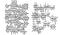
- Figure 1 shows a structural model of coal
- the left side shows a structural model of bituminous coal
- the right side sub-bituminous coal.
- the use of the group has been limited due to the high possibility of spontaneous combustion.
- Water in the lower coal is divided into free water, interstitial water (pore water), surface water, bound water and the like.
- Much of the lower coal moisture is free water attached to the surface of the lower coal, the water present between the molecules of the lower coal and the inner water, and the bound water is chemically bound to the lower coal molecules.
- Free water and surface water are dried at 100 ⁇ 5 ° C, but internal and bonded water are destroyed and dried at about 400 ° C. Therefore, it is difficult to maintain this high temperature up to low coal by conventional drying methods. .
- Figure 2 shows a conceptual diagram of the BCB technology of Australia, a representative technology of the drying technology, the conventional low-grade coal drying and safety technology as shown in Figure 2, a fluidized bed drying method to dry by heating for 1 hour at a temperature of 400 °C or more, It has a disadvantage of low thermal efficiency and high molding pressure of dry coal, and also has a disadvantage of long-term storage in low coal. Above all, since the water removal rate is very low, in the range of 15 to 20%, it is used for lowering the water content of 30% coal to 25% water content.
- An object of the present invention is a low grade coal having a water content of 30% or more, a calorific value of 4,500 kcal / kg or less, a ignition temperature of 180 ° C. or less, as a coal for power generation with a moisture content of 5% or less, a calorific value of 6,500 kcal / kg or more, and a ignition temperature of 230 ° C. or more. It is to provide a high quality device and method capable of high quality and significantly raising the firing temperature.
- Another object of the present invention is to dry the low-grade coal to a lower temperature than conventional, high-grade device that can meet the conditions as fuel of the standardized pulverized coal power plant by preventing oxygen adsorption when stored in a low coal storage through the formation of dry coal powder And a method.
- an oil vapor production unit for producing an oil vapor; And it is connected to the steam production unit provides a high quality coal coalescing apparatus including a steam drying unit for drying the lower coal using the oil vapor supplied from the steam production unit.
- the oil vapor production unit is connected to the exhaust gas supply, characterized in that the exhaust gas as a heat source.
- the exhaust gas supply source may be a general power plant or a oxy-fuel plant, and in particular, the oxy-fuel plant is preferable.
- the oxygen concentration in the exhaust gas is preferably 5% or less, the temperature of the exhaust gas may be 150 to 250 °C.
- Oil vapor production unit in the present invention is an oil storage tank for receiving oil and the oil is evaporated;
- An exhaust gas distributor installed inside the oil storage tank and connected to an exhaust gas source to distribute the exhaust gas to the oil storage tank;
- it may include a heater installed on the outer wall of the oil storage tank.
- the steam drying unit has a coal inlet and a coal outlet, and a drying chamber in which coal is dried;
- An oil vapor distributor installed inside the drying chamber and connected to the oil vapor production unit to distribute the oil vapor to the drying chamber;
- a microwave supplier installed in the drying chamber to irradiate microwaves;
- Vibration means installed on the lower portion of the drying chamber for vibrating the drying chamber;
- Vibration fluid plate installed in the drying chamber and made of a wave shape to induce the flow of coal by the vibration of the vibration means;
- an exhaust gas inlet connected to the exhaust gas source and installed at a lower portion of the vibrating fluid plate.
- a plurality of pores are formed at the inlet side of the exhaust gas, and the plurality of pores preferably form an angle of ⁇ 10 ° with the flow direction of the exhaust gas.
- the present invention is a power plant boiler;
- An oil vapor production unit configured to manufacture oil vapor as a heat source of exhaust gas discharged from a power plant boiler; And it is connected to the steam production unit provides a high quality coal system including a steam drying unit for drying the lower coal by using the oil vapor supplied from the steam production unit.
- the high quality coal coalification system includes a preheater installed at the rear end of the boiler and preheating air or oxygen supplied to the boiler by using exhaust gas discharged from the boiler as a heat source; And a condenser installed in a branch line branched from the exhaust gas treatment line and separating and removing water from the exhaust gas.
- the preheater of the coal derating system includes a main preheater for preheating air or oxygen supplied to a boiler; And an exhaust gas preheater connected to the condenser to preheat the exhaust gas from which moisture has been removed.
- the high-definition system of coal according to the present invention may further include a molding machine connected to the oil vapor drying unit for compression molding the dried coal.
- the present invention comprises the steps of (a) preparing the vapor; And (b) drying the lower coal using oil vapor.
- step (a) of the high-definition method according to the present invention it is preferable to produce oil vapor using exhaust gas as a heat source, and it is possible to transport oil vapor using exhaust gas as a propellant gas.
- step (b) of the high-definition method according to the present invention at least some of the oil vapor is condensed and adsorbed on the coal surface, thereby dissociating the internal water between the coal molecules and the bound water bonded to the coal molecule surface.
- the exhaust gas can be used for the drying heat source and the coal flow, the microwave can be irradiated with coal, and the coal can be vibrated.
- the high quality process according to the present invention comprises the steps of, before step (a), condensing exhaust gas to separate and remove moisture; And preheating the exhaust gas from which moisture has been removed, wherein the exhaust gas may be used as a heat source for preheating.
- the high quality process according to the invention may further comprise, after step (b), compression molding the dried coal.
- low-grade coal having a moisture content of 30% or more is dried to a temperature of 150 ° C. or less, which is 250 ° C. lower than 400 ° C. by applying steam vapor adsorption, microwave irradiation, and a coal-fired boiler or pure oxygen thermal power plant boiler exhaust gas heat source.
- steam vapor adsorption, microwave irradiation, and a coal-fired boiler or pure oxygen thermal power plant boiler exhaust gas heat source Through the shaping of the dry coal powder, it is possible to meet the conditions as a fuel of the standardized pulverized coal power plant by preventing oxygen adsorption when stored in the low coal.
- the oil condensed through the contact with the high moisture low-grade coal infiltrate into the pore of the coal to increase the repulsive force with the combined water inside the coal to dissociate moisture
- the oil condensed through the contact with the high moisture low-grade coal infiltrate into the pore of the coal to increase the repulsive force with the combined water inside the coal to dissociate moisture
- Figure 2 shows a conceptual diagram of the BCB technology of Australia, a typical technique of the drying technology.
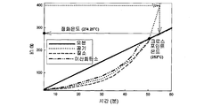
- 3 is a graph showing a change in temperature in coal according to time and gas type.
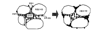
- Figure 4 shows the effect of the steam drying method on the combined moisture.
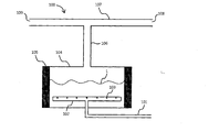
- FIG. 6 is a cross-sectional view of the oil vapor production unit according to the present invention.
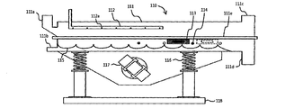
- FIG. 7 is a sectional view of an oil vapor drying unit according to the present invention.
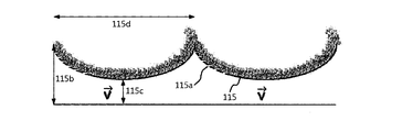
- FIG. 8 is a side cross-sectional view of the porous vibrating fluid plate installed in the steam drying unit according to the present invention.
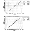
- 9 is a graph showing the measurement results of ignition temperatures of raw coal and high grade coal.
- FIG. 10 is a system diagram of the ignition temperature measuring apparatus.
- 11 is a graph showing changes in surface bond groups of raw coal and high grade coal.
- the present invention is a heat source application technology for drying moisture, unlike the direct heating method such as electric furnace and fluidized bed dryer, in the case of a pure coal fired coal-fired power plant in preparation for the CO2 boiler and climate change agreement, and the general coal-fired power plant boiler It is characterized in that the exhaust gas discharged after combustion is applied as a heat source.
- the present invention after preheating the exhaust gas containing coal ash, nitrogen oxides and sulfur oxides in the exhaust gas, for example, the exhaust gas containing 95% CO 2 preheated to 200 ° C or more through heat exchange in the preheater, the hot air exhaust gas for steam production It is used to decompose the combined water inside the low grade coal by supplying it to the heat source for drying high grade low grade coal. Characterized in that to prevent.
- the present invention is applied to the technique using the difference in the solubility (Wettability) of the combined moisture having affinity of the coal carbon component and the hydrophilic (Hydrophilic).
- the reaction mechanism uses adsorption characteristics through condensation of a certain amount of oil vapor to increase repulsion and repulsion between hydrophilic bonded water and carbon components of hydrophobic low grade coal. By increasing the surface tension and promoting decomposition with low grade coal.
- the application of oil vapor increases the decomposing power of the combined water such as the pore water and the capillary coupling water, even when the exhaust gas containing carbon dioxide is supplied at a temperature of 150 ° C. or lower, the combined water and the capillary coupling water are dried and ejected as steam. You can.
- the condensed oil is adsorbed in the pores, when the coal is compressed in the molding apparatus, the bonding force between the coals can be increased, and the adsorption of moisture and oxygen can be prevented, thereby greatly increasing the spontaneous ignition temperature.
- coal components having a low dielectric constant (permeability) have a property of transmitting microwaves.
- internal moisture such as polar solvent, which has a high transmittance, is evaporated while absorbing microwaves and releasing heat through its own molecular rotation.
- the high-grade system according to the present invention includes a boiler 10, a coal mill 20, and a preheater 30. ), Dust collector (40), blower (50), waste heat recovery system (60), desulfurization facility (70), stack (80), condenser (90), oil vapor production unit (100), oil vapor drying unit (110), dust collector 120, a molding machine 130, a low-charging cabinet 140, a powder mill 150, and the like.
- the boiler 10 is composed of a general power plant boiler or a pure oxygen power plant boiler.
- the exhaust gas generated after combustion in the boiler 10 enters the preheater 30 through an economizer 20 in a state containing ash and air pollutants.
- the preheater 30 includes a main preheater 31 for preheating the primary air A1 for supplying pulverized coal as fuel to the combustion boiler 10 and the secondary air A2 for combustion air, and increasing boiler efficiency; Characterized in that it consists of a drying exhaust gas preheating unit 32 for preheating the clean exhaust gas for low-grade coal drying and stabilization.
- the exhaust gas temperature discharged from the economizer 20 is 400 ° C. or more, and the exhaust gas temperature discharged from the rear end of the preheater 30 is lowered to about 150 ° C. through preheating of atmospheric air and drying air.
- the temperature of the atmospheric air (A) or high-purity oxygen (O) flowing into the combustion air is preheated in the atmospheric air preheater 31 to rise to 350 to 380 °C and then supplied to the primary and secondary air.
- the exhaust gas preheater 32 occupies 5% of the total preheater 30 and serves to preheat the exhaust gas to be supplied to the oil vapor production unit 100 and / or the steam dryer 110, and the exhaust gas preheater 32.
- the temperature of the exhaust gas passing through (32) is maintained at 150 to 250 ° C.
- the exhaust gas cooled to about 150 ° C. by heat transfer in the preheater 30 is introduced into a dust collector 40, for example, an electric dust collector, and coal ash and the like are collected and removed from the dust collector 40.
- a dust collector 40 for example, an electric dust collector, and coal ash and the like are collected and removed from the dust collector 40.
- the exhaust gas is absorbed through the blower 50 to the last residual heat in the waste heat recovery system 60, and then discharged through the stack 80 as clean air through the flue gas desulfurization facility 70, which is an air pollutant removing facility. do.
- the main feature of the present invention is the use of clean exhaust gas that has undergone dust collection and desulfurization.
- Clean exhaust gas has a composition of 25% CO 2 , H 2 O 5%, and N 2 70%.
- a branch line is preferably formed between the desulfurization plant 70 and the stack 80 in the flue gas treatment line, and then a condenser 90 is attached to the branch line. Install.
- the exhaust gas from which most of the moisture is removed through the condenser 90 is heated to 150 to 250 ° C. through heat exchange in the exhaust gas preheating unit 32 of the preheater 30. Used as a heat source of the oil vapor production unit 100 and the oil vapor drying unit 110.
- the exhaust gas used in the oil vapor drying unit 110 is introduced into the dust collector 120, the dust collected by the dust collector 120 is transferred to the molding machine 130, and the gas is recycled to the condenser 90 to remove moisture. .
- High moisture low grade coal (C) is, for example, 200 mesh passes through, is supplied to the upper end of the steam drying unit 110 is dried while moving slowly, then transferred to the molding machine 130 is compression molded and then low-charging 140 Stored in).
- the stored high quality coal is finely ground in the mill 150 and then used as fuel of the combustion boiler 10.
- the fine powder scattered by the exhaust gas from the oil vapor drying unit 110 is collected through the dust collector 120 and re-transmitted to the molding apparatus 130.
- high moisture low grade coal (C) having passed through 200 mesh is used as a raw material.
- the coal-fired power plant exhaust gas or oxygen-oxygen-fired power plant exhaust gas having an oxygen concentration of 5% or less recovered from the preheater 30 as a heat source, the surface water of the low-grade coal (C) is removed, After dissociating the internally bound coal through coal, the non-degradable water such as pore water, capillary coupling water, internally retained water, etc., which is decomposed and dried at 400 ° C. or higher, is dried at 150 ° C. or lower, and 5% moisture and 2 4 to 4% of the level of dry coal may be manufactured using high quality coal of 1.11 g / cm 3 or more through the molding machine 130 to prevent spontaneous ignition in the low coal 140.
- the oil vapor production unit 100 is the exhaust gas inlet pipe 101, exhaust gas distributor 102, injection port 103, oil storage tank 104, heater 105, And a connecting pipe 106, a nozzle 107, a nozzle inlet 108, a nozzle outlet 109, and the like.
- Oil (L) is stored in the oil storage tank 104, and oil (L) for steam production may include boiler kerosene, by-product fuel (haixin), and waste cooking oil.
- oil (L) for steam production may include boiler kerosene, by-product fuel (haixin), and waste cooking oil.
- the oil storage tank 104 should maintain a temperature of about 150 °C, for this purpose, a heater 105 may be installed on the outer wall of the oil storage tank 104.
- the exhaust gas preheated to about 200 ° C. in the preheater 30 is used as a heat source for producing steam, and the exhaust gas is introduced through the exhaust gas inlet pipe 101 and supplied to the inside of the oil storage tank 104 through the exhaust gas distributor 102. .
- the exhaust gas distributor 102 is disposed in the lower portion of the oil storage tank 104 in the longitudinal direction and / or the width direction so as to evenly inject the exhaust gas into the oil storage tank 104, and the plurality of injection holes formed at regular intervals Has 103.
- the exhaust gas of about 200 ° C. supplied through the internal distributor 102 promotes volatilization and decomposition of boiler kerosene, by-product fuel or waste cooking oil to generate oil vapor.
- the generated vapor is introduced into the nozzle 107 through the connecting pipe 106, and the exhaust gas is also introduced into the inlet 108 of the nozzle 107.
- the exhaust gas flowing into the nozzle 107 is used as a propellant gas and serves to transport oil vapor. That is, the exhaust gas is used as a heat source for producing steam in the vapor production unit 100, and is used as a propulsion gas for transporting vapor.
- exhaust gas must be injected instead of general air in order to prevent fire caused by oil vapor and static electricity.
- the oil vapor is discharged together with the exhaust gas to the outlet 109 of the nozzle 107 and then transferred to the oil vapor drying unit 110.
- the steam drying unit 110 is a drying chamber 111, coal inlet 111a, exhaust gas inlet 111b, gas Outlet 111c, coal outlet 111d, drying chamber connection 111e, vapor distributor 112, injection port 112a, microwave feeder 113, temperature sensor 114, vibrating fluid plate 115, pores 115a ), A vibration spring 116, a vibration feeder 117, a support 118 and the like.
- the drying chamber 111 may be composed of an upper drying chamber and a lower drying chamber formed long in the longitudinal direction, and the upper and lower drying chambers may be integrally formed through the connecting portion 111e.
- the drying chamber 111 is a coal inlet 111a for supplying low-grade coal at one upper end, an exhaust gas inlet 111b for supplying exhaust gas at one lower end, and a gas outlet for discharging oil, exhaust gas, steam, dust, etc. at the upper end of the other side ( 111c), and the other side of the lower end has a coal discharge port 111d through which the coal is discharged.
- An oil vapor distributor 112 is installed at an upper portion of the drying chamber 111, and the oil vapor distributor 112 is long over the longitudinal direction and / or the width direction of the drying chamber 111 so that the oil vapor may be evenly sprayed on the drying chamber 111. It is arranged, and has a plurality of injection holes 112a formed at regular intervals.
- the microwave supply 113 is installed at least one inside and / or outside of the drying chamber 111, and acts as a heat source for drying coal along with oil vapor and exhaust gas.
- At least one temperature sensor 114 is installed inside and / or outside the drying chamber 111 to measure the temperature of the drying chamber 111 and may be associated with the microwave supply 113. In detail, the temperature may be controlled by controlling the microwave supply 113 while monitoring the temperature inside the coal through the temperature sensor 114.
- Vibration fluid plate 115 is installed in the drying chamber 111, and made of a wave (Wave type) serves to induce the flow of coal by the vibration of the vibration means.
- Vibration means is installed in the lower portion of the drying chamber 111 to vibrate the drying chamber 111 to generate the flow of coal and the flow of coal, the vibration feeder 117 and the vibration spring 116 to generate vibration, etc. It is configured and supported by the support 118.
- the high moisture low grade coal (C) is introduced into the upper part of the drying chamber 111 through the coal inlet 111a using the one passed through the 200 mesh, and the oil vapor is supplied to the upper part of the drying chamber 111 through the oil vapor distributor 112. Injecting, the exhaust gas is supplied to the lower portion of the drying chamber 111 through the exhaust gas inlet (111b).
- Oil vapor primarily acts as a heat source for coal drying and serves to dry the surface water of coal. At the same time, the oil vapor is condensed through heat transfer with the coal surface and is converted into oil, adsorbing on the coal surface and the pores, thereby generating a repulsive force with the coal-bonded water and pore water.
- Flue gas also acts primarily as a heat source for coal drying, and also serves to induce the flow of coal while passing through the vibrating fluid plate 115.
- the microwave feeder 113 also acts as a heat source to facilitate binding water and pore water drying.
- oil vapor, flue gas, microwave, and the like act in combination to allow drying of coal even at a low temperature of 150 ° C or lower.
- coal flow by the complex action of the exhaust gas, vibrating fluid plate 115, vibrating means 116, 117, etc. it is possible to facilitate the drying of the coal more smoothly, and at the same time the coal outlet inlet 111a Can be moved toward 111d.
- the vibrating fluid plate 115 is formed with a plurality of pores 115a for the introduction of the exhaust gas, the pores (115a) is the propulsion direction (V) of the wave shape It is installed in the lower portion as a reference, and is formed to be in an angle of ⁇ 10 ° with the flow direction of the flue gas and coal, preferably parallel to, for preventing backflow and smooth contact.
- the size of the pores 115a is smaller than the size of the coal so that coal does not leak.
- the exhaust gas passes through the vibratory fluidizing plate 115 to promote the flow of coal.
- the oil vapor production apparatus is manufactured as shown in FIG. 6, but the oil storage tank 104 has a diameter of 30 cm and a height of 20 cm, and a 30 kW hot wire feeder is installed on the outer wall as a heater 105.
- the steam drying apparatus is manufactured as shown in FIG. 7, but the drying chamber 111 has a length of 300 cm, a width of 30 cm, and a height of 30 cm, and includes a coal inlet 111a, a gas outlet 111c, and a steam distributor 112.
- the inlet area was designed to be 2inch ⁇ 2inch, and the microwave supply 113 used a 2.45 GHz, 2 kW, 220 V, single phase, and a temperature sensor 114 using a stainless steel shielded thermocouple, but the temperature sensor 114 )
- the installation part diameter was 1 cm, and two vibration feeders 117 having a capacity of 0.45 kW were attached to both sides in order to uniformly vibrate the drying chamber 111.
- the vibrating fluid plate 115 is made in a wave shape using a Teflon material, as shown in FIG. 8, but the maximum distance 115 cm and 5 cm from the bottom of the drying chamber 111, the minimum distance 115 c and 2 cm and the wave width 115 d. ) was made in 5.5 cm, the pores (115a) was formed in the vertical direction with a size of 5 mm diameter and 1 cm left and right intervals on the left side of the wave shape.
- Oil vapor manufacturing raw materials boiler by-product fuel (Hisin)
- Oil vapor flue gas injection rate 0.18 ⁇ 0.36 m3 / min
- Second drying time 5 ⁇ 20 minutes
- the moisture content is about 36%, and the calorific value is 6,291 kcal / kg (dry), higher than that of anthracite, but lower than coal for coal-fired power plants (6,500 kcal / kg).
- the fuel cost is 0.86, which is similar to the sub-bituminous series, and it can be confirmed that it is suitable for the specification of thermal power plant when the moisture is dried below 10%.
- by-product fuel 1 (Hycin) for producing steam was composed of a density of 0.8091 g / cm 3, a flash point of 46.5 ° C., 0.05% of sulfur, a viscosity of 1.01 mm 2 / S, and a residual carbon amount of 0.01%.
- the produced high-grade coal showed a very low water content of less than 5.2%, and the heat content was very high, more than 7,140 kcal / kg. In particular, the fuel cost was greatly improved to 0.92 or more. From the physical properties of Table 1, it was found to be suitable as a raw material for burning coal-fired power plants.
- FIG. 9 is a graph showing the measurement results of ignition temperatures of the raw coal and the high grade coal, the left side of which is a high moisture low grade raw coal, and the right side which is an optimum dry high grade coal.
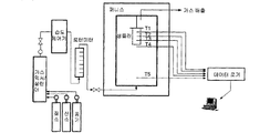
- the temperature increase apparatus was composed of a thermostat, a thermocouple, a temperature controller, a recorder and a sample container as shown in FIG.
- the thermostat is a hot air circulating thermostat with an internal volume of 90 L (45 cm ⁇ 45 cm ⁇ 45 cm), which is an improvement of a commercially available thermostat. Was forced to circulate, and two heaters of 1,000 W were used to heat the thermostat.
- the fan was installed in the exhaust port of the upper part of the thermostat so that the fan was operated by a relay switch when the internal temperature was higher than the set temperature.
- Thermocouples are two sets of Chromel-Alumel thermocouples used for controlling and measuring the ambient temperature and for measuring the center temperature of the sample. The diameter of the thermocouple was 0.35 mm.
- the temperature control window (EC-5600 manufactured by Konics) allows you to control the compensated temperature through the cold junction by controlling the ambient temperature by setting the program, and compares it with the set temperature. Current values were controlled and the operation of the upper fan was controlled on-off using a relay switch.
- CPT cross point temperature
- Table 2 shows the properties and the ignition temperature of high quality coal by experimental process conditions.
- the moisture removal rate is (35% ⁇ 5%) more than 85%.
- the concentration of oxygen functional groups on the surface of the coal was lowered and moisture and oxygen adsorption were prevented during storage of low coal.
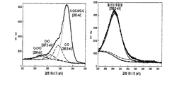
- FIG. 11 is a graph showing surface changer changes of the raw coal and the high-grade coal, the left side is a high moisture low grade coal raw material, and the right side is a vapor-dried high quality coal.
- XPS X-ray photoelectron spectroscopy
- drying time it is possible to shorten the drying temperature to 150 ° C. or less and to improve the ignition temperature to 230 ° C. or more.
- according to the present invention can solve the problems such as economical degradation and excessive power consumption of the conventional low-grade coal drying apparatus, combustion problems that occur when using high-quality coal.
- Korea imported about 80 million tons of high grade bitumen coal in 2007, and is the second largest importer of coal after Japan. Of the 80 million tons, approximately 57 million tons are used for power generation only. Therefore, in the case of Korea, which imports a huge amount of coal in the future, the present invention can be applied for more than 50 years due to import substitution effect.
- the high quality coal produced through the high quality of the low grade coal according to the present invention can be applied for coal and mixed combustion in the thermal power plant.
- the present invention is applicable to coal-fired industries such as Indonesia, China, and Australia, where all coal-fired power plants (including domestic and foreign power plants) using coal as fuel, and a large amount of low grade coal are buried.
- the present invention is a technology for producing high grade coal (HRC) of the same grade as bituminous coal by high-quality with respect to lignite (LRC) that is not used due to high moisture and spontaneous combustion, and through the present invention coal
- HRC high grade coal
- LRC lignite
- Table 3 shows the coal usage forecast, technology development and import reduction forecast.
- the present invention can be prepared for oil shocks, and the price fluctuations are severe and can reduce the import price of coal, which occupies more than 70% of the unit cost, the potential growth is very high.
Landscapes
- Chemical & Material Sciences (AREA)
- Engineering & Computer Science (AREA)
- Organic Chemistry (AREA)
- Oil, Petroleum & Natural Gas (AREA)
- Mechanical Engineering (AREA)
- General Engineering & Computer Science (AREA)
- Thermal Sciences (AREA)
- Combustion & Propulsion (AREA)
- Physics & Mathematics (AREA)
- Materials Engineering (AREA)
- Life Sciences & Earth Sciences (AREA)
- Microbiology (AREA)
- Solid Fuels And Fuel-Associated Substances (AREA)
Abstract
본 발명은 수분함량 30% 이상, 발열량 4,500 kcal/kg 이하, 발화온도 180℃ 이하의 저등급 석탄을 수분 5% 이하, 6,500 kcal/kg 이상, 발화온도 230℃ 이상의 발전용 석탄으로 고품위화하고 발화온도를 대폭 상승시키는 장치와 방법에 관한 것이다.
Description
본 발명은 수분 함량이 30 내지 60%인 저등급 석탄을 석탄화력 발전소의 연료로서 사용하기 위한 고품위화 장치 및 방법에 관한 것으로, 더욱 상세하게는 예열 배가스를 열원으로 소수성(Hydrophobic) 유증기의 흡착을 통해 기존 400℃보다 250℃ 이상 낮은 150℃ 이하의 온도로 저등급 석탄을 건조하고, 유증기의 흡착 침투 및 표면 코팅 특성을 이용해 자연발화를 방지함으로써 미분탄 발전소의 혼합연료로서 조건을 맞출 수 있는 고수분 저등급 석탄의 고품위화 장치 및 방법에 관한 것이다.
고수분 고회분 갈탄(저등급, LRC: Low Rank Coal)으로부터 탈수, 건조 및 안정화를 통해 역청탄급 석탄(고등급, HRC: High Rank Coal)으로 연료화하는 기술(LRC → HRC)을 고품위화 기술이라고 정의한다.
고품위화에 따라, 수분 30% 이상의 갈탄은 수분 10% 이하의 고품위화 석탄이 되고, 고위 발열량(HHV: Higher Heating Value)은 4,500 kcal/kg 이하에서 6,500 kcal/kg 이상으로 되며, 발화온도는 180℃ 이하에서 210℃ 이상으로 된다.
갈탄은 수분이 많고 자연발화 가능성이 매우 높다. 도 1은 석탄의 구조 모델을 나타낸 것으로, 좌측은 역청탄, 우측은 아역청탄의 구조 모델을 나타낸 것이다. 도 1에서 보는 바와 같이, 저등급 석탄에는 기공이 많고 가지 탄화수소(peripheral hydrocarbon: 휘발분)가 많기 때문에, 수분의 흡-탈착에 의한 흡착열의 축적으로 온도가 상승되고, 휘발분 중의 상당량을 차지하고 있는 산소 기능성 그룹으로 인해 자연발화 가능성이 높아서 사용이 제한되어 왔다.
저급 석탄 내의 수분은 자유수(free water), 내부수(interstitial water; 간극수), 표면수(surface water), 결합수(bound water) 등으로 구분된다. 저급 석탄 수분 중 상당 부분을 차지하고 있는 것은 저급 석탄 표면에 부착되어 있는 자유수이고, 저급 석탄의 분자와 분자 사이에 존재하는 수분이 내부수이며, 결합수는 저급 석탄 분자에 화학적으로 결합되어 있다. 자유수와 표면수는 100±5℃에서 건조되지만, 내부수와 결합수는 약 400℃에서 파괴 및 건조가 일어나므로, 기존의 건조방법으로는 저급 석탄 내부까지 이 높은 온도를 유지하기가 곤란하다.
또한, 저등급 석탄 건조를 통한 고품위화시 석탄의 기공에는 주로 산소 산화 반응기들, 예를 들어 수산기(Hydroxyl groups, -OH), 카르복실기(Carboxyl group, -CH-OH-), 카르보닐기(Carbonyl group, -C=O)가 생성된다. 이들은 결국 공기 중에 노출 시 수분 및 산소 성분과 반응하여 산화되면서 기공 내부의 온도를 상승시켜 자연 발화의 원인이 된다. 따라서, 대부분의 고품위화 기술에 있어서, 건조 공정을 통해 수분 함량 10% 이하로 건조된 석탄에 대해 자연발화 문제의 해결이 필수적이다.
도 2는 건조기술의 대표적인 기술인 호주의 BCB 기술 개념도를 나타낸 것인데, 기존의 저등급 석탄의 건조 및 안전화 기술은 도 2와 같이, 400℃ 이상의 온도에서 1시간 동안 가열하여 건조하는 유동층 건조방식으로, 열효율이 낮고 건조탄의 성형압력이 높은 단점이 있으며, 또한 저탄장에서의 장기 보관이 어려운 단점이 있다. 무엇보다도 수분 제거율이 15 내지 20% 범위로서 매우 낮기 때문에, 수분 함량 30%의 석탄을 수분 함량 25%로 낮추는 곳에 사용되고 있다.
본 발명의 목적은 수분 함량 30% 이상, 발열량 4,500 kcal/kg 이하, 발화온도 180℃ 이하의 저등급 석탄을 수분 함량 5% 이하, 발열량 6,500 kcal/kg 이상, 발화온도 230℃ 이상의 발전용 석탄으로 고품위화하고 발화온도를 대폭 상승시킬 수 있는 고품위화 장치 및 방법을 제공하는 것이다.
본 발명의 다른 목적은 저등급 석탄을 기존보다 낮은 온도로 건조하고, 건조탄 분말의 성형을 통해 저탄장에 저장시 산소흡착을 방지함으로써, 표준화력 미분탄 발전소의 연료로서 조건을 맞출 수 있는 고품위화 장치 및 방법을 제공하는 것이다.
본 발명은 상기 목적을 달성하기 위하여, 유증기를 제조하는 유증기 제조부; 및 유증기 제조부와 연결되어 유증기 제조부로부터 공급받은 유증기를 이용하여 저급 석탄을 건조하는 유증기 건조부를 포함하는 석탄의 고품위화 장치를 제공한다.
본 발명에서 유증기 제조부는 배가스 공급원과 연결되어 배가스를 열원으로 하는 것을 특징으로 한다.
본 발명에서 배가스 공급원은 일반 발전소 또는 순산소 발전소일 수 있으며, 특히 순산소 발전소인 것이 바람직하다.
본 발명에서 배가스 중 산소농도는 5% 이하인 것이 바람직하며, 배가스의 온도는 150 내지 250℃일 수 있다.
본 발명에서 유증기 제조부는 기름을 수용하고 기름의 증발이 이루어지는 기름 저장탱크; 기름 저장탱크 내부에 설치되고 배가스 공급원과 연결되어 기름 저장탱크에 배가스를 분배하는 배가스 분배기; 기름 저장탱크 및 배가스 공급원과 각각 연결되어 기름 저장탱크에서 형성된 유증기를 배가스의 추진으로 배출하는 노즐; 및 기름 저장탱크의 외벽에 설치되는 가열기를 포함할 수 있다.
본 발명에서 유증기 건조부는 석탄 투입구 및 석탄 배출구를 가지며, 석탄의 건조가 이루어지는 건조실; 건조실 내부에 설치되고 유증기 제조부와 연결되어 건조실에 유증기를 분배하는 유증기 분배기; 건조실에 설치되어 마이크로파를 조사하는 마이크로파 공급기; 건조실의 하부에 설치되어 건조실을 진동시키는 진동수단; 건조실 내부에 설치되고 물결모양으로 이루어져 진동수단의 진동에 의해 석탄의 유동을 유도하는 진동 유동판; 및 배가스 공급원과 연결되고 진동 유동판의 하부에 설치되는 배가스 유입구를 포함할 수 있다.
본 발명에 따른 유증기 건조부 중 진동 유동판에는 다수의 기공이 배가스 유입구 쪽에 형성되고, 다수의 기공은 배가스의 흐름방향과 ±10°의 각도를 이루는 것이 바람직하다.
또한, 본 발명은 발전소 보일러; 발전소 보일러에서 배출되는 배가스를 열원으로 유증기를 제조하는 유증기 제조부; 및 유증기 제조부와 연결되어 유증기 제조부로부터 공급받은 유증기를 이용하여 저급 석탄을 건조하는 유증기 건조부를 포함하는 석탄의 고품위화 시스템을 제공한다.
본 발명에 따른 석탄의 고품위화 시스템은 보일러의 후단에 설치되고 보일러에서 배출되는 배가스를 열원으로 보일러에 공급되는 공기 또는 산소를 예열하는 예열기; 및 배가스 처리라인에서 분지되는 분지라인에 설치되고, 배가스 중 수분을 분리 제거하는 응축기를 추가로 포함할 수 있다.
본 발명에 따른 석탄의 고품위화 시스템 중 예열기는 보일러에 공급되는 공기 또는 산소를 예열하는 주예열부; 및 응축기와 연결되어 수분이 제거된 배가스를 예열하는 배가스 예열부를 포함할 수 있다.
본 발명에 따른 석탄의 고품위화 시스템은 유증기 건조부와 연결되어 건조된 석탄을 압축 성형하는 성형기를 추가로 포함할 수 있다.
또한, 본 발명은 (a) 유증기를 제조하는 단계; 및 (b) 유증기를 이용하여 저급 석탄을 건조하는 단계를 포함하는 석탄의 고품위화 방법을 제공한다.
본 발명에 따른 고품위화 방법 중 (a) 단계에서는 배가스를 열원으로 하여 유증기를 제조하는 것이 바람직하고, 또한 배가스를 추진가스로 하여 유증기를 운반할 수 있다.
본 발명에 따른 고품위화 방법 중 (b) 단계에서는 적어도 일부의 유증기는 석탄 표면에서 응축되어 흡착됨으로써, 석탄 분자 사이의 내부수와 석탄 분자 표면에 결합된 결합수를 해리시키는 것을 특징으로 한다.
본 발명에 따른 고품위화 방법 중 (b) 단계에서는 배가스를 건조 열원 및 석탄 유동용으로 사용할 수 있고, 석탄에 마이크로파를 조사할 수 있으며, 석탄을 진동시킬 수 있다.
본 발명에 따른 고품위화 방법은 (a) 단계 이전에, 배가스를 응축하여 수분을 분리 제거하는 단계; 및 수분이 제거된 배가스를 예열하는 단계를 추가로 포함할 수 있으며, 이때 예열의 열원으로 배가스를 이용할 수 있다.
본 발명에 따른 고품위화 방법은 (b) 단계 이후에, 건조된 석탄을 압축 성형하는 단계를 추가로 포함할 수 있다.
본 발명에서는 수분함량 30% 이상인 저등급 석탄을 유증기 흡착, 마이크로파 조사 및 석탄화력 보일러 혹은 순산소 화력발전소 보일러 배가스 열원 적용을 통해, 기존 400℃보다 250℃ 정도 낮은 150℃ 이하의 온도로 건조하고, 건조탄 분말의 성형을 통해 저탄장에 저장 시 산소흡착을 방지하여 표준화력 미분탄 발전소의 연료로서 조건을 맞출 수 있다.
저등급 석탄의 경우, 105±5℃ 범위에서 건조가 이루어지는 외부의 자유수분과 표면 부착수가 존재하는 반면에, 석탄 내부에 화학 결합된 간극수, 모관결합수, 내부 보유수는 400℃ 이상의 온도에서 1시간 이상 건조해야만 분해 및 건조된다.
종래와 같이 400℃ 이상의 고온 고압에서 건조하는 방식의 경우, 건조과정에서 휘발분의 탈휘발화에 따라 연소 연료가치가 떨어지고, 건조과정에서 불필요한 열량소비가 많으며, 건조탄의 표면에서 수분의 탈착으로 인해 생성된 다공에 산소흡착으로 인한 자연발화 발생의 문제점이 발생하고 있다.
따라서, 이와 같은 문제점들은 개선하기 위해 개발된 본 발명에서는, 유증기가 고수분 저등급 석탄과의 접촉을 통해 응축된 유분이 석탄의 다공으로 침투하면서 석탄 내부 결합수와의 반발력을 증가시켜 수분을 해리한 다음, 마이크로파 조사를 통해 건조함으로써, 150℃ 이하의 낮은 온도에서 20분 가량 짧은 시간에 빠른 속도로 건조함과 동시에, 발화온도를 230℃ 이상으로 상승시킬 수 있다.
도 1은 석탄의 구조 모델을 나타낸 것이다.
도 2는 건조기술의 대표적인 기술인 호주의 BCB 기술 개념도를 나타낸 것이다.
도 3은 시간 및 가스 종류에 따른 석탄 내 온도 변화를 나타낸 그래프이다.
도 4는 유증기 건조방식이 결합수분에 미치는 영향을 나타낸 것이다.
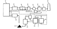
도 5는 본 발명에 따른 저등급 석탄의 고품위화 공정도이다.
도 6은 본 발명에 따른 유증기 제조부의 단면도이다.
도 7은 본 발명에 따른 유증기 건조부의 단면도이다.
도 8은 본 발명에 따라 유증기 건조부 내부에 설치된 다공성 진동 유동판의 측단면도이다.
도 9는 원료탄 및 고품위화탄의 발화온도 측정결과를 나타낸 그래프이다.
도 10은 발화온도 측정장치 계통도이다.
도 11은 원료탄과 고품위화탄의 표면 결합기 변화를 나타낸 그래프이다.
본 발명은 수분 건조 시 열원 적용기술로서, 전기로 및 유동층 건조기와 같은 직접 가열방식과 달리, 일반 석탄화력 발전소 보일러 혹은 기후변화 협약을 대비하고 이산화탄소 회수를 위해 개발 중인 순산소 보일러형 석탄화력 발전소에서 연소 후 배출되는 배가스를 열원으로 적용한 것을 특징으로 한다.
또한, 본 발명은 배가스 중 석탄회, 질소산화물 및 황산화물을 제거한 청정 배가스, 예를 들어 95% CO2를 함유하는 배출가스를 예열기에서 열교환을 통해 200℃ 이상으로 예열시킨 후, 열풍 배가스를 유증기 제조용 및 고수분 저등급 석탄의 건조용 열원으로 공급하여 저등급 석탄 내부의 결합수를 분해하기 위해 사용하며, 설비적으로는 고른 열 접촉을 위한 최적 열풍식 다공판을 이용해 건조효율을 증가시키고 자연발화를 방지하는 것을 특징으로 한다.
순산소 보일러의 경우 석탄화력 발전소와 달리, 공기 중 질소 가스를 분리하여 얻은 98% 이상의 산소를 연소용 원료로서 이용하고 배가스를 재순환하기 때문에, 최종 배출되는 배출가스는 역청탄 1 kg 연소시 연소부산물 조성의 경우 통상 CO2 95%, H2O 2%, N2 3% 정도이며, 운전시 덕트에서 O2가 누설되는 것을 고려할 경우에는 CO2 95%, H2O 2%, N2 1%, O2 2% 정도로 분포하게 된다.
따라서, 순산소 발전소 배가스의 경우 건조시 활성산소가 거의 없기 때문에, 건조 공정에 열원으로 사용하거나, 미분기에 1차 공기로서 200℃ 이상의 열풍가스를 공급해도 자연발화를 방지할 수 있는 장점이 있다.
특히, 이산화탄소의 경우 자연발화 실험 결과, 도 3과 같이 가스 복사열 전달 특성치(Gas emissivity)가 높기 때문에, 질소 혹은 알곤과 같은 비활성 가스보다 석탄에 대한 열전달율이 높고, 자연발화 연소에 의한 온도상승 현상이 없는 것으로 나타났다.
즉, 순산소 보일러에서 배출되는 배출가스를 응축하여 수분을 제거함으로써, 이산화탄소 농도를 95% 이상으로 농축한 후, 배가스 재열기를 이용해 건조용 가스로서 공급할 경우, 건조효율을 상승시키고 건조온도를 200℃ 이상으로 공급해도 자연발화에 의한 화재발생의 문제점은 완벽하게 해결할 수 있다.
또한, 순산소 보일러 혹은 석탄화력 발전소 보일러의 배가스를 열원으로 유증기를 제조할 경우, 유증기의 폭발 및 발화를 방지할 수 있다. 등유, 부생연료 및 폐 식용유를 원료로 하여 유증기를 제조할 경우, 순산소 배가스의 온도는 200 내지 250℃, 석탄화력 배가스는 180 내지 220℃가 적정한 것으로 나타났다. 이것은 석탄화력발전소의 배가스 내 산소농도에 좌우됨을 확인할 수 있었다.
특히, 도 4와 같이 유증기를 만들어 고수분 저등급 석탄의 열원으로 공급할 경우, 저온의 석탄 표면에서 유증기가 응축되어 저급탄 기공에 침투하면서 흡착되고, 저급탄 내부의 결합수 및 간극수와의 소수성을 발휘하면서 반발력을 발생시킴으로써, 150℃ 이하의 저온에서도 간극수 및 결합수를 분해할 수 있게 해 준다.
즉, 소수성(Hydrophobic)을 갖는 유증기는 응축 시 유분으로 되는데, 본 발명은 석탄 탄소성분의 친화력과 친수성(Hydrophilic)을 갖는 결합수분의 가용성(Wettability) 차이를 이용하는 기술을 적용한 것이다.
한편, 반응 메카니즘은 친수성의 결합수분과 소수성인 저등급 석탄의 탄소성분 사이의 척력, 반발력(Repulsion)을 높이기 위하여, 일정량의 유증기의 응축을 통한 흡착특성을 이용하는데, 이들은 결합수분과의 소수성을 증가시키고 표면장력을 증가시킴으로써 저등급 석탄과의 분해를 촉진시킨다.
이와 같이, 유증기의 적용으로 인해 간극수 및 모관결합수와 같은 결합수분의 분해력이 높아지므로, 이산화탄소 성분의 배가스를 150℃ 이하의 온도로 공급하여도, 결합수분 및 모관결합수를 건조시켜 증기로서 분출시킬 수 있다.
또한, 기공에는 응축 유분이 흡착되기 때문에, 성형장치에서 석탄을 압축할 때 석탄끼리의 결합력을 증가시키고, 수분 및 산소 흡착을 방지하여 자연발화 온도를 대폭 상승시킬 수 있다.
한편, 유증기 건조 시 마이크로파를 조사할 경우, 유전율(투과도)이 낮은 석탄성분은 마이크로파를 투과하는 특성을 가진다. 반면에, 투과율이 높은 극성용매인 물과 같은 내부수분(간극수, 결합수)의 경우, 마이크로파를 흡수하여 자체 분자회전을 통해 열을 방출하면서 증발된다.
이하, 본 발명을 도면을 참조하여 상세히 설명한다.
도 5는 본 발명에 따라 저등급 석탄을 원료로 하여 석탄화력 발전소 연소용 고품위화 석탄을 제조하는 계통도로서, 본 발명에 따른 고품위화 시스템은 보일러(10), 절탄기(20), 예열기(30), 집진기(40), 송풍기(50), 폐열회수 시스템(60), 탈황설비(70), 연돌(80), 응축기(90), 유증기 제조부(100), 유증기 건조부(110), 집진기(120), 성형기(130), 저탄장(140), 미분기(150) 등으로 구성된다.
보일러(10)는 일반 발전소 보일러 또는 순산소 발전소 보일러로 구성된다. 보일러(10)에서 연소 후 발생된 배기가스는 회분 및 대기 오염물질을 함유한 상태로 절탄기(economizer)(20)를 거쳐 예열기(30)로 들어간다.
예열기(30)는 연소용 보일러(10)에 연료인 미분탄을 공급하는 1차 공기(A1)와 연소용 공기인 2차 공기(A2)를 예열하여 보일러 효율을 높이는 주예열부(31)와, 저등급 석탄 건조 및 안정화를 위한 청정 배기가스를 예열하는 건조용 배가스 예열부(32)로 구성됨을 특징으로 한다.
통상, 절탄기(20)에서 배출되는 배가스 온도는 400℃ 이상이며, 예열기(30) 후단에서 배출되는 배가스 온도는 대기공기 및 건조용 공기 예열을 통해 150℃ 정도로 낮아진다. 한편, 연소용 공기로 유입되는 대기공기(A) 또는 고순도 산소(O)의 온도는 대기공기 예열부(31)에서 예열되어 350 내지 380℃로 상승한 후 1차 및 2차 공기로 공급된다.
배가스 예열부(32)는 전체 예열기(30)의 5% 공간을 차지하며, 유증기 제조부(100) 및/또는 유증기 건조부(110)에 공급될 배기가스를 예열하는 역할을 하며, 배가스 예열부(32)를 통과한 배가스의 온도는 150 내지 250℃로 유지되도록 한다.
한편, 예열기(30)에서 열 전달에 의해 150℃ 정도로 냉각된 배가스는 집진기(40), 예를 들어 전기 집진기로 유입되고, 집진기(40)에서 석탄회 등이 포집되어 제거된다.
이후, 배가스는 송풍기(50)를 거처 폐열회수시스템(60)에서 마지막 잔열까지 흡수된 후, 대기오염 물질 제거설비인 배연탈황설비(70)를 거쳐 최종적으로 청정공기로서 연돌(80)을 통해 배출된다.
본 발명의 주요 특징은 집진 및 탈황공정을 거친 청정 배기가스를 이용하는 점이다.
청정배기가스의 경우 CO2 25%, H2O 5%, N2 70%의 가스 조성을 가지고 있으며, 순산소 보일러 배가스의 경우 CO2 95%, H2O 2%, N2 3%로 조성된다.
따라서, 배가스 중 5% 정도의 수분을 제거하기 위해, 배가스 처리라인 중, 바람직하게는 탈황설비(70)와 연돌(80) 사이에 분지라인을 형성한 후, 이 분지라인에 응축기(90)를 설치한다.
응축기(90)를 통해 대부분의 수분이 제거된 배기가스는 상술한 바와 같이, 예열기(30)의 배가스 예열부(32)에서 열교환을 통해 150 내지 250℃로 가열된 후, 본 발명의 핵심 구성인 유증기 제조부(100)와 유증기 건조부(110)의 열원으로 사용된다.
유증기 건조부(110)에서 사용된 배기가스는 집진기(120)로 유입되며, 집진기(120)에서 포집된 분진은 성형기(130)로 이송되고, 가스는 응축기(90)로 재순환되어 수분이 제거된다.
고수분 저등급 석탄(C)은 예를 들어 200 mesh 통과분이 사용되고, 유증기 건조부(110)의 상단으로 공급되어 서서히 이동하면서 건조된 후, 성형기(130)로 이송되어 압축 성형된 다음 저탄장(140)에 보관된다.
보관된 고품위 석탄은 미분기(150)에서 미분된 후, 연소보일러(10)의 연료로서 사용된다. 유증기 건조부(110)에서 배가스에 의해 비산되는 미세분말은 집진기(120)를 통해 포집되어 성형장치(130)로 재이송된다.
이와 같이, 수분함량이 30% 이상인 저등급 석탄을 수분 함량 10% 이하의 석탄화력발소 연소용 고품위화 석탄으로 건조하기 위해, 200 mesh를 통과한 고수분 저등급탄(C)을 원료로 하고, 예열기(30)에서 열을 회수한 산소농도 5% 이하의 석탄화력 발전소 배기가스 혹은 순산소 화력발전소 배기가스를 열원으로 적용함으로써, 저등급 석탄(C)의 표면수를 제거함과 동시에, 유증기의 접촉을 통해 석탄 내부 결합수를 해리시킨 다음, 400℃ 이상에서 분해 및 건조가 이루어지는 간극수, 모관결합수, 내부 보유수 등과 같은 난분해성 수분을 150℃ 이하에서 건조하며, 수분 5%, 기름 흡착량 2 내지 4% 수준의 건조탄을 성형기(130)를 통해 1.11 g/㎤ 이상의 고품위화 석탄으로 제조하여 저탄장(140)에서 자연발화를 방지할 수 있다.
도 6은 본 발명에 따른 유증기 제조부의 단면도로서, 유증기 제조부(100)는 배가스 유입관(101), 배가스 분배기(102), 분사구(103), 기름 저장탱크(104), 가열기(105), 연결관(106), 노즐(107), 노즐 입구(108), 노즐 출구(109) 등으로 구성된다.
기름 저장탱크(104)에는 기름(L)이 저장되며, 유증기 제조용 기름(L)으로는 보일러 등유, 부생연료(하이신) 및 폐식용유 등을 사용할 수 있다. 이때, 기름 저장탱크(104)는 150℃ 정도의 온도를 유지하여야 하는데, 이를 위해 기름 저장탱크(104)의 외벽에는 가열기(105)가 설치될 수 있다.
예열기(30)에서 200℃ 정도로 예열된 배가스가 유증기 제조용 열원으로 사용되는데, 배가스는 배가스 유입관(101)을 통해 유입되고, 배가스 분배기(102)를 통해 기름 저장탱크(104)의 내부에 공급된다.
배가스 분배기(102)는 배가스를 기름 저장탱크(104)에 고루 분사할 수 있도록, 기름 저장탱크(104)의 하부에 길이 방향 및/또는 폭 방향에 걸쳐서 길게 배치되며, 일정한 간격으로 형성된 다수의 분사구(103)를 갖는다.
내부 분배기(102)를 통해 공급된 200℃ 정도의 배가스는 보일러 등유, 부생연료 혹은 폐식용유의 휘발화 및 분해를 촉진시켜 유증기를 발생시킨다.
발생된 유증기는 연결관(106)을 통해 노즐(107)로 유입되는데, 노즐(107)의 입구(108)로 배가스가 또한 유입된다. 이때 노즐(107)로 유입되는 배가스는 추진가스로 사용되어 유증기를 운반하는 역할을 한다. 즉, 배가스는 유증기 제조부(100)에서 유증기 제조용 열원으로 사용됨과 동시에, 유증기 운반용 추진가스로 사용된다. 또 다른 측면에서, 유증기 및 정전기에 의한 화재 발생을 막기 위해서는, 일반 공기 대신 반드시 배가스를 주입해야 한다.
유증기는 배가스와 함께 노즐(107)의 출구(109)로 배출된 후 유증기 건조부(110)로 이송된다.
도 7은 본 발명의 핵심 구성요소인 유증기 및 마이크로파 건조방식 그리고 유동 반응식 유증기 건조부의 상세도로서, 유증기 건조부(110)는 건조실(111), 석탄 투입구(111a), 배가스 유입구(111b), 가스 배출구(111c), 석탄 배출구(111d), 건조실 연결부(111e), 유증기 분배기(112), 분사구(112a), 마이크로파 공급기(113), 온도센서(114), 진동 유동판(115), 기공(115a), 진동 스프링(116), 진동 공급기(117), 지지대(118) 등으로 구성된다.
건조실(111)은 길이 방향으로 길게 형성된 상부 건조실과 하부 건조실로 구성될 수 있고, 상부와 하부 건조실은 연결부(111e)를 통해 일체로 형성될 수 있다.
건조실(111)은 일측 상단에 저급 석탄이 공급되는 석탄 투입구(111a), 일측 하단에는 배가스가 공급되는 배가스 유입구(111b), 다른 일측 상단에는 유증기, 배가스, 수증기, 분진 등이 배출되는 가스 배출구(111c), 그리고 다른 일측 하단에는 건조탄이 배출되는 석탄 배출구(111d)를 갖는다.
건조실(111)의 상부에는 유증기 분배기(112)가 설치되는데, 유증기 분배기(112)는 유증기를 건조실(111)에 고루 분사할 수 있도록, 건조실(111)의 길이 방향 및/또는 폭 방향에 걸쳐서 길게 배치되며, 일정한 간격으로 형성된 다수의 분사구(112a)를 갖는다.
마이크로파 공급기(113)는 건조실(111)의 내부 및/또는 외부에 적어도 하나 이상 설치되며, 유증기 및 배가스와 더불어 석탄 건조용 열원으로 작용한다.
온도센서(114)는 건조실(111)의 내부 및/또는 외부에 적어도 하나 이상 설치되어 건조실(111)의 온도를 측정하며, 마이크로파 공급기(113)와 연계될 수 있다. 구체적으로, 온도센서(114)를 통해 석탄 내부의 온도를 모니터링하면서 마이크로파 공급기(113)를 제어하여 온도를 조절할 수 있다.
진동 유동판(115)은 건조실(111) 내부에 설치되고, 물결모양(Wave type)으로 이루어져서 진동수단의 진동에 의해 석탄의 유동을 유도하는 역할을 한다.
진동수단은 건조실(111)의 하부에 설치되어 건조실(111)을 진동시켜 석탄의 유동 및 석탄의 흐름을 발생시키는 역할을 하며, 진동을 발생시키는 진동 공급기(117) 및 진동 스프링(116) 등으로 구성되며, 지지대(118)에 의해 지지된다.
고수분 저등급 석탄(C)은 200 mesh를 통과한 것을 사용하여 석탄 투입구(111a)를 통해 건조실(111)의 상부에 투입하고, 유증기는 유증기 분배기(112)를 통해 건조실(111)의 상부에 분사하며, 배가스는 배가스 유입구(111b)를 통해 건조실(111)의 하부에 공급한다.
유증기는 일차적으로 석탄 건조용 열원으로 작용하여 석탄의 표면수를 건조시키는 역할을 한다. 동시에, 유증기는 석탄 표면과의 열전달을 통해 응축되어 유분으로 변하면서 석탄 표면 및 기공 내부에 흡착됨으로써, 석탄 내부 결합수 및 간극수와의 반발력을 발생시키는 역할도 한다.
배가스도 일차적으로 석탄 건조용 열원으로 작용함과 동시에, 이차적으로 진동 유동판(115)을 통과하면서 석탄의 유동을 유도하는 역할도 한다.
마이크로파 공급기(113)도 열원으로 작용하여 결합수 및 간극수 건조를 보다 용이하게 한다.
이와 같이, 유증기, 배가스 및 마이크로파 등이 복합적으로 작용해서 150℃ 이하의 저온에서도 석탄의 건조가 가능하다.
또한, 배가스, 진동유동판(115), 진동수단(116, 117) 등의 복합적인 작용으로 석탄을 유동시킴으로써, 석탄의 건조를 더욱 원활하게 촉진시킬 수 있으며, 아울러 석탄을 투입구(111a) 쪽에서 배출구(111d) 쪽으로 이동시킬 수 있다.
도 8은 본 발명에 따른 진동 유동판의 단면도로서, 진동 유동판(115)에는 배가스의 유입을 위한 다수의 기공(115a)이 형성되는데, 이 기공(115a)은 물결모양 중 추진방향(V) 기준으로 하강부에 설치되며, 역류방지 및 원활한 접촉을 위해 배가스 및 석탄의 흐름방향과 ±10°의 각도를 이루도록, 바람직하게는 평행이 되도록 형성된다. 기공(115a)의 크기는 석탄이 누출되지 않도록 석탄의 크기보다 작다. 이 기공(115a)를 통해 배가스가 진동유동판(115)를 통과하면서 석탄의 유동을 도모하게 된다.
본 발명에 따라 저등급 석탄으로부터 고품위화 석탄을 얻기 위한 장치와 방법을 실시예를 들어 설명하면 다음과 같다.
[실시예]
유증기 제조장치는 도 6과 같이 제작하되, 기름 저장탱크(104)는 지름 30 ㎝ 및 높이 20 ㎝의 크기로 구성하였고, 외벽에는 가열기(105)로서 30 kw의 열선 공급기를 설치하였다.
유증기 건조장치는 도 7과 같이 제작하되, 건조실(111)은 길이 300 ㎝, 넓이 30 ㎝, 높이 30 ㎝의 크기로 구성하였고, 석탄 투입구(111a), 가스 배출구(111c) 및 유증기 분배기(112) 유입구의 면적은 2inch×2inch로 설계하였으며, 마이크로파 공급기(113)로는 2.45 GHz, 2 kW, 220 V, 단상인 것을 사용하였고, 온도센서(114)로는 스테인리스 스틸 차폐 열전대를 사용하되, 온도센서(114) 설치부위 직경은 1 ㎝로 구성하였으며, 건조실(111)을 균일하게 진동시키기 위해 0.45 kW 용량의 진동 공급기(117)를 양 측면에 2개 부착하였다.
진동 유동판(115)은 테프론 재질을 사용하여 도 8과 같이 물결모양으로 제작하되, 건조실(111) 바닥과의 최대 간격(115b) 5 ㎝, 최소 간격(115c) 2 ㎝, 물결모양 폭(115d) 5.5 ㎝로 제작하였고, 기공(115a)은 물결모양 중 좌측에 지름 5 mm의 크기 및 좌우 1 ㎝ 간격으로 수직 방향을 따라 20개씩 형성하였다.
실험조건은 다음과 같다.
◇ 석탄
-인도네시아산 수입탄 1종
-총수분 함량: 36.4%
-석탄크기: 200 mesh 통과분
◇ 유증기 제조부
-유증기 제조원료: 보일러 부생연료(하이신)
-배가스 분배기(102)로의 예열 배가스 공급량: 0.06~0.12 ㎥/min
-노즐(107)에 공급되는 추진가스(배가스)의 공급량: 0.12~0.24 ㎥/min
◇ 유증기 건조부
-1차 건조방식: 배가스 및 유증기 접촉
-1차 건조온도: 110~130℃
-유증기 배가스 주입량: 0.18~0.36 ㎥/min
-예열 배가스 주입량: 0.54~0.72 ㎥/min
-예열 배가스 주입속도: 1~2 m/s
-2차 건조방식: 마이크로파 조사 및 결합수 분자회전
*-2차 건조온도: 120~150℃
-2차 건조시간: 5~20분
-저등급 석탄 처리량: 20 kg/hr
◇ 성형장치
-압력: 24 톤/㎠
-작동압력: 15 톤/㎠
실험에 사용한 저등급 석탄 및 고품위화 석탄의 물성은 표 1과 같다.
표 1 
저등급 석탄의 경우 수분함량이 약 36% 정도이며, 열량은 건조 기준(db) 6,291 kcal/kg으로 무연탄보다는 높지만 석탄화력 발전소용 석탄(6,500 kcal/kg) 보다는 낮은 편이다. 연료비는 0.86으로서 아역청탄(Sub-bituminous) 계열과 유사한 것으로 나타나서 수분을 10% 이하로 건조할 경우 화력발전소 연료로서의 규격에 적합함을 확인할 수 있었다.
또한 유증기 제조용 부생연료 1호(하이신)는 밀도 0.8091 g/㎤, 인화점 46.5℃, 황 0.05%, 점도 1.01 ㎟/S, 잔류 카본량 0.01%로 구성되어 있었다.
한편, 시험결과 표 1과 같이, 생성된 고품위화 석탄은 수분함량이 5.2% 이하로서 매우 낮은 수치를 보였으며, 열량도 7,140 kcal/kg 이상으로 매우 높게 나타났다. 특히, 연료비의 경우 0.92 이상으로 크게 향상되었다. 표 1의 물성으로 보아 석탄화력 발전소 연소용 원료로서 적합한 것으로 나타났다.
이와 같이, 유증기, 예열 배가스 건조 및 마이크로파 열원 공급을 통해 고품위화되는 건조 석탄의 공업분석 및 원소분석 결과, 표 1과 같이 석탄화력발전소 연소용으로 적합하였으며, 수분함량은 약 5%, 기름잔량은 약 2%로 나타났다.
도 9는 원료탄 및 고품위화탄의 발화온도 측정결과를 나타낸 그래프로서, 좌측은 고수분 저등급 원료탄이고, 우측은 최적 건조 고품위화탄이다.
발화온도 측정을 위해, 원료탄과 고품위화탄 분말을 24 톤/㎠ 용량의 성형장치로 15 톤/㎠으로 압축한 후 자연발화 온도를 측정하였다. 자연발화 측정실험은 승온 실험장치로 수행하였다. 승온 실험장치는 도 10과 같이 항온조, 열전대, 온도제어장치, 기록계와 시료용기로 구성하였다. 항온조는 시판되는 항온조를 개량한 내용적 90 L(45㎝×45㎝×45㎝)의 열풍 순환식 항온조로서, 내부의 온도분포를 일정하게 유지하기 위하여 시로코 팬(Sirocco fan)을 부착하여 내부공기를 강제 순환시켰으며, 이 항온조의 가열에는 1,000 W의 히터 2개를 사용하였다. 항온조 상부의 배기구에는 팬을 설치하여 설정온도보다 내부온도가 높을 경우 릴레이 스위치에 의해 팬이 작동하게 하였다. 열전대는 2조의 Chromel-Alumel 열전대로서, 분위기 온도의 제어 및 측정용 그리고 시료의 중심온도 측정용으로 사용하였는데, 전자는 시료용기와 항온조의 벽면 중심에 설치하였고, 후자는 시료 용기의 중심에 설치하였으며, 열전대의 직경은 0.35 mm으로 하였다. 온도제어창치(Konics제 EC-5600)는 프로그램의 설정에 의해 주위온도를 제어하는 방식으로 냉접점을 거친 보정된 온도를 제어할 수 있도록 하여 설정온도와 비교하고, 그 차이에 의해 1,000 W 히터 2개의 전류치를 제어하고 릴레이 스위치를 이용하여 상부 팬의 작동을 on-off로 제어하였다.
실험방법을 설명하면, 시료 50 g의 성형탄 혹은 분말을 셀(cell)에 넣고 공기를 30 ㎤/min으로 공급함과 동시에 5℃/min의 승온 속도로 내부공기를 가열하면서 오븐 내 공기온도와 시료 내 온도를 측정하였다. 오븐 내 공기온도와 시료내부의 온도가 동일하게 된 온도를 분기점 온도(CPT: Cross point temperature)로 규정하고 발화온도로 정의하였다.
그 결과, 도 9와 같이 원료탄의 경우 6회 측정한 발화온도 평균이 176.3℃로서 매우 낮은 반면에, 고품위화 과정을 통해 제조한 석탄의 경우 241.8℃로서 매우 높아짐을 확인할 수 있었다.
그러나, 각 공정별로 유증기 주입, 마이크로파 조사 및 성형의 여부에 따른 제품특성은 표 2와 같이, 마이크로파 조사 및 유증기 흡착공정의 수행여부에 큰 영향을 받는 것으로 확인되었다. 즉, 유증기 건조 및 마이크로파 조사시 생성된 제품의 경우 성형을 하지 않아도 241℃ 이상의 발화온도를 갖는 고품위화탄을 만들 수 있었으며, 석탄화력 발전소 저탄장 보관을 위해 성형 압축시에는 250℃까지 발화온도가 상승하는 것으로 나타났다.
표 2는 실험 공정조건별 고품위화탄의 성상 및 발화온도를 나타낸 것이다.
표 2 
본 발명과 같이 석탄화력 배가스 혹은 순산소 보일러 배가스를 열원으로 하여 유증기를 제조하여 건조하고 마이크로파를 이용하여 고품위화한 석탄의 경우, 수분제거율이 (35%→5%) 85% 이상인 점을 비롯해, 유증기의 건조탄 기공 침투 및 흡착을 통해, 도 11과 같이 석탄 표면의 산소관능기 농도를 저하시키고 저탄장 보관 시 수분 및 산소 흡착을 방지함으로써 발화온도를 대폭 향상시키는 것으로 나타났다.
도 11은 원료탄과 고품위화탄의 표면 결합기 변화를 나타낸 그래프로서, 좌측은 고수분 저등급 석탄 원료이고, 우측은 유증기 건조 고품위화탄이다. XPS(X-ray photoelectron spectroscopy) 분석결과, 유증기 건조의 경우 기름잔량의 표면 코팅 및 기공 흡착에 의해 건조탄 표면에 자연발화 원인인 산소관능기(C-O, C=O, O-C=O) 농도가 65% 감소하는 것으로 확인되었다.
종래기술과 같이 400℃ 이상의 고온 고압에서 건조하는 방식의 경우, 건조과정에서 휘발분의 휘발화에 따라 연소 연료가치가 떨어지며, 건조과정에 불필요한 열량소비가 많고 건조시간이 너무 길어 상업화가 어려운 문제점들이 있었다.
본 발명에서는 기존의 고온고압 가열방식이 아닌, 석탄화력발전소 배가스 혹은 순산소 보일러 배가스 열원을 적용하고 유증기 흡착을 통해 결합수분 및 모간수와의 소수성을 증가시키면서 마이크로파를 조사하여 건조시킴으로써, 건조시간을 20분 이하로 그리고 건조온도를 150℃ 이하로 단축하고 발화온도를 230℃ 이상으로 향상시키는 것이 가능하다.
또한, 본 발명에 따라 종래의 저등급 석탄 건조장치의 경제성 하락 및 소요동력 과다 사용 등의 문제점, 고품위화 석탄 사용시 발생하는 연소상 문제를 해결할 수 있다.
우리나라는 2007년 기준 약 8천만톤의 고등급 역청 석탄을 수입하고 있으며, 일본에 이어 세계 2번째 석탄 수입국이다. 8천만톤 중 발전용으로만 약 5천7백만톤이 사용되고 있다. 따라서 향후 엄청난 양의 석탄을 수입하는 우리나라의 경우, 본 발명은 수입대체 효과 등으로 향후 50년 이상 적용될 수 있다.
본 발명에 따른 저등급 석탄의 고품위화를 통해 생산한 고품위탄은 화력발전소에서의 석탄과 혼합연소용으로 적용될 수 있다.
또한, 본 발명은 석탄을 연료로 사용하는 모든 화력발전소(국내 및 국외발전소 포함), 저등급 석탄이 다량 매장되어 있는 인도네시아, 중국, 및 호주 등의 탄광산업에 적용이 가능하다.
현재 국내 석탄화력발전소의 경우 석탄가격이 급등하여 발전단가 상승의 원인으로 작용하고 있다. 현재 수입 역청탄의 1/4 내지 1/3 가격인 저등급 석탄의 고품위화를 통해 발전소 수입탄을 대체할 경우, 연간 1조원(현재 발전소 20% 적용 기준)의 수입 대체 효과가 기대된다. 또한 국내 철강산업 및 열병합발전소 등에도 적용이 가능하다.
본 발명은 수분이 많고 자연발화 가능성이 높아 사용이 되지 않고 있는 갈탄(Lignite: LRC)을 대상으로 고품위화하여 유연탄과 동일 등급의 고등급 석탄(HRC)을 제조하는 기술로서, 본 발명을 통하여 석탄 수입비용으로 증가되고 있는 약 4조 3천억원의 추가비용 중 연간 약 1조원을 저감할 수 있다.
표 3은 석탄 사용량 예측과 기술개발성 및 수입저감 예상액을 나타낸 것이다.
표 3 
본 발명은 오일 쇼크 등을 대비할 수 있고, 가격급변동이 심하고 발전단가의 70% 이상을 차지하고 있는 석탄의 수입가격을 절감할 수 있으므로, 잠재 성장성이 매우 높은 편이다.
또한, 표 4와 같이, 저등급 석탄의 전 세계 매장량은 4,747억톤으로 매우 많으므로, 저등급 갈탄을 수입하여 사용할 경우 발전단가 하락을 유도할 수 있다.
표 4 
Claims (23)
- 유증기를 제조하는 유증기 제조부; 및유증기 제조부로부터 공급받은 유증기를 이용하여 저급 석탄을 건조하는 유증기 건조부를 포함하는 석탄의 고품위화 장치.
- 제1항에 있어서,유증기 제조부는 배가스 공급원과 연결되어 배가스를 열원으로 하는 것을 특징으로 하는 석탄의 고품위화 장치.
- 제2항에 있어서,배가스 공급원은 일반 발전소 또는 순산소 발전소인 것을 특징으로 하는 석탄의 고품위화 장치.
- 제2항에 있어서,배가스 중 산소농도는 5% 이하인 것을 특징으로 하는 석탄의 고품위화 장치.
- 제2항에 있어서,배가스의 온도는 150 내지 250℃인 것을 특징으로 하는 석탄의 고품위화 장치.
- 제1항에 있어서,유증기 제조부는기름을 수용하고 기름의 증발이 이루어지는 기름 저장탱크;기름 저장탱크 내부에 설치되고 배가스 공급원과 연결되어 기름 저장탱크에 배가스를 분배하는 배가스 분배기;기름 저장탱크 및 배가스 공급원과 각각 연결되어 기름 저장탱크에서 형성된 유증기를 배가스의 추진으로 배출하는 노즐; 및기름 저장탱크의 외벽에 설치되는 가열기를 포함하는 것을 특징으로 하는 석탄의 고품위화 장치.
- 제1항에 있어서,유증기 건조부는석탄 투입구 및 석탄 배출구를 가지며, 석탄의 건조가 이루어지는 건조실;건조실 내부에 설치되고 유증기 제조부와 연결되어 건조실에 유증기를 분배하는 유증기 분배기;건조실에 설치되어 마이크로파를 조사하는 마이크로파 공급기;건조실의 하부에 설치되어 건조실을 진동시키는 진동수단;건조실 내부에 설치되고 물결모양으로 이루어져 진동수단의 진동에 의해 석탄의 유동을 유도하는 진동 유동판; 및배가스 공급원과 연결되고 진동 유동판의 하부에 설치되는 배가스 유입구를 포함하는 것을 특징으로 하는 석탄의 고품위화 장치.
- 제7항에 있어서,진동 유동판에는 다수의 기공이 배가스 유입구 쪽에 형성되는 것을 특징으로 하는 석탄의 고품위화 장치.
- 제8항에 있어서,다수의 기공은 배가스의 흐름방향과 ±10°의 각도를 이루는 것을 특징으로 하는 석탄의 고품위화 장치.
- 발전소 보일러;발전소 보일러에서 배출되는 배가스를 열원으로 유증기를 제조하는 유증기 제조부; 및유증기 제조부와 연결되어 유증기 제조부로부터 공급받은 유증기를 이용하여 저급 석탄을 건조하는 유증기 건조부를 포함하는 석탄의 고품위화 시스템.
- 제10항에 있어서,보일러의 후단에 설치되고 보일러에서 배출되는 배가스를 열원으로 보일러에 공급되는 공기 또는 산소를 예열하는 예열기; 및배가스 처리라인에서 분지되는 분지라인에 설치되고, 배가스 중 수분을 분리 제거하는 응축기를 추가로 포함하는 석탄의 고품위화 시스템.
- 제11항에 있어서,예열기는보일러에 공급되는 공기 또는 산소를 예열하는 주예열부; 및응축기와 연결되어 수분이 제거된 배가스를 예열하는 배가스 예열부를 포함하는 것을 특징으로 하는 석탄의 고품위화 시스템.
- 제10항에 있어서,유증기 건조부와 연결되어 건조된 석탄을 압축 성형하는 성형기를 추가로 포함하는 석탄의 고품위화 시스템.
- (a) 유증기를 제조하는 단계; 및(b) 유증기를 이용하여 저급 석탄을 건조하는 단계를 포함하는 석탄의 고품위화 방법.
- 제14항에 있어서,(a) 단계에서 배가스를 열원으로 하여 유증기를 제조하는 것을 특징으로 하는 석탄의 고품위화 방법.
- 제15항에 있어서,(a) 단계에서 배가스를 추진가스로 하여 유증기를 운반하는 것을 특징으로 하는 석탄의 고품위화 방법.
- 제14항에 있어서,(b) 단계에서 적어도 일부의 유증기는 석탄 표면에서 응축되어 흡착됨으로써, 석탄 분자 사이의 내부수와 석탄 분자 표면에 결합된 결합수를 해리시키는 것을 특징으로 하는 석탄의 고품위화 방법.
- 제14항에 있어서,(b) 단계에서 배가스를 건조 열원 및 석탄 유동용으로 사용하는 것을 특징으로 하는 석탄의 고품위화 방법.
- 제14항에 있어서,(b) 단계에서 석탄에 마이크로파를 조사하는 것을 특징으로 하는 석탄의 고품위화 방법.
- 제14항에 있어서,(b) 단계에서 석탄을 진동시키는 것을 특징으로 하는 석탄의 고품위화 방법.
- 제14항에 있어서,(a) 단계 이전에배가스를 응축하여 수분을 분리 제거하는 단계; 및수분이 제거된 배가스를 예열하는 단계를 추가로 포함하는 석탄의 고품위화 방법.
- 제21항에 있어서,예열의 열원으로 배가스를 이용하는 것을 특징으로 하는 석탄의 고품위화 방법.
- 제14항에 있어서,(b) 단계 이후에건조된 석탄을 압축 성형하는 단계를 추가로 포함하는 석탄의 고품위화 방법.
Applications Claiming Priority (2)
| Application Number | Priority Date | Filing Date | Title |
|---|---|---|---|
| KR1020110074707A KR101309557B1 (ko) | 2011-07-27 | 2011-07-27 | 고수분 저등급 석탄의 고품위화 장치 및 방법 |
| KR10-2011-0074707 | 2011-07-27 |
Publications (1)
| Publication Number | Publication Date |
|---|---|
| WO2013015485A1 true WO2013015485A1 (ko) | 2013-01-31 |
Family
ID=47601293
Family Applications (1)
| Application Number | Title | Priority Date | Filing Date |
|---|---|---|---|
| PCT/KR2011/007121 Ceased WO2013015485A1 (ko) | 2011-07-27 | 2011-09-28 | 고수분 저등급 석탄의 고품위화 장치 및 방법 |
Country Status (2)
| Country | Link |
|---|---|
| KR (1) | KR101309557B1 (ko) |
| WO (1) | WO2013015485A1 (ko) |
Families Citing this family (1)
| Publication number | Priority date | Publication date | Assignee | Title |
|---|---|---|---|---|
| KR101674983B1 (ko) * | 2014-02-10 | 2016-11-10 | 주식회사 포스코건설 | 다단 유동층 석탄건조장치와 이를 이용한 석탄건조방법 |
Citations (4)
| Publication number | Priority date | Publication date | Assignee | Title |
|---|---|---|---|---|
| KR890011984A (ko) * | 1988-01-05 | 1989-08-23 | 제이 시몬스 존 | 저급석탄 및 이탄의 이용방법 |
| KR20100013463A (ko) * | 2008-07-31 | 2010-02-10 | 한국지질자원연구원 | 저등급 석탄의 고품위화 장치 |
| KR20110015124A (ko) * | 2009-08-07 | 2011-02-15 | 한국지질자원연구원 | 저등급 석탄 개질방법 및 저등급 석탄 개질장치 |
| KR20110015123A (ko) * | 2009-08-07 | 2011-02-15 | 한국지질자원연구원 | 저등급 석탄의 고품위화 방법 |
-
2011
- 2011-07-27 KR KR1020110074707A patent/KR101309557B1/ko not_active Expired - Fee Related
- 2011-09-28 WO PCT/KR2011/007121 patent/WO2013015485A1/ko not_active Ceased
Patent Citations (4)
| Publication number | Priority date | Publication date | Assignee | Title |
|---|---|---|---|---|
| KR890011984A (ko) * | 1988-01-05 | 1989-08-23 | 제이 시몬스 존 | 저급석탄 및 이탄의 이용방법 |
| KR20100013463A (ko) * | 2008-07-31 | 2010-02-10 | 한국지질자원연구원 | 저등급 석탄의 고품위화 장치 |
| KR20110015124A (ko) * | 2009-08-07 | 2011-02-15 | 한국지질자원연구원 | 저등급 석탄 개질방법 및 저등급 석탄 개질장치 |
| KR20110015123A (ko) * | 2009-08-07 | 2011-02-15 | 한국지질자원연구원 | 저등급 석탄의 고품위화 방법 |
Also Published As
| Publication number | Publication date |
|---|---|
| KR101309557B1 (ko) | 2013-09-17 |
| KR20130013200A (ko) | 2013-02-06 |
Similar Documents
| Publication | Publication Date | Title |
|---|---|---|
| WO2015122688A1 (ko) | 바이오 촤 생산 시스템 및 바이오 촤 생산 방법 | |
| WO2011002187A2 (ko) | 저급 석탄의 고품위화 방법 및 장치 | |
| CN101812310A (zh) | 以干馏煤气为载热质的高效褐煤低温干馏提质工艺 | |
| KR101209465B1 (ko) | 팜 잔사유를 이용한 석탄의 개질방법 | |
| KR101611115B1 (ko) | 고로 설비 | |
| CN102153079A (zh) | 氧炭化法工业化煤制活性炭的方法及系统 | |
| CN111019711B (zh) | 一种生活垃圾热裂解气化工艺 | |
| GB1023491A (en) | Method for pyrolyzing solid carbonaceous materials | |
| BRPI0811510B1 (pt) | método para a produção de moldes | |
| CN102965168A (zh) | 一种褐煤改性提质方法 | |
| CN104211271A (zh) | 一种二段式污泥燃气化处理方法及处理装置 | |
| AU2018282459B2 (en) | Dry-distilled coal cooling device, coal upgrading plant, and dry-distilled coal cooling method | |
| WO2012086961A4 (ko) | 부분 탄화 성형탄 제조 방법, 부분 탄화 성형탄 제조 장치 및 용철 제조 장치 | |
| CN105713629A (zh) | 一种蒸汽热耦合粉煤热解方法 | |
| WO2013015485A1 (ko) | 고수분 저등급 석탄의 고품위화 장치 및 방법 | |
| KR101392468B1 (ko) | 저급탄을 이용한 석탄가스 발전시스템 및 발전방법 | |
| KR101005850B1 (ko) | 가연성 또는 유기성 폐기물의 건조 및 탄화 장치 | |
| JP2007127330A (ja) | 炭化炉による熱併給発電方法及びシステム | |
| JPS6481889A (en) | Production of molded ferrocoke | |
| RU2408820C1 (ru) | Установка для мультифазового пиролиза органического сырья | |
| JP6676756B2 (ja) | 炭材の改質方法及びその装置 | |
| CA1245595A (en) | Method for dry cooling coke using the sensible heat formed during dry cooling | |
| CN109233909A (zh) | 一种污泥裂解产生的燃气循环使用的方法 | |
| US3102005A (en) | Method and apparatus for wet pelleting carbon black | |
| CN102732275A (zh) | 以燃煤热风炉作为供热的褐煤干馏装置 |
Legal Events
| Date | Code | Title | Description |
|---|---|---|---|
| 121 | Ep: the epo has been informed by wipo that ep was designated in this application |
Ref document number: 11869960 Country of ref document: EP Kind code of ref document: A1 |
|
| NENP | Non-entry into the national phase |
Ref country code: DE |
|
| 122 | Ep: pct application non-entry in european phase |
Ref document number: 11869960 Country of ref document: EP Kind code of ref document: A1 |