WO2013013447A1 - 3d眼镜和3d视频播放设备 - Google Patents
3d眼镜和3d视频播放设备 Download PDFInfo
- Publication number
- WO2013013447A1 WO2013013447A1 PCT/CN2011/080699 CN2011080699W WO2013013447A1 WO 2013013447 A1 WO2013013447 A1 WO 2013013447A1 CN 2011080699 W CN2011080699 W CN 2011080699W WO 2013013447 A1 WO2013013447 A1 WO 2013013447A1
- Authority
- WO
- WIPO (PCT)
- Prior art keywords
- phase difference
- difference plate
- polarizer
- wavelength phase
- liquid crystal
- Prior art date
- Legal status (The legal status is an assumption and is not a legal conclusion. Google has not performed a legal analysis and makes no representation as to the accuracy of the status listed.)
- Ceased
Links
Images




Classifications
-
- G—PHYSICS
- G02—OPTICS
- G02F—OPTICAL DEVICES OR ARRANGEMENTS FOR THE CONTROL OF LIGHT BY MODIFICATION OF THE OPTICAL PROPERTIES OF THE MEDIA OF THE ELEMENTS INVOLVED THEREIN; NON-LINEAR OPTICS; FREQUENCY-CHANGING OF LIGHT; OPTICAL LOGIC ELEMENTS; OPTICAL ANALOGUE/DIGITAL CONVERTERS
- G02F1/00—Devices or arrangements for the control of the intensity, colour, phase, polarisation or direction of light arriving from an independent light source, e.g. switching, gating or modulating; Non-linear optics
- G02F1/01—Devices or arrangements for the control of the intensity, colour, phase, polarisation or direction of light arriving from an independent light source, e.g. switching, gating or modulating; Non-linear optics for the control of the intensity, phase, polarisation or colour
- G02F1/13—Devices or arrangements for the control of the intensity, colour, phase, polarisation or direction of light arriving from an independent light source, e.g. switching, gating or modulating; Non-linear optics for the control of the intensity, phase, polarisation or colour based on liquid crystals, e.g. single liquid crystal display cells
- G02F1/133—Constructional arrangements; Operation of liquid crystal cells; Circuit arrangements
- G02F1/1333—Constructional arrangements; Manufacturing methods
- G02F1/1335—Structural association of cells with optical devices, e.g. polarisers or reflectors
- G02F1/13363—Birefringent elements, e.g. for optical compensation
-
- G—PHYSICS
- G02—OPTICS
- G02B—OPTICAL ELEMENTS, SYSTEMS OR APPARATUS
- G02B30/00—Optical systems or apparatus for producing three-dimensional [3D] effects, e.g. stereoscopic images
- G02B30/20—Optical systems or apparatus for producing three-dimensional [3D] effects, e.g. stereoscopic images by providing first and second parallax images to an observer's left and right eyes
- G02B30/22—Optical systems or apparatus for producing three-dimensional [3D] effects, e.g. stereoscopic images by providing first and second parallax images to an observer's left and right eyes of the stereoscopic type
- G02B30/25—Optical systems or apparatus for producing three-dimensional [3D] effects, e.g. stereoscopic images by providing first and second parallax images to an observer's left and right eyes of the stereoscopic type using polarisation techniques
-
- G—PHYSICS
- G02—OPTICS
- G02F—OPTICAL DEVICES OR ARRANGEMENTS FOR THE CONTROL OF LIGHT BY MODIFICATION OF THE OPTICAL PROPERTIES OF THE MEDIA OF THE ELEMENTS INVOLVED THEREIN; NON-LINEAR OPTICS; FREQUENCY-CHANGING OF LIGHT; OPTICAL LOGIC ELEMENTS; OPTICAL ANALOGUE/DIGITAL CONVERTERS
- G02F1/00—Devices or arrangements for the control of the intensity, colour, phase, polarisation or direction of light arriving from an independent light source, e.g. switching, gating or modulating; Non-linear optics
- G02F1/01—Devices or arrangements for the control of the intensity, colour, phase, polarisation or direction of light arriving from an independent light source, e.g. switching, gating or modulating; Non-linear optics for the control of the intensity, phase, polarisation or colour
- G02F1/13—Devices or arrangements for the control of the intensity, colour, phase, polarisation or direction of light arriving from an independent light source, e.g. switching, gating or modulating; Non-linear optics for the control of the intensity, phase, polarisation or colour based on liquid crystals, e.g. single liquid crystal display cells
- G02F1/133—Constructional arrangements; Operation of liquid crystal cells; Circuit arrangements
- G02F1/1333—Constructional arrangements; Manufacturing methods
- G02F1/1335—Structural association of cells with optical devices, e.g. polarisers or reflectors
- G02F1/13356—Structural association of cells with optical devices, e.g. polarisers or reflectors characterised by the placement of the optical elements
- G02F1/133562—Structural association of cells with optical devices, e.g. polarisers or reflectors characterised by the placement of the optical elements on the viewer side
-
- G—PHYSICS
- G02—OPTICS
- G02F—OPTICAL DEVICES OR ARRANGEMENTS FOR THE CONTROL OF LIGHT BY MODIFICATION OF THE OPTICAL PROPERTIES OF THE MEDIA OF THE ELEMENTS INVOLVED THEREIN; NON-LINEAR OPTICS; FREQUENCY-CHANGING OF LIGHT; OPTICAL LOGIC ELEMENTS; OPTICAL ANALOGUE/DIGITAL CONVERTERS
- G02F1/00—Devices or arrangements for the control of the intensity, colour, phase, polarisation or direction of light arriving from an independent light source, e.g. switching, gating or modulating; Non-linear optics
- G02F1/01—Devices or arrangements for the control of the intensity, colour, phase, polarisation or direction of light arriving from an independent light source, e.g. switching, gating or modulating; Non-linear optics for the control of the intensity, phase, polarisation or colour
- G02F1/13—Devices or arrangements for the control of the intensity, colour, phase, polarisation or direction of light arriving from an independent light source, e.g. switching, gating or modulating; Non-linear optics for the control of the intensity, phase, polarisation or colour based on liquid crystals, e.g. single liquid crystal display cells
- G02F1/133—Constructional arrangements; Operation of liquid crystal cells; Circuit arrangements
- G02F1/1333—Constructional arrangements; Manufacturing methods
- G02F1/1335—Structural association of cells with optical devices, e.g. polarisers or reflectors
- G02F1/13363—Birefringent elements, e.g. for optical compensation
- G02F1/133638—Waveplates, i.e. plates with a retardation value of lambda/n
-
- H—ELECTRICITY
- H04—ELECTRIC COMMUNICATION TECHNIQUE
- H04N—PICTORIAL COMMUNICATION, e.g. TELEVISION
- H04N13/00—Stereoscopic video systems; Multi-view video systems; Details thereof
- H04N13/30—Image reproducers
- H04N13/332—Displays for viewing with the aid of special glasses or head-mounted displays [HMD]
- H04N13/337—Displays for viewing with the aid of special glasses or head-mounted displays [HMD] using polarisation multiplexing
Definitions
- the present invention relates to the field of display technologies, and in particular, to a 3D glasses and a 3D video playing device.
- 3D video gradually enters people's field of vision, and it is like being immersed in the scene and impact on the visual to make it popular with consumers.
- the most common device for realizing 3D effect on the market is a shutter type glasses, in which the shutters are respectively mounted on the two lenses, and the two shutters are opened one by one, and one closes alternately, so that one eye can be realized.
- the image can maintain a visual pause of about 0.15 s in the human eye, as long as the time interval between the same lens being opened again is less than 0.15 s, the image in the eye will not disappear. So although the eye does not see the image, there is still image retention in the brain, so that 3D images are synthesized in the brain.
- FIG. 1 is a schematic structural diagram of an embodiment of a 3D video playback device in the prior art.
- the prior art often employs a first polarizer 3 on the display 1, and the associated 3D glasses include a second polarizer 4. a liquid crystal layer 2 and a third polarizer 5, wherein the liquid crystal layer 2 is located between the second polarizer 4 and the third polarizer 5, and the transmission axis of the first polarizer 3 is parallel to the transmission axis of the second polarizer 4.
- the transmission axis of the third polarizer 5 is perpendicular to the transmission axis of the second polarizer 4.
- a 3D image was observed on one side of 1.
- the 3D eye is worn on the user's head, and when the transmission axis of the second polarizer 4 is no longer parallel with the transmission axis of the first polarizer 3 provided on the display 1, the brightness of the image changes.
- the transmission axis of the second polarizer 4 and the transmission axis of the first polarizer 3 disposed at the display end are perpendicular to each other, the light from the display 1 at this time is completely absorbed by the second polarizer 4, and is used. You will not be able to see any images.
- the main object of the present invention is to provide a 3D glasses and a 3D video playing device, which aims to solve the technical defect that the brightness of the image is reduced or not generated due to the tilt of the angle between the 3D display device and the 3D glasses.
- the present invention provides a 3D glasses comprising two left and right symmetrical lenses, the lens comprising a liquid crystal layer and second 1/4 wavelength phase difference plates and second polarizers respectively located on opposite sides of the liquid crystal layer Wherein the second quarter-wavelength retardation plate and the second polarizer are both matched to the liquid crystal layer.
- the 3D glasses further include a second 1/2 wavelength phase difference plate, and the second 1/2 wavelength phase difference plate is disposed between the second 1/4 wavelength phase difference plate and the liquid crystal layer And matching the liquid crystal layer.
- the second 1/4 wavelength phase difference plate is -2 ⁇ 2 - 45°.
- the present invention also provides a 3D video playback device including a 3D display device and the 3D glasses as described above, wherein the 3D display device includes a liquid crystal display, a first polarizer, and a first quarter-wavelength phase difference plate.
- the 3D display device includes a liquid crystal display, a first polarizer, and a first quarter-wavelength phase difference plate.
- a surface of the first polarizer is attached to the light-emitting surface of the liquid crystal display, and the first polarizer is matched with a light-emitting surface of the liquid crystal display, and the first quarter-wavelength retardation plate is disposed at the first surface
- the other surface of a polarizer, and the first quarter-wavelength phase difference plate is matched with the light-emitting surface of the liquid crystal display;
- the 3D glasses are located on the light-emitting surface side of the 3D display device and in the optical path of the 3D display device, and the second quarter-wavelength phase difference plate of the 3D glasses faces the light-emitting surface of the 3D display device .
- the 3D display device further includes a first 1/2 wavelength phase difference plate, and the first 1/2 wavelength phase difference plate is disposed at a phase difference between the first polarizer and the first 1/4 wavelength Between the boards, and matching the light-emitting surface of the liquid crystal display.
- the 3D glasses further include a second 1/2 wavelength phase difference plate, and the second 1/2 wavelength phase difference plate is disposed between the second 1/4 wavelength phase difference plate and the liquid crystal layer And matching the liquid crystal layer.
- the angle between the polarization axis of the first 1/2 wavelength phase difference plate and the transmission axis of the first polarizer is ⁇ 1
- the first 1/4 wavelength phase difference plate is 2 ⁇ 1 +45°
- the polarization axis of the second 1/2 wavelength phase difference plate and the absorption axis of the second polarizer is - ⁇ 2 °
- the polarization axis of the second 1/4 wavelength phase difference plate The angle between the absorption axis of the second polarizer is -2 ⁇ 2 - 45°.
- the present invention also provides another 3D video playback device, including a 3D display device and the 3D glasses as described above, wherein the 3D display device includes a liquid crystal display, a first polarizer, a first quarter-wavelength phase difference plate, and a first 1/2 wavelength phase difference plate, a surface of the first polarizer is matched with a light emitting surface of the liquid crystal display, and the first polarizer matches a light emitting surface of the liquid crystal display, a 1/4 wavelength phase difference plate is disposed on the other surface of the first polarizer, and the first 1/4 wavelength phase difference plate is matched with a light emitting surface of the liquid crystal display, the first 1/2 wavelength phase a difference plate is disposed between the first polarizer and the first 1/4 wavelength phase difference plate, and matches a light emitting surface of the liquid crystal display;
- the 3D glasses are located on the light-emitting surface side of the 3D display device and in the optical path of the 3D display device, and the second quarter-wavelength phase difference plate of the 3D glasses faces the light-emitting surface of the 3D display device
- the 3D glasses further include a second 1/2 wavelength phase difference plate disposed between the second 1/4 wavelength phase difference plate and the liquid crystal layer, and Matching with the liquid crystal layer.
- the angle between the polarization axis of the first 1/2 wavelength phase difference plate and the transmission axis of the first polarizer is ⁇ 1
- the first 1/4 wavelength phase difference plate is 2 ⁇ 1 +45°
- the polarization axis of the second 1/2 wavelength phase difference plate and the absorption axis of the second polarizer is - ⁇ 2 °
- the polarization axis of the second 1/4 wavelength phase difference plate The angle between the absorption axis of the second polarizer is -2 ⁇ 2 - 45°.
- the 3D glasses and the 3D video playing device of the present invention respectively add a quarter-wavelength phase difference plate (including a first quarter-wavelength phase difference plate and a second quarter-wavelength phase difference plate) at the liquid crystal display end and the 3D glasses end. ), the light is transmitted in the form of circularly polarized light from the 3D display device to the 3D glasses, overcoming the decrease in image brightness or even the generation of images due to the improper angle between the 3D glasses and the 3D display device.
- a quarter-wavelength phase difference plate including a first quarter-wavelength phase difference plate and a second quarter-wavelength phase difference plate
- a 1/2 wavelength phase difference plate (including a first 1/2 wavelength phase difference plate and a second 1/2 wavelength phase difference plate) is added to the 3D display device and/or the 3D glasses end, which can effectively solve the above 1 Dispersion problem caused by /4 wavelength phase difference plate.
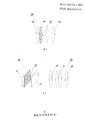
- FIG. 1 is a schematic structural diagram of a 3D video playing device in the prior art.
- FIG. 2 is a schematic structural view of a first embodiment of a 3D display device of the present invention.
- FIG. 3 is a schematic structural view of a second embodiment of a 3D display device of the present invention.
- FIG. 4 is a schematic structural view of a first embodiment of a lens in 3D glasses according to the present invention.
- Figure 5 is a schematic view showing the structure of a second embodiment of the lens in the 3D glasses of the present invention.
- FIG. 6 is a schematic structural diagram of a first embodiment of a 3D video playback device according to the present invention.
- FIG. 7 is a schematic structural diagram of a second embodiment of a 3D video playback device according to the present invention.
- FIG. 8 is a schematic structural diagram of a third embodiment of a 3D video playback device according to the present invention.
- FIG. 9 is a schematic structural diagram of a fourth embodiment of a 3D video playback device according to the present invention.
- FIG. 2 is a schematic structural view of a first embodiment of a 3D display device 10 of the present invention.
- the 3D display device 10 includes a liquid crystal display 11, a first polarizer 12, and a first quarter-wavelength retardation plate 13.
- a surface of the first polarizer 12 is adjacent to a light-emitting surface of the liquid crystal display 11. Fitted, and the shape and size of the first polarizer 12 are matched with the light-emitting surface of the liquid crystal display 11, the first quarter-wavelength retardation plate 13 is disposed on the other surface of the first polarizer 12, and the first A 1/4 wavelength phase difference plate 13 is also sized and shaped to match the light emitting surface of the liquid crystal display 11.
- the angle between the polarization axis of the first quarter-wavelength retardation plate 13 and the transmission axis of the first polarizer 12 is 45°.
- the 3D display device overcomes the technical defect that the polarization direction of the polarized light emitted by the 3D display device 10 is single.
- FIG. 3 is a schematic structural view of a second embodiment of a 3D display device 10 of the present invention.
- the first embodiment is different from the first embodiment of the 3D display device 10 in that the first 1/2 wavelength phase difference plate 14 is disposed on the first polarized light.
- the sheet 12 is interposed between the first quarter-wavelength retardation plate 13 and the size and shape of the first 1/2 wavelength retardation plate 14 are matched with the light-emitting surface of the liquid crystal display 11.
- the angle between the polarization axis of the first 1/2 wavelength phase difference plate 14 and the transmission axis of the first polarizer 12 is ⁇ 1
- the polarization axis of the first 1/4 wavelength phase difference plate 13 is
- the angle between the transmission axes of the first polarizer 12 is 2 ⁇ 1 +45°.
- the retardation value of the light is inversely proportional to the wavelength
- the retardation value of the short wavelength is larger than the retardation value of the long wavelength
- the incident linearly polarized light passes through the first quarter-wavelength phase.
- the difference plate 13 After the difference plate 13, it will become a circular deviation, but the retardation values of the wavelengths of 450 nm and 650 nm are different from 550 nm, and are generally called retardation. Therefore, after passing through the first quarter-wavelength retardation plate 13, it does not become a positive circular deviation, so that a first 1/2 wavelength retardation plate 14 is added to improve the first quarter-wavelength retardation plate 13 The resulting dispersion problem.
- the second 1/2 wavelength phase difference plate 24 mentioned below has the same principle and function.
- the invention also relates to a lens 20 in 3D glasses.
- a lens 20 in 3D glasses Referring to Figure 4, there is shown a block diagram of a first embodiment of a lens 20 in a 3D glasses of the present invention.
- the 3D glasses are used in combination with the 3D display device 10, and the 3D glasses include two left and right symmetrical lenses 20, and the lens 20 includes a second quarter-wavelength phase difference plate 22, a liquid crystal layer 21, and a second polarized light.
- the sheet 23, the second quarter-wavelength phase difference plate 22 and the second polarizer 23 are respectively located on both sides of the liquid crystal layer 21, wherein the size and shape of the second quarter-wavelength phase difference plate 22 and the second polarizer 23 are Both match the liquid crystal layer 21.
- one side of the second quarter-wavelength retardation plate 22 faces the light-emitting surface of the 3D display device 10, and the light emitted by the 3D display device 10 passes through the first polarizing plate 12.
- the circularly polarized light is firstly transmitted through the second quarter-wavelength phase difference plate 22 of the lens 20 when entering the 3D glasses, and the second quarter-wavelength phase difference plate 22 reduces the circularly polarized light to linearly polarized light, and then enters the liquid crystal.
- the layer 21 transmits the second polarizing film 23 and finally enters the human eye to form an image.
- the angle between the polarization axis of the second quarter-wavelength retardation plate 22 and the absorption axis of the second polarizer 23 is -45.
- the angle of the optical rotation is controlled by controlling the torsion angle of the liquid crystal in the liquid crystal layer 21, and the second polarizer 23 can serve as a technical effect of the shutter.
- light can be transmitted in the form of circularly polarized light from the 3D display device 10 to the 3D glasses, which overcomes the decrease in image brightness caused by the improper angle between the 3D glasses and the 3D display device 10. It is a technical defect that does not produce images.
- FIG. 5 is a schematic structural view of a second embodiment of a lens in 3D glasses according to the present invention.
- This embodiment is different from the first embodiment of the lens 20 in the above 3D glasses in that it further includes a second 1/2 wavelength phase difference plate 24, and the second 1/2 wavelength phase difference plate 24 is disposed on the second 1
- the /4 wavelength retardation plate 11 is interposed between the liquid crystal layer 21, and the size and shape of the second 1/2 wavelength retardation plate 24 are matched with the liquid crystal layer 21.
- the polarization axis of the second 1/2 wavelength phase difference plate 24 and the polarization axis of the second polarizer 23 is - ⁇ 2
- the polarization axis of the second 1/4 wavelength phase difference plate 22 is The angle between the polarization axes of the second polarizer 23 is -2 ⁇ 2 - 45°.
- the added second 1/2 wavelength phase difference plate 24 can improve the dispersion problem caused by the second quarter-wavelength phase difference plate 22.
- FIG. 6 is a schematic structural diagram of a first embodiment of a 3D video playing device according to the present invention.
- the 3D display device 10 and the 3D glasses are included, wherein the 3D display device 10 includes a liquid crystal display 11, a first polarizer 12, and a first quarter-wavelength retardation plate 13, the first polarizer 12
- the first polarizer 12 One surface of the liquid crystal display 11 is bonded to the light-emitting surface of the liquid crystal display 11, and the shape and size of the first polarizer 12 are matched with the light-emitting surface of the liquid crystal display 11.
- the first quarter-wavelength retardation plate 13 is disposed on the first surface.
- the other surface of a polarizer 12, and the size and shape of the first quarter-wavelength retardation plate 13 also matches the light-emitting surface of the liquid crystal display 11.
- the angle between the polarization axis of the first quarter-wavelength retardation plate 13 and the transmission axis of the first polarizer 12 is 45°.
- the 3D glasses are used in combination with the above-mentioned 3D display device 10.
- the 3D glasses include left and right symmetrical lenses 20, and the lens 20 includes a second quarter-wavelength phase difference plate 22, a liquid crystal layer 21 and a second polarizer 23, and the second 1/1
- the four-wavelength phase difference plate 22 and the second polarizer 23 are respectively located on both sides of the liquid crystal layer 21, wherein the size and shape of the second quarter-wavelength phase difference plate 22 and the second polarizer 23 are matched with the liquid crystal layer 21. .
- the 3D glasses are located on the light-emitting surface side of the 3D display device 10 and located in the optical path of the 3D display device 10, and the second quarter-wavelength phase difference plate 22 of the 3D glasses faces the light-emitting surface of the 3D display device 10.
- the angle between the polarization axis of the second quarter-wavelength retardation plate 22 and the absorption axis of the second polarizer 23 is -45.
- the second quarter-wavelength retardation plate 22 When used in conjunction with the 3D video playback device, one side of the second quarter-wavelength retardation plate 22 faces the light-emitting surface of the 3D display device 10, and the light emitted by the 3D display device 10 passes through the first polarizing plate 12. After being converted into linearly polarized light, it is converted into circularly polarized light by the first quarter-wavelength retardation plate 13. The circularly polarized light is firstly transmitted through the second quarter-wavelength phase difference plate 22 of the lens 20 when entering the 3D glasses, and the second quarter-wavelength phase difference plate 22 reduces the circularly polarized light to linearly polarized light, and then enters the liquid crystal.
- the layer 21 After the layer 21 is optically rotated, it is transmitted through the second polarizing plate 23, and finally enters the human eye to form an image.
- the angle of the optical rotation is controlled by controlling the torsion angle of the liquid crystal in the liquid crystal layer 21, and the technical effect of the shutter can be achieved by the second polarizer 23.
- the 3D playback device causes light to propagate in the form of circularly polarized light from the 3D display device 10 to the 3D glasses, overcoming the problem that the angle between the 3D glasses and the 3D display device 10 is inappropriate.
- the degradation of image brightness is even a technical defect that does not produce images.
- FIG. 7 is a schematic structural diagram of a second embodiment of a 3D video playing device according to the present invention.
- This embodiment is different from the first embodiment of the above 3D video playback device in that it further includes a second 1/2 wavelength phase difference plate 24, and the second 1/2 wavelength phase difference plate 24 is disposed on the second 1/second.
- the 4 wavelength retardation plate 11 is interposed between the liquid crystal layer 21, and the size and shape of the second 1/2 wavelength retardation plate 24 are matched with the liquid crystal layer 21.
- the polarization axis of the second 1/4 wavelength retardation plate 24 is - ⁇ 2
- the angle between the absorption axes of the second polarizer 23 is -2 ⁇ 2 - 45°.
- the added second 1/2 wavelength phase difference plate 24 can improve the dispersion problem caused by the second quarter-wavelength phase difference plate 22.
- FIG. 8 is a schematic structural diagram of a third embodiment of a 3D video playing device according to the present invention.
- the first embodiment is different from the first embodiment of the 3D video playback device in that the first 1/2 wavelength phase difference plate 14 is disposed on the first polarization.
- the sheet 12 is interposed between the first quarter-wavelength retardation plate 13 and the size and shape of the first 1/2 wavelength retardation plate 14 are matched with the light-emitting surface of the liquid crystal display 11.
- the angle between the polarization axis of the first 1/2 wavelength phase difference plate 14 and the transmission axis of the first polarizer 12 is ⁇ 1
- the polarization axis of the first 1/4 wavelength phase difference plate 13 is
- the angle between the transmission axes of the first polarizer 12 is 2 ⁇ 1 +45°.
- the added first 1/2 wavelength phase difference plate 14 can improve the dispersion problem caused by the first 1/4 wavelength phase difference plate 13.
- FIG. 9 is a schematic structural diagram of a fourth embodiment of a 3D video playing device according to the present invention.
- This embodiment is different from the first embodiment of the above 3D video playback device in that it further includes a first 1/2 wavelength phase difference plate 14 and a second 1/2 wavelength phase difference plate 24, the first 1/2
- the wavelength retardation plate 14 is disposed between the first polarizer 12 and the first 1/4 wavelength retardation plate 13, and the size and shape of the first 1/2 wavelength retardation plate 14 are the same as the liquid crystal display 11 described above.
- the illuminating surfaces match.
- the angle between the polarization axis of the first 1/2 wavelength phase difference plate 14 and the transmission axis of the first polarizer 12 is ⁇ 1
- the polarization axis of the first 1/4 wavelength phase difference plate 13 is The angle between the transmission axes of the first polarizer 12 is 2 ⁇ 1 +45°.
- the second 1/2 wavelength phase difference plate 24 is disposed between the second 1/4 wavelength phase difference plate 22 and the liquid crystal layer 21, and the size and shape of the second 1/2 wavelength phase difference plate 24 are as described above.
- the liquid crystal layers 21 are matched.
- the angle between the polarization axis of the second 1/2 wavelength retardation plate 24 and the absorption axis of the second polarizer 23 is - ⁇ 2
- the polarization axis of the second 1/4 wavelength phase difference plate 22 is The angle between the absorption axes of the second polarizer 23 is -2 ⁇ 2 - 45°.
- the added first 1/2 wavelength phase difference plate 14 can improve the dispersion problem caused by the first 1/4 wavelength phase difference plate 13.
- the added second 1/2 wavelength phase difference plate 24 can improve the dispersion problem caused by the second quarter-wavelength phase difference plate 22.
- a 1/4 wavelength phase difference plate (including the first quarter wavelength phase difference plate 13 and the second 1/1) is added to the liquid crystal display 11 end and the lens 20 end of the 3D glasses.
- the 4-wavelength phase difference plate 22 causes light to propagate in the form of circularly polarized light from the 3D display device 10 to the 3D glasses, overcoming the problem that the angle between the 3D glasses and the 3D display device 10 is not suitable.
- the degradation of image brightness is even a technical defect that does not produce images.
- a 1/2 wavelength phase difference plate (including a first 1/2 wavelength phase difference plate 14 and a second 1/2 wavelength phase difference plate 24) is added to the lens 20 end of the 3D display device 10 and/or the 3D glasses, and The problem of dispersion caused by the above 1/4 wavelength phase difference plate is effectively solved.
Landscapes
- Physics & Mathematics (AREA)
- Nonlinear Science (AREA)
- General Physics & Mathematics (AREA)
- Optics & Photonics (AREA)
- Mathematical Physics (AREA)
- Chemical & Material Sciences (AREA)
- Crystallography & Structural Chemistry (AREA)
- Liquid Crystal (AREA)
Abstract
一种3D眼镜和3D视频播放设备,在液晶显示器(11)端和3D眼镜端各加入了一块1/4波长相位差板(13),使得光在从3D显示装置到3D眼镜之间是以圆偏振光的形式进行传播,克服了因3D眼镜与3D显示装置之间的角度不合适时而产生的影像亮度下降甚至是不产生影像的技术缺陷。
Description
技术领域
本发明涉及显示技术领域,尤其涉及一种3D眼镜和3D视频播放设备。
背景技术
随着科技的不断进步与发展,3D视频逐渐进入人们的视野,观看时犹如身临其境及对视觉的冲击使其得到广大消费者的喜爱。目前市场上最常见的实现3D效果的装置是一种光闸式眼镜,该眼镜的两镜片上分别安装了光闸,两个光闸一个打开,一个关闭相互交替,这样就可以实现一只眼睛只看一张影像,由于影像在人眼中能保持约0.15s的视觉停留,只要同一镜片再次打开的时间间隔小于0.15s,眼睛中的影像就不会消失。这样虽然这只眼睛没有看到影像,但大脑中仍有影像停留,如此便会在大脑中合成3D图像。
参照图1,图1为现有技术中3D视频播放设备的一实施例的结构示意图,现有的技术常采用在显示器1设置第一偏光片3,相配套的3D眼镜包括第二偏光片4、液晶层2和第三偏光片5,其中液晶层2位于第二偏光片4与第三偏光片5之间,第一偏光片3的穿透轴与第二偏光片4的穿透轴平行,第三偏光片5的穿透轴与第二偏光片4的穿透轴垂直,通过控制液晶层2中液晶的扭转,便可以起到光闸的作用,使用者将会在3D眼镜远离显示器1的一侧观察到3D影像。但是该3D眼睛是佩戴在使用者的头部,当第二偏光片4的穿透轴与显示器1设置的第一偏光片3的穿透轴之间不再平行时,影像的亮度便会变暗,当第二偏光片4的穿透轴与显示器端设置的第一偏光片3的穿透轴相互垂直时,此时从显示器1出来的光,会被第二偏光片4完全吸收,使用者将无法看到任何影像。
发明内容
本发明的主要目的是提供一种3D眼镜和3D视频播放设备,旨在解决因3D显示装置与3D眼镜之间的角度倾斜所产生的影像亮度下降甚至是不产生影像的技术缺陷。
本发明提供的一种3D眼镜,所述3D眼镜包括左右两对称的镜片,所述镜片包括液晶层以及分别位于所述液晶层两侧的第二1/4波长相位差板和第二偏光片,其中,所述第二1/4波长相位差板和第二偏光片均与所述液晶层匹配。
优选地,所述3D眼镜还包括第二1/2波长相位差板,所述第二1/2波长相位差板设置于所述第二1/4波长相位差板与所述液晶层之间,且与所述液晶层匹配。
优选地,当所述第二1/2波长相位差板的偏光轴与所述第二偏光片的吸收轴之间夹角为-θ2时,所述第二1/4波长相位差板的偏光轴与所述第二偏光片的吸收轴之间夹角为-2θ2-45°。
本发明还提供一种3D视频播放设备,包括3D显示装置和如上所述的3D眼镜,其中,所述3D显示装置包括液晶显示器、第一偏光片和第一1/4波长相位差板,所述第一偏光片的一表面与所述液晶显示器的出光面相贴合,且所述第一偏光片与所述液晶显示器的出光面匹配,所述第一1/4波长相位差板设置于第一偏光片的另一表面,且所述第一1/4波长相位差板与所述液晶显示器的出光面匹配;
所述3D眼镜位于所述3D显示装置的出光面一侧并在所述3D显示装置的光路中,且所述3D眼镜的第二1/4波长相位差板朝向所述3D显示装置的出光面。
优选地,所述3D显示装置还包括第一1/2波长相位差板,所述第一1/2波长相位差板设置于所述第一偏光片与所述第一1/4波长相位差板之间,且与所述液晶显示器的出光面匹配。
优选地,所述3D眼镜还包括第二1/2波长相位差板,所述第二1/2波长相位差板设置于所述第二1/4波长相位差板与所述液晶层之间,且与所述液晶层匹配。
优选地,当所述第一1/2波长相位差板的偏光轴与所述第一偏光片的穿透轴之间夹角为θ1时,所述第一1/4波长相位差板的偏光轴与所述第一偏光片的穿透轴之间夹角为2θ1+45°;
当所述第二1/2波长相位差板的偏光轴与所述第二偏光片的吸收轴之间夹角为-θ2°时,所述第二1/4波长相位差板的偏光轴与所述第二偏光片的吸收轴之间夹角为-2θ2-45°。
本发明还提供另一种3D视频播放设备,包括3D显示装置和如上所述的3D眼镜,其中,所述3D显示装置包括液晶显示器、第一偏光片、第一1/4波长相位差板和第一1/2波长相位差板,所述第一偏光片的一表面与所述液晶显示器的出光面相贴合,且所述第一偏光片与所述液晶显示器的出光面匹配,所述第一1/4波长相位差板设置于第一偏光片的另一表面,且所述第一1/4波长相位差板与所述液晶显示器的出光面匹配,所述第一1/2波长相位差板设置于所述第一偏光片与所述第一1/4波长相位差板之间,且与所述液晶显示器的出光面匹配;
所述3D眼镜位于所述3D显示装置的出光面一侧并在所述3D显示装置的光路中,且所述3D眼镜的第二1/4波长相位差板朝向所述3D显示装置的出光面;所述3D眼镜还包括第二1/2波长相位差板,所述第二1/2波长相位差板设置于所述第二1/4波长相位差板与所述液晶层之间,且与所述液晶层匹配。
优选地,当所述第一1/2波长相位差板的偏光轴与所述第一偏光片的穿透轴之间夹角为θ1时,所述第一1/4波长相位差板的偏光轴与所述第一偏光片的穿透轴之间夹角为2θ1+45°;
当所述第二1/2波长相位差板的偏光轴与所述第二偏光片的吸收轴之间夹角为-θ2°时,所述第二1/4波长相位差板的偏光轴与所述第二偏光片的吸收轴之间夹角为-2θ2-45°。
本发明3D眼镜和3D视频播放设备,在液晶显示器端和3D眼镜端各加入了一块1/4波长相位差板(包括第一1/4波长相位差板和第二1/4波长相位差板),使得光在从3D显示装置到3D眼镜之间是以圆偏振光的形式进行传播,克服了因3D眼镜与3D显示装置之间的角度不合适时而产生的影像亮度下降甚至是不产生影像的技术缺陷。另外在3D显示装置和/或3D眼镜端加入了1/2波长相位差板(包括第一1/2波长相位差板和第二1/2波长相位差板),可以有效地解决因上述1/4波长相位差板而引起的色散问题。
附图说明
图1为现有技术中3D视频播放设备的结构示意图。
图2为本发明3D显示装置的第一实施例的结构示意图。
图3为本发明3D显示装置的第二实施例的结构示意图。
图4为本发明3D眼镜中镜片的第一实施例的结构示意图。
图5为本发明3D眼镜中镜片的第二实施例的结构示意图。
图6为本发明3D视频播放设备的第一实施例的结构示意图。
图7为本发明3D视频播放设备的第二实施例的结构示意图。
图8为本发明3D视频播放设备的第三实施例的结构示意图。
图9为本发明3D视频播放设备的第四实施例的结构示意图。
本发明目的的实现、功能特点及优点将结合实施例,参照附图做进一步说明。
具体实施方式
下面结合附图及具体实施例就本发明的技术方案做进一步的说明。应当理解,此处所描述的具体实施例仅仅用以解释本发明,并不用于限定本发明。
本发明涉及3D显示装置10。参照图2,图2为本发明3D显示装置10的第一实施例的结构示意图。
在本实施例中,3D显示装置10包括液晶显示器11、第一偏光片12和第一1/4波长相位差板13,该第一偏光片12的一表面与所述液晶显示器11的出光面相贴合,并且该第一偏光片12的形状和大小均与液晶显示器11的出光面相匹配,该第一1/4波长相位差板13设置于第一偏光片12的另一表面,并且该第一1/4波长相位差板13大小和形状也与液晶显示器11的出光面相匹配。上述第一1/4波长相位差板13的偏光轴与所述第一偏光片12的穿透轴之间夹角为45°。液晶显示器11所发出的自然光经第一偏光片12后,被转化为线偏振光,该线偏振光再经第一1/4波长相位差板13后,被转化为圆偏振光。本实施例提供的3D显示装置克服了3D显示装置10所发出的偏振光偏振方向单一的技术缺陷。
参照图3,图3为本发明3D显示装置10的第二实施例的结构示意图。
本实施例与上述3D显示装置10的第一实施例的区别之处在于,还包括第一1/2波长相位差板14,该第一1/2波长相位差板14设置于上述第一偏光片12与上述第一1/4波长相位差板13之间,并且该第一1/2波长相位差板14的大小和形状均与上述液晶显示器11的出光面相匹配。当上述第一1/2波长相位差板14的偏光轴与上述第一偏光片12的穿透轴之间夹角为θ1时,上述第一1/4波长相位差板13的偏光轴与上述第一偏光片12的穿透轴之间夹角为2θ1+45°。在本实施例中,因为光的迟缓值与波长成反比,因此短波长的迟缓值会比长波长迟缓值大,造成波长在nm量级时,入射的线偏光经过第一1/4波长相位差板13后,会变成圆偏,但450nm及650nm波长的迟缓值与550nm不同,一般称为色偏迟缓。因此在经过第一1/4波长相位差板13后,不会变成正圆偏,所以加入一个第一1/2波长相位差板14来改善因第一1/4波长相位差板13而引起的色散问题。下面所提到的第二1/2波长相位差板24其工作原理及作用同理。
本发明还涉及3D眼镜中镜片20。参照图4,图4为本发明3D眼镜中镜片20的第一实施例的结构示意图。
在本实施例中,该3D眼镜与上述3D显示装置10配套使用,3D眼镜包括左右两片对称的镜片20,镜片20包括第二1/4波长相位差板22、液晶层21和第二偏光片23,第二1/4波长相位差板22和第二偏光片23分别位于液晶层21的两侧,其中,第二1/4波长相位差板22和第二偏光片23的大小和形状均与液晶层21相匹配。在与上述3D显示装置10配套使用时,上述第二1/4波长相位差板22的一面应朝向上述3D显示装置10的出光面,上述3D显示装置10所发出的光经第一偏光板12后,被转换成线偏振光后,再经第一1/4波长相位差板13后,被转换成圆偏振光。该圆偏振光在进入3D眼镜时会率先透射镜片20的第二1/4波长相位差板22,第二1/4波长相位差板22将圆偏振光还原为线偏振光后,再进入液晶层21,透射第二偏振片23,最后进入人眼形成影像。上述第二1/4波长相位差板22的偏光轴与上述第二偏光片23的吸收轴之间夹角为-45°。
本实施例通过控制液晶层21中的液晶的扭转角度来控制旋光的角度,配合第二偏光片23可起到光闸的技术效果。本实施例可以使光在从3D显示装置10到3D眼镜之间是以圆偏振光的形式进行传播,克服了因3D眼镜与3D显示装置10之间的角度不合适时而产生的影像亮度下降甚至是不产生影像的技术缺陷。
参照图5,图5为本发明3D眼镜中镜片的第二实施例的结构示意图。
本实施例与上述3D眼镜中镜片20的第一实施例的区别之处在于,还包括第二1/2波长相位差板24,第二1/2波长相位差板24设置于上述第二1/4波长相位差板11与上述液晶层21之间,并且该第二1/2波长相位差板24的大小与形状与上述液晶层21相匹配。当上述第二1/2波长相位差板24的偏光轴与上述第二偏光片23的偏光轴之间夹角为-θ2时,上述第二1/4波长相位差板22的偏光轴与上述第二偏光片23的偏光轴之间夹角为-2θ2-45°。
所加入的第二1/2波长相位差板24可改善因第二1/4波长相位差板22而引起的色散问题。
本发明还涉及3D视频播放设备。参照图6,图6为本发明3D视频播放设备的第一实施例的结构示意图。
在本实施例中,包括3D显示装置10和3D眼镜,其中,该3D显示装置10包括液晶显示器11、第一偏光片12和第一1/4波长相位差板13,该第一偏光片12的一表面与所述液晶显示器11的出光面相贴合,并且该第一偏光片12的形状和大小均与液晶显示器11的出光面相匹配,该第一1/4波长相位差板13设置于第一偏光片12的另一表面,并且该第一1/4波长相位差板13大小和形状也与液晶显示器11的出光面相匹配。上述第一1/4波长相位差板13的偏光轴与所述第一偏光片12的穿透轴之间夹角为45°。该3D眼镜与上述3D显示装置10配套使用,3D眼镜包括左右两对称的镜片20,镜片20包括第二1/4波长相位差板22、液晶层21和第二偏光片23,第二1/4波长相位差板22和第二偏光片23分别位于液晶层21的两侧,其中,第二1/4波长相位差板22和第二偏光片23的大小和形状均与液晶层21相匹配。并且,3D眼镜位于3D显示装置10的出光面一侧并位于3D显示装置10的光路当中,且3D眼镜的第二1/4波长相位差板22朝向所述3D显示装置10的出光面。上述第二1/4波长相位差板22的偏光轴与上述第二偏光片23的吸收轴之间夹角为-45°。
在与上述3D视频播放设备使用时,上述第二1/4波长相位差板22的一面应朝向上述3D显示装置10的出光面,上述3D显示装置10所发出的光经第一偏光板12后,被转换成线偏振光后,再经第一1/4波长相位差板13后,被转换成圆偏振光。该圆偏振光在进入3D眼镜时会率先透射镜片20的第二1/4波长相位差板22,第二1/4波长相位差板22将圆偏振光还原为线偏振光后,再进入液晶层21经旋光后,透射第二偏振片23,最后进入人眼形成影像。通过控制液晶层21中的液晶的扭转角度来控制旋光的角度,配合第二偏光片23可实现光闸的技术效果。
本实施例提供的3D播放设备使光在从3D显示装置10到3D眼镜之间是以圆偏振光的形式进行传播,克服了因3D眼镜与3D显示装置10之间的角度不合适时而产生的影像亮度下降甚至是不产生影像的技术缺陷。
参照图7,图7为本发明3D视频播放设备的第二实施例的结构示意图。
本实施例与上述3D视频播放设备的第一实施例的区别之处在于,还包括第二1/2波长相位差板24,第二1/2波长相位差板24设置于上述第二1/4波长相位差板11与上述液晶层21之间,并且该第二1/2波长相位差板24的大小与形状与上述液晶层21相匹配。当上述第二1/2波长相位差板24的偏光轴与上述第二偏光片23的吸收轴之间夹角为-θ2时,上述第二1/4波长相位差板22的偏光轴与上述第二偏光片23的吸收轴之间夹角为-2θ2-45°。所加入的第二1/2波长相位差板24可改善因第二1/4波长相位差板22而引起的色散问题。
参照图8,图8为本发明3D视频播放设备的第三实施例的结构示意图。
本实施例与上述3D视频播放设备的第一实施例的区别之处在于,还包括第一1/2波长相位差板14,该第一1/2波长相位差板14设置于上述第一偏光片12与上述第一1/4波长相位差板13之间,并且该第一1/2波长相位差板14的大小和形状均与上述液晶显示器11的出光面相匹配。当上述第一1/2波长相位差板14的偏光轴与上述第一偏光片12的穿透轴之间夹角为θ1时,上述第一1/4波长相位差板13的偏光轴与上述第一偏光片12的穿透轴之间夹角为2θ1+45°。所加入的第一1/2波长相位差板14可改善因第一1/4波长相位差板13而引起的色散问题。
参照图9,图9为本发明3D视频播放设备的第四实施例的结构示意图。
本实施例与上述3D视频播放设备的第一实施例的区别之处在于,还包括第一1/2波长相位差板14和第二1/2波长相位差板24,该第一1/2波长相位差板14设置于上述第一偏光片12与上述第一1/4波长相位差板13之间,并且该第一1/2波长相位差板14的大小和形状均与上述液晶显示器11的出光面相匹配。当上述第一1/2波长相位差板14的偏光轴与上述第一偏光片12的穿透轴之间夹角为θ1时,上述第一1/4波长相位差板13的偏光轴与上述第一偏光片12的穿透轴之间夹角为2θ1+45°。该第二1/2波长相位差板24设置于上述第二1/4波长相位差板22与上述液晶层21之间,并且该第二1/2波长相位差板24的大小与形状与上述液晶层21相匹配。当上述第二1/2波长相位差板24的偏光轴与上述第二偏光片23的吸收轴之间夹角为-θ2时,上述第二1/4波长相位差板22的偏光轴与上述第二偏光片23的吸收轴之间夹角为-2θ2-45°。所加入的第一1/2波长相位差板14可改善因第一1/4波长相位差板13而引起的色散问题。所加入的第二1/2波长相位差板24可改善因第二1/4波长相位差板22而引起的色散问题。
本发明3D眼镜和3D视频播放设备,在液晶显示器11端和3D眼镜的镜片20端各加入了一块1/4波长相位差板(包括第一1/4波长相位差板13和第二1/4波长相位差板22),使得光在从3D显示装置10到3D眼镜之间是以圆偏振光的形式进行传播,克服了因3D眼镜与3D显示装置10之间的角度不合适时而产生的影像亮度下降甚至是不产生影像的技术缺陷。另外在3D显示装置10和/或3D眼镜的镜片20端加入了1/2波长相位差板(包括第一1/2波长相位差板14和第二1/2波长相位差板24),可以有效地解决因上述1/4波长相位差板而引起的色散问题。
以上所述仅为本发明的优选实施例,并非因此限制本发明的专利范围,凡是利用本发明说明书及附图内容所作的等效结构变换,或直接或间接运用在其他相关的技术领域,均同理包括在本发明的专利保护范围内。
Claims (9)
- 一种3D眼镜,其特征在于,所述3D眼镜包括左右两对称的镜片,所述镜片包括液晶层以及分别位于所述液晶层两侧的第二1/4波长相位差板和第二偏光片,其中,所述第二1/4波长相位差板和第二偏光片均与所述液晶层匹配。
- 根据权利要求1所述的3D眼镜,其特征在于,还包括第二1/2波长相位差板,所述第二1/2波长相位差板设置于所述第二1/4波长相位差板与所述液晶层之间,且与所述液晶层匹配。
- 根据权利要求2所述的3D眼镜,其特征在于,当所述第二1/2波长相位差板的偏光轴与所述第二偏光片的吸收轴之间夹角为-θ2时,所述第二1/4波长相位差板的偏光轴与所述第二偏光片的吸收轴之间夹角为-2θ2-45°。
- 一种3D视频播放设备,其特征在于,包括3D显示装置和权利要求1中所述的3D眼镜,其中,所述3D显示装置包括液晶显示器、第一偏光片和第一1/4波长相位差板,所述第一偏光片的一表面与所述液晶显示器的出光面相贴合,且所述第一偏光片与所述液晶显示器的出光面匹配,所述第一1/4波长相位差板设置于第一偏光片的另一表面,且所述第一1/4波长相位差板与所述液晶显示器的出光面匹配;所述3D眼镜位于所述3D显示装置的出光面一侧并在所述3D显示装置的光路中,且所述3D眼镜的第二1/4波长相位差板朝向所述3D显示装置的出光面。
- 根据权利要求4所述的3D视频播放设备,其特征在于,所述3D显示装置还包括第一1/2波长相位差板,所述第一1/2波长相位差板设置于所述第一偏光片与所述第一1/4波长相位差板之间,且与所述液晶显示器的出光面匹配。
- 根据权利要求4所述的3D视频播放设备,其特征在于,所述3D眼镜还包括第二1/2波长相位差板,所述第二1/2波长相位差板设置于所述第二1/4波长相位差板与所述液晶层之间,且与所述液晶层匹配。
- 根据权利要求6所述的3D视频播放设备,其特征在于,当所述第一1/2波长相位差板的偏光轴与所述第一偏光片的穿透轴之间夹角为θ1时,所述第一1/4波长相位差板的偏光轴与所述第一偏光片的穿透轴之间夹角为2θ1+45°;当所述第二1/2波长相位差板的偏光轴与所述第二偏光片的吸收轴之间夹角为-θ2°时,所述第二1/4波长相位差板的偏光轴与所述第二偏光片的吸收轴之间夹角为-2θ2-45°。
- 一种3D视频播放设备,其特征在于,包括3D显示装置和权利要求1中所述的3D眼镜,其中,所述3D显示装置包括液晶显示器、第一偏光片、第一1/4波长相位差板和第一1/2波长相位差板,所述第一偏光片的一表面与所述液晶显示器的出光面相贴合,且所述第一偏光片与所述液晶显示器的出光面匹配,所述第一1/4波长相位差板设置于第一偏光片的另一表面,且所述第一1/4波长相位差板与所述液晶显示器的出光面匹配,所述第一1/2波长相位差板设置于所述第一偏光片与所述第一1/4波长相位差板之间,且与所述液晶显示器的出光面匹配;所述3D眼镜位于所述3D显示装置的出光面一侧并在所述3D显示装置的光路中,且所述3D眼镜的第二1/4波长相位差板朝向所述3D显示装置的出光面;所述3D眼镜还包括第二1/2波长相位差板,所述第二1/2波长相位差板设置于所述第二1/4波长相位差板与所述液晶层之间,且与所述液晶层匹配。
- 根据权利要求8所述的3D视频播放设备,其特征在于,当所述第一1/2波长相位差板的偏光轴与所述第一偏光片的穿透轴之间夹角为θ1时,所述第一1/4波长相位差板的偏光轴与所述第一偏光片的穿透轴之间夹角为2θ1+45°;当所述第二1/2波长相位差板的偏光轴与所述第二偏光片的吸收轴之间夹角为-θ2°时,所述第二1/4波长相位差板的偏光轴与所述第二偏光片的吸收轴之间夹角为-2θ2-45°。
Priority Applications (1)
| Application Number | Priority Date | Filing Date | Title |
|---|---|---|---|
| US13/377,547 US8625036B2 (en) | 2011-07-26 | 2011-10-12 | 3D glasses and 3D video playing apparatus |
Applications Claiming Priority (2)
| Application Number | Priority Date | Filing Date | Title |
|---|---|---|---|
| CN201120267081.3 | 2011-07-26 | ||
| CN2011202670813U CN202275245U (zh) | 2011-07-26 | 2011-07-26 | 3d显示装置、3d眼镜和3d视频播放设备 |
Publications (1)
| Publication Number | Publication Date |
|---|---|
| WO2013013447A1 true WO2013013447A1 (zh) | 2013-01-31 |
Family
ID=46195591
Family Applications (1)
| Application Number | Title | Priority Date | Filing Date |
|---|---|---|---|
| PCT/CN2011/080699 Ceased WO2013013447A1 (zh) | 2011-07-26 | 2011-10-12 | 3d眼镜和3d视频播放设备 |
Country Status (2)
| Country | Link |
|---|---|
| CN (1) | CN202275245U (zh) |
| WO (1) | WO2013013447A1 (zh) |
Families Citing this family (1)
| Publication number | Priority date | Publication date | Assignee | Title |
|---|---|---|---|---|
| CN112394565B (zh) * | 2020-11-05 | 2023-07-25 | 惠州市华星光电技术有限公司 | 显示装置及显示系统 |
Citations (6)
| Publication number | Priority date | Publication date | Assignee | Title |
|---|---|---|---|---|
| US6222672B1 (en) * | 1997-11-26 | 2001-04-24 | Sharp Kabushiki Kaisha | Imaging systems |
| CN201689216U (zh) * | 2010-06-10 | 2010-12-29 | 华映视讯(吴江)有限公司 | 三维影像显示系统及其所采用的显示设备与光阀眼镜 |
| CN101943824A (zh) * | 2010-08-06 | 2011-01-12 | 信利半导体有限公司 | 一种新型液晶3d眼镜及通用型3d眼镜显示系统 |
| CN201796191U (zh) * | 2010-08-20 | 2011-04-13 | 天马微电子股份有限公司 | 立体显示系统 |
| CN102036086A (zh) * | 2009-09-30 | 2011-04-27 | 索尼公司 | 图像显示观看系统、光调制器及图像显示设备 |
| CN102087419A (zh) * | 2009-12-04 | 2011-06-08 | Tcl集团股份有限公司 | 一种三维立体显示系统及方法 |
-
2011
- 2011-07-26 CN CN2011202670813U patent/CN202275245U/zh not_active Expired - Lifetime
- 2011-10-12 WO PCT/CN2011/080699 patent/WO2013013447A1/zh not_active Ceased
Patent Citations (6)
| Publication number | Priority date | Publication date | Assignee | Title |
|---|---|---|---|---|
| US6222672B1 (en) * | 1997-11-26 | 2001-04-24 | Sharp Kabushiki Kaisha | Imaging systems |
| CN102036086A (zh) * | 2009-09-30 | 2011-04-27 | 索尼公司 | 图像显示观看系统、光调制器及图像显示设备 |
| CN102087419A (zh) * | 2009-12-04 | 2011-06-08 | Tcl集团股份有限公司 | 一种三维立体显示系统及方法 |
| CN201689216U (zh) * | 2010-06-10 | 2010-12-29 | 华映视讯(吴江)有限公司 | 三维影像显示系统及其所采用的显示设备与光阀眼镜 |
| CN101943824A (zh) * | 2010-08-06 | 2011-01-12 | 信利半导体有限公司 | 一种新型液晶3d眼镜及通用型3d眼镜显示系统 |
| CN201796191U (zh) * | 2010-08-20 | 2011-04-13 | 天马微电子股份有限公司 | 立体显示系统 |
Also Published As
| Publication number | Publication date |
|---|---|
| CN202275245U (zh) | 2012-06-13 |
Similar Documents
| Publication | Publication Date | Title |
|---|---|---|
| US7436476B2 (en) | High durability and high performance polarization optics using a low-elasticity organic layer | |
| US7518662B2 (en) | Contrast enhancement for liquid crystal based projection systems | |
| CN100538476C (zh) | 多层光学补偿薄膜 | |
| TWI444660B (zh) | 2d/3d切換型立體顯示器及其控制方法 | |
| CN201615988U (zh) | 单液晶光阀单投影机立体投影装置 | |
| US20070297052A1 (en) | Cube wire-grid polarizing beam splitter | |
| WO2019205995A1 (zh) | 显示设备、光学系统和虚拟现实头戴显示设备 | |
| WO2011068342A2 (ko) | 입체 영상 표시 장치 | |
| CN101334559A (zh) | 用于对比度补偿的接近半波延迟器 | |
| US9618765B2 (en) | High power handling polarization switches | |
| JP2011033762A5 (zh) | ||
| WO2015070552A1 (zh) | 液晶镜片以及液晶眼镜 | |
| WO2016182280A1 (ko) | 변조기 비대칭 구동을 이용한 고휘도 입체영상상영장치 및 이를 구동하는 방법 | |
| JP2002148606A5 (zh) | ||
| WO2013013447A1 (zh) | 3d眼镜和3d视频播放设备 | |
| US20070296921A1 (en) | Projection display with a cube wire-grid polarizing beam splitter | |
| CN102540557B (zh) | 立体图像显示器 | |
| JP5833847B2 (ja) | 立体画像表示システム | |
| WO2015143781A1 (zh) | 一种三光路偏振分光立体视频转换系统 | |
| WO2013159379A1 (zh) | 3d显示装置及其相位延迟片 | |
| TWI387315B (zh) | 用來觀看立體影像之快門眼鏡 | |
| CN204964952U (zh) | 显示面板和应用该显示面板的液晶显示器 | |
| WO2014084689A1 (ko) | 표시 장치 | |
| TWI769448B (zh) | 投射立體影像之投影裝置 | |
| WO2013067691A1 (zh) | 3d影像系统及3d眼镜 |
Legal Events
| Date | Code | Title | Description |
|---|---|---|---|
| WWE | Wipo information: entry into national phase |
Ref document number: 13377547 Country of ref document: US |
|
| 121 | Ep: the epo has been informed by wipo that ep was designated in this application |
Ref document number: 11869877 Country of ref document: EP Kind code of ref document: A1 |
|
| NENP | Non-entry into the national phase |
Ref country code: DE |
|
| 122 | Ep: pct application non-entry in european phase |
Ref document number: 11869877 Country of ref document: EP Kind code of ref document: A1 |