WO2013005627A1 - Lever-fitting-type connector - Google Patents
Lever-fitting-type connector Download PDFInfo
- Publication number
- WO2013005627A1 WO2013005627A1 PCT/JP2012/066511 JP2012066511W WO2013005627A1 WO 2013005627 A1 WO2013005627 A1 WO 2013005627A1 JP 2012066511 W JP2012066511 W JP 2012066511W WO 2013005627 A1 WO2013005627 A1 WO 2013005627A1
- Authority
- WO
- WIPO (PCT)
- Prior art keywords
- lever
- male connector
- boss
- fitting
- hood
- Prior art date
Links
Images


Classifications
-
- H—ELECTRICITY
- H01—ELECTRIC ELEMENTS
- H01R—ELECTRICALLY-CONDUCTIVE CONNECTIONS; STRUCTURAL ASSOCIATIONS OF A PLURALITY OF MUTUALLY-INSULATED ELECTRICAL CONNECTING ELEMENTS; COUPLING DEVICES; CURRENT COLLECTORS
- H01R13/00—Details of coupling devices of the kinds covered by groups H01R12/70 or H01R24/00 - H01R33/00
- H01R13/62—Means for facilitating engagement or disengagement of coupling parts or for holding them in engagement
- H01R13/629—Additional means for facilitating engagement or disengagement of coupling parts, e.g. aligning or guiding means, levers, gas pressure electrical locking indicators, manufacturing tolerances
- H01R13/62933—Comprising exclusively pivoting lever
- H01R13/62938—Pivoting lever comprising own camming means
-
- H—ELECTRICITY
- H01—ELECTRIC ELEMENTS
- H01R—ELECTRICALLY-CONDUCTIVE CONNECTIONS; STRUCTURAL ASSOCIATIONS OF A PLURALITY OF MUTUALLY-INSULATED ELECTRICAL CONNECTING ELEMENTS; COUPLING DEVICES; CURRENT COLLECTORS
- H01R13/00—Details of coupling devices of the kinds covered by groups H01R12/70 or H01R24/00 - H01R33/00
- H01R13/62—Means for facilitating engagement or disengagement of coupling parts or for holding them in engagement
- H01R13/629—Additional means for facilitating engagement or disengagement of coupling parts, e.g. aligning or guiding means, levers, gas pressure electrical locking indicators, manufacturing tolerances
- H01R13/62933—Comprising exclusively pivoting lever
Definitions
- the present invention relates to a lever fitting type connector capable of fitting a female connector and a male connector by rotating a lever.
- FIG. 1 shows a related lever fitting connector 100 described in Patent Document 1.
- the lever fitting type connector 100 includes a connector main body 120 having a female connector 110, a male connector 130 as a mating connector to be fitted to the female connector 110, and a lever 140 for fitting the male connector 130 to the female connector 110 by a turning operation. It has.
- the female connector 110 has a female connector housing 112 that accommodates terminals 111, and rotating support shafts 113 project from the left and right outer walls of the female connector housing 112.
- the rotation support shaft 113 is a rotation center of the lever 140.
- a male connector 130 as a mating connector has a male connector housing 131 fitted into the female connector housing 112.
- the male connector housing 131 accommodates a mating terminal 132 connected to the terminal 111 of the female connector housing 112.
- Boss 133 protrudes from the left and right outer walls of the male connector housing 131 so that the boss 133 engages with the lever 140.
- the lever 140 is integrally formed with a pair of left and right arm plates 141 and an operation unit 142 that connects the pair of left and right arm plates 141 on one side.
- Cam grooves 143 into which the bosses 133 of the male connector 130 are inserted are formed in the pair of left and right arm plates 141.
- the pair of left and right arm plates 141 are formed with support holes 144 into which the rotation support shaft 113 of the female connector 110 is inserted.
- Such a lever fitting type connector 100 attaches the lever 140 to the female connector 110 by inserting the rotation support shaft 113 of the female connector 110 into the support hole 144 of the lever 140.
- the male connector 130 is connected to the lever 140 by inserting the boss 133 into the cam groove 143 of the lever 140, and the lever 140 is rotated by operating the operation unit 142. Since the boss 133 moves along the cam groove 143 by the rotation of the lever 140, the male connector housing 131 can be fitted to the female connector housing 112.
- the lever 140 idles when the lever 140 is operated. When such idling occurs, it is necessary to rotate the lever 140 by the amount of idling, and thus unnecessary operating force is required. Further, since the operating area to the lever 140 is reduced by the idle rotation of the lever 140, the operability of the lever 140 is lowered.
- An object of the present invention is to provide a lever fitting connector that can prevent the lever from slipping and reduce the operating force to the lever and can improve the operability to the lever.
- a female connector including a female connector housing in which a terminal of an electric wire terminal is accommodated, and a mating terminal of an electric wire terminal connected to the terminal accommodated in the female connector housing are accommodated.
- a male connector provided with a male connector housing that fits with a female connector and connects a terminal of the electric wire terminal and a mating terminal of the electric wire terminal; and a hood to which the female connector is attached and the male connector is inserted
- the boss pull-in groove has a fitting rotation direction in which the lever pull-in boss fits the male connector into the female connector by inserting the male connector into the hood in the initial rotation position of the lever.
- a lever reversing groove for rotating the lever in the reverse direction, and the lever retracting boss is guided by the rotation operation of the lever in the fitting rotation direction to fit the male connector and the female connector.
- the lever is provided between the retracting groove, the lever reversing groove, and the retracting groove, and is rotated in the fitting rotation direction by the inertial force of the lever after the lever is rotated in the reverse direction.
- the gist of the present invention is a lever fitting type connector provided with a lever inertia rotating part that moves the drawing boss to the drawing groove part.
- the lever retracting boss of the male connector when the male connector is inserted into the hood, the lever retracting boss of the male connector is retracted into the boss retracting groove of the lever, and the lever rotates in the direction opposite to the fitting rotational direction. For this reason, idling (loss rotation) of the lever when operating the lever is reduced, and the lever retracting boss can be pulled into the boss retracting groove at an early stage. Thereby, the insertion force to the hood of the male connector can be reduced, and the operating force of the lever when fitting the male connector to the female connector can be reduced.
- the inner wall of the hood includes a flexible lever temporary locking arm capable of locking the lever at the initial rotation position, and the lever is temporarily locked to the lever temporary locking arm.
- a lever temporary locking holding portion for holding a lever in the initial rotation position, wherein the male connector is inserted into the hood of the male connector in the initial rotation position of the lever;
- a lever temporary locking release protrusion for releasing a temporary locking state with the lever temporary locking holding portion by bending an arm, and inserting the male connector into the hood in the initial rotation state of the lever Accordingly, when the temporary locking state between the lever temporary locking arm and the lever temporary locking holding portion is released, the lever retracting boss may be positioned at the lever inertia rotating portion.
- the temporary locking state between the lever temporary locking arm and the lever temporary locking holding portion is released by inserting the male connector into the hood at the initial rotation position of the lever, and the lever is retracted by this release. Since the boss is located in the lever inertia rotation portion, the lever can be reliably rotated in the fitting rotation direction by inertia.
- the lever is rotated in a state in which a pair of arm plates each having a rotation support shaft projecting from an outer peripheral surface thereof are connected between the pair of arm plates and are rotatably supported by the hood.
- a pair of arm plates provided with the boss pull-in groove on the inner wall side, and the lever reverse groove portion includes a pull-in port into which the lever pull-in boss of the male connector is inserted, and the pull-in
- the lever pull-in boss inserted from the mouth may come into contact, and may include an inclined wall inclined downward along the fitting direction of the male connector to the female connector.
- the lever reversing groove portion is brought into contact with the pull-in port into which the lever pull-in boss of the male connector is inserted, and the lever pull-in boss inserted from the pull-in port, and is along the fitting direction of the male connector to the female connector.
- the lever can be reliably rotated in the direction opposite to the fitting rotation direction.
- the hood may include a lever lock locking portion, and the lever operation portion may include a lever lock that locks the lever lock locking portion when the male connector and the female connector are completely fitted. Good.
- the lever lock latching portion is provided on the hood and the lever lock latching on the lever lock latching portion is provided on the lever, the fitting state of the male connector with the female connector is securely locked. can do.
- FIG. 1 is an exploded perspective view of a related lever fitting connector.
- FIG. 2 is a perspective view showing a lever fitting type connector according to an embodiment of the present invention.
- FIG. 3 is an exploded perspective view showing the lever fitting connector.
- FIG. 4 is a side view showing the lever fitting connector.
- FIG. 5 is a cross-sectional view taken along line AA in FIG.
- FIG. 6 is a front view showing insertion of the male connector into the hood.
- FIG. 7 is a cross-sectional view showing the boss drawing groove.
- FIG. 8 is a cross-sectional view showing a fitting guide portion in one embodiment of the present invention.
- FIG. 9 is an enlarged front view showing the fitting guide portion.
- FIG. 10 is a perspective view showing the guide rib.
- FIG. 11 is a front view showing the guide rib.
- FIG. 12 is a perspective view showing a rib guide groove.
- FIG. 13 is a front view showing a rib guide groove.
- FIG. 14 is a side view for illustrating the formation location of the lever collapse prevention wall.
- 15 is a cross-sectional view taken along line EE in FIG. 16 is a cross-sectional view taken along line FF in FIG.
- FIG. 17 is an enlarged cross-sectional view of a portion J in FIG. 18 is a cross-sectional view taken along the line GG in FIG.
- FIG. 19 is a cross-sectional view showing the reverse rotation preventing portion.
- FIG. 20 is a side view showing another reverse rotation prevention unit.
- 21A and 21B are a side view and a cross-sectional view showing the initial insertion (operation 1) of the male connector.
- 22A and 22B are a side view and a cross-sectional view showing insertion (operation 2) of the male connector following FIG. 23A and 23B are a side view and a cross-sectional view showing male connector insertion (operation 3) following FIG. 24A, 24 ⁇ / b> B, and 24 ⁇ / b> C are a side view and a cross-sectional view illustrating a state where the temporary locking is released by the insertion of the male connector (operation 4).
- FIGS. 25A and 25B are a side view and a cross-sectional view showing a state in which the lever is rotated by the inertial force (operation 5).
- FIGS. 26A and 26B are a side view and a cross-sectional view showing a turning operation (operation 6) to the lever.
- FIGS. 27A and 27B are a side view and a cross-sectional view showing the state (operation 7) following FIG. 28A and 28B are a side view and a cross-sectional view showing a completed state of the male connector fitting (operation 8).
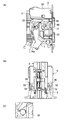
- FIGS. 2 is a perspective view of the lever fitting type connector 1 according to an embodiment of the present invention
- FIG. 3 is an exploded perspective view
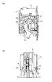
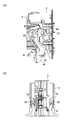
- FIG. 4 is a front view of the hood
- FIG. 5 is a cross-sectional view taken along line AA in FIG.
- FIG. 7 is a sectional view of the boss pull-in groove.
- the lever fitting type connector 1 includes a female connector 2, a male connector 3, a hood 5, and a lever 7.
- the female connector 2 includes a plurality (two) of female connector housings 21 and spacers 22 provided corresponding to the respective female connector housings 21.
- Each female connector housing 21 is formed in a rectangular box shape, and as shown in FIG. 5, a plurality of terminal accommodating chambers 23 are defined therein.
- Each terminal accommodating chamber 23 accommodates a terminal 24 connected to the wire terminal.
- the plurality of connector housings 21 are attached to the hood 5 in an assembled state.
- the male connector 3 includes a plurality (two) of male connector housings 31 and 31a and spacers 32 provided corresponding to the male connector housings 31 and 31a.
- Each male connector housing 31, 31 a is formed in a rectangular box shape like the female connector housing 21.
- Each male connector housing 31, 31 a is formed with a plurality of terminal accommodating chambers 33 corresponding to the terminal accommodating chambers 23 of the female connector housing 21, and each terminal accommodating chamber 33 has terminals of the female connector housing 21.
- the other party terminal 34 connected with 24 is accommodated (refer FIG. 5).
- the plurality of male connector housings 31, 31a are used by being assembled along the height direction.
- the male connector 3 to which the plurality of male connector housings 31 and 31a are assembled is formed with a lever pull-in boss 35, a lever temporary locking release protrusion 36, and a rib guide groove 37 (see FIG. 12).
- the lever retracting boss 35 is engaged with the lever 7, thereby pulling the male connector 3 into the hood 5 by a rotation operation to the lever 7 and fitting the male connector 3 to the female connector 2.
- the lever pull-in boss 35 is formed on the outer surface of the other male connector housing 31 (downward in FIG. 2, right side in FIG. 3).
- the lever retracting boss 35 is formed in a circular shaft shape.
- the lever temporary locking release protrusion 36 is provided so as to protrude from the outer surface of one male connector housing 31a (upward in FIG. 2, left in FIG. 3). Moreover, the lever temporary latch release protrusion 36 is provided so that it may be located in the hood 5 side in the outer surface of the male connector housing 31a. When the male connector 3 is inserted into the hood 5, the lever temporary lock release protrusion 36 releases the temporary lock state between the hood 5 and the lever 7 by bending the lever temporary lock arm 55 of the hood 5 as will be described later. To do. The operations of the lever temporary locking release protrusion 36 and the lever retracting boss 35 will be described later with reference to FIGS.
- the rib guide groove 37 is formed in one male connector housing 31a (upward in FIG. 2, left in FIG. 3).
- the rib guide grooves 37 are provided on both sides of the end portion (upper portion in FIG. 2) of the housing 31a in a state (see FIG. 12) extending along the length direction of the male connector housing 31a that is the fitting direction of the male connector 3. (See FIG. 2).
- the structure and operation of the rib guide groove 37 will be described later with reference to FIG.
- the guide convex part 38 is formed in the top wall part in one male connector housing 31a (refer FIG. 2).
- the guide protrusion 38 guides the fitting of the male connector 3 by sliding the inner surface of the hood 5 when the male connector 3 is fitted to the hood 5.
- the hood 5 is provided with the female connector 2 and the male connector 3 inserted therein.
- the hood 5 includes a collar-shaped plate portion 51, a pair of support wall portions 52, and a connecting cover portion 53.
- the collar plate portion 51 is formed in an oval plate shape, and is located on the opposite side to the side on which the male connector 3 is fitted.
- the female connector 2 is attached to the collar plate 51.
- the collar-shaped plate portion 51 is formed with a mounting opening 51a (see FIG. 5) for mounting the female connector 2.
- the pair of support wall portions 52 project from the one surface side (surface on the male connector 3 side) of the collar-shaped plate portion 51 toward the male connector 3.
- the pair of support wall portions 52 are attached to the lever 7 so as to be rotatable, and support the rotation of the lever 7.
- connection cover 53 connects the pair of support walls 52.
- the connecting cover 53 connects one end of the pair of support walls 52 (the upper end in FIG. 2 and the left end in FIG. 3).
- the connecting cover portion 53 has an arc shape and extends from one surface side (surface on the male connector 3 side) of the collar-shaped plate portion 51 toward the male connector 3 so as to cover the male connector 3 fitted to the hood 5. It has become.
- a lever fall prevention wall 54 is formed on the collar-shaped plate portion 51. As shown in FIGS. 15 to 18, the lever collapse prevention wall 54 is provided so as to project in the same direction as each of the pair of support wall portions 52. The lever collapse prevention wall 54 prevents the lever 7 from falling inward, and the structure and operation thereof will be described later with reference to FIGS.
- the pair of support wall portions 52 are provided with a lever temporary locking arm 55, a lever lock locking portion 56, and a rotation support shaft support hole 57.
- the lever temporary locking arm 55 is temporarily locked to the lever temporary locking holding portion 74 (see FIG. 5) of the lever 7, and is cantilevered from the inner wall of each support wall 52 in the direction of the lever 7. (See FIG. 5), and has a flexible elasticity.
- the lever temporary locking arm 55 locks the lever 7 at the initial rotation position when the male connector 3 is inserted into the hood 5. The operation of the lever temporary locking arm 55 will be described later with reference to FIGS.
- the lever lock locking portions 56 are provided below the respective support wall portions 52 (see FIG. 6), and the levers 7 are locked when the levers 7 are rotated. By this engagement, the rotation of the lever 7 is locked.
- the rotation support shaft support hole 57 supports the rotation of the lever 7 when the rotation support shaft 73 (see FIG. 3) of the lever 7 is rotatably inserted, and the pair of support wall portions 52 have a thickness. It is formed so as to penetrate in the direction.
- a guide rib 58 corresponding to the rib guide groove 37 formed in the male connector 3 is formed in the connecting cover portion 53 of the hood 5. As shown in FIGS. 2 and 10, the guide rib 58 is provided on the fitting side of the male connector 3 in the connection cover portion 53 (inside the connection cover portion 53). Moreover, the guide rib 58 is formed in the connection cover part 53 so that it may extend in the fitting direction of the male connector 3.
- the guide rib 58 and the rib guide groove 37 of the male connector 3 described above constitute a fitting guide portion 9 that guides the male connector 3 to the female connector 2 in a normal fitting direction (see FIG. 8).
- the lever 7 is rotated so as to fit the male connector 3 to the female connector 2.
- the lever 7 is pivotably assembled to the hood 5, and applies a fitting force and a detaching force (selectively) between the male connector 3 and the female connector 2 by a pivoting operation.
- the lever 7 is formed by a pair of left and right arm plates 71 and an operation portion 72 that connects the arm plates 71.
- the pair of arm plates 71 are rotatably supported by the pair of support wall portions 52 of the hood 5, and the rotation support shafts 73 project from the outer surfaces of the arm plates 71.
- the pair of arm plates 71 (that is, the lever 7) is rotatably supported by the pair of support wall portions 52 by inserting the rotation support shaft 73 into the rotation support shaft support holes 57 of the pair of support wall portions 52.
- the pair of arm plates 71 are further provided with a lever temporary locking holding portion 74 and a boss drawing groove 80.
- the lever temporary locking holding portion 74 is to be locked by a lever temporary locking arm 55 formed on the support wall portion 52 of the hood 5, and when the lever temporary locking arm 55 is temporarily locked, the lever 7 is rotated. The initial position is held. This will be described later with reference to FIGS.
- the boss drawing groove 80 is a cam-like groove into which the lever drawing boss 35 (see FIGS. 2 and 3) protruding from the outer surface of the male connector 3 is drawn. As shown in FIG. 3, the boss drawing groove 80 is provided so as to be positioned on the fitting side of the male connector 3 on the inner wall side of the pair of arm plates 71.
- FIG. 7 shows a boss retracting groove 80, which is provided with a lever reversing groove portion 82 and a retracting groove portion 83 continuous with the lever reversing groove portion 82, and has a substantially “ ⁇ ” shape (substantially L-shaped; The shape is slightly opened from the L-shape).
- the lever reversing groove portion 82 has a drawing port 81 opened so that the lever drawing boss 35 is drawn, and an inclined wall 85 continuous to the drawing port 81.
- the pull-in groove 83 is continuous with the lever reversing groove 82 bent upward.
- the pull-in groove 83 is pulled into the lever pull-in boss 35 by rotating the lever 7 in the fitting rotation direction.
- the retracting groove 83 guides the lever retracting boss 35 to fit the male connector 3 to the female connector 2.
- the turning operation of the lever 7 in the fitting turning direction is performed after the lever reverse rotation groove 82 is turned in the direction opposite to the fitting turning direction.
- a lever inertia rotation part 84 is formed between the lever reverse rotation groove part 82 and the drawing groove part 83.
- the lever inertia rotation portion 84 is a portion in which the lever 7 rotates in the fitting rotation direction by the inertia force of the lever itself performed after the lever 7 rotates in the reverse direction in the fitting rotation direction.
- the retracting boss 35 is guided to the retracting groove 83.
- a lever lock 75 is provided on the operation portion 72 of the lever 7 (see FIG. 6).
- the lever lock 75 is provided in the operation portion 72 and corresponds to the lever lock engaging portion 56 of the hood 5. Then, when the lever lock 75 is engaged with the lever lock engaging portion 56, the rotation of the lever 7 is locked, and the fitting state of the male connector 3 to the female connector 2 is locked.
- FIGS. 21A to 28A are diagrams corresponding to FIG. 6, and FIG. 21B is a diagram corresponding to the line AA in FIG.
- FIG. 21 shows the initial insertion of the male connector 3 into the hood 5, and is in a temporarily locked state in which the lever temporary locking holding portion 74 of the lever 7 is held by the lever temporary locking arm 55 of the hood 5.
- the male connector 3 can be pushed out in the opposite direction to the insertion direction by the boss retracting groove 80 formed in a substantially “ ⁇ ” shape.
- the lever retracting boss 35 moves to the end of the lever reverse rotation groove 82 as shown in FIG. 23, and during this movement, the lever 7 is reverse to the fitting rotation direction. It rotates in the (L direction). Even if the lever retracting boss 35 exceeds the substantially “ ⁇ ”-shaped apex of the boss retracting groove 80, the lever 7 remains rotated in the direction opposite to the fitting rotational direction (L direction). During this time, the lever temporary lock holding portion 74 of the lever 7 is in a temporary lock release standby state in which it is gradually separated from the lever temporary lock arm 55 of the hood 5.
- FIG. 24 shows a state in which the male connector 3 is pushed into the hood 5 following this.
- the lever temporary locking release protrusion 36 of the male connector 3 comes into contact with the lever temporary locking arm 55 of the hood 5, and the lever temporary locking arm 55 is moved to the lever temporary locking holding portion 74 of the lever 7. Bend away from Thereby, the temporary locking of the lever 7 is released. By releasing this temporary locking, the lever 7 can be turned.
- the operation area for the lever 7 is an operation area 76a shown in FIG.
- the boss pull-in groove 80 has a substantially “ ⁇ ” shape that allows the lever 7 to rotate in the direction opposite to the fitting rotation direction (L direction). And the lever 7 can be pushed in earlier than the related art.
- the lever retracting boss 35 of the male connector 3 has reached the lever inertia rotating portion 84 in the boss retracting groove 80 (position 35B in FIG. 7). Then, due to the inertial force of the lever itself when the temporary locking of the lever 7 is released, the lever 7 rotates in the fitting rotation direction which is the opposite direction to the arrow L as shown in FIG. At this time, the lever retracting boss 35 is in contact with the boss retracting groove 80 due to the inertial force of the lever itself when the temporary locking of the lever 7 is released.
- FIG. 26 shows a state in which the lever 7 is rotated in the fitting rotation direction from the state of FIG. Since the lever retracting boss 35 reaches the lever inertia rotation portion 84, the lever 7 is rotated in the fitting rotation direction by the inertial force, so that the operation region 76 to the lever 7 is the operation region (inertia in FIG. 24). (Region before rotation in the fitting rotation direction) is larger than 76a. As described above, the lever 7 is rotated before the lever 7 is operated, so that an operation area for the lever 7 is increased. Therefore, the operability to the lever 7 is improved.
- the operating portion 72 of the lever 7 is pressed in the direction of arrow M with the finger 8.
- the lever 7 rotates in the fitting rotation direction around the rotation support shaft 73.
- the lever retracting boss 35 of the male connector 3 is retracted into the retracting groove 83 in the boss retracting groove 80 (position 35C in FIG. 7).
- the lever 7 is further pressed and rotated to the end portion in the fitting rotation direction, whereby the lever lock 75 is engaged with the lever lock engagement portion 56 of the hood 5 and the rotation is stopped.
- the connector 3 is fitted to the female connector 2, and this fitted state is locked.
- the lever retracting boss 35 reaches the terminal end of the retracting groove 83.
- the male connector 3 can be pushed out because the lever retracting boss 35 is not retracted into the boss retracting groove 80 even if the lever 7 is rotated. Thereby, abnormality can be confirmed visually.
- a fitting guide portion 9 is provided for fitting the male connector 3 to the female connector 2 described above (see FIG. 8). As described above, the fitting guide portion 9 is formed by the guide rib 58 and the rib guide groove 37.
- a pair of guide ribs 58 are formed on the inner wall of the connecting cover 53 of the hood 5, and the rib guide grooves 37 are formed on the left and right sides of one male connector housing 31a as shown in FIGS.
- a pair is formed on both side walls.
- the guide rib 58 and the rib guide groove 37 are provided on the opposite side of the operation portion 72 with the rotation support shaft 73 (the rotation support shaft support hole 57) in between, as shown in FIG.
- the guide rib 58 and the rib guide groove 37 extend along the fitting direction of the male connector 3, and the hood guide rib 58 is formed into the rib guide groove when the male connector 3 is fitted to the female connector 2. 37 is inserted.
- the male connector 3 moves in the fitting direction with the guide rib 58 inserted into the rib guide groove 37.
- the guide rib 58 slides relative to the rib guide groove 37. Move. Thereby, the guide rib 58 and the rib guide groove 37 guide the male connector 3 to the female connector 2 in the normal fitting direction.
- the rib guide groove 37 has a cross section formed in a dovetail shape. That is, the rib guide groove 37 is formed in a shape in which the tip portion 37a is wide and the root portion 37b is narrow.
- the guide rib 58 is formed following the cross-sectional shape of the rib guide groove 37 as shown in FIG. Accordingly, the guide rib 58 is inserted into the rib guide groove 37 without being detached from the rib guide groove 37. Accordingly, since the guide rib 58 and the rib guide groove 37 are engaged, the opening of the rib guide groove 37 is prevented, and a force in the pulling direction (force in the direction of arrow D in FIG. 9) acts when the lever 7 is operated. Even if the guide rib 58 does not come off from the rib guide groove 37, the male connector 3 can be stably attached to the hood 5.
- the hood 5 is supported by the male connector 3 and the lever 7 is operated.
- the male connector 3 can be smoothly inserted into the hood 5 without the hood 5 being opened.
- the rib guide groove 37 is formed in the male connector 3 and the guide rib 58 is formed in the hood 5.
- the rib guide groove 37 is formed in the hood 5 and the guide rib 58 is formed in the male connector 3. You may form in.
- the lever collapse prevention wall 54 is formed on the collar-like plate portion 51 of the hood 5 so as to extend in the same direction as the pair of support wall portions 52 of the hood 5.
- FIG. 15 is a cross-sectional view taken along the line EE in FIG. 14
- FIG. 16 is a cross-sectional view taken along the line FF
- FIG. 18 is a cross-sectional view taken along the line GG
- FIG. 15 and 16 on the operation portion 72 side and the lever retracting boss 35 side of the lever 7, the lever collapse prevention wall 54 is substantially parallel to the support wall portion 52 of the hood 5 and is in the collar shape of the hood 5. It stands up directly from the plate part 51.
- the lever collapse prevention wall 54 is located inside the pair of arm plates 71 of the lever 7 and supports the arm plate 71 from the inside.
- the lever collapse prevention wall 54 is formed in a step shape at the tip of the support wall 52 extending from the collar plate 51.
- the support wall 52 further extends from the tip of the support wall 52 in the direction of the wall 52.
- the lever collapse prevention wall 54 is located inside the pair of arm plates 71 in the lever 7 and supports the arm plate 71 from the inside.
- the lever collapse prevention wall 54 supports the plate 71 from the inside at a plurality of locations with respect to the pair of arm plates 71 of the lever 7.
- the lever falling prevention wall 54 supports the pair of arm plates 71 from the inside, whereby the pair of arm plates 71 can be prevented from falling to the inside. Therefore, the arm plate 71 does not fall inward when the lever 7 is rotated, and the male connector 3 can be inserted into the hood 5 with a small force.
- the pair of arm plates 71 are supported by the lever fall prevention wall 54, and the male connector 3 moves in the fitting direction by the rotation of the lever 7 in this state, so that the throat is prevented from being stuck during fitting. Can do.
- lever fall prevention sub-wall 54a in addition to the lever fall prevention wall 54 described above.
- the lever collapse prevention sub-wall 54 a is formed integrally with the pair of support wall portions 52 of the hood 5, and is inserted between the pair of arm plates 71 of the lever 7 and the lever retracting boss 35 of the male connector 3.
- the lever fall prevention sub-wall 54a supports the pair of arm plates 71 of the lever 7 from the outside and functions to prevent the arm plates 71 from falling outside. Accordingly, the lever retracting boss 35 prevents the arm plate 71 from falling inward and outward by the lever falling prevention subwall 54a in addition to the lever falling prevention wall 54.
- the reverse rotation prevention unit 11 prevents the lever 7 from rotating beyond the rotation operation range to the opposite side to the fitting rotation direction.
- the reverse rotation prevention unit 11 is provided in a portion of the hood 5 facing the pair of arm plates 71 of the lever 7. Specifically, with respect to the convex portions 77 formed in a protruding shape on the pair of arm plates 71 of the lever 7, the convex portions projecting in the lever 7 direction on the collar-like plate portion 51 of the hood 5 corresponding to the convex portions 77. Is formed as the reverse rotation preventing portion 11.
- the convex portion 77 of the lever 7 comes into contact with the reverse rotation prevention portion 11 of the hood 5, and the reverse rotation of the lever 7 exceeding the rotation operation range by this contact. Can be prevented.
- the reverse rotation prevention unit 11 is provided in the connecting cover portion 53 of the hood 5.
- the end surface 59 of the connecting cover portion 53 of the hood 5 is opposed to the end surfaces 78 of the pair of arm plates 71 of the lever 7, and the end surface 59 is made thicker than the end surfaces 78 of the arm plate 71. 11.
- the end surface 78 of the lever 7 comes into contact with the reverse rotation preventing portion 11 (end surface 59) of the hood 5, and the lever exceeds the rotation operation range by this contact. 7 inversion can be prevented.
Landscapes
- Details Of Connecting Devices For Male And Female Coupling (AREA)
Abstract
Description
Claims (4)
- 電線端末の端子が収容されたメスコネクタハウジングを備えたメスコネクタと、
前記メスコネクタハウジングに収容された前記端子と接続される電線端末の相手端子が収容され前記メスコネクタと嵌合して前記電線端末の端子と前記電線端末の相手端子とを接続するオスコネクタハウジングを備えたオスコネクタと、
前記メスコネクタが装着されると共に前記オスコネクタが挿入されるフードと、
前記フードに回動自在に組み付けられ、回動動作により前記メスコネクタと前記オスコネクタ間に嵌合力及び離脱力を作用させるレバーと、を備え、
前記オスコネクタは、レバー引き込みボスを備え、
前記レバーは、前記レバーの回動動作により前記レバー引き込みボスが引き込まれるボス引き込み溝を備え、
前記ボス引き込み溝は、
前記レバーの回動初期位置状態での前記オスコネクタの前記フード内への挿入により、前記レバー引き込みボスが、前記オスコネクタを前記メスコネクタに嵌合させる嵌合回動方向と逆方向へ前記レバーを回動させるレバー逆転溝部と、
前記レバーの前記嵌合回動方向への回動動作で前記レバー引き込みボスを案内して、前記オスコネクタと前記メスコネクタとを嵌合させる引き込み溝部と、
前記レバー逆転溝部と前記引き込み溝部との間に設けられ、前記レバーが前記逆方向へ回動した後の前記レバーの慣性力で前記嵌合回動方向へ回動し、前記レバー引き込みボスを前記引き込み溝部へ移動させるレバー慣性回動部と、を備えた
レバー嵌合式コネクタ。 A female connector having a female connector housing in which the terminal of the electric wire terminal is accommodated;
A male connector housing for accommodating a mating terminal of an electric wire terminal connected to the terminal accommodated in the female connector housing and connecting the terminal of the electric wire terminal and the mating terminal of the electric wire terminal by fitting with the female connector. A male connector with
A hood to which the female connector is attached and the male connector is inserted,
A lever that is pivotably assembled to the hood, and that causes a fitting force and a detaching force to act between the female connector and the male connector by a pivoting operation;
The male connector includes a lever retracting boss,
The lever includes a boss pull-in groove into which the lever pull-in boss is pulled by a turning operation of the lever,
The boss lead-in groove is
When the male connector is inserted into the hood when the lever is in the initial rotation position, the lever pull-in boss moves the lever in a direction opposite to the fitting rotation direction in which the male connector is fitted to the female connector. Lever reversing groove for rotating,
A retraction groove for guiding the lever retraction boss in the revolving movement of the lever in the fitting revolving direction and fitting the male connector and the female connector;
Provided between the lever reversing groove portion and the pulling groove portion, the lever is rotated in the fitting rotation direction by the inertial force of the lever after rotating in the reverse direction, and the lever retracting boss is A lever fitting type connector comprising: a lever inertia rotating portion that moves to the drawing groove portion. - 前記フードの内壁は、前記レバーを前記回動初期位置に係止可能な可撓性のレバー仮係止アームを備え、
前記レバーは、前記レバー仮係止アームに仮係止して前記レバーを前記回動初期位置に保持するレバー仮係止保持部を備え、
前記オスコネクタは、前記レバーの前記回動初期位置状態で前記オスコネクタの前記フード内への挿入により前記レバー仮係止アームを撓ませて前記レバー仮係止保持部との仮係止状態を解除するレバー仮係止解除突起を備え、
前記レバーの前記回動初期位置状態で前記オスコネクタの前記フード内への挿入により前記レバー仮係止アームと前記レバー仮係止保持部との前記仮係止状態が解除されると、前記レバー引き込みボスが前記レバー慣性回動部に位置する
請求項1記載のレバー嵌合式コネクタ。 The inner wall of the hood includes a flexible lever temporary locking arm that can lock the lever at the initial rotation position.
The lever includes a lever temporary locking holding portion that temporarily locks the lever temporary locking arm and holds the lever at the initial rotation position.
The male connector is in a temporarily locked state with the lever temporary locking holding portion by bending the lever temporary locking arm by inserting the male connector into the hood in the initial rotation position of the lever. It has a lever temporary lock release protrusion to release,
When the temporary locking state of the lever temporary locking arm and the lever temporary locking holding portion is released by inserting the male connector into the hood in the initial rotation state of the lever, the lever The lever fitting type connector according to claim 1, wherein a pull-in boss is located at the lever inertia rotating portion. - 前記レバーは、
外周面に回動支軸がそれぞれ突設された一対のアームプレートと、
前記一対のアームプレート間を連結すると共に前記フードに回動自在に支持された状態で回動操作を行う操作部と、を備え、
前記一対のアームプレートは、内壁側に前記ボス引き込み溝を備え、
前記レバー逆転溝部は、
前記オスコネクタの前記レバー引き込みボスが挿入される引き込み口と、
前記引き込み口から挿入された前記レバー引き込みボスが当接し、前記オスコネクタの前記メスコネクタへの嵌合方向に沿って下り傾斜の傾斜壁と、を備えた
請求項1又は2記載のレバー嵌合式コネクタ。 The lever is
A pair of arm plates each having a rotation support shaft projecting from the outer peripheral surface;
An operation unit for connecting the pair of arm plates and performing a rotation operation in a state of being rotatably supported by the hood,
The pair of arm plates includes the boss drawing groove on the inner wall side,
The lever reversing groove is
A retraction opening into which the lever retraction boss of the male connector is inserted;
The lever fitting type according to claim 1, further comprising: an inclined wall that comes into contact with the lever drawing boss inserted from the drawing port and that is inclined downward along a fitting direction of the male connector to the female connector. connector. - 前記フードは、レバーロック係止部を備え、
前記レバーの操作部は、前記オスコネクタと前記メスコネクタとの嵌合完了時に前記レバーロック係止部に係止するレバーロックを備えた
請求項3記載のレバー嵌合式コネクタ。 The hood includes a lever lock engaging portion,
The lever fitting type connector according to claim 3, wherein the lever operating portion includes a lever lock that is engaged with the lever lock engaging portion when the male connector and the female connector are completely fitted.
Priority Applications (5)
| Application Number | Priority Date | Filing Date | Title |
|---|---|---|---|
| DE112012002791.4T DE112012002791T5 (en) | 2011-07-01 | 2012-06-28 | lever connector |
| US14/129,561 US9048578B2 (en) | 2011-07-01 | 2012-06-28 | Lever-fitting-type connector |
| KR1020147001475A KR101529264B1 (en) | 2011-07-01 | 2012-06-28 | Leverfittingtype connector |
| CN201280033121.5A CN103636076B (en) | 2011-07-01 | 2012-06-28 | Lever-fitting-type connector |
| IN635CHN2014 IN2014CN00635A (en) | 2011-07-01 | 2012-06-28 |
Applications Claiming Priority (2)
| Application Number | Priority Date | Filing Date | Title |
|---|---|---|---|
| JP2011-147440 | 2011-07-01 | ||
| JP2011147440A JP5723700B2 (en) | 2011-07-01 | 2011-07-01 | Lever fitting type connector |
Publications (1)
| Publication Number | Publication Date |
|---|---|
| WO2013005627A1 true WO2013005627A1 (en) | 2013-01-10 |
Family
ID=47436982
Family Applications (1)
| Application Number | Title | Priority Date | Filing Date |
|---|---|---|---|
| PCT/JP2012/066511 WO2013005627A1 (en) | 2011-07-01 | 2012-06-28 | Lever-fitting-type connector |
Country Status (7)
| Country | Link |
|---|---|
| US (1) | US9048578B2 (en) |
| JP (1) | JP5723700B2 (en) |
| KR (1) | KR101529264B1 (en) |
| CN (1) | CN103636076B (en) |
| DE (1) | DE112012002791T5 (en) |
| IN (1) | IN2014CN00635A (en) |
| WO (1) | WO2013005627A1 (en) |
Families Citing this family (6)
| Publication number | Priority date | Publication date | Assignee | Title |
|---|---|---|---|---|
| JP6605431B2 (en) * | 2016-11-17 | 2019-11-13 | 矢崎総業株式会社 | connector |
| JP6543293B2 (en) * | 2017-03-14 | 2019-07-10 | 矢崎総業株式会社 | Mating connector |
| JP2018195441A (en) * | 2017-05-17 | 2018-12-06 | 矢崎総業株式会社 | Lever fitting type connector |
| JP6794954B2 (en) * | 2017-07-31 | 2020-12-02 | 住友電装株式会社 | connector |
| JP6951664B2 (en) * | 2018-01-25 | 2021-10-20 | 住友電装株式会社 | Lever type connector |
| DE102020105589A1 (en) | 2020-03-03 | 2021-09-09 | Harting Electric Gmbh & Co. Kg | Self-closing locking bracket |
Citations (4)
| Publication number | Priority date | Publication date | Assignee | Title |
|---|---|---|---|---|
| JP2000091026A (en) * | 1998-09-10 | 2000-03-31 | Yazaki Corp | Lever fitting type connector |
| JP2002359037A (en) * | 2001-05-30 | 2002-12-13 | Sumitomo Wiring Syst Ltd | Lever connector |
| JP2009099469A (en) * | 2007-10-18 | 2009-05-07 | Yazaki Corp | Lever-type connector |
| JP2010097954A (en) * | 2010-02-01 | 2010-04-30 | Sumitomo Wiring Syst Ltd | Lever type connector |
Family Cites Families (9)
| Publication number | Priority date | Publication date | Assignee | Title |
|---|---|---|---|---|
| JPH10214635A (en) * | 1997-01-30 | 1998-08-11 | Japan Storage Battery Co Ltd | Lead-acid battery |
| JPH10214653A (en) * | 1997-01-30 | 1998-08-11 | Yazaki Corp | Connector |
| JP3330518B2 (en) * | 1997-07-01 | 2002-09-30 | 矢崎総業株式会社 | Lever mating connector |
| JP3321039B2 (en) * | 1997-08-18 | 2002-09-03 | 矢崎総業株式会社 | Lever mating connector |
| JP3644408B2 (en) * | 2001-05-30 | 2005-04-27 | 住友電装株式会社 | connector |
| JP2003324824A (en) * | 2002-04-26 | 2003-11-14 | Auto Network Gijutsu Kenkyusho:Kk | Ecu converging housing case and wire harness side connector connection structure |
| JP2004311190A (en) * | 2003-04-07 | 2004-11-04 | Sumitomo Wiring Syst Ltd | Lever type connector |
| JP2006344473A (en) * | 2005-06-08 | 2006-12-21 | Sumitomo Wiring Syst Ltd | Lever type connector |
| JP4492449B2 (en) * | 2005-06-15 | 2010-06-30 | 住友電装株式会社 | Lever type connector |
-
2011
- 2011-07-01 JP JP2011147440A patent/JP5723700B2/en active Active
-
2012
- 2012-06-28 KR KR1020147001475A patent/KR101529264B1/en not_active IP Right Cessation
- 2012-06-28 US US14/129,561 patent/US9048578B2/en active Active
- 2012-06-28 DE DE112012002791.4T patent/DE112012002791T5/en not_active Ceased
- 2012-06-28 CN CN201280033121.5A patent/CN103636076B/en active Active
- 2012-06-28 IN IN635CHN2014 patent/IN2014CN00635A/en unknown
- 2012-06-28 WO PCT/JP2012/066511 patent/WO2013005627A1/en active Application Filing
Patent Citations (4)
| Publication number | Priority date | Publication date | Assignee | Title |
|---|---|---|---|---|
| JP2000091026A (en) * | 1998-09-10 | 2000-03-31 | Yazaki Corp | Lever fitting type connector |
| JP2002359037A (en) * | 2001-05-30 | 2002-12-13 | Sumitomo Wiring Syst Ltd | Lever connector |
| JP2009099469A (en) * | 2007-10-18 | 2009-05-07 | Yazaki Corp | Lever-type connector |
| JP2010097954A (en) * | 2010-02-01 | 2010-04-30 | Sumitomo Wiring Syst Ltd | Lever type connector |
Also Published As
| Publication number | Publication date |
|---|---|
| KR101529264B1 (en) | 2015-06-16 |
| JP5723700B2 (en) | 2015-05-27 |
| US20140113476A1 (en) | 2014-04-24 |
| CN103636076B (en) | 2015-12-23 |
| CN103636076A (en) | 2014-03-12 |
| IN2014CN00635A (en) | 2015-04-03 |
| KR20140026618A (en) | 2014-03-05 |
| DE112012002791T5 (en) | 2014-03-13 |
| JP2013016316A (en) | 2013-01-24 |
| US9048578B2 (en) | 2015-06-02 |
Similar Documents
| Publication | Publication Date | Title |
|---|---|---|
| WO2013005629A1 (en) | Lever-fitting-type connector | |
| WO2013005627A1 (en) | Lever-fitting-type connector | |
| JP6424190B2 (en) | Lever type connector | |
| US7931483B2 (en) | Lever-type connector | |
| JP2005317384A (en) | Lever type connector | |
| JP4395784B2 (en) | Lever type connector | |
| JP6492030B2 (en) | connector | |
| WO2013005628A1 (en) | Lever-fitting-type connector | |
| JP2011198517A (en) | Lever-type connector | |
| WO2013132808A1 (en) | Lever-type connector | |
| JP2008103223A (en) | Lever connector | |
| JP2021015720A (en) | Lever-type connector | |
| JP2013110054A (en) | Lever fitting type connector | |
| JP2018041626A (en) | Lever-type connector | |
| JP3495881B2 (en) | connector | |
| JPH1145757A (en) | Releasing structure for slide-type lock lever of connector | |
| JP5872835B2 (en) | Double locking connector | |
| JP2004199990A (en) | Connector | |
| JP2005166575A (en) | Connector | |
| JP7332428B2 (en) | lever type connector | |
| JP6182121B2 (en) | connector | |
| JP2010062077A (en) | Lever fit-in connector | |
| JP2001060479A (en) | Lever-fitting type connector | |
| JP6309737B2 (en) | connector | |
| JP2015220077A (en) | Connector and wire cover |
Legal Events
| Date | Code | Title | Description |
|---|---|---|---|
| 121 | Ep: the epo has been informed by wipo that ep was designated in this application |
Ref document number: 12807501 Country of ref document: EP Kind code of ref document: A1 |
|
| WWE | Wipo information: entry into national phase |
Ref document number: 14129561 Country of ref document: US |
|
| WWE | Wipo information: entry into national phase |
Ref document number: 112012002791 Country of ref document: DE Ref document number: 1120120027914 Country of ref document: DE |
|
| ENP | Entry into the national phase |
Ref document number: 20147001475 Country of ref document: KR Kind code of ref document: A |
|
| 122 | Ep: pct application non-entry in european phase |
Ref document number: 12807501 Country of ref document: EP Kind code of ref document: A1 |