JP2010097954A - Lever type connector - Google Patents

Lever type connector Download PDF

Info

Publication number
JP2010097954A
JP2010097954A JP2010020335A JP2010020335A JP2010097954A JP 2010097954 A JP2010097954 A JP 2010097954A JP 2010020335 A JP2010020335 A JP 2010020335A JP 2010020335 A JP2010020335 A JP 2010020335A JP 2010097954 A JP2010097954 A JP 2010097954A
Authority
JP
Japan
Prior art keywords
lever
housing
housings
locking
fitting
Prior art date
Legal status (The legal status is an assumption and is not a legal conclusion. Google has not performed a legal analysis and makes no representation as to the accuracy of the status listed.)
Granted
Application number
JP2010020335A
Other languages
Japanese (ja)
Other versions
JP5035359B2 (en
Inventor
Yukihiro Fukatsu
幸弘 深津
Riichi Sakurai
利一 櫻井
Masayasu Fujii
雅康 藤井
Current Assignee (The listed assignees may be inaccurate. Google has not performed a legal analysis and makes no representation or warranty as to the accuracy of the list.)
Sumitomo Wiring Systems Ltd
Original Assignee
Sumitomo Wiring Systems Ltd
Priority date (The priority date is an assumption and is not a legal conclusion. Google has not performed a legal analysis and makes no representation as to the accuracy of the date listed.)
Filing date
Publication date
Application filed by Sumitomo Wiring Systems Ltd filed Critical Sumitomo Wiring Systems Ltd
Priority to JP2010020335A priority Critical patent/JP5035359B2/en
Publication of JP2010097954A publication Critical patent/JP2010097954A/en
Application granted granted Critical
Publication of JP5035359B2 publication Critical patent/JP5035359B2/en
Active legal-status Critical Current
Anticipated expiration legal-status Critical

Links

Images

Abstract

<P>PROBLEM TO BE SOLVED: To provide a lever type connector where the posture of one housing can be corrected in the process of fitting two housings. <P>SOLUTION: Immediately before a female housing 10 provided with a lever 12 and a male housing 11 are properly fitted to each other, an operable portion 43 of the lever 12 is located at a lateral end of the female housing 10 and is operated along a fitting direction of the male housing 11. A locking projection 52 is formed in the male housing 11, and an engaging portion 53 which is engageable with the locking projection 52 is formed at an end of the lever 12 opposite to the operable portion 43. Thus, the locking projection 52 and the engaging portion 53 are engaged with each other immediately before the two housings 10, 11 are properly fitted to each other, and the locking projection 52 receive a force acting along the fitting direction of the male housing 11 as the lever 12 is rotated. In this way, the posture of the female housing 10 is corrected, enabling the two housings 10, 11 to be fitted to each other in their proper postures. <P>COPYRIGHT: (C)2010,JPO&INPIT

Description

本発明は、レバー式コネクタに関する。   The present invention relates to a lever-type connector.

従来、レバー式コネクタとしては、特許文献1記載のものが知られている。このものは、雌ハウジングにレバーを回動可能に組付け、このレバーの回動操作により、レバーに形成されたカム溝に沿って、雄ハウジングに形成されたカムピンを誘導することにより、両ハウジングを嵌合させるようになっている。両ハウジングが正規嵌合する直前においては、レバーの操作部は、雌ハウジングの側端部のうち、レバーの回動軸から径方向に離間した側端部の近傍に位置しており、雌ハウジングの嵌合方向に沿う方向に操作されるようになっている。   Conventionally, a lever-type connector described in Patent Document 1 is known. In this structure, a lever is rotatably assembled to the female housing, and both the housings are guided by guiding a cam pin formed on the male housing along a cam groove formed on the lever. Are to be fitted. Immediately before the two housings are properly fitted, the lever operating portion is located in the vicinity of the side end portion of the female housing that is radially spaced from the pivot shaft of the lever. It is operated in a direction along the fitting direction.

特開2001ー326024公報JP 2001-326024 A

しかしながら上記の構成によると、両ハウジングが正規嵌合する直前において、雌ハウジングのうちレバーの操作部の近傍に位置する側端部が、レバーを回動操作することにより雌ハウジングの嵌合方向に沿う方向に押されて、このレバーの操作部近傍の側端部の嵌合状態が、レバーの操作部と反対側に位置する側端部よりも先行してしまい、傾き姿勢となる場合がある。   However, according to the above configuration, immediately before the two housings are properly fitted, the side end portion of the female housing located in the vicinity of the lever operating portion rotates the lever in the fitting direction of the female housing. When pushed in the direction, the fitting state of the side end portion near the operation portion of the lever may precede the side end portion located on the side opposite to the operation portion of the lever, resulting in an inclined posture. .

本発明は上記のような事情に基づいて完成されたものであって、両ハウジングの嵌合過程において一方のハウジングの姿勢を矯正可能なレバー式コネクタを提供することを目的とする。   The present invention has been completed based on the above-described circumstances, and an object thereof is to provide a lever-type connector capable of correcting the posture of one housing in the fitting process of both housings.

上記の目的を達成するための手段として、請求項1の発明は、側板の先端部に操作部を有する1枚板状のレバーが第1ハウジングに回動可能に組み付けられ、前記レバーの回動操作により前記側板に形成されたカム溝に沿って第2ハウジングに形成されたカムピンを誘導することで両ハウジングを嵌合状態とすることができるようになっていると共に、前記両ハウジングが正規嵌合する直前には、前記レバーの操作部は、前記第1ハウジングの側端部のうち、前記レバーの回動軸からこの回動軸の径方向に離間した側端部の近傍に位置して、前記第1ハウジングの嵌合方向に沿う方向に操作されるようになっているレバー式コネクタであって、前記第2ハウジングには係止突部が形成されており、前記レバーのうち前記操作部と反対側の端部には、前記係止突部と係合する係止受け部が形成されており、前記係止突部と前記係止受け部とは、前記両ハウジングが正規嵌合する直前に係合し、前記レバーの回動操作により、前記係止突部は、前記係止受け部を介して前記第2ハウジングの嵌合方向に沿う方向の力を受けるようになっており、前記レバーが、前記第1ハウジングに対して、左右方向に関して対称な2つの姿勢での組み付けを可能とされ、前記係止突部が、前記第2ハウジングに左右で対をなして形成され、前記第1ハウジングには、前記両係止突部と対応する位置に、前記両ハウジングの嵌合方向に沿って延びて、前記両ハウジングの嵌合時に前記両係止突部のそれぞれが摺接する左右1対の案内壁が形成されていることを特徴とする。   As a means for achieving the above object, the invention according to claim 1 is characterized in that a single plate-like lever having an operating portion at the front end portion of the side plate is rotatably assembled to the first housing, and the lever is rotated. The two housings can be brought into a fitted state by guiding a cam pin formed in the second housing along a cam groove formed in the side plate by an operation, and the two housings are properly fitted. Immediately before joining, the operating portion of the lever is located in the vicinity of the side end portion of the side end portion of the first housing that is spaced apart from the turning shaft of the lever in the radial direction of the turning shaft. A lever-type connector adapted to be operated in a direction along the fitting direction of the first housing, wherein a locking projection is formed on the second housing, and the operation of the lever End opposite to the part Is formed with a locking receiving portion that engages with the locking protrusion, and the locking protrusion and the locking receiving portion are engaged immediately before the two housings are properly fitted, By the turning operation of the lever, the locking projection receives a force in the direction along the fitting direction of the second housing via the locking receiving portion, and the lever is Assembling is possible in two postures symmetrical with respect to the left and right direction with respect to the housing, and the locking projections are formed in pairs on the left and right sides of the second housing. A pair of left and right guide walls that extend along the fitting direction of the two housings and that are in sliding contact with each other when the two housings are fitted are formed at positions corresponding to the two locking projections. It is characterized by being.

請求項2の発明は、請求項1記載のものにおいて、前記第1ハウジングはワイヤーハーネスを構成する電線と接続されるハーネス側ハウジングであり、前記第2ハウジングは固定部材に配設される待受け側ハウジングであることを特徴とする。   According to a second aspect of the present invention, in the first aspect, the first housing is a harness side housing connected to an electric wire constituting the wire harness, and the second housing is a standby side disposed on a fixing member. It is a housing.

請求項3の発明は、請求項1または請求項2記載のものにおいて、前記案内壁及び前記係止突部が、それぞれ前記第1ハウジング及び前記第2ハウジングにおける左右方向の対称位置に配置されていることを特徴とする。   According to a third aspect of the present invention, in the first or second aspect of the present invention, the guide wall and the locking protrusion are disposed at symmetrical positions in the left-right direction in the first housing and the second housing, respectively. It is characterized by being.

両ハウジングが正規嵌合する直前において、第1ハウジングのうち、レバーの操作部の近傍に位置する側端部の嵌合状態が、レバーの操作部と反対側に位置する側端部よりも先行している場合に、第2ハウジングの係止突部と、レバーの操作部の反対側に形成した係止受け部とが係合することにより、係止突部が、第2ハウジングの嵌合方向に沿う方向の力を受けることで、第1ハウジングの姿勢が矯正されて、両ハウジングが正規姿勢で嵌合することができる。また、第1ハウジングに形成された案内壁と摺接することで、両ハウジングの嵌合、離脱を案内して、両ハウジングが正規姿勢で嵌合するようになっている。また、レバーの操作スペースに制約がある場合に、レバーの取付け姿勢を自由に選択できるから、両ハウジングの嵌合作業を効率よく行うことができる。   Immediately before the two housings are properly fitted, the fitting state of the side end portion located in the vicinity of the lever operating portion of the first housing precedes the side end portion located on the side opposite to the lever operating portion. The engaging protrusion of the second housing and the engaging receiving portion formed on the opposite side of the lever operating portion are engaged with each other, so that the engaging protrusion is engaged with the second housing. By receiving the force in the direction along the direction, the posture of the first housing is corrected, and both the housings can be fitted in the normal posture. In addition, by sliding contact with a guide wall formed in the first housing, the housing is guided in fitting and detachment, and both housings are fitted in a normal posture. Further, when the lever operating space is limited, the mounting posture of the lever can be freely selected, so that the fitting operation of both housings can be performed efficiently.

実施形態1に係るレバー式コネクタの正規嵌合状態を示す平断面図Plan sectional drawing which shows the regular fitting state of the lever-type connector which concerns on Embodiment 1. FIG. 同じく雄ハウジングと雌ハウジングとを示す側断面図Side sectional view showing male housing and female housing 同じく雄ハウジングの正面図Similarly front view of male housing 同じく雌ハウジングの正面図Similarly front view of female housing 同じく雌ハウジングの平面図A plan view of the female housing 同じくレバーが待受け位置にある状態における雌ハウジングの平断面図と、雄ハウジングの平面図Similarly, a plan view of the female housing and a plan view of the male housing with the lever in the standby position 同じく、両ハウジングの嵌合初期状態を示す、雌ハウジングの平断面図と、雄ハウジングの平面図Similarly, a plan view of a female housing and a plan view of a male housing showing the initial mating state of both housings. 図7よりも嵌合状態が進行した状態を示す、雌ハウジングの平断面図と、雄ハウジングの平面図FIG. 7 is a cross-sectional view of the female housing and a plan view of the male housing, showing a state in which the fitting state has progressed more than FIG. 同じく、両ハウジングが正規嵌合状態にになる直前の状態を示す、雌ハウジングの平断面図と、雄ハウジングの平面図Similarly, a cross-sectional view of the female housing and a plan view of the male housing showing the state immediately before both housings are brought into the normal fitting state. 参考例に係るレバー式コネクタにおいて、レバーが待受け位置にある状態を示す、第1ハウジング及び第2ハウジングの平面図The top view of the 1st housing and the 2nd housing which shows the state which has a lever in a stand-by position in the lever type connector concerning a reference example 同じく、レバー式コネクタの正規嵌合状態を示す平面図Similarly, a plan view showing the normal fitting state of the lever-type connector

<実施形態1>
本発明の実施形態1を図1ないし図9によって説明する。本実施形態に係るレバー式コネクタは、雌ハウジング10(本発明に係る第1ハウジングに相当)と、雄ハウジング11(本発明に係る第2ハウジングに相当)とを、雌ハウジング10に配設したレバー12により嵌合、離脱させるようにしたものである。なお、以下の説明では、両ハウジング10,11の嵌合方向を前方とし、上下方向については、図2を基準とする。
<Embodiment 1>
A first embodiment of the present invention will be described with reference to FIGS. In the lever-type connector according to this embodiment, a female housing 10 (corresponding to a first housing according to the present invention) and a male housing 11 (corresponding to a second housing according to the present invention) are disposed in the female housing 10. The lever 12 is fitted and detached. In the following description, the fitting direction of both housings 10 and 11 is the front, and the vertical direction is based on FIG.

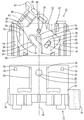
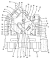
図2及び図3に示すように、雄ハウジング11は合成樹脂材料からなり、図示しない固定部材に配設される待受け側ハウジングとされる。この雄ハウジング11の前側には前方に開口するフード部13が形成されており、このフード部13の後方には、雄端子金具14を収容するための端子収容部15が形成されている。   As shown in FIGS. 2 and 3, the male housing 11 is made of a synthetic resin material, and is a standby side housing disposed on a fixing member (not shown). A hood portion 13 opening forward is formed on the front side of the male housing 11, and a terminal accommodating portion 15 for accommodating the male terminal fitting 14 is formed behind the hood portion 13.

図1における端子収容部15の左右両外側面には、固定部材に雄ハウジング11を取付けるための取付けロック部16が形成されている。図2に示すように、端子収容部15の内部には前後方向に延びるキャビティ17が形成されており、雄端子金具14を後方から収容するようになっている。雄端子金具14は、本体部18と、本体部18の後方に設けられ電線19を圧着するバレル部20とからなり、本体部18の前端には、前方に細長く延びるタブ片21が設けられている。キャビティ17の内壁には前方に片持ち状に延びると共に、撓み変形可能なランス22が突設されており、このランス22は、本体部18と弾性的に係合することにより、雄端子金具14の抜け止めを図るようになっている。雄端子金具14がキャビティ17内に収容された状態では、タブ片21は、フード部13内に突出するようになっている。また、端子収容部15の前端部には、前方からリテーナ23が装着されるようになっており、雄端子金具14を二重係止するようになっている。バレル部20の後方には、防水ゴム栓24が電線19の被覆を一括して囲むように嵌挿されており、この防水ゴム栓24の外周面がキャビティ17の内周面と弾性的に密着することにより、電線19とキャビティ17内面との間がシールされるようになっている。   On the left and right outer surfaces of the terminal accommodating portion 15 in FIG. 1, an attachment lock portion 16 for attaching the male housing 11 to the fixing member is formed. As shown in FIG. 2, a cavity 17 extending in the front-rear direction is formed inside the terminal accommodating portion 15, and the male terminal fitting 14 is accommodated from the rear. The male terminal fitting 14 includes a main body portion 18 and a barrel portion 20 that is provided behind the main body portion 18 and crimps the electric wire 19, and a tab piece 21 that is elongated forward is provided at the front end of the main body portion 18. Yes. On the inner wall of the cavity 17, a lance 22 that cantilevered and extends forward is projected, and the lance 22 is elastically engaged with the main body portion 18, whereby the male terminal fitting 14. It is designed to prevent the slipping out. In a state where the male terminal fitting 14 is accommodated in the cavity 17, the tab piece 21 protrudes into the hood portion 13. A retainer 23 is attached to the front end portion of the terminal accommodating portion 15 from the front, and the male terminal fitting 14 is double-locked. A waterproof rubber plug 24 is fitted and inserted behind the barrel portion 20 so as to collectively surround the coating of the electric wire 19, and the outer peripheral surface of the waterproof rubber plug 24 is elastically in close contact with the inner peripheral surface of the cavity 17. By doing so, the space between the electric wire 19 and the inner surface of the cavity 17 is sealed.

図2及び図3に示すように、フード部13の上壁の外側面には、図3における左右方向の略中央付近であって前端に近い位置に、上方に突出する略円柱状をなすカムピン25が形成されており、後述するレバー12のカム溝26と係合するようになっている。このカムピン25の上端部には、カムピン25の径方向外方に拡径された拡径部27が形成されており、この拡径部27の下端縁と、後述するレバー12のカムピン受け部64とが係合することで、カム溝26とカムピン25とが上下方向に離間するのを防止するようになっている。カムピン25の左右両側には、前後方向に延びる1対の案内リブ28が上方に突設されており、後述する雌ハウジング10の受け部29の側端縁と摺接することにより、両ハウジング10,11の嵌合、離脱を案内するようになっている。この案内リブ28の前端部には、前方に向かって下がり勾配をなすテーパ面30が形成されており、後述するレバー12の仮係止片41が案内リブ28に乗り上げる動作を容易にするようになっている。雄ハウジング11の左右方向の幅寸法の中央を通り、両ハウジング10,11の嵌合方向と平行な仮想直線は、対称軸39となっており、案内リブは、この対称軸39に対して左右対称に配されている。   As shown in FIGS. 2 and 3, the outer surface of the upper wall of the hood 13 has a substantially cylindrical cam pin protruding upward at a position near the front end in the vicinity of the center in the left-right direction in FIG. 25 is formed and engages with a cam groove 26 of the lever 12 described later. An enlarged diameter portion 27 is formed at the upper end portion of the cam pin 25 and is expanded radially outward of the cam pin 25. A lower end edge of the enlarged diameter portion 27 and a cam pin receiving portion 64 of the lever 12 described later. And the cam groove 26 and the cam pin 25 are prevented from separating in the vertical direction. A pair of guide ribs 28 extending in the front-rear direction are provided on the left and right sides of the cam pin 25 so as to project upward. By sliding contact with a side edge of a receiving portion 29 of the female housing 10 to be described later, 11 is adapted to guide the engagement and disengagement. A taper surface 30 is formed at the front end of the guide rib 28 so as to have a downward slope toward the front, so that a temporary locking piece 41 of the lever 12 described later can easily move on the guide rib 28. It has become. An imaginary straight line passing through the center of the width dimension of the male housing 11 in the left-right direction and parallel to the fitting direction of the two housings 10, 11 is a symmetry axis 39. They are arranged symmetrically.

図2及び図4に示すように、雌ハウジング10は、合成樹脂材料からなり、外筒部31の内側には、前後方向に延びる複数のキャビティ17が幅方向に並んで形成された内筒部32が形成されている。各キャビティ17内には、後方から挿入された雌端子金具33が、キャビティ17内に設けられたランス22に係止されて抜け止め状態で収容されるようになっている。雌端子金具33は、略角筒状をなすと共に、雄ハウジング11に収容される雄端子金具14のタブ片21が挿入される角筒部34と、角筒部34の後方に設けられ電線19をかしめつけるバレル部20とからなる。角筒部34内には、弾性変形可能な弾性接触片(図示せず)が形成されており、角筒部34内に挿入されたタブ片21と弾性的に接触するようになっている。また、バレル部20の後方には、防水ゴム栓24が電線19の被覆を一括して囲むように嵌挿されており、この防水ゴム栓24の外周面がキャビティ17の内周面に弾性的に密着することにより、電線19とキャビティ17内面との間がシールされるようになっている。また、内筒部32の前端部には、前方からキャップ状のリテーナ23が、雌ハウジング10に対して冠着されるようになっており、雌端子金具33を二重係止するようになっている。このように雌ハウジング10は、ワイヤーハーネスを構成する電線19と接続されており、ハーネス側ハウジングとされる。   As shown in FIGS. 2 and 4, the female housing 10 is made of a synthetic resin material, and an inner cylinder portion in which a plurality of cavities 17 extending in the front-rear direction are arranged in the width direction inside the outer cylinder portion 31. 32 is formed. In each cavity 17, a female terminal fitting 33 inserted from the rear is received by a lance 22 provided in the cavity 17 so as to be retained in a detached state. The female terminal fitting 33 has a substantially rectangular tube shape and is provided behind the rectangular tube portion 34 into which the tab piece 21 of the male terminal fitting 14 accommodated in the male housing 11 is inserted, and the electric wire 19. And a barrel portion 20 for caulking. An elastic contact piece (not shown) that can be elastically deformed is formed in the rectangular tube portion 34, and is in elastic contact with the tab piece 21 inserted in the rectangular tube portion 34. In addition, a waterproof rubber plug 24 is fitted and inserted behind the barrel portion 20 so as to collectively surround the coating of the electric wire 19, and the outer peripheral surface of the waterproof rubber plug 24 is elastic to the inner peripheral surface of the cavity 17. As a result, the space between the electric wire 19 and the inner surface of the cavity 17 is sealed. A cap-shaped retainer 23 is attached to the female housing 10 from the front at the front end portion of the inner cylindrical portion 32 so that the female terminal fitting 33 is double-locked. ing. As described above, the female housing 10 is connected to the electric wires 19 constituting the wire harness, and is a harness-side housing.

上記の内筒部32と外筒部31との間の隙間には、上述の雄ハウジング11のフード部13が進入するようになっている。内筒部32の前後方向の略中央付近には、内筒部32の外周に、筒状をなすゴム製のシールリング35が装着されている。シールリング35の外周面に、全周に亘って周方向に延びて形成された図示3条のリップ36と、雄ハウジング11のフード部13の内周面とが弾性的に密着することにより、雄ハウジング11と雌ハウジング10との間のシールが図られるようになっている。   The above-described hood portion 13 of the male housing 11 enters the gap between the inner cylinder portion 32 and the outer cylinder portion 31. A rubber seal ring 35 having a cylindrical shape is attached to the outer periphery of the inner cylinder portion 32 in the vicinity of the approximate center in the front-rear direction of the inner cylinder portion 32. With the outer peripheral surface of the seal ring 35, the three lips 36 shown in the figure extending in the circumferential direction and the inner peripheral surface of the hood 13 of the male housing 11 are elastically in close contact with each other, A seal between the male housing 11 and the female housing 10 is achieved.

外筒部31の上側には、前後方向に貫通すると共に、レバー12を収容するためのレバー収容空間37が形成されている。このレバー収容空間37の天井壁からは、下方に垂下して略円柱状をなす支軸38が形成されている。レバー収容空間37は、この支軸38の軸心を通る対称軸39に対して左右対称に形成されている。図6に示すように、外筒部31のうちレバー収容空間37の下壁には、前端縁から後方に向かって略方形に切り欠かれた切欠部40が形成されている。この切欠部40の後端部には、略矩形をなすと共に、切欠部40の左右両側壁から四半円弧上に連なる受け部29が、対称軸39に対して左右対称に内方に突設されている。この受け部29と、後述するレバー12の係止片41とが、後述するレバー12の待受け状態において係合するようになっている。   A lever receiving space 37 for receiving the lever 12 is formed on the upper side of the outer cylindrical portion 31 while penetrating in the front-rear direction. From the ceiling wall of the lever accommodating space 37, a support shaft 38 is formed that hangs downward and has a substantially cylindrical shape. The lever housing space 37 is formed symmetrically with respect to a symmetry axis 39 passing through the axis of the support shaft 38. As shown in FIG. 6, a notch 40 is formed on the lower wall of the lever accommodating space 37 in the outer cylinder portion 31. The notch 40 is cut out in a substantially square shape from the front edge toward the rear. A rear end portion of the notch 40 is formed in a substantially rectangular shape, and a receiving portion 29 that extends from the left and right side walls of the notch 40 on a quadrant is protruded inwardly symmetrically with respect to the symmetry axis 39. ing. The receiving portion 29 and a locking piece 41 of the lever 12 described later are engaged in a standby state of the lever 12 described later.

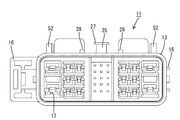
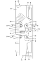
図1に示すように、レバー12は、合成樹脂材料からなり、概ね、上方から見て、円の周縁部のうちの後端部領域を櫛形に切欠した形状をなす側板42と、この側板42の後端部のうち、図1における左端側に、左方へ少し張り出して形成された操作部43とを備えている。レバー12は全体として上下対称な形状となっている。このレバー12は、雌ハウジング10のレバー収容空間37内において、待受け位置と、嵌合位置との間で回動可能に取付けられている。ここで、待受け位置とは、レバー12の側板42に形成されたカム溝26に、雄ハウジング11に形成されたカムピン25が進入するのを許容するレバー12の位置(図6参照)をいい、嵌合位置とは、両ハウジング10,11が正規嵌合した状態におけるレバー12の位置をいう(図1参照)。なお、レバー12の説明における前後左右の向きについては、レバー12が嵌合位置にある状態を基準とする。   As shown in FIG. 1, the lever 12 is made of a synthetic resin material, and includes a side plate 42 having a shape in which a rear end region of a circular peripheral portion is notched in a comb shape when viewed from above, and the side plate 42. 1 is provided with an operation portion 43 formed to protrude slightly to the left on the left end side in FIG. The lever 12 has a vertically symmetrical shape as a whole. The lever 12 is attached to the lever housing space 37 of the female housing 10 so as to be rotatable between a standby position and a fitting position. Here, the standby position refers to the position of the lever 12 that allows the cam pin 25 formed in the male housing 11 to enter the cam groove 26 formed in the side plate 42 of the lever 12 (see FIG. 6). The fitting position refers to the position of the lever 12 in a state where both the housings 10 and 11 are properly fitted (see FIG. 1). Note that the front, rear, left, and right directions in the description of the lever 12 are based on the state where the lever 12 is in the fitting position.

側板42の中心には、軸孔44が上下に貫通して形成されており、上述した支軸38が貫通するようになっている。また、側板42における軸孔44の前方には、軸孔44を中心とする周方向及び径方向の双方に対して斜めをなすカム溝26が形成されている。カム溝26の上端縁には、カムピン25の拡径部27を受けるカムピン受け部64が、カム溝26の全長に亘って形成されている。側板42における軸孔44よりも右方の位置には、レバー12を待受け位置に保持するための係止片41が形成されている。この係止片41は、前後方向に細長い板状をなし、その前端において側板42に対して後方へ片持ち状に延出する形態となっている。この撓み係止片41は、その基端部(前端部)を支点として、上下方向に撓み変形可能になっている。撓み片の後端部は、レバー12が待受け位置にある場合に、上述した受け部29と係合するようになっている。また、レバー12が待受け位置にある場合、カム溝26の入口は、レバー12の支軸38を通る対称軸39上に配されるようになっている。   A shaft hole 44 is formed in the center of the side plate 42 so as to penetrate vertically, so that the above-described support shaft 38 penetrates. Further, a cam groove 26 is formed in front of the shaft hole 44 in the side plate 42 so as to be inclined with respect to both the circumferential direction and the radial direction with the shaft hole 44 as the center. A cam pin receiving portion 64 that receives the enlarged diameter portion 27 of the cam pin 25 is formed at the upper end edge of the cam groove 26 over the entire length of the cam groove 26. A locking piece 41 for holding the lever 12 in the standby position is formed at a position to the right of the shaft hole 44 in the side plate 42. This locking piece 41 has a plate shape elongated in the front-rear direction, and has a form that cantilevered backward with respect to the side plate 42 at its front end. The bending locking piece 41 can be bent and deformed in the vertical direction with the base end portion (front end portion) as a fulcrum. The rear end portion of the bending piece engages with the receiving portion 29 described above when the lever 12 is in the standby position. When the lever 12 is in the standby position, the inlet of the cam groove 26 is arranged on a symmetrical axis 39 that passes through the support shaft 38 of the lever 12.

側板42の後端部の左側には、前後方向に細長く延びて板状をなす撓みロック片45が形成されている。この撓みロック片45は、その前端から後方に延びる片持ち状をなしており、上下方向に撓み変形可能になっている。撓みロック片45の前後方向の略中央付近には、上下方向に突出するロック突起46が形成されている。撓みロック片45は、レバー12が嵌合位置にある状態で、上述のロック突起46と、レバー収容空間37内に対称軸39に対して左右対称に形成された1対の戻り規制部47の一方とが係合することで、レバー12を嵌合位置に保持するようになっている。   On the left side of the rear end portion of the side plate 42, a bending lock piece 45 that is elongated in the front-rear direction and forms a plate shape is formed. The bending lock piece 45 has a cantilever shape extending rearward from the front end thereof, and can be bent and deformed in the vertical direction. A lock protrusion 46 that protrudes in the vertical direction is formed in the vicinity of the substantially center of the bending lock piece 45 in the front-rear direction. The bending lock piece 45 is formed by a pair of return restricting portions 47 formed symmetrically with respect to the symmetry axis 39 in the lever receiving space 37 and the above-described lock protrusion 46 in a state where the lever 12 is in the fitting position. By engaging one of them, the lever 12 is held in the fitting position.

側板42の上下両面のうち、撓みロック片45の前端部が形成された領域には、他の部分よりも、側板42の板厚方向の内方に引っ込んで段差が形成されており、この段差部分は、レバー12が待受け位置にある状態において、戻り規制部47と係合することでレバー12を待受け位置に保持する保持用段差部48とされる。   Of the upper and lower surfaces of the side plate 42, a step is formed in the region where the front end portion of the bending lock piece 45 is formed by being retracted inward in the thickness direction of the side plate 42 than the other portions. The portion is a holding stepped portion 48 that holds the lever 12 in the standby position by engaging the return regulating portion 47 in a state where the lever 12 is in the standby position.

図1に示すように、側板42の上下両面には、軸孔44からやや外方の位置からカム溝26の入口に向かって、側板42の板厚方向の内方に引っ込んで、レバー12を雌ハウジング10に取付ける際に支軸38を逃がすための支軸逃げ溝49が形成されている。支軸逃げ溝49のうち軸孔44側の端部には、支軸38が側板42を乗り越える動作を容易にするためのテーパ面30が形成されている。また、図6に示すように、側板42の上下両面には、図6における保持用段差部48からやや前方の位置から、前方に延びると共に、側板42の板厚方向の内方に引っ込んで、レバー12を雌ハウジング10の取り付ける際に、戻り規制部47を逃がすための戻り規制部逃げ溝50が形成されている。戻り規制部逃げ溝50の図6における後端縁には、戻り規制部47がレバー12の側板42を乗り越える動作を容易にするためのテーパ面30が形成されている。また、図1におけるレバー12の後端部の右端縁には、レバー12の側板42の板厚方向の内方に引っ込んで凹部51が形成されており、この凹部51は、レバー12を雌ハウジング10に取付ける際に戻り規制部47を逃がすようになっている。また、この凹部51の側壁は、レバー12が嵌合位置にある状態において、戻り規制部47と係合してレバー12を嵌合位置に保持するようになっている。   As shown in FIG. 1, the lever 12 is retracted to the upper and lower surfaces of the side plate 42 from the shaft hole 44 toward the inlet of the cam groove 26 from a slightly outward position inward in the thickness direction of the side plate 42. A support shaft escape groove 49 is formed to allow the support shaft 38 to escape when attached to the female housing 10. A tapered surface 30 for facilitating the movement of the support shaft 38 over the side plate 42 is formed at the end of the support shaft escape groove 49 on the shaft hole 44 side. As shown in FIG. 6, the upper and lower surfaces of the side plate 42 extend forward from a slightly forward position from the holding step portion 48 in FIG. 6, and are retracted inward in the thickness direction of the side plate 42. When the lever 12 is attached to the female housing 10, a return restricting portion relief groove 50 for allowing the return restricting portion 47 to escape is formed. A taper surface 30 for facilitating the operation of the return restricting portion 47 over the side plate 42 of the lever 12 is formed at the rear end edge of the return restricting portion relief groove 50 in FIG. Further, a recess 51 is formed at the right end edge of the rear end of the lever 12 in FIG. 1 by being retracted inward in the thickness direction of the side plate 42 of the lever 12. The return restricting portion 47 is allowed to escape when it is attached to 10. Further, the side wall of the recess 51 engages with the return restricting portion 47 to hold the lever 12 in the fitting position when the lever 12 is in the fitting position.

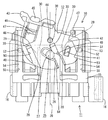
さて、図6に示すように、雄ハウジング11のフード部13の上面には、その前端部寄りであって且つ左右両側端部寄りの位置に、上方に突出すると共に、カムピン25の軸心を通る前後方向の仮想軸(対称軸39)に関して左右対称な位置に1対の係止突部52が形成されている。この係止突部52は、上方から見て、略台形状をなしている。係止突部52の後端縁は、左右方向に延びた直線状をなしており、後述するレバー12の係止受け部53の後端縁と当接するようになっている。係止突部52のうち、雄ハウジング11に対して左右方向における外側の側面は、前後方向に延びた直線状をなしており、後述する雌ハウジング10の案内壁55の内周面と摺接可能になっている。係止突部52のうち、雄ハウジング11に対して左右方向における内側の側面は、レバー12の側端縁と対応する略円弧状をなしており、レバー12の側端縁を逃がすようになっている。   Now, as shown in FIG. 6, the upper surface of the hood 13 of the male housing 11 protrudes upward at a position near its front end and near both left and right ends, and the axis of the cam pin 25 is centered. A pair of locking projections 52 are formed at positions symmetrical with respect to the passing virtual axis (symmetric axis 39) in the front-rear direction. The locking projection 52 has a substantially trapezoidal shape when viewed from above. The rear end edge of the locking projection 52 has a linear shape extending in the left-right direction, and comes into contact with a rear end edge of a locking receiving portion 53 of the lever 12 described later. Outer side surfaces of the locking projections 52 in the left-right direction with respect to the male housing 11 are linearly extending in the front-rear direction, and are in sliding contact with an inner peripheral surface of a guide wall 55 of the female housing 10 described later. It is possible. Of the locking projection 52, the inner side surface in the left-right direction with respect to the male housing 11 has a substantially arc shape corresponding to the side edge of the lever 12, and the side edge of the lever 12 escapes. ing.

一方、レバー12のうち、操作部43と反対側の端部(図1における右端部)には、側板42の側端縁から外方に突出して、係止受け部53が形成されている。係止受け部53の後端縁は左右方向に延びた直線状をなしており、上述した係止突部52の後端縁と整合するようになっている。また、外筒部31の上側のうち、雄ハウジング11と嵌合する側の端面には、雄ハウジング11の係止突部52に対応する位置に、前後方向に延びると共に案内リブ28を逃がすための逃げ孔54が、対称軸39に対して左右対称に形成されている(図1及び図4参照)。この逃げ孔54の内側壁は、両ハウジング10,11が嵌合、離脱する際に、係止突部52の外側壁と摺接することで、両ハウジング10,11の嵌合、離脱を案内する案内壁55とされる。   On the other hand, an end of the lever 12 opposite to the operation portion 43 (a right end portion in FIG. 1) is formed with a latch receiving portion 53 that protrudes outward from the side edge of the side plate 42. The rear end edge of the latch receiving portion 53 has a linear shape extending in the left-right direction, and is aligned with the rear end edge of the latch protrusion 52 described above. Further, in the upper side of the outer cylindrical portion 31, the end surface on the side fitted with the male housing 11 extends in the front-rear direction and escapes the guide rib 28 at a position corresponding to the locking projection 52 of the male housing 11. Are formed symmetrically with respect to the symmetry axis 39 (see FIGS. 1 and 4). When the housings 10 and 11 are fitted and detached, the inner wall of the escape hole 54 is in sliding contact with the outer wall of the locking projection 52 to guide the fitting and removal of the housings 10 and 11. The guide wall 55 is used.

続いて、両ハウジング10,11の嵌合操作の進行状態における各部材の構成について説明する。まず、両ハウジング10,11が図6に示す状態においては、雌ハウジング10に配されたレバー12は、係止片41が受け部29に係合すると共に、保持用段差部48が戻り規制部47と係合することにより、待受け位置において回動不能に保持されている。この状態では、レバー12のカム溝26の入口が前方を向くようになっており、雄ハウジング11のカムピン25がカム溝26に進入するのを許容するようになっている。   Then, the structure of each member in the progress state of fitting operation of both the housings 10 and 11 is demonstrated. First, when both housings 10 and 11 are in the state shown in FIG. 6, the lever 12 disposed in the female housing 10 has the engaging piece 41 engaged with the receiving portion 29 and the holding step portion 48 is returned to the return regulating portion. By being engaged with 47, it is held unrotatable at the standby position. In this state, the inlet of the cam groove 26 of the lever 12 faces forward, and the cam pin 25 of the male housing 11 is allowed to enter the cam groove 26.

次に、両ハウジング10,11が図7に示す位置に移動した状態においては、カムピン25がレバー12の上溝の入口に進入している。このとき、案内リブ28は、切欠部40内に進入しており、この状態においては、係止片41が案内リブ28に乗り上げて上方に撓み変形している。これにより係止片41と受け部29との係合が解除されることで、レバー12が待受け位置から図7における反時計回り方向に回動可能になっている。また、案内リブ28の側壁のうち、左右方向について外側の側壁は、受け部29の内側縁と摺接して、両ハウジング10,11を案内するようになっている。   Next, when both the housings 10 and 11 are moved to the positions shown in FIG. 7, the cam pin 25 enters the entrance of the upper groove of the lever 12. At this time, the guide rib 28 has entered the notch 40. In this state, the locking piece 41 rides on the guide rib 28 and is bent upward and deformed. As a result, the engagement between the locking piece 41 and the receiving portion 29 is released, so that the lever 12 can be rotated counterclockwise in FIG. 7 from the standby position. Of the side walls of the guide rib 28, the outer side wall in the left-right direction is in sliding contact with the inner edge of the receiving portion 29 to guide both housings 10 and 11.

続いて、レバー12が図8に示す位置に回動された状態においては、カムピン25がレバー12のカム溝26に誘導されて、カム溝26内を奥方に移動し、雌ハウジング10と雄ハウジング11とが互いに引き寄せられるように変位するようになっている。また、レバー12のロック突起46は、戻り規制部47に乗り上げて、撓みロック片45は上方に撓み変形するようになっている。   Subsequently, when the lever 12 is rotated to the position shown in FIG. 8, the cam pin 25 is guided to the cam groove 26 of the lever 12 and moves in the cam groove 26, so that the female housing 10 and the male housing are moved. 11 are displaced so as to be attracted to each other. Further, the lock protrusion 46 of the lever 12 rides on the return restricting portion 47, and the bending lock piece 45 is bent upward and deformed.

さらに、レバー12が図1に示す位置に回動された状態においては、両ハウジング10,11は正規嵌合した状態にあり、この状態におけるレバー12の位置が嵌合位置とされる。このとき、レバー12の撓みロック片45のロック突起46は戻り規制部47と係合することでレバー12が時計回りに回動することを防止すると共に、凹部51が戻り規制部47と係合することでレバー12が反時計回りに回動することを防止するようになっている。また、係止突部52が係止受け部53により、雄ハウジング11の嵌合方向の力を受けるようになっており、これにより、両ハウジング10,11の姿勢が矯正されるようになっている。また、係止突部52の前端縁と、逃げ孔54の後端縁とが当接すると共に、案内リブ28の前端縁と、切欠部40の後端縁とが当接することにより両ハウジング10,11の前止まりがなされるようになっている。   Further, when the lever 12 is rotated to the position shown in FIG. 1, the housings 10 and 11 are in a normally fitted state, and the position of the lever 12 in this state is the fitting position. At this time, the lock protrusion 46 of the bending lock piece 45 of the lever 12 engages with the return restricting portion 47 to prevent the lever 12 from rotating clockwise, and the recess 51 engages with the return restricting portion 47. This prevents the lever 12 from rotating counterclockwise. Further, the locking projection 52 receives the force in the fitting direction of the male housing 11 by the locking receiving portion 53, whereby the postures of both the housings 10, 11 are corrected. Yes. Further, the front end edge of the locking projection 52 and the rear end edge of the escape hole 54 are in contact with each other, and the front end edge of the guide rib 28 and the rear end edge of the notch 40 are in contact with each other, Eleven stops are made.

続いて、本実施形態の作用、効果について説明する。雌ハウジング10にレバー12を組付ける際には、レバー収容空間37の天井壁を湾曲変形させると共に、レバー12を待受け位置にあるときと同じ向き(姿勢)にして、後方からレバー収容空間37内に進入させる。このとき、図1における左側の戻り規制部47は、レバー12の戻り規制部逃げ溝50内に進入すると共に、図1における右側の戻り規制部47は、レバー12の凹部51内に進入し、また、支軸38は、レバー12の嵌合溝内に進入し、さらに支軸逃げ溝49内に進入する。これにより、レバー12の組付け時におけるレバー12の雌ハウジング10との嵌合抵抗を減少させることができる。このとき、戻り規制部逃げ溝50及び支軸逃げ溝49にはテーパ面30が形成されているから、戻り規制部47や支軸38の乗り上げ動作が容易になっている。   Then, the effect | action and effect of this embodiment are demonstrated. When the lever 12 is assembled to the female housing 10, the ceiling wall of the lever housing space 37 is curved and deformed, and the lever 12 is placed in the same orientation (posture) as when in the standby position, and the lever housing space 37 is viewed from behind. To enter. At this time, the left return restricting portion 47 in FIG. 1 enters the return restricting portion escape groove 50 of the lever 12, and the right return restricting portion 47 in FIG. 1 enters the recess 51 of the lever 12, Further, the support shaft 38 enters the fitting groove of the lever 12 and further enters the support shaft escape groove 49. Thereby, the fitting resistance with the female housing 10 of the lever 12 at the time of the assembly | attachment of the lever 12 can be reduced. At this time, since the taper surface 30 is formed in the return restricting portion relief groove 50 and the support shaft relief groove 49, the return restricting portion 47 and the support shaft 38 can be easily moved up.

さらにレバー12をレバー収容空間37の奥方に進入させると、支軸38は、支軸逃げ溝49の後端縁に設けられたテーパ面30に乗り上げ、軸孔44に嵌合する。このとき、図1における右側の戻り規制部47は、戻り規制部逃げ溝50の後端縁に設けられたテーパ面30に乗り上げた後、復帰変形して、保持用段差部48と後方から当接することで、レバー12が図1における時計回り方向に回動するのを規制する。また、係止片41は、受け部29に当接することにより、レバー12が図1における反時計回りに回動するのを規制する。これにより、レバー12は、待受け位置において、正逆いずれの方向への回動も規制された状態に保持される。   When the lever 12 is further moved into the depth of the lever housing space 37, the support shaft 38 rides on the tapered surface 30 provided at the rear end edge of the support shaft escape groove 49 and fits into the shaft hole 44. At this time, the right return restricting portion 47 in FIG. 1 rides on the taper surface 30 provided at the rear end edge of the return restricting portion relief groove 50 and then returns and deforms so as to contact the holding stepped portion 48 from the rear. By contacting, the lever 12 is restricted from rotating clockwise in FIG. Further, the locking piece 41 abuts on the receiving portion 29 to restrict the lever 12 from rotating counterclockwise in FIG. As a result, the lever 12 is held in a state where the rotation in either the forward or reverse direction is restricted at the standby position.

この状態で、雄ハウジング11のフード部13を雌ハウジング10に浅く初期嵌合させると、図7に示すように、カムピン25がカム溝26の入口に進入する。このとき、係止突部52は逃げ孔54内に進入すると共に、係止突部52の外側面が、逃げ孔54の案内壁55と摺接することで、両ハウジング10,11の嵌合が案内される。また、案内リブ28が切欠部40内に進入し、この案内リブ28の前端部が係止片41と当接し、係止片41が案内リブ28に乗り上げて上方に撓み変形することで、係止片41と受け部29との係合が解除され、レバー12が図7における反時計回り方向に回動可能になる。このとき、テーパ面30が形成されているから、係止片41が案内リブ28に乗り上げる動作が容易になっている。   In this state, when the hood portion 13 of the male housing 11 is shallowly initially fitted to the female housing 10, the cam pin 25 enters the inlet of the cam groove 26 as shown in FIG. At this time, the locking projection 52 enters the escape hole 54, and the outer surface of the locking projection 52 is in sliding contact with the guide wall 55 of the escape hole 54, so that the housings 10 and 11 are fitted. Guided. Further, the guide rib 28 enters the notch 40, the front end portion of the guide rib 28 comes into contact with the locking piece 41, and the locking piece 41 rides on the guide rib 28 and bends upward to be deformed. The engagement between the stop piece 41 and the receiving portion 29 is released, and the lever 12 can be rotated counterclockwise in FIG. At this time, since the tapered surface 30 is formed, the operation of the locking piece 41 riding on the guide rib 28 is facilitated.

この状態から、操作部43を押圧して、レバー12を支軸38を中心として反時計回り方向に回動させると、図8に示す位置に至る。このとき、カムピン25はカム溝26に誘導されて、両ハウジング10,11が嵌合する方向に互いに引き寄せられる。この状態では、撓みロック片45は、ロック突起46が戻り規制部47に乗り上げることで上方に撓み変形し始める。また、案内リブ28の外側面が受け部29の内側縁と摺接することで、両ハウジング10,11の嵌合が案内される。   From this state, when the operating portion 43 is pressed and the lever 12 is rotated counterclockwise about the support shaft 38, the position shown in FIG. 8 is reached. At this time, the cam pin 25 is guided to the cam groove 26 and is pulled toward each other in the direction in which both the housings 10 and 11 are fitted. In this state, the bending lock piece 45 starts to bend upward and deform as the lock protrusion 46 rides on the return restricting portion 47. Further, when the outer surface of the guide rib 28 is in sliding contact with the inner edge of the receiving portion 29, the fitting of the housings 10 and 11 is guided.

さらに嵌合が進行して図9に示す位置、すなわり、両ハウジング10,11が正規嵌合状態に至る直前の状態になると、レバー12の操作部43は、雌ハウジング10の後端部のうち図9における左側の側端部に位置するようになっており、この状態でレバー12の操作部43を押圧操作すると、雌ハウジング10は、その嵌合方向(図9における下方)に沿う方向の力を受ける。すると、図には詳細に示さないが、雌ハウジング10のうち、図9における左側の嵌合状態が先行し、雌ハウジング10が図9において、左下がりの傾き姿勢になる場合がある。   When the fitting further proceeds and the position shown in FIG. 9, that is, the state immediately before both housings 10 and 11 reach the normal fitting state, the operation portion 43 of the lever 12 is the rear end portion of the female housing 10. 9 is positioned at the left side end portion in FIG. 9, and when the operation portion 43 of the lever 12 is pressed in this state, the female housing 10 follows its fitting direction (downward in FIG. 9). Receive direction force. Then, although not shown in detail in the drawing, in the female housing 10, the left-side fitting state in FIG. 9 precedes, and the female housing 10 may have a downwardly inclined posture in FIG.

上記の状態から、さらに操作部43を押圧すると、図1に示すように、係止受け部53が係止突部52と係合し、これにより、係止突部52は、係止受け部53を介して、雄ハウジング11の嵌合方向に沿う方向(図1における上方)の力を受ける。すると、図9における左下がりの傾き姿勢にあった雌ハウジング10の右側に、雄ハウジング11が進入する方向の力が働くことにより、雌ハウジング10の傾き姿勢が正規の姿勢に矯正される。この状態で、操作部43を押圧することにより、両ハウジング10,11が正規姿勢にある状態で嵌合が完了する。この状態では、撓みロック片45が復帰変形して、図1における左側の戻り規制部47と、撓みロック片45のロック突起46とが係合して、レバー12が図1における時計回り方向に回動するのを規制する。また、図1における右側の戻り規制部47と、凹部51の側壁とが係合して、レバー12が図1における反時計回り方向に回動するのを規制している。そして、係止突部52の前端縁が逃げ孔54の後端縁と当接すると共に、案内リブ28の前端縁が切欠部40の後端縁と当接することで、両ハウジング10,11の前止まりが図られている。   When the operation portion 43 is further pressed from the above state, as shown in FIG. 1, the latch receiving portion 53 engages with the latching projection 52, and thereby the latch projection 52 is engaged with the latch receiving portion. A force in a direction along the fitting direction of the male housing 11 (upward in FIG. 1) is received via 53. Then, the force in the direction in which the male housing 11 enters the right side of the female housing 10 in the downwardly inclined posture in FIG. 9 corrects the tilted posture of the female housing 10 to a normal posture. By pressing the operating portion 43 in this state, the fitting is completed in a state where both the housings 10 and 11 are in the normal posture. In this state, the bending lock piece 45 is restored and deformed, and the return restricting portion 47 on the left side in FIG. 1 engages with the lock protrusion 46 of the bending lock piece 45 so that the lever 12 rotates in the clockwise direction in FIG. The rotation is restricted. Further, the right-side return restricting portion 47 in FIG. 1 and the side wall of the concave portion 51 are engaged to restrict the lever 12 from rotating counterclockwise in FIG. The front end edge of the locking projection 52 contacts the rear end edge of the escape hole 54, and the front end edge of the guide rib 28 contacts the rear end edge of the notch 40. The stop is being planned.

このロック状態から両ハウジング10,11を離脱させる際には、撓みロック片45の後端部を下から指で押し上げて上方へ撓み変形させる。すると、ロック突起46が左側の戻り規制部47から解離し、嵌合位置にあるレバー12が待受け位置側への回動が許容される。このロック解除状態を保ったままで、操作部43を摘んでレバー12を図1における時計回り方向に回動させる。すると、カムピン25がカム溝26に誘導されて、両ハウジング10,11が解離する方向に変位し、レバー12が待受け位置に達すると、両ハウジング10,11は図7に示す状態に至る。この状態から、両ハウジング10,11を離脱させればよい。   When the two housings 10 and 11 are detached from this locked state, the rear end portion of the bending lock piece 45 is pushed up with a finger from below to bend and deform upward. Then, the lock protrusion 46 is disengaged from the left return regulating portion 47, and the lever 12 in the fitting position is allowed to turn to the standby position side. While maintaining this unlocked state, the operating portion 43 is grasped and the lever 12 is rotated in the clockwise direction in FIG. Then, the cam pin 25 is guided to the cam groove 26 and is displaced in a direction in which both the housings 10 and 11 are disengaged. When the lever 12 reaches the standby position, both the housings 10 and 11 reach the state shown in FIG. From this state, both the housings 10 and 11 may be detached.

上記の説明では、レバー12が、待受け位置から嵌合位置に向かって反時計回り方向へ回動されると共に、嵌合位置では操作部43が左端部に位置する向きで雌ハウジング10に組み付けられているが、本実施形態では、レバー12を上記とは左右反転した姿勢で雌ハウジング10に組付けることもできる。そのための手段として、レバー12が上下対称な形状とされ、カム溝26の入口が、レバー12が待受け位置にある状態でレバー12の支軸38を通る対称軸39上に配されるように設けられ、戻り規制部47が対称軸39に関して左右対称な2位置に配され、係止突部52が対称軸39に関して左右対称な2位置に配され、逃げ孔54が対称軸39に関して左右対称な2位置に配され、案内リブ28が対称軸39に対して左右対称な2位置に配され、受け部29が対称軸39に関して左右対称に内方に突設されている。   In the above description, the lever 12 is rotated counterclockwise from the standby position toward the mating position, and the operation portion 43 is assembled to the female housing 10 in the orientation at the left end at the mating position. However, in this embodiment, the lever 12 can also be assembled to the female housing 10 in a posture that is horizontally reversed from the above. As a means for this, the lever 12 has a vertically symmetrical shape, and the inlet of the cam groove 26 is provided on a symmetrical axis 39 that passes through the support shaft 38 of the lever 12 in a state where the lever 12 is in the standby position. The return restricting portion 47 is disposed at two positions symmetrical with respect to the symmetry axis 39, the locking projection 52 is disposed at two positions symmetrical with respect to the symmetry axis 39, and the escape hole 54 is symmetrical with respect to the symmetry axis 39. The guide ribs 28 are arranged at two positions that are bilaterally symmetrical with respect to the symmetry axis 39, and the receiving portion 29 protrudes inward symmetrically with respect to the symmetry axis 39.

レバー12が上記と左右反転した状態で組み付けられた場合には、待受け位置から嵌合位置に向かって時計回り方向へ回動されると共に、嵌合位置では、操作部43が右端部に位置する向きで雌ハウジング10に組み付けられる。また、レバー12を雌ハウジング10に組付けた後、レバー12を待受け位置から嵌合位置にまで回動して両ハウジング10,11を嵌合させる手順は、上記とは左右対称となるので、作用の説明は省略する。   When the lever 12 is assembled in a state where it is reversed left and right, the lever 12 is rotated clockwise from the standby position toward the fitting position, and the operation portion 43 is located at the right end portion at the fitting position. It is assembled to the female housing 10 in the direction. In addition, since the lever 12 is assembled to the female housing 10 and then the lever 12 is rotated from the standby position to the fitting position and the housings 10 and 11 are fitted to each other, the above is symmetrical with the above. The explanation of the action is omitted.

以上説明したように、本実施形態においては、両ハウジング10,11が正規嵌合する直前において、雌ハウジング10のうち、レバー12の操作部43の近傍に位置する側端部の嵌合状態が、レバー12の操作部43と反対側に位置する側端部よりも先行している場合に、雄ハウジング11の係止突部52と、レバー12の操作部43の反対側に形成した係止受け部53とが係合することにより、係止突部52が、雄ハウジング11の嵌合方向に沿う方向の力を受けることで、雌ハウジング10の姿勢が矯正されて、両ハウジング10,11が正規姿勢で嵌合することができる。   As described above, in this embodiment, immediately before the housings 10 and 11 are properly fitted, the fitted state of the side end portion of the female housing 10 that is located in the vicinity of the operation portion 43 of the lever 12 is the same. The locking protrusion 52 of the male housing 11 and the locking formed on the opposite side of the operating portion 43 of the lever 12 when preceding the side end located on the opposite side of the operating portion 43 of the lever 12 By engaging the receiving portion 53, the locking projection 52 receives a force in the direction along the fitting direction of the male housing 11, whereby the posture of the female housing 10 is corrected, and both the housings 10, 11 are corrected. Can be fitted in a normal posture.

さらに、雌ハウジング10の係止突部52は、雄ハウジング11に形成された案内壁55と摺接することで、両ハウジング10,11の嵌合、離脱を案内して、両ハウジング10,11が正規姿勢で嵌合するようになっている。   Further, the locking projection 52 of the female housing 10 is in sliding contact with a guide wall 55 formed on the male housing 11, thereby guiding the fitting and detachment of both the housings 10, 11. It fits in a normal posture.

また、1種類のレバー12を雌ハウジング10に対し、対称軸39に関して左右対称な2つの姿勢のうちいずれの姿勢でも組付けることが可能になっているから、レバー式コネクタが配置される状況に応じて、レバー12の組付け位置を適宜選択することにより、レバー12の回動操作性を向上させることができる。   In addition, since one type of lever 12 can be assembled to the female housing 10 in any of two postures that are bilaterally symmetric with respect to the symmetry axis 39, a lever-type connector is disposed. Accordingly, the operability of turning the lever 12 can be improved by appropriately selecting the assembly position of the lever 12.

<参考例>
次に、参考例を図10及び図11によって説明する。本実施形態に係るレバー式コネクタは、第1ハウジング56と、第2ハウジング57とを、第1ハウジング56に配設したレバー12により嵌合、離脱させるようにしたものである。なお、以下の説明では、両ハウジング56,57の嵌合方向を前方とする。
<Reference example>
Next, a reference example will be described with reference to FIGS. The lever type connector according to the present embodiment is configured such that the first housing 56 and the second housing 57 are fitted and detached by the lever 12 disposed in the first housing 56. In the following description, the fitting direction of both housings 56 and 57 is the front.

第2ハウジング57は、固定部材63の壁面から外方に突出しており、待受け側ハウジングとされる。第2ハウジング57の上壁の外側面には、その前端部寄りの位置に、略円柱状をなす1対のカムピン25が形成されている。両カムピン25,25は、第2ハウジング57の左右方向の幅寸法の中央を通り、両ハウジング10,11の嵌合方向と平行な対称軸39に対して、左右対称な位置に配されている。両カムピン25,25の上端部には、径方向について外方に拡径された拡径部27が形成されている。   The second housing 57 protrudes outward from the wall surface of the fixing member 63 and serves as a standby housing. A pair of cam pins 25 having a substantially cylindrical shape is formed on the outer surface of the upper wall of the second housing 57 at a position near its front end. Both cam pins 25, 25 pass through the center of the width dimension in the left-right direction of the second housing 57, and are disposed at positions symmetrical with respect to the symmetry axis 39 parallel to the fitting direction of the two housings 10, 11. . A diameter-expanded portion 27 that is expanded outward in the radial direction is formed at the upper ends of both cam pins 25, 25.

第1ハウジング56は、ワイヤーハーネスを構成する電線19と接続されており、ハーネス側ハウジングとされる。第1ハウジング56の上壁の外側面には、後端寄りの位置に、略円柱状をなす1対の支軸38が形成されている。両支軸38,38は、第1ハウジング56の左右方向の幅寸法の中央を通り、両ハウジング10,11の嵌合方向に平行な対称軸39に対して左右対称に配されている。両支軸38,38の上端部には、左右に突出する1対の突部58が形成されている。   The 1st housing 56 is connected with the electric wire 19 which comprises a wire harness, and is taken as a harness side housing. On the outer surface of the upper wall of the first housing 56, a pair of support shafts 38 having a substantially cylindrical shape is formed at a position near the rear end. Both the support shafts 38, 38 are arranged symmetrically with respect to a symmetry axis 39 that passes through the center of the width dimension in the left-right direction of the first housing 56 and is parallel to the fitting direction of both the housings 10, 11. A pair of protrusions 58 protruding left and right are formed at the upper ends of both the support shafts 38, 38.

第1ハウジング56の上壁の前端部には、左右方向の略中央付近に、その前端縁から後方に向かって略矩形状に切欠された切欠部40が、対称軸39に関して左右対称に形成されている。この切欠部40の左右両外方には、左右1対の板状の押さえ部59が設けられている。両押さえ部59,59は、左右方向に細長い略矩形状をなしており、第1ハウジング56の上壁に対して平行に配置されている。右側の押さえ部59のうち左後部の角部は切り欠かれており、レバー12との干渉を防止するようになっていると共に、後述するレバー12の張出し部62を上方から押さえるひさし部60が形成されている。また同様に、左側の押さえ部59のうち右後部の角部は切り欠かれており、レバー12との干渉を防止するようになっていると共に、レバー12の張出し部62を上方から押さえるひさし部60が形成されている。   At the front end portion of the upper wall of the first housing 56, a notch portion 40 that is cut out in a substantially rectangular shape from the front end edge to the rear side is formed in the left-right symmetric direction with respect to the symmetry axis 39 in the vicinity of the center in the left-right direction. ing. A pair of left and right plate-shaped pressing parts 59 are provided on both the left and right sides of the notch 40. Both pressing parts 59, 59 have a substantially rectangular shape elongated in the left-right direction, and are arranged in parallel to the upper wall of the first housing 56. A corner portion of the left rear portion of the right holding portion 59 is cut away so as to prevent interference with the lever 12, and an eave portion 60 that holds a protruding portion 62 of the lever 12 described later from above is provided. Is formed. Similarly, the corner portion of the right rear portion of the left pressing portion 59 is notched so as to prevent interference with the lever 12 and an eave portion for pressing the protruding portion 62 of the lever 12 from above. 60 is formed.

図10に示すように、レバー12は、概ね、上方から見て、円の周縁部のうちの後端部領域を櫛形に切欠した形状をなす側板42と、側板42の右端から右方に突出されてなり、略矩形状をなす操作部43とを備えてなる。レバー12は全体として上下対称な形状となっている。このレバー12は、第1ハウジング56に対して、図10における右側の支軸38に取付けられており、待受け位置と、嵌合位置との間で回動可能になっている。なお、レバー12の説明における前後左右の向きについては、レバー12が嵌合位置にある状態を基準とする(図10参照)。   As shown in FIG. 10, when viewed from above, the lever 12 generally protrudes rightward from the right end of the side plate 42 and the side plate 42 having a shape in which the rear end region of the peripheral edge of the circle is notched in a comb shape. And an operation portion 43 having a substantially rectangular shape. The lever 12 has a vertically symmetrical shape as a whole. The lever 12 is attached to the right support shaft 38 in FIG. 10 with respect to the first housing 56 and is rotatable between a standby position and a fitting position. Note that the front, rear, left, and right directions in the description of the lever 12 are based on the state where the lever 12 is in the fitting position (see FIG. 10).

側板42の中心には、支軸38の形状に適合した形状をなす軸孔44が上下に貫通して形成されており、上述した支軸38が貫通するようになっており、その外側には、レバー12が回動する際に支軸38の突部58を逃がせるように円形孔61が形成されている。また、側板42における軸孔44の前方には、軸孔44を中心とする周方向及び径方向の双方に対して斜めをなすカム溝26が形成されている。カム溝26の上端縁には、カムピン25の拡径部27を受けるカムピン受け部64が、カム溝26の全長に亘って形成されている。側板42における軸孔44よりも左方の位置には、レバー12を待受け位置に保持するための係止片41が形成されている。この係止片41は、前後方向に細長い板状をなし、その前端において側板42に対して後方へ片持ち状に延出する形態となっている。この撓み係止片41は、その基端部(前端部)を支点として、上下方向に撓み変形可能になっている。撓み片の後端部は、レバー12が待受け位置にある場合に、切欠部40の後端縁と係合するようになっている。側板42の前端縁には、径方向外方へ側板42と同心円弧状に張出した張出し部62が形成されている。張出し部62の上面は、側板42の上面に対して段差状に低くなっている。   A shaft hole 44 having a shape suitable for the shape of the support shaft 38 is formed in the center of the side plate 42 so as to penetrate vertically, and the support shaft 38 described above passes therethrough, A circular hole 61 is formed so that the protrusion 58 of the support shaft 38 can escape when the lever 12 rotates. Further, a cam groove 26 is formed in front of the shaft hole 44 in the side plate 42 so as to be inclined with respect to both the circumferential direction and the radial direction with the shaft hole 44 as the center. A cam pin receiving portion 64 that receives the enlarged diameter portion 27 of the cam pin 25 is formed at the upper end edge of the cam groove 26 over the entire length of the cam groove 26. A locking piece 41 for holding the lever 12 in the standby position is formed at a position on the left side of the shaft hole 44 in the side plate 42. This locking piece 41 has a plate shape elongated in the front-rear direction, and has a form that cantilevered backward with respect to the side plate 42 at its front end. The bending locking piece 41 can be bent and deformed in the vertical direction with the base end portion (front end portion) as a fulcrum. The rear end portion of the bending piece is configured to engage with the rear end edge of the cutout portion 40 when the lever 12 is in the standby position. At the front end edge of the side plate 42, an overhanging portion 62 is formed that extends radially outward in a concentric arc shape with the side plate 42. The upper surface of the overhanging portion 62 is stepped lower than the upper surface of the side plate 42.

さて、側板42のうち、カム溝26の入口の左方には、側板42の側縁から径方向外方に鉤状に突出した係止受け部53が形成されている。この係止受け部53は、レバー12が嵌合位置にある状態において、係止受け部53の後端縁が、図11の左側のカムピン25に係合するようになっている。   In the side plate 42, an engagement receiving portion 53 is formed on the left side of the inlet of the cam groove 26 and protrudes in a hook shape radially outward from the side edge of the side plate 42. The latch receiving portion 53 is configured such that the rear end edge of the latch receiving portion 53 engages with the left cam pin 25 in FIG.

続いて、本参考例の作用、効果について説明する。レバー12の軸孔44の形状を支軸38の突部58の位置と適合させながら、軸孔44に支軸38を貫通させた後、レバー12を待受け位置にまで回動させる(図10参照)。すると、係止片41の先端が切欠部40の後端縁と当接すると共に、図示しない保持手段により、レバー12が正逆いずれの方向への回動を規制された状態に保持される。このとき、張出し部62の上方に押さえ部59が位置するようになっており、レバー12が上方に変位するのを規制する。   Then, the effect | action and effect of this reference example are demonstrated. While the shape of the shaft hole 44 of the lever 12 is matched with the position of the protrusion 58 of the support shaft 38, the support shaft 38 is passed through the shaft hole 44, and then the lever 12 is rotated to the standby position (see FIG. 10). ). Then, the front end of the locking piece 41 comes into contact with the rear end edge of the notch 40, and the lever 12 is held in a state in which the rotation in the forward or reverse direction is restricted by a holding means (not shown). At this time, the pressing portion 59 is positioned above the overhang portion 62 and restricts the lever 12 from being displaced upward.

この状態で、第2ハウジング57を第1ハウジング56に浅く初期嵌合させて、図10における右側のカムピン25をカム溝26の入口に進入させる。すると、図示しない係合解除部が係止片41と当接し、係止片41が係合解除部に乗り上げて上方に撓み変形することで、係止片41と切欠部40との係合が解除され、レバー12が図10における時計回り方向に回動可能になる。   In this state, the second housing 57 is shallowly initially fitted to the first housing 56, and the right cam pin 25 in FIG. Then, the engagement releasing portion (not shown) comes into contact with the locking piece 41, and the locking piece 41 rides on the engagement releasing portion and bends and deforms upward so that the engagement between the locking piece 41 and the cutout portion 40 is performed. The lever 12 is released and can be rotated clockwise in FIG.

この状態から、操作部43を押圧して、レバー12を支軸38を中心として時計回り方向に回動させると、カムピン25はカム溝26に誘導されて、両ハウジング56,57が嵌合する方向に互いに引き寄せられる。さらに嵌合が進行して、図10に示すように、係止受け部53が、図11における左側のカムピン25と係合し、これにより、左側のカムピン25は、係止受け部53を介して、第2ハウジング57の嵌合方向に沿う方向(図1における上方)の力を受ける。これにより、第2ハウジング57が正規の姿勢に矯正される。この状態で、操作部43を押圧することにより、両ハウジング56,57が正規姿勢にある状態で嵌合が完了する。この状態では、図示しないレバー保持手段により、レバー12が図11における反時計回り方向に回動するのを規制される。また、カムピン25の前端部が切欠部40の後端縁と当接することで、両ハウジング56,57の前止まりが図られている。   From this state, when the operating portion 43 is pressed and the lever 12 is rotated clockwise about the support shaft 38, the cam pin 25 is guided to the cam groove 26 and the housings 56 and 57 are fitted. Attracted to each other in the direction. As the fitting further proceeds, as shown in FIG. 10, the latch receiving portion 53 is engaged with the left cam pin 25 in FIG. 11, whereby the left cam pin 25 is interposed via the latch receiving portion 53. Thus, a force in a direction along the fitting direction of the second housing 57 (upward in FIG. 1) is received. Thereby, the second housing 57 is corrected to a normal posture. By pressing the operating portion 43 in this state, the fitting is completed in a state where both the housings 56 and 57 are in the normal posture. In this state, the lever 12 is restricted from rotating counterclockwise in FIG. 11 by a lever holding means (not shown). Further, the front ends of the cam pins 25 are brought into contact with the rear end edges of the cutout portions 40, whereby the front stops of the housings 56 and 57 are achieved.

上記の説明では、レバー12が、図10における右側の支軸38に取付けられて、待受け位置から嵌合位置に向かって時計回り方向へ回動されると共に、嵌合位置では操作部43が右端部に位置する向きで第1ハウジング56に組み付けられているが、本参考例では、レバー12を左側の支軸38に取付けると共に、上記とは左右反転した姿勢で第1ハウジング56に組付けることもできる。このとき、係止受け部53は、右側のカムピン25に係合するようになっている。   In the above description, the lever 12 is attached to the right support shaft 38 in FIG. 10 and is rotated clockwise from the standby position toward the fitting position, and the operation portion 43 is at the right end at the fitting position. In this reference example, the lever 12 is attached to the left support shaft 38 and is attached to the first housing 56 in a posture that is horizontally reversed from the above. You can also. At this time, the latch receiving portion 53 is adapted to engage with the right cam pin 25.

レバー12が上記と左右反転した状態で組み付けられた場合には、待受け位置から嵌合位置に向かって反時計回り方向へ回動されると共に、嵌合位置では、操作部43が左端部に位置する向きで第1ハウジング56に組み付けられる。また、レバー12を第1ハウジング56に組付けた後、レバー12を待受け位置から嵌合位置にまで回動して両ハウジング56,57を嵌合させる手順は、上記とは左右対称となるので、作用の説明は省略する。   When the lever 12 is assembled in a state where it is reversed left and right as described above, the lever 12 is rotated counterclockwise from the standby position toward the fitting position, and at the fitting position, the operation unit 43 is positioned at the left end. The first housing 56 is assembled in such a direction. Further, after the lever 12 is assembled to the first housing 56, the procedure for turning the lever 12 from the standby position to the fitting position and fitting the two housings 56 and 57 is symmetrical with the above. The description of the action is omitted.

本参考例によれば、レバー12が嵌合位置にある状態において、カム溝26と係合しない側のカムピン25と係合する構成とされるから、係止突部52を別途設ける場合に比べて第2ハウジング57の構造を簡素化できる。   According to this reference example, the lever 12 is engaged with the cam pin 25 on the side not engaged with the cam groove 26 when the lever 12 is in the fitting position. Thus, the structure of the second housing 57 can be simplified.

<他の実施形態>
本発明は上記記述及び図面によって説明した実施形態に限定されるものではなく、例えば次のような実施形態も本発明の技術的範囲に含まれ、さらに、下記以外にも要旨を逸脱しない範囲内で種々変更して実施することができる。
(1)実施形態1においては、レバー12は板状をなしていたが、これに限られず、1対の側板42の端部を操作部43により連結した略門形状をなすものとしてもよい。この場合、雌ハウジング10の上面側だけでなく、下面側についても、嵌合姿勢を矯正できるから、両ハウジング10,11の嵌合姿勢を一層安定させることができる。
(2)実施形態1においては、レバー12は対称軸39に対して左右方向に付け替え可能に配設される構成としたが、これに限られず、一方向のみに配設される構成としてもよい。場合には、係止突部52は1つだけ形成される構成としてもよい。
(3)実施形態1においては、雌ハウジング10のうち、雄ハウジング11と嵌合する側の端面には、係止突部52を逃げると共に案内するための案内壁55が形成される構成としたが、これに限られず、雌ハウジング10には、係止突部52に対応する位置の肉を除去することで係止突部52を逃がす構成としてもよい。
(4)実施形態1においては、第1ハウジングは雌ハウジング10とし、第2ハウジングは雄ハウジング11としたが、これに限られず、第1ハウジングを雄ハウジング11とし、第2ハウジングを雌ハウジング10としてもよい。
(5)実施形態1においては、雄ハウジング11は、取付けロック部16により固定部材に固定される構成としたが、これに限られず、固定部材の壁面から突設される構成としてもよい。
<Other embodiments>
The present invention is not limited to the embodiments described with reference to the above description and drawings. For example, the following embodiments are also included in the technical scope of the present invention, and further, within the scope not departing from the gist of the invention other than the following. Various modifications can be made.
(1) In the first embodiment, the lever 12 has a plate shape. However, the present invention is not limited to this, and the lever 12 may have a substantially portal shape in which the end portions of the pair of side plates 42 are connected by the operation unit 43. In this case, since the fitting posture can be corrected not only on the upper surface side of the female housing 10 but also on the lower surface side, the fitting postures of both housings 10 and 11 can be further stabilized.
(2) In the first embodiment, the lever 12 is arranged so as to be replaceable in the left-right direction with respect to the symmetry axis 39, but is not limited thereto, and may be arranged in only one direction. . In some cases, only one locking protrusion 52 may be formed.
(3) In the first embodiment, a guide wall 55 for escaping and guiding the locking projection 52 is formed on the end surface of the female housing 10 on the side to be fitted with the male housing 11. However, the present invention is not limited to this, and the female housing 10 may be configured such that the locking protrusion 52 is released by removing the meat at a position corresponding to the locking protrusion 52.
(4) In the first embodiment, the first housing is the female housing 10 and the second housing is the male housing 11. However, the first housing is the male housing 11 and the second housing is the female housing 10. It is good.
(5) In the first embodiment, the male housing 11 is configured to be fixed to the fixing member by the mounting lock portion 16, but is not limited thereto, and may be configured to protrude from the wall surface of the fixing member.

10…雌ハウジング(第1ハウジング)
11…雄ハウジング(第2ハウジング)
12…レバー
19…電線
25…カムピン
26…カム溝
38…支軸
42…側板
43…操作部
52…係止突部
53…係止受け部
55…案内壁
56…第1ハウジング
57…第2ハウジング
10: Female housing (first housing)
11 ... male housing (second housing)
DESCRIPTION OF SYMBOLS 12 ... Lever 19 ... Electric wire 25 ... Cam pin 26 ... Cam groove 38 ... Support shaft 42 ... Side plate 43 ... Operation part 52 ... Locking protrusion 53 ... Locking receiving part 55 ... Guide wall 56 ... 1st housing 57 ... 2nd housing

Claims (3)

側板の先端部に操作部を有する1枚板状のレバーが第1ハウジングに回動可能に組み付けられ、前記レバーの回動操作により前記側板に形成されたカム溝に沿って第2ハウジングに形成されたカムピンを誘導することで両ハウジングを嵌合状態とすることができるようになっていると共に、
前記両ハウジングが正規嵌合する直前には、前記レバーの操作部は、前記第1ハウジングの側端部のうち、前記レバーの回動軸からこの回動軸の径方向に離間した側端部の近傍に位置して、前記第1ハウジングの嵌合方向に沿う方向に操作されるようになっているレバー式コネクタであって、
前記第2ハウジングには係止突部が形成されており、前記レバーのうち前記操作部と反対側の端部には、前記係止突部と係合する係止受け部が形成されており、前記係止突部と前記係止受け部とは、前記両ハウジングが正規嵌合する直前に係合し、前記レバーの回動操作により、前記係止突部は、前記係止受け部を介して前記第2ハウジングの嵌合方向に沿う方向の力を受けるようになっており、
前記レバーが、前記第1ハウジングに対して、左右方向に関して対称な2つの姿勢での組み付けを可能とされ、
前記係止突部が、前記第2ハウジングに左右で対をなして形成され、
前記第1ハウジングには、前記両係止突部と対応する位置に、前記両ハウジングの嵌合方向に沿って延びて、前記両ハウジングの嵌合時に前記両係止突部のそれぞれが摺接する左右1対の案内壁が形成されていることを特徴とするレバー式コネクタ。
A single plate-like lever having an operating portion at the front end of the side plate is rotatably assembled to the first housing, and is formed in the second housing along a cam groove formed in the side plate by the turning operation of the lever. Both the housings can be brought into a fitted state by guiding the cam pins that are made,
Immediately before the two housings are properly fitted, the operating portion of the lever is a side end portion of the side end portion of the first housing that is spaced apart from the rotating shaft of the lever in the radial direction of the rotating shaft. Is a lever-type connector that is adapted to be operated in a direction along the fitting direction of the first housing,
The second housing is formed with a locking projection, and an end of the lever opposite to the operation unit is formed with a locking receiving portion that engages with the locking projection. The locking projection and the locking receiving portion are engaged immediately before the two housings are properly fitted, and the locking protruding portion causes the locking receiving portion to be moved by a turning operation of the lever. Via a force in a direction along the fitting direction of the second housing,
The lever can be assembled in two postures symmetrical with respect to the left-right direction with respect to the first housing,
The locking protrusions are formed in a pair on the left and right sides of the second housing,
The first housing extends along the fitting direction of the housings at a position corresponding to the locking protrusions, and the locking protrusions are in sliding contact with each other when the housings are fitted. A lever-type connector, wherein a pair of left and right guide walls are formed.
前記第1ハウジングはワイヤーハーネスを構成する電線と接続されるハーネス側ハウジングであり、前記第2ハウジングは固定部材に配設される待受け側ハウジングであることを特徴とする請求項1記載のレバー式コネクタ。   The lever type according to claim 1, wherein the first housing is a harness side housing connected to an electric wire constituting a wire harness, and the second housing is a standby side housing disposed on a fixing member. connector. 前記案内壁及び前記係止突部が、それぞれ前記第1ハウジング及び前記第2ハウジングにおける左右方向の対称位置に配置されている請求項1又は2記載のレバー式コネクタ。   The lever-type connector according to claim 1 or 2, wherein the guide wall and the locking projection are disposed at symmetrical positions in the left-right direction of the first housing and the second housing, respectively.
JP2010020335A 2010-02-01 2010-02-01 Lever type connector Active JP5035359B2 (en)

Priority Applications (1)

Application Number Priority Date Filing Date Title
JP2010020335A JP5035359B2 (en) 2010-02-01 2010-02-01 Lever type connector

Applications Claiming Priority (1)

Application Number Priority Date Filing Date Title
JP2010020335A JP5035359B2 (en) 2010-02-01 2010-02-01 Lever type connector

Related Parent Applications (1)

Application Number Title Priority Date Filing Date
JP2005175262A Division JP4492449B2 (en) 2005-06-15 2005-06-15 Lever type connector

Publications (2)

Publication Number Publication Date
JP2010097954A true JP2010097954A (en) 2010-04-30
JP5035359B2 JP5035359B2 (en) 2012-09-26

Family

ID=42259463

Family Applications (1)

Application Number Title Priority Date Filing Date
JP2010020335A Active JP5035359B2 (en) 2010-02-01 2010-02-01 Lever type connector

Country Status (1)

Country Link
JP (1) JP5035359B2 (en)

Cited By (6)

* Cited by examiner, † Cited by third party
Publication number Priority date Publication date Assignee Title
JP2012164482A (en) * 2011-02-04 2012-08-30 Tyco Electronics Japan Kk Fitting auxiliary tool of electric connector, and fitting method of electric connector
WO2013005629A1 (en) * 2011-07-01 2013-01-10 矢崎総業株式会社 Lever-fitting-type connector
WO2013005628A1 (en) * 2011-07-01 2013-01-10 矢崎総業株式会社 Lever-fitting-type connector
WO2013005627A1 (en) * 2011-07-01 2013-01-10 矢崎総業株式会社 Lever-fitting-type connector
JP2014191985A (en) * 2013-03-27 2014-10-06 Sumitomo Wiring Syst Ltd Lever-type connector
JP2016071575A (en) * 2014-09-30 2016-05-09 沖電気工業株式会社 Paper currency handling apparatus

Citations (4)

* Cited by examiner, † Cited by third party
Publication number Priority date Publication date Assignee Title
JP2002025687A (en) * 2000-07-13 2002-01-25 Sumitomo Wiring Syst Ltd Lever type connector
JP2002141142A (en) * 2000-10-31 2002-05-17 Sumitomo Wiring Syst Ltd Connector
JP2003249303A (en) * 2002-02-26 2003-09-05 Sumitomo Wiring Syst Ltd Lever connector
JP2004241157A (en) * 2003-02-03 2004-08-26 Sumitomo Wiring Syst Ltd Lever type connector

Patent Citations (4)

* Cited by examiner, † Cited by third party
Publication number Priority date Publication date Assignee Title
JP2002025687A (en) * 2000-07-13 2002-01-25 Sumitomo Wiring Syst Ltd Lever type connector
JP2002141142A (en) * 2000-10-31 2002-05-17 Sumitomo Wiring Syst Ltd Connector
JP2003249303A (en) * 2002-02-26 2003-09-05 Sumitomo Wiring Syst Ltd Lever connector
JP2004241157A (en) * 2003-02-03 2004-08-26 Sumitomo Wiring Syst Ltd Lever type connector

Cited By (12)

* Cited by examiner, † Cited by third party
Publication number Priority date Publication date Assignee Title
JP2012164482A (en) * 2011-02-04 2012-08-30 Tyco Electronics Japan Kk Fitting auxiliary tool of electric connector, and fitting method of electric connector
WO2013005629A1 (en) * 2011-07-01 2013-01-10 矢崎総業株式会社 Lever-fitting-type connector
WO2013005628A1 (en) * 2011-07-01 2013-01-10 矢崎総業株式会社 Lever-fitting-type connector
WO2013005627A1 (en) * 2011-07-01 2013-01-10 矢崎総業株式会社 Lever-fitting-type connector
JP2013016317A (en) * 2011-07-01 2013-01-24 Yazaki Corp Lever fitting type connector
JP2013016315A (en) * 2011-07-01 2013-01-24 Yazaki Corp Lever fitting type connector
US9033719B2 (en) 2011-07-01 2015-05-19 Yazaki Corporation Lever-fitting-type connector
US9033720B2 (en) 2011-07-01 2015-05-19 Yazaki Corporation Lever-fitting-type connector
US9048578B2 (en) 2011-07-01 2015-06-02 Yazaki Corporation Lever-fitting-type connector
KR101531319B1 (en) * 2011-07-01 2015-06-24 야자키 소교 가부시키가이샤 Lever-fitting-type connector
JP2014191985A (en) * 2013-03-27 2014-10-06 Sumitomo Wiring Syst Ltd Lever-type connector
JP2016071575A (en) * 2014-09-30 2016-05-09 沖電気工業株式会社 Paper currency handling apparatus

Also Published As

Publication number Publication date
JP5035359B2 (en) 2012-09-26

Similar Documents

Publication Publication Date Title
JP4492449B2 (en) Lever type connector
JP4497038B2 (en) Lever type connector
JP5029872B2 (en) Lever type connector
JP5035359B2 (en) Lever type connector
JP4285376B2 (en) Lever type connector
EP2500984A1 (en) Charging connector and assembling method therefor
JP2006344473A (en) Lever type connector
JP4497108B2 (en) Lever type connector
JP2008103223A (en) Lever connector
JP2004319225A (en) Lever type connector
JP2006120536A (en) Lever type connector
JP2021015719A (en) Lever-type connector
JP2009104934A (en) Connector
JP2003086301A (en) Lever type connector
JP2006147474A (en) Waterproof connector
JP2003208948A (en) Lever-type connector
JP4924901B2 (en) Lock structure and connector
JP4924902B2 (en) Lock structure and connector
JP6252068B2 (en) Lever fitting type connector
JP2009009844A (en) Mounting method of lever-type connector, and lever-type connector
JP2010108872A (en) Lever-type connector
JP2008130322A (en) Connector
JP2008262718A (en) Connector
JP2007048520A (en) Lever type connector
JP4689628B2 (en) Lever type connector

Legal Events

Date Code Title Description
A621 Written request for application examination

Free format text: JAPANESE INTERMEDIATE CODE: A621

Effective date: 20100201

A977 Report on retrieval

Free format text: JAPANESE INTERMEDIATE CODE: A971007

Effective date: 20110912

A131 Notification of reasons for refusal

Free format text: JAPANESE INTERMEDIATE CODE: A131

Effective date: 20110920

A521 Written amendment

Free format text: JAPANESE INTERMEDIATE CODE: A523

Effective date: 20111115

TRDD Decision of grant or rejection written
A01 Written decision to grant a patent or to grant a registration (utility model)

Free format text: JAPANESE INTERMEDIATE CODE: A01

Effective date: 20120605

A01 Written decision to grant a patent or to grant a registration (utility model)

Free format text: JAPANESE INTERMEDIATE CODE: A01

A61 First payment of annual fees (during grant procedure)

Free format text: JAPANESE INTERMEDIATE CODE: A61

Effective date: 20120618

FPAY Renewal fee payment (event date is renewal date of database)

Free format text: PAYMENT UNTIL: 20150713

Year of fee payment: 3

R150 Certificate of patent or registration of utility model

Ref document number: 5035359

Country of ref document: JP

Free format text: JAPANESE INTERMEDIATE CODE: R150

Free format text: JAPANESE INTERMEDIATE CODE: R150