WO2013005465A1 - Vehicle bumper reinforcement - Google Patents
Vehicle bumper reinforcement Download PDFInfo
- Publication number
- WO2013005465A1 WO2013005465A1 PCT/JP2012/060385 JP2012060385W WO2013005465A1 WO 2013005465 A1 WO2013005465 A1 WO 2013005465A1 JP 2012060385 W JP2012060385 W JP 2012060385W WO 2013005465 A1 WO2013005465 A1 WO 2013005465A1
- Authority
- WO
- WIPO (PCT)
- Prior art keywords
- vehicle
- strength
- low
- bumper reinforcement
- vertical direction
- Prior art date
Links
Images


Classifications
-
- B—PERFORMING OPERATIONS; TRANSPORTING
- B60—VEHICLES IN GENERAL
- B60R—VEHICLES, VEHICLE FITTINGS, OR VEHICLE PARTS, NOT OTHERWISE PROVIDED FOR
- B60R19/00—Wheel guards; Radiator guards, e.g. grilles; Obstruction removers; Fittings damping bouncing force in collisions
- B60R19/02—Bumpers, i.e. impact receiving or absorbing members for protecting vehicles or fending off blows from other vehicles or objects
- B60R19/18—Bumpers, i.e. impact receiving or absorbing members for protecting vehicles or fending off blows from other vehicles or objects characterised by the cross-section; Means within the bumper to absorb impact
-
- B—PERFORMING OPERATIONS; TRANSPORTING
- B60—VEHICLES IN GENERAL
- B60R—VEHICLES, VEHICLE FITTINGS, OR VEHICLE PARTS, NOT OTHERWISE PROVIDED FOR
- B60R19/00—Wheel guards; Radiator guards, e.g. grilles; Obstruction removers; Fittings damping bouncing force in collisions
- B60R19/56—Fittings damping bouncing force in truck collisions, e.g. bumpers; Arrangements on high-riding vehicles, e.g. lorries, for preventing vehicles or objects from running thereunder
-
- B—PERFORMING OPERATIONS; TRANSPORTING
- B60—VEHICLES IN GENERAL
- B60R—VEHICLES, VEHICLE FITTINGS, OR VEHICLE PARTS, NOT OTHERWISE PROVIDED FOR
- B60R19/00—Wheel guards; Radiator guards, e.g. grilles; Obstruction removers; Fittings damping bouncing force in collisions
- B60R19/02—Bumpers, i.e. impact receiving or absorbing members for protecting vehicles or fending off blows from other vehicles or objects
- B60R19/18—Bumpers, i.e. impact receiving or absorbing members for protecting vehicles or fending off blows from other vehicles or objects characterised by the cross-section; Means within the bumper to absorb impact
- B60R2019/1806—Structural beams therefor, e.g. shock-absorbing
- B60R2019/1813—Structural beams therefor, e.g. shock-absorbing made of metal
-
- B—PERFORMING OPERATIONS; TRANSPORTING
- B60—VEHICLES IN GENERAL
- B60R—VEHICLES, VEHICLE FITTINGS, OR VEHICLE PARTS, NOT OTHERWISE PROVIDED FOR
- B60R19/00—Wheel guards; Radiator guards, e.g. grilles; Obstruction removers; Fittings damping bouncing force in collisions
- B60R19/02—Bumpers, i.e. impact receiving or absorbing members for protecting vehicles or fending off blows from other vehicles or objects
- B60R19/18—Bumpers, i.e. impact receiving or absorbing members for protecting vehicles or fending off blows from other vehicles or objects characterised by the cross-section; Means within the bumper to absorb impact
- B60R2019/186—Additional energy absorbing means supported on bumber beams, e.g. cellular structures or material
Definitions
- the present invention relates to a bumper reinforcement for a vehicle, and more particularly to an improvement of a bumper reinforcement having a function of preventing the vehicle from getting on and getting into the vehicle.
- the apparatus described in Patent Document 1 is one example, and high strength bumper reinforcement having high tensile strength can be obtained by hot press molding (hot stamping molding).
- Patent Document 2 when quenching and hardening by hot press molding, in order to prevent a load from being lowered at a stretch due to buckling (bending) of a load input portion, a low-strength portion whose quenching is locally relaxed is provided. There has been proposed a technique for providing an excellent collision energy absorption performance by suppressing a sudden drop in load.
- Patent Document 3 proposes a technique in which a raised wall for preventing a vehicle from getting in is integrally fixed to a bumper reinforcement.
- the present invention has been made against the background of the above circumstances, and its purpose is to provide excellent collision energy absorption performance, and to prevent the vehicle from getting on and getting into the vehicle without increasing the number of parts and weight. Is to be obtained.
- the first invention is constituted by a metal plate material and is long in the vehicle width direction press-processed so as to have a plurality of projecting portions projecting outward from the vehicle with an interval in the vehicle vertical direction.
- Longitudinal bumper reinforcement for a vehicle which is inside a pair of support portions fixed to the vehicle body in the vehicle width direction and symmetrical with respect to the center in the vehicle width direction, in the vehicle vertical direction
- a low-strength portion is provided which is widened and has a small number of protrusions or a small protrusion dimension of the protrusions.
- a general portion excluding the low-strength portion is provided with a pair of the protruding portions, and the vehicle vertical section has an M-shaped cross section.
- the low-strength part has a shallow inverted dish-shaped cross section that extends in the vehicle vertical direction with the same number of protrusions as the general part but the number of protrusions of the protrusion is one.
- C The cross-sectional lengths of the general portion and the low-strength portion in the vehicle vertical direction are substantially the same.
- the third invention is characterized in that in the vehicle bumper reinforcement of the first invention or the second invention, the low-strength portion is widened upward or downward in the vehicle vertical direction.
- the low-strength portions are provided at a plurality of positions inside the pair of support portions and symmetrical with respect to the center in the vehicle width direction, It becomes easy to deform
- the strength of the low strength portion of the present invention with respect to the collision load from the protruding direction of the protruding portion is reduced by reducing the number of protruding portions or reducing the protruding size of the protruding portion. Since it is widened in the vertical direction, the low-strength portion can provide a function for preventing the vehicle from getting in and getting in, and the vehicle can be prevented from getting in and getting in without increasing the number of parts and weight.
- the general part except the low-strength part is provided with a pair of protrusions and has an M-shaped cross section, whereas the low-strength part has one protrusion and extends in the vehicle vertical direction. Since it has a shallow inverted dish-shaped cross section, the strength of the low-strength portion against a collision load can be appropriately reduced as compared with the general portion.
- the cross-sectional lengths of the general part and the low-strength part in the vertical direction of the vehicle are substantially the same, it is possible to press using a metal plate material having a constant material width dimension in the vertical direction of the vehicle. The yield is improved and the manufacturing cost is reduced.
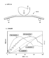
- FIG. 2 is a diagram for explaining the results of examining the characteristics of load and EA amount (energy absorption amount) using the vehicle bumper reinforcement of FIG. 1 and a comparative product
- (a) is a diagram explaining the test method
- (b) is It is the figure which showed the test result.
- FIG. 5 is a view showing a test product after the test in FIG. 4 and is a perspective view corresponding to FIGS. 1 (a) and 5 respectively
- (a) is a product of the present invention
- (b) is a comparative product.
- FIG. 6 is a diagram for explaining another embodiment of the present invention, corresponding to FIG. 1, (a) (is a perspective view, (b) is an enlarged view of a section VIIIB -VIIIB in (a) ⁇ , and (c) is (a) It is an enlarged view of a section VIIIC -VIIIC in. It is a figure which shows the bumper reinforcement for vehicles of the Example of FIG. 8, and is a figure corresponding to FIG. 2, (a) is the top view seen from the upper direction in the arrangement
- FIG. 4 is a diagram for explaining another embodiment of the present invention, corresponding to FIG.
- the vehicle bumper reinforcement of the present invention can be applied to a bumper attached to the front side of the vehicle or a bumper attached to the rear side of the vehicle, but it may be applied to only one of them.
- the shape of the bumper reinforcement in the longitudinal direction that is, the shape in plan view as viewed from above the vehicle is, for example, a shape that is smoothly curved so that the central portion protrudes outward (forward or backward) of the vehicle.
- the shape may be substantially linear, and various modes such as inclining or curving only both end portions toward the vehicle body are possible.
- the plurality of low-strength portions are provided, for example, at two locations that are symmetric with respect to the center in the vehicle width direction, but are separated from the center, but may be provided at four or more locations.
- the low-strength part is desirably provided so that the shape changes smoothly from the general part so that stress concentration does not occur at the boundary with the general part other than the low-strength part. Be made. Except for the low-strength portion, the same cross-sectional shape such as an M shape including the support portion may be used, but the support portion may have a different cross-sectional shape.
- the low-strength portion is configured so as to have a cross section of a shallow inverted dish shape (a shape in which the bottom side of the dish protrudes to the outside of the vehicle) that has one protrusion and extends in the vehicle vertical direction as in the second invention, for example.
- the number of protrusions may be the same as that of the general part, and the protrusion dimension of the protrusions may be reduced to widen the vehicle in the vertical direction.
- the cross-sectional lengths of the general part and the low-strength part in the vertical direction of the vehicle are substantially the same. However, when the first invention is implemented, the cross-sectional lengths of the general part and the low-strength part in the vertical direction of the vehicle.
- the protrusions of the protrusions in the general part and the low-strength part are the same, but various aspects are possible, such as the protrusion dimension of the protrusion of the low-strength part being smaller than the general part. is there.
- the low-strength portion is provided by being widened upward or downward in the vehicle vertical direction, but the low-strength portion can also be provided by being widened upward and downward in the vehicle vertical direction.
- the boarding / sinking prevention function by the low-strength part is not necessarily required to obtain both the boarding prevention and the boarding prevention functions, as long as at least one of the boarding prevention and the boarding prevention functions can be obtained. If the low-strength portion is provided by widening the vehicle in the upward and downward directions in the vehicle vertical direction, it is possible to obtain both the action of preventing the ride and the prevention of the dive.
- the press working for forming the bumper reinforcement may be performed mainly by bending, for example, but may include a drawing element, and a pair of molds having a molding surface having a desired cross-sectional shape. It is desirable to form by one-time press working using. Flat flanges may be provided on both sides of the bumper reinforcement in the vertical direction of the vehicle so as to protrude upward and downward as necessary.
- a steel plate for hot press forming that can be hardened by hot press forming is suitably used.
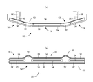
- FIGS. 2A and 2B are views showing the bumper reinforcement 10, in which FIG. 2A is a plan view seen from above in the state of being installed in the vehicle, and FIG. FIG. 3 is a plan view showing a rectangular metal plate 12 that is a material of the bumper reinforcement 10.
- the metal plate is bent into a predetermined shape by hot press forming and has a tensile strength of 1400 MPa by quench hardening. A steel sheet for hot press forming that is increased in strength to the above is used.
- the bumper reinforcement 10 has a long longitudinal shape in the vehicle width direction, which is the left-right direction of FIG. 2 (a), and is located at the center in the vehicle width direction in the plan view shown in FIG. 2 (a). And a pair of inclined portions 16 positioned at both ends, and a pair of curved portions 18 that smoothly connect the linear portions 14 and the inclined portions 16 to each other.
- the bumper reinforcement 10 is configured to be bilaterally symmetrical with respect to the center in the vehicle width direction, and a pair of inclined portions 16 at both ends are portions that retreat to the vehicle body side, and are vehicle body side members via a bumper stay 20.
- the left and right side members 22 are fixed.
- a portion fixed to the middle bumper stay 20 of the inclined portion 16 corresponds to a support portion.
- a bumper body 24 made of synthetic resin is disposed outside the bumper reinforcement 10.
- the straight portion 14 and the pair of inclined portions 16 are a pair of projecting portions 30 that project in an inverted U shape toward the outside of the vehicle (forward in this embodiment) as shown in FIG. , 32 are provided to be separated from each other in the vertical direction of the vehicle via the connecting portion 34 and have an M-shaped cross-sectional shape as a whole, and are flat at both ends thereof, that is, the vertical side portions in the vertical direction of the vehicle.
- the flanges 36 and 38 are provided so as to protrude vertically.
- Each bent portion of the M-shaped cross section is bent so as to be relatively square, and the pair of projecting portions 30 and 32 each have a trapezoidal shape with a narrower width on the tip side.
- connecting portion 34 is a straight line, that is, a flat surface, and is positioned in a plane common to the flanges 36 and 38, and is arranged in a posture in which they are substantially vertical.
- the left direction of FIG.1 (b) bag is a vehicle front side.
- the pair of curved portions 18 of the bumper reinforcement 10 are provided at two symmetrical positions with respect to the center in the vehicle width direction, and as is clear from the cross section in the vehicle vertical direction shown in FIG.
- One protrusion 40 is used.
- the projecting dimension of the projecting part 40 toward the front of the vehicle is the same as that of the projecting parts 30 and 32, but the width dimension in the vertical direction of the vehicle is large, and a shallow inverted dish shape in the cross section in the vertical direction of the vehicle shown in FIG. Is made.
- the vertical dimension of the curved portion 18 is larger than that of the linear portion 14 and the inclined portion 16 and widens upward and downward in the vehicle vertical direction, but from FIGS.
- the straight portions 14 and the inclined portions 16 are smoothly bulged upward and downward in a circular arc shape so as to be smoothly connected to the upper and lower edges.
- the cross-sectional lengths of the cross-sectional shapes in the vehicle vertical direction shown in (b) b and (c) ⁇ in FIG. 1 are substantially the same, and as shown in FIG. 3, the material width dimension in the vehicle vertical direction (the vertical dimension in FIG. 3).
- the flanges 36 and 38 are provided continuously from the linear portion 14 and the inclined portion 16 at both upper and lower ends of the bending portion 18.
- the curved portion 18 constituted by a single projecting portion 40 is a low-strength portion, and the straight portion 14 and the inclined portion 16 having a pair of projecting portions 30 and 32 correspond to a general portion.
- the center line S of (b) and (c) in FIG. 1 is the vertical center line of the straight portion 14 and the inclined portion 16 shown in (b), and (c) the curved portion 18 of the heel is substantially even in the vertical direction. Widened.
- the bending portion 18 is configured by the single protrusion 40, so that the strength against the collision load from the protrusion direction (front of the vehicle) of the protrusion 40 is reduced, and the vehicle is widened in the vertical direction of the vehicle.
- the curved portion 18 can provide a function of preventing the vehicle from getting on and getting into the vehicle, and can prevent the vehicle from getting on and getting into the vehicle without increasing the number of parts and weight.
- the vehicle since the vehicle is widened upward and downward in the vertical direction of the vehicle, both the effects of preventing the vehicle from getting on and preventing the vehicle from getting into the vehicle can be appropriately obtained.
- the straight portion 14 and the inclined portion 16 excluding the low-strength curved portion 18 are provided with a pair of projecting portions 30 and 32 and the cross section is M-shaped, whereas the curved portion 18 is composed of a single projecting portion 40, and has a shallow inverted dish-shaped cross section extending in the vehicle vertical direction, so that the strength of the curved portion 18 against a collision load is a straight portion 14 and an inclined portion. Compared to 16, it is lowered appropriately.
- the metal plate 12 having a constant material width dimension in the vehicle vertical direction is used. Can be pressed, and the material yield is improved and the manufacturing cost is reduced.
- FIG. 4 is a diagram for explaining the results of examining the difference in the collision energy absorption performance using the bumper reinforcement 10 of this example and the comparative product 50 shown in FIG.
- the curved portion 52 has the same cross-sectional shape as the straight portion 14 and the inclined portion 16, and has an M-shaped cross section as shown in FIG.
- FIG. 4 (a) is a view for explaining the test method, in which the vicinity of the support portion of the inclined portion 16 is placed and fixed on a pair of support bases 60, and a collision piece 62 whose tip is a semicircular arc is fixed at a predetermined speed.
- the EA amount energy absorption amount
- the amount of EA corresponds to the integrated value of the load.
- (B) in FIG. 4 is a test result, which is indicated by a solid line when the product of the present invention (bumper reinforcement 10), that is, with a low-strength portion, and indicated by a broken line when a comparative product 50, that is, without a low-strength portion.
- FIG. 6 is a perspective view of the test product after the test.
- (A) is the product of the present invention (bumper reinforcement 10)
- (b) is the comparative product 50
- the comparative product 50 is a straight line portion that is a load input portion.
- the bent portion 18 is deformed in the opposite direction in the product of the present invention, whereas the straight portion 14 is only gently bent without buckling.
- FIG. 7 is a cross-sectional view corresponding to FIG.
- the curved portion 92 of the vehicular bumper reinforcement 90 shown in FIGS. 10 and 11 is widened only in the downward direction, contrary to the curved portion 82, and the action of preventing the vehicle from getting into the front vehicle is not obtained. Since the downward projecting dimension is larger than that of the curved portion 18, it is possible to more appropriately obtain a ride-up preventing action for the preceding vehicle, and for example, it is positively applied to a vehicle having a high bumper position. 10 and 11 correspond to FIGS. 1 and 2 described above.
- Bumper reinforcement for vehicle 12 Metal plate material 14: Straight part (support part, general part) 16: Inclined part (general part) 18, 70, 82, 92: Curved part (low strength part) 30 , 32, 40, 72, 74: protrusion
Abstract
Without inviting an increased weight or number of parts, this vehicle bumper reinforcement can obtain excellent impact energy absorption performance and can prevent the vehicle from driving up onto or slipping under another vehicle. Because low-strength curved portions (18) are provided in two places symmetrically with respect to the center in the vehicle width direction, the curved portions (18) are easily deformed, and by suppressing the immediate lowering of the load due to buckling at the position where the load is applied, excellent impact energy absorption performance can be obtained. In that case, the curved portions (18), by being configured by single protrusions (40), have lowered strength against collision loads from the protrusion direction (the front of the vehicle), and, having increased width at the top and bottom in the vertical direction of the vehicle, the curved portion (18) can prevent the vehicle from driving up onto or slipping under another vehicle, and make it possible to suppress the vehicle from driving up onto or slipping under a another vehicle, without inviting an increased weight or number of parts.
Description
本発明は車両用バンパーリインフォースメントに係り、特に、車両の乗り上げ・潜り込み防止機能を有するバンパーリインフォースメントの改良に関するものである。
The present invention relates to a bumper reinforcement for a vehicle, and more particularly to an improvement of a bumper reinforcement having a function of preventing the vehicle from getting on and getting into the vehicle.
金属板材にて構成されているとともに、車両上下方向に隔てて車両外側へ突き出す複数の突出部を有するようにプレス加工された車幅方向に長い長手形状の車両用バンパーリインフォースメントが提案されている。特許文献1に記載の装置はその一例で、熱間プレス成形(ホットスタンピング成形)により引張強度が高い高強度のバンパーリインフォースメントが得られるようになっている。特許文献2には、熱間プレス成形により焼入れ硬化させる場合に、荷重入力部位の座屈(折れ曲がり)で荷重が一気に低下することを防止するため、局部的に焼入れが緩和された低強度部を設け、荷重の急低下を抑制して優れた衝突エネルギー吸収性能が得られるようにする技術が提案されている。また、特許文献3には、車両の潜り込みを防止するための嵩上げ壁をバンパーリインフォースメントに一体的に固設する技術が提案されている。
A vehicular bumper reinforcement having a long longitudinal shape in the vehicle width direction, which is made of a metal plate and is press-processed so as to have a plurality of protrusions protruding outward from the vehicle in the vertical direction of the vehicle, has been proposed. . The apparatus described in Patent Document 1 is one example, and high strength bumper reinforcement having high tensile strength can be obtained by hot press molding (hot stamping molding). In Patent Document 2, when quenching and hardening by hot press molding, in order to prevent a load from being lowered at a stretch due to buckling (bending) of a load input portion, a low-strength portion whose quenching is locally relaxed is provided. There has been proposed a technique for providing an excellent collision energy absorption performance by suppressing a sudden drop in load. Patent Document 3 proposes a technique in which a raised wall for preventing a vehicle from getting in is integrally fixed to a bumper reinforcement.
したがって、引用文献2に記載の技術を引用文献1に適用することにより、優れた衝突エネルギー吸収性能が得られるようにできるが、車両の乗り上げや潜り込みを防止する機能は得られず、引用文献3のように別部材を固設すると、部品点数や重量の増加を招いて必ずしも十分に満足できないという問題があった。
Therefore, by applying the technique described in the cited document 2 to the cited document 1, it is possible to obtain an excellent collision energy absorption performance, but a function for preventing the vehicle from getting on and entering the vehicle cannot be obtained. If another member is fixed as described above, there is a problem that the number of parts and the weight are increased, which is not always satisfactory.
本発明は以上の事情を背景として為されたもので、その目的とするところは、優れた衝突エネルギー吸収性能が得られるとともに、部品点数や重量の増加を招くことなく車両の乗り上げ・潜り込み防止機能が得られるようにすることにある。
The present invention has been made against the background of the above circumstances, and its purpose is to provide excellent collision energy absorption performance, and to prevent the vehicle from getting on and getting into the vehicle without increasing the number of parts and weight. Is to be obtained.
かかる目的を達成するために、第1発明は、金属板材にて構成されているとともに、車両上下方向に隔てて車両外側へ突き出す複数の突出部を有するようにプレス加工された車幅方向に長い長手形状の車両用バンパーリインフォースメントであって、車幅方向において車体に固定される一対の支持部よりも内側であって車幅方向の中心に対して対称的な複数箇所に、車両上下方向へ拡幅されるとともに、前記突出部の数が少ないかその突出部の突出寸法が小さくされた低強度部が設けられていることを特徴とする。
In order to achieve such an object, the first invention is constituted by a metal plate material and is long in the vehicle width direction press-processed so as to have a plurality of projecting portions projecting outward from the vehicle with an interval in the vehicle vertical direction. Longitudinal bumper reinforcement for a vehicle, which is inside a pair of support portions fixed to the vehicle body in the vehicle width direction and symmetrical with respect to the center in the vehicle width direction, in the vehicle vertical direction A low-strength portion is provided which is widened and has a small number of protrusions or a small protrusion dimension of the protrusions.
第2発明は、第1発明の車両用バンパーリインフォースメントにおいて、(a) 前記低強度部を除く一般部は、前記突出部が一対設けられて車両上下方向の断面がM字形状を成している一方、(b) 前記低強度部は、前記突出部の突出寸法は前記一般部と同じであるが数が一つで、車両上下方向に延びた浅い逆皿形状の断面を有しており、(c) 前記一般部および前記低強度部の車両上下方向の断面長さは略同じであることを特徴とする。
According to a second aspect of the present invention, in the bumper reinforcement for a vehicle according to the first aspect of the invention, (a) a general portion excluding the low-strength portion is provided with a pair of the protruding portions, and the vehicle vertical section has an M-shaped cross section. On the other hand, (b) The low-strength part has a shallow inverted dish-shaped cross section that extends in the vehicle vertical direction with the same number of protrusions as the general part but the number of protrusions of the protrusion is one. (C) The cross-sectional lengths of the general portion and the low-strength portion in the vehicle vertical direction are substantially the same.
第3発明は、第1発明または第2発明の車両用バンパーリインフォースメントにおいて、前記低強度部は、車両上下方向の上方または下方へ拡幅されていることを特徴とする。
The third invention is characterized in that in the vehicle bumper reinforcement of the first invention or the second invention, the low-strength portion is widened upward or downward in the vehicle vertical direction.
このような車両用バンパーリインフォースメントにおいては、一対の支持部よりも内側であって車幅方向の中心に対して対称的な複数箇所に低強度部が設けられているため、その低強度部で変形し易くなり、荷重入力部位の座屈で荷重が一気に低下することが抑制されて、優れた衝突エネルギー吸収性能が得られるようになる。その場合に、本発明の低強度部は、突出部の数が少ないかその突出部の突出寸法が小さくされることで、その突出部の突出方向からの衝突荷重に対する強度が低下させられ、車両上下方向へ拡幅されているため、その低強度部によって乗り上げ・潜り込み防止機能が得られるようになり、部品点数や重量の増加を招くことなく車両の乗り上げや潜り込みを抑制できる。
In such a vehicle bumper reinforcement, since the low-strength portions are provided at a plurality of positions inside the pair of support portions and symmetrical with respect to the center in the vehicle width direction, It becomes easy to deform | transform, it is suppressed that a load falls at a stretch by buckling of a load input site | part, and the outstanding collision energy absorption performance comes to be obtained. In that case, the strength of the low strength portion of the present invention with respect to the collision load from the protruding direction of the protruding portion is reduced by reducing the number of protruding portions or reducing the protruding size of the protruding portion. Since it is widened in the vertical direction, the low-strength portion can provide a function for preventing the vehicle from getting in and getting in, and the vehicle can be prevented from getting in and getting in without increasing the number of parts and weight.
第2発明では、低強度部を除く一般部は突出部が一対設けられて断面がM字形状を成しているのに対し、低強度部は突出部が一つで車両上下方向に延びた浅い逆皿形状の断面を有しているため、その低強度部の衝突荷重に対する強度が一般部に比較して適切に低下させられる。また、それ等の一般部および低強度部の車両上下方向の断面長さは略同じであるため、車両上下方向の素材幅寸法が一定の金属板材を用いてプレス加工することが可能で、材料歩留りが向上して製造コストが低減される。
In the second invention, the general part except the low-strength part is provided with a pair of protrusions and has an M-shaped cross section, whereas the low-strength part has one protrusion and extends in the vehicle vertical direction. Since it has a shallow inverted dish-shaped cross section, the strength of the low-strength portion against a collision load can be appropriately reduced as compared with the general portion. In addition, since the cross-sectional lengths of the general part and the low-strength part in the vertical direction of the vehicle are substantially the same, it is possible to press using a metal plate material having a constant material width dimension in the vertical direction of the vehicle. The yield is improved and the manufacturing cost is reduced.
本発明の車両用バンパーリインフォースメントは、車両前側に取り付けられるバンパーにも車両後側に取り付けられるバンパーにも適用され得るが、何れか一方のみに適用するだけでも差し支えない。
The vehicle bumper reinforcement of the present invention can be applied to a bumper attached to the front side of the vehicle or a bumper attached to the rear side of the vehicle, but it may be applied to only one of them.
また、バンパーリインフォースメントの長手方向の形状、すなわち車両の上方から見た平面視の形状は、例えば中央部が車両の外方向(前方または後方)へ突き出すように滑らかに湾曲した形状とされるが、略直線状であっても良いし、両端部のみ車体側へ傾斜させたり湾曲させたりするなど、種々の態様が可能である。
In addition, the shape of the bumper reinforcement in the longitudinal direction, that is, the shape in plan view as viewed from above the vehicle is, for example, a shape that is smoothly curved so that the central portion protrudes outward (forward or backward) of the vehicle. The shape may be substantially linear, and various modes such as inclining or curving only both end portions toward the vehicle body are possible.
複数の低強度部は、例えば車幅方向の中心に対して対称的な2箇所に中心から離間して設けられるが、4箇所以上に設けることも可能である。この低強度部は、低強度部以外の一般部との境界で応力集中が生じないように、一般部から滑らかに形状変化するように設けることが望ましく、例えば車両上下方向へ円弧状に膨出させられる。低強度部以外は、支持部を含めてM字形状等の同一断面形状であっても良いが、支持部では異なる断面形状とすることもできる。
The plurality of low-strength portions are provided, for example, at two locations that are symmetric with respect to the center in the vehicle width direction, but are separated from the center, but may be provided at four or more locations. The low-strength part is desirably provided so that the shape changes smoothly from the general part so that stress concentration does not occur at the boundary with the general part other than the low-strength part. Be made. Except for the low-strength portion, the same cross-sectional shape such as an M shape including the support portion may be used, but the support portion may have a different cross-sectional shape.
低強度部は、例えば第2発明のように突出部が一つで車両上下方向に延びた浅い逆皿形状(皿の底部側が車両外側へ突き出す形状)の断面を有するように構成されるが、突出部の数は一般部と同じで、突出部の突出寸法を小さくして車両上下方向へ拡幅するようにしても良い。また、第2発明では、一般部および低強度部の車両上下方向の断面長さが略同じであるが、第1発明の実施に際しては、一般部および低強度部の車両上下方向の断面長さが同じである必要はなく、適宜定められる。第2発明ではまた、一般部および低強度部における突出部の突出寸法が同じであるが、低強度部の突出部の突出寸法を一般部より小さくすることもできるなど、種々の態様が可能である。
The low-strength portion is configured so as to have a cross section of a shallow inverted dish shape (a shape in which the bottom side of the dish protrudes to the outside of the vehicle) that has one protrusion and extends in the vehicle vertical direction as in the second invention, for example. The number of protrusions may be the same as that of the general part, and the protrusion dimension of the protrusions may be reduced to widen the vehicle in the vertical direction. In the second invention, the cross-sectional lengths of the general part and the low-strength part in the vertical direction of the vehicle are substantially the same. However, when the first invention is implemented, the cross-sectional lengths of the general part and the low-strength part in the vertical direction of the vehicle. Need not be the same, and are determined as appropriate. In the second invention, the protrusions of the protrusions in the general part and the low-strength part are the same, but various aspects are possible, such as the protrusion dimension of the protrusion of the low-strength part being smaller than the general part. is there.
第3発明では、車両上下方向の上方または下方へ拡幅されて低強度部が設けられているが、車両上下方向の上方および下方へそれぞれ拡幅して低強度部を設けることもできる。低強度部による乗り上げ・潜り込み防止機能は、必ずしも乗り上げ防止および潜り込み防止の両方の作用が得られる必要はなく、乗り上げ防止および潜り込み防止の少なくとも一方の作用が得られれば良い。車両上下方向の上方および下方へそれぞれ拡幅して低強度部を設ければ、乗り上げ防止および潜り込み防止の両方の作用が得られる。
In the third aspect of the invention, the low-strength portion is provided by being widened upward or downward in the vehicle vertical direction, but the low-strength portion can also be provided by being widened upward and downward in the vehicle vertical direction. The boarding / sinking prevention function by the low-strength part is not necessarily required to obtain both the boarding prevention and the boarding prevention functions, as long as at least one of the boarding prevention and the boarding prevention functions can be obtained. If the low-strength portion is provided by widening the vehicle in the upward and downward directions in the vehicle vertical direction, it is possible to obtain both the action of preventing the ride and the prevention of the dive.
バンパーリインフォースメントを形成するためのプレス加工は、例えば曲げ加工を主体として行われるものでも良いが、絞り加工の要素を含んでいても良く、目的とする断面形状の成形面を有する一対の金型を用いて1回のプレス加工で形成することが望ましい。バンパーリインフォースメントの車両上下方向の両側部には、必要に応じて平坦なフランジが車両の上方側および下方側へ突き出すように設けられても良い。金属板材としては、熱間プレス成形により焼入れ硬化させることができる熱間プレス成形用鋼板が好適に用いられる。
The press working for forming the bumper reinforcement may be performed mainly by bending, for example, but may include a drawing element, and a pair of molds having a molding surface having a desired cross-sectional shape. It is desirable to form by one-time press working using. Flat flanges may be provided on both sides of the bumper reinforcement in the vertical direction of the vehicle so as to protrude upward and downward as necessary. As the metal plate material, a steel plate for hot press forming that can be hardened by hot press forming is suitably used.
以下、本発明の実施例を、図面を参照しつつ詳細に説明する。
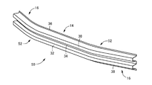
図1の車両用バンパーリインフォースメント(以下、単にバンパーリインフォースメントともいう)10は、車両のフロント側に配設されるもので、(a) は斜視図、(b) は(a) におけるIB-IB断面の拡大図、(c) は(a) におけるIC-IC断面の拡大図である。図2は、同じくバンパーリインフォースメント10を示す図で、(a) は車両への配設状態において上方から見た平面図、(b) は車両の前側から見た正面図である。また、図3は、バンパーリインフォースメント10の素材である長方形の金属板材12を示す平面図で、本実施例では熱間プレス成形により所定形状に曲げ加工されるとともに、焼入れ硬化により引張強度が1400MPa以上まで高強度化される熱間プレス成形用鋼板が用いられる。 Hereinafter, embodiments of the present invention will be described in detail with reference to the drawings.
The vehicle bumper reinforcement (hereinafter also simply referred to as bumper reinforcement) 10 in FIG. 1 is disposed on the front side of the vehicle, (a) is a perspective view, and (b) is an IB- IB cross section enlarged view, (c) is an IC-IC cross section enlarged view of (a). FIGS. 2A and 2B are views showing thebumper reinforcement 10, in which FIG. 2A is a plan view seen from above in the state of being installed in the vehicle, and FIG. FIG. 3 is a plan view showing a rectangular metal plate 12 that is a material of the bumper reinforcement 10. In this embodiment, the metal plate is bent into a predetermined shape by hot press forming and has a tensile strength of 1400 MPa by quench hardening. A steel sheet for hot press forming that is increased in strength to the above is used.
図1の車両用バンパーリインフォースメント(以下、単にバンパーリインフォースメントともいう)10は、車両のフロント側に配設されるもので、(a) は斜視図、(b) は(a) におけるIB-IB断面の拡大図、(c) は(a) におけるIC-IC断面の拡大図である。図2は、同じくバンパーリインフォースメント10を示す図で、(a) は車両への配設状態において上方から見た平面図、(b) は車両の前側から見た正面図である。また、図3は、バンパーリインフォースメント10の素材である長方形の金属板材12を示す平面図で、本実施例では熱間プレス成形により所定形状に曲げ加工されるとともに、焼入れ硬化により引張強度が1400MPa以上まで高強度化される熱間プレス成形用鋼板が用いられる。 Hereinafter, embodiments of the present invention will be described in detail with reference to the drawings.
The vehicle bumper reinforcement (hereinafter also simply referred to as bumper reinforcement) 10 in FIG. 1 is disposed on the front side of the vehicle, (a) is a perspective view, and (b) is an IB- IB cross section enlarged view, (c) is an IC-IC cross section enlarged view of (a). FIGS. 2A and 2B are views showing the
バンパーリインフォースメント10は、図2(a) の左右方向である車幅方向に長い長手形状を成しているとともに、図2の(a) に示す平面視において、車幅方向の中央部分に位置する直線部14と、両端部に位置する一対の傾斜部16と、それ等の直線部14および傾斜部16を滑らかに接続する一対の湾曲部18とを備えている。このバンパーリインフォースメント10は、車幅方向の中心に対して左右対称に構成されており、両端の一対の傾斜部16は車体側へ後退する部分で、バンパーステイ20を介して車体側部材である左右のサイドメンバ22に固定される。傾斜部16の中バンパーステイ20に固定される部分が支持部に相当する。そして、このようなバンパーリインフォースメント10の外側には、合成樹脂製のバンパー本体24が配設される。
The bumper reinforcement 10 has a long longitudinal shape in the vehicle width direction, which is the left-right direction of FIG. 2 (a), and is located at the center in the vehicle width direction in the plan view shown in FIG. 2 (a). And a pair of inclined portions 16 positioned at both ends, and a pair of curved portions 18 that smoothly connect the linear portions 14 and the inclined portions 16 to each other. The bumper reinforcement 10 is configured to be bilaterally symmetrical with respect to the center in the vehicle width direction, and a pair of inclined portions 16 at both ends are portions that retreat to the vehicle body side, and are vehicle body side members via a bumper stay 20. The left and right side members 22 are fixed. A portion fixed to the middle bumper stay 20 of the inclined portion 16 corresponds to a support portion. A bumper body 24 made of synthetic resin is disposed outside the bumper reinforcement 10.
上記バンパーリインフォースメント10の中、直線部14および一対の傾斜部16は、図1の(b) に示すように車両外側(この実施例では前方)へ逆U字形状に突き出す一対の突出部30、32が連結部34を介して車両上下方向に隔てて設けられ、全体としてM字型断面形状を成しているとともに、その両端部、すなわち車両上下方向の上下の側部には、それぞれ平坦なフランジ36、38が上下に突き出すように設けられている。M字型断面の各折れ曲がり部分は、何れも比較的角張るように曲げ加工されており、一対の突出部30、32は、それぞれ先端側程幅寸法が狭くなる台形状を成している。また、連結部34は一直線すなわち平坦面で、フランジ36、38と共通の平面内に位置させられ、それ等が略垂直となる姿勢で配設される。なお、図1(b) の左方向が車両前側である。
In the bumper reinforcement 10, the straight portion 14 and the pair of inclined portions 16 are a pair of projecting portions 30 that project in an inverted U shape toward the outside of the vehicle (forward in this embodiment) as shown in FIG. , 32 are provided to be separated from each other in the vertical direction of the vehicle via the connecting portion 34 and have an M-shaped cross-sectional shape as a whole, and are flat at both ends thereof, that is, the vertical side portions in the vertical direction of the vehicle. The flanges 36 and 38 are provided so as to protrude vertically. Each bent portion of the M-shaped cross section is bent so as to be relatively square, and the pair of projecting portions 30 and 32 each have a trapezoidal shape with a narrower width on the tip side. Further, the connecting portion 34 is a straight line, that is, a flat surface, and is positioned in a plane common to the flanges 36 and 38, and is arranged in a posture in which they are substantially vertical. In addition, the left direction of FIG.1 (b) bag is a vehicle front side.
バンパーリインフォースメント10の一対の湾曲部18は、車幅方向の中心に対して対称的な2位置に設けられているとともに、図1(c) に示す車両上下方向の断面から明らかなように単一の突出部40にて構成されている。この突出部40の車両前方への突出寸法は前記突出部30、32と同じであるが、車両上下方向の幅寸法が大きく、図1(c) に示す車両上下方向の断面において浅い逆皿形状を成している。すなわち、この湾曲部18の上下方向寸法は前記直線部14や傾斜部16よりも大きく、車両上下方向の上方および下方へそれぞれ拡幅しているが、図1(a) および図2(b) から明らかなように、それ等の直線部14および傾斜部16の上下の端縁に滑らかに接続されるように、上方および下方へそれぞれ滑らかに円弧状に膨出させられている。図1の(b) および(c) に示す車両上下方向の断面形状における断面長さは略同じで、図3に示すように車両上下方向の素材幅寸法(図3における上下方向の幅寸法)が一定の長方形の金属板材12をプレス加工することによって製造できる。また、上記湾曲部18の上下の両端には、前記フランジ36、38が前記直線部14、傾斜部16から連続して設けられている。本実施例では、単一の突出部40にて構成されている湾曲部18が低強度部で、一対の突出部30、32を有する直線部14および傾斜部16が一般部に相当する。図1の(b) および(c) の中心線Sは、(b) に示す直線部14および傾斜部16における上下方向の中心線で、(c) の湾曲部18は上下方向へ略均等に拡幅されている。
The pair of curved portions 18 of the bumper reinforcement 10 are provided at two symmetrical positions with respect to the center in the vehicle width direction, and as is clear from the cross section in the vehicle vertical direction shown in FIG. One protrusion 40 is used. The projecting dimension of the projecting part 40 toward the front of the vehicle is the same as that of the projecting parts 30 and 32, but the width dimension in the vertical direction of the vehicle is large, and a shallow inverted dish shape in the cross section in the vertical direction of the vehicle shown in FIG. Is made. In other words, the vertical dimension of the curved portion 18 is larger than that of the linear portion 14 and the inclined portion 16 and widens upward and downward in the vehicle vertical direction, but from FIGS. 1 (a) and 2 (b) As can be seen, the straight portions 14 and the inclined portions 16 are smoothly bulged upward and downward in a circular arc shape so as to be smoothly connected to the upper and lower edges. The cross-sectional lengths of the cross-sectional shapes in the vehicle vertical direction shown in (b) b and (c) の in FIG. 1 are substantially the same, and as shown in FIG. 3, the material width dimension in the vehicle vertical direction (the vertical dimension in FIG. 3). Can be manufactured by pressing a rectangular metal plate 12 having a constant width. Further, the flanges 36 and 38 are provided continuously from the linear portion 14 and the inclined portion 16 at both upper and lower ends of the bending portion 18. In this embodiment, the curved portion 18 constituted by a single projecting portion 40 is a low-strength portion, and the straight portion 14 and the inclined portion 16 having a pair of projecting portions 30 and 32 correspond to a general portion. The center line S of (b) and (c) in FIG. 1 is the vertical center line of the straight portion 14 and the inclined portion 16 shown in (b), and (c) the curved portion 18 of the heel is substantially even in the vertical direction. Widened.
このような本実施例の車両用バンパーリインフォースメント10においては、車幅方向の中心に対して対称的な2箇所に低強度の湾曲部18が設けられているため、その湾曲部18で変形し易くなり、荷重入力部位の座屈で荷重が一気に低下することが抑制されて、優れた衝突エネルギー吸収性能が得られるようになる。その場合に、湾曲部18は、単一の突出部40にて構成されることにより、その突出部40の突出方向(車両前方)からの衝突荷重に対する強度が低下させられ、車両上下方向へ拡幅されているため、その湾曲部18によって車両の乗り上げ・潜り込み防止機能が得られるようになり、部品点数や重量の増加を招くことなく車両の乗り上げや潜り込みを抑制できる。本実施例では車両上下方向の上方および下方へそれぞれ拡幅されているため、車両の乗り上げ防止および潜り込み防止の両方の作用が適切に得られる。
In such a vehicle bumper reinforcement 10 of this embodiment, since the low-strength curved portions 18 are provided at two symmetrical positions with respect to the center in the vehicle width direction, the curved portion 18 is deformed. It becomes easy, and it is suppressed that a load falls at a stretch by buckling of a load input site | part, and the outstanding collision energy absorption performance comes to be obtained. In this case, the bending portion 18 is configured by the single protrusion 40, so that the strength against the collision load from the protrusion direction (front of the vehicle) of the protrusion 40 is reduced, and the vehicle is widened in the vertical direction of the vehicle. Therefore, the curved portion 18 can provide a function of preventing the vehicle from getting on and getting into the vehicle, and can prevent the vehicle from getting on and getting into the vehicle without increasing the number of parts and weight. In this embodiment, since the vehicle is widened upward and downward in the vertical direction of the vehicle, both the effects of preventing the vehicle from getting on and preventing the vehicle from getting into the vehicle can be appropriately obtained.
また、本実施例では、低強度の湾曲部18を除く直線部14および傾斜部16では一対の突出部30、32が設けられて断面がM字形状を成しているのに対し、湾曲部18は単一の突出部40にて構成されており、車両上下方向に延びた浅い逆皿形状の断面を有しているため、その湾曲部18の衝突荷重に対する強度が直線部14および傾斜部16にに比較して適切に低下させられる。
In the present embodiment, the straight portion 14 and the inclined portion 16 excluding the low-strength curved portion 18 are provided with a pair of projecting portions 30 and 32 and the cross section is M-shaped, whereas the curved portion 18 is composed of a single projecting portion 40, and has a shallow inverted dish-shaped cross section extending in the vehicle vertical direction, so that the strength of the curved portion 18 against a collision load is a straight portion 14 and an inclined portion. Compared to 16, it is lowered appropriately.
また、本実施例では、上記直線部14、傾斜部16、および湾曲部18の車両上下方向の断面長さが略同じであるため、車両上下方向の素材幅寸法が一定の金属板材12を用いてプレス加工することが可能で、材料歩留りが向上して製造コストが低減される。
Further, in the present embodiment, since the cross-sectional lengths of the straight portion 14, the inclined portion 16, and the curved portion 18 in the vehicle vertical direction are substantially the same, the metal plate 12 having a constant material width dimension in the vehicle vertical direction is used. Can be pressed, and the material yield is improved and the manufacturing cost is reduced.
図4は、本実施例のバンパーリインフォースメント10と図5に示す比較品50とを用いて、衝突エネルギー吸収性能の違いを調べた結果を説明する図である。比較品50は、湾曲部52の断面形状が前記直線部14、傾斜部16と同じで、図1(b) に示すようにM字形断面とされているものである。図4の(a) は試験方法を説明する図で、前記傾斜部16の支持部付近を一対の支持台60上に載置して固定し、先端が半円弧形状の衝突片62を所定速度で車幅方向の中央部分に衝突させ、その時の荷重変化を測定してEA量(エネルギー吸収量)を求めた。EA量は荷重の積分値に相当する。
FIG. 4 is a diagram for explaining the results of examining the difference in the collision energy absorption performance using the bumper reinforcement 10 of this example and the comparative product 50 shown in FIG. In the comparative product 50, the curved portion 52 has the same cross-sectional shape as the straight portion 14 and the inclined portion 16, and has an M-shaped cross section as shown in FIG. FIG. 4 (a) is a view for explaining the test method, in which the vicinity of the support portion of the inclined portion 16 is placed and fixed on a pair of support bases 60, and a collision piece 62 whose tip is a semicircular arc is fixed at a predetermined speed. The EA amount (energy absorption amount) was obtained by making the vehicle collide with the center portion in the vehicle width direction and measuring the load change at that time. The amount of EA corresponds to the integrated value of the load.
図4の(b) は試験結果で、本発明品(バンパーリインフォースメント10)すなわち低強度部有りの場合は実線で示し、比較品50すなわち低強度部無しの場合は破線で示した。この結果から、低強度部無しの比較品50の場合、強度が高いことから荷重が急激に立ち上がるが、車幅方向の中央の荷重入力部で座屈(折れ曲がり)し始める変位70mm付近から荷重が急に低下してEA量の伸びが鈍くなる。これに対し、低強度部有りの本発明品は、低強度の湾曲部18を有するため、その湾曲部18が変形することにより荷重の立ち上がりが緩やかになるが、荷重のピークはなだらかで比較的長く、滑らかな荷重特性になるとともに、最終的なEA量は比較品50と同程度以上で、優れた衝突エネルギー吸収性能が得られる。また、図6は試験後の試験品の斜視図で、(a) は本発明品(バンパーリインフォースメント10)、(b) は比較品50であり、比較品50は荷重入力部である直線部14の中央付近で座屈しているのに対し、本発明品は、湾曲部18が逆向きに変形しているものの、直線部14は座屈することなく緩やかに湾曲しているだけであった。
(B) in FIG. 4 is a test result, which is indicated by a solid line when the product of the present invention (bumper reinforcement 10), that is, with a low-strength portion, and indicated by a broken line when a comparative product 50, that is, without a low-strength portion. From this result, in the case of the comparative product 50 without the low-strength portion, the load suddenly rises because of the high strength, but the load starts from around 70 mm displacement where the load input portion in the center in the vehicle width direction starts buckling (bending). It suddenly decreases and the growth of the EA amount becomes dull. On the other hand, the product according to the present invention having the low strength portion has the low strength curved portion 18, so that the rising of the load becomes gentle when the curved portion 18 is deformed, but the load peak is gentle and relatively Long and smooth load characteristics are obtained, and the final EA amount is about the same as or higher than that of the comparative product 50, and excellent impact energy absorption performance is obtained. FIG. 6 is a perspective view of the test product after the test. (A) is the product of the present invention (bumper reinforcement 10), (b) is the comparative product 50, and the comparative product 50 is a straight line portion that is a load input portion. In contrast, the bent portion 18 is deformed in the opposite direction in the product of the present invention, whereas the straight portion 14 is only gently bent without buckling.
次に、本発明の他の実施例を説明する。なお、以下の実施例において前記実施例と実質的に共通する部分には同一の符号を付して詳しい説明を省略する。
Next, another embodiment of the present invention will be described. In the following embodiments, parts that are substantially the same as those in the above embodiments are denoted by the same reference numerals, and detailed description thereof is omitted.
前記実施例の湾曲部18は単一の突出部40にて構成されていたが、図7に示す湾曲部70のように、一対の突出部72、74を比較的浅い連結部76によって連結した場合も、前記直線部14、傾斜部16に比較して車両前方からの衝突荷重に対する強度が低くなり、低強度部として用いることができる。図7は前記図1の(c) に対応する断面図である。
Although the bending portion 18 of the above-described embodiment is configured by a single protrusion 40, a pair of protrusions 72 and 74 are connected by a relatively shallow connecting portion 76 as in the bending portion 70 shown in FIG. Also in this case, the strength against the collision load from the front of the vehicle is lower than that of the straight portion 14 and the inclined portion 16, and can be used as a low strength portion. FIG. 7 is a cross-sectional view corresponding to FIG.
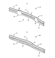
また、図8および図9に示す車両用バンパーリインフォースメント80の湾曲部82は、図8(c) に示す断面形状そのものは前記湾曲部18と同じであるが、上方側へのみ拡幅されている点が相違する。この場合は、前方車両への乗り上げ防止作用は得られないものの、上方への突出寸法は湾曲部18よりも大きいため、前方車両に対する潜り込み防止作用が一層適切に得られるようになり、例えばバンパー位置が低い車両に積極的に適用される。図8および図9は前記図1および図2に対応する図である。
8 and 9 has the same sectional shape as that of the curved portion 18 shown in FIG. 8 (c), but is widened only upward. The point is different. In this case, although it is impossible to prevent the vehicle from getting on the front vehicle, the upward projecting dimension is larger than that of the curved portion 18, so that the operation to prevent the vehicle from getting into the front vehicle can be obtained more appropriately. Actively applied to vehicles with low 8 and 9 correspond to FIGS. 1 and 2 described above.
図10および図11に示す車両用バンパーリインフォースメント90の湾曲部92は、上記湾曲部82とは逆に下方側へのみ拡幅されている場合で、前方車両への潜り込み防止作用は得られないものの、下方への突出寸法は湾曲部18よりも大きいため、前方車両に対する乗り上げ防止作用が一層適切に得られるようになり、例えばバンパー位置が高い車両に積極的に適用される。図10および図11は前記図1および図2に対応する図である。
The curved portion 92 of the vehicular bumper reinforcement 90 shown in FIGS. 10 and 11 is widened only in the downward direction, contrary to the curved portion 82, and the action of preventing the vehicle from getting into the front vehicle is not obtained. Since the downward projecting dimension is larger than that of the curved portion 18, it is possible to more appropriately obtain a ride-up preventing action for the preceding vehicle, and for example, it is positively applied to a vehicle having a high bumper position. 10 and 11 correspond to FIGS. 1 and 2 described above.
以上、本発明の実施例を図面に基づいて詳細に説明したが、これ等はあくまでも一実施形態であり、本発明は当業者の知識に基づいて種々の変更,改良を加えた態様で実施することができる。
As mentioned above, although the Example of this invention was described in detail based on drawing, these are one embodiment to the last, and this invention is implemented in the aspect which added the various change and improvement based on the knowledge of those skilled in the art. be able to.
10、80、90:車両用バンパーリインフォースメント 12:金属板材 14:直線部(支持部、一般部) 16:傾斜部(一般部) 18、70、82、92:湾曲部(低強度部) 30、32、40、72、74:突出部
10, 80, 90: Bumper reinforcement for vehicle 12: Metal plate material 14: Straight part (support part, general part) 16: Inclined part (general part) 18, 70, 82, 92: Curved part (low strength part) 30 , 32, 40, 72, 74: protrusion
Claims (3)
- 金属板材にて構成されているとともに、車両上下方向に隔てて車両外側へ突き出す複数の突出部を有するようにプレス加工された車幅方向に長い長手形状の車両用バンパーリインフォースメントであって、
車幅方向において車体に固定される一対の支持部よりも内側であって車幅方向の中心に対して対称的な複数箇所に、車両上下方向へ拡幅されるとともに、前記突出部の数が少ないか該突出部の突出寸法が小さくされた低強度部が設けられている
ことを特徴とする車両用バンパーリインフォースメント。 A vehicular bumper reinforcement having a long longitudinal shape in the vehicle width direction, which is made of a metal plate and is pressed so as to have a plurality of protrusions protruding to the vehicle outer side in the vehicle vertical direction,
It is widened in the vehicle vertical direction at a plurality of locations inside the pair of support portions fixed to the vehicle body in the vehicle width direction and symmetrical with respect to the center in the vehicle width direction, and the number of the protruding portions is small. A bumper reinforcement for a vehicle, characterized in that a low-strength portion in which the protruding dimension of the protruding portion is reduced is provided. - 前記低強度部を除く一般部は、前記突出部が一対設けられて車両上下方向の断面がM字形状を成している一方、
前記低強度部は、前記突出部の突出寸法は前記一般部と同じであるが数が一つで、車両上下方向に延びた浅い逆皿形状の断面を有しており、
前記一般部および前記低強度部の車両上下方向の断面長さは略同じである
ことを特徴とする請求項1に記載の車両用バンパーリインフォースメント。 While the general part excluding the low-strength part is provided with a pair of the protruding parts and the vehicle vertical cross-section is M-shaped,
The low-strength part has a shallow inverted dish-shaped cross section that extends in the vehicle vertical direction, although the protruding dimension of the protruding part is the same as that of the general part, but the number is one.
The vehicular bumper reinforcement according to claim 1, wherein the general section and the low-strength section have substantially the same cross-sectional length in the vehicle vertical direction. - 前記低強度部は、車両上下方向の上方または下方へ拡幅されている
ことを特徴とする請求項1または2に記載の車両用バンパーリインフォースメント。 The vehicular bumper reinforcement according to claim 1, wherein the low-strength portion is widened upward or downward in the vehicle vertical direction.
Priority Applications (3)
| Application Number | Priority Date | Filing Date | Title |
|---|---|---|---|
| CN201280033716.0A CN103648849B (en) | 2011-07-07 | 2012-04-17 | Bumper reinforcement for vehicles |
| US14/130,430 US9114768B2 (en) | 2011-07-07 | 2012-04-17 | Vehicle bumper reinforcement |
| EP12807205.5A EP2730468A4 (en) | 2011-07-07 | 2012-04-17 | Vehicle bumper reinforcement |
Applications Claiming Priority (2)
| Application Number | Priority Date | Filing Date | Title |
|---|---|---|---|
| JP2011-150617 | 2011-07-07 | ||
| JP2011150617A JP5689034B2 (en) | 2011-07-07 | 2011-07-07 | Bumper reinforcement for vehicles |
Publications (1)
| Publication Number | Publication Date |
|---|---|
| WO2013005465A1 true WO2013005465A1 (en) | 2013-01-10 |
Family
ID=47436824
Family Applications (1)
| Application Number | Title | Priority Date | Filing Date |
|---|---|---|---|
| PCT/JP2012/060385 WO2013005465A1 (en) | 2011-07-07 | 2012-04-17 | Vehicle bumper reinforcement |
Country Status (5)
| Country | Link |
|---|---|
| US (1) | US9114768B2 (en) |
| EP (1) | EP2730468A4 (en) |
| JP (1) | JP5689034B2 (en) |
| CN (1) | CN103648849B (en) |
| WO (1) | WO2013005465A1 (en) |
Cited By (2)
| Publication number | Priority date | Publication date | Assignee | Title |
|---|---|---|---|---|
| US11052850B1 (en) * | 2019-12-12 | 2021-07-06 | Utility Trailer Manufacturing Company | Underride guard |
| US11691583B1 (en) | 2021-02-17 | 2023-07-04 | Utility Trailer Manufacturing Company | Side underride guards |
Families Citing this family (11)
| Publication number | Priority date | Publication date | Assignee | Title |
|---|---|---|---|---|
| JP5968285B2 (en) * | 2013-09-09 | 2016-08-10 | 株式会社神戸製鋼所 | Bumper reinforcement and manufacturing method thereof |
| JP5968284B2 (en) * | 2013-09-09 | 2016-08-10 | 株式会社神戸製鋼所 | Bumper structure and bumper beam manufacturing method |
| DE102014009337B4 (en) * | 2014-06-27 | 2016-03-24 | Thyssenkrupp Ag | Bumper system for a vehicle |
| US20160128275A1 (en) * | 2014-11-12 | 2016-05-12 | Deere & Company | Robotic mower contact detection system |
| JP6479612B2 (en) | 2015-09-03 | 2019-03-06 | 豊田鉄工株式会社 | Manufacturing method for bumper reinforcement |
| US9764704B1 (en) * | 2016-03-03 | 2017-09-19 | Ford Global Technologies, Llc | Bumper |
| KR101880825B1 (en) * | 2016-12-29 | 2018-07-20 | 한화첨단소재 주식회사 | Reinforced device in bumper beam for vehicle with enhanced crash capability and bumper beam asssembly for comprising thereof |
| US10399519B2 (en) * | 2017-06-16 | 2019-09-03 | Ford Global Technologies, Llc | Vehicle bumper beam with varied strength zones |
| CN110871763A (en) * | 2018-09-03 | 2020-03-10 | 山东建筑大学 | Lightweight composite high-strength plastic energy-absorbing automobile guard bar |
| JP7115960B2 (en) * | 2018-11-12 | 2022-08-09 | トヨタ自動車株式会社 | vehicle front structure |
| JP7431191B2 (en) * | 2021-04-05 | 2024-02-14 | トヨタ自動車株式会社 | front bumper |
Citations (6)
| Publication number | Priority date | Publication date | Assignee | Title |
|---|---|---|---|---|
| US5997058A (en) * | 1996-01-24 | 1999-12-07 | Norsk Hydro Asa | Bumper, and the fabrication thereof |
| JP2007038756A (en) | 2005-08-01 | 2007-02-15 | Toyoda Iron Works Co Ltd | Bumper beam for vehicle |
| JP2007290582A (en) | 2006-04-26 | 2007-11-08 | Nippon Steel Corp | Manufacturing method for bumper reinforcing member |
| JP2009001199A (en) | 2007-06-22 | 2009-01-08 | Honda Motor Co Ltd | Bumper beam structure |
| JP2010100265A (en) * | 2008-10-27 | 2010-05-06 | Aisin Seiki Co Ltd | Vehicular bumper device |
| JP2010179832A (en) * | 2009-02-06 | 2010-08-19 | Aisin Seiki Co Ltd | Vehicular bumper unit |
Family Cites Families (5)
| Publication number | Priority date | Publication date | Assignee | Title |
|---|---|---|---|---|
| US1676749A (en) * | 1927-12-26 | 1928-07-10 | Scuterud Harold | Automobile bumper |
| EP1773627B1 (en) * | 2004-07-01 | 2018-07-25 | Magna International Inc. | Bumper beam for a motor vehicle |
| CN100480102C (en) * | 2006-08-10 | 2009-04-22 | 重庆大学 | Composite material energy absorbing structure for buffering automobile collision |
| JP4546496B2 (en) * | 2007-03-09 | 2010-09-15 | 株式会社丸順 | Bumper beam for automobile |
| JP5330674B2 (en) * | 2007-11-05 | 2013-10-30 | 豊田鉄工株式会社 | Crash box |
-
2011
- 2011-07-07 JP JP2011150617A patent/JP5689034B2/en not_active Expired - Fee Related
-
2012
- 2012-04-17 EP EP12807205.5A patent/EP2730468A4/en not_active Withdrawn
- 2012-04-17 WO PCT/JP2012/060385 patent/WO2013005465A1/en active Application Filing
- 2012-04-17 CN CN201280033716.0A patent/CN103648849B/en not_active Expired - Fee Related
- 2012-04-17 US US14/130,430 patent/US9114768B2/en not_active Expired - Fee Related
Patent Citations (6)
| Publication number | Priority date | Publication date | Assignee | Title |
|---|---|---|---|---|
| US5997058A (en) * | 1996-01-24 | 1999-12-07 | Norsk Hydro Asa | Bumper, and the fabrication thereof |
| JP2007038756A (en) | 2005-08-01 | 2007-02-15 | Toyoda Iron Works Co Ltd | Bumper beam for vehicle |
| JP2007290582A (en) | 2006-04-26 | 2007-11-08 | Nippon Steel Corp | Manufacturing method for bumper reinforcing member |
| JP2009001199A (en) | 2007-06-22 | 2009-01-08 | Honda Motor Co Ltd | Bumper beam structure |
| JP2010100265A (en) * | 2008-10-27 | 2010-05-06 | Aisin Seiki Co Ltd | Vehicular bumper device |
| JP2010179832A (en) * | 2009-02-06 | 2010-08-19 | Aisin Seiki Co Ltd | Vehicular bumper unit |
Non-Patent Citations (1)
| Title |
|---|
| See also references of EP2730468A4 * |
Cited By (2)
| Publication number | Priority date | Publication date | Assignee | Title |
|---|---|---|---|---|
| US11052850B1 (en) * | 2019-12-12 | 2021-07-06 | Utility Trailer Manufacturing Company | Underride guard |
| US11691583B1 (en) | 2021-02-17 | 2023-07-04 | Utility Trailer Manufacturing Company | Side underride guards |
Also Published As
| Publication number | Publication date |
|---|---|
| EP2730468A1 (en) | 2014-05-14 |
| CN103648849B (en) | 2017-06-09 |
| US9114768B2 (en) | 2015-08-25 |
| JP5689034B2 (en) | 2015-03-25 |
| US20140152029A1 (en) | 2014-06-05 |
| CN103648849A (en) | 2014-03-19 |
| JP2013018297A (en) | 2013-01-31 |
| EP2730468A4 (en) | 2015-02-25 |
Similar Documents
| Publication | Publication Date | Title |
|---|---|---|
| WO2013005465A1 (en) | Vehicle bumper reinforcement | |
| JP5543756B2 (en) | Bumper device for vehicle | |
| JP6233505B2 (en) | Manufacturing method of press-molded products | |
| KR101143702B1 (en) | Bumper beam for a motor vehicle | |
| SE527968C2 (en) | Bow-formed bumper beam for vehicle, has hat profile with central flange, two webs and side flanges, where flanges have bent edges in area between fastening areas, and bent edges have transverse dents at beginning of bent edges | |
| CN105722745A (en) | Beams with U-shaped cross-section | |
| JP5926089B2 (en) | Press molded product | |
| US10717123B2 (en) | Method and press-forming apparatus for manufacturing structural member for automotive body | |
| CN102452424A (en) | Frame for vehicle | |
| CN105848803A (en) | Vehicle body component, manufacturing device of the same, and manufacturing method for the same | |
| JP6285217B2 (en) | Car bumper beam | |
| JP2012111374A (en) | Pillar structure of vehicle | |
| US9205726B2 (en) | Door beam for vehicles | |
| JP6125466B2 (en) | Structural members for automobiles | |
| KR102356422B1 (en) | Manufacturing method of press parts, press forming apparatus, and metal plate for press forming | |
| JP5440318B2 (en) | Body front structure | |
| JP5997099B2 (en) | Bumper reinforcement for vehicles | |
| JP5598434B2 (en) | Manufacturing method of molded member | |
| JP6747928B2 (en) | Shock absorber | |
| JP2012110944A (en) | Hat type molded article | |
| CN210258341U (en) | Safety belt mounting plate | |
| JP2013100080A (en) | Vehicle exterior beam | |
| SE530563C2 (en) | Bumper beam i.e. front bumper beam, for crash box of vehicle, has longitudinal/shallow concavity broadens at same time when concavity deepens towards beam end portions, where concavity becomes deeper than height of webs | |
| JP2013241031A (en) | Vehicle skeleton material |
Legal Events
| Date | Code | Title | Description |
|---|---|---|---|
| 121 | Ep: the epo has been informed by wipo that ep was designated in this application |
Ref document number: 12807205 Country of ref document: EP Kind code of ref document: A1 |
|
| DPE1 | Request for preliminary examination filed after expiration of 19th month from priority date (pct application filed from 20040101) | ||
| WWE | Wipo information: entry into national phase |
Ref document number: 14130430 Country of ref document: US |
|
| NENP | Non-entry into the national phase |
Ref country code: DE |
|
| WWE | Wipo information: entry into national phase |
Ref document number: 2012807205 Country of ref document: EP |