WO2013002342A1 - Dispositif et procédé de traitement d'image - Google Patents
Dispositif et procédé de traitement d'image Download PDFInfo
- Publication number
- WO2013002342A1 WO2013002342A1 PCT/JP2012/066582 JP2012066582W WO2013002342A1 WO 2013002342 A1 WO2013002342 A1 WO 2013002342A1 JP 2012066582 W JP2012066582 W JP 2012066582W WO 2013002342 A1 WO2013002342 A1 WO 2013002342A1
- Authority
- WO
- WIPO (PCT)
- Prior art keywords
- vector
- prediction
- current
- block
- unit
- Prior art date
Links
Images


Classifications
-
- H—ELECTRICITY
- H04—ELECTRIC COMMUNICATION TECHNIQUE
- H04N—PICTORIAL COMMUNICATION, e.g. TELEVISION
- H04N19/00—Methods or arrangements for coding, decoding, compressing or decompressing digital video signals
- H04N19/50—Methods or arrangements for coding, decoding, compressing or decompressing digital video signals using predictive coding
- H04N19/503—Methods or arrangements for coding, decoding, compressing or decompressing digital video signals using predictive coding involving temporal prediction
- H04N19/51—Motion estimation or motion compensation
- H04N19/513—Processing of motion vectors
- H04N19/517—Processing of motion vectors by encoding
- H04N19/52—Processing of motion vectors by encoding by predictive encoding
-
- H—ELECTRICITY
- H04—ELECTRIC COMMUNICATION TECHNIQUE
- H04N—PICTORIAL COMMUNICATION, e.g. TELEVISION
- H04N13/00—Stereoscopic video systems; Multi-view video systems; Details thereof
-
- H—ELECTRICITY
- H04—ELECTRIC COMMUNICATION TECHNIQUE
- H04N—PICTORIAL COMMUNICATION, e.g. TELEVISION
- H04N19/00—Methods or arrangements for coding, decoding, compressing or decompressing digital video signals
- H04N19/10—Methods or arrangements for coding, decoding, compressing or decompressing digital video signals using adaptive coding
- H04N19/102—Methods or arrangements for coding, decoding, compressing or decompressing digital video signals using adaptive coding characterised by the element, parameter or selection affected or controlled by the adaptive coding
- H04N19/103—Selection of coding mode or of prediction mode
- H04N19/105—Selection of the reference unit for prediction within a chosen coding or prediction mode, e.g. adaptive choice of position and number of pixels used for prediction
-
- H—ELECTRICITY
- H04—ELECTRIC COMMUNICATION TECHNIQUE
- H04N—PICTORIAL COMMUNICATION, e.g. TELEVISION
- H04N19/00—Methods or arrangements for coding, decoding, compressing or decompressing digital video signals
- H04N19/10—Methods or arrangements for coding, decoding, compressing or decompressing digital video signals using adaptive coding
- H04N19/102—Methods or arrangements for coding, decoding, compressing or decompressing digital video signals using adaptive coding characterised by the element, parameter or selection affected or controlled by the adaptive coding
- H04N19/117—Filters, e.g. for pre-processing or post-processing
-
- H—ELECTRICITY
- H04—ELECTRIC COMMUNICATION TECHNIQUE
- H04N—PICTORIAL COMMUNICATION, e.g. TELEVISION
- H04N19/00—Methods or arrangements for coding, decoding, compressing or decompressing digital video signals
- H04N19/10—Methods or arrangements for coding, decoding, compressing or decompressing digital video signals using adaptive coding
- H04N19/102—Methods or arrangements for coding, decoding, compressing or decompressing digital video signals using adaptive coding characterised by the element, parameter or selection affected or controlled by the adaptive coding
- H04N19/119—Adaptive subdivision aspects, e.g. subdivision of a picture into rectangular or non-rectangular coding blocks
-
- H—ELECTRICITY
- H04—ELECTRIC COMMUNICATION TECHNIQUE
- H04N—PICTORIAL COMMUNICATION, e.g. TELEVISION
- H04N19/00—Methods or arrangements for coding, decoding, compressing or decompressing digital video signals
- H04N19/10—Methods or arrangements for coding, decoding, compressing or decompressing digital video signals using adaptive coding
- H04N19/102—Methods or arrangements for coding, decoding, compressing or decompressing digital video signals using adaptive coding characterised by the element, parameter or selection affected or controlled by the adaptive coding
- H04N19/124—Quantisation
-
- H—ELECTRICITY
- H04—ELECTRIC COMMUNICATION TECHNIQUE
- H04N—PICTORIAL COMMUNICATION, e.g. TELEVISION
- H04N19/00—Methods or arrangements for coding, decoding, compressing or decompressing digital video signals
- H04N19/10—Methods or arrangements for coding, decoding, compressing or decompressing digital video signals using adaptive coding
- H04N19/134—Methods or arrangements for coding, decoding, compressing or decompressing digital video signals using adaptive coding characterised by the element, parameter or criterion affecting or controlling the adaptive coding
- H04N19/146—Data rate or code amount at the encoder output
- H04N19/15—Data rate or code amount at the encoder output by monitoring actual compressed data size at the memory before deciding storage at the transmission buffer
-
- H—ELECTRICITY
- H04—ELECTRIC COMMUNICATION TECHNIQUE
- H04N—PICTORIAL COMMUNICATION, e.g. TELEVISION
- H04N19/00—Methods or arrangements for coding, decoding, compressing or decompressing digital video signals
- H04N19/10—Methods or arrangements for coding, decoding, compressing or decompressing digital video signals using adaptive coding
- H04N19/134—Methods or arrangements for coding, decoding, compressing or decompressing digital video signals using adaptive coding characterised by the element, parameter or criterion affecting or controlling the adaptive coding
- H04N19/157—Assigned coding mode, i.e. the coding mode being predefined or preselected to be further used for selection of another element or parameter
- H04N19/159—Prediction type, e.g. intra-frame, inter-frame or bidirectional frame prediction
-
- H—ELECTRICITY
- H04—ELECTRIC COMMUNICATION TECHNIQUE
- H04N—PICTORIAL COMMUNICATION, e.g. TELEVISION
- H04N19/00—Methods or arrangements for coding, decoding, compressing or decompressing digital video signals
- H04N19/10—Methods or arrangements for coding, decoding, compressing or decompressing digital video signals using adaptive coding
- H04N19/169—Methods or arrangements for coding, decoding, compressing or decompressing digital video signals using adaptive coding characterised by the coding unit, i.e. the structural portion or semantic portion of the video signal being the object or the subject of the adaptive coding
- H04N19/17—Methods or arrangements for coding, decoding, compressing or decompressing digital video signals using adaptive coding characterised by the coding unit, i.e. the structural portion or semantic portion of the video signal being the object or the subject of the adaptive coding the unit being an image region, e.g. an object
- H04N19/172—Methods or arrangements for coding, decoding, compressing or decompressing digital video signals using adaptive coding characterised by the coding unit, i.e. the structural portion or semantic portion of the video signal being the object or the subject of the adaptive coding the unit being an image region, e.g. an object the region being a picture, frame or field
-
- H—ELECTRICITY
- H04—ELECTRIC COMMUNICATION TECHNIQUE
- H04N—PICTORIAL COMMUNICATION, e.g. TELEVISION
- H04N19/00—Methods or arrangements for coding, decoding, compressing or decompressing digital video signals
- H04N19/10—Methods or arrangements for coding, decoding, compressing or decompressing digital video signals using adaptive coding
- H04N19/169—Methods or arrangements for coding, decoding, compressing or decompressing digital video signals using adaptive coding characterised by the coding unit, i.e. the structural portion or semantic portion of the video signal being the object or the subject of the adaptive coding
- H04N19/17—Methods or arrangements for coding, decoding, compressing or decompressing digital video signals using adaptive coding characterised by the coding unit, i.e. the structural portion or semantic portion of the video signal being the object or the subject of the adaptive coding the unit being an image region, e.g. an object
- H04N19/176—Methods or arrangements for coding, decoding, compressing or decompressing digital video signals using adaptive coding characterised by the coding unit, i.e. the structural portion or semantic portion of the video signal being the object or the subject of the adaptive coding the unit being an image region, e.g. an object the region being a block, e.g. a macroblock
-
- H—ELECTRICITY
- H04—ELECTRIC COMMUNICATION TECHNIQUE
- H04N—PICTORIAL COMMUNICATION, e.g. TELEVISION
- H04N19/00—Methods or arrangements for coding, decoding, compressing or decompressing digital video signals
- H04N19/10—Methods or arrangements for coding, decoding, compressing or decompressing digital video signals using adaptive coding
- H04N19/169—Methods or arrangements for coding, decoding, compressing or decompressing digital video signals using adaptive coding characterised by the coding unit, i.e. the structural portion or semantic portion of the video signal being the object or the subject of the adaptive coding
- H04N19/184—Methods or arrangements for coding, decoding, compressing or decompressing digital video signals using adaptive coding characterised by the coding unit, i.e. the structural portion or semantic portion of the video signal being the object or the subject of the adaptive coding the unit being bits, e.g. of the compressed video stream
-
- H—ELECTRICITY
- H04—ELECTRIC COMMUNICATION TECHNIQUE
- H04N—PICTORIAL COMMUNICATION, e.g. TELEVISION
- H04N19/00—Methods or arrangements for coding, decoding, compressing or decompressing digital video signals
- H04N19/30—Methods or arrangements for coding, decoding, compressing or decompressing digital video signals using hierarchical techniques, e.g. scalability
-
- H—ELECTRICITY
- H04—ELECTRIC COMMUNICATION TECHNIQUE
- H04N—PICTORIAL COMMUNICATION, e.g. TELEVISION
- H04N19/00—Methods or arrangements for coding, decoding, compressing or decompressing digital video signals
- H04N19/50—Methods or arrangements for coding, decoding, compressing or decompressing digital video signals using predictive coding
- H04N19/503—Methods or arrangements for coding, decoding, compressing or decompressing digital video signals using predictive coding involving temporal prediction
- H04N19/51—Motion estimation or motion compensation
- H04N19/513—Processing of motion vectors
-
- H—ELECTRICITY
- H04—ELECTRIC COMMUNICATION TECHNIQUE
- H04N—PICTORIAL COMMUNICATION, e.g. TELEVISION
- H04N19/00—Methods or arrangements for coding, decoding, compressing or decompressing digital video signals
- H04N19/50—Methods or arrangements for coding, decoding, compressing or decompressing digital video signals using predictive coding
- H04N19/593—Methods or arrangements for coding, decoding, compressing or decompressing digital video signals using predictive coding involving spatial prediction techniques
-
- H—ELECTRICITY
- H04—ELECTRIC COMMUNICATION TECHNIQUE
- H04N—PICTORIAL COMMUNICATION, e.g. TELEVISION
- H04N19/00—Methods or arrangements for coding, decoding, compressing or decompressing digital video signals
- H04N19/50—Methods or arrangements for coding, decoding, compressing or decompressing digital video signals using predictive coding
- H04N19/597—Methods or arrangements for coding, decoding, compressing or decompressing digital video signals using predictive coding specially adapted for multi-view video sequence encoding
-
- H—ELECTRICITY
- H04—ELECTRIC COMMUNICATION TECHNIQUE
- H04N—PICTORIAL COMMUNICATION, e.g. TELEVISION
- H04N19/00—Methods or arrangements for coding, decoding, compressing or decompressing digital video signals
- H04N19/60—Methods or arrangements for coding, decoding, compressing or decompressing digital video signals using transform coding
- H04N19/61—Methods or arrangements for coding, decoding, compressing or decompressing digital video signals using transform coding in combination with predictive coding
Definitions
- the present disclosure relates to an image processing apparatus and method, and more particularly, to an image processing apparatus and method capable of improving encoding efficiency.
- MPEG compressed by orthogonal transform such as discrete cosine transform and motion compensation
- a device that conforms to a method such as Moving (Pictures Experts Group) has been widely used for both information distribution in broadcasting stations and information reception in general households.
- MPEG2 International Organization for Standardization
- IEC International Electrotechnical Commission
- MPEG2 was mainly intended for high-quality encoding suitable for broadcasting, but it did not support encoding methods with a lower code amount (bit rate) than MPEG1, that is, a higher compression rate. With the widespread use of mobile terminals, the need for such an encoding system is expected to increase in the future, and the MPEG4 encoding system has been standardized accordingly. Regarding the image coding system, the standard was approved as an international standard in December 1998 as ISO / IEC 14496-2.
- H.26L International Telecommunication Union Telecommunication Standardization Sector
- Q6 / 16 VCEG Video Coding Expert Group
- H.26L is known to achieve higher encoding efficiency than the conventional encoding schemes such as MPEG2 and MPEG4, although a large amount of calculation is required for encoding and decoding.
- standardization that implements higher coding efficiency based on this H.26L and incorporating functions not supported by H.26L was done as Joint Model of-Enhanced-Compression Video Coding. .
- AVC Advanced Video Coding
- the macro block size of 16 pixels x 16 pixels is optimal for large image frames such as UHD (Ultra High Definition: 4000 pixels x 2000 pixels), which are the targets of the next generation coding system. There was no fear.
- HEVC High Efficiency Efficiency Video Video Coding
- JCTVC Joint Collaboration Collaboration Team Video Coding
- a coding unit (Coding Unit) is defined as a processing unit similar to a macroblock in AVC.
- the CU is not fixed to a size of 16 ⁇ 16 pixels like the AVC macroblock, and is specified in the image compression information in each sequence.
- This disclosure has been made in view of such a situation, and an object thereof is to suppress a reduction in encoding efficiency.
- One aspect of the present disclosure is that when encoding a current disparity vector of a current block used for prediction using the correlation of disparity directions, the prediction vector of the current disparity vector is referred to when generating a prediction motion vector.
- An image processing apparatus comprising: a prediction vector generation unit that generates using a reference disparity vector to be generated; a difference vector generation unit that generates a difference vector between the current disparity vector and the prediction vector generated by the prediction vector generation unit It is.
- the prediction vector generation unit generates a prediction vector of the current disparity vector using a disparity vector of a collocated block included in a collocated picture at a different time from the current picture for the same view as the current view can do.
- the prediction vector generation unit can set the collocated block to be available when the characteristics of the vector of the current block match the characteristics of the vector of the collocated block.
- the vector characteristic is a vector type
- the prediction vector generation unit performs a color matching operation when the vector characteristic of the current block is a disparity vector and the vector characteristic of the collocated block is a disparity vector.
- the cut block can be set to be available.
- the predictive motion vector generation unit can determine the vector characteristics of the current block and the vector characteristics of the collocated block using POC (Picture Order Count) indicating the output order of pictures.
- POC Picture Order Count
- the predicted motion vector generation unit includes a POC of a current picture, a POC of a current reference picture referenced from the current picture, a POC of a collocated picture, and a POC of a collocated reference picture referenced from the collocated picture. Can be used to determine the vector characteristics of the current block and the vector characteristics of the collocated block.
- the predicted motion vector generation unit matches the POC of the current picture with the POC of the current reference picture referenced from the current picture, and the collocated reference referenced from the POC of the collocated picture and the collocated picture When the POC of the picture matches, it is possible to determine that the vector characteristic of the current block and the vector characteristic of the collocated block are disparity vectors.
- the prediction vector generation unit can set the collocated block to be not available when the vector characteristic of the current block and the vector characteristic of the collocated block are different.
- the vector characteristic is a reference picture type
- the predictive vector generation unit is configured to make a collocated block not available when a reference picture type of a current block and a reference picture type of a collocated block are different. Can be set to
- the vector characteristic is a reference picture type
- the prediction vector generation unit is configured such that a reference picture type of a current block is a long-time reference, and a reference picture type of a collocated block is a long-time reference.
- the search process for searching the reference index can be skipped.
- the prediction vector generation unit can generate a prediction vector of the current disparity vector using a disparity vector of a reference block included in a picture at the same time as the current picture for a view different from the current view. .
- the prediction vector generation unit generates the prediction vector of the current disparity vector by scaling the reference disparity vector based on a positional relationship between a current picture and a reference picture that is referred to when generating a prediction motion vector. Can do.
- the prediction vector generation unit refers to the prediction vector of the current motion vector when generating the prediction motion vector when encoding the current motion vector of the current block used for prediction using temporal correlation.
- the difference vector generation unit can generate a difference vector between the current motion vector and the prediction vector generated by the prediction vector generation unit.
- the prediction vector generation unit may generate a prediction vector of the current motion vector using a reference block motion vector included in a picture at the same time as the current picture for a view different from the current view. it can.
- the prediction vector generation unit may generate a prediction vector of the current motion vector by using a motion vector of a reference block included in a picture at a time different from the current picture for the same view as the current view. it can.
- the prediction vector generation unit generates the prediction vector of the current motion vector by scaling the reference motion vector based on a positional relationship between a current picture and a reference picture that is referred to when generating a prediction motion vector. Can do.
- the prediction vector generation unit uses a vector of a block having the same position as the current block in a state in which the position of a pixel of a picture at the same time as the current picture is shifted for a view different from the current view.
- the prediction vector can be generated.
- the prediction vector generation unit can set the shift amount of the image according to the disparity vector of the peripheral area of the current block.
- the predicted vector generation unit can set the X-direction parallax vector of the peripheral block having a non-zero value in the Y-direction parallax vector as the shift amount.
- the prediction vector generation unit can set the value calculated from the X-direction parallax vectors of the plurality of peripheral blocks whose non-zero values in the Y-direction parallax vector are the shift amounts.
- the prediction vector generation unit can use the average value or median value of the X-direction parallax vectors of the plurality of peripheral blocks whose non-zero values in the Y-direction parallax vector are the shift amount of the image.
- the prediction vector generation unit can set the shift amount of the image according to the global disparity vector.
- an image processing method for generating a prediction vector of a current disparity vector using a reference disparity vector that is referred to when generating a predicted motion vector, and generating a difference vector between the current disparity vector and the generated prediction vector is there.
- a reference for referring to the prediction vector of the current disparity vector when generating a predicted motion vector Reconstructing the current disparity vector by adding the prediction vector generated by the prediction vector generation unit to a prediction vector generation unit that generates using a disparity vector, and a difference vector between the current disparity vector and the prediction vector
- An image processing apparatus including an arithmetic unit that performs an arithmetic operation.
- the current disparity in the decoding of a current disparity vector of a current block used for prediction using the correlation of disparity directions is performed by the image processing device.
- a vector prediction vector is generated using a reference disparity vector that is referred to when generating a prediction motion vector, and the generated prediction vector is added to a difference vector between the current disparity vector and the prediction vector, This is an image processing method for performing an operation for reconstructing a current disparity vector.
- Still another aspect of the present disclosure is that when encoding a current motion vector of a current block used for prediction using temporal correlation, a reference picture type of the current block and a collocation at a time different from the current picture are used.
- the reference picture type of the collocated block included in the ted picture is different, the collocated block is set to be not available, and the prediction vector of the current motion vector is referred to when generating the prediction motion vector.
- An image processing apparatus comprising: a prediction vector generation unit that generates a reference motion vector; and a difference vector generation unit that generates a difference vector between the current motion vector and the prediction vector generated by the prediction vector generation unit.
- the image processing device encodes a current motion vector of a current block used for prediction using temporal correlation.
- the reference picture type of the current block is different from the reference picture type of the collocated block included in the collocated picture at a different time from the current picture, the collocated block is set to be not available and the current picture
- a motion vector prediction vector is generated using a reference motion vector that is referred to when generating a motion vector predictor, and a difference vector between the current motion vector and the generated motion vector is generated.
- the prediction vector of the current disparity vector when encoding the current disparity vector of the current block used for prediction using the correlation in the disparity direction, is referred to when generating the predicted motion vector. And a difference vector between the current disparity vector and the generated prediction vector is generated.
- a reference that a prediction vector of a current disparity vector refers to when generating a predicted motion vector An operation is performed for reconstructing the current disparity vector by generating the disparity vector, adding the generated prediction vector to the difference vector between the current disparity vector and the prediction vector.
- a type of a reference picture of the current block and a collation at a time different from the current picture are used.
- the reference picture type of the collocated block included in the categorized picture is different from that of the collocated block, the collocated block is set to be not available, and the prediction vector of the current motion vector is referred to when generating the prediction motion vector.
- a difference vector between the current motion vector and the generated prediction vector is generated using the reference motion vector.
- an image can be processed.
- a reduction in encoding efficiency can be suppressed.
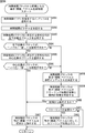
- FIG. 1 It is a figure explaining the example in case a collocated vector is available. It is a figure which shows the example of the syntax of a sequence parameter set. It is a figure which shows the example of the syntax of a slice header. It is a figure which shows the example of the syntax of a prediction unit. It is a flowchart explaining the example of the flow of an encoding process. It is a flowchart explaining the example of the flow of an inter motion prediction process. It is a flowchart explaining the example of the flow of merge mode processing. It is a flowchart explaining the example of the flow of a parallax motion vector prediction process. It is a flowchart explaining the example of the flow of a time parallax correlation prediction process. It is a flowchart following FIG.
- FIG. 22 explaining the example of the flow of a time parallax correlation prediction process. It is a flowchart following FIG. 23 for explaining an example of the flow of temporal disparity correlation prediction processing.
- FIG. 25 is a flowchart following FIG. 24 for explaining an example of the flow of temporal disparity correlation prediction processing. It is a flowchart explaining the example of the flow of a system 1 process. It is a flowchart explaining the example of the flow of a system 3 process.
- 22 is a flowchart for explaining an example of a flow of a method 4-2. It is a block diagram which shows the main structural examples of an image decoding apparatus. It is a block diagram which shows the main structural examples of a motion parallax compensation part.
- FIG. 61 is a flowchart following FIG. 60 for explaining an example of the flow of a prediction vector generation process from different pictures. It is a figure explaining the example of the mode of the reference picture of a background still application. It is a figure explaining the example of the mode of the reference image of a stereo application. It is a figure which compares the example of the type of a reference image, and the characteristic of a vector.
- FIG. 74 is a flowchart subsequent to FIG. 73, illustrating an example of a flow of motion (parallax) vector generation processing that is a candidate from a block on the left side position.
- FIG. 77 is a flowchart subsequent to FIG. 76, illustrating an example of the flow of motion (parallax) vector generation processing that is a candidate from the block at the upper position. It is a flowchart explaining the example of the flow of a motion (parallax) vector of PU, and a reference index production
- FIG. 84 is a flowchart following FIG. 83 for explaining another example of the flow of the motion (parallax) vector generation process that is a candidate from the block on the left side position.
- FIG. 88 is a flowchart following FIG. 87 for explaining another example of the flow of the motion (parallax) vector generation process that is a candidate from the block at the upper position.
- FIG. 89 is a flowchart following FIG. 88 for explaining another example of the flow of the motion (parallax) vector generation process that is a candidate from the block at the upper position. It is a figure explaining the further another example of handling of a time correlation block and a surrounding block. It is a flowchart explaining the further another example of the flow of a motion (parallax) vector generation process which becomes a candidate from the block of the left side position.
- FIG. 92 is a flowchart following FIG. 91, illustrating still another example of the flow of the motion (parallax) vector generation process that is a candidate from the block on the left side position.
- FIG. 26 is a block diagram illustrating a main configuration example of a personal computer. It is a block diagram which shows an example of a schematic structure of a television apparatus. It is a block diagram which shows an example of a schematic structure of a mobile telephone. It is a block diagram which shows an example of a schematic structure of a recording / reproducing apparatus. It is a block diagram which shows an example of a schematic structure of an imaging device.
- First Embodiment> [Motion prediction] In image coding such as AVC (Advanced Video Coding) and HEVC (High Efficiency Video Coding), motion prediction using correlation in the time direction (between frames) is performed.
- AVC Advanced Video Coding
- HEVC High Efficiency Video Coding
- hierarchical blocks such as macroblocks and sub-macroblocks are defined in AVC, but coding units (CU (Coding Unit)) are defined in HEVC. .
- CU Coding Unit
- CU is also called Coding Tree Block (CTB), and is a partial area of a picture unit image that plays the same role as a macroblock in AVC.
- CTB Coding Tree Block
- the latter is fixed to a size of 16 ⁇ 16 pixels, whereas the size of the former is not fixed, and is specified in the image compression information in each sequence.
- the maximum size (LCU (Largest Coding Unit)) and the minimum size ((SCU (Smallest Coding Unit)) are specified. Is done.
- split_flag the value of split_flag is “1”
- the 2N ⁇ 2N size CU is divided into N ⁇ N size CUs that are one level below.
- the CU is divided into prediction units (Prediction Unit (PU)) that are regions (partial regions of images in units of pictures) that are processing units of intra or inter prediction, and regions that are processing units of orthogonal transformation ( This is divided into transform units (Transform Unit (TU)), which is a partial area of an image in units of pictures.
- Prediction Unit PU
- TU Transform Unit
- a macroblock in AVC corresponds to an LCU.
- the size of the LCU of the highest hierarchy is generally set larger than the AVC macroblock, for example, 128 ⁇ 128 pixels.
- area includes all the above-described various areas (for example, macroblock, sub-macroblock, LCU, CU, SCU, PU, TU, etc.) (any of them). .
- units other than those described above may be included, and units that are impossible according to the content of the description are appropriately excluded.
- FIG. 1 shows a configuration example of a prediction unit (PU) that is a prediction processing unit for a CU that is a coding processing unit.
- PU prediction unit
- FIG. 1 shows a configuration example of a prediction unit (PU) that is a prediction processing unit for a CU that is a coding processing unit.
- four types of PUs can be formed for one CU.
- the four large squares shown in FIG. 1 indicate CU, and the rectangle or square inside thereof indicates PU.
- the number indicates the index of each PU and does not indicate the content of the image.
- the CU is composed of one PU (2N ⁇ 2N). That is, in this case, CU and PU are equivalent.
- the CU is divided into two vertically and is composed of two horizontally long PUs (2N ⁇ N).
- the CU is divided into two parts on the left and right, and is composed of two vertically long PUs (N ⁇ 2N).
- the CU is divided into two parts (up to 4 parts in total), and is composed of four square PUs (N ⁇ N). Which of these patterns is applied is determined by the content of the image (cost function value of the prediction result).
- Non-Patent Document 3 proposes a technique (merge mode) called “Motion Partition” Merging as one of motion information encoding methods.
- merge mode two flags, MergeFlag and MergeLeftFlag, are transmitted as merge information that is information related to the merge mode.
- MergeLeftFlag is included in the merge information and transmitted.
- the reference image index includes a peripheral region A adjacent to the left, a peripheral region B adjacent to the upper side, and a peripheral region C adjacent to the upper right with respect to the current region to be processed (Current Block).
- Current Block a peripheral region adjacent to the left
- peripheral region B adjacent to the upper side
- peripheral region C adjacent to the upper right with respect to the current region to be processed
- the second to fourth columns from the left represent the states of the reference image indexes of the peripheral area A to the peripheral area C, respectively.
- the first column from the left is the determined reference image index.
- “X”, “y”, and “z” each indicate an arbitrary natural number, and “ ⁇ 1” indicates that reference is impossible.
- the reference image index of the block is used. If there are two areas that can be referred to from among the peripheral areas A to C, the smallest reference image index is used. Further, when all of the peripheral area A to the peripheral area C cannot be referenced, the reference image index is set to 0.
- the time correlation region located in the temporal vicinity with respect to the current region to be processed is determined as shown in FIG.
- the left shows a partial area of a current picture (CurrPic) (also referred to as a noticed picture) to be processed, and the upper left square among them shows the current area (CurrPU).
- the right side of FIG. 4 shows a partial region of the temporal correlation picture (colPic) located in the temporal vicinity of the current picture.
- a region including a pixel at the same position as the lower right pixel of the current region is defined as a time correlation region (colPU).
- the area including the pixel at the same position as the central pixel of the decoding area is set as a time correlation area (colPU).
- the time correlation picture is determined as shown in FIG. For example, when the current picture is a B picture and collocated_from_l0_flag is 1, the picture with the reference image index 0 in the list L1 is set as a time correlation picture. If the current picture is a P picture or a B picture and collocated_from_l0_flag is 0, the picture with the reference picture index 0 in the list L0 is set as a time correlation picture.
- an interlace flag is set as shown in FIG. 6 depending on the positional relationship between the current picture and the time correlation picture. For example, as shown in the upper part of FIG. 6, when the temporal position of the reference image of the time correlation picture skips the current picture (the current picture exists between the time correlation picture and the reference image), the skip flag is set to 1. Is set.
- the skip flag is set to 0.
- the interlace flag is 1, since the current area is an interpolation of the reference image of the time correlation area and the time correlation area, the reliability of the prediction vector is high.
- the motion vector mvCol in the time correlation region is used.
- the motion vector in the time correlation region is scaled as in the example shown in FIG. That is, based on the temporal distance A between the current region and the reference image in the current region and the temporal distance B between the time correlation region and the reference image in the time correlation region, scaling is performed as in the following equations (1) and (2). Is done.
- the image includes a plurality of views, and parallax prediction using the correlation between the views (parallax direction) is also performed.
- FIG. 8 shows an example of the reference relationship of the three viewpoint images.
- the 3-viewpoint image shown in FIG. 8 includes three views, view 0, view 1, and view 2.
- POC indicates a time index.
- PicNum indicates an index of decoding order.
- View 0 is called a base view and is encoded using temporal prediction that performs prediction using temporal correlation.
- View 1 is called a non-base view and is encoded using temporal prediction and disparity prediction.
- the encoded view 0 and view 2 can be referred to.
- View 2 is called a non-base view and is encoded using temporal prediction and disparity prediction.
- an encoded view 0 can be referred to.
- the conventional prediction vector relates only to the motion vector, and the positional relationship between the same or the most approximate partial images between views generated in the parallax prediction straddling between such viewpoints (views). Coding (prediction) for a disparity vector indicating the above has not been considered.
- This disparity vector is information corresponding to a motion vector for temporal prediction, and is used for temporal prediction for generating a predicted image of the current region using images of different views at the same time. Therefore, the prediction of the disparity vector cannot be performed properly, and there is a possibility that the encoding efficiency is reduced.
- prediction of a disparity vector and a motion vector is performed as follows in a multi-viewpoint image.
- the prediction of the disparity vector in the current region (also referred to as the current disparity vector) is performed as in the example illustrated in FIG.
- the vector of the temporal correlation region (colPicB) included in the temporal correlation picture is a disparity vector that refers to different views at the same time. Adopted as a prediction vector.
- the reference image index 1 (RefPicList [1]) of list 1 is a view correlation picture
- all reference image indexes are candidates for correlated pictures for prediction of the current disparity vector. Further, it is determined whether or not each correlation region vector is a disparity vector, similar to the current region vector.
- the prediction of the motion vector in the current region (also referred to as the current motion vector) is performed as in the example shown in FIG.
- the vector of the temporal correlation area (colPicB) included in the temporal correlation picture is a motion vector that refers to a different time in the same view. Adopted as a prediction vector.
- the vector of the view correlation area (colPicA) included in the view correlation picture refers to a different time of the same view. At this time, it is adopted as a prediction vector.
- all reference image indexes are candidates for correlated pictures in order to predict a current motion vector. Further, it is determined whether or not each correlation region vector is a motion vector, similar to the current region vector.
- the scaling process when the disparity vector is a prediction vector is performed as follows. That is, the prediction vector is scaled based on the inter-view distance between the current region and its reference image and the inter-view distance between the correlation region and its reference image.
- FIG. 11 is a block diagram illustrating a main configuration example of an image encoding device which is an image processing device.
- the image encoding device 100 shown in FIG. 11 encodes image data using a prediction process, such as an encoding method such as AVC or HEVC.
- the image encoding device 100 encodes a multi-viewpoint image including a plurality of views.
- a prediction process such as an encoding method such as AVC or HEVC.
- the image encoding device 100 encodes a multi-viewpoint image including a plurality of views.
- a multi-viewpoint image a case where a 3-viewpoint image including three views is processed will be described.
- the image encoding device 100 can encode a multi-viewpoint image having an arbitrary number of viewpoints (number of views).
- the image encoding device 100 includes an A / D conversion unit 101, a screen rearrangement buffer 102, a calculation unit 103, an orthogonal transformation unit 104, a quantization unit 105, a lossless encoding unit 106, and a storage buffer. 107.
- the image coding apparatus 100 includes an inverse quantization unit 108, an inverse orthogonal transform unit 109, a calculation unit 110, a loop filter 111, a decoded picture buffer 112, a selection unit 113, an intra prediction unit 114, and a motion parallax prediction / compensation unit 115. , A predicted image selection unit 116, and a multi-viewpoint decoded picture buffer 121.
- the A / D conversion unit 101 performs A / D conversion on the input image data, and supplies the converted image data (digital data) to the screen rearrangement buffer 102 for storage.
- the screen rearrangement buffer 102 rearranges the images of the frames in the stored display order in the order of frames for encoding in accordance with GOP (Group Of Picture), and the images in which the order of the frames is rearranged. Along with the view ID and POC of the image, the image is supplied to the calculation unit 103.
- GOP Group Of Picture
- the screen rearrangement buffer 102 supplies the image with the rearranged frame order to the intra prediction unit 114 and the motion parallax prediction / compensation unit 115 together with the view ID and POC of the image.
- the view ID is information for identifying the viewpoint
- the POC is information for identifying the time.
- the calculation unit 103 subtracts the predicted image supplied from the intra prediction unit 114 or the motion parallax prediction / compensation unit 115 via the predicted image selection unit 116 from the image read from the screen rearrangement buffer 102, and the difference Information is output to the orthogonal transform unit 104.
- the calculation unit 103 subtracts the prediction image supplied from the intra prediction unit 114 from the image read from the screen rearrangement buffer 102.
- the arithmetic unit 103 subtracts the predicted image supplied from the motion parallax prediction / compensation unit 115 from the image read from the screen rearrangement buffer 102.
- the orthogonal transform unit 104 performs orthogonal transform such as discrete cosine transform and Karhunen-Loeve transform on the difference information supplied from the computation unit 103. Note that this orthogonal transformation method is arbitrary.
- the orthogonal transform unit 104 supplies the transform coefficient to the quantization unit 105.
- the quantization unit 105 quantizes the transform coefficient supplied from the orthogonal transform unit 104.
- the quantization unit 105 sets a quantization parameter based on information on the code amount target value, and performs the quantization. Note that this quantization method is arbitrary.
- the quantization unit 105 supplies the quantized transform coefficient to the lossless encoding unit 106.
- the lossless encoding unit 106 encodes the transform coefficient quantized by the quantization unit 105 using an arbitrary encoding method. Further, the lossless encoding unit 106 acquires intra prediction information including information indicating an intra prediction mode from the intra prediction unit 114, and obtains inter prediction information including information indicating an inter prediction mode, motion disparity vector information, and the like. Obtained from the motion parallax prediction / compensation unit 115. Further, the lossless encoding unit 106 acquires filter coefficients used in the loop filter 111 and the like.
- the lossless encoding unit 106 encodes these various types of information using an arbitrary encoding method, and makes it a part of the header information of the encoded data (multiplexes).
- the lossless encoding unit 106 supplies the encoded data obtained by encoding to the accumulation buffer 107 for accumulation.
- Examples of the encoding method of the lossless encoding unit 106 include variable length encoding or arithmetic encoding.
- Examples of variable length coding include H.264.
- CAVLC Context-Adaptive Variable Length Coding
- Examples of arithmetic coding include CABAC (Context-Adaptive Binary Arithmetic Coding).
- the accumulation buffer 107 temporarily holds the encoded data supplied from the lossless encoding unit 106.
- the accumulation buffer 107 outputs the stored encoded data as a bit stream at a predetermined timing, for example, to a recording device (recording medium) or a transmission path (not shown) in the subsequent stage. That is, various encoded information is supplied to the decoding side.
- the transform coefficient quantized by the quantization unit 105 is also supplied to the inverse quantization unit 108.
- the inverse quantization unit 108 inversely quantizes the quantized transform coefficient by a method corresponding to the quantization by the quantization unit 105.
- the inverse quantization method may be any method as long as it is a method corresponding to the quantization processing by the quantization unit 105.
- the inverse quantization unit 108 supplies the obtained transform coefficient to the inverse orthogonal transform unit 109.
- the inverse orthogonal transform unit 109 performs inverse orthogonal transform on the transform coefficient supplied from the inverse quantization unit 108 by a method corresponding to the orthogonal transform process by the orthogonal transform unit 104.
- the inverse orthogonal transform method may be any method as long as it corresponds to the orthogonal transform processing by the orthogonal transform unit 104.
- the inversely orthogonally transformed output (difference information restored locally) is supplied to the calculation unit 110.
- the calculation unit 110 converts the inverse orthogonal transformation result supplied from the inverse orthogonal transformation unit 109, that is, locally restored difference information, into the intra prediction unit 114 or the motion parallax prediction / compensation unit via the prediction image selection unit 116.
- the predicted images supplied from 115 are added to obtain a locally reconstructed image (hereinafter referred to as a reconstructed image).
- the reconstructed image is supplied to the loop filter 111 or the decoded picture buffer 112.
- the loop filter 111 includes a deblock filter, an adaptive loop filter, and the like, and appropriately performs a filtering process on the decoded image supplied from the calculation unit 110.
- the loop filter 111 removes block distortion of the decoded image by performing a deblocking filter process on the decoded image.
- the loop filter 111 performs image quality improvement by performing loop filter processing using a Wiener filter on the deblock filter processing result (decoded image from which block distortion has been removed). Do.
- the loop filter 111 may perform arbitrary filter processing on the decoded image. Further, the loop filter 111 can supply information such as filter coefficients used for the filter processing to the lossless encoding unit 106 and encode it as necessary.
- the loop filter 111 supplies a filter processing result (hereinafter referred to as a decoded image) to the decoded picture buffer 112.
- the decoded picture buffer 112 stores the reconstructed image supplied from the calculation unit 110 and the decoded image supplied from the loop filter 111, respectively.
- the decoded picture buffer 112 stores the view ID and POC of the image.
- the decoded picture buffer 112 selects the stored reconstructed image (and the view ID and POC of the image) at a predetermined timing or based on an external request from the intra prediction unit 114 or the like. To the intra prediction unit 114. The decoded picture buffer 112 also stores the decoded image (and the view ID and POC of the image) stored at a predetermined timing or based on a request from the outside such as the motion parallax prediction / compensation unit 115. And supplied to the motion parallax prediction / compensation unit 115 via the selection unit 113.
- the selection unit 113 indicates the supply destination of the image output from the decoded picture buffer 112. For example, in the case of intra prediction, the selection unit 113 reads an unfiltered image (reconstructed image) from the decoded picture buffer 112 and supplies the image as a peripheral pixel to the intra prediction unit 114.
- the selection unit 113 reads out the filtered image (decoded image) from the decoded picture buffer 112, and supplies it as a reference image to the motion parallax prediction / compensation unit 115.
- the intra prediction unit 114 When the intra prediction unit 114 acquires an image (peripheral image) of a peripheral region located around the processing target region from the decoded picture buffer 112, the intra prediction unit 114 basically uses a pixel value of the peripheral image to perform a prediction unit (PU ) As a processing unit, intra prediction (in-screen prediction) for generating a predicted image is performed.
- the intra prediction unit 114 performs this intra prediction in a plurality of modes (intra prediction modes) prepared in advance.
- the intra prediction unit 114 generates predicted images in all candidate intra prediction modes, evaluates the cost function value of each predicted image using the input image supplied from the screen rearrangement buffer 102, and selects the optimum mode. select. When the intra prediction unit 114 selects the optimal intra prediction mode, the intra prediction unit 114 supplies the predicted image generated in the optimal mode to the predicted image selection unit 116.
- the intra prediction unit 114 appropriately supplies intra prediction information including information related to intra prediction, such as an optimal intra prediction mode, to the lossless encoding unit 106 to be encoded.
- the motion parallax prediction / compensation unit 115 basically uses the input image supplied from the screen rearrangement buffer 102 and the reference image supplied from the decoded picture buffer 112 as a processing unit for motion prediction and parallax. Prediction (inter prediction) is performed, compensation processing is performed according to the detected motion parallax vector, and a predicted image (inter predicted image information) is generated.
- the motion parallax prediction / compensation unit 115 performs such inter prediction (inter-screen prediction) in a plurality of modes (inter prediction modes) prepared in advance.
- the motion parallax prediction / compensation unit 115 generates prediction images in all candidate inter prediction modes, evaluates the cost function value of each prediction image, and selects an optimal mode. When selecting the optimal inter prediction mode, the motion parallax prediction / compensation unit 115 supplies the prediction image generated in the optimal mode to the prediction image selection unit 116.
- the motion parallax prediction / compensation unit 115 supplies inter prediction information including information related to inter prediction, such as an optimal inter prediction mode, to the lossless encoding unit 106 and performs encoding.
- the predicted image selection unit 116 selects a supply source of a predicted image to be supplied to the calculation unit 103 or the calculation unit 110.
- the prediction image selection unit 116 selects the intra prediction unit 114 as a supply source of the prediction image, and supplies the prediction image supplied from the intra prediction unit 114 to the calculation unit 103 and the calculation unit 110.
- the prediction image selection unit 116 selects the motion parallax prediction / compensation unit 115 as a supply source of the prediction image, and calculates the prediction image supplied from the motion parallax prediction / compensation unit 115. To the unit 103 and the arithmetic unit 110.
- the decode picture buffer 112 stores only the image of the view to be processed (and the view ID and POC of the image), but the multi-viewpoint decode picture buffer 121 stores the image of each viewpoint (view) (and the image of the image).
- the multi-viewpoint decoded picture buffer 121 acquires the decoded image (and the view ID and POC of the image) supplied to the decoded picture buffer 112, and together with the decoded picture buffer 112, the decoded image (and the view of the image).
- the multi-viewpoint decoded picture buffer 121 acquires the decoded image (and the view ID and POC of the image) supplied to the decoded picture buffer 112, and together with the decoded picture buffer 112, the decoded image (and the view of the image).
- the decoded picture buffer 112 deletes the decoded image, but the multi-viewpoint decoded picture buffer 121 holds it as it is. Then, in accordance with a request from the decoded picture buffer 112 or the like, the stored decoded image (and the view ID and POC of the image) are supplied to the decoded picture buffer 112 as a “decoded image of a view not to be processed”.
- the decoded picture buffer 112 receives the “decoded image of the view not to be processed (and the view ID and POC of the image)” read from the multi-viewpoint decoded picture buffer 121 via the selection unit 113 and the motion parallax prediction / compensation unit. 115.
- FIG. 12 is a block diagram illustrating a main configuration example of the motion parallax prediction / compensation unit in FIG. 11.
- the motion parallax prediction / compensation unit 115 includes a motion parallax vector search unit 131, a predicted image generation unit 132, an encoded information accumulation buffer 133, and a selection unit 134.
- the motion parallax prediction / compensation unit 115 includes a spatial correlation prediction vector generation unit 135, a temporal parallax correlation prediction vector generation unit 136, a selection unit 137, an encoding cost calculation unit 138, and a mode determination unit 139.
- the motion disparity vector search unit 131 acquires a decoded image pixel value from the decoded picture buffer 112 and acquires an original image pixel value from the screen rearrangement buffer 102.
- the motion disparity vector search unit 131 uses them to determine the reference image index of the current region to be processed, performs motion search in the time direction and the disparity direction, and generates a current motion vector and a current disparity vector.
- the motion parallax vector in the current area is also referred to as a current motion parallax vector.
- the motion disparity vector search unit 131 supplies the reference image index and the motion disparity vector to the predicted image generation unit 132 and the encoding cost calculation unit 138.
- the predicted image generation unit 132 acquires a reference image index and a motion disparity vector from the motion disparity vector search unit 131 and also acquires a decoded image pixel value from the decoded picture buffer 112.
- the predicted image generation unit 132 generates a predicted image of the current area using them.
- the predicted image generation unit 132 supplies the predicted image pixel value to the encoding cost calculation unit 138.
- the encoding information accumulation buffer 133 stores mode information indicating the mode selected as the optimum mode by the mode determination unit 139, and the reference image index and motion parallax vector of the mode.
- the encoded information accumulation buffer 133 supplies the stored information to the selection unit 134 at a predetermined timing or according to a request from the outside.
- the selection unit 134 supplies the mode information, the reference image index, and the motion disparity vector supplied from the encoding information accumulation buffer 133 to the spatial correlation prediction vector generation unit 135 or the temporal disparity correlation prediction vector generation unit 136.
- the spatial correlation prediction vector generation unit 135 and the temporal parallax correlation prediction vector generation unit 136 generate a prediction value (prediction vector) of a motion vector (current motion vector) in the current region to be processed.
- the spatial correlation prediction vector generation unit 135 generates a prediction vector (spatial correlation prediction vector) using spatial correlation. More specifically, the spatial correlation prediction vector generation unit 135 receives the current region of the same frame (current frame (also referred to as a frame of interest)) from the encoded information storage buffer 133 via the selection unit 134. Information related to motion information (mode information, reference image index, motion parallax vector, etc.) of a peripheral region (spatial peripheral region) located in the spatial periphery is acquired.
- motion information mode information, reference image index, motion parallax vector, etc.
- the spatial correlation prediction vector generation unit 135 performs a median operation using, for example, motion vectors (space peripheral motion vectors) of a plurality of spatial peripheral regions, and generates a spatial correlation prediction vector.
- the spatial correlation prediction vector generation unit 135 supplies the generated spatial correlation prediction vector to the selection unit 137.
- the temporal disparity correlation prediction vector generation unit 136 generates a prediction vector (temporal disparity correlation prediction vector (temporal correlation prediction vector or disparity correlation prediction vector)) using temporal correlation or disparity correlation. More specifically, the temporal disparity correlation prediction vector generation unit 136, for example, from the encoded information storage buffer 133 via the selection unit 134, the peripheral region (temporal peripheral region) located in the temporal vicinity of the current region. Get information about motion information.
- the temporal peripheral region indicates a region at a position corresponding to the current region of a frame (picture) different from the current frame in the same view as the current region (current view (also referred to as a view of interest)) or a region in the vicinity thereof. .
- the temporal disparity correlation prediction vector generation unit 136 receives information on motion information of a peripheral region (parallax peripheral region) located in the disparity periphery of the current region from the encoded information storage buffer 133 via the selection unit 134.
- the parallax peripheral region refers to a region at a position corresponding to the current region of a frame (picture) at the same time as the current frame in a view different from the view of the current region (current view) or a region in the vicinity thereof.
- the temporal parallax correlation prediction vector generation unit 136 performs, for example, median calculation using motion vectors (temporal peripheral motion vectors) of a plurality of temporal peripheral regions, and generates a temporal correlation prediction vector.
- the temporal parallax correlation prediction vector generation unit 136 performs a median calculation using, for example, motion vectors (parallax peripheral motion vectors) of a plurality of parallax peripheral regions, and generates a parallax correlation prediction vector.
- the temporal parallax correlation prediction vector generation unit 136 supplies the temporal parallax correlation prediction vector generated in this way to the selection unit 137.
- the spatial correlation prediction vector generation unit 135 and the temporal parallax correlation prediction vector generation unit 136 each generate a prediction vector for each inter prediction mode.
- the selection unit 137 supplies the spatial correlation prediction vector supplied from the spatial correlation prediction vector generation unit 135 and the temporal parallax correlation prediction vector supplied from the temporal parallax correlation prediction vector generation unit 136 to the encoding cost calculation unit 138. To do.
- the encoding cost calculation unit 138 uses the predicted image pixel value supplied from the predicted image generation unit 132 and the original image pixel value supplied from the screen rearrangement buffer 102 to calculate a difference value between the predicted image and the original image ( Difference image) is calculated for each inter prediction mode. Also, the encoding cost calculation unit 138 calculates a cost function value (also referred to as an encoding cost value) for each inter prediction mode using the difference image pixel value.
- the coding cost calculation unit 138 is closer to the motion disparity vector of the current region supplied from the motion disparity vector search unit 131 out of the spatial correlation prediction vector and the temporal disparity correlation prediction vector supplied from the selection unit 137. Is selected as the prediction vector of the current region. Also, the coding cost calculation unit 138 generates a differential motion disparity vector that is a difference value between the prediction vector and the motion disparity vector of the current region. The encoding cost calculation unit 138 generates a differential motion disparity vector for each inter prediction mode.
- the coding cost calculation unit 138 performs mode determination on the coding cost value, the predicted image pixel value, the difference motion disparity information including the difference motion disparity vector, and the prediction information including the prediction vector and the reference image index of each inter prediction mode. To the unit 139.
- the mode determination unit 139 selects the inter prediction mode that minimizes the encoding cost value as the optimum mode.
- the mode determination unit 139 supplies the predicted image pixel value of the inter prediction mode selected as the optimal mode to the predicted image selection unit 116.
- the mode determination unit 139 When inter prediction is selected by the prediction image selection unit 116, the mode determination unit 139 includes mode information that is information related to the inter prediction mode selected as the optimal mode, and difference motion disparity information and prediction of the inter prediction mode. Information is supplied to the lossless encoding unit 106 and encoded. These pieces of information are encoded and transmitted to the decoding side.
- the mode determination unit 139 supplies mode information, differential motion disparity information, and prediction information of the inter prediction mode selected as the optimum mode to the encoded information accumulation buffer 133 and stores them. These pieces of information are used as peripheral area information in processing for other areas processed after the current area.
- FIG. 13 is a block diagram illustrating a main configuration example of the temporal parallax correlation predicted vector generation unit 136.
- the temporal parallax correlation prediction vector generation unit 136 includes a current region processing unit (attention region processing unit) 151, a correlation region processing unit 152, an LI prediction processing unit 153, an L0 prediction processing unit 154, and method 1
- a processing unit 155, a method 2 processing unit 156, a method 3 processing unit 157, a method 4 processing unit 158, and a prediction vector generation unit 159 are included.
- the current area processing unit 151 performs processing for acquiring information related to the current area.
- the current region processing unit 151 supplies information on the acquired current region to each of the correlation region processing unit 152 to the L0 prediction processing unit 154.
- the correlation area processing unit 152 performs processing for acquiring information related to the correlation area.
- the correlation area is an area that is referred to in order to use the correlation with the current area.
- the time correlation region is a region that is referred to in order to use the time correlation with the current region, and is a time peripheral region that has a motion vector used to generate a time correlation prediction vector.
- the parallax correlation area is an area that is referred to in order to use the parallax correlation with the current area, and is a parallax peripheral area having a motion vector used for generating the parallax correlation prediction vector.
- the correlation area includes these areas.
- the correlation region processing unit 152 supplies information on the correlation region to the L1 prediction processing unit 153 and the L0 prediction processing unit 154.
- the L1 prediction processing unit 153 performs processing related to prediction in the L1 direction.
- the L1 prediction processing unit 153 acquires necessary information from the screen rearrangement buffer 102 and the decoded picture buffer 112. Further, the L1 prediction processing unit 153 acquires information supplied from the current region processing unit 151 and the correlation region processing unit 152.
- the L1 prediction processing unit 153 performs processing related to prediction in the L1 direction using the information.
- the L1 prediction processing unit selects one of the methods, and provides information to the processing unit corresponding to the selected method among the method 1 processing unit 155 to the method 4 processing unit 158.
- the L0 prediction processing unit 154 performs processing related to prediction in the L0 direction in the same manner as the L1 prediction processing unit 153.
- Method 1 is a case where a frame (reference image) at the same time as the current frame of a view different from the current view assigned to the reference image index 1 in list 1 is a correlation image, and the vector of the correlation region is a disparity vector.
- the disparity vector (reference disparity vector) is used as a prediction vector.
- the method 1 processing unit 155 performs processing for generating a prediction vector according to such a method.
- the method 1 processing unit 155 supplies various parameters obtained as a result of the processing to the prediction vector generation unit 159.
- a frame (reference image) at a time different from the current frame in the same view as the current view, which is assigned to the reference image index 0 in List 1, is used as a correlation image, and a vector of the correlation region is a disparity vector.
- the disparity vector reference disparity vector
- the method 2 processing unit 156 performs processing for generating a prediction vector according to such a method.
- the method 2 processing unit 156 supplies various parameters obtained as a result of the processing to the prediction vector generation unit 159.
- Method 3 a frame (reference image) of the same view as the current view assigned to the reference image index 1 in list 1 is used as a correlation image, and a vector of the correlation region is a motion vector.
- the motion vector reference parallax vector
- the method 3 processing unit 157 performs processing for generating a prediction vector according to such a method.
- the method 3 processing unit 157 supplies various parameters obtained as a result of the processing to the prediction vector generation unit 159.
- Method 4 a frame (reference image) at a time different from the current frame in the same view as the current view, which is assigned to the reference image index 0 in List 1, is used as a correlation image, and a vector of the correlation region is a motion vector.
- the motion vector reference parallax vector
- the method 4 processing unit 158 performs processing for generating a prediction vector according to such a method.
- the method 4 processing unit 158 supplies various parameters obtained as a result of the processing to the prediction vector generation unit 159.
- the prediction vector generation unit 159 uses the information supplied from the method 1 processing unit 155 to the method 4 processing unit 158, the view information of the reference image acquired from the decoded picture buffer 112, the time information, and the like to perform temporal disparity correlation prediction. Generate a vector. At that time, the prediction vector generation unit 159 performs scaling processing using information supplied from the method 1 processing unit 155 to the method 4 processing unit 158. At that time, the prediction vector generation unit 159 performs scaling in the temporal direction for the motion correlation prediction vector, and performs scaling in the parallax direction for the parallax correlation prediction vector. The prediction vector generation unit 159 supplies the generated temporal parallax correlation prediction vector to the encoding cost calculation unit 138 via the selection unit 137.
- the temporal parallax correlation prediction vector generation unit 136 can generate not only a motion correlation prediction vector but also a parallax correlation prediction vector. Therefore, the motion parallax prediction / compensation unit 115 can generate a prediction vector with high prediction accuracy even when the current region vector is a parallax vector. Thereby, the image coding apparatus 100 can suppress a reduction in coding efficiency.
- FIG. 14 shows an example when each method is selected.
- the correlation region is a region in which the positional relationship with the reference image (whether the reference image exists in the time direction or the parallax direction) is the same as in the current region (attention region). Selected as. That is, the positional relationship between the current region and the reference image of the current region is equal to the positional relationship between the correlation region and the reference image of the correlation region. Then, the method is determined by the positional relationship between the current region and the reference image of the current region and the positional relationship between the current region and the correlation region.
- the first to fourth lines from the bottom show examples of the positional relationship of each image
- a to E show examples of view ID or POC values in each line. In other words, what is important here is not the number of values, but whether or not other images match the view ID and POC.
- the POC matches in both the current area and the correlation area, although the reference image and the view ID are different. That is, the vectors of the current area and the correlation area are disparity vectors. Also, the view IDs are different between the current area and the correlation area, and the POCs match. That is, the correlation area is an image of a different view of the frame at the same time as the current area. Therefore, method 1 is selected as shown in the table of FIG. Method 1 is effective in an area where the amount of change in parallax is constant between viewpoints.
- the POC matches. That is, the vectors of the current area and the correlation area are disparity vectors. Also, the view IDs match and the POCs differ between the current area and the correlation area. That is, the correlation area is an image of a frame at a different time in the same view as the current area. Therefore, method 2 is selected as shown in the table of FIG. Method 2 is effective when the change in the amount of motion over time is small.
- both the reference image and the view ID are the same and the POC is different in both the current region and the correlation region. That is, the vectors of the current area and the correlation area are motion vectors. Also, the view IDs are different between the current area and the correlation area, and the POCs match. That is, the correlation area is an image of a different view of the frame at the same time as the current area. Therefore, method 3 is selected as shown in the table of FIG. Method 3 is effective when the change in the amount of parallax between viewpoints is small.
- the reference image and view ID of each of the current region and the correlation region are the same, and the POC is different. That is, the vectors of the current area and the correlation area are motion vectors. Also, the view IDs match and the POCs differ between the current area and the correlation area. That is, the correlation area is an image of a frame at a different time in the same view as the current area. Therefore, method 4 is selected as shown in the table of FIG.
- the vector of the current region (Coding vector) and the correlation region (Co-located block) of the frame of the same view at different times (Co-located block) If the characteristics of the vector (Co-located vector) match, the collocated block is made available. In other words, if the characteristics of the encoded vector and the collocated vector do not match in the dependent view, the collocated block is set as Not Available. Of course, the same may be applied to the base view.
- Whether the characteristics of the encoded vector and the collocated vector coincide with each other can be determined by, for example, comparing each POC of the current region and the collocated block with the POC of each reference image, as shown in FIG. Can be determined.
- the L1 prediction processing unit 153 and the L0 prediction processing unit 154 in FIG. 13 make such a determination.
- the L1 prediction processing unit 153 and the L0 prediction processing unit 154 match the POC (CurrPOC) of the current region and the POC (CurrRefPOC) of the reference image of the current region, and the POC (ColPOC) of the collocated block.
- both the encoded vector and the collocated block are disparity vectors (inter- It is determined that it is a view vector (B in FIG. 16).
- the L1 prediction processing unit 153 and the L0 prediction processing unit 154 for example, based on the determination result, as shown in the lower table of FIG. 15, the availability of the collocated vector (Co-located vector). Set up.
- the collocated vector is available. (A in FIG. 16 or B in FIG. 16).
- the collocated vector is set to Not Available.
- FIG. 17 shows an example of the syntax of the sequence parameter set in this case.
- the total number of views, the ID for distinguishing the views, the number of disparity predictions in the list L0, and the disparity prediction in the list L0 as shown in the 10th row to the 3rd row from the bottom.
- Information such as the ID of the view to be referred to, the number of parallax predictions in the list L1, and the ID of the view to be referred to in the disparity prediction in the list L1 is included in the sequence parameter set.
- These pieces of information are information necessary for a multi-viewpoint image. In other words, the present technology can be applied without adding a new syntax to the sequence parameter set.
- FIG. 18 shows an example of the syntax of the slice header in this case.
- an ID for distinguishing the view is included in the slice header as in the eighth line from the top. This information is necessary for a multi-viewpoint image. In other words, the present technology can be applied without adding a new syntax to the slice header.
- FIG. 19 shows an example of the syntax of the prediction unit in this case.
- the present technology can be applied to a prediction unit without adding a new syntax.
- the number of correlation area candidates will increase compared to the conventional case, so it is necessary to expand the type of syntax or change the processing content in the merge mode and prediction vector ID. is there.
- step S101 the A / D converter 101 performs A / D conversion on the input image.
- step S102 the screen rearrangement buffer 102 stores the A / D converted image, and rearranges the picture from the display order to the encoding order.
- step S103 the intra prediction unit 114 performs an intra prediction process.
- step S104 the motion parallax prediction / compensation unit 115 performs an inter motion prediction process.
- step S105 the predicted image selection unit 116 selects one of a predicted image generated by intra prediction and a predicted image generated by inter prediction.
- step S106 the calculation unit 103 calculates a difference between the image rearranged by the process of step S102 and the predicted image selected by the process of step S105 (generates a difference image).
- the generated difference image has a reduced data amount compared to the original image. Therefore, the data amount can be compressed as compared with the case where the image is encoded as it is.
- step S107 the orthogonal transform unit 104 orthogonally transforms the difference image generated by the process in step S106. Specifically, orthogonal transformation such as discrete cosine transformation and Karhunen-Loeve transformation is performed, and orthogonal transformation coefficients are output.
- step S108 the quantization unit 105 quantizes the orthogonal transform coefficient obtained by the process in step S107.
- the difference image quantized by the process in step S108 is locally decoded as follows. That is, in step S109, the inverse quantization unit 108 inversely quantizes the quantized orthogonal transform coefficient (also referred to as a quantization coefficient) generated by the process in step S108 with characteristics corresponding to the characteristics of the quantization unit 105. To do. In step S ⁇ b> 110, the inverse orthogonal transform unit 109 performs inverse orthogonal transform on the orthogonal transform coefficient obtained by the process of step S ⁇ b> 109 with characteristics corresponding to the characteristics of the orthogonal transform unit 104. Thereby, the difference image is restored.
- the quantized orthogonal transform coefficient also referred to as a quantization coefficient
- step S111 the calculation unit 110 adds the predicted image selected in step S105 to the difference image generated in step S110, and generates a locally decoded image (reconstructed image).
- step S112 the loop filter 111 appropriately performs a loop filter process including a deblocking filter process and an adaptive loop filter process on the reconstructed image obtained by the process of step S111 to generate a decoded image.
- step S113 the decoded picture buffer 112 and the multiview decoded picture buffer 121 store the decoded image generated by the process of step S112 or the reconstructed image generated by the process of step S111.
- step S114 the lossless encoding unit 106 encodes the orthogonal transform coefficient quantized by the process in step S108. That is, lossless encoding such as variable length encoding or arithmetic encoding is performed on the difference image. Note that the lossless encoding unit 106 encodes information about prediction, information about quantization, information about filter processing, and the like, and adds the information to the bitstream.
- step S115 the accumulation buffer 107 accumulates the bit stream obtained by the process in step S114.
- the encoded data stored in the storage buffer 107 is appropriately read and transmitted to the decoding side via a transmission path or a recording medium.
- step S116 the quantization unit 105 performs the quantization operation so that overflow or underflow does not occur based on the code amount (generated code amount) of the encoded data accumulated in the accumulation buffer 107 by the process in step S115. Control the rate.
- step S116 When the process of step S116 is finished, the encoding process is finished.
- step S131 the motion disparity vector search unit 131 performs a motion search for the inter prediction mode to be processed, and generates a motion disparity vector (motion vector or disparity vector) of the current region to be processed.
- step S132 the predicted image generation unit 132 generates a predicted image by performing compensation processing using the motion parallax vector generated in step S131.
- step S133 the encoding cost calculation unit 138 generates a difference image between the predicted image generated in step S132 and the original image (input image).
- step S134 the encoding cost calculation unit 138 performs merge mode processing using the spatial correlation prediction vector generation unit 135, the temporal parallax correlation prediction vector generation unit 136, and the like.
- step S135 the encoding cost calculation unit 138 compares the motion parallax vector of the current region generated in step S131 with the prediction vector of the current region generated by the process of step S134, and the merge mode is set in the current region. Determine whether it applies.
- the encoding cost calculation unit 138 advances the processing to step S136, and uses the spatial correlation prediction vector generation unit 135, the temporal parallax correlation prediction vector generation unit 136, and the like. The parallax motion vector prediction process is performed.
- the encoding cost calculation unit 138 advances the process to step S137.
- step S135 If it is determined in step S135 that the motion parallax vector of the current region matches the prediction vector and the merge mode is applied in the current region, the coding cost calculation unit 138 omits the process of step S136, Proceed to S137.
- step S137 the coding cost calculation unit 138 determines whether or not the above processing has been performed in all inter prediction modes. If it is determined that there is an unprocessed inter prediction mode, the processing proceeds to step S131. The control is performed so that the subsequent processing is repeated for the unprocessed inter prediction mode. That is, each process of step S131 to step S137 is executed for each inter prediction mode.
- step S137 If it is determined in step S137 that the process has been performed for all inter prediction modes, the encoding cost calculation unit 138 advances the process to step S138.
- step S138 the coding cost calculation unit 138 calculates a cost function value for each inter prediction mode.
- step S139 the mode determination unit 139 determines the inter prediction mode having the smallest cost function value (encoding cost value) calculated in step S138 as the optimum mode (optimum inter prediction mode).
- step S140 the predicted image generation unit 132 generates a predicted image in the optimal inter prediction mode. This predicted image is supplied to the predicted image selection unit 116.
- step S141 when the inter prediction is selected in step S105 of FIG. 20, the encoded information accumulation buffer 133 stores the mode information and motion information (motion disparity vector, reference image index, etc.) of the optimal inter prediction mode.
- motion information motion disparity vector, reference image index, etc.
- a zero vector is stored as a motion disparity vector. Note that these pieces of information are also supplied to the lossless encoding unit 106, encoded, and transmitted to the decoding side when inter prediction is selected in step S105 of FIG.
- step S141 the encoded information storage buffer 133 ends the inter motion prediction process and returns the process to FIG.
- step S161 the spatial correlation prediction vector generation unit 135 performs a spatial correlation prediction process for generating a spatial correlation prediction vector using the correlation with the space surrounding area.
- step S162 the temporal parallax correlation predicted vector generation unit 136 performs a temporal correlation prediction process for generating a temporal parallax correlation predicted vector using the correlation with the temporal peripheral area and the parallax peripheral area.
- step S163 the encoding cost calculation unit 138 deletes overlapping vectors between the spatial correlation prediction vector generated in step S161 and the temporal disparity prediction vector generated in step S162.
- step S164 the encoding cost calculation unit 138 determines whether a vector exists. If it is determined that there is at least one spatial correlation prediction vector or temporal disparity correlation prediction vector, the encoding cost calculation unit 138 advances the process to step S165.
- step S165 the encoding cost calculation unit 138 determines whether or not there are a plurality of vectors. If it is determined that there are a plurality of items, the encoding cost calculation unit 138 advances the process to step S166 to acquire a merge index. When it is determined that there are not a plurality, the encoding cost calculation unit 138 omits the process of step S166.
- the encoding cost calculation unit 138 acquires the matching vector as a prediction vector in step S167, and in step S168, Get reference image index.
- step S168 the encoding cost calculation unit 138 ends the merge mode process and returns the process to FIG.
- step S164 If it is determined in step S164 that there is no spatial correlation prediction vector or temporal disparity correlation prediction vector, the coding cost calculation unit 138 advances the process to step S169.
- step S169 the encoding cost calculation unit 138 gives an initial value (for example, a zero vector) to the prediction vector.
- step S170 the encoding cost calculation unit 138 gives an initial value (for example, 0) to the reference image index.
- step S170 the encoding cost calculation unit 138 ends the merge mode process and returns the process to FIG.
- step S191 the spatial correlation prediction vector generation unit 135 performs a spatial correlation prediction process to generate a spatial correlation prediction vector.
- step S192 the temporal parallax correlation prediction vector generation unit 136 performs a temporal parallax correlation prediction process to generate a temporal parallax correlation prediction vector.
- step S193 the coding cost calculation unit 138 deletes a vector that overlaps the spatial correlation prediction vector generated in step S191 and the temporal disparity prediction vector generated in step S192.
- the encoding cost calculation unit 138 selects a vector closest to the motion vector in the current region among the remaining vectors, creates a prediction vector index indicating the vector in step S194, and uses the vector as a prediction vector in step S195. And When the process of step S195 ends, the encoding cost calculation unit 138 ends the parallax motion vector prediction process and returns the process to FIG.
- the current area processing unit 151 acquires the view ID and POC of the current area in step S211 of FIG. In step S212, the current area processing unit 151 determines a reference index of the current area. In step S213, the current area processing unit 151 acquires the view ID and POC of the reference image.
- step S214 the correlation area processing unit 152 selects correlation images in ascending order of the reference image index of the list L1.
- the correlation area processing unit 152 determines whether or not all the reference image indexes have been searched. If it is determined that all the reference image indexes have been referenced, the correlation region processing unit 152 ends the temporal disparity correlation prediction process and performs the processing.
- step S215 If it is determined in step S215 that there is an unprocessed reference image index, the correlation area processing unit 152 advances the process to step S216.
- step S216 the correlation area processing unit 152 determines a correlation area and advances the process to FIG.
- the correlation region processing unit 152 determines whether the correlation region is an intra-predicted region or a region that does not refer to another region. When it is determined that the correlation area is an intra-predicted area or an area that does not refer to other areas, the correlation area processing unit 152 advances the process to FIG.
- step S221 of FIG. 25 If it is determined in step S221 of FIG. 25 that the correlation region is an inter-predicted region and a region that refers to another region, the correlation region processing unit 152 advances the process to step S222. .
- step S222 the L1 prediction processing unit 153 acquires the view ID and POC of the correlation area.
- step S223 the L1 prediction processing unit 153 acquires the view ID and POC of the reference image for the L1 prediction in the correlation region.
- step S224 the L1 prediction processing unit 153 determines whether or not the view IDs of the current area and the correlation area match. If they match, the correlation region is a collocated block. If it is determined that the view IDs of the current region and the correlation region match, the L1 prediction processing unit 153 proceeds to step S225, performs method 4-2 processing, and generates a prediction vector using method 4 or method 2. To. When the process of step S225 ends, the process proceeds to FIG.
- step S224 in FIG. 25 If it is determined in step S224 in FIG. 25 that the view IDs of the current region and the correlation region do not match, the L1 prediction processing unit 153 advances the processing to step S226.
- step S226 the L1 prediction processing unit 153 determines whether or not the POCs of the current region and the correlation region match. When it is determined that the POCs of the current region and the correlation region do not match, the L1 prediction processing unit 153 advances the processing to FIG.
- step S226 of FIG. 25 If it is determined in step S226 of FIG. 25 that the POCs of the current region and the correlation region match, the L1 prediction processing unit 153 advances the processing to step S227.
- step S227 the L1 prediction processing unit 153 determines whether or not the POC of the reference image in the current area matches the reference image in the correlation area. If it is determined that the POC of the reference image in the current region and the reference image in the correlation region match, the L1 prediction processing unit 153 proceeds to step S228, performs method 1 processing, and generates a prediction vector by method 1. To. When the process of step S228 ends, the L1 prediction processing unit 153 advances the process to FIG.
- step S227 in FIG. 25 If it is determined in step S227 in FIG. 25 that the POCs of the reference image in the current area and the reference image in the correlation area do not match, the L1 prediction processing unit 153 advances the process to step S229 and performs the method 3 process.
- the prediction vector is generated by the method 3.
- the L1 prediction processing unit 153 advances the process to FIG.
- the L0 prediction processing unit 154 performs the same processing as the L1 prediction of FIG. 25 for the L0 prediction of the correlation region. That is, the L0 prediction processing unit 154 performs each process from step S231 to step S238 in the same manner as each process from step S222 to step S229 in FIG.
- the reference image of the correlation region is a reference image of L0 prediction.
- the L0 prediction processing unit 154 performs the processing in FIG. Proceed to
- step S241 the predicted vector generation unit 159 determines whether or not there is at least one predicted vector candidate. When it is determined that no prediction vector candidate exists, the prediction vector generation unit 159 returns the process to step S214 in FIG.
- step S241 in FIG. 27 If it is determined in step S241 in FIG. 27 that there is at least one prediction vector candidate, the prediction vector generation unit 159 advances the processing to step S242. In step S242, the prediction vector generation unit 159 determines whether only the L1 jump flag is 1 or the values of the L0 / L1 jump flag are equal and the L1 reference is present.
- the predictive vector generation unit 159 When it is determined that only the L1 interlace flag is 1, or when it is determined that the L0 / L1 interlace flag value is equal and there is an L1 reference, the predictive vector generation unit 159 performs processing. The process proceeds to step S243.
- step S243 the prediction vector generation unit 159 obtains a vector referring to L1.
- step S244 the prediction vector generation unit 159 acquires a reference image index with L1 reference, and the process proceeds to step S247.
- step S242 it is determined that the L1 jump flag is not 1, or the L0 jump flag is also 0, and the L0 / L1 jump flag values are not equal or there is no reference to L1. If it is determined, the prediction vector generation unit 159 proceeds with the process to step S245.
- step S245 the prediction vector generation unit 159 obtains a L0 reference vector.
- step S246 the prediction vector generation unit 159 acquires a reference image index with reference to L0, and the process proceeds to step S247.
- step S247 the prediction vector generation unit 159 sets the acquired L1 reference vector or L0 reference vector as the prediction vector. At that time, the prediction vector generation unit 159 performs vector scaling using the distance from the reference image in the current region or the correlation region, and sets the scaling result as the prediction vector.
- step S247 the prediction vector generation unit 159 returns the process to FIG. 24, ends the temporal disparity correlation prediction process, and returns the process to FIG. 22 or FIG.
- the method 1 processing unit 155 determines in step S261 whether or not the POC of the reference image in the current area matches the reference image in the current area. When it is determined that the POCs of the current region and the reference image in the current region do not match, the method 1 processing unit 155 ends the method 1 processing and returns the processing to FIG. 25 or 26.
- step S261 If it is determined in step S261 that the POCs of the current region and the reference image in the current region match, the method 1 processing unit 155 advances the processing to step S262.
- step S262 the method 1 processing unit 155 determines whether or not the POC of the reference image in the correlation area matches the correlation area. When it is determined that the POCs of the correlation image and the reference image of the correlation region do not match, the method 1 processing unit 155 ends the method 1 processing and returns the processing to FIG. 25 or 26.
- step S262 If it is determined in step S262 that the POCs of the correlation area and the reference image of the correlation area match, the method 1 processing unit 155 advances the process to step S263.
- step S263 the method 1 processing unit 155 calculates the inter-viewpoint distance 1 between the current region and the reference image of the current region.
- step S264 the method 1 processing unit 155 calculates the inter-viewpoint distance 2 between the correlation area and the reference image of the correlation area.
- step S265 the method 1 processing unit 155 determines the interlace flag of the reference image, and returns the process to FIG. 25 or FIG. These parameters (inter-viewpoint distance 1, inter-viewpoint distance 2, and interlace flag) are used for the processing of FIG.
- the method 3 processing unit 157 determines whether or not the view IDs of the current area and the reference image of the current area match in step S271. When it is determined that the view IDs of the current region and the reference image of the current region do not match, the method 3 processing unit 157 ends the method 3 processing and returns the processing to FIG. 25 or 26.
- step S271 If it is determined in step S271 that the view IDs of the current region and the reference image in the current region match, the method 3 processing unit 157 advances the processing to step S272.
- step S272 the method 3 processing unit 157 determines whether or not the view IDs of the correlation area and the reference image of the correlation area match. When it is determined that the view IDs of the correlation image and the reference image in the correlation region do not match, the method 3 processing unit 157 ends the method 3 processing and returns the processing to FIG. 25 or 26.
- step S272 If it is determined in step S272 that the view IDs of the correlation area and the reference image of the correlation area match, the method 3 processing unit 157 advances the process to step S273.
- step S273 the method 3 processing unit 157 calculates the inter-viewpoint distance 1 between the current region and the reference image of the current region.
- step S274 the method 3 processing unit 157 calculates the inter-viewpoint distance 2 between the correlation area and the reference image of the correlation area.
- step S275 the method 3 processing unit 157 determines the interlace flag of the reference image and returns the process to FIG. 25 or FIG. These parameters (inter-viewpoint distance 1, inter-viewpoint distance 2, and interlace flag) are used for the processing of FIG.
- the L1 prediction processing unit 153 or the L0 prediction processing unit 154 determines whether or not the view IDs of the reference images in the current region and the current region match in step S281. If both match, the encoded vector is a motion vector. If it is determined that the view IDs of the reference images in the current area and the current area match, the process proceeds to step S282.
- step S282 the L1 prediction processing unit 153 or the L0 prediction processing unit 154 determines whether or not the correlation ID (collocated block) and the view ID of the reference image in the correlation region match. If they do not match, the collocated vector is a disparity vector. When it is determined that the view IDs of the correlation image and the reference image of the correlation region do not match, the L1 prediction processing unit 153 or the L0 prediction processing unit 154 ends the method 4-2 processing, and the processing is as shown in FIG. 25 or FIG. return.
- the encoded vector is a motion vector and the collocated vector is a disparity vector, the characteristics of the encoded vector do not match the characteristics of the collocated vector. Therefore, the collocated block is set to be not available, and the method 4-2 processing is ended.
- Step S282 when it is determined that the view IDs of the correlation area and the reference image of the correlation area match, the L1 prediction processing unit 153 or the L0 prediction processing unit 154 advances the processing to Step S283. If they match, the collocated vector is a motion vector. That is, in this case, both the encoded vector and the collocated vector are motion vectors, and the characteristics of both vectors match. Therefore, in this case, the collocated vector is set to be available.
- step S283 the method 4 processing unit 158 calculates the inter-viewpoint distance 1 between the current region and the reference image of the current region.
- step S284 the method 4 processing unit 158 calculates the inter-viewpoint distance 2 between the correlation area and the reference image of the correlation area.
- step S285 the method 4 processing unit 158 determines the interlace flag of the reference image and returns the process to FIG. 25 or FIG. These parameters (inter-viewpoint distance 1, inter-viewpoint distance 2, and interlace flag) are used for the processing of FIG.
- step S281 If it is determined in step S281 that the view IDs of the current region and the reference image of the current region do not match, the L1 prediction processing unit 153 or the L0 prediction processing unit 154 advances the processing to step S286.
- step S286 the prediction processing unit 153 or the L0 prediction processing unit 154 determines whether or not the POC of the reference image in the current area matches the reference image in the current area. If it is determined that the POCs of the current region and the reference image of the current region do not match, the prediction processing unit 153 or the L0 prediction processing unit 154 ends the method 4-2 processing, and returns the processing to FIG. 25 or FIG.
- step S286 If it is determined in step S286 that the POCs of the current region and the reference image in the current region match, the prediction processing unit 153 or the L0 prediction processing unit 154 advances the processing to step S287. If they match, the encoded vector is a disparity vector.
- step S287 the prediction processing unit 153 or the L0 prediction processing unit 154 determines whether or not the POC of the reference image in the correlation area matches the correlation area. If they do not match, the collocated vector is a motion vector. When it is determined that the POCs of the correlation image and the reference image of the correlation region do not match, the prediction processing unit 153 or the L0 prediction processing unit 154 ends the method 4-2 and returns the processing to FIG. 25 or FIG.
- the encoded vector is a disparity vector and the collocated vector is a motion vector, the characteristics of the encoded vector and the characteristics of the collocated vector do not match. Therefore, the collocated block is set to be not available, and the method 4-2 processing is ended.
- Step S287 when it is determined that the POC of the correlation area and the reference image of the correlation area match, the L1 prediction processing unit 153 or the L0 prediction processing unit 154 returns the process to Step S283. If they match, the collocated vector is a disparity vector. That is, in this case, both the encoded vector and the collocated vector are disparity vectors, and the characteristics of both vectors match. Therefore, in this case, the collocated vector is set to be available.
- the method 2 processing unit 156 performs the processing from step S283 to step S285 similarly to the case where the method 4 processing unit 158 executes.
- the method 2 processing unit 156 ends the method 4-2 processing, and returns the processing to FIG. 25 or FIG.
- the temporal disparity correlation prediction vector generation unit 136 can generate not only a motion correlation prediction vector but also a disparity correlation prediction vector. Therefore, the motion parallax prediction / compensation unit 115 can generate a prediction vector with high prediction accuracy even when the current region vector is a parallax vector. Thereby, the image coding apparatus 100 can suppress a reduction in coding efficiency.
- FIG. 31 is a block diagram illustrating a main configuration example of an image decoding device which is an image processing device.
- An image decoding apparatus 300 shown in FIG. 31 is an apparatus corresponding to the image encoding apparatus 100 of FIG. That is, the image decoding apparatus 300 decodes encoded data (bitstream) generated by encoding the multi-viewpoint image by the image encoding apparatus 100 using a decoding method corresponding to the encoding method of the image encoding apparatus 100, A multi-view decoded image is obtained.
- the image decoding apparatus 300 includes an accumulation buffer 301, a lossless decoding unit 302, an inverse quantization unit 303, an inverse orthogonal transform unit 304, a calculation unit 305, a loop filter 306, a screen rearrangement buffer 307, and A D / A converter 308 is included.
- the image decoding device 300 includes a decoded picture buffer 309, a selection unit 310, an intra prediction unit 311, a motion parallax compensation unit 312, and a selection unit 313.
- the image decoding device 300 has a multi-viewpoint decoded picture buffer 321.
- the accumulation buffer 301 accumulates the transmitted encoded data, and supplies the encoded data to the lossless decoding unit 302 at a predetermined timing.
- the lossless decoding unit 302 decodes the information supplied from the accumulation buffer 301 and encoded by the lossless encoding unit 106 in FIG. 11 using a method corresponding to the encoding method of the lossless encoding unit 106.
- the lossless decoding unit 302 supplies the quantized coefficient data of the difference image obtained by decoding to the inverse quantization unit 303.
- the lossless decoding unit 302 refers to information on the optimal prediction mode obtained by decoding the encoded data, and determines whether the intra prediction mode or the inter prediction mode is selected as the optimal prediction mode. .
- the lossless decoding unit 302 supplies information on the optimal prediction mode to the intra prediction unit 311 or the motion parallax compensation unit 312 based on the determination result. That is, for example, when the intra prediction mode is selected as the optimal prediction mode in the image encoding device 100, intra prediction information that is information related to the optimal prediction mode is supplied to the intra prediction unit 311. For example, when the inter prediction mode is selected as the optimal prediction mode in the image encoding device 100, inter prediction information that is information related to the optimal prediction mode is supplied to the motion parallax compensation unit 312.
- the inverse quantization unit 303 inversely quantizes the quantized coefficient data obtained by decoding by the lossless decoding unit 302 using a method corresponding to the quantization method of the quantization unit 105 in FIG.
- Data is supplied to the inverse orthogonal transform unit 304.
- the inverse orthogonal transform unit 304 performs inverse orthogonal transform on the coefficient data supplied from the inverse quantization unit 303 by a method corresponding to the orthogonal transform method of the orthogonal transform unit 104 in FIG.
- the inverse orthogonal transform unit 304 obtains a difference image corresponding to the difference image before being orthogonally transformed in the image encoding device 100 by the inverse orthogonal transform process.
- the difference image obtained by the inverse orthogonal transform is supplied to the calculation unit 305.
- a predicted image is supplied to the calculation unit 305 from the intra prediction unit 311 or the motion parallax compensation unit 312 via the selection unit 313.
- the calculation unit 305 adds the difference image and the prediction image, and obtains a reconstructed image corresponding to the image before the prediction image is subtracted by the calculation unit 103 of the image encoding device 100.
- the calculation unit 305 supplies the reconstructed image to the loop filter 306.
- the loop filter 306 appropriately performs loop filter processing including deblock filter processing and adaptive loop filter processing on the supplied reconstructed image to generate a decoded image.
- the loop filter 306 removes block distortion by performing deblocking filter processing on the reconstructed image.
- the loop filter 306 improves the image quality by performing loop filter processing using the Wiener filter on the deblock filter processing result (reconstructed image from which block distortion has been removed). I do.
- the type of filter processing performed by the loop filter 306 is arbitrary, and filter processing other than that described above may be performed. Further, the loop filter 306 may perform the filtering process using the filter coefficient supplied from the image encoding device 100 of FIG.
- the loop filter 306 supplies the decoded image as the filter processing result to the screen rearrangement buffer 307 and the decoded picture buffer 309. Note that the filtering process by the loop filter 306 can be omitted. That is, the output of the arithmetic unit 305 can be stored in the decoded picture buffer 309 without being subjected to filter processing.
- the intra prediction unit 311 uses pixel values of pixels included in this image as pixel values of peripheral pixels.
- the screen rearrangement buffer 307 rearranges the supplied decoded images. That is, the order of frames rearranged for the encoding order by the screen rearrangement buffer 102 in FIG. 11 is rearranged in the original display order.
- the D / A conversion unit 308 D / A converts the decoded image supplied from the screen rearrangement buffer 307, outputs it to a display (not shown), and displays it.
- the decoded picture buffer 309 stores the supplied reconstructed image (and the view ID and POC of the image) and the decoded image (and the view ID and POC of the image). In addition, the decoded picture buffer 309 stores the reconstructed image (and the view ID and the image ID) stored at a predetermined timing or based on an external request such as the intra prediction unit 311 or the motion parallax compensation unit 312. POC) and the decoded image (and the view ID and POC of the image) are supplied to the intra prediction unit 311 and the motion parallax compensation unit 312 via the selection unit 310.
- the intra prediction unit 311 performs basically the same processing as the intra prediction unit 114 in FIG. However, the intra prediction unit 311 performs intra prediction only on a region where a prediction image is generated by intra prediction at the time of encoding.
- the motion parallax compensation unit 312 performs motion parallax compensation based on the inter prediction information supplied from the lossless decoding unit 302, and generates a predicted image. Note that the motion parallax compensation unit 312 performs motion parallax compensation only on the region on which inter prediction has been performed based on the inter prediction information supplied from the lossless decoding unit 302.
- the motion parallax compensation unit 312 supplies the generated predicted image to the calculation unit 305 via the selection unit 313 for each region of the prediction processing unit.
- the selection unit 313 supplies the prediction image supplied from the intra prediction unit 311 or the prediction image supplied from the motion parallax compensation unit 312 to the calculation unit 305.
- the decode picture buffer 309 stores only the image of the view to be processed (and the view ID and POC of the image), while the multi-view decode picture buffer 321 stores the image of each viewpoint (view) (and the image of the image).
- the multi-viewpoint decoded picture buffer 321 acquires the decoded image (and the view ID and POC of the image) supplied to the decoded picture buffer 309, and together with the decoded picture buffer 309, the decoded image (and the view of the image).
- the multi-viewpoint decoded picture buffer 321 acquires the decoded image (and the view ID and POC of the image) supplied to the decoded picture buffer 309, and together with the decoded picture buffer 309, the decoded image (and the view of the image).
- the decoded picture buffer 309 deletes the decoded image, but the multi-viewpoint decoded picture buffer 321 holds it as it is. Then, in accordance with a request from the decoded picture buffer 309 or the like, the stored decoded image (and the view ID and POC of the image) are supplied to the decoded picture buffer 309 as a “decoded image of a view not to be processed”.
- the decoded picture buffer 309 transmits the “decoded image of the view not to be processed (and the view ID and POC of the image) read out from the multi-viewpoint decoded picture buffer 321 to the motion parallax compensation unit 312 via the selection unit 310. Supply.
- FIG. 32 is a block diagram illustrating a main configuration example of the motion parallax compensation unit 312.
- the motion disparity compensation unit 312 includes an encoded information accumulation buffer 331, a spatial correlation prediction vector generation unit 332, a temporal parallax correlation prediction vector generation unit 333, a selection unit 334, a calculation unit 335, and a prediction image.
- a generation unit 336 is included.
- the encoded information accumulation buffer 331 acquires mode information, differential motion disparity information, and prediction information obtained in the lossless decoding unit 302.
- the encoded information accumulation buffer 331 stores the decoded motion disparity vector used in the predicted image generation unit 336. This motion disparity vector is used as a motion disparity vector of the peripheral region in processing for other regions.
- the encoded information accumulation buffer 331 uses the prediction information specified in the prediction information of the spatial correlation prediction vector generation unit 332 or the temporal disparity correlation prediction vector generation unit 333 to convert the mode information and the motion parallax vector of the decoded peripheral region. Is supplied to the one corresponding to the type (spatial correlation prediction vector or temporal parallax correlation prediction vector).
- the encoded information accumulation buffer 331 supplies the difference motion disparity vector included in the difference motion disparity information to the calculation unit 335. Further, the encoded information accumulation buffer 331 supplies the reference image index included in the prediction information to the predicted image generation unit 336.
- the spatial correlation prediction vector generation unit 332 generates a spatial correlation prediction vector based on the information supplied from the encoded information accumulation buffer 331. This generation method is the same as that of the spatial correlation prediction vector generation unit 135. However, in the case of the spatial correlation prediction vector generation unit 332, since the optimal inter prediction mode is determined in advance, a spatial correlation prediction vector need only be generated for that mode.
- the spatial correlation prediction vector generation unit 332 supplies the generated spatial correlation prediction vector to the calculation unit 335 via the selection unit 334.
- the temporal disparity correlation prediction vector generation unit 333 is supplied from the information supplied from the encoded information accumulation buffer 331, information such as the view ID and POC of the current region supplied from the lossless decoding unit 302, and the decoded picture buffer 309. A temporal disparity correlation prediction vector is generated based on information such as the view ID and POC of the reference image. This generation method is the same as that in the case of the temporal parallax correlation prediction vector generation unit 136. However, in the case of the temporal disparity correlation prediction vector generation unit 333, since the optimal inter prediction mode is determined in advance, it is only necessary to generate a temporal disparity correlation prediction vector for that mode. The temporal parallax correlation prediction vector generation unit 333 supplies the generated temporal parallax correlation prediction vector to the calculation unit 335 via the selection unit 334.
- the selection unit 334 supplies the calculation unit 335 with it. Further, when the temporal parallax correlation prediction vector generation unit 333 is supplied with the temporal parallax correlation prediction vector generation unit 333, the selection unit 334 supplies it to the calculation unit 335.
- the calculation unit 335 adds the differential motion disparity vector supplied from the encoded information accumulation buffer 331 to the spatial correlation prediction vector or temporal disparity correlation prediction vector supplied from the selection unit 334, and re-generates the motion disparity vector in the current region. To construct.
- the calculation unit 335 supplies the reconstructed motion disparity vector of the current region to the predicted image generation unit 336.
- the predicted image generation unit 336 is supplied from the arithmetic unit 335, the reconstructed motion parallax vector of the current region, the reference image index supplied from the encoded information accumulation buffer 331, and the decoded picture buffer 309.
- a predicted image is generated using peripheral image pixel values that are images of the peripheral region.
- the predicted image generation unit 336 supplies the generated predicted image pixel value to the selection unit 313.
- the temporal parallax correlation prediction vector generation unit 333 can generate not only the motion correlation prediction vector but also the parallax correlation prediction vector as in the case of the temporal parallax correlation prediction vector generation unit 136. Therefore, the motion parallax compensation unit 312 can reconstruct a parallax correlation prediction vector even when the vector of the current region is a parallax vector. That is, since the image decoding apparatus 300 can correctly decode the encoded data generated by the image encoding apparatus 100, the encoding efficiency can be improved.
- the accumulation buffer 301 accumulates the transmitted bit stream in step S301.
- the lossless decoding unit 302 decodes the bitstream (encoded difference image information) supplied from the accumulation buffer 301.
- various types of information other than the difference image information included in the bit stream such as intra prediction information and inter prediction information are also decoded.
- step S303 the inverse quantization unit 303 inversely quantizes the quantized orthogonal transform coefficient obtained by the process in step S302.
- step S304 the inverse orthogonal transform unit 304 performs inverse orthogonal transform on the orthogonal transform coefficient inversely quantized in step S303.
- step S305 the intra prediction unit 311 or the motion parallax compensation unit 312 performs a prediction process using the supplied information.
- step S306 the calculation unit 305 adds the predicted image generated in step S305 to the difference image information obtained by the inverse orthogonal transform in step S304. Thereby, a reconstructed image is generated.
- step S307 the loop filter 306 appropriately performs a loop filter process including a deblock filter process and an adaptive loop filter process on the reconstructed image obtained in step S306.
- step S308 the screen rearrangement buffer 307 rearranges the decoded images generated by the filtering process in step S307. That is, the order of frames rearranged for encoding by the screen rearrangement buffer 102 of the image encoding device 100 is rearranged to the original display order.
- step S309 the D / A converter 308 D / A converts the decoded image in which the frame order is rearranged.
- the decoded image is output and displayed on a display (not shown).
- step S310 the decoded picture buffer 309 stores the decoded image obtained by the filtering process in step S307. This decoded image is used as a reference image in the inter prediction process.
- step S310 ends, the decryption process ends.
- the lossless decoding unit 302 determines in step S331 whether intra prediction has been performed when the current region to be processed is encoded. If it is determined that intra prediction has been performed, the lossless decoding unit 302 advances the process to step S332.
- the intra prediction unit 311 acquires the intra prediction mode information from the lossless decoding unit 302 in step S332, and generates a predicted image by intra prediction in step S333.
- the intra prediction unit 311 ends the prediction process, and returns the process to FIG.
- step S331 If it is determined in step S331 that the current region is an inter-predicted region, the lossless decoding unit 302 advances the process to step S334.
- step S334 the motion parallax compensation unit 312 performs a motion parallax compensation process. When the motion parallax compensation processing ends, the motion parallax compensation unit 312 ends the prediction processing and returns the processing to FIG.
- step S351 the encoded information accumulation buffer 331 stores the mode information, the motion parallax information, the prediction information, and the like decoded in step S351.
- step S352 the spatial correlation prediction vector generation unit 332, the temporal parallax correlation prediction vector generation unit 333, the selection unit 334, and the calculation unit 335 perform motion parallax vector generation processing to reconstruct the motion parallax vector of the current region.
- step S353 the predicted image generation unit 336 generates a predicted image using the motion disparity vector.
- the predicted image generation unit 336 ends the motion parallax compensation process and returns the process to FIG.
- the encoded information accumulation buffer 331 determines whether or not it is a skip mode from the prediction information in step S371. If it is determined that the mode is the skip mode, the encoded information storage buffer 331 advances the process to step S372. In step S372, the spatial correlation prediction vector generation unit 332 to the calculation unit 335 perform merge mode processing and reconstruct a motion disparity vector in the merge mode. In the merge mode process, the same process as that described with reference to the flowchart of FIG. 22 is performed. When the merge mode process ends, the calculation unit 335 ends the motion disparity vector generation process and returns the process to FIG.
- step S371 in FIG. 36 If it is determined in step S371 in FIG. 36 that the skip mode is not set, the encoded information storage buffer 331 advances the process to step S373. In step S373, the encoded information accumulation buffer 331 determines whether or not the merge mode is set based on the prediction information. If it is determined that the mode is the merge mode, the encoded information storage buffer 331 returns the process to step S372 to execute the merge mode process.
- step S373 If it is determined in step S373 that the mode is not the merge mode, the encoded information storage buffer 331 advances the process to step S374.
- step S374 the encoded information storage buffer 331 acquires the index of the reference image.
- step S375 the encoded information accumulation buffer 331 acquires a differential motion disparity vector.
- step S376 the spatial correlation prediction vector generation unit 332 or the temporal parallax correlation prediction vector generation unit 333 performs a parallax motion vector prediction process.
- This parallax motion vector prediction process is performed in the same manner as described with reference to the flowchart of FIG. However, in this case, since the prediction method is determined, one of the spatial correlation prediction process and the temporal parallax correlation prediction process (one specified by the prediction information) is performed.
- step S377 the calculation unit 335 adds the prediction vector reconstructed in step S376 and the differential motion disparity vector to reconstruct the motion disparity vector.
- step S377 the arithmetic unit 335 ends the motion parallax vector generation process and returns the process to FIG.
- the temporal disparity correlation predicted vector generation unit 333 By executing each process as described above, the temporal disparity correlation predicted vector generation unit 333 generates not only a motion correlation predicted vector but also a disparity correlation predicted vector as in the case of the temporal disparity correlation predicted vector generation unit 136. can do. Therefore, the motion parallax compensation unit 312 can reconstruct a parallax correlation prediction vector even when the vector of the current region is a parallax vector. That is, since the image decoding apparatus 300 can correctly decode the encoded data generated by the image encoding apparatus 100, the encoding efficiency can be improved.
- the block at the shifted position is selected. That is, a prediction vector is generated using a vector of a region that is at the same position as the current region in a state where the position of the image at the same time as the current region is shifted.
- This shift amount is calculated by a predetermined procedure from the disparity vectors of the surrounding blocks. By making this procedure common to the encoding side device and the decoding side device, the same prediction can be performed on the encoding side and the decoding side.
- peripheral blocks for calculating the shift amount may be explicitly specified, and the information may be transmitted from the encoding side to the decoding side. In addition, information regarding the shift amount calculation method may also be transmitted from the encoding side to the decoding side.
- both the image encoding device and the image decoding device can generate a prediction vector from a block aligned between views. Therefore, the prediction accuracy of the predicted image can be improved, and the encoding efficiency can be improved.
- FIG. 37 is a block diagram illustrating another configuration example of the image encoding device to which the present technology is applied.
- An image encoding device 400 shown in FIG. 37 is basically the same device as the image encoding device 100 described above. However, the image coding apparatus 400 generates a prediction vector from blocks aligned between views.
- the image encoding device 400 includes a motion prediction / compensation unit 415 and a Base IV encoder 421.
- the motion prediction / compensation unit 412 uses the decoded image acquired from the decoded picture buffer 112 and the base view motion information acquired from the Base view encoder 421 to generate a prediction vector that refers to a block in the view direction.
- the Base View encoder 421 performs base view encoding.
- the Base View encoder 421 supplies the decoded picture of the base view to the decoded picture buffer 112 and stores it.
- the decoded picture buffer 112 also stores a non-base view decoded image supplied from the loop filter 111.
- the Base View encoder 421 supplies base view motion information to the motion prediction / compensation unit 412.
- FIG. 38 is a block diagram illustrating a main configuration example of the motion prediction / compensation unit 412 of FIG.
- the motion prediction / compensation unit 412 includes an inter mode generation unit 431, a reference index determination unit 432, a vector prediction unit 433, a vector prediction unit 434, and a mode determination unit 435. Information shown in FIG. 38 is exchanged between the processing units.
- the vector prediction unit 433 In the inter prediction mode, the vector prediction unit 433 generates a prediction vector and generates a predicted image.
- the vector prediction unit 434 generates a prediction vector and generates a predicted image in the skip mode, the merge mode, or the like.
- the prediction vector and the prediction image generated in these are supplied to the mode determination unit 435.
- the mode determination unit 435 performs mode determination based on these pieces of information, and supplies the mode information indicating the selected mode and the prediction vector of the mode to the lossless encoding unit 106. Further, the predicted image in the selected mode is supplied to the predicted image selection unit 116.
- FIG. 39 is a block diagram illustrating a main configuration example of the vector prediction unit 433.
- the vector prediction unit 433 includes a motion / disparity vector search unit 451, a predicted image generation unit 452, a vector cost calculation unit 453, a vector determination unit 454, a vector information accumulation buffer 455, and prediction from surrounding blocks.
- a vector generation unit 456, a prediction vector generation unit 457 from different pictures, and a selection unit 458 are included. Information shown in FIG. 39 is exchanged between the processing units.
- the prediction vector generation unit 457 from different pictures generates prediction vectors that refer to different pictures. That is, the prediction vector generation unit 457 from different pictures refers to different pictures in each of the temporal direction and the view direction to generate a prediction vector.
- the prediction vector generation unit 457 from the different picture acquires the motion information of the base view from the Base View encoder 421, and uses the motion information to calculate the prediction vector. Generate.
- the prediction vector generated by the prediction vector generation unit 457 from different pictures is supplied to the vector cost calculation unit 453 via the selection unit 458, and a cost function value used for mode determination is calculated.
- FIG. 40 is a block diagram illustrating a main configuration example of the prediction vector generation unit 457 from different pictures.
- the prediction vector generation unit 457 from different pictures includes a disparity vector determination unit 471, an inter-view reference vector generation unit 472, and an intra-view reference vector generation unit 473.
- the disparity vector determination unit 471 calculates the shift amount of the reference image from the disparity vectors of the surrounding blocks.
- the method for calculating the shift amount is arbitrary. For example, any one of the disparity vectors of the peripheral blocks may be selected and used as the shift amount. In addition, for example, an average value or a median value of disparity vectors of peripheral blocks may be used as the shift amount.
- the disparity vector determination unit 471 supplies the shift amount thus determined to the inter-view reference vector generation unit 472 as a disparity vector.
- the inter-view reference vector generation unit 472 generates a prediction vector that refers to different pictures in the view direction.
- the inter-view reference vector generation unit 472 includes a disparity vector (shift amount) selected by the disparity vector determination unit 471 and a base view motion vector supplied from the Base View encoder 421 (including a disparity vector in the case of a non-base view).
- a disparity vector shift amount selected by the disparity vector determination unit 471
- a base view motion vector supplied from the Base View encoder 421 including a disparity vector in the case of a non-base view.
- a prediction vector considering the disparity vector is generated.
- the inter-view reference vector generation unit 472 aligns (shifts) the image of the referenced view using the shift amount calculated by the disparity vector determination unit 471. Then, the inter-view reference vector generation unit 472 generates a prediction vector from the block subjected to the alignment.
- the inter-view reference vector generation unit 472 supplies the generated prediction vector to the vector cost calculation unit 453 via the selection unit 458 (not shown in FIG. 40).
- the intra-view reference vector generation unit 473 generates a prediction vector that refers to a different picture in the temporal direction.
- the inter-view reference vector generation unit 472 can create an appropriate prediction vector with high prediction accuracy. Thereby, the image coding apparatus 400 can improve coding efficiency.
- the inter mode generation unit 431 selects one of the inter prediction mode, the skip mode, the merge mode, and the like in step S401, and specifies the mode. Generate a mode.
- step S402 the inter mode generation unit 431 determines whether or not the generated inter mode is the inter prediction mode.
- step S403 the inter mode generation unit 431 determines a reference image, and in step S404, the vector prediction unit 433 executes vector prediction processing.
- the vector prediction unit 434 performs vector prediction processing in step S404.
- step S405 the mode determination unit 435 determines the mode based on the prediction vector generated in step S404. This mode is used for the process of step S401.
- step S405 the lossless encoding unit 106 encodes the mode information determined in step S405.
- the motion / disparity vector search unit 451 searches for a vector in step S421.
- step S422 the predicted image generation unit 452 generates a predicted image.
- step S423 the vector cost calculation unit 453 generates a residual image.
- step S424 the prediction vector generation unit 456 from neighboring blocks and the prediction vector generation unit 457 from different pictures generate prediction vectors from the encoded vectors.
- step S425 the vector cost calculation unit 453 calculates the residual of the vector.
- step S426 the vector determination unit 454 determines the prediction vector with the minimum cost. This processing result is reflected in the processing in step S424.
- step S427 the vector information accumulation buffer 455 accumulates the vector information and returns the process to FIG.
- the selection unit 458 determines which block is to be referred to in step S441.
- the prediction vector generation unit 456 from the peripheral block sets the encoded vector of the peripheral block as the prediction vector in step S442, and returns the processing to FIG.
- step S441 If it is determined in step S441 to refer to a block of a different picture, the selection unit 458 advances the process to step S443 to determine which view picture to reference.
- the prediction vector generation unit 457 from the different picture, in step S444, from the encoded collocated block (Co-located Block) expanded in the view direction. A prediction vector is generated, and the processing returns to FIG.
- step S443 If it is determined in step S443 to refer to a picture of the same view, the prediction vector generation unit 457 from a different picture in time direction from the encoded collocated block (Co-located Block) in step S445. A prediction vector is generated, and the processing returns to FIG.
- the disparity vector determination unit 471 determines the shift amount from the disparity vectors of the surrounding blocks in step S461.
- step S462 the inter-view reference vector generation unit 472 selects the collocated block at the shifted position.
- step S463 the inter-view reference vector generation unit 472 generates a prediction vector from the collocated block, and returns the process to FIG.
- step S481 the disparity vector determination unit 471 determines whether or not there are a plurality of blocks having non-zero Y direction vector values in the disparity vectors of the surrounding blocks.
- the peripheral block is a block located in the vicinity (including “adjacent”) of the current block (current block) to be processed. For example, as shown in FIG. 46, a block adjacent to the left of the current block (Curr) (Left), a block adjacent to the current block (Above), and a block adjacent to the upper right of the current block (Above Right) ) Is a peripheral block.
- a block adjacent to the current block (Above) a block adjacent to the upper right of the current block (Above Right)
- other blocks may be included in the peripheral blocks, or some or all of these blocks may not be used as the peripheral blocks.
- the position of the peripheral block may be common to all blocks, but may be different depending on the block. For example, when a block adjacent to the screen edge or slice boundary is set as the current block, a part of the peripheral blocks may be disabled.
- step S481 If it is determined in step S481 that there are not a plurality of blocks having non-zero Y-direction vector values, the disparity vector determination unit 471 advances the processing to step S482, sets the target disparity vector in the X direction as a shift amount, and performs processing. Return to FIG.
- step S481 If it is determined in step S481 that there are a plurality of blocks having non-zero Y-direction vector values, the disparity vector determination unit 471 proceeds to step S483 and shifts the average value of the target X-direction disparity vectors. The process returns to FIG.
- the motion prediction / compensation unit 415 can create an appropriate prediction vector with high prediction accuracy. Thereby, the image coding apparatus 400 can improve coding efficiency.
- FIG. 47 is a block diagram illustrating another configuration example of the image decoding device to which the present technology is applied.
- An image decoding apparatus 500 shown in FIG. 47 is basically the same apparatus as the image decoding apparatus 300 described above. However, as in the case of the image encoding device 400, the image decoding device 500 generates a prediction vector from blocks aligned between views.
- the image decoding apparatus 500 includes a motion compensation unit 512 and a Base IV view decoder 521.
- the motion compensation unit 512 uses the decoded image acquired from the decoded picture buffer 309 and the motion information of the base view acquired from the Base30view decoder 521 to generate a prediction vector that refers to a block in the view direction.
- the Base View decoder 521 performs base view encoding.
- the Base View decoder 521 supplies the decoded image of the base view to the decoded picture buffer 309 and stores it.
- the decoded picture buffer 309 also stores a non-base view decoded image supplied from the loop filter 306.
- the Base View decoder 521 supplies base view motion information to the motion compensation unit 512.
- FIG. 48 is a block diagram illustrating a main configuration example of the motion compensation unit 512 of FIG.
- the motion compensation unit 512 includes a mode determination unit 531, a reference index determination unit 532, a vector decoding unit 533, and a vector decoding unit 534. Information shown in FIG. 48 is exchanged between the processing units.
- the vector decoding unit 533 decodes the residual vector transmitted from the image encoding device 400 and generates a prediction vector. Moreover, the vector decoding part 533 produces
- the vector decoding unit 534 decodes the residual vector transmitted from the image encoding device 400 and generates a prediction vector. Further, the vector decoding unit 534 generates a prediction image using the prediction vector. The predicted image is supplied to the predicted image selection unit 313.
- FIG. 49 is a block diagram illustrating an exemplary main configuration of the vector decoding unit 533.
- the vector decoding unit 533 includes a selection unit 551, a prediction vector generation unit 552 from neighboring blocks, a prediction vector generation unit 553 from different pictures, a selection unit 554, a calculation unit 555, and a prediction image generation unit. 556 and a vector information storage buffer 557. Information shown in FIG. 49 is exchanged between the processing units.
- the selection unit 551 selects the vector index supplied from the lossless decoding unit 302 based on the prediction mode generation unit 552 from the neighboring blocks (in the case of skip mode or merge mode) according to the inter mode, or prediction from a different picture. This is supplied to the vector generation unit 553 (in the case of the inter prediction mode).
- the predicted vector generation unit 552 from neighboring blocks to which the vector index is supplied uses the vector information acquired from the vector information accumulation buffer 557 to generate a predicted vector from the neighboring blocks in the current picture.
- the prediction vector generation unit 553 from different pictures to which the vector index is supplied generates prediction vectors from different pictures in the current view by using the vector information acquired from the vector information accumulation buffer 557. Also, the prediction vector generation unit 553 from different pictures uses the vector information acquired from the vector information accumulation buffer 557 and the motion information of the base view supplied from the Base View decoder 521 to predict from different pictures in different views. Generate a vector.
- the prediction vector generation unit 553 from this different picture is a processing unit similar to the disparity vector determination unit 471 of the prediction vector generation unit 457 from a different picture, and generates a prediction vector by the same method.
- the selection unit 554 supplies the prediction vector generated by the prediction vector generation unit 552 from the neighboring blocks or the prediction vector generated by the prediction vector generation unit 553 from a different picture to the calculation unit 555.
- the calculating unit 555 adds the motion / disparity vector difference value (residual vector) supplied from the lossless decoding unit 302 and the prediction vector to generate a current region motion / disparity vector.
- the calculation unit 555 supplies the motion / disparity vector to the predicted image generation unit 556.
- the arithmetic unit 555 supplies the motion / disparity vector to the vector information accumulation buffer 557 and stores it.
- the predicted image generation unit 556 uses the motion / disparity vector of the current region supplied from the calculation unit 555, the reference image index supplied from the lossless decoding unit 302, and the decoded image pixel value supplied from the decoded picture buffer 309. To generate a predicted image.
- the predicted image generation unit 556 supplies the generated predicted image pixel value to the predicted image selection unit 313.
- FIG. 50 is a block diagram illustrating a main configuration example of the prediction vector generation unit 553 from different pictures.
- the prediction vector generation unit 553 from different pictures includes a disparity vector determination unit 571, an inter-view reference vector generation unit 572, and an intra-view reference vector generation unit 573.
- the disparity vector determination unit 571, the inter-view reference vector generation unit 572, and the intra-view reference vector generation unit 573 are the disparity vector determination unit 471 and the inter-view reference vector generation unit 472 of the prediction vector generation unit 457 from different pictures, respectively. And a processing unit similar to the in-view reference vector generation unit 473, and performs the same processing.
- the disparity vector determination unit 571 calculates the shift amount of the image of the reference destination view by the same method as the disparity vector determination unit 471, and shifts the image.
- the prediction vector generation unit 553 from different pictures correctly decodes the residual vector, and generates an appropriate prediction vector with high prediction accuracy similar to the prediction vector generated by the prediction vector generation unit 457 from different pictures. be able to. That is, the vector decoding unit 533 can generate a prediction image similar to the prediction image generated by the vector prediction unit 433. Therefore, the image decoding apparatus 500 can correctly decode the encoded data generated by the image encoding apparatus 400, and can realize improvement in encoding efficiency.
- the method of calculating the shift amount by the parallax vector determination unit 571 is arbitrary as long as it is the same as that of the parallax vector determination unit 471.
- any one of the disparity vectors of the peripheral blocks may be selected and used as the shift amount.
- an average value or a median value of disparity vectors of peripheral blocks may be used as the shift amount.
- the mode determination unit 531 decodes the inter mode in step S501, and determines in step S502 whether the mode is the inter prediction mode.
- step S503 the vector decoding unit 533 determines a reference image, performs a vector decoding process in step S504, decodes the residual vector, and generates a predicted image.
- step S504 the vector decoding unit 534 performs a vector decoding process, decodes the residual vector, and generates a predicted image.
- the lossless decoding unit 302 decodes the residual vector (difference vector) in step S521.
- step S522 the lossless decoding unit 302 decodes the reference image index.
- step S523 the lossless decoding unit 302 decodes the vector index.
- step S524 the prediction vector generation unit 552 from neighboring blocks and the prediction vector generation unit 553 from different pictures generate prediction vectors from the encoded vectors.
- the calculation unit 555 adds the prediction vector to the residual vector to generate a motion / disparity vector for the current region.
- step S525 the predicted image generation unit 556 generates a predicted image using the motion / disparity vector generated in step S524.
- step S526 the vector information accumulation buffer 455 accumulates the vector information and returns the process to FIG.
- the selection unit 554 determines which block is to be referred to in step S541.
- the prediction vector generation unit 552 from the peripheral block sets the encoded vector of the peripheral block as the prediction vector in step S542, and returns the processing to FIG.
- step S541 If it is determined in step S541 to refer to a block of a different picture, the selection unit 554 advances the process to step S543 to determine which view of the picture to reference.
- the prediction vector generation unit 553 from the different picture, in step S544, from the encoded collocated block (Co-located Block) expanded in the view direction. A prediction vector is generated, and the process returns to FIG.
- step S543 determines whether a picture of the same view.
- the prediction vector generation unit 553 from a different picture in the time direction from the encoded collocated block (Co-locatedCoBlock) in step S545.
- a prediction vector is generated, and the process returns to FIG.
- the disparity vector determination unit 571 determines the shift amount from the disparity vectors of the surrounding blocks in step S561.
- step S562 the inter-view reference vector generation unit 572 selects the collocated block at the shifted position.
- step S563 the inter-view reference vector generation unit 572 generates a prediction vector from the collocated block, and returns the process to FIG.
- step S581 the disparity vector determination unit 571 determines whether or not there are a plurality of blocks whose disparity vectors of the surrounding blocks have a non-zero value in the Y direction vector.
- step S581 If it is determined in step S581 that there are not a plurality of blocks whose Y direction vector value is non-zero, the disparity vector determination unit 571 advances the processing to step S582, sets the target X direction disparity vector as a shift amount, and performs processing. Return to FIG.
- step S581 If it is determined in step S581 that there are a plurality of blocks having non-zero Y-direction vector values, the disparity vector determination unit 571 advances the processing to step S583 and shifts the average value of the target X-direction disparity vectors. The process returns to FIG. 54.
- the motion compensation unit 512 can create an appropriate prediction vector with high prediction accuracy. Thereby, the image decoding apparatus 500 can implement
- information such as the peripheral blocks for calculating the shift amount and the shift amount calculation method may be transmitted from the image encoding device 400 to the image decoding device 500.
- the prediction vector candidates are generated using a collocated block vector (collocated block) that is a block at the same position belonging to a picture at a different time in the same view as the current region, or a global disparity vector. May be.
- one of the left and right images of the 3D image (for example, the image for the left eye) is used as a base view (base view), and the other (for example, the image for the right eye) is defined as a dependent view (dependent view).
- a predicted vector may be obtained using a motion vector (collocated vector) 622 of a collocated block 612 at the same position as the current region or a global disparity vector (not shown).
- the vector 623 of the block 613 at a position shifted by the collocated block 622 or the global disparity vector (vector 631) from the same position as the current area 11 of the base view picture 603 at the same time as the current picture 601 is encoded.
- the prediction vector (PMV) of the vector (MV) 621 may be used.
- the collocated block 622 or the global disparity vector may be used as the prediction vector of the encoded vector (MV) 621.
- the same prediction can be performed on the encoding side and the decoding side by sharing this procedure between the encoding side device and the decoding side device.
- information indicating whether to use a collocated block or a global disparity vector, information on a collocated block or a global disparity vector, etc. are explicitly specified, and the information is transmitted from the encoding side to the decoding side. You may make it do.
- information regarding the shift amount calculation method may also be transmitted from the encoding side to the decoding side.
- both the image coding apparatus and the image decoding apparatus can generate a prediction vector from blocks that are similarly aligned between views. Therefore, the prediction accuracy of the predicted image can be improved, and the encoding efficiency can be improved.
- the global disparity vector is a global representative representative disparity vector (for example, for each predetermined unit such as a picture, a slice, an LCU, or a CU).
- the global disparity vector generated for each picture indicates the amount of disparity between views.
- the method for generating the global disparity vector is arbitrary.
- FIG. 57 is a diagram for explaining parallax and depth.
- the depth of the subject M from the camera c1 (camera c2).
- the depth Z which is the distance in the direction, is defined by the following equation (1).
- L is a horizontal distance between the position C1 and the position C2 (hereinafter, referred to as an inter-camera distance).
- D is the position of the subject M on the color image photographed by the camera c2 from the horizontal distance u1 of the position of the subject M on the color image photographed by the camera c1 from the center of the color image.
- f is the focal length of the camera c1, and in the expression (1), the focal lengths of the camera c1 and the camera c2 are the same.
- parallax d is defined as the following formula (2).
- the parallax d and the depth Z can be uniquely converted. Therefore, in this specification, the image representing the parallax d and the image representing the depth Z of the two viewpoint color images taken by the camera c1 and the camera c2 are collectively referred to as a depth image (parallax image).
- the depth image may be an image representing the parallax d or the depth Z
- the pixel value of the depth image is not the parallax d or the depth Z itself, but the parallax d is normalized.
- a value obtained by normalizing the value, the inverse 1 / Z of the depth Z, or the like can be employed.
- the depth Z can be obtained by the following equation (3).
- Z far is the maximum value of the depth Z
- Z near is the minimum value of the depth Z.
- the maximum value Z far and the minimum value Z near may be set in units of one screen or may be set in units of a plurality of screens.
- an image having a pixel value of the value I obtained by normalizing the parallax d, and an inverse 1 / of the depth Z Images with the pixel value normalized by the value y obtained by normalizing Z are collectively referred to as a depth image (parallax image).
- the color format of the depth image (parallax image) is YUV420 or YUV400, but other color formats are also possible.
- the value I or the value y is set as the depth information (parallax information). Further, a map obtained by mapping the value I or the value y is a depth map (disparity map).
- the prediction vector is generated by a method according to the characteristics of both the encoded vector and the collocated vector, for example, as in a table shown in FIG.
- the collocated vector is a predicted vector candidate.
- the collocated vector is a predicted vector candidate. It is said.
- the encoded vector is a motion vector (Motion vector)
- the collocated vector is a disparity vector (Inter-view vector).
- the motion vector of the base view of the block shifted by the collocated vector is taken as the prediction vector candidate.
- the encoded vector is a motion vector (Motion vector) and the collocated block is in the intra mode
- the global disparity vector component when the encoded vector is a motion vector (Motion vector) and the collocated block is in the intra mode, the global disparity vector component.
- the motion vector of the base view of the block that is shifted only by is used as a prediction vector candidate.
- the encoded vector is a disparity vector (Inter-view vector)
- the collocated vector is a motion vector (Motion vector).
- the global disparity vector is set as a prediction vector candidate.
- the global disparity A vector is a predicted vector candidate.
- the prediction vector prediction accuracy can be improved, and the encoding efficiency can be improved.
- the selection unit 458 determines which block is referred to in step S601.
- step S602 the prediction vector generation unit 456 from the surrounding blocks sets the encoded vector of the surrounding block as a prediction vector.
- the prediction vector generation process ends, and the process returns to FIG.
- step S601 when a block of a different picture is selected as a reference destination, the process proceeds to step S603.
- the prediction vector generation unit 457 from different pictures sets the encoded vectors of blocks at different times and views as prediction vectors.
- the prediction vector generation process ends, and the process returns to FIG.
- the disparity vector determination unit 471 determines whether or not the encoded vector is a motion vector in step S621. If it is determined that the vector is a motion vector, the process proceeds to step S622.
- step S622 the parallax vector determination unit 471 determines what the mode of the collocated block is. If it is determined that the mode of the collocated block is a motion vector, the process proceeds to step S623.
- step S623 the in-view reference vector generation unit 473 sets the collocated vector as the prediction vector.
- the prediction vector generation process from a different picture ends, and the process returns to FIG.
- step S622 If it is determined in step S622 that the mode of the collocated block is intra prediction, the process proceeds to step S624.
- step S624 the inter-view reference vector generation unit 472 obtains a global disparity vector and sets the vector of the base view block shifted by the global disparity vector as a prediction vector.
- step S624 ends, the prediction vector generation process from a different picture ends, and the process returns to FIG.
- step S622 If it is determined in step S622 that the mode of the collocated block is a disparity vector, the process proceeds to step S625.
- step S625 the inter-view reference vector generation unit 472 sets the vector of the base view block shifted by the collocated vector as the prediction vector.
- step S625 ends, the prediction vector generation process from a different picture ends, and the process returns to FIG.
- step S621 If it is determined in step S621 that the encoded vector is a disparity vector, the process proceeds to FIG.
- step S631 the parallax vector determination unit 471 determines what the mode of the collocated block is. If it is determined that the mode of the collocated block is a disparity vector, the process proceeds to step S632.
- step S632 the in-view reference vector generation unit 473 sets the collocated vector as a prediction vector.
- the prediction vector generation process from a different picture ends, and the process returns to FIG.
- step S631 If it is determined in step S631 that the mode of the collocated block is a motion vector, the process proceeds to step S634.
- step S634 the inter-view reference vector generation unit 472 sets the global disparity vector as a prediction vector.
- the prediction vector generation process from a different picture ends, and the process returns to FIG.
- step S631 when it is determined in step S631 that the mode of the collocated block is intra prediction, the process proceeds to step S635.
- step S635 the inter-view reference vector generation unit 472 sets the global disparity vector as a prediction vector.
- the image encoding apparatus in this case can generate a prediction vector using a collocated block or a global disparity vector. Thereby, the image coding apparatus can improve the prediction accuracy of a prediction vector, and can improve coding efficiency.
- the image decoding apparatus performs basically the same processing as the image encoding apparatus. That is, the motion compensation process is executed in the same manner as described with reference to the flowchart of FIG. Further, the vector decoding process is executed in the same manner as described with reference to the flowchart of FIG.
- prediction vector generation processing is executed in the same manner as described with reference to the flowchart of FIG. 59, that is, when the image encoding device executes.
- the selection unit 551 performs the process of step S601.
- the predicted vector generation unit 552 from the neighboring blocks sets the decoded vector of the neighboring block as a predicted vector.
- the prediction vector generation unit 553 from different pictures sets the decoded vectors of the blocks at different times and views as prediction vectors.
- the prediction vector generation processing from the different pictures is executed in the same manner as described with reference to the flowcharts of FIGS. 60 and 61, that is, the case where the image encoding device executes.
- each process of step S621, step S622, and step S631 is performed by the disparity vector determination unit 571, and each process of step S623 and step S632 is performed by the in-view reference vector generation unit 573, and step S624.
- Each process of step S625, step S634, and step S635 is executed by the inter-view reference vector generation unit 572.
- the image decoding apparatus in this case can generate a prediction vector using a collocated block or a global disparity vector, as in the case of the image encoding apparatus.
- the image decoding apparatus can improve the prediction accuracy of a prediction vector, and can improve encoding efficiency.
- Reference image type For example, in the case of HEVC, there are two types of reference images: short-time reference pictures and long-time reference pictures. Since the short-time reference picture is a picture temporally close to the encoded picture, a scaling process based on the temporal distance is performed on the prediction vector. On the other hand, since the long-time reference picture is a picture that is far in time from the encoded picture, scaling for the prediction vector does not make sense and is not performed.
- the code amount can be further reduced by properly using these reference pictures according to the motion of the image.
- the prediction vector is available.
- the correlation between these vectors is expected to be low. Therefore, if it is included in the vector candidate list, the encoding efficiency may be lowered. For example, a vector having a higher correlation is driven to the rear of the candidate list, and there is a possibility that the code amount of an index for designating the vector increases. In addition, for example, a vector having a higher correlation may be driven to the rear of the candidate list, and may be excluded from the candidate list, making it impossible to specify.
- the prediction vector is made unavailable (Not available).
- the correlation is low because the characteristics of the vector that refers to the short-time reference picture and the vector that refers to the long-time reference picture differ. Therefore, in this case, the coding efficiency can be improved by excluding the candidate vector.
- FIG. 62 is a diagram for explaining an example of the state of the reference image of the background still application.
- the background particularly the occlusion region
- the motion vector is 0. Tend to be.
- the moving object ahead refers to the short-time reference picture
- a motion vector is generated.
- the types of reference pictures are different, the correlation of motion vectors is low (A in FIG. 64). Therefore, as described above, when the types of reference pictures of the encoded vector and the prediction vector are different, the encoding efficiency can be improved by excluding it from the candidate vector.
- FIG. 63 is a diagram for explaining an example of the state of the reference image of the stereo application.
- a moving image stereo app
- a left-eye image left-eye image
- a right-eye image right-eye image
- Base View (described here as a left-eye image) is designated as a long-time reference picture
- the encoded picture of Dependent View is designated as a short-time reference picture.
- the frame ID When referencing Dependent View, the frame ID is different between the reference destination and the reference source, so scaling is possible. However, when referring to Base View, the frame ID matches between the reference destination and the reference source. Therefore, there is a possibility that the denominator becomes zero at the time of scaling, and scaling becomes difficult. Therefore, in HEVC and the like, Base View is designated as a long-time reference picture that is not scaled.
- a vector that refers to a long-time reference picture is a disparity vector
- a vector that refers to a short-time reference picture is a motion vector. Therefore, the correlation of motion (parallax) vectors is low between picture types (B in FIG. 64). Therefore, as described above, when the types of reference pictures of the encoded vector and the prediction vector are different, the encoding efficiency can be improved by excluding it from the candidate vector.
- a block to be processed (CU, PU, etc.) is also referred to as a coding block (or current) block.
- a temporally neighboring block of an encoded block that is, a collocated block of a temporally neighboring picture of a picture in which the encoded block exists (current picture) is also referred to as a temporal correlation block.
- spatially neighboring blocks of the encoded block that is, blocks adjacent to or adjacent to the encoded block in the current picture are also referred to as peripheral blocks.
- FIG. 65 shows an example of peripheral blocks.
- the blocks at positions A0 and A1 are peripheral blocks of the coding block (current block) and are also referred to as blocks at the left side position.
- the blocks at positions B0, B1, and B2 are peripheral blocks of the coding block (current block), and are also referred to as upper position blocks.
- FIG. 66 is a diagram for explaining an example of handling time correlation blocks and peripheral blocks.
- whether to include the motion (disparity) vector of the temporal correlation block in the candidate vector and whether to perform scaling are determined as shown in the table shown in FIG.
- the time-correlation block The motion (parallax) vector is selected as a candidate, and if the two types do not match, they are excluded from the candidates. Furthermore, when the reference image of the coding block and the reference image of the temporal correlation block are both short-term reference images, the motion (disparity) vector of the temporal correlation block is scaled, and both are long-term reference images. , The scaling of the motion (disparity) vector of the time correlation block is not performed.
- whether to include the motion (disparity) vectors of neighboring blocks in the candidate vector and whether to perform scaling are determined as shown in the table shown in FIG. 66B. That is, it is the same as the case of the time correlation block.
- the movement of the surrounding blocks A (parallax) vector is selected as a candidate, and when both types do not match, it is excluded from the candidates.
- the motion (parallax) vectors of the peripheral blocks are scaled, and both are long-time reference images. In this case, scaling of motion (parallax) vectors of surrounding blocks is not performed.
- Encoding processing by the image encoding device 400 is performed in the same manner as described with reference to the flowchart of FIG. 20 (first embodiment).
- step S701 the inter mode generation unit 431 (FIG. 38) generates an inter mode.
- step S702 the inter mode generation unit 431 determines whether or not the mode is a merge (skip) mode.
- step S703 the reference index determination unit 432 and the vector prediction unit 434 perform merge (skip) mode processing to generate a motion (disparity) vector and a reference index.
- step S703 the process proceeds to step S707.
- step S702 If it is determined in step S702 that the mode is not the merge (skip) mode, the process proceeds to step S704.
- step S704 the vector prediction unit 433 acquires a residual motion (parallax) vector and a reference index.
- step S705 the vector prediction unit 433 performs AMVP mode processing to generate a predicted motion (disparity) vector.
- step S706 the mode determination unit 435 adds the residual motion (parallax) vector and the predicted motion (parallax) vector.
- step S707 the mode determination unit 435 returns the process to step S701 until all the modes are processed, and determines the optimal mode when all the modes are obtained.
- step S708 the lossless encoding unit 106 encodes the selected information.
- the reference index determination unit 432 creates a motion (disparity) vector and a reference index that are candidates from spatially neighboring blocks.
- step S712 the reference index determination unit 432 generates a reference index for the time correlation block.
- step S713 the vector prediction unit 434 generates a candidate motion (disparity) vector from the time correlation block.
- step S714 the vector prediction unit 434 generates a candidate list of motion (disparity) vectors and reference indexes. Note that the number of elements in this list is Y.
- step S715 the vector prediction unit 434 sets the maximum number X of candidate lists.
- step S716 the vector prediction unit 434 determines whether the number Y of elements in the list is smaller than the maximum number X of candidate lists (whether Y ⁇ X). If it is determined that the number Y of elements in the list is smaller than the maximum number X of candidate lists (Y ⁇ X), the process proceeds to step S717.
- step S717 the vector prediction unit 434 combines each element of the candidate list to generate a new motion (disparity) vector and reference index.
- step S718 the vector prediction unit 434 updates the candidate list.
- the number of elements in the list at this time is Y ′.
- step S719 the vector prediction unit 434 determines whether the number of elements Y ′ of the list is smaller than the maximum number X of candidate lists (whether Y ′ ⁇ X). If it is determined that the number of elements Y ′ of the list is smaller than the maximum number X of candidate lists (Y ′ ⁇ X), the process proceeds to step S720.
- step S720 the vector prediction unit 434 newly generates a zero motion (disparity) vector and a zero reference index.
- the process of step S720 ends the process proceeds to step S721.
- step S716 If it is determined in step S716 that the number Y of elements in the list is equal to or greater than the maximum number X of candidate lists (Y ⁇ X is not true), the process proceeds to step S721. If it is determined in step S719 that the number of elements Y ′ in the list is equal to or greater than the maximum number X of candidate lists (Y ′ ⁇ X is not satisfied), the process proceeds to step S721.
- step S721 the vector prediction unit 434 generates an element index of the candidate list.
- step S722 the vector prediction unit 434 acquires a motion (disparity) vector and a reference index indicated by the element index.
- the vector prediction unit 434 When the process is started, the vector prediction unit 434 generates an index for designating a temporal correlation picture in step S731.
- step S732 the vector prediction unit 434 determines a temporal correlation picture.
- step S733 the vector prediction unit 434 selects the block at the lower right position of the encoded PU (encoded block) present in the temporal correlation picture.
- step S734 the vector prediction unit 434 determines whether the block at the lower right position is in the intra mode or not usable. If it is determined that the block in the lower right position is in the intra mode or cannot be used, the process proceeds to step S735.
- step S735 the vector prediction unit 434 selects the block at the center position of the encoded PU existing in the temporal correlation picture.
- step S736 the vector prediction unit 434 determines whether the block at the center position is in the intra mode or not usable. If it is determined that the block at the center position is in the intra mode or cannot be used, the process proceeds to step S737.
- step S737 the vector prediction unit 434 excludes the motion (disparity) vector of the time correlation block from the candidates.
- step S734 If it is determined in step S734 that the block in the lower right position is neither in the intra mode nor unusable, the process proceeds to step S738. Similarly, if it is determined that the block at the center position is neither in the intra mode nor unusable, the process proceeds to step S738.
- step S738, the vector prediction unit 434 determines the motion (disparity) vector and reference index of the temporal correlation block.
- step S739 the vector prediction unit 434 determines the presence / absence of a scaling process of motion (disparity) vectors of temporal correlation blocks and the presence / absence of candidates.
- step S740 the vector prediction unit 434 determines whether to exclude the motion (disparity) vector of the time correlation block from the candidates based on the determination result in step S739.
- step S740 If it is determined to be excluded from candidates, the process returns to step S737. If it is determined in step S740 that the candidate is not excluded (included in the candidate), the process proceeds to step S741.
- step S741 the vector prediction unit 434 determines whether scaling is required for the motion (disparity) vector of the time correlation block based on the determination result in step S739.
- step S742 the vector prediction unit 434 performs scaling processing on the motion (disparity) vector of the time correlation block.
- step S741 If it is determined in step S741 that scaling is not necessary, the process returns to FIG.
- the vector prediction unit 434 determines whether the reference image of the coding block is a short-time reference image or a long-time reference image in step S751.
- step S752 the vector prediction unit 434 determines whether the reference image of the temporal correlation block is a short-time reference image or a long-time reference image.
- step S753 the vector prediction unit 434 determines whether the reference image of the encoded block is a long-time reference image based on the determination result in step S751.
- step S754 the vector prediction unit 434 further determines whether or not the reference image of the time correlation block is a long-time reference image based on the determination result in step S752.
- step S755 the process proceeds to step S755.
- the motion (parallax) vectors of the encoded block and the temporal correlation block are both long-time reference images. Therefore, in step S755, the vector prediction unit 434 includes the motion (disparity) vector of the time correlation block as a candidate and sets that scaling is unnecessary.
- step S756 If it is determined in step S754 of FIG. 70 that the reference image of the time correlation block is a short-time reference image, the process proceeds to step S756. In this case, the types of motion (parallax) vectors do not match between the encoded block and the time correlation block. Therefore, in step S756, the vector prediction unit 434 sets to exclude the motion (parallax) vector of the time correlation block from the candidates. When the process of step S756 ends, the process returns to FIG.
- step S753 of FIG. 70 when it is determined in step S753 of FIG. 70 that the reference image of the encoded block is a short-time reference image, the process proceeds to step S757.
- the vector prediction unit 434 further determines whether or not the reference image of the time correlation block is a long-time reference image based on the determination result in step S752.
- step S756 If it is determined that the reference image of the time correlation block is a long-time reference image, the process returns to step S756. That is, in this case, since the types of motion (disparity) vectors do not match between the encoded block and the time correlation block, the motion (disparity) vector of the time correlation block is set to be excluded from the candidates.
- step S757 If it is determined in step S757 that the temporal correlation block reference image is a short-time reference image, the process proceeds to step S758.
- the motion (disparity) vectors of the encoded block and the temporal correlation block are both short-time reference images. Therefore, in step S758, the vector prediction unit 434 includes the motion (disparity) vector of the temporal correlation block as a candidate and sets that further scaling is necessary.
- the vector prediction unit 433 (FIG. 38) generates a motion (disparity) vector that is a candidate from spatially neighboring blocks in step S761.
- step S762 the vector prediction unit 433 generates a motion (parallax) vector candidate list. Let A be the number of elements in this candidate list.
- step S763 the vector prediction unit 433 determines whether the number A of elements in the candidate list is smaller than 2 (whether A ⁇ 2).
- step S764 the vector prediction unit 433 generates candidate motion (parallax) vectors from the temporal correlation block. Since this process is the same as that described with reference to the flowchart of FIG. 69, the description thereof is omitted.
- step S765 the vector prediction unit 433 generates a candidate list of motion (disparity) vectors and reference indexes. Let A ′ be the number of elements in this candidate list.
- step S766 the vector prediction unit 433 determines whether the number of elements A ′ of the candidate list is smaller than 2 (whether A ′ ⁇ 2).
- step S767 the vector prediction unit 433 newly generates a zero motion (disparity) vector and a zero reference index.
- step S768 the process proceeds to step S768.
- step S763 If it is determined in step S763 that the number A of elements in the candidate list is 2 or more (not A ⁇ 2), the process proceeds to step S768. Furthermore, when it is determined in step S766 that the number of elements A ′ in the candidate list is 2 or more (not A ⁇ 2), the process proceeds to step S768.
- step S768 the vector prediction unit 433 generates an element index (flag) of the candidate list.
- step S769 the vector prediction unit 433 acquires a motion (disparity) vector indicated by the element index.
- the vector prediction unit 433 When the processing is started, the vector prediction unit 433 generates a motion (disparity) vector as a candidate from the block at the left position in step S771.
- step S772 the vector prediction unit 433 generates a candidate motion (parallax) vector from the block at the upper position.
- step S722 ends, the process returns to FIG.
- the vector prediction unit 433 selects the block at the position A0 in step S781.
- step S782 the vector prediction unit 433 determines whether or not the block at the position A0 is in the intra mode or cannot be used.
- step S783 the vector prediction unit 433 determines whether the block at the position A0 refers to the same reference image as the encoded block.
- step S784 the vector prediction unit 433 sets the motion (disparity) vector of the block at the position A0 as a candidate.
- step S782 of FIG. 73 If it is determined in step S782 of FIG. 73 that the block at position A0 is in the intra mode or is unusable, the process proceeds to step S785. If it is determined in step S783 that the block at position A0 refers to a reference image different from the encoded block, the process proceeds to step S785.
- step S785 the vector prediction unit 433 selects the block at the position A1.
- step S786 the vector prediction unit 433 determines whether or not the block at the position A1 is in the intra mode or cannot be used.
- step S787 the vector prediction unit 433 determines whether or not the block at the position A1 refers to the same reference image as the encoded block.
- step S788 the vector prediction unit 433 sets the motion (parallax) vector of the block at the position A1 as a candidate.
- step S786 in FIG. 73 If it is determined in step S786 in FIG. 73 that the block at position A1 is in the intra mode or cannot be used, the process proceeds to step S791 in FIG. If it is determined in step S787 in FIG. 73 that the block at position A1 refers to a reference image different from the encoded block, the process proceeds to step S791 in FIG.
- step S791 in FIG. 74 the vector prediction unit 433 selects the block at the position A0.
- step S792 the vector prediction unit 433 determines whether or not the block at the position A0 is in the intra mode or cannot be used.
- step S793 the vector prediction unit 433 sets the motion (disparity) vector of the block at the position A0 as a candidate.
- step S797 the process proceeds to step S797.
- step S792 of FIG. 74 If it is determined in step S792 of FIG. 74 that the block at position A0 is in the intra mode or cannot be used, the process proceeds to step S794.
- step S794 the vector prediction unit 433 selects the block at the position A1.
- step S795 the vector prediction unit 433 determines whether the block at the position A1 is in the intra mode or cannot be used.
- step S795 the process proceeds to step S796.
- step S796 the vector prediction unit 433 sets the motion (parallax) vector of the block at the position A1 as a candidate.
- step S797 the process proceeds to step S797.
- step S797 the vector prediction unit 433 determines the presence / absence of a scaling process for motion (parallax) vectors of neighboring blocks and the presence / absence of a candidate.
- step S798 the vector prediction unit 433 determines whether to exclude the motion (parallax) vectors of the neighboring blocks from the candidates based on the determination result in step S797.
- step S799 the vector prediction unit 433 excludes the motion (disparity) vector of the left position block from the candidates.
- step S798 in FIG. 74 If it is determined in step S798 in FIG. 74 that the candidate is not excluded (included in the candidate), the process proceeds to step S800.
- step S800 the vector prediction unit 433 determines whether scaling is necessary for the motion (disparity) vectors of the neighboring blocks based on the determination result in step S797.
- step S801 the vector prediction unit 433 performs scaling processing on the motion (parallax) vectors of the neighboring blocks.
- step S800 in FIG. 74 If it is determined in step S800 in FIG. 74 that scaling is not necessary, the processing returns to FIG.
- the vector prediction unit 433 determines in step S811 whether the reference image of the coding block is a short-time reference image or a long-time reference image.
- step S812 the vector prediction unit 433 determines whether the reference image of the surrounding block is a short-time reference image or a long-time reference image.
- step S813 the vector prediction unit 433 determines whether or not the reference image of the encoded block is a long-time reference image based on the determination result in step S811.
- step S814 the vector prediction unit 433 further determines whether or not the reference image of the surrounding block is a long-time reference image based on the determination result in step S812.
- the motion (parallax) vectors of the encoded block and the surrounding blocks are both long-time reference images. Therefore, in step S815, the vector prediction unit 433 includes motion (disparity) vectors of neighboring blocks as candidates and sets that scaling is not necessary.
- step S816 If it is determined in step S814 in FIG. 75 that the reference image of the surrounding block is a short-time reference image, the process proceeds to step S816. In this case, the types of motion (parallax) vectors do not match between the encoded block and the neighboring blocks. Therefore, in step S816, the vector prediction unit 433 sets to exclude the motion (parallax) vectors of the neighboring blocks from the candidates. When the process of step S816 ends, the process returns to FIG.
- step S813 in FIG. 75 when it is determined in step S813 in FIG. 75 that the reference image of the encoded block is a short-time reference image, the process proceeds to step S817.
- step S817 the vector prediction unit 433 further determines whether the reference image of the surrounding block is a long-time reference image based on the determination result of step S812.
- the process returns to step S816. That is, in this case, since the types of motion (parallax) vectors do not match between the encoded block and the neighboring blocks, the motion (parallax) vectors of the neighboring blocks are set to be excluded from the candidates.
- step S817 If it is determined in step S817 that the reference image of the surrounding block is a short-time reference image, the process proceeds to step S818.
- the motion (parallax) vectors of the encoded block and the surrounding blocks are both short-time reference images. Therefore, in step S818, the vector prediction unit 433 includes motion (disparity) vectors of neighboring blocks as candidates and sets that further scaling is necessary.
- the vector prediction unit 433 selects the block at the position B0 in step S821.
- step S822 the vector prediction unit 433 determines whether or not the block at the position B0 is in the intra mode or cannot be used.
- step S823 the vector prediction unit 433 determines whether or not the block at the position B0 refers to the same reference image as the encoded block.
- step S824 the vector prediction unit 433 uses the motion (disparity) vector of the block at the position B0 as a candidate.
- step S822 If it is determined in step S822 in FIG. 76 that the block at position B0 is in the intra mode or cannot be used, the process proceeds to step S825. If it is determined in step S823 that the block at position B0 refers to a reference image different from the encoded block, the process proceeds to step S825.
- step S825 the vector prediction unit 433 selects the block at the position B1.
- step S826 the vector prediction unit 433 determines whether or not the block at the position B1 is in the intra mode or cannot be used.
- step S827 the vector prediction unit 433 determines whether or not the block at the position B1 refers to the same reference image as the encoded block.
- step S828 the vector prediction unit 433 sets the motion (parallax) vector of the block at the position B1 as a candidate.
- step S826 in FIG. 76 If it is determined in step S826 in FIG. 76 that the block at position B1 is in the intra mode or cannot be used, the process proceeds to step S829. If it is determined in step S827 that the block at position B1 refers to a reference image different from the encoded block, the process proceeds to step S829.
- step S829 the vector prediction unit 433 selects the block at the position B2.
- step S830 the vector prediction unit 433 determines whether or not the block at the position B2 is in the intra mode or cannot be used.
- step S831 the vector prediction unit 433 determines whether or not the block at position B2 refers to the same reference image as the encoded block.
- step S832 the vector prediction unit 433 sets the motion (parallax) vector of the block at the position B2 as a candidate.
- step S830 in FIG. 76 If it is determined in step S830 in FIG. 76 that the block at position B2 is in the intra mode or cannot be used, the process proceeds to step S841 in FIG. If it is determined in step S831 in FIG. 76 that the block at position B2 refers to a reference image different from the encoded block, the process proceeds to step S841 in FIG.
- step S841 of FIG. 77 the vector prediction unit 433 determines whether a motion (parallax) vector candidate has been generated from the block at the left side position.
- step S842 the vector prediction unit 433 selects the block at the position B0.
- step S843 the vector prediction unit 433 determines whether the block at the position B0 is in the intra mode or not usable.
- step S844 the vector prediction unit 433 sets the motion (parallax) vector of the block at the position B0 as a candidate.
- step S851 the process proceeds to step S851.
- step S843 If it is determined in step S843 that the block at position B0 is in the intra mode or cannot be used, the process proceeds to step S845.
- step S845 the vector prediction unit 433 selects the block at the position B1.
- step S846 the vector prediction unit 433 determines whether or not the block at the position B1 is in the intra mode or cannot be used.
- step S847 the vector prediction unit 433 sets the motion (parallax) vector of the block at the position B1 as a candidate.
- step S851 the process proceeds to step S851.
- step S846 If it is determined in step S846 that the block at position B1 is in the intra mode or cannot be used, the process proceeds to step S848.
- step S848 the vector prediction unit 433 selects the block at the position B2.
- step S849 the vector prediction unit 433 determines whether the block at the position B2 is in the intra mode or not usable.
- step S849 If it is determined in step S849 that the block at position B2 is in the intra mode or is unusable, the process returns to FIG.
- step S850 the vector prediction unit 433 uses the motion (disparity) vector of the block at the position B2 as a candidate.
- step S851 the process proceeds to step S851.
- step S851 the vector prediction unit 433 determines the presence / absence of a scaling process for motion (parallax) vectors of neighboring blocks and the presence / absence of a candidate. Since this processing is performed in the same manner as described with reference to the flowchart of FIG. 75, description thereof is omitted. In this case, when the process of FIG. 75 is completed, the process returns to FIG. 77 instead of FIG.
- step S852 the vector prediction unit 433 determines whether to exclude the motion (parallax) vectors of the neighboring blocks from the candidates based on the determination result in step S851.
- step S853 the vector prediction unit 433 excludes the motion (parallax) vector of the upper position block from the candidates.
- step S852 in FIG. 77 If it is determined in step S852 in FIG. 77 that the candidate is not excluded (included in the candidate), the process proceeds to step S854.
- step S854 the vector prediction unit 433 determines whether scaling is necessary for the motion (disparity) vectors of the neighboring blocks based on the determination result in step S851.
- step S855 the vector prediction unit 433 performs scaling processing on the motion (parallax) vectors of the neighboring blocks.
- step S854 in FIG. 77 If it is determined in step S854 in FIG. 77 that scaling is not necessary, the processing returns to FIG.
- the image encoding device 400 can suppress a reduction in encoding efficiency.
- the decoding side may perform prediction by the same method as the encoding side. That is, on the decoding side, when the reference picture type (short-time reference picture or long-time reference picture) of the encoded vector and the prediction vector is different, the prediction vector is made unavailable (Not available).
- the time-correlation block The motion (parallax) vector is selected as a candidate, and if the two types do not match, they are excluded from the candidates. Furthermore, when the reference image of the coding block and the reference image of the temporal correlation block are both short-term reference images, the motion (disparity) vector of the temporal correlation block is scaled, and both are long-term reference images. , The scaling of the motion (disparity) vector of the time correlation block is not performed.
- the movement of the peripheral blocks A (parallax) vector is selected as a candidate, and when both types do not match, it is excluded from the candidates.
- the motion (parallax) vectors of the peripheral blocks are scaled, and both are long-time reference images. In this case, scaling of motion (parallax) vectors of surrounding blocks is not performed.
- Decoding processing by the image decoding apparatus 500 is performed in the same manner as described with reference to the flowchart of FIG. 33 (second embodiment). Moreover, the prediction process of step S305 of FIG. 33 is performed similarly to the case demonstrated with reference to the flowchart of FIG.
- This process is basically performed in the same manner as the process on the encoding side (FIG. 67). However, since the prediction mode is determined by the encoding side, the decoding side only needs to perform processing for the used prediction mode.
- step S861 the lossless decoding unit 302 decodes the prediction mode supplied from the encoding side.
- step S862 the mode determination unit 531 determines whether or not the prediction mode is the merge (skip) mode.
- step S863 the reference index determination unit 532 and the vector decoding unit 534 perform merge (skip) mode processing to generate a motion (disparity) vector and a reference index.
- step S862 the mode is not the merge (skip) mode
- the process proceeds to step S863.
- step S864 the vector decoding unit 533 acquires a residual motion (disparity) vector and a reference index.
- step S865 the vector decoding unit 533 performs AMVP mode processing to generate a predicted motion (disparity) vector.
- step S866 the vector decoding unit 533 adds the residual motion (parallax) vector and the predicted motion (parallax) vector.
- or step S874 is performed similarly to each process of step S711 thru
- step S875 the vector decoding unit 534 decodes the maximum number X of candidate lists.
- step S876 to step S880 is executed in the same manner as each process from step S716 to step S720 of FIG. However, the vector decoding unit 534 executes these processes.
- step S881 the vector decoding unit 534 decodes the element index of the candidate list.
- step S882 the vector decoding unit 534 acquires a motion (disparity) vector and a reference index indicated by the element index.
- the vector decoding unit 534 decodes an index specifying a time correlation picture in step S891.
- step S892 to step S902 is executed in the same manner as each processing from step S732 to step S742 in FIG. However, the vector decoding unit 534 executes these processes.
- the presence / absence determination process and the presence / absence determination process of the time correlation block motion (disparity) vector executed in step S899 of FIG. 80 are executed in the same manner as described with reference to the flowchart of FIG. Therefore, the description is omitted. However, in this case, the processing is executed by the vector decoding unit 534, and when the processing in FIG. 70 is completed, the processing returns to FIG.
- step S865 of FIG. 78 An example of the flow of AMVP mode processing executed in step S865 of FIG. 78 will be described with reference to the flowchart of FIG.
- This process is basically performed in the same manner as the process on the encoding side (FIG. 71).
- or step S917 is performed similarly to each process of step S761 thru
- the vector decoding unit 533 executes these processes.
- step S918 the vector decoding unit 533 decodes the element index (flag) of the candidate list.
- step S919 the vector decoding unit 533 acquires a motion (disparity) vector indicated by the element index.
- step S911 in FIG. 81 The processing for generating candidate motion (parallax) vectors from spatially neighboring blocks, which is executed in step S911 in FIG. 81, is the same as that described with reference to the flowcharts in FIGS. The description will be omitted. However, in this case, the processing is executed by the vector decoding unit 533, and when the processing in FIG. 72 is completed, the processing returns to FIG.
- step S914 in FIG. 81 the process of generating candidate motion (parallax) vectors from the time correlation block, which is executed in step S914 in FIG. 81, is executed in the same manner as described with reference to the flowchart in FIG. Description is omitted. However, in this case, the processing is executed by the vector decoding unit 533, and when the processing in FIG. 80 is completed, the processing returns to FIG.
- the image decoding apparatus 500 can correctly decode the encoded data, and can realize suppression of reduction in encoding efficiency.
- the method for generating a motion (parallax) vector from surrounding blocks is not limited to this. For example, it may be determined whether or not motion (parallax) vectors can be candidates for the position A0 and the position A1, or all of the position B0, the position B1, and the position B2. That is, the presence / absence of a candidate is determined for each peripheral block at each position, and finally, the presence / absence of scaling processing is determined collectively.
- FIG. 82 is a diagram illustrating an example of handling peripheral blocks.
- vector prediction first, as to the peripheral block at each position, whether to include the motion (parallax) vector of the peripheral block in the candidate vector is determined as shown in the table shown in FIG.
- a motion (parallax) vector is used as a candidate, and when both types do not match, it is excluded from the candidates.
- the motion (disparity) vector of the peripheral block is scaled.
- the motion (parallax) vector is not scaled.
- step S921 to step S928 in FIG. 83 are executed in the same manner as each process of step S781 to step S788 in FIG.
- the candidate motion (parallax) vector generation process ends from the block at the left position, and the process returns to FIG. If it is determined in step S926 that the block at the position A1 is in the intra mode or cannot be used, or it is determined in step S927 that the block at the position A1 refers to a reference image different from the encoded block. If so, the process proceeds to step S931 in FIG.
- step S931 in FIG. 84 the vector prediction unit 433 selects the block at the position A0.
- step S932 the vector prediction unit 433 determines whether or not the block at the position A0 is in the intra mode or cannot be used.
- step S933 the vector prediction unit 433 determines whether there is a motion (parallax) vector candidate for the block at the position A0.
- step S934 the vector prediction unit 433 determines whether or not a candidate is included based on the determination result in step S933.
- step S935 the vector prediction unit 433 sets the motion (parallax) vector at the position A0 as a candidate.
- step S943 the process proceeds to step S943.
- step S934 If it is determined in step S934 that no candidate is included, the process proceeds to step S936.
- the vector prediction unit 433 excludes the motion (disparity) vector of the block at the position A0 from the candidates.
- step S936 When the process of step S936 ends, the process proceeds to step S937. If it is determined in step S932 that the block at position A0 is neither in the intra mode nor unusable, the process proceeds to step S937.
- step S937 the vector prediction unit 433 selects the block at the position A1.
- step S938 the vector prediction unit 433 determines whether the block at the position A1 is in the intra mode or cannot be used. When it is determined that the block at the position A1 is in the intra mode or is unusable, the motion (parallax) vector generation process that is a candidate from the block at the left position ends, and the process returns to FIG.
- step S938 in FIG. 84 If it is determined in step S938 in FIG. 84 that the block at position A1 is neither in the intra mode nor unusable, the process proceeds to step S939.
- step S939 the vector prediction unit 433 determines whether there is a motion (parallax) vector candidate for the block at the position A1.
- step S940 the vector prediction unit 433 determines whether or not a candidate is included based on the determination result in step S939.
- step S941 the vector prediction unit 433 sets the motion (parallax) vector at the position A1 as a candidate.
- step S943 the process proceeds to step S943.
- step S940 If it is determined in step S940 that no candidate is included, the process proceeds to step S942.
- step S942 the vector prediction unit 433 excludes the motion (disparity) vector of the block at the position A1 from the candidates.
- the motion (parallax) vector generation process that is a candidate from the block on the left side ends, and the process returns to FIG.
- the vector prediction unit 433 determines the presence / absence of scaling processing of motion (disparity) vectors of the neighboring blocks.
- step S944 the vector prediction unit 433 determines whether scaling is necessary for the motion (disparity) vectors of the neighboring blocks based on the determination result in step S943.
- step S945 the vector prediction unit 433 performs scaling processing on the motion (parallax) vectors of the neighboring blocks.
- step S944 in FIG. 84 If it is determined in step S944 in FIG. 84 that scaling is not necessary, the processing returns to FIG.
- Steps S951 to S954 in FIG. 85 and steps S957 are executed in the same manner as steps S811 to S814 and step S817 in FIG.
- step S953 When it is determined in step S953 that the reference image of the coding block is a long-time reference image, and in step S954, it is determined that the reference image of the surrounding block is a long-time reference image, the vector prediction unit 433 determines in step S955.
- the motion (parallax) vectors of the peripheral blocks (position A0 or position A1) are set to be included in the candidates.
- step S953 when it is determined in step S953 that the reference image of the encoded block is a long-time reference image and it is determined in step S954 that the reference image of the neighboring block is a short-time reference image, or in step S953, the encoding is performed.
- the vector prediction unit 433 performs setting so as to exclude the motion (disparity) vector of the peripheral block (the block at the position A0 or the position A1) from the candidates.
- step S953 when it is determined in step S953 that the reference image of the encoded block is a short-time reference image, and in step S957, it is determined that the reference image of the surrounding block is a short-time reference image, the vector prediction unit 433 In S958, the motion (parallax) vector of the peripheral block (block at position A0 or position A1) is set to be included in the candidate.
- step S955 When the process of step S955, step S956, or step S958 is completed, the process returns to FIG.
- Steps S961 to S963 and step S965 in FIG. 86 are executed in the same manner as steps S811 to S813 and step S817 in FIG.
- step S963 When it is determined in step S963 that the reference image of the encoded block is a long-time reference image, or in step S963, it is determined that the reference image of the encoded block is a short-time reference image.
- step S965 the peripheral block is determined. If it is determined that the reference image is a long-time reference image, the process proceeds to step S964. That is, when it is determined that at least one of the reference image of the coding block and the reference image of the surrounding block is a long-time reference image, the process proceeds to step S964.
- step S964 the vector prediction unit 433 sets that scaling is not necessary.
- step S963 in FIG. 86 when it is determined in step S963 in FIG. 86 that the reference image of the coding block is a short-time reference image, and in step S965, it is determined that the reference image of the surrounding block is a short-time reference image, that is, the code If it is determined that the reference image is a short-time reference image for both the quantization block and the surrounding blocks, the process proceeds to step S966.
- step S966 the vector prediction unit 433 sets that scaling is necessary.
- Steps S971 to S982 in FIG. 87 are executed in the same manner as steps S821 to S832 in FIG.
- step S978, or step S982 ends, the process proceeds to step S1017 of FIG. If it is determined in step S980 that the block at position B2 is in the intra mode or is unusable, or it is determined in step S981 that the block at position B2 refers to a reference image different from the encoded block. If so, the process proceeds to step S991 in FIG.
- step S991 in FIG. 88 the vector prediction unit 433 determines whether a motion (parallax) vector candidate has been generated from the block at the left side position.
- step S992 the vector prediction unit 433 selects the block at the position B0.
- step S993 the vector prediction unit 433 determines whether or not the block at the position B0 is in the intra mode or cannot be used.
- step S994 the vector prediction unit 433 determines whether there is a motion (parallax) vector candidate for the block at the position B0. Since this process is performed in the same manner as described with reference to the flowchart of FIG. 85, the description thereof is omitted.
- step S995 the vector prediction unit 433 determines whether to exclude candidates based on the determination result in step S994.
- step S996 the vector prediction unit 433 excludes the motion (disparity) vector of the block at the position B0 from the candidates.
- step S998 the process proceeds to step S998.
- step S997 the vector prediction unit 433 sets the motion (parallax) vector of the block at the position B0 as a candidate.
- step S993 If it is determined in step S993 that the block at position B0 is in the intra mode or cannot be used, the process proceeds to step S998.
- step S998 the vector prediction unit 433 selects the block at the position B1.
- step S999 the vector prediction unit 433 determines whether the block at the position B1 is in the intra mode or not usable.
- step S1000 the vector prediction unit 433 determines whether there is a motion (parallax) vector candidate for the block at the position B1. Since this process is performed in the same manner as described with reference to the flowchart of FIG. 85, the description thereof is omitted.
- step S1001 the vector prediction unit 433 determines whether to exclude candidates based on the determination result in step S1000.
- step S1002 the vector prediction unit 433 excludes the motion (parallax) vector of the block at the position B1 from the candidates.
- step S1001 in FIG. 88 if it is determined not to be excluded from candidates, the process proceeds to step S1003.
- the vector prediction unit 433 uses the motion (disparity) vector of the block at the position B1 as a candidate.
- the process of step S1003 ends, the process proceeds to step S1017 of FIG.
- step S999 If it is determined in step S999 that the block at position B1 is in the intra mode or cannot be used, the process proceeds to step S1011 in FIG.
- step S1011 in FIG. 89 the vector prediction unit 433 selects the block at the position B2.
- step S1012 the vector prediction unit 433 determines whether or not the block at the position B2 is in the intra mode or cannot be used.
- step S1013 the vector prediction unit 433 determines whether there is a motion (parallax) vector candidate for the block at the position B2. Since this process is performed in the same manner as described with reference to the flowchart of FIG. 85, the description thereof is omitted.
- step S1014 the vector prediction unit 433 determines whether or not to exclude from the candidates based on the determination result in step S1013.
- step S1015 the vector prediction unit 433 excludes the motion (disparity) vector of the block at the position B2 from the candidates.
- step S1017 the process proceeds to step S1017.
- Step S1014 if it is determined not to be excluded from the candidates, the process proceeds to Step S1016.
- step S1016 the vector prediction unit 433 uses the motion (disparity) vector of the block at the position B2 as a candidate.
- the process of step S1016 ends, the process proceeds to step S1017.
- step S1017 the vector prediction unit 433 determines the presence / absence of scaling processing of motion (parallax) vectors of neighboring blocks. Since this processing is performed in the same manner as described with reference to the flowchart of FIG. 86, the description thereof is omitted.
- step S1018 the vector prediction unit 433 determines whether scaling is necessary for the motion (disparity) vectors of the neighboring blocks based on the determination result in step S1017.
- step S1019 the vector prediction unit 433 performs scaling processing on the motion (parallax) vectors of the neighboring blocks.
- step S1018 of FIG. 89 If it is determined in step S1018 of FIG. 89 that scaling is not necessary, the processing returns to FIG.
- the image encoding device 400 can suppress a reduction in encoding efficiency.
- the image decoding apparatus 500 performs these processes similarly to the image encoding apparatus 400 described above, the description thereof is omitted. Thereby, the image decoding apparatus 500 can correctly decode the encoded data, and can realize a reduction in encoding efficiency.
- the encoded block and the peripheral block refer to the same reference image.
- the motion (parallax) vectors of the neighboring blocks are candidates only when they are referring to different reference images, they are excluded from the motion (parallax) vector candidates of the neighboring blocks, and the search process is also omitted. You may do it.
- the long-time reference image is applied to a still region such as a background image or an image of a different view. Therefore, although both the reference image of the coding block and the reference image of the surrounding block are such long-time reference images, they are different from each other. It is considered that the mutual correlation is low. That is, the correlation between the motion (disparity) vectors of the encoded block and the surrounding blocks is considered to be low.
- a pattern with such a low correlation (when the reference images of the encoded block and the peripheral block are both long-time reference images and the images are different from each other) is extracted from the vector candidates. By excluding it, it is possible to further suppress the reduction in coding efficiency. Further, the processing load can be reduced by omitting the process of determining whether there is a candidate or scaling.
- FIG. 90 is a diagram illustrating another example of handling time correlation blocks and peripheral blocks.
- whether to include the motion (disparity) vector of the temporal correlation block in the candidate vector and whether to perform scaling are determined as shown in the table shown in FIG.
- whether to include the motion (disparity) vectors of the neighboring blocks in the candidate vector and whether to perform scaling are determined as shown in the table shown in FIG. 90B.
- the motion (parallax) vectors of the peripheral blocks are made candidates only when the reference images are the same. Further, when these reference images are different from each other, not only the motion (parallax) vectors of the peripheral blocks are excluded from the candidates, but also the determination process for the presence of candidates and scaling is omitted.
- both the reference image of the coding block and the reference image of the surrounding block are short-time reference images, the motion (disparity) vectors of the surrounding blocks are scaled, and when both are long-time reference images, Scaling of motion (parallax) vectors of surrounding blocks is not performed.
- step S1034 or step S1038 the motion (parallax) vector generation process that is a candidate from the block at the left position is finished, and the process returns to FIG. If it is determined in step S1035 that the block at position A1 is in the intra mode or cannot be used, the process proceeds to step S1041 in FIG.
- step S1037 of FIG. 91 determines that the block at position A1 refers to a reference image different from the encoded block. If it is determined in step S1037 of FIG. 91 that the block at position A1 refers to a reference image different from the encoded block, the process proceeds to step S1039.
- step S1039 the vector prediction unit 433 determines whether both the reference image of the encoded block and the neighboring block are long-time reference images.
- steps S1041 to S1051 in FIG. 92 are executed in the same manner as the processes in steps S791 to S799 in FIG.
- step S1071 to S1082 in FIG. 93 are executed basically in the same manner as the processes in steps S821 to S832 in FIG.
- step S1078, or step S1082 ends, the motion (parallax) vector generation process that is a candidate from the block at the upper position ends, and the process returns to FIG. If it is determined in step S1080 that the block at position B2 is in the intra mode or is unusable, the process proceeds to step S1091 in FIG.
- step S1081 in FIG. 93 determines whether the block at position B2 refers to a reference image different from the encoded block. If it is determined in step S1081 in FIG. 93 that the block at position B2 refers to a reference image different from the encoded block, the process proceeds to step S1083.
- step S1083 the vector prediction unit 433 determines whether both the reference image of the encoded block and the neighboring block are long-time reference images.
- the motion (parallax) vector generation process that is a candidate from the block at the upper position ends, and the process returns to FIG.
- step S1091 to step S1105 in FIG. 94 is executed in the same manner as each process of step S841 to step S855 in FIG.
- the series of processes described above can also be applied to multi-view image encoding / multi-view image decoding (multi-view encoder / decoder). That is, even when multiview encoding / multiview decoding is performed, encoding efficiency can be improved. Furthermore, the series of processes described above can also be applied to hierarchical image coding (spatial scalability) and hierarchical image decoding (multilayer encoder / decoder). That is, even when performing hierarchical image encoding / hierarchical image decoding, encoding efficiency can be improved.
- this technology is, for example, MPEG, H.264.
- image information bitstream
- orthogonal transform such as discrete cosine transform and motion compensation, such as 26x
- network media such as satellite broadcasting, cable television, the Internet, or mobile phones.
- the present invention can be applied to an image encoding device and an image decoding device used in the above.
- the present technology can be applied to an image encoding device and an image decoding device that are used when processing is performed on a storage medium such as an optical disk, a magnetic disk, and a flash memory.
- the present technology can also be applied to motion prediction / compensation devices included in such image encoding devices and image decoding devices.
- the series of processes described above can be executed by hardware or can be executed by software.
- a program constituting the software is installed in the computer.
- the computer includes a computer incorporated in dedicated hardware, a general-purpose personal computer capable of executing various functions by installing various programs, and the like.
- a CPU (Central Processing Unit) 701 of the personal computer 700 performs various processes according to a program stored in a ROM (Read Only Memory) 702 or a program loaded from a storage unit 713 to a RAM (Random Access Memory) 703. Execute the process.
- the RAM 703 also appropriately stores data necessary for the CPU 701 to execute various processes.
- the CPU 701, ROM 702, and RAM 703 are connected to each other via a bus 704.
- An input / output interface 710 is also connected to the bus 704.
- the input / output interface 710 includes an input unit 711 including a keyboard and a mouse, a display including a CRT (Cathode Ray Tube) and an LCD (Liquid Crystal Display), an output unit 712 including a speaker, and a hard disk.
- a communication unit 714 including a storage unit 713 and a modem is connected. The communication unit 714 performs communication processing via a network including the Internet.
- a drive 715 is also connected to the input / output interface 710 as necessary, and a removable medium 721 such as a magnetic disk, an optical disk, a magneto-optical disk, or a semiconductor memory is appropriately attached, and a computer program read from them is loaded. It is installed in the storage unit 713 as necessary.
- a program constituting the software is installed from a network or a recording medium.
- the recording medium is distributed to distribute the program to the user separately from the apparatus main body, and includes a magnetic disk (including a flexible disk) on which the program is recorded, an optical disk ( It only consists of removable media 721 consisting of CD-ROM (compact disc-read only memory), DVD (including digital versatile disc), magneto-optical disc (including MD (mini disc)), or semiconductor memory. Rather, it is composed of a ROM 702 in which a program is recorded and a hard disk included in the storage unit 713, which is distributed to the user in a state of being incorporated in the apparatus main body in advance.
- a magnetic disk including a flexible disk
- an optical disk It only consists of removable media 721 consisting of CD-ROM (compact disc-read only memory), DVD (including digital versatile disc), magneto-optical disc (including MD (mini disc)), or semiconductor memory. Rather, it is composed of a ROM 702 in which a program is recorded and a hard disk included in the storage unit 713, which is distributed to the user in a
- the program executed by the computer may be a program that is processed in time series in the order described in this specification, or in parallel or at a necessary timing such as when a call is made. It may be a program for processing.
- the step of describing the program recorded on the recording medium is not limited to the processing performed in chronological order according to the described order, but may be performed in parallel or It also includes processes that are executed individually.
- system represents the entire apparatus composed of a plurality of devices (apparatuses).
- the configuration described as one device (or processing unit) may be divided and configured as a plurality of devices (or processing units).
- the configurations described above as a plurality of devices (or processing units) may be combined into a single device (or processing unit).
- a configuration other than that described above may be added to the configuration of each device (or each processing unit).
- a part of the configuration of a certain device (or processing unit) may be included in the configuration of another device (or other processing unit). . That is, the present technology is not limited to the above-described embodiment, and various modifications can be made without departing from the gist of the present technology.
- An image encoding device and an image decoding device include a transmitter or a receiver in optical broadcasting, satellite broadcasting, cable broadcasting such as cable TV, distribution on the Internet, and distribution to terminals by cellular communication, etc.
- the present invention can be applied to various electronic devices such as a recording device that records an image on a medium such as a magnetic disk and a flash memory, or a playback device that reproduces an image from these storage media.
- a recording device that records an image on a medium such as a magnetic disk and a flash memory
- a playback device that reproduces an image from these storage media.
- FIG. 96 shows an example of a schematic configuration of a television apparatus to which the above-described embodiment is applied.
- the television apparatus 900 includes an antenna 901, a tuner 902, a demultiplexer 903, a decoder 904, a video signal processing unit 905, a display unit 906, an audio signal processing unit 907, a speaker 908, an external interface 909, a control unit 910, a user interface 911, And a bus 912.
- Tuner 902 extracts a signal of a desired channel from a broadcast signal received via antenna 901, and demodulates the extracted signal. Then, the tuner 902 outputs the encoded bit stream obtained by the demodulation to the demultiplexer 903. That is, the tuner 902 has a role as a transmission unit in the television device 900 that receives an encoded stream in which an image is encoded.
- the demultiplexer 903 separates the video stream and audio stream of the viewing target program from the encoded bit stream, and outputs each separated stream to the decoder 904. Further, the demultiplexer 903 extracts auxiliary data such as EPG (Electronic Program Guide) from the encoded bit stream, and supplies the extracted data to the control unit 910. Note that the demultiplexer 903 may perform descrambling when the encoded bit stream is scrambled.
- EPG Electronic Program Guide
- the decoder 904 decodes the video stream and audio stream input from the demultiplexer 903. Then, the decoder 904 outputs the video data generated by the decoding process to the video signal processing unit 905. In addition, the decoder 904 outputs audio data generated by the decoding process to the audio signal processing unit 907.
- the video signal processing unit 905 reproduces the video data input from the decoder 904 and causes the display unit 906 to display the video.
- the video signal processing unit 905 may cause the display unit 906 to display an application screen supplied via a network.
- the video signal processing unit 905 may perform additional processing such as noise removal on the video data according to the setting.
- the video signal processing unit 905 may generate a GUI (Graphical User Interface) image such as a menu, a button, or a cursor, and superimpose the generated image on the output image.
- GUI Graphic User Interface
- the display unit 906 is driven by a drive signal supplied from the video signal processing unit 905, and displays an image on a video screen of a display device (for example, a liquid crystal display, a plasma display, or an OELD (Organic ElectroLuminescence Display) (organic EL display)). Or an image is displayed.
- a display device for example, a liquid crystal display, a plasma display, or an OELD (Organic ElectroLuminescence Display) (organic EL display)). Or an image is displayed.
- the audio signal processing unit 907 performs reproduction processing such as D / A conversion and amplification on the audio data input from the decoder 904, and outputs audio from the speaker 908.
- the audio signal processing unit 907 may perform additional processing such as noise removal on the audio data.
- the external interface 909 is an interface for connecting the television apparatus 900 to an external device or a network.
- a video stream or an audio stream received via the external interface 909 may be decoded by the decoder 904. That is, the external interface 909 also has a role as a transmission unit in the television apparatus 900 that receives an encoded stream in which an image is encoded.
- the control unit 910 includes a processor such as a CPU and memories such as a RAM and a ROM.
- the memory stores a program executed by the CPU, program data, EPG data, data acquired via a network, and the like.
- the program stored in the memory is read and executed by the CPU when the television apparatus 900 is activated.
- the CPU executes the program to control the operation of the television device 900 according to an operation signal input from the user interface 911, for example.
- the user interface 911 is connected to the control unit 910.
- the user interface 911 includes, for example, buttons and switches for the user to operate the television device 900, a remote control signal receiving unit, and the like.
- the user interface 911 detects an operation by the user via these components, generates an operation signal, and outputs the generated operation signal to the control unit 910.
- the bus 912 connects the tuner 902, the demultiplexer 903, the decoder 904, the video signal processing unit 905, the audio signal processing unit 907, the external interface 909, and the control unit 910 to each other.
- the decoder 904 has the function of the image decoding apparatus according to the above-described embodiment. Accordingly, it is possible to realize a reduction in the encoding efficiency when the television device 900 decodes an image.
- FIG. 97 shows an example of a schematic configuration of a mobile phone to which the above-described embodiment is applied.
- a mobile phone 920 includes an antenna 921, a communication unit 922, an audio codec 923, a speaker 924, a microphone 925, a camera unit 926, an image processing unit 927, a demultiplexing unit 928, a recording / reproducing unit 929, a display unit 930, a control unit 931, an operation A portion 932 and a bus 933.
- the antenna 921 is connected to the communication unit 922.
- the speaker 924 and the microphone 925 are connected to the audio codec 923.
- the operation unit 932 is connected to the control unit 931.
- the bus 933 connects the communication unit 922, the audio codec 923, the camera unit 926, the image processing unit 927, the demultiplexing unit 928, the recording / reproducing unit 929, the display unit 930, and the control unit 931 to each other.
- the mobile phone 920 has various operation modes including a voice call mode, a data communication mode, a shooting mode, and a videophone mode, and is used for sending and receiving voice signals, sending and receiving e-mail or image data, taking images, and recording data. Perform the action.
- the analog voice signal generated by the microphone 925 is supplied to the voice codec 923.
- the audio codec 923 converts an analog audio signal into audio data, A / D converts the compressed audio data, and compresses it. Then, the audio codec 923 outputs the compressed audio data to the communication unit 922.
- the communication unit 922 encodes and modulates the audio data and generates a transmission signal. Then, the communication unit 922 transmits the generated transmission signal to a base station (not shown) via the antenna 921. In addition, the communication unit 922 amplifies a radio signal received via the antenna 921 and performs frequency conversion to acquire a received signal.
- the communication unit 922 demodulates and decodes the received signal to generate audio data, and outputs the generated audio data to the audio codec 923.
- the audio codec 923 decompresses the audio data and performs D / A conversion to generate an analog audio signal. Then, the audio codec 923 supplies the generated audio signal to the speaker 924 to output audio.
- the control unit 931 generates character data constituting the e-mail in response to an operation by the user via the operation unit 932.
- the control unit 931 causes the display unit 930 to display characters.
- the control unit 931 generates e-mail data in response to a transmission instruction from the user via the operation unit 932, and outputs the generated e-mail data to the communication unit 922.
- the communication unit 922 encodes and modulates email data and generates a transmission signal. Then, the communication unit 922 transmits the generated transmission signal to a base station (not shown) via the antenna 921.
- the communication unit 922 amplifies a radio signal received via the antenna 921 and performs frequency conversion to acquire a received signal.
- the communication unit 922 demodulates and decodes the received signal to restore the email data, and outputs the restored email data to the control unit 931.
- the control unit 931 displays the content of the electronic mail on the display unit 930 and stores the electronic mail data in the storage medium of the recording / reproducing unit 929.
- the recording / reproducing unit 929 has an arbitrary readable / writable storage medium.
- the storage medium may be a built-in storage medium such as RAM or flash memory, and is externally mounted such as a hard disk, magnetic disk, magneto-optical disk, optical disk, USB (Unallocated Space Space Bitmap) memory, or memory card. It may be a storage medium.
- the camera unit 926 images a subject to generate image data, and outputs the generated image data to the image processing unit 927.
- the image processing unit 927 encodes the image data input from the camera unit 926 and stores the encoded stream in the storage medium of the storage / playback unit 929.
- the demultiplexing unit 928 multiplexes the video stream encoded by the image processing unit 927 and the audio stream input from the audio codec 923, and the multiplexed stream is the communication unit 922. Output to.
- the communication unit 922 encodes and modulates the stream and generates a transmission signal. Then, the communication unit 922 transmits the generated transmission signal to a base station (not shown) via the antenna 921.
- the communication unit 922 amplifies a radio signal received via the antenna 921 and performs frequency conversion to acquire a received signal.
- These transmission signal and reception signal may include an encoded bit stream.
- the communication unit 922 demodulates and decodes the received signal to restore the stream, and outputs the restored stream to the demultiplexing unit 928.
- the demultiplexing unit 928 separates the video stream and the audio stream from the input stream, and outputs the video stream to the image processing unit 927 and the audio stream to the audio codec 923.
- the image processing unit 927 decodes the video stream and generates video data.
- the video data is supplied to the display unit 930, and a series of images is displayed on the display unit 930.
- the audio codec 923 decompresses the audio stream and performs D / A conversion to generate an analog audio signal. Then, the audio codec 923 supplies the generated audio signal to the speaker 924 to output audio.
- the image processing unit 927 has the functions of the image encoding device and the image decoding device according to the above-described embodiment. Thereby, at the time of encoding and decoding of an image with the mobile phone 920, a reduction in encoding efficiency can be suppressed.
- FIG. 98 shows an example of a schematic configuration of a recording / reproducing apparatus to which the above-described embodiment is applied.
- the recording / reproducing device 940 encodes audio data and video data of a received broadcast program and records the encoded data on a recording medium.
- the recording / reproducing device 940 may encode audio data and video data acquired from another device and record them on a recording medium, for example.
- the recording / reproducing device 940 reproduces data recorded on the recording medium on a monitor and a speaker, for example, in accordance with a user instruction. At this time, the recording / reproducing device 940 decodes the audio data and the video data.
- the recording / reproducing apparatus 940 includes a tuner 941, an external interface 942, an encoder 943, an HDD (Hard Disk Drive) 944, a disk drive 945, a selector 946, a decoder 947, an OSD (On-Screen Display) 948, a control unit 949, and a user interface. 950.
- Tuner 941 extracts a signal of a desired channel from a broadcast signal received via an antenna (not shown), and demodulates the extracted signal. Then, the tuner 941 outputs the encoded bit stream obtained by the demodulation to the selector 946. That is, the tuner 941 serves as a transmission unit in the recording / reproducing apparatus 940.
- the external interface 942 is an interface for connecting the recording / reproducing apparatus 940 to an external device or a network.
- the external interface 942 may be, for example, an IEEE1394 interface, a network interface, a USB interface, or a flash memory interface.
- video data and audio data received via the external interface 942 are input to the encoder 943. That is, the external interface 942 serves as a transmission unit in the recording / reproducing device 940.
- the encoder 943 encodes video data and audio data when the video data and audio data input from the external interface 942 are not encoded. Then, the encoder 943 outputs the encoded bit stream to the selector 946. *
- the HDD 944 records an encoded bit stream in which content data such as video and audio is compressed, various programs, and other data on an internal hard disk. Further, the HDD 944 reads out these data from the hard disk when reproducing video and audio.
- the disk drive 945 performs recording and reading of data to and from the mounted recording medium.
- the recording medium mounted on the disk drive 945 is, for example, a DVD disk (DVD-Video, DVD-RAM, DVD-R, DVD-RW, DVD + R, DVD + RW, etc.) or a Blu-ray (registered trademark) disk. It may be.
- the selector 946 selects an encoded bit stream input from the tuner 941 or the encoder 943 when recording video and audio, and outputs the selected encoded bit stream to the HDD 944 or the disk drive 945. In addition, the selector 946 outputs the encoded bit stream input from the HDD 944 or the disk drive 945 to the decoder 947 during video and audio reproduction.
- the decoder 947 decodes the encoded bit stream and generates video data and audio data. Then, the decoder 947 outputs the generated video data to the OSD 948. The decoder 904 outputs the generated audio data to an external speaker.
- OSD 948 reproduces the video data input from the decoder 947 and displays the video. Further, the OSD 948 may superimpose a GUI image such as a menu, a button, or a cursor on the video to be displayed.
- the control unit 949 includes a processor such as a CPU and memories such as a RAM and a ROM.
- the memory stores a program executed by the CPU, program data, and the like.
- the program stored in the memory is read and executed by the CPU when the recording / reproducing apparatus 940 is activated, for example.
- the CPU controls the operation of the recording / reproducing apparatus 940 in accordance with an operation signal input from the user interface 950, for example, by executing the program.
- the user interface 950 is connected to the control unit 949.
- the user interface 950 includes, for example, buttons and switches for the user to operate the recording / reproducing device 940, a remote control signal receiving unit, and the like.
- the user interface 950 detects an operation by the user via these components, generates an operation signal, and outputs the generated operation signal to the control unit 949.
- the encoder 943 has the function of the image encoding apparatus according to the above-described embodiment.
- the decoder 947 has the function of the image decoding apparatus according to the above-described embodiment.
- FIG. 99 shows an example of a schematic configuration of an imaging apparatus to which the above-described embodiment is applied.
- the imaging device 960 images a subject to generate an image, encodes the image data, and records it on a recording medium.
- the imaging device 960 includes an optical block 961, an imaging unit 962, a signal processing unit 963, an image processing unit 964, a display unit 965, an external interface 966, a memory 967, a media drive 968, an OSD 969, a control unit 970, a user interface 971, and a bus. 972.
- the optical block 961 is connected to the imaging unit 962.
- the imaging unit 962 is connected to the signal processing unit 963.
- the display unit 965 is connected to the image processing unit 964.
- the user interface 971 is connected to the control unit 970.
- the bus 972 connects the image processing unit 964, the external interface 966, the memory 967, the media drive 968, the OSD 969, and the control unit 970 to each other.
- the optical block 961 includes a focus lens and a diaphragm mechanism.
- the optical block 961 forms an optical image of the subject on the imaging surface of the imaging unit 962.
- the imaging unit 962 includes an image sensor such as a CCD (Charge-Coupled Device) or a CMOS (Complementary Metal-Oxide Semiconductor), and converts an optical image formed on the imaging surface into an image signal as an electrical signal by photoelectric conversion. Then, the imaging unit 962 outputs the image signal to the signal processing unit 963.
- CCD Charge-Coupled Device
- CMOS Complementary Metal-Oxide Semiconductor
- the signal processing unit 963 performs various camera signal processing such as knee correction, gamma correction, and color correction on the image signal input from the imaging unit 962.
- the signal processing unit 963 outputs the image data after the camera signal processing to the image processing unit 964.
- the image processing unit 964 encodes the image data input from the signal processing unit 963 and generates encoded data. Then, the image processing unit 964 outputs the generated encoded data to the external interface 966 or the media drive 968. The image processing unit 964 also decodes encoded data input from the external interface 966 or the media drive 968 to generate image data. Then, the image processing unit 964 outputs the generated image data to the display unit 965. In addition, the image processing unit 964 may display the image by outputting the image data input from the signal processing unit 963 to the display unit 965. Further, the image processing unit 964 may superimpose display data acquired from the OSD 969 on an image output to the display unit 965.
- the OSD 969 generates a GUI image such as a menu, a button, or a cursor, and outputs the generated image to the image processing unit 964.
- the external interface 966 is configured as a USB input / output terminal, for example.
- the external interface 966 connects the imaging device 960 and a printer, for example, when printing an image.
- a drive is connected to the external interface 966 as necessary.
- a removable medium such as a magnetic disk or an optical disk is attached to the drive, and a program read from the removable medium can be installed in the imaging device 960.
- the external interface 966 may be configured as a network interface connected to a network such as a LAN or the Internet. That is, the external interface 966 has a role as a transmission unit in the imaging device 960.
- the recording medium mounted on the media drive 968 may be any readable / writable removable medium such as a magnetic disk, a magneto-optical disk, an optical disk, or a semiconductor memory.
- a recording medium may be fixedly mounted on the media drive 968, and a non-portable storage unit such as an internal hard disk drive or an SSD (Solid State Drive) may be configured.
- the control unit 970 includes a processor such as a CPU and memories such as a RAM and a ROM.
- the memory stores a program executed by the CPU, program data, and the like.
- the program stored in the memory is read and executed by the CPU when the imaging device 960 is activated, for example.
- the CPU controls the operation of the imaging device 960 according to an operation signal input from the user interface 971 by executing the program.
- the user interface 971 is connected to the control unit 970.
- the user interface 971 includes, for example, buttons and switches for the user to operate the imaging device 960.
- the user interface 971 detects an operation by the user via these components, generates an operation signal, and outputs the generated operation signal to the control unit 970.
- the image processing unit 964 has the functions of the image encoding device and the image decoding device according to the above-described embodiment. Thereby, when the image is encoded and decoded by the imaging device 960, a reduction in encoding efficiency can be suppressed.
- the method for transmitting such information is not limited to such an example.
- these pieces of information may be transmitted or recorded as separate data associated with the encoded bitstream without being multiplexed into the encoded bitstream.
- the term “associate” means that an image (which may be a part of an image such as a slice or a block) included in the bitstream and information corresponding to the image can be linked at the time of decoding. Means. That is, information may be transmitted on a transmission path different from that of the image (or bit stream).
- Information may be recorded on a recording medium (or another recording area of the same recording medium) different from the image (or bit stream). Furthermore, the information and the image (or bit stream) may be associated with each other in an arbitrary unit such as a plurality of frames, one frame, or a part of the frame.
- this technique can also take the following structures.
- (1) When encoding a current disparity vector of a current block used for prediction using the correlation of disparity directions, a reference disparity vector referred to when generating a prediction motion vector from the prediction vector of the current disparity vector
- a prediction vector generation unit that generates using An image processing apparatus comprising: a difference vector generation unit that generates a difference vector between the current disparity vector and the prediction vector generated by the prediction vector generation unit.
- the prediction vector generation unit predicts the current disparity vector using a disparity vector of a collocated block included in a collocated picture at a time different from the current picture for the same view as the current view.
- the image processing apparatus according to (1), wherein a vector is generated.
- the prediction vector generation unit sets the collocated block to available when the characteristics of the vector of the current block and the characteristics of the vector of the collocated block match.
- the vector characteristic is a vector type, The prediction vector generation unit sets the collocated block to be available when the vector characteristic of the current block is a disparity vector and the vector characteristic of the collocated block is a disparity vector.
- the predicted motion vector generation unit determines a vector characteristic of a current block and a vector characteristic of a collocated block using a POC (Picture Order Count) indicating an output order of pictures. Or the image processing apparatus as described in (4).
- POC Picture Order Count
- the predicted motion vector generation unit includes a POC of a current picture, a POC of a current reference picture referenced from the current picture, a POC of a collocated picture, and a collocated reference referenced from a collocated picture.
- the predictive motion vector generation unit matches the POC of the current picture with the POC of the current reference picture referenced from the current picture, and is also referred to from the POC of the collocated picture and the collocated picture.
- the image processing device wherein when the POC of the categorized reference picture matches, the current block vector characteristic and the collocated block vector characteristic are determined to be disparity vectors.
- the prediction vector generation unit sets the collocated block to not available when the characteristics of the vector of the current block and the characteristics of the vector of the collocated block are different from each other.
- the image processing apparatus according to any one of the above.
- the vector characteristic is a type of reference picture,
- the characteristic of the vector is a type of reference picture
- the prediction vector generation unit skips a search process for searching for a reference index when the reference picture type of the current block is a long-time reference and the reference picture type of the collocated block is a long-time reference.
- the image processing apparatus according to (8) or (9).
- the prediction vector generation unit generates a prediction vector of the current disparity vector using a disparity vector of a reference block included in a picture at the same time as the current picture for a view different from the current view.
- the image processing apparatus according to any one of (1) to (10).
- the prediction vector generation unit scales the reference disparity vector based on a positional relationship between a current picture and a reference picture that is referred to when generating a prediction motion vector, and calculates a prediction vector of the current disparity vector.
- the image processing device according to any one of (1) to (11).
- the prediction vector generation unit generates a prediction motion vector from the prediction vector of the current motion vector when encoding the current motion vector of the current block used for prediction using the correlation in the time direction. Generated using the reference motion vector to refer to The image processing device according to any one of (1) to (12), wherein the difference vector generation unit generates a difference vector between the current motion vector and the prediction vector generated by the prediction vector generation unit.
- the prediction vector generation unit generates a prediction vector of the current motion vector using a reference block motion vector included in a picture at the same time as the current picture for a view different from the current view.
- the prediction vector generation unit generates a prediction vector of the current motion vector by using a motion vector of a reference block included in a picture at a different time from the current picture for the same view as the current view.
- (16) The prediction vector generation unit scales the reference motion vector based on a positional relationship between a current picture and a reference picture that is referred to when generating a prediction motion vector, and calculates a prediction vector of the current motion vector.
- the prediction vector generation unit targets a view different from the current view, and a vector of a block having the same position as the current block in a state where the pixel position of the picture at the same time as the current picture is shifted
- the image processing device any one of (1) to (16), wherein the prediction vector is generated using
- the image processing device (17), wherein the prediction vector generation unit sets a shift amount of the image according to a disparity vector of a peripheral region of the current block.
- the prediction vector generation unit uses, as the shift amount, a parallax vector in the X direction of the peripheral block in which the value of the parallax vector in the Y direction is non-zero.
- the prediction vector generation unit uses, as the shift amount, a value calculated from an X-direction disparity vector of a plurality of the peripheral blocks whose Y-direction disparity vector values are non-zero. Or the image processing apparatus as described in (19). (21) The prediction vector generation unit uses an average value or a median value of X-direction parallax vectors of a plurality of the peripheral blocks having non-zero values of Y-direction parallax vectors as the shift amount of the image. The image processing apparatus according to (20). (22) The image processing device according to any one of (17) to (21), wherein the prediction vector generation unit sets a shift amount of the image according to a global disparity vector.
- the image processing apparatus is When encoding the current disparity vector of the current block used for prediction using the correlation of the disparity direction, the prediction vector of the current disparity vector is used as a reference disparity vector that is referred to when generating the predicted motion vector. Generate and An image processing method for generating a difference vector between the current disparity vector and the generated prediction vector. (24) In decoding of the current disparity vector of the current block used for prediction using the correlation of disparity directions, the prediction vector of the current disparity vector is used as a reference disparity vector that is referred to when generating a predicted motion vector.
- a prediction vector generation unit to generate An image processing apparatus comprising: an arithmetic unit that performs an operation of adding the prediction vector generated by the prediction vector generation unit to a difference vector between the current parallax vector and the prediction vector to reconstruct the current parallax vector.
- the image processing apparatus is In the decoding of the current disparity vector of the current block used for prediction using the correlation of the disparity direction, the prediction vector of the current disparity vector is generated using the reference disparity vector that is referred to when generating the predicted motion vector, An image processing method for performing an operation of adding the generated prediction vector to a difference vector between the current parallax vector and the prediction vector to reconstruct the current parallax vector.
- a prediction vector generation unit to generate An image processing apparatus comprising: a difference vector generation unit that generates a difference vector between the current motion vector and the prediction vector generated by the prediction vector generation unit.
- the image processing apparatus is When coding the current motion vector of a current block used for prediction using temporal correlation, a collocated block included in a collocated picture at a different time from the current picture's reference picture type and current picture When the type of the reference picture is different, the collocated block is set to be not available, and the prediction vector of the current motion vector is generated using the reference motion vector that is referred to when generating the prediction motion vector, An image processing method for generating a difference vector between the current motion vector and the generated prediction vector.
Landscapes
- Engineering & Computer Science (AREA)
- Multimedia (AREA)
- Signal Processing (AREA)
- Compression Or Coding Systems Of Tv Signals (AREA)
- Testing, Inspecting, Measuring Of Stereoscopic Televisions And Televisions (AREA)
Abstract
Priority Applications (31)
| Application Number | Priority Date | Filing Date | Title |
|---|---|---|---|
| BR122015001004-7A BR122015001004B1 (pt) | 2011-06-30 | 2012-06-28 | Dispositivo e método de processamento de imagem |
| EP12804437.7A EP2728879A4 (fr) | 2011-06-30 | 2012-06-28 | Dispositif et procédé de traitement d'image |
| US14/128,091 US9491462B2 (en) | 2011-06-30 | 2012-06-28 | High efficiency video coding device and method based on reference picture type |
| JP2013522953A JP5954327B2 (ja) | 2011-06-30 | 2012-06-28 | 画像処理装置および方法、記録媒体、並びに、プログラム |
| CN201910505675.4A CN110225357B (zh) | 2011-06-30 | 2012-06-28 | 图像处理设备和图像处理方法 |
| CN201910881352.5A CN110572681B (zh) | 2011-06-30 | 2012-06-28 | 图像处理设备和图像处理方法 |
| BR112013033333-2A BR112013033333B1 (pt) | 2011-06-30 | 2012-06-28 | Dispositivo e método de processamento de imagem |
| KR1020137033599A KR101918324B1 (ko) | 2011-06-30 | 2012-06-28 | 화상 처리 장치 및 방법 |
| KR1020177015848A KR101954006B1 (ko) | 2011-06-30 | 2012-06-28 | 화상 처리 장치 및 방법 |
| CN201280030904.8A CN103636217B (zh) | 2011-06-30 | 2012-06-28 | 图像处理设备和图像处理方法 |
| BR122015001000-4A BR122015001000B1 (pt) | 2011-06-30 | 2012-06-28 | Dispositivo e método de processamento de imagem |
| AU2012276628A AU2012276628B2 (en) | 2011-06-30 | 2012-06-28 | Image Processing Device and Image Processing Method |
| BR122015001002-0A BR122015001002B1 (pt) | 2011-06-30 | 2012-06-28 | Dispositivo e método de processamento de imagem |
| KR1020187032234A KR101954046B1 (ko) | 2011-06-30 | 2012-06-28 | 화상 처리 장치 및 방법 |
| MX2013015116A MX341889B (es) | 2011-06-30 | 2012-06-28 | Dispositivo de procesamiento de imagenes y metodo de procesamiento de imagenes. |
| KR1020177015849A KR101954007B1 (ko) | 2011-06-30 | 2012-06-28 | 화상 처리 장치 및 방법 |
| IN10237CHN2013 IN2013CN10237A (fr) | 2011-06-30 | 2012-06-28 | |
| CA2838088A CA2838088C (fr) | 2011-06-30 | 2012-06-28 | Dispositif et procede de traitement d'image |
| RU2013157151/07A RU2578375C2 (ru) | 2011-06-30 | 2012-06-28 | Устройство обработки изображений и способ обработки изображений |
| US15/177,065 US9788008B2 (en) | 2011-06-30 | 2016-06-08 | High efficiency video coding device and method based on reference picture type |
| US15/177,122 US9560375B2 (en) | 2011-06-30 | 2016-06-08 | High efficiency video coding device and method based on reference picture type |
| US15/177,099 US9648344B2 (en) | 2011-06-30 | 2016-06-08 | High efficiency video coding device and method based on reference picture type |
| AU2016204472A AU2016204472B2 (en) | 2011-06-30 | 2016-06-29 | Image Processing Device and Image Processing Method |
| US15/298,564 US10187652B2 (en) | 2011-06-30 | 2016-10-20 | High efficiency video coding device and method based on reference picture type |
| US15/298,632 US10158877B2 (en) | 2011-06-30 | 2016-10-20 | High efficiency video coding device and method based on reference picture type of co-located block |
| AU2017216494A AU2017216494B2 (en) | 2011-06-30 | 2017-08-16 | Image Processing Device and Image Processing Method |
| US16/028,394 US10484704B2 (en) | 2011-06-30 | 2018-07-05 | High efficiency video coding device and method based on reference picture type |
| AU2019201383A AU2019201383B2 (en) | 2011-06-30 | 2019-02-27 | Image Processing Device and Image Processing Method |
| US16/544,124 US10764600B2 (en) | 2011-06-30 | 2019-08-19 | High efficiency video coding device and method based on reference picture type |
| AU2020200331A AU2020200331B2 (en) | 2011-06-30 | 2020-01-17 | Image Processing Device and Image Processing Method |
| US16/932,576 US11405634B2 (en) | 2011-06-30 | 2020-07-17 | High efficiency video coding device and method based on reference picture type |
Applications Claiming Priority (6)
| Application Number | Priority Date | Filing Date | Title |
|---|---|---|---|
| JP2011-145564 | 2011-06-30 | ||
| JP2011145564 | 2011-06-30 | ||
| JP2012009223 | 2012-01-19 | ||
| JP2012-009223 | 2012-01-19 | ||
| JP2012099056 | 2012-04-24 | ||
| JP2012-099056 | 2012-04-24 |
Related Child Applications (6)
| Application Number | Title | Priority Date | Filing Date |
|---|---|---|---|
| US14/128,091 A-371-Of-International US9491462B2 (en) | 2011-06-30 | 2012-06-28 | High efficiency video coding device and method based on reference picture type |
| US15/177,099 Continuation US9648344B2 (en) | 2011-06-30 | 2016-06-08 | High efficiency video coding device and method based on reference picture type |
| US15/177,065 Continuation US9788008B2 (en) | 2011-06-30 | 2016-06-08 | High efficiency video coding device and method based on reference picture type |
| US15/177,122 Continuation US9560375B2 (en) | 2011-06-30 | 2016-06-08 | High efficiency video coding device and method based on reference picture type |
| US15/298,564 Continuation US10187652B2 (en) | 2011-06-30 | 2016-10-20 | High efficiency video coding device and method based on reference picture type |
| US15/298,632 Continuation US10158877B2 (en) | 2011-06-30 | 2016-10-20 | High efficiency video coding device and method based on reference picture type of co-located block |
Publications (1)
| Publication Number | Publication Date |
|---|---|
| WO2013002342A1 true WO2013002342A1 (fr) | 2013-01-03 |
Family
ID=47424228
Family Applications (1)
| Application Number | Title | Priority Date | Filing Date |
|---|---|---|---|
| PCT/JP2012/066582 WO2013002342A1 (fr) | 2011-06-30 | 2012-06-28 | Dispositif et procédé de traitement d'image |
Country Status (14)
| Country | Link |
|---|---|
| US (9) | US9491462B2 (fr) |
| EP (1) | EP2728879A4 (fr) |
| JP (6) | JP5954327B2 (fr) |
| KR (4) | KR101954006B1 (fr) |
| CN (8) | CN106878755B (fr) |
| AU (5) | AU2012276628B2 (fr) |
| BR (4) | BR122015001000B1 (fr) |
| CA (2) | CA2838088C (fr) |
| IN (1) | IN2013CN10237A (fr) |
| MX (2) | MX341889B (fr) |
| MY (3) | MY191028A (fr) |
| RU (5) | RU2602794C2 (fr) |
| SG (5) | SG10201609887TA (fr) |
| WO (1) | WO2013002342A1 (fr) |
Cited By (3)
| Publication number | Priority date | Publication date | Assignee | Title |
|---|---|---|---|---|
| WO2015102367A1 (fr) * | 2014-01-02 | 2015-07-09 | 세종대학교산학협력단 | Procédé pour coder une vidéo multivue et appareil correspondant et procédé pour décoder une vidéo multivue et appareil correspondant |
| JP2016513919A (ja) * | 2013-03-06 | 2016-05-16 | クゥアルコム・インコーポレイテッドQualcomm Incorporated | 3dビデオコーディングにおける導出視差ベクトル |
| JP2016513924A (ja) * | 2013-04-10 | 2016-05-16 | 聯發科技股▲ふん▼有限公司Mediatek Inc. | 三次元ビデオ符号化の視点間候補導出の方法と装置 |
Families Citing this family (18)
| Publication number | Priority date | Publication date | Assignee | Title |
|---|---|---|---|---|
| MX2013010423A (es) | 2011-03-18 | 2013-10-03 | Sony Corp | Aparato de procesamiento de imagenes y metodo de procesamiento de imagenes. |
| MY191028A (en) | 2011-06-30 | 2022-05-29 | Sony Corp | Image processing device and image processing method |
| CA2842150A1 (fr) | 2011-08-31 | 2013-03-07 | Sony Corporation | Dispositif de codage, procede de codage, dispositif de decodage et procede de decodage |
| US20150036753A1 (en) * | 2012-03-30 | 2015-02-05 | Sony Corporation | Image processing device and method, and recording medium |
| WO2014053087A1 (fr) * | 2012-10-03 | 2014-04-10 | Mediatek Inc. | Procédé et appareil de diminution de mise en mémoire tampon de données de mouvement à des fins de codage vidéo tridimensionnel |
| JP2014082541A (ja) * | 2012-10-12 | 2014-05-08 | National Institute Of Information & Communication Technology | 互いに類似した情報を含む複数画像のデータサイズを低減する方法、プログラムおよび装置 |
| KR101737595B1 (ko) * | 2012-12-27 | 2017-05-18 | 니폰 덴신 덴와 가부시끼가이샤 | 화상 부호화 방법, 화상 복호 방법, 화상 부호화 장치, 화상 복호 장치, 화상 부호화 프로그램 및 화상 복호 프로그램 |
| GB2512829B (en) * | 2013-04-05 | 2015-05-27 | Canon Kk | Method and apparatus for encoding or decoding an image with inter layer motion information prediction according to motion information compression scheme |
| JP2015015595A (ja) * | 2013-07-04 | 2015-01-22 | 富士通株式会社 | 動画像符号化装置、符号化モード判定方法及び符号化プログラム |
| CN107197288B (zh) * | 2016-03-15 | 2023-11-10 | 北京三星通信技术研究有限公司 | 视频全局视差向量编码方法、解码方法和装置 |
| US10834419B2 (en) | 2016-04-13 | 2020-11-10 | Qualcomm Incorporated | Conformance constraint for collocated reference index in video coding |
| US11050991B2 (en) * | 2016-09-29 | 2021-06-29 | Koninklijke Philips N.V. | Image processing using a plurality of images for a three dimension scene, having a different viewing positions and/or directions |
| CN111684805B (zh) * | 2018-02-06 | 2024-04-02 | 松下电器(美国)知识产权公司 | 编码装置、解码装置、编码方法和解码方法 |
| JP7088606B2 (ja) | 2018-04-02 | 2022-06-21 | エスゼット ディージェイアイ テクノロジー カンパニー リミテッド | 動画処理方法、画像処理装置、プログラム、符号化デバイス、及び復号化デバイス |
| US11665365B2 (en) * | 2018-09-14 | 2023-05-30 | Google Llc | Motion prediction coding with coframe motion vectors |
| WO2020172341A1 (fr) * | 2019-02-20 | 2020-08-27 | Beijing Dajia Internet Information Technology Co., Ltd. | Déduction de vecteur de mouvement contraint pour des images de référence long-terme en codage vidéo |
| US10638130B1 (en) * | 2019-04-09 | 2020-04-28 | Google Llc | Entropy-inspired directional filtering for image coding |
| US11689743B2 (en) * | 2020-11-12 | 2023-06-27 | Tencent America LLC | Method and apparatus for video coding |
Citations (6)
| Publication number | Priority date | Publication date | Assignee | Title |
|---|---|---|---|---|
| JPH099300A (ja) * | 1995-06-26 | 1997-01-10 | Matsushita Electric Ind Co Ltd | 立体表示装置 |
| WO2006073116A1 (fr) * | 2005-01-07 | 2006-07-13 | Nippon Telegraph And Telephone Corporation | Procede et appareil d'encodage et de decodage video et leur programme et support d'enregistrement contenant ledit programme |
| JP2009510892A (ja) * | 2005-09-29 | 2009-03-12 | サムスン エレクトロニクス カンパニー リミテッド | カメラパラメータを利用して視差ベクトルを予測する方法、その方法を利用して多視点映像を符号化及び復号化する装置、及びそれを行うためのプログラムが記録された記録媒体 |
| JP2009522986A (ja) * | 2006-01-09 | 2009-06-11 | トムソン ライセンシング | マルチビュービデオ符号化の方法および装置 |
| JP2010537484A (ja) * | 2007-08-15 | 2010-12-02 | トムソン ライセンシング | 多視点符号化ビデオにおける領域視差ベクトルを使用したモーションスキップモードのための方法及び装置 |
| JP2011077722A (ja) * | 2009-09-29 | 2011-04-14 | Victor Co Of Japan Ltd | 画像復号装置、画像復号方法およびそのプログラム |
Family Cites Families (58)
| Publication number | Priority date | Publication date | Assignee | Title |
|---|---|---|---|---|
| JP3263960B2 (ja) * | 1991-10-22 | 2002-03-11 | ソニー株式会社 | 動きベクトル符号器および復号器 |
| JP3519594B2 (ja) * | 1998-03-03 | 2004-04-19 | Kddi株式会社 | ステレオ動画像用符号化装置 |
| JP4224748B2 (ja) * | 1999-09-13 | 2009-02-18 | ソニー株式会社 | 画像符号化装置および画像符号化方法、画像復号装置および画像復号方法、記録媒体、並びに画像処理装置 |
| US7042948B2 (en) * | 2001-03-05 | 2006-05-09 | Intervideo, Inc. | Systems and methods for management of data in a ring buffer for error resilient decoding of a video bitstream |
| EP1489848A4 (fr) * | 2002-03-14 | 2006-05-03 | Matsushita Electric Ind Co Ltd | Procede de detection de vecteur de mouvement |
| KR100491530B1 (ko) * | 2002-05-03 | 2005-05-27 | 엘지전자 주식회사 | 모션 벡터 결정 방법 |
| US7497076B2 (en) | 2002-05-07 | 2009-03-03 | Extengine Transport Systems | Emission control system |
| JP2004023458A (ja) * | 2002-06-17 | 2004-01-22 | Toshiba Corp | 動画像符号化/復号化方法及び装置 |
| KR100865034B1 (ko) * | 2002-07-18 | 2008-10-23 | 엘지전자 주식회사 | 모션 벡터 예측 방법 |
| US7577198B2 (en) | 2003-09-07 | 2009-08-18 | Microsoft Corporation | Number of reference fields for an interlaced forward-predicted field |
| TWI255146B (en) | 2003-12-04 | 2006-05-11 | Nec Corp | Moving picture encoding method and device, and moving picture decoding method and device, and storage medium |
| CN100471280C (zh) * | 2005-01-07 | 2009-03-18 | 株式会社Ntt都科摩 | 运动图像编码及译码装置、方法 |
| WO2007011147A1 (fr) | 2005-07-18 | 2007-01-25 | Electronics And Telecommunications Research Institute | Dispositif de codage/decodage predictif par le biais de tampons d'images de reference a dimension spatio-temporelle et procede d'utilisation |
| EP1929783B1 (fr) | 2005-09-29 | 2017-06-21 | Samsung Electronics Co., Ltd. | Procede et appareil de codage d'une image multivue au moyen des vecteurs de disparite, et support d'enregistrement lisible par ordinateur assurant le stockage d'un programme pour l'execution de ce procede |
| JP4166781B2 (ja) * | 2005-12-09 | 2008-10-15 | 松下電器産業株式会社 | 動きベクトル検出装置および動きベクトル検出方法 |
| CA2845591C (fr) * | 2006-01-05 | 2015-12-08 | Nippon Telegraph And Telephone Corporation | Methode de codage et methode de decodage video, appareillage connexe, programmes connexes, et supports de donnees pour stockage des programmes |
| WO2007110000A1 (fr) | 2006-03-29 | 2007-10-04 | Huawei Technologies Co., Ltd. | Procédé et dispositif d'obtention d'un vecteur de disparité et sur son codage/décodage multi-vues. |
| MX357910B (es) * | 2006-07-06 | 2018-07-30 | Thomson Licensing | Método y aparato para desacoplar el número de cuadro y/o la cuenta del orden de imagen (poc) para la codificación y decodificación de video de múltiples vistas. |
| WO2008007917A1 (fr) | 2006-07-12 | 2008-01-17 | Lg Electronics, Inc. | Procédé et dispositif de traitement de signal |
| CN100576919C (zh) * | 2006-08-08 | 2009-12-30 | 佳能株式会社 | 运动矢量检测设备及运动矢量检测方法 |
| US8238442B2 (en) * | 2006-08-25 | 2012-08-07 | Sony Computer Entertainment Inc. | Methods and apparatus for concealing corrupted blocks of video data |
| JP4999853B2 (ja) * | 2006-09-20 | 2012-08-15 | 日本電信電話株式会社 | 画像符号化方法及び復号方法、それらの装置、及びそれらのプログラム並びにプログラムを記録した記憶媒体 |
| KR101023262B1 (ko) * | 2006-09-20 | 2011-03-21 | 니폰덴신뎅와 가부시키가이샤 | 화상 부호화 방법 및 복호 방법, 이들의 장치 및 이들의 프로그램과 프로그램을 기록한 기억매체 |
| WO2008056934A1 (fr) * | 2006-11-07 | 2008-05-15 | Samsung Electronics Co., Ltd. | Procédé et asppareil de codage et de décodage vidéo sur la base de l'estimation de mouvement |
| KR20080066522A (ko) * | 2007-01-11 | 2008-07-16 | 삼성전자주식회사 | 다시점 영상의 부호화, 복호화 방법 및 장치 |
| KR101365574B1 (ko) * | 2007-01-29 | 2014-02-20 | 삼성전자주식회사 | 영상 부호화 방법 및 장치, 복호화 방법 및 장치 |
| JPWO2008120577A1 (ja) * | 2007-03-29 | 2010-07-15 | 株式会社東芝 | 画像符号化及び復号化の方法及び装置 |
| US8494049B2 (en) * | 2007-04-09 | 2013-07-23 | Cisco Technology, Inc. | Long term reference frame management with error video feedback for compressed video communication |
| KR20100014553A (ko) * | 2007-04-25 | 2010-02-10 | 엘지전자 주식회사 | 비디오 신호의 인코딩/디코딩 방법 및 장치 |
| BRPI0814854A2 (pt) * | 2007-08-06 | 2015-01-27 | Thomson Licensing | Métodos e aparelho para modo de salto de vídeo animado com múltiplas imagens de referência entre exibições |
| JP5194833B2 (ja) | 2008-01-23 | 2013-05-08 | ソニー株式会社 | 符号化装置および方法、記録媒体、並びにプログラム |
| CN102084658B (zh) * | 2008-07-01 | 2013-06-05 | 法国电信公司 | 实施改进的预测的图像编码方法和装置、对应的解码方法和装置、信号和计算机程序 |
| JP2010035137A (ja) * | 2008-07-01 | 2010-02-12 | Sony Corp | 画像処理装置および方法、並びにプログラム |
| JP5353532B2 (ja) * | 2009-07-29 | 2013-11-27 | ソニー株式会社 | 画像処理装置及び画像処理方法 |
| WO2011021914A2 (fr) * | 2009-08-21 | 2011-02-24 | 에스케이텔레콤 주식회사 | Procédé et appareil de codage/décodage d'images utilisant une résolution de vecteur de mouvement adaptative |
| JP2011120233A (ja) * | 2009-11-09 | 2011-06-16 | Panasonic Corp | 3d映像特殊効果装置、3d映像特殊効果方法、および、3d映像特殊効果プログラム |
| JP2011223302A (ja) * | 2010-04-09 | 2011-11-04 | Sony Corp | 画像処理装置と画像処理方法 |
| US9124898B2 (en) | 2010-07-12 | 2015-09-01 | Mediatek Inc. | Method and apparatus of temporal motion vector prediction |
| JP5505154B2 (ja) | 2010-07-16 | 2014-05-28 | ソニー株式会社 | 画像処理装置と画像処理方法 |
| JP2012023652A (ja) | 2010-07-16 | 2012-02-02 | Sony Corp | 画像処理装置と画像処理方法 |
| US8711940B2 (en) * | 2010-11-29 | 2014-04-29 | Mediatek Inc. | Method and apparatus of motion vector prediction with extended motion vector predictor |
| US9137544B2 (en) | 2010-11-29 | 2015-09-15 | Mediatek Inc. | Method and apparatus for derivation of mv/mvp candidate for inter/skip/merge modes |
| KR102285746B1 (ko) | 2011-02-09 | 2021-08-04 | 엘지전자 주식회사 | 움직임 정보 저장 방법 및 이를 이용한 시간적 움직임 벡터 예측자 유도 방법 |
| MX2013009864A (es) * | 2011-03-03 | 2013-10-25 | Panasonic Corp | Metodo de codificacion de imagenes en movimiento, metodo de decodificacion de imagenes en movimiento, aparato de codificacion de imagenes en movimiento, aparato de decodificacion de imagenes en movimiento y aparato de codificacion y decodificacion de imagenes en movimiento. |
| KR101532665B1 (ko) | 2011-03-14 | 2015-07-09 | 미디어텍 인크. | 시간적 움직임 백터 예측을 도출하기 위한 방법 및 장치 |
| MX2013010423A (es) | 2011-03-18 | 2013-10-03 | Sony Corp | Aparato de procesamiento de imagenes y metodo de procesamiento de imagenes. |
| WO2012128069A1 (fr) | 2011-03-18 | 2012-09-27 | ソニー株式会社 | Dispositif de traitement d'image et procédé de traitement d'image |
| WO2012157443A1 (fr) | 2011-05-16 | 2012-11-22 | ソニー株式会社 | Appareil de traitement d'image et procédé de traitement d'image |
| CN103597833A (zh) | 2011-06-22 | 2014-02-19 | 索尼公司 | 图像处理装置以及方法 |
| MY191028A (en) | 2011-06-30 | 2022-05-29 | Sony Corp | Image processing device and image processing method |
| JP2013034171A (ja) | 2011-06-30 | 2013-02-14 | Sony Corp | 画像処理装置および方法 |
| WO2013031575A1 (fr) | 2011-08-31 | 2013-03-07 | ソニー株式会社 | Dispositif de traitement d'image et procédé de traitement d'image |
| CA2842150A1 (fr) | 2011-08-31 | 2013-03-07 | Sony Corporation | Dispositif de codage, procede de codage, dispositif de decodage et procede de decodage |
| ES2780186T3 (es) * | 2011-10-28 | 2020-08-24 | Sun Patent Trust | Procedimiento de codificación de imágenes, procedimiento de decodificación de imágenes, dispositivo de codificación de imágenes, y dispositivo de decodificación de imágenes |
| MX2013012224A (es) | 2011-10-28 | 2013-11-01 | Panasonic Corp | Metodo de codificacion de imagenes, metodo de decodificacion de imagenes, aparato de codificacion de imagenes y aparato de decodificacion de imagenes. |
| CN104811727B (zh) | 2011-11-08 | 2018-02-16 | 三星电子株式会社 | 用于在视频编码或解码中的运动矢量确定的方法和设备 |
| JPWO2013115024A1 (ja) | 2012-01-31 | 2015-05-11 | ソニー株式会社 | 画像処理装置、画像処理方法、プログラム、および記録媒体 |
| US9420286B2 (en) | 2012-06-15 | 2016-08-16 | Qualcomm Incorporated | Temporal motion vector prediction in HEVC and its extensions |
-
2012
- 2012-06-28 MY MYPI2017001939A patent/MY191028A/en unknown
- 2012-06-28 RU RU2015103880/08A patent/RU2602794C2/ru active
- 2012-06-28 MX MX2013015116A patent/MX341889B/es active IP Right Grant
- 2012-06-28 WO PCT/JP2012/066582 patent/WO2013002342A1/fr active Application Filing
- 2012-06-28 BR BR122015001000-4A patent/BR122015001000B1/pt active IP Right Grant
- 2012-06-28 KR KR1020177015848A patent/KR101954006B1/ko active IP Right Grant
- 2012-06-28 EP EP12804437.7A patent/EP2728879A4/fr not_active Ceased
- 2012-06-28 SG SG10201609887TA patent/SG10201609887TA/en unknown
- 2012-06-28 SG SG10201505802XA patent/SG10201505802XA/en unknown
- 2012-06-28 KR KR1020177015849A patent/KR101954007B1/ko active IP Right Grant
- 2012-06-28 CN CN201710137507.5A patent/CN106878755B/zh active Active
- 2012-06-28 MY MYPI2017001937A patent/MY193110A/en unknown
- 2012-06-28 RU RU2013157151/07A patent/RU2578375C2/ru active
- 2012-06-28 CN CN201280030904.8A patent/CN103636217B/zh active Active
- 2012-06-28 US US14/128,091 patent/US9491462B2/en active Active
- 2012-06-28 RU RU2015103844/08A patent/RU2597478C1/ru active
- 2012-06-28 CA CA2838088A patent/CA2838088C/fr active Active
- 2012-06-28 KR KR1020137033599A patent/KR101918324B1/ko active IP Right Grant
- 2012-06-28 CN CN201710137494.1A patent/CN107071476B/zh active Active
- 2012-06-28 JP JP2013522953A patent/JP5954327B2/ja active Active
- 2012-06-28 AU AU2012276628A patent/AU2012276628B2/en active Active
- 2012-06-28 CN CN201710137525.3A patent/CN107071477B/zh active Active
- 2012-06-28 CN CN201710137244.8A patent/CN107105296B/zh active Active
- 2012-06-28 SG SG10201609891QA patent/SG10201609891QA/en unknown
- 2012-06-28 BR BR122015001002-0A patent/BR122015001002B1/pt active IP Right Grant
- 2012-06-28 SG SG10201505808YA patent/SG10201505808YA/en unknown
- 2012-06-28 CN CN201710137243.3A patent/CN107071475B/zh active Active
- 2012-06-28 MY MYPI2013702534A patent/MY170743A/en unknown
- 2012-06-28 BR BR122015001004-7A patent/BR122015001004B1/pt active IP Right Grant
- 2012-06-28 CN CN201910881352.5A patent/CN110572681B/zh active Active
- 2012-06-28 CA CA3045874A patent/CA3045874C/fr active Active
- 2012-06-28 IN IN10237CHN2013 patent/IN2013CN10237A/en unknown
- 2012-06-28 KR KR1020187032234A patent/KR101954046B1/ko active IP Right Grant
- 2012-06-28 CN CN201910505675.4A patent/CN110225357B/zh active Active
- 2012-06-28 BR BR112013033333-2A patent/BR112013033333B1/pt active IP Right Grant
- 2012-06-28 SG SG10201505809PA patent/SG10201505809PA/en unknown
-
2013
- 2013-12-18 MX MX2022000616A patent/MX2022000616A/es unknown
-
2015
- 2015-02-05 RU RU2015103854/08A patent/RU2600529C2/ru active
- 2015-02-23 JP JP2015033114A patent/JP2015128308A/ja active Pending
- 2015-02-23 JP JP2015033112A patent/JP5954449B2/ja active Active
- 2015-02-23 JP JP2015033113A patent/JP2015128307A/ja active Pending
-
2016
- 2016-06-08 US US15/177,099 patent/US9648344B2/en active Active
- 2016-06-08 US US15/177,122 patent/US9560375B2/en active Active
- 2016-06-08 US US15/177,065 patent/US9788008B2/en active Active
- 2016-06-16 JP JP2016119878A patent/JP6238090B2/ja active Active
- 2016-06-29 AU AU2016204472A patent/AU2016204472B2/en active Active
- 2016-10-20 US US15/298,564 patent/US10187652B2/en active Active
- 2016-10-20 US US15/298,632 patent/US10158877B2/en active Active
- 2016-10-20 RU RU2016141184A patent/RU2717400C1/ru active
-
2017
- 2017-08-16 AU AU2017216494A patent/AU2017216494B2/en active Active
- 2017-10-25 JP JP2017205784A patent/JP6402815B2/ja active Active
-
2018
- 2018-07-05 US US16/028,394 patent/US10484704B2/en active Active
-
2019
- 2019-02-27 AU AU2019201383A patent/AU2019201383B2/en active Active
- 2019-08-19 US US16/544,124 patent/US10764600B2/en active Active
-
2020
- 2020-01-17 AU AU2020200331A patent/AU2020200331B2/en active Active
- 2020-07-17 US US16/932,576 patent/US11405634B2/en active Active
Patent Citations (6)
| Publication number | Priority date | Publication date | Assignee | Title |
|---|---|---|---|---|
| JPH099300A (ja) * | 1995-06-26 | 1997-01-10 | Matsushita Electric Ind Co Ltd | 立体表示装置 |
| WO2006073116A1 (fr) * | 2005-01-07 | 2006-07-13 | Nippon Telegraph And Telephone Corporation | Procede et appareil d'encodage et de decodage video et leur programme et support d'enregistrement contenant ledit programme |
| JP2009510892A (ja) * | 2005-09-29 | 2009-03-12 | サムスン エレクトロニクス カンパニー リミテッド | カメラパラメータを利用して視差ベクトルを予測する方法、その方法を利用して多視点映像を符号化及び復号化する装置、及びそれを行うためのプログラムが記録された記録媒体 |
| JP2009522986A (ja) * | 2006-01-09 | 2009-06-11 | トムソン ライセンシング | マルチビュービデオ符号化の方法および装置 |
| JP2010537484A (ja) * | 2007-08-15 | 2010-12-02 | トムソン ライセンシング | 多視点符号化ビデオにおける領域視差ベクトルを使用したモーションスキップモードのための方法及び装置 |
| JP2011077722A (ja) * | 2009-09-29 | 2011-04-14 | Victor Co Of Japan Ltd | 画像復号装置、画像復号方法およびそのプログラム |
Non-Patent Citations (3)
| Title |
|---|
| JOEL JUNG; GUILLAUME LAROCHE: "Competition-Based Scheme for Motion Vector Selection and Coding", VCEG-AC06, ITU-TELECOMMUNICATIONS STANDARDIZATION SECTOR STUDY GROUP 16 QUESTION 6, VIDEO CODING EXPERTS GROUP (VCEG) 29TH MEETING, 17 July 2006 (2006-07-17) |
| MARTIN WINKEN; SEBASTIAN BOSSE; BENJAMIN BROSS; PHILIPP HELLE; TOBIAS HINZ; HEINER KIRCHHOFFER; HARICHARAN LAKSHMAN; DETLEV MARPE;: "Description of video coding technology proposed by Fraunhofer HHI", JCTVC-A116, April 2010 (2010-04-01) |
| THOMAS WIEGAND; WOO-JIN HAN; BENJAMIN BROSS; JENS-RAINER OHM; GARY J. SULLIVAN: "Working Draft 1 of High-Efficiency Video Coding", JCTVC-C403, JOINT COLLABORATIVE TEAM ON VIDEO CODING (JCT-VC) OF ITU-T SG16 WP3 AND ISO/IEC JTC1/SC29/WG11 3RD MEETING, 7 October 2010 (2010-10-07) |
Cited By (16)
| Publication number | Priority date | Publication date | Assignee | Title |
|---|---|---|---|---|
| JP2016513919A (ja) * | 2013-03-06 | 2016-05-16 | クゥアルコム・インコーポレイテッドQualcomm Incorporated | 3dビデオコーディングにおける導出視差ベクトル |
| US10021367B2 (en) | 2013-04-10 | 2018-07-10 | Hfi Innovation Inc. | Method and apparatus of inter-view candidate derivation for three-dimensional video coding |
| JP2016513924A (ja) * | 2013-04-10 | 2016-05-16 | 聯發科技股▲ふん▼有限公司Mediatek Inc. | 三次元ビデオ符号化の視点間候補導出の方法と装置 |
| KR101692744B1 (ko) | 2014-01-02 | 2017-01-04 | 인텔렉추얼디스커버리 주식회사 | 다시점 영상을 위한 움직임 벡터를 부호화/복호화하는 방법 및 그 장치 |
| KR20150080906A (ko) * | 2014-01-02 | 2015-07-10 | 세종대학교산학협력단 | 다시점 영상을 위한 잔차를 부호화/복호화하는 방법 및 그 장치 |
| KR20160100896A (ko) * | 2014-01-02 | 2016-08-24 | 인텔렉추얼디스커버리 주식회사 | 다시점 영상을 위한 움직임 벡터를 부호화/복호화하는 방법 및 그 장치 |
| KR101658192B1 (ko) * | 2014-01-02 | 2016-09-20 | 인텔렉추얼디스커버리 주식회사 | 다시점 영상을 위한 움직임 벡터를 부호화/복호화하는 방법 및 그 장치 |
| KR101662662B1 (ko) * | 2014-01-02 | 2016-10-05 | 인텔렉추얼디스커버리 주식회사 | 다시점 영상을 위한 잔차를 부호화/복호화하는 방법 및 그 장치 |
| WO2015102367A1 (fr) * | 2014-01-02 | 2015-07-09 | 세종대학교산학협력단 | Procédé pour coder une vidéo multivue et appareil correspondant et procédé pour décoder une vidéo multivue et appareil correspondant |
| JP2017510219A (ja) * | 2014-01-02 | 2017-04-06 | インダストリー−アカデミア、コーオペレイション、グループ、オブ、セジョン、ユニバーシティーIndustry−Academia Cooperation Group Of Sejong University | 多視点ビデオを符号化する方法及びその装置、並びに多視点ビデオを復号化する方法及びその装置 |
| KR101778710B1 (ko) | 2014-01-02 | 2017-09-14 | 인텔렉추얼디스커버리 주식회사 | 다시점 영상을 위한 잔차를 부호화/복호화하는 방법 및 그 장치 |
| KR20150080905A (ko) * | 2014-01-02 | 2015-07-10 | 세종대학교산학협력단 | 다시점 영상을 위한 움직임 벡터를 부호화/복호화하는 방법 및 그 장치 |
| KR20210158843A (ko) * | 2014-01-02 | 2021-12-31 | 인텔렉추얼디스커버리 주식회사 | 다시점 영상을 위한 움직임 벡터를 부호화/복호화하는 방법 및 그 장치 |
| KR102550448B1 (ko) | 2014-01-02 | 2023-07-03 | 돌비 레버러토리즈 라이쎈싱 코오포레이션 | 다시점 영상을 위한 움직임 벡터를 부호화/복호화하는 방법 및 그 장치 |
| KR20230104560A (ko) * | 2014-01-02 | 2023-07-10 | 돌비 레버러토리즈 라이쎈싱 코오포레이션 | 다시점 영상을 위한 움직임 벡터를 부호화/복호화하는방법 및 그 장치 |
| KR102643840B1 (ko) | 2014-01-02 | 2024-03-06 | 돌비 레버러토리즈 라이쎈싱 코오포레이션 | 다시점 영상을 위한 움직임 벡터를 부호화/복호화하는 방법 및 그 장치 |
Also Published As
Similar Documents
| Publication | Publication Date | Title |
|---|---|---|
| JP6402815B2 (ja) | 画像処理装置および方法、記録媒体、並びに、プログラム |
Legal Events
| Date | Code | Title | Description |
|---|---|---|---|
| 121 | Ep: the epo has been informed by wipo that ep was designated in this application |
Ref document number: 12804437 Country of ref document: EP Kind code of ref document: A1 |
|
| ENP | Entry into the national phase |
Ref document number: 2013522953 Country of ref document: JP Kind code of ref document: A |
|
| ENP | Entry into the national phase |
Ref document number: 2838088 Country of ref document: CA |
|
| WWE | Wipo information: entry into national phase |
Ref document number: 2012804437 Country of ref document: EP |
|
| ENP | Entry into the national phase |
Ref document number: 20137033599 Country of ref document: KR Kind code of ref document: A |
|
| WWE | Wipo information: entry into national phase |
Ref document number: MX/A/2013/015116 Country of ref document: MX |
|
| ENP | Entry into the national phase |
Ref document number: 2012276628 Country of ref document: AU Date of ref document: 20120628 Kind code of ref document: A |
|
| WWE | Wipo information: entry into national phase |
Ref document number: 14128091 Country of ref document: US |
|
| ENP | Entry into the national phase |
Ref document number: 2013157151 Country of ref document: RU Kind code of ref document: A |
|
| NENP | Non-entry into the national phase |
Ref country code: DE |
|
| REG | Reference to national code |
Ref country code: BR Ref legal event code: B01A Ref document number: 112013033333 Country of ref document: BR |
|
| ENP | Entry into the national phase |
Ref document number: 112013033333 Country of ref document: BR Kind code of ref document: A2 Effective date: 20131223 |