WO2013002183A1 - ベーン型圧縮機 - Google Patents
ベーン型圧縮機 Download PDFInfo
- Publication number
- WO2013002183A1 WO2013002183A1 PCT/JP2012/066164 JP2012066164W WO2013002183A1 WO 2013002183 A1 WO2013002183 A1 WO 2013002183A1 JP 2012066164 W JP2012066164 W JP 2012066164W WO 2013002183 A1 WO2013002183 A1 WO 2013002183A1
- Authority
- WO
- WIPO (PCT)
- Prior art keywords
- compressor
- vane
- rotor
- motor
- coil
- Prior art date
- Legal status (The legal status is an assumption and is not a legal conclusion. Google has not performed a legal analysis and makes no representation as to the accuracy of the status listed.)
- Ceased
Links
Images




Classifications
-
- F—MECHANICAL ENGINEERING; LIGHTING; HEATING; WEAPONS; BLASTING
- F04—POSITIVE - DISPLACEMENT MACHINES FOR LIQUIDS; PUMPS FOR LIQUIDS OR ELASTIC FLUIDS
- F04C—ROTARY-PISTON, OR OSCILLATING-PISTON, POSITIVE-DISPLACEMENT MACHINES FOR LIQUIDS; ROTARY-PISTON, OR OSCILLATING-PISTON, POSITIVE-DISPLACEMENT PUMPS
- F04C18/00—Rotary-piston pumps specially adapted for elastic fluids
- F04C18/30—Rotary-piston pumps specially adapted for elastic fluids having the characteristics covered by two or more of groups F04C18/02, F04C18/08, F04C18/22, F04C18/24, F04C18/48, or having the characteristics covered by one of these groups together with some other type of movement between co-operating members
- F04C18/34—Rotary-piston pumps specially adapted for elastic fluids having the characteristics covered by two or more of groups F04C18/02, F04C18/08, F04C18/22, F04C18/24, F04C18/48, or having the characteristics covered by one of these groups together with some other type of movement between co-operating members having the movement defined in group F04C18/08 or F04C18/22 and relative reciprocation between the co-operating members
- F04C18/344—Rotary-piston pumps specially adapted for elastic fluids having the characteristics covered by two or more of groups F04C18/02, F04C18/08, F04C18/22, F04C18/24, F04C18/48, or having the characteristics covered by one of these groups together with some other type of movement between co-operating members having the movement defined in group F04C18/08 or F04C18/22 and relative reciprocation between the co-operating members with vanes reciprocating with respect to the inner member
-
- F—MECHANICAL ENGINEERING; LIGHTING; HEATING; WEAPONS; BLASTING
- F01—MACHINES OR ENGINES IN GENERAL; ENGINE PLANTS IN GENERAL; STEAM ENGINES
- F01C—ROTARY-PISTON OR OSCILLATING-PISTON MACHINES OR ENGINES
- F01C21/00—Component parts, details or accessories not provided for in groups F01C1/00 - F01C20/00
- F01C21/08—Rotary pistons
- F01C21/0809—Construction of vanes or vane holders
- F01C21/0818—Vane tracking; control therefor
-
- F—MECHANICAL ENGINEERING; LIGHTING; HEATING; WEAPONS; BLASTING
- F04—POSITIVE - DISPLACEMENT MACHINES FOR LIQUIDS; PUMPS FOR LIQUIDS OR ELASTIC FLUIDS
- F04C—ROTARY-PISTON, OR OSCILLATING-PISTON, POSITIVE-DISPLACEMENT MACHINES FOR LIQUIDS; ROTARY-PISTON, OR OSCILLATING-PISTON, POSITIVE-DISPLACEMENT PUMPS
- F04C28/00—Control of, monitoring of, or safety arrangements for, pumps or pumping installations specially adapted for elastic fluids
- F04C28/06—Control of, monitoring of, or safety arrangements for, pumps or pumping installations specially adapted for elastic fluids specially adapted for stopping, starting, idling or no-load operation
-
- F—MECHANICAL ENGINEERING; LIGHTING; HEATING; WEAPONS; BLASTING
- F04—POSITIVE - DISPLACEMENT MACHINES FOR LIQUIDS; PUMPS FOR LIQUIDS OR ELASTIC FLUIDS
- F04C—ROTARY-PISTON, OR OSCILLATING-PISTON, POSITIVE-DISPLACEMENT MACHINES FOR LIQUIDS; ROTARY-PISTON, OR OSCILLATING-PISTON, POSITIVE-DISPLACEMENT PUMPS
- F04C29/00—Component parts, details or accessories of pumps or pumping installations, not provided for in groups F04C18/00 - F04C28/00
- F04C29/0042—Driving elements, brakes, couplings, transmissions specially adapted for pumps
- F04C29/0085—Prime movers
Definitions
- the present invention relates to a vane type compressor [vane type compressor] having a compression unit [compression section], an electric motor [electrical motor], and a drive control unit [drive control unit].
- the vane compressor includes a cylinder block in which a cylinder chamber having an elliptical inner wall is formed, a compressor rotor that is rotatably supported in the cylinder chamber and rotated by a driving force from a driving unit, and an outer periphery of the compressor rotor from the outer periphery. And a plurality of vanes housed in a plurality of vane grooves formed to face.
- the vane protrudes due to the back pressure generated in the back pressure space in the vane groove, and the vane reciprocates in the vane groove so that the tip of the vane is in sliding contact with the inner wall of the cylinder chamber.
- the pressure inside the back pressure space becomes intermediate due to the compressed refrigerant, so the vane protrudes from the vane groove, and its tip is in sliding contact with the elliptical inner wall of the cylinder chamber.
- the volume of the back pressure space is It is almost constant.
- the pressure in the compressor becomes uniform, and the back pressure required to cause the vane to protrude from the vane groove does not act on the vane. For this reason, when the stop state continues, the vane whose tip is directed upward falls in the vane groove while pushing out the refrigerant and oil in the vane groove through the space between the inner wall of the vane groove and the vane by its own weight. Therefore, when the stop state continues, the volume of the back pressure space gradually decreases.
- Patent Document 1 discloses a compressor that prevents chattering.
- a support plate that supports a pin is provided at the bottom of the vane groove, and the pin is fixed to the support plate.
- a coil spring for biasing the vane outward is disposed on the peripheral surface of the pin, and the vane is constantly biased in a direction protruding from the vane groove.
- An object of the present invention is to provide a vane type compressor that can prevent chattering while reducing manufacturing costs.
- a feature of the present invention is a vane-type compressor, in which a cylinder chamber having an elliptical inner wall is formed, a cylinder block that is rotatably supported in the cylinder chamber, and a plurality of vane grooves are formed on the peripheral surface
- Compressor having a compressor rotor and a vane housed in each of the plurality of vane grooves, a motor stator having a plurality of stator coils, and a magnetic force generated by power supply to the motor stator acts
- An electric motor having a motor rotor having a plurality of rotor magnets, and a drive control unit that controls power supply to the plurality of stator coils to rotate the motor rotor, and the plurality of vanes are provided on the compressor rotor.
- the tip protrudes from the vane groove by the back pressure generated in the back pressure space in the vane groove during rotation.
- Motor stop control for supplying power to the stator coil so as to generate a magnetic force for stopping the compressor rotor at a rotation angle at which the difference between the sum of the pressures and the sum of the volumes of the back pressure spaces when the compressor is stopped is small.
- a vane type compressor having a circuit is provided.
- the motor stop control circuit controls the power supply to the stator coil so that a magnetic force that attracts the rotor magnet is generated at a rotation angle at which the volume difference of the back pressure space is small.
- the compressor rotor can be stopped at a rotation angle that suppresses the lowering of the vane in the vane groove with the tip of the vane facing upward. Therefore, chattering at the start of the compressor can be prevented.
- there is no need for a sensor for detecting the rotation angle of the motor rotor and there is no need for a coil spring for biasing the vane. Therefore, the increase in assembly man-hours and the manufacturing cost can be reduced.
- the contact positions of the tips of the plurality of vanes and the inner wall of the cylinder chamber at the rotation angle coincide with the magnetic pole centers of the corresponding rotor magnets of the plurality of rotor magnets, respectively. It is preferable that the motor rotor and the compressor rotor are fixed. In this way, the tip of the vane can reliably contact the inner wall surface of the cylinder chamber, and the lowering of the vane with the tip facing upward in the vane groove can be more reliably prevented.
- stator coils are arranged at equal intervals in the circumferential direction, and three first coils that generate one magnetic force of N pole and S pole by supplying a direct current, and the first coil at equal intervals in the circumferential direction.
- Three second coils disposed between the coils and generating the other magnetic force of the N pole and the S pole by supplying a direct current, and the first coil and the second coil at equal intervals in the circumferential direction
- three third coils that generate the other magnetic force by supplying a direct current, respectively, and the motor stop control circuit is configured to provide the second coil when the electric motor is stopped.
- the stator coil is composed of three coils for each phase (of the first to third coils), and chattering can be prevented while reducing the manufacturing cost.
- the motor stop control circuit supplies power to the first coil, the second coil, and the third coil for a predetermined time from the start of the stop of the electric motor. In this way, reverse rotation of the motor rotor due to a pressure difference (difference between high pressure and low pressure) in the compressor (cylinder chamber) can be prevented. As a result, the motor rotor rotates until a predetermined time elapses, and the compressor rotor can be stopped when the pressure inside the compressor becomes equal.
- the compressor is mounted on the vehicle so that the compressor compresses the refrigerant in the air conditioning system of the vehicle and the elliptical major axis direction of the cylinder chamber is horizontal. If it does in this way, when a compressor stops, it will become easy to contact the tip of a vane with the inner wall surface of a cylinder room, and it can control certainly the fall in a vane slot of a vane. Further, when the compressor is arranged in this manner, the volume difference of the back pressure space 18 described above becomes smaller, and chattering can be further prevented.
- the vane compressor 1 is used in an air conditioning system of a vehicle and compresses a refrigerant.
- the compressor 1 includes a compressor 10 that compresses a refrigerant, an electric motor 20 that is assembled to the compressor 10, and an inverter 30 that controls the number of revolutions of the electric motor 20 in accordance with a change in the thermal load of the air conditioning system (drive controller). And.
- the compression unit 10 includes a cylinder block 11 in which a cylinder chamber 15 having an elliptical inner wall is formed, a compressor rotor 13 that is rotatably supported in the cylinder chamber 15 and formed with a plurality of vane grooves 17, and a vane groove 17.
- a plurality of vanes 14 housed therein are provided.
- the electric motor 20 includes a motor stator 21A that generates a magnetic force by supplying power to the stator coil 21, and a motor rotor 22 that has a rotor magnet 25 and is rotated by the generated magnetic force.
- the inverter 30 supplies electric power to the stator coil 21 and controls the electric motor 20.
- the vane 14 When the compressor rotor 13 rotates, the vane 14 protrudes from the vane groove 17 due to the back pressure generated in the back pressure space 18 on the base end side of the vane 14, and the vane 14 has its tip 14 a at the inner wall surface of the cylinder chamber 15. It reciprocates in the vane groove 17 so as to be in sliding contact with 15A.
- the compressor 1 includes a cylindrical housing 50.
- the housing 50 includes a front housing 50F that accommodates the inverter 30, a middle housing 50M that accommodates the compression unit 10, and a rear housing 50R that accommodates the electric motor 20.
- the front housing 50F, the middle housing 50M, and the rear housing 50R are coupled to each other by bolts or the like, and a sealed space is formed inside the housing 50.
- the compression unit 10 mainly includes a cylindrical cylinder block 11, a pair of side blocks 12 provided on both sides of the cylinder block 11, a compressor rotor 13 in which a plurality of vane grooves 17 are formed, and a vane groove 17. A plurality of vanes 14 are housed.
- the electric motor 20 mainly includes a motor stator 21A that generates a magnetic force by supplying power to a plurality of stator coils 21 arranged along the inner peripheral surface of the rear housing 50R, a motor rotor 22 that is rotated by the generated magnetic force, The center of the motor rotor 22 and a fixed rotating shaft 23 are included.
- the motor rotor 22 is press-fitted into the rotary shaft 23 and fixed.
- One end of the rotating shaft 23 is rotatably supported by the rear housing 50R via a bearing 24a.
- the other end of the rotating shaft 23 is rotatably supported by a partition wall 19 disposed between the electric motor 20 and the side block 12 via a bearing 24b.
- a rotor shaft 16 that supports the compressor rotor 13 is connected to the rotating shaft 23.
- the rotational driving force of the electric motor 20 is transmitted from the rotary shaft 23 to the compressor rotor 13 via the rotor shaft 16, and the compressor rotor 13 rotates.
- the electric motor 20 of the present embodiment can detect the rotation angle of the motor rotor 22.
- a rotation angle of the motor rotor 22 is detected by a sensor (not shown), and the detection result is transmitted to the inverter 30.
- the sensor include a sensor that detects the rotation angle of the motor rotor 22 by detecting the position of a magnet assembled to the motor rotor 22.
- the predetermined rotation angle is a rotation angle at which the difference between the total volume of the back pressure space 18 during operation and the total volume of the back pressure space 18 during stop is small.
- the volume change of the back pressure space 18 will be described later.
- the inverter 30 is configured by a drive circuit accommodated in the front housing 50F.
- the inverter 30 controls power supply to the stator coil 21 of the electric motor 20 based on the detection result of the rotation angle of the motor rotor 22.
- the inverter 30 is provided with a motor stop control circuit 33 (see FIG. 6).
- the motor stop control circuit 33 controls the power supply to the stator coil 21 so as to stop the rotary shaft 23 at the predetermined rotation angle based on the detection result of the rotation angle of the motor rotor 22.
- FIG. 2 Details of Compression Unit 10 Details of the compression unit 10 will be described with reference to FIGS.
- the compression unit 10 is shown by a two-dot chain line for easy understanding of the relationship with the electric motor 20, and is shown by a sectional view alone in FIG. 3. Further, the cross section hatching of the electric motor 20 is omitted in FIG. 2 for easy understanding of the relationship with the compression section 10, and the electric motor 20 is shown as a sectional view alone in FIG. 4.
- a cylinder chamber 15 having a smooth elliptic inner wall surface 15A is formed inside the cylinder block 11 of the compression unit 10.
- the cylinder chamber 15 is covered on both sides by a pair of side blocks 12.
- the cylinder chamber 15 is arranged such that the direction of the ellipse major axis is horizontal when the compressor 1 is mounted on the vehicle.
- a compressor rotor 13 is disposed in the center of the cylinder chamber 15.
- the rotor shaft 16 connected to the rotary shaft 23 passes through the cylinder chamber 15, and the compressor rotor 13 is fixed to the rotor shaft 16.
- the compressor rotor 13 rotates in the cylinder chamber 15.
- the compressor rotor 13 has three vane grooves 17 formed at equal intervals in the circumferential direction from the outer peripheral surface toward the inside.
- Each vane groove 17 includes a vane movable groove 17b in which a plate-like vane 14 is accommodated so as to be capable of reciprocating, and a pressure groove having a circular cross section that communicates with the vane movable groove 17b and communicates with a refrigerant passage of the pair of side blocks 12. 17c.
- the vane movable groove 17 b and the pressure groove 17 c extend along the rotor shaft 16.
- a back pressure space 18 is formed between the bottom 17a of the vane groove 17 and the base end 14b of the vane 14 to which refrigerant (and lubricating oil, hereinafter simply referred to as refrigerant) is supplied.
- refrigerant and lubricating oil, hereinafter simply referred to as refrigerant
- the volume of the back pressure space 18 varies depending on the amount of protrusion of the vane 14.
- the vane 14 protrudes from the vane groove 17 due to the centrifugal force generated by the rotation of the compressor rotor 13 and the pressure of the high-pressure refrigerant supplied to the back pressure space 18, and its tip 14 a is in sliding contact with the inner wall surface 15 A of the cylinder chamber 15. Reciprocates.
- the compressor rotor 13 is rotated by the electric motor 20 via the rotor shaft 16, the refrigerant supplied between the inner wall surface 15A and the vane 14 is compressed.
- volume change of the back pressure space 18 Change of the volume of the back pressure space 18 (to be precise, change of the sum of the volumes of the back pressure space 18, hereinafter simply referred to as volume change), specifically compression
- volume change change of the volume of the back pressure space 18 (to be precise, change of the sum of the volumes of the back pressure space 18, hereinafter simply referred to as volume change), specifically compression
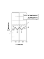
- FIG. 4 represents the volume change of the back pressure space 18 in the compressor 1 (compressor 10 having three vanes 14) of the present embodiment.
- the horizontal axis of the graph indicates the rotation angle of the compressor rotor 13, and the vertical axis indicates the total volume of the back pressure space 18.
- Curve A shows the volume change of the back pressure space 18 during operation of the compressor 1
- curve B shows the volume change of the back pressure space 18 when the compressor 1 is stopped.
- the compressor rotor 13 stops at a rotation angle at which the difference between the operating volume of the back pressure space 18 indicated by the curve A and the stopped volume of the back pressure space 18 indicated by the curve B becomes small.
- the inverter 30 (motor drive circuit 32) controls the rotation angle of the electric motor 20.
- the stator coil 21 of the electric motor 20 includes a first coil U1, U2, U3, a second coil V1, V2, V3, and a third coil W1, W2, W3. It is configured.
- the first coils U1, U2, and U3 are arranged at equal intervals in the circumferential direction, and supplied with a direct current Iu (see FIG. 7) to generate one magnetic force (N pole in the drawing) of the N and S poles. generate.
- the second coils V1, V2, and V3 are arranged between the first coils U1, U2, and U3 at equal intervals in the circumferential direction, and are supplied with a direct current Iv (see FIG. 7) to be N and S poles.
- Iv direct current
- the other magnetic force (S pole in the drawing) is generated.
- the third coils W1, W2, and W3 are disposed between the first coils U1, U2, and U3 and the second coils V1, V2, and V3 at equal intervals in the circumferential direction, and the direct current Iw (see FIG. 7). ) Is supplied to generate the other magnetic force (S pole in the drawing).
- the motor rotor 22 has six rotor magnets 25.
- Half of the rotor magnet 25 is arranged at equal intervals in the circumferential direction with the north pole facing outward.
- the other half of the rotor magnet 25 is disposed between the rotor magnets 25 with the S pole facing outward and the N pole facing outward as described above at equal intervals in the circumferential direction.
- the rotor magnet 25 with the north pole facing outward and the rotor magnet 25 with the south pole facing outward are alternately arranged.
- the rotor magnet 25 is arranged in a substantially hexagonal shape.
- the motor rotor 22 and the compressor rotor 13 are fixed so that the contact position between the vane 14 and the inner wall surface 15A of the cylinder chamber 15 coincides with the magnetic pole center of the corresponding rotor magnet 25 when the electric motor 20 is stopped. (See FIG. 2).
- the contact position between the vane 14 and the inner wall surface 15 ⁇ / b> A coincides with the magnetic pole center of the rotor magnet 25.
- one form is a form in which the contact position described above is arranged corresponding to the rotor magnet 25 having the south pole facing outward (this embodiment).
- the other form is a form in which the compressor rotor 13 is rotated by 60 ° [180 °] with respect to the motor rotor 22 from the rotational position shown in FIG. 2, and corresponds to the rotor magnet 25 having the N pole facing outward.
- the contact position described above is arranged.
- the contact position and the magnetic pole center coincide means that both the contact position and the magnetic pole center are on a straight line passing through the centers of the rotors 13 and 22 when viewed from the rotation axis direction of the rotors 13 and 22.
- the cylinder chamber 15 has an elliptical cross-sectional shape, when the contact position of the upper one vane 17 in FIG.
- the contact positions of the two vanes 17 slightly deviate from the magnetic pole center of the rotor magnet 25, but substantially coincide with each other.
- the cylinder chamber 15 having the inner wall of the ellipse is arranged so that the major axis direction of the ellipse is horizontal, and the above-described contact position is set at the uppermost position of the ellipse.
- the difference between the volume of the back pressure space 18 during operation of the compressor 1 and the volume of the back pressure space 18 when stopped is reduced (point P in the graph of FIG. 4). Therefore, in the present embodiment, each of the three vanes 17 can be located at the above-mentioned most contact position, and therefore, the graph of FIG. 4 shows that the motor rotor 22 (compressor rotor 13) is within a range of rotation (0 to 360 °). Three points P appear in
- the inverter 30 includes a power supply circuit unit 31, a motor drive circuit 32, and a motor stop control circuit 33.
- the power supply circuit unit 31 is connected to the motor drive circuit 32 and the motor stop control circuit 33 and supplies power to these circuits and the stator coil 21.
- the motor drive circuit 32 supplies power to the stator coil 21 and controls the electric motor 20 during normal operation of the compressor 1.
- the motor stop control circuit 33 controls the electric motor 20 when the compressor 1 is stopped.
- the motor stop control circuit 33 is composed of six control circuits 33A to 33F as shown in FIG.
- the motor stop control circuit 33 supplies power to the stator coil 21 that faces the magnetic poles of the rotor magnet 25. Specifically, when the electric motor 20 is stopped, the motor stop control circuit 33 is at a position corresponding to the position of the vane 17 in order to stop the vane 17 at the position where the volume difference becomes small (FIG. 2). Electric power is supplied to the first coils U1, U2, U3 so as to generate a magnetic pole (N pole) that attracts the rotor magnet 25 (with the S pole facing outward).
- a predetermined current for example, 10 A
- Predetermined current / 2 for example, 5 A
- the motor stop control circuit 33 When a stop command for the electric motor 20 is input (after the electric motor 20 starts to be stopped), the motor stop control circuit 33, after a predetermined time (for example, 10 seconds), the first coils U1, U2, U3, and the second coil V1. , V2, V3 and the third coils W1, W2, W3 are supplied with the DC currents Iu, Iv, Iw described above. As a result, the motor rotor 22 is stopped at the rotation angle (FIG. 2) where the volume difference described above becomes small.
- step S10 Motor Stop Control of Inverter 30
- the inverter 30 (motor drive circuit 32) decelerates the rotation of the electric motor 20 (step S10).
- step S10 the inverter 30 (motor stop control circuit 33) sets the stator of the electric motor 20 so as to reach a preset stop position of the motor rotor 22 (that is, the rotation angle at which the volume difference of the back pressure space 18 is reduced).
- the power supply to the coil 21 is controlled (step S20).
- the motor stop control circuit 33 sets a timer for measuring the time from the start of stopping of the electric motor 20 (step S21).
- the predetermined time for example, 10 seconds
- the predetermined time for example, 10 seconds
- the motor stop control circuit 33 determines whether or not the motor drive circuit 32 controls the electric motor 20 (step S22). When the motor drive circuit 32 controls the electric motor 20 (YES in step S22), the motor stop control circuit 33 controls the electric motor 20 in the normal operation mode of the compressor 1, and the process flow proceeds to step S25. Transition.
- step S22 when the motor drive circuit 32 does not control the electric motor 20 (NO in step S22), the motor stop control circuit 33 performs the predetermined time to continue the control of the rotation angle for stopping the motor rotor 22 (compressor rotor 13). It is determined whether or not elapses (step S23). If the predetermined time has not elapsed (NO in step S23), the motor stop control circuit 33 repeats the process of step S23 until the predetermined time has elapsed.
- step S23 when the predetermined time has elapsed (YES in step S23), electric power for stopping the motor rotor 22 at a preset stop position (that is, the rotation angle at which the volume difference becomes small) is supplied to the stator coil 21.
- the motor rotor 22 is stopped at the stop position described above by the magnetic force generated by the stator coil 21 (step S24).
- a direct current Iu for example, 10 A
- Iu that causes the stator teeth of the first coils U1, U2, and U3 to have an N pole
- a direct current Iv (for example, 5 A) that causes the stator teeth of the second coils V1, V2, and V3 to be S poles is supplied to the second coils V1, V2, and V3, and the third coils W1, W2, and so on.
- a DC current Iw (for example, 5 A) that causes the stator tooth of W3 to be the S pole is supplied to the third coils W1, W2, and W3 (see FIG. 7).
- the motor stop control circuit 33 resets the timer (step S25) and stops energization of the stator coil 21.
- the motor stop control circuit 33 applies the stator coil 21 with a magnetic force that attracts the rotor magnet 25 at a rotation angle at which the volume difference of the back pressure space 18 becomes small. Control power supply.
- the compressor rotor 13 (motor rotor 22) can be stopped at a rotation angle that suppresses the descent of the vane 14 in the vane groove 17 with the tip 14a of the vane 14 facing upward. Therefore, chattering when the compressor 1 is started can be prevented.
- a sensor for detecting the rotation angle of the motor rotor 22 is not required, and a coil spring for biasing the vane is not necessary. Therefore, the increase in assembly man-hours and the manufacturing cost can be reduced.
- the contact position between the tip 14a of the vane 14 and the inner wall surface 15A of the cylinder chamber 15 corresponds to the rotor magnet 25 corresponding to the rotor magnet 25 (this embodiment).
- the motor rotor 22 and the compressor rotor 13 are fixed so as to coincide with the magnetic pole center of the rotor magnet 25) with the S pole facing outward. Therefore, the tip 14a of the vane 14 is in reliable contact with the inner wall surface 15A of the cylinder chamber 15, and the lowering of the vane 14 with the tip 14a facing upward in the vane groove 17 can be more reliably prevented.
- the motor stop control circuit 33 supplies power to the first coils U1, U2, U3, the second coils V1, V2, V3 and the third coils W1, W2, W3 for a predetermined time from the start of stopping of the electric motor 20. Therefore, reverse rotation of the motor rotor 22 due to a pressure difference (difference between high pressure and low pressure) in the compressor 1 (cylinder chamber 15) can be prevented. As a result, the motor rotor 22 rotates until a predetermined time elapses, and the compressor rotor 13 can be stopped when the pressure inside the vane compressor 1 is equalized.
- the compressor 1 is arranged so that the elliptical major axis direction of the cylinder chamber 15 is horizontal when the vehicle is mounted. Therefore, the tip 14a of the vane 14 is easily brought into contact with the inner wall surface 15A of the cylinder chamber 15 when the compressor 1 is stopped, and the lowering of the vane 14 in the vane groove 17 can be reliably suppressed. Further, when the compressor is arranged in this manner, the volume difference of the back pressure space 18 described above is smaller, and chattering can be further prevented.
- the above embodiment can be modified as follows.
- the arrangement location of the rotor magnet 25 and the stator coil 21 is not limited to the above-described embodiment, and the rotor magnet 25 may be arranged as long as the volume difference of the back pressure space 18 of the compressor 1 is small. And the arrangement
- vanes 14 are provided, but the number of vanes 14 (vane grooves 17) is not limited to this. That is, the rotor magnet 25 does not need to be configured with three N poles and three S poles (total of six poles).
- the stator coil 21 includes three first coils U1, U2, U3, three It is not necessary to be constituted by the second coils V1, V2, V3 and the three second coils V1, V2, V3 (total nine slots).
- five vanes 14 (vane grooves 17) may be provided.
- the rotor magnet 25 includes five N poles and five S poles (10 poles in total).
- the stator coil 21 includes five first coils, five second coils, and five third coils (15 slots in total).
- the compressor 1 is arranged so that the elliptical long axis direction of the cylinder chamber 15 is horizontal when the vehicle is mounted.
- the elliptical long axis direction of the cylinder chamber 15 is vertical or oblique when mounted on the vehicle.
- the compressor 1 may be disposed.
Landscapes
- Engineering & Computer Science (AREA)
- Mechanical Engineering (AREA)
- General Engineering & Computer Science (AREA)
- Rotary Pumps (AREA)
- Applications Or Details Of Rotary Compressors (AREA)
Abstract
ベーン型圧縮機は、楕円内壁を有するシリンダ室が内部に形成されたシリンダブロック、周面上にベーン溝が形成されたコンプレッサロータ、及び、ベーン溝にそれぞれ収納されたベーンとを有する圧縮部と、ステータコイルを有するモータステータ、及び、ロータ磁石を有するモータロータを有する電動モータと、ステータコイルへの電力供給を制御してモータロータを回転させる駆動制御部と、を備えている。ベーンは、ベーン溝内の背圧空間に発生する背圧によってベーン溝から突出されて先端をシリンダ室の内壁に摺動接触させつつベーン溝内で往復動する。駆動制御部は、電動モータの停止時に、圧縮機運転時の背圧空間体積と圧縮機停止時の各背圧空間体積との差が小さくなる回転角度にコンプレッサロータを停止させる磁力を発生させるようにステータコイルに電力供給するモータ停止制御回路を備えている。上記圧縮機によれば、製造コストを抑制しつつ、チャタリングを防止することができる。
Description
本発明は、圧縮部[compression section]、電動モータ[electrical motor]及び駆動制御部[drive control unit]を備えるベーン型圧縮機[vane type compressor]に関する。
ベーン型圧縮機は、楕円内壁を有するシリンダ室が形成されたシリンダブロックと、シリンダ室内に回転可能に支持されて駆動部からの駆動力によって回転されるコンプレッサロータと、コンプレッサロータの外周から内部に向けて形成された複数のベーン溝内に収納された複数のベーンとを備えている。そして、コンプレッサロータが回転するとベーン溝内の背圧空間に発生する背圧によってベーンが突出され、ベーンは、その先端をシリンダ室の楕円内壁に摺動接触させるようにベーン溝内で往復動する。
通常運転中には、圧縮冷媒によって背圧空間内は中間圧となるので、ベーンはベーン溝から突出され、その先端がシリンダ室の楕円内壁に摺動接触しており、背圧空間の体積はほぼ一定に保たれている。一方、停止中には、圧縮機内の圧力は均一となり、ベーンをベーン溝から突出させるために必要な背圧がベーンに作用しない。このため、停止状態が続くと、先端が上方を向いているベーンは、自重によりベーン溝内の冷媒や油をベーン溝内壁とベーンとの間を通じて押し出しながらベーン溝内で降下する。従って、停止状態が続くと、背圧空間の体積は次第に小さくなる。
このような状態で圧縮機を起動すると、コンプレッサロータの回転による遠心力でベーンがベーン溝から突出しようとするが、背圧空間の体積が小さいので背圧空間が負圧となりベーンがベーン溝から突出しにくい。また、ベーン溝内壁とベーンとの間を通じて背圧空間に入り込む冷媒や油の量が少ないので、ベーンを突出させようとする遠心力が働いても、背圧空間が負圧のままとなってしまう。このため、ベーンの先端がシリンダ室の内壁面まで突出しきらず、ベーンとシリンダ室の内壁とが断続的に衝突することによる騒音(以下、チャタリングという)が生じる。
下記特許文献1は、チャタリングを防止する圧縮機を開示している。この圧縮機では、ベーン溝の底部にピンを支持する支持板が設けられ、ピンが支持板に固定されている。ピンの周面にはベーンを外方に付勢するコイルスプリングが配置されており、ベーンはベーン溝から突出する方向に常時付勢されている。これにより、停止状態でもベーンがベーン溝内で降下することがなく、起動時にはコイルスプリングの付勢力によってベーンがベーン溝から突出され、先端がシリンダ室の内壁と摺動接触するので、チャタリングが防止される。
しかし、上述した従来の圧縮機では、チャタリングは防止されるものの、コイルスプリングをさらに用いなければならず、組み付け工数や製造コストの増加という問題があった。
本発明の目的は、製造コストを低減させつつ、チャタリングを防止できるベーン型圧縮機を提供することにある。
本発明の特徴は、ベーン型圧縮機であって、楕円内壁を有するシリンダ室が内部に形成されたシリンダブロック、前記シリンダ室内に回転可能に支持されるとともに周面上に複数のベーン溝が形成されたコンプレッサロータ、及び、前記複数のベーン溝にそれぞれ収納されたベーンとを有する圧縮部と、複数のステータコイルを有するモータステータ、及び、前記モータステータへの電力供給によって発生された磁力が作用する複数のロータ磁石を有するモータロータを有する電動モータと、前記複数のステータコイルへの電力供給を制御して前記モータロータを回転させる駆動制御部と、を備え、前記複数のベーンは、前記コンプレッサロータの回転時に前記ベーン溝内の背圧空間に発生する背圧によって前記ベーン溝から突出されて先端を前記シリンダ室の前記内壁に摺動接触させつつ前記ベーン溝内でそれぞれ往復動し、前記駆動制御部が、前記電動モータの停止時に、前記圧縮機の運転時における前記各背圧空間の体積の総和と前記圧縮機の停止時における前記各背圧空間の体積の総和との差が小さくなる回転角度に前記コンプレッサロータを停止させる磁力を発生させるように前記ステータコイルに電力供給するモータ停止制御回路を備えている、ベーン型圧縮機を提供する。
上記特徴によれば、モータ停止制御回路は、上述した背圧空間の体積差が小さくなる回転角度で、ロータ磁石を引きつける磁力が発生するようにステータコイルへの電力供給を制御する。この結果、ベーンの先端が上方を向いているベーンのベーン溝内での降下を抑止する回転角度でコンプレッサロータを停止させることができる。従って、圧縮機の起動時のチャタリングを防止できる。また、モータロータの回転角度を検出するセンサーが不要で、ベーンを付勢するコイルスプリングも必要がない。従って、組付工数の増大や製造コストを低減できる。
ここで、前記回転角度における前記複数のベーンの前記先端と前記シリンダ室の前記内壁との接触位置が、前記複数のロータ磁石のうちの対応するロータ磁石の磁極中心とそれぞれ一致するように、前記モータロータと前記コンプレッサロータとが固定されている、ことが好ましい。このようにすれば、ベーンの先端はシリンダ室の内壁面に確実に接し、先端が上方を向いているベーンのベーン溝内での降下をより確実に抑止できる。
また、前記ステータコイルが、周方向に等間隔に配置された、直流電流の供給によってN極及びS極の一方の磁力を発生させる三つの第1コイルと、周方向で等間隔に前記第1コイルの各間にそれぞれ配置された、直流電流の供給によってN極及びS極の他方の磁力を発生させる三つの第2コイルと、周方向に等間隔に前記第1コイルと前記第2コイルとの各間にそれぞれ配置された、直流電流の供給によって前記他方の磁力を発生させる三つの第3コイルと、によって構成され、前記モータ停止制御回路が、前記電動モータの停止時に、前記第2コイルに供給される前記直流電流と前記第3コイルに供給される前記直流電流とが等しくなるように、前記第1コイル、前記第2コイル及び前記第3コイルに電力供給する、ことが好ましい。このようにすれば、ステータコイルが(第1~第3コイルの)各相毎に三つのコイルで構成される場合に特に有効となり、製造コストの低減を図りつつ、チャタリングを防止できる。
ここで、前記モータ停止制御回路が、前記電動モータの停止開始から所定時間、前記第1コイル、前記第2コイル及び前記第3コイルに電力供給することが好ましい。このようにすれば、圧縮機(シリンダ室)内の圧力差(高圧と低圧との差)によるモータロータの逆回転を防止できる。この結果、所定時間が経過するまでモータロータが回転し、圧縮機内が均圧となった際にコンプレッサロータを停止させることができる。
また、前記圧縮機が、車両の空調システム内の冷媒を圧縮し、前記シリンダ室の楕円長径方向が水平となるように、前記圧縮機が前記車両に搭載される、ことが好ましい。このようにすれば、圧縮機の停止時にベーンの先端がシリンダ室の内壁面と接触し易くなり、ベーンのベーン溝内での降下を確実に抑止できる。また、このように圧縮機を配設すると、上述した背圧空間18の体積差がより小さくなるので、チャタリングをより一層防止できる。
ベーン型圧縮機の実施形態について、図面を参照しつつ説明する。具体的には、(1)ベーン型圧縮機1の構成、(2)圧縮部[compression section]10の詳細、(3)電動モータ20の詳細、(4)インバーター30の詳細、(5)動作及び効果、(6)変形例について説明する。なお、図面において、寸法比率などは現実のものとは異なる場合がある。したがって、具体的な寸法などは以下の説明を参酌して判断されるべきである。また、図面間においても寸法比率などが異なる場合がある。
ベーン型圧縮機1は、車両の空調システムに用いられ、冷媒を圧縮する。圧縮機1は、冷媒を圧縮する圧縮部10と、圧縮部10に組み付けられる電動モータ20と、空調システムの熱負荷変化に応じて電動モータ20の回転数を制御するインバーター30(駆動制御部)とを備えている。
圧縮部10は、楕円内壁を有するシリンダ室15が形成されたシリンダブロック11と、シリンダ室15内に回転可能に支持され、複数のベーン溝17が形成されたコンプレッサロータ13と、ベーン溝17にそれぞれ収納された複数のベーン14とを備えている。電動モータ20は、ステータコイル21への電力供給によって磁力を発生するモータステータ21Aと、ロータ磁石25を有するとともに発生された磁力で回転されるモータロータ22とを備えている。インバーター30は、ステータコイル21に電力を供給するとともに電動モータ20を制御する。なお、コンプレッサロータ13の回転時には、ベーン14の基端側の背圧空間18に発生する背圧でベーン14はベーン溝17から突出され、ベーン14は、その先端14aをシリンダ室15の内壁面15Aに摺動接触させるようにベーン溝17内で往復動する。
(1)ベーン型圧縮機1の構成
図1に示されるように、圧縮機1は、円筒状のハウジング50を備えている。ハウジング50は、インバーター30を収容するフロントハウジング50Fと、圧縮部10を収容するミドルハウジング50Mと、電動モータ20を収容するリアハウジング50Rとによって構成されている。フロントハウジング50F、ミドルハウジング50M及びリアハウジング50Rはボルト等により互いに結合され、ハウジング50の内部に密閉された空間が形成される。
図1に示されるように、圧縮機1は、円筒状のハウジング50を備えている。ハウジング50は、インバーター30を収容するフロントハウジング50Fと、圧縮部10を収容するミドルハウジング50Mと、電動モータ20を収容するリアハウジング50Rとによって構成されている。フロントハウジング50F、ミドルハウジング50M及びリアハウジング50Rはボルト等により互いに結合され、ハウジング50の内部に密閉された空間が形成される。
圧縮部10は、主として、円筒状のシリンダブロック11と、シリンダブロック11の両側に設けられた一対のサイドブロック12と、複数のベーン溝17が形成されたコンプレッサロータ13と、ベーン溝17にそれぞれ収容された複数のベーン14とによって構成されている。
電動モータ20は、主として、リアハウジング50Rの内周面に沿って複数配置されたステータコイル21への電力供給によって磁力を発生するモータステータ21Aと、発生された磁力で回転されるモータロータ22と、モータロータ22の中心と固定された回転軸23とによって構成されている。
モータロータ22は、回転軸23に圧入されて固定されている。回転軸23の一端は、ベアリング24aによってを介して、リアハウジング50Rに回転自在に支持されている。回転軸23の他端は、ベアリング24bを介して、電動モータ20とサイドブロック12の間に配置された仕切壁19に回転自在に支持されている。また、コンプレッサロータ13を支持するロータ軸16が、回転軸23に連結されている。電動モータ20の回転駆動力は、回転軸23からロータ軸16を介してコンプレッサロータ13に伝達され、コンプレッサロータ13が回転する。
なお、本実施形態の電動モータ20は、そのモータロータ22の回転角度を検出することができる。センサー(図示せず)によってモータロータ22の回転角度が検出され、この検出結果がインバーター30に伝達される。センサーとしては、例えば、モータロータ22に組み付けられた磁石の位置を検出することでモータロータ22の回転角度を検出するセンサーが挙げられる。
圧縮機1の停止時には、コンプレッサロータ13(回転軸23)は所定回転角度で停止される。所定回転角度は、運転時の背圧空間18の体積の総和と停止時の背圧空間18の体積の総和との差が小さくなる回転角度である。なお、背圧空間18の体積変化については、後述する。
インバーター30は、フロントハウジング50Fに収容された駆動回路によって構成されている。インバーター30は、モータロータ22の回転角度の検出結果に基づいて、電動モータ20のステータコイル21への電力供給を制御する。インバーター30には、モータ停止制御回路33(図6参照)が設けられている。モータ停止制御回路33は、モータロータ22の回転角度の検出結果に基づいて、回転軸23を上述した所定回転角度で停止させるように、ステータコイル21への電力供給を制御する。
(2)圧縮部10の詳細
圧縮部10の詳細について、図1~図3を参照しつつ説明する。なお、圧縮部10は、図2では電動モータ20との関係を分かりやすくするために二点差線で示されており、図3に単独で断面図で示されている。また、電動モータ20は、図2では圧縮部10との関係を分かりやすくするために断面ハッチングが省略されており、図4に単独で断面図で示されている。
圧縮部10の詳細について、図1~図3を参照しつつ説明する。なお、圧縮部10は、図2では電動モータ20との関係を分かりやすくするために二点差線で示されており、図3に単独で断面図で示されている。また、電動モータ20は、図2では圧縮部10との関係を分かりやすくするために断面ハッチングが省略されており、図4に単独で断面図で示されている。
(2.1)圧縮部10の構成
図1~図3に示されるように、圧縮部10のシリンダブロック11の内部には、滑らかな楕円内壁面15Aを有するシリンダ室15が形成されている。シリンダ室15は、一対のサイドブロック12によってその両側が覆われている。また、シリンダ室15は、圧縮機1の車両搭載時に、その楕円長径方向が水平となるように配設されている。シリンダ室15内の中心にコンプレッサロータ13が配置されている。
図1~図3に示されるように、圧縮部10のシリンダブロック11の内部には、滑らかな楕円内壁面15Aを有するシリンダ室15が形成されている。シリンダ室15は、一対のサイドブロック12によってその両側が覆われている。また、シリンダ室15は、圧縮機1の車両搭載時に、その楕円長径方向が水平となるように配設されている。シリンダ室15内の中心にコンプレッサロータ13が配置されている。
回転軸23に連結されたロータ軸16がシリンダ室15内を貫通しており、コンプレッサロータ13はロータ軸16に固定されている。電動モータ20の回転駆動力によってロータ軸16が回転されると、コンプレッサロータ13がシリンダ室15内で回転する。
図3に示されるように、コンプレッサロータ13には、外周面から内部に向けて3つのベーン溝17が周方向に等間隔に形成されている。各ベーン溝17は、板状のベーン14が往復動可能に収容されるベーン可動溝17bと、ベーン可動溝17bに連通すると共に一対のサイドブロック12の冷媒通路と連通する円形断面を有する圧力溝17cとによって構成されている。ベーン可動溝17b及び圧力溝17cは、ロータ軸16に沿って延設されている。また、ベーン溝17の底17aとベーン14の基端14bとの間に、冷媒(及び潤滑油、以下、単に冷媒という)が供給される背圧空間18が形成される。背圧空間18の体積は、ベーン14の突出量によって変化する。
ベーン14は、コンプレッサロータ13の回転による遠心力と背圧空間18に供給された高圧冷媒の圧力によってベーン溝17から突出され、その先端14aをシリンダ室15の内壁面15Aに摺動接触させつつ往復動する。コンプレッサロータ13がロータ軸16を介して電動モータ20によって回転されると、内壁面15Aとベーン14との間に供給された冷媒が圧縮される。
(2.2)背圧空間18の体積変化
背圧空間18の体積の変化(正確には、背圧空間18の体積の総和の変化、以下単に、体積変化という)、具体的には、圧縮機1の運転時の体積変化、及び、圧縮機1の停止時の体積変化について、図4を参照しつつ説明する。
背圧空間18の体積の変化(正確には、背圧空間18の体積の総和の変化、以下単に、体積変化という)、具体的には、圧縮機1の運転時の体積変化、及び、圧縮機1の停止時の体積変化について、図4を参照しつつ説明する。
図4に示されるグラフは、本実施形態の圧縮機1(ベーン14が3枚の圧縮部10)における背圧空間18の体積変化を表している。グラフの横軸はコンプレッサロータ13の回転角度を示し、縦軸は背圧空間18の体積の総和を示している。曲線Aは、圧縮機1の運転時の背圧空間18の体積変化を示し、曲線Bは、圧縮機1の停止時の背圧空間18の体積変化を示している。
曲線Aで示されるように、圧縮機1の運転時では、全てのベーン14の先端14aが内壁面15Aと摺動接触している。このため、背圧空間18の体積変化は少なく、コンプレッサロータ13の回転角度に対してほぼ一定の値となる。
一方、曲線Bで示されるように、圧縮機1の停止時では、コンプレッサロータ13が停止している回転角度によって、背圧空間18の体積は大きく変化する。曲線B上の点Qで示される回転角度(約40°、約150°、約260°・・・)でコンプレッサロータ13が停止すると、一つのベーン14が上方を向いた位置に停止する。この結果、そのベーン14が自重によってベーン溝17内で降下し、背圧空間18の体積が減少する(運転時の背圧空間18の体積との差が大きい[最大となる])。
また、曲線B上の点Pで示される回転角度(約90°、約210°、約320°・・・)では、ベーン14が自重で降下する距離が少ない位置でコンプレッサロータ13が停止される。従って、背圧空間18の体積はほとんど減少しない(運転時の背圧空間18の体積との差が小さい[最小となる])。
これらの曲線A及び曲線Bから、圧縮機1の停止時におけるコンプレッサロータ13の回転角度(回転位置)に応じて背圧空間18の体積が大きく変化することが分かる。圧縮機1の停止時におけるコンプレッサロータ13の停止位置を所定回転角度に設定することで、背圧空間18の体積の減少を抑制できる。
このため、本実施形態では、曲線Aで示される背圧空間18の運転時体積と曲線Bで示される背圧空間18の停止時体積との差が小さくなる回転角度でコンプレッサロータ13が停止するように、インバーター30(モータ駆動回路32)が電動モータ20の回転角度を制御する。
(3)電動モータ20の詳細
電動モータ20の詳細について、図2及び図5を参照しつつ説明する。
電動モータ20の詳細について、図2及び図5を参照しつつ説明する。
(3.1)ステータコイル21
図2及び図5に示されるように、電動モータ20のステータコイル21は、第1コイルU1,U2,U3と、第2コイルV1,V2,V3と、第3コイルW1,W2,W3とによって構成されている。
図2及び図5に示されるように、電動モータ20のステータコイル21は、第1コイルU1,U2,U3と、第2コイルV1,V2,V3と、第3コイルW1,W2,W3とによって構成されている。
第1コイルU1,U2,U3は、周方向に等間隔に配置されており、直流電流Iu(図7参照)が供給されてN極及びS極の一方の磁力(図面では、N極)を発生させる。
第2コイルV1,V2,V3は、周方向に等間隔に第1コイルU1,U2,U3の各間に配置されており、直流電流Iv(図7参照)が供給されてN極及びS極の他方の磁力(図面では、S極)を発生させる。
第3コイルW1,W2,W3は、周方向に等間隔に第1コイルU1,U2,U3と第2コイルV1,V2,V3との各間に配置されており、直流電流Iw(図7参照)が供給されて前記他方の磁力(図面では、S極)を発生させる。
ステータコイル21では、第1コイルU1(N極)を上方基準位置として、U1(N極),V1(S極),W1(S極),U2(N極),V2(S極),W2(S極),U3(N極),V3(S極),W3(S極)の順に時計回りに配列されている。電動モータ20の駆動時には、上述したUVW相のコイルへの電力供給を順次切り替えることで、モータステータ21AのUVW相のステータティースの磁極が順次切り替えられて、モータロータ22が回転される。
(3.2)モータロータ22
図2及び図5に示されるように、モータロータ22は、六つのロータ磁石25を有している。ロータ磁石25の半分は、周方向に等間隔に、外方にN極を向けて配置されている。ロータ磁石25の残りの半分は、周方向に等間隔に、外方にS極を向けて、上述した外方にN極を向けたロータ磁石25の各間に配置されている。外方にN極を向けたロータ磁石25と外方にS極を向けたロータ磁石25とは交互に配置されている。本実施形態では、ロータ磁石25は、ほぼ六角形状に配置されている。
図2及び図5に示されるように、モータロータ22は、六つのロータ磁石25を有している。ロータ磁石25の半分は、周方向に等間隔に、外方にN極を向けて配置されている。ロータ磁石25の残りの半分は、周方向に等間隔に、外方にS極を向けて、上述した外方にN極を向けたロータ磁石25の各間に配置されている。外方にN極を向けたロータ磁石25と外方にS極を向けたロータ磁石25とは交互に配置されている。本実施形態では、ロータ磁石25は、ほぼ六角形状に配置されている。
電動モータ20の停止時におけるベーン14とシリンダ室15の内壁面15Aとの接触位置が、対応するロータ磁石25の磁極中心とそれぞれ一致するように、モータロータ22とコンプレッサロータ13とが固定されている(図2参照)。三つのベーン14が設けられ、かつ、六つのロータ磁石25が設けられる場合、ベーン14と内壁面15Aとの接触位置がロータ磁石25の磁極中心と一致する形態は二種類存在する。一方の形態は、図2に示されるように、外方にS極を向けているロータ磁石25に対応して上述した接触位置が配置される形態である(本実施形態)。他方の形態は、コンプレッサロータ13が図2に示される回転位置からモータロータ22に対して60°[180°]回転された形態であり、外方にN極を向けているロータ磁石25に対応して上述した接触位置が配置される形態である。
なお、「接触位置と磁極中心とが一致する」とは、ロータ13及び22の回転軸方向から見て、ロータ13及び22の中心を通る直線上に接触位置と磁極中心との両方があることを言う。また、厳密に言えば、シリンダ室15は楕円断面形状を有しているので、図2の上方の一つのベーン17の接触位置がロータ磁石25の磁極中心と正確に一致している場合、下方の二つのベーン17の接触位置はロータ磁石25の磁極中心とはごく僅かにずれるが、実質的に一致している。
また、本実施形態では、楕円内壁を有するシリンダ室15の楕円長径方向が水平となるように配設され、かつ、上述した接触位置が楕円の最上位置に設定されているので、図2に示される形態で、圧縮機1の運転時における背圧空間18の体積と停止時における背圧空間18の体積との差が小さくなる(図4のグラフ中の点P)。従って、本実施形態では、三つの各ベーン17が上述した最上接触位置に位置し得るので、図4のグラフには、モータロータ22(コンプレッサロータ13)の一回転の範囲(0~360°)内に三つの点Pが現れる。
(4)インバーター30の詳細
インバーター30の詳細について、図6~図8を参照しつつ説明する。
インバーター30の詳細について、図6~図8を参照しつつ説明する。
(4.1)インバーター30の構成
図6に示されるように、インバーター30は、電源回路部31と、モータ駆動回路32と、モータ停止制御回路33とによって構成されている。
図6に示されるように、インバーター30は、電源回路部31と、モータ駆動回路32と、モータ停止制御回路33とによって構成されている。
電源回路部31は、モータ駆動回路32及びモータ停止制御回路33に接続されており、これらの回路及びステータコイル21に電力供給する。モータ駆動回路32は、ステータコイル21に電力供給して、圧縮機1の通常運転時に電動モータ20を制御する。モータ停止制御回路33は、圧縮機1の停止時に電動モータ20を制御する。
モータ停止制御回路33は、図7に示されるように、6つの制御回路33A~33Fで構成されている。モータ停止制御回路33は、ロータ磁石25の磁極に対向するステータコイル21に電力供給する。具体的には、電動モータ20の停止時には、モータ停止制御回路33は、上述した体積差が小さくなる位置(図2)にベーン17を停止させるために、ベーン17の位置に対応する位置にある(外方にS極を向けている)ロータ磁石25を引きつける磁極(N極)を発生させるように第1コイルU1,U2,U3に電力供給する。
即ち、電動モータ20の停止時には、モータ停止制御回路33は、直流電流Ivと直流電流Iwとが等しくなる(Iv=Iw)ように、第1コイルU1,U2,U3、第2コイルV1,V2,V3及び第3コイルW1,W2,W3に電力供給する。具体的には、モータ停止制御回路33は、第1コイルU1,U2,U3に所定電流(例えば、10A)を供給する場合は、第2コイルV1,V2,V3及び第3コイルW1,W2,W3にそれぞれ(上記所定電流/2)(例えば、5A)を供給する。
モータ停止制御回路33は、電動モータ20の停止指令が入力されると(電動モータ20の停止開始後)所定時間(例えば、10秒)後に、第1コイルU1,U2,U3、第2コイルV1,V2,V3及び第3コイルW1,W2,W3に上述した直流電流Iu,Iv,Iwを供給する。この結果、モータロータ22は上述した体積差が小さくなる回転角度(図2)で停止される。
(4.2)インバーター30のモータ停止制御
図8に示されるように、電動モータ20の停止指令に基づいて、インバーター30(モータ駆動回路32)は、電動モータ20の回転を減速させる(ステップS10)。次いで、インバーター30(モータ停止制御回路33)は、予め設定されたモータロータ22の停止位置(すなわち、上述した背圧空間18の体積差が小さくなる回転角度)となるように、電動モータ20のステータコイル21への電力供給を制御する(ステップS20)。
図8に示されるように、電動モータ20の停止指令に基づいて、インバーター30(モータ駆動回路32)は、電動モータ20の回転を減速させる(ステップS10)。次いで、インバーター30(モータ停止制御回路33)は、予め設定されたモータロータ22の停止位置(すなわち、上述した背圧空間18の体積差が小さくなる回転角度)となるように、電動モータ20のステータコイル21への電力供給を制御する(ステップS20)。
具体的には、図9に示されるように、モータ停止制御回路33は、電動モータ20の停止開始からの時間を計測するタイマをセットする(ステップS21)。タイマによって、停止開始からステータコイル21への電力供給を止めるまでの上述した所定時間(例えば、10秒)が計測される。
次いで、モータ停止制御回路33は、モータ駆動回路32が電動モータ20を制御するか否かを判断する(ステップS22)。なお、モータ駆動回路32が電動モータ20を制御する場合(ステップS22でYES)、モータ停止制御回路33が圧縮機1の通常運転モードで電動モータ20を制御するために、処理流れはステップS25に移行する。
一方、モータ駆動回路32が電動モータ20を制御しない場合(ステップS22でNO)、モータロータ22(コンプレッサロータ13)を停止する回転角度の制御を続行するべく、モータ停止制御回路33は、上記所定時間が経過したか否かを判断する(ステップS23)。所定時間が経過していない場合(ステップS23でNO)、モータ停止制御回路33は、所定時間が経過するまでステップS23の処理を繰り返す。
一方、所定時間が経過した場合(ステップS23でYES)、モータロータ22を予め設定された停止位置(すなわち、上述した体積差が小さくなる回転角度)に停止させるための電力がステータコイル21に供給され、ステータコイル21が発生する磁力によって、モータロータ22が上述した停止位置で停止される(ステップS24)。具体的には、第1コイルU1,U2,U3のステータティースがN極となるような直流電流Iu(例えば、10A)が、第1コイルU1,U2,U3に供給される。また、第2コイルV1,V2,V3のステータティースがS極となるような直流電流Iv(例えば、5A)が第2コイルV1,V2,V3に供給されると共に、第3コイルW1,W2,W3のステータティースがS極となるような直流電流Iw(例えば、5A)が第3コイルW1,W2,W3に供給される(図7参照)。次いで、モータ停止制御回路33は、タイマをリセットし(ステップS25)、ステータコイル21への通電を停止する。
(5)作用・効果
本実施形態では、モータ停止制御回路33は、上述した背圧空間18の体積差が小さくなる回転角度で、ロータ磁石25を引きつける磁力が発生するようにステータコイル21への電力供給を制御する。この結果、ベーン14の先端14aが上方を向いているベーン14のベーン溝17内での降下を抑止する回転角度でコンプレッサロータ13(モータロータ22)を停止させることができる。従って、圧縮機1の起動時のチャタリングを防止できる。また、モータロータ22の回転角度を検出するセンサーが不要で、ベーンを付勢するコイルスプリングも必要がない。従って、組付工数の増大や製造コストを低減できる。
本実施形態では、モータ停止制御回路33は、上述した背圧空間18の体積差が小さくなる回転角度で、ロータ磁石25を引きつける磁力が発生するようにステータコイル21への電力供給を制御する。この結果、ベーン14の先端14aが上方を向いているベーン14のベーン溝17内での降下を抑止する回転角度でコンプレッサロータ13(モータロータ22)を停止させることができる。従って、圧縮機1の起動時のチャタリングを防止できる。また、モータロータ22の回転角度を検出するセンサーが不要で、ベーンを付勢するコイルスプリングも必要がない。従って、組付工数の増大や製造コストを低減できる。
また、コンプレッサロータ13(モータロータ22)が停止される回転角度において、ベーン14の先端14aとシリンダ室15の内壁面15Aとの接触位置が、ロータ磁石25のうちの対応するロータ磁石25(本実施形態では、外方にS極を向けたロータ磁石25)の磁極中心とそれぞれ一致するように、モータロータ22とコンプレッサロータ13とが固定されている。従って、ベーン14の先端14aはシリンダ室15の内壁面15Aに確実に接し、先端14aが上方を向いているベーン14のベーン溝17内での降下をより確実に抑止できる。
また、ステータコイル21は、第1コイルU1,U2,U3、第2コイルV1,V2,V3及び第3コイルW1,W2,W3によって構成され、モータ停止制御回路33は、電動モータ20の停止時に、直流電流Ivと直流電流Iwとが等しくなる(Iv=Iw)ように、第1コイルU1,U2,U3、第2コイルV1,V2,V3及び第3コイルW1,W2,W3に電力供給する。従って、ステータコイル21が各相毎に三つのコイルで構成される場合に特に有効となり、製造コストの低減を図りつつ、チャタリングを防止できる。
また、モータ停止制御回路33は、電動モータ20の停止開始から所定時間、第1コイルU1,U2,U3、第2コイルV1,V2,V3及び第3コイルW1,W2,W3に電力供給する。従って、圧縮機1(シリンダ室15)内の圧力差(高圧と低圧との差)によるモータロータ22の逆回転を防止できる。この結果、所定時間が経過するまでモータロータ22が回転し、ベーン型圧縮機1内が均圧となった際にコンプレッサロータ13を停止させることができる。
また、シリンダ室15の楕円長径方向が車両搭載時に水平となるように、圧縮機1が配設された。従って、圧縮機1の停止時にベーン14の先端14aがシリンダ室15の内壁面15Aと接触し易くなり、ベーン14のベーン溝17内での降下を確実に抑止できる。また、このように圧縮機を配設すると、上述した背圧空間18の体積差がより小さくので、チャタリングをより一層防止できる。
(6)変形例
上述したように、上記実施形態によって本発明を開示したが、この開示の一部をなす論述及び図面は、本発明を限定するものであると理解すべきではない。この開示から当業者には様々な代替実施の形態、実施例及び運用技術が明らかとなる。
上述したように、上記実施形態によって本発明を開示したが、この開示の一部をなす論述及び図面は、本発明を限定するものであると理解すべきではない。この開示から当業者には様々な代替実施の形態、実施例及び運用技術が明らかとなる。
例えば、上記実施形態は次のように変形可能である。具体的には、ロータ磁石25やステータコイル21の配置箇所については、上記実施形態に限定されず、圧縮機1の上述した背圧空間18の体積差が小さくなる配置であれば、ロータ磁石25やステータコイル21の配置箇所は変更できる。
また、上記実施形態では、三つのベーン14(ベーン溝17)が設けられたが、ベーン14(ベーン溝17)の数はこれに限定されない。すなわち、ロータ磁石25は、三つのN極及び三つのS極(計六極)で構成される必要はなく、同様に、ステータコイル21も、三つの第1コイルU1,U2,U3、三つの第2コイルV1,V2,V3及び三つの第2コイルV1,V2,V3(計九スロット)によって構成される必要はない。例えば、五つのベーン14(ベーン溝17)が設けられてもよい。この場合、ロータ磁石25は、五つのN極及び五つのS極(計10極)によって構成される。また、ステータコイル21は、五つの第1コイルと、五つの第2コイルと、五つの第3コイル(計15スロット)によって構成される。
また、上記実施形態では、シリンダ室15の楕円長径方向が車両搭載時に水平となるように、圧縮機1が配設されたが、シリンダ室15の楕円長径方向が車両搭載時に鉛直や斜めとなるように圧縮機1が配設されてもよい。
このように、本発明は、ここでは記載していない様々な実施の形態などを含むことは勿論である。したがって、本発明の技術的範囲は、上述の説明から妥当な特許請求の範囲に係る発明特定事項によってのみ定められる。
Claims (5)
- ベーン型圧縮機であって、
楕円内壁を有するシリンダ室が内部に形成されたシリンダブロック、前記シリンダ室内に回転可能に支持されるとともに周面上に複数のベーン溝が形成されたコンプレッサロータ、及び、前記複数のベーン溝にそれぞれ収納されたベーンとを有する圧縮部と、
複数のステータコイルを有するモータステータ、及び、前記モータステータへの電力供給によって発生された磁力が作用する複数のロータ磁石を有するモータロータを有する電動モータと、
前記複数のステータコイルへの電力供給を制御して前記モータロータを回転させる駆動制御部と、を備え、
前記複数のベーンは、前記コンプレッサロータの回転時に前記ベーン溝内の背圧空間に発生する背圧によって前記ベーン溝から突出されて先端を前記シリンダ室の前記内壁に摺動接触させつつ前記ベーン溝内でそれぞれ往復動し、
前記駆動制御部が、前記電動モータの停止時に、前記圧縮機の運転時における前記各背圧空間の体積の総和と前記圧縮機の停止時における前記各背圧空間の体積の総和との差が小さくなる回転角度に前記コンプレッサロータを停止させる磁力を発生させるように前記ステータコイルに電力供給するモータ停止制御回路を備えている、ベーン型圧縮機。 - 請求項1に記載のベーン型圧縮機であって、
前記回転角度における前記複数のベーンの前記先端と前記シリンダ室の前記内壁との接触位置が、前記複数のロータ磁石のうちの対応するロータ磁石の磁極中心とそれぞれ一致するように、前記モータロータと前記コンプレッサロータとが固定されている、ベーン型圧縮機。 - 請求項1又は2に記載のベーン型圧縮機であって、
前記ステータコイルが、周方向に等間隔に配置された、直流電流の供給によってN極及びS極の一方の磁力を発生させる三つの第1コイルと、周方向で等間隔に前記第1コイルの各間にそれぞれ配置された、直流電流の供給によってN極及びS極の他方の磁力を発生させる三つの第2コイルと、周方向に等間隔に前記第1コイルと前記第2コイルとの各間にそれぞれ配置された、直流電流の供給によって前記他方の磁力を発生させる三つの第3コイルと、によって構成され、
前記モータ停止制御回路が、前記電動モータの停止時に、前記第2コイルに供給される前記直流電流と前記第3コイルに供給される前記直流電流とが等しくなるように、前記第1コイル、前記第2コイル及び前記第3コイルに電力供給する、ベーン型圧縮機。 - 請求項3に記載のベーン型圧縮機であって、
前記モータ停止制御回路は、前記電動モータの停止開始から所定時間、前記第1コイル、前記第2コイル及び前記第3コイルに電力供給する、ベーン型圧縮機。 - 請求項1~4の何れかに記載のベーン型圧縮機であって、
前記圧縮機が、車両の空調システム内の冷媒を圧縮し、
前記シリンダ室の楕円長径方向が水平となるように、前記圧縮機が前記車両に搭載される、ベーン型圧縮機。
Applications Claiming Priority (2)
| Application Number | Priority Date | Filing Date | Title |
|---|---|---|---|
| JP2011142913A JP5589975B2 (ja) | 2011-06-28 | 2011-06-28 | ベーン型圧縮機 |
| JP2011-142913 | 2011-06-28 |
Publications (1)
| Publication Number | Publication Date |
|---|---|
| WO2013002183A1 true WO2013002183A1 (ja) | 2013-01-03 |
Family
ID=47424075
Family Applications (1)
| Application Number | Title | Priority Date | Filing Date |
|---|---|---|---|
| PCT/JP2012/066164 Ceased WO2013002183A1 (ja) | 2011-06-28 | 2012-06-25 | ベーン型圧縮機 |
Country Status (2)
| Country | Link |
|---|---|
| JP (1) | JP5589975B2 (ja) |
| WO (1) | WO2013002183A1 (ja) |
Cited By (1)
| Publication number | Priority date | Publication date | Assignee | Title |
|---|---|---|---|---|
| CN105673487A (zh) * | 2016-01-28 | 2016-06-15 | 珠海凌达压缩机有限公司 | 空调器、压缩机及其转子 |
Citations (3)
| Publication number | Priority date | Publication date | Assignee | Title |
|---|---|---|---|---|
| JP2009156088A (ja) * | 2007-12-25 | 2009-07-16 | Calsonic Kansei Corp | ベーン形圧縮機 |
| JP2010084522A (ja) * | 2008-09-29 | 2010-04-15 | Calsonic Kansei Corp | ベーンロータリー圧縮機 |
| JP2011106278A (ja) * | 2009-11-12 | 2011-06-02 | Calsonic Kansei Corp | コンプレッサ |
-
2011
- 2011-06-28 JP JP2011142913A patent/JP5589975B2/ja not_active Expired - Fee Related
-
2012
- 2012-06-25 WO PCT/JP2012/066164 patent/WO2013002183A1/ja not_active Ceased
Patent Citations (3)
| Publication number | Priority date | Publication date | Assignee | Title |
|---|---|---|---|---|
| JP2009156088A (ja) * | 2007-12-25 | 2009-07-16 | Calsonic Kansei Corp | ベーン形圧縮機 |
| JP2010084522A (ja) * | 2008-09-29 | 2010-04-15 | Calsonic Kansei Corp | ベーンロータリー圧縮機 |
| JP2011106278A (ja) * | 2009-11-12 | 2011-06-02 | Calsonic Kansei Corp | コンプレッサ |
Cited By (2)
| Publication number | Priority date | Publication date | Assignee | Title |
|---|---|---|---|---|
| CN105673487A (zh) * | 2016-01-28 | 2016-06-15 | 珠海凌达压缩机有限公司 | 空调器、压缩机及其转子 |
| CN105673487B (zh) * | 2016-01-28 | 2018-09-07 | 珠海凌达压缩机有限公司 | 空调器、压缩机及其转子 |
Also Published As
| Publication number | Publication date |
|---|---|
| JP5589975B2 (ja) | 2014-09-17 |
| JP2013011184A (ja) | 2013-01-17 |
Similar Documents
| Publication | Publication Date | Title |
|---|---|---|
| JP5835928B2 (ja) | 電動モータおよびそれを用いた電動圧縮機 | |
| US8169117B2 (en) | Brushless motor for fluid pump and fluid pump using the motor | |
| JP6360536B2 (ja) | スクロールポンプ及びスクロールポンプの運転の為の方法 | |
| JP2014173436A (ja) | スクロール型圧縮機 | |
| US20150204327A1 (en) | Integrated Brushless Direct Current Motor and Lift Pump | |
| JP2013241907A (ja) | バキュームポンプ | |
| JP5929876B2 (ja) | 駆動制御装置、および、これを用いた燃料ポンプ | |
| WO2013002183A1 (ja) | ベーン型圧縮機 | |
| JP5058896B2 (ja) | 電動遠心ポンプ | |
| CN102844571B (zh) | 叶片型压缩机 | |
| JP2014077402A (ja) | ベーン型圧縮機 | |
| KR20120096268A (ko) | 차량용 전동식압축기의 구동방법 | |
| JP2005315243A (ja) | 燃料ポンプおよびそれを用いた燃料供給装置 | |
| KR101936096B1 (ko) | 차량용 전동 압축기 | |
| JP6074203B2 (ja) | スクロール型圧縮機 | |
| JP2006280088A (ja) | ブラシレスモータ | |
| CN110985391B (zh) | 一种电动涡旋压缩机动态驱动扭矩测量装置及测量方法 | |
| JP5972737B2 (ja) | 電動ウォーターポンプ | |
| JP2014173514A (ja) | 電動ウォーターポンプ | |
| JPWO2015163257A1 (ja) | ロータリ式圧縮機、およびこれを搭載したヒートポンプ装置 | |
| JP2008022666A (ja) | モータおよび圧縮機 | |
| KR20110128681A (ko) | 전동식스크롤압축기 전동기의 구조 | |
| JP2016086467A (ja) | 駆動制御装置、及び、モータ駆動システム | |
| JP2012193722A (ja) | 電動ポンプ | |
| JP2009050123A (ja) | ステータコア |
Legal Events
| Date | Code | Title | Description |
|---|---|---|---|
| 121 | Ep: the epo has been informed by wipo that ep was designated in this application |
Ref document number: 12804604 Country of ref document: EP Kind code of ref document: A1 |
|
| NENP | Non-entry into the national phase |
Ref country code: DE |
|
| 122 | Ep: pct application non-entry in european phase |
Ref document number: 12804604 Country of ref document: EP Kind code of ref document: A1 |