WO2013002011A1 - 指示計器 - Google Patents
指示計器 Download PDFInfo
- Publication number
- WO2013002011A1 WO2013002011A1 PCT/JP2012/064755 JP2012064755W WO2013002011A1 WO 2013002011 A1 WO2013002011 A1 WO 2013002011A1 JP 2012064755 W JP2012064755 W JP 2012064755W WO 2013002011 A1 WO2013002011 A1 WO 2013002011A1
- Authority
- WO
- WIPO (PCT)
- Prior art keywords
- indicating
- primary coil
- signal
- driving device
- light source
- Prior art date
- Legal status (The legal status is an assumption and is not a legal conclusion. Google has not performed a legal analysis and makes no representation as to the accuracy of the status listed.)
- Ceased
Links
Images


Classifications
-
- G—PHYSICS
- G01—MEASURING; TESTING
- G01D—MEASURING NOT SPECIALLY ADAPTED FOR A SPECIFIC VARIABLE; ARRANGEMENTS FOR MEASURING TWO OR MORE VARIABLES NOT COVERED IN A SINGLE OTHER SUBCLASS; TARIFF METERING APPARATUS; MEASURING OR TESTING NOT OTHERWISE PROVIDED FOR
- G01D11/00—Component parts of measuring arrangements not specially adapted for a specific variable
- G01D11/28—Structurally-combined illuminating devices
-
- B—PERFORMING OPERATIONS; TRANSPORTING
- B60—VEHICLES IN GENERAL
- B60K—ARRANGEMENT OR MOUNTING OF PROPULSION UNITS OR OF TRANSMISSIONS IN VEHICLES; ARRANGEMENT OR MOUNTING OF PLURAL DIVERSE PRIME-MOVERS IN VEHICLES; AUXILIARY DRIVES FOR VEHICLES; INSTRUMENTATION OR DASHBOARDS FOR VEHICLES; ARRANGEMENTS IN CONNECTION WITH COOLING, AIR INTAKE, GAS EXHAUST OR FUEL SUPPLY OF PROPULSION UNITS IN VEHICLES
- B60K35/00—Instruments specially adapted for vehicles; Arrangement of instruments in or on vehicles
- B60K35/60—Instruments characterised by their location or relative disposition in or on vehicles
-
- G—PHYSICS
- G01—MEASURING; TESTING
- G01D—MEASURING NOT SPECIALLY ADAPTED FOR A SPECIFIC VARIABLE; ARRANGEMENTS FOR MEASURING TWO OR MORE VARIABLES NOT COVERED IN A SINGLE OTHER SUBCLASS; TARIFF METERING APPARATUS; MEASURING OR TESTING NOT OTHERWISE PROVIDED FOR
- G01D13/00—Component parts of indicators for measuring arrangements not specially adapted for a specific variable
- G01D13/22—Pointers, e.g. settable pointer
- G01D13/26—Pointers, e.g. settable pointer adapted to perform a further operation, e.g. making electrical contact
- G01D13/265—Pointers which conduct light
-
- B—PERFORMING OPERATIONS; TRANSPORTING
- B60—VEHICLES IN GENERAL
- B60K—ARRANGEMENT OR MOUNTING OF PROPULSION UNITS OR OF TRANSMISSIONS IN VEHICLES; ARRANGEMENT OR MOUNTING OF PLURAL DIVERSE PRIME-MOVERS IN VEHICLES; AUXILIARY DRIVES FOR VEHICLES; INSTRUMENTATION OR DASHBOARDS FOR VEHICLES; ARRANGEMENTS IN CONNECTION WITH COOLING, AIR INTAKE, GAS EXHAUST OR FUEL SUPPLY OF PROPULSION UNITS IN VEHICLES
- B60K2360/00—Indexing scheme associated with groups B60K35/00 or B60K37/00 relating to details of instruments or dashboards
- B60K2360/20—Optical features of instruments
- B60K2360/33—Illumination features
-
- B—PERFORMING OPERATIONS; TRANSPORTING
- B60—VEHICLES IN GENERAL
- B60K—ARRANGEMENT OR MOUNTING OF PROPULSION UNITS OR OF TRANSMISSIONS IN VEHICLES; ARRANGEMENT OR MOUNTING OF PLURAL DIVERSE PRIME-MOVERS IN VEHICLES; AUXILIARY DRIVES FOR VEHICLES; INSTRUMENTATION OR DASHBOARDS FOR VEHICLES; ARRANGEMENTS IN CONNECTION WITH COOLING, AIR INTAKE, GAS EXHAUST OR FUEL SUPPLY OF PROPULSION UNITS IN VEHICLES
- B60K2360/00—Indexing scheme associated with groups B60K35/00 or B60K37/00 relating to details of instruments or dashboards
- B60K2360/60—Structural details of dashboards or instruments
- B60K2360/68—Features of instruments
- B60K2360/698—Pointers of combined instruments
-
- B—PERFORMING OPERATIONS; TRANSPORTING
- B60—VEHICLES IN GENERAL
- B60K—ARRANGEMENT OR MOUNTING OF PROPULSION UNITS OR OF TRANSMISSIONS IN VEHICLES; ARRANGEMENT OR MOUNTING OF PLURAL DIVERSE PRIME-MOVERS IN VEHICLES; AUXILIARY DRIVES FOR VEHICLES; INSTRUMENTATION OR DASHBOARDS FOR VEHICLES; ARRANGEMENTS IN CONNECTION WITH COOLING, AIR INTAKE, GAS EXHAUST OR FUEL SUPPLY OF PROPULSION UNITS IN VEHICLES
- B60K2360/00—Indexing scheme associated with groups B60K35/00 or B60K37/00 relating to details of instruments or dashboards
- B60K2360/60—Structural details of dashboards or instruments
- B60K2360/68—Features of instruments
- B60K2360/698—Pointers of combined instruments
- B60K2360/6992—Light conducting pointers
Definitions
- the present invention relates to an indicating instrument having a pointer.
- a conventional indicating instrument is disclosed in Patent Document 1, for example.
- the indicating instrument is a stepping motor that is a driving device disposed behind the dial, a pointer main body that is attached to a rotating shaft of the stepping motor and has a base portion and an indicating portion, and causes the indicating portion to emit light.
- a drive circuit that emits a rectangular wave or an alternating wave as a drive signal is provided, and the primary coil is driven using a dedicated control circuit that varies the peak value or frequency of the drive signal.
- the light source was dimmed and controlled.
- an object of the present invention is to provide an indicating instrument that can simplify the configuration and reduce the cost in an indicating instrument that supplies power to the pointer using electromagnetic induction. It is what.
- the indicating instrument includes a driving device disposed behind the display member, an indicating member having an indicating portion and mounted on a rotation shaft of the driving device, and causing the indicating portion to emit light.
- a driving device disposed behind the display member, an indicating member having an indicating portion and mounted on a rotation shaft of the driving device, and causing the indicating portion to emit light.
- the indicating instrument comprising: a light source disposed; a primary coil provided on the driving device side; and a secondary coil provided on the indicating member side capable of electromagnetic induction with the primary coil.
- a drive unit that outputs a drive signal for supplying power to the next coil; a control unit that outputs a control signal for dimming the light source; and a signal obtained by superimposing the drive signal and the control signal for dimming Brightness adjusting means for outputting to the next coil.
- control means drives the rotating shaft of the driving device.
- an indicating instrument capable of simplifying the configuration and suppressing the cost in the indicating instrument that supplies electric power to the pointer using electromagnetic induction.
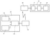
- the partial cross section figure of the indicating instrument of 1st Embodiment of this invention The block diagram which shows the structure of the indicating instrument of the embodiment.
- the wave form diagram which shows the output of each signal of the embodiment.
- the indicating instrument 1 is mounted on a stepping motor 20 that is a driving device disposed behind the dial 10 that is a display member, and a rotating shaft 21 of the stepping motor 20, and is around the rotating shaft 21.
- An indicator member 30 having a base portion 31 and an indicator portion 32, a light source 40 disposed on the indicator member 30 to cause the indicator portion 32 to emit light, a primary coil 50 provided on the stepping motor 20 side,
- the secondary coil 60 capable of electromagnetic induction with the secondary coil 50 and provided on the indicator member 30 side, and the indicator member 30 side which is a wiring member provided on the indicator member 30 and electrically connecting the secondary coil 60 and the light source 40
- a control unit 82 for outputting a control signal
- a luminance adjusting unit 83 for outputting the drive signal a signal obtained by superimposing
- the dial plate 10 is made of synthetic resin and has an indicator portion made of characters (not shown).
- the stepping motor 20 is a movement that rotates the indicating member 30.
- the rotation shaft 21 is rotatably provided to the stepping motor 20 and rotates.
- the indication member 30 is press-fitted and held at the tip of the rotation shaft 21. Note that the rotation is a circular movement in both forward and reverse directions with the rotation shaft 21 as a central axis.
- the indicating member 30 includes a base portion 31 and an indicating portion 32, and indicates the indicator portion of the dial 10 by the operation of the rotating shaft 21.
- the base 31 is made of synthetic resin and is press-fitted and held on the rotating shaft 21.
- the base 31 holds the secondary coil 60, the wiring member 70, the instruction unit 32, and the like.
- the instruction unit 32 is made of a permeable resin, and indicates the indicator portion of the dial 10.
- the instruction unit 32 receives light emitted from the light source 40 and emits light.
- the light source 40 is provided in the wiring member 70 and is made of, for example, a light emitting diode, and supplies light to the instruction unit 32.
- the primary coil 50 is held by a coil base 52 and is electrically connected to a circuit board 80 provided on the stepping motor side.
- the primary coil 50 generates a predetermined magnetic field by a signal from the brightness adjusting unit 83 and supplies electric power by the secondary coil 60 and electromagnetic induction.
- the primary yoke 51 is held by the coil pedestal 52 and is made of a soft magnetic material having a high magnetic permeability, such as iron, ferrite, permalloy, etc., and efficiently transmits a magnetic field generated from the primary coil 50 to the secondary coil 60. It is. Or it has a role of a magnetic shield which prevents the magnetic field leakage to the opposite side to the secondary coil 60.
- the coil base 52 is held on the circuit board 80 and holds the primary coil 50 and the primary yoke 51.
- the secondary coil 60 is held by the wiring member 70 and converts the magnetic field generated by the primary coil 50 into electric energy by electromagnetic induction.
- the secondary yoke 61 is held by the wiring member 70 and is made of a soft magnetic material having a high magnetic permeability like the primary yoke 51, for example, iron, ferrite, permalloy, etc., and generates a magnetic field generated from the primary coil 50. It is efficiently transmitted to the secondary coil 60. Or it has a role of the magnetic shield which prevents the magnetic field leakage to the opposite side to the primary coil 50.
- the wiring member 70 includes a conductor (not shown) and electrically connects the secondary coil 60, the light source 40, the resonant circuit element 71, and the rectifier circuit element 72, and electrical energy obtained by the electromagnetic induction action of the secondary coil 60. Is supplied to the light source 40.
- the resonance circuit element 71 is mainly composed of a capacitor and causes an electrical resonance phenomenon with the secondary coil 60.
- the rectifier circuit element 72 is mainly composed of a diode, and converts AC electrical energy obtained by the secondary coil 60 into DC. Depending on the system, a plurality of diodes may be required.
- the circuit board 80 supplies power to the stepping motor 20, the primary coil 50, and the like, and includes a driving unit 81, a control unit 82, and a luminance adjusting unit 83.
- the driving means 81 is mainly an oscillation circuit, and generates and outputs a driving signal 811 for supplying power obtained from a power source such as a battery (not shown) to the primary coil 50.
- the driving signal 811 is the primary coil. It encourages the generation of 50 alternating magnetic fields.
- the drive signal 811 is an input signal for generating an alternating magnetic field of the primary coil 50, and is a rectangular wave signal having a specific frequency as shown in FIG. In the present embodiment, the frequency of the rectangular wave signal is 250 kHz.
- the horizontal axis represents time, and the vertical axis represents voltage output. The same applies to a graph representing a control signal 821 and a superimposed signal 831 described later. Further, FIG. 3 is partially emphasized in order to facilitate understanding of the present invention.
- the drive signal 811 may be a sine wave.
- the control means 82 includes, for example, a CPU and outputs a control signal 821 for dimming the light source 40.
- the control signal 821 is a PWM signal, and its frequency is 250 Hz.
- the control means 82 also outputs a rotation axis drive signal for driving the rotation axis 21 of the stepping motor 20.
- the luminance adjusting unit 83 outputs a signal 831 obtained by superimposing (mixing) the drive signal 811 and the control signal 821 to the primary coil 50. As shown in FIG. 3, for example, when the luminance is suppressed to 40%, the luminance adjusting unit 83 thins the drive signal 811 by the control signal 821 and apparently reduces the input signal to the primary coil 50. Thus, the light control of the light source 40 is performed.
- the cover 90 is made of a synthetic resin and covers the light source 40, the secondary coil 60, and the like.
- the indicating instrument 1 that simplifies the configuration and can reduce the cost is provided in the indicating instrument 1 that supplies electric power to the light source 40 of the indicating member 30 using electromagnetic induction. be able to.
- the present invention can be used for an indicating instrument having a pointer.
- Indicator 10 Dial (Display material) 20 Stepping motor (drive device) 21 rotating shaft 30 indicating member 32 indicating unit 40 light source 50 primary coil 60 secondary coil 80 circuit board 81 driving means 82 control means 83 luminance adjusting means 811 driving signal 821 control signal
Landscapes
- Engineering & Computer Science (AREA)
- Physics & Mathematics (AREA)
- General Physics & Mathematics (AREA)
- Chemical & Material Sciences (AREA)
- Combustion & Propulsion (AREA)
- Transportation (AREA)
- Mechanical Engineering (AREA)
- Details Of Measuring Devices (AREA)
- Instrument Panels (AREA)
Abstract
電磁誘導作用を用いた指示計器において構成を簡素化し、かつコストを抑えることが可能な指示計器を提供する。 表示部材10の背後側に配置される駆動装置20と、指示部32を有し駆動装置20の回動軸21に装着される指示部材30と、指示部32を発光させ指示部材30に配設される光源40と、駆動装置20側に設けられる1次コイル50と、1次コイル50と電磁誘導が可能で指示部材30側に設けられる2次コイル60と、を備えた指示計器1において、1次コイル50に電力を供給する駆動信号811を出力する駆動手段81と、光源40の調光用の制御信号821を出力する制御手段82と、駆動信号811と調光用の制御信号821を重畳した信号831を1次コイル50に出力する輝度調整手段83とを備えたものである。
Description
本発明は、指針を備えた指示計器に関するものである。
従来の指示計器は、例えば、特許文献1に開示されるものがある。この指示計器は、文字板の背後側に配置される駆動装置であるステッピングモータと、このステッピングモータの回動軸に装着され、基部と指示部とを有する指針本体と、前記指示部を発光させる光源と、ステッピングモータ側に設けられる1次コイルと、この1次コイルから電磁誘導によって電力が供給されるとともに前記指針本体に設けられた2次コイルとを備えたものである。
前記光源を発光させる場合には、矩形波もしくは交流波を駆動信号として発する駆動回路を設け、この駆動信号の波高値もしくは周波数を可変する専用の制御回路を用いて、前記1次コイルを駆動し、前記光源を調光制御するものであった。
しかしながら、専用の制御回路を必要とすることから構成が複雑化し、コストが嵩むといった問題点があった。
そこで本発明は、前述の問題点に着目し、電磁誘導作用を用いて指針に電力を供給する指示計器において、構成を簡素化し、かつコストを抑えることが可能な指示計器を提供することを目的とするものである。
本発明における指示計器は、表示部材の背後側に配置される駆動装置と、指示部を有し前記駆動装置の回動軸に装着される指示部材と、前記指示部を発光させ前記指示部材に配設される光源と、前記駆動装置側に設けられる1次コイルと、前記1次コイルと電磁誘導が可能で前記指示部材側に設けられる2次コイルと、を備えた指示計器において、前記1次コイルに電力を供給する駆動信号を出力する駆動手段と、前記光源の調光用の制御信号を出力する制御手段と、前記駆動信号と前記調光用の制御信号を重畳した信号を前記1次コイルに出力する輝度調整手段とを備えたものである。
また、前記制御手段は、前記駆動装置の前記回動軸を駆動するものである。
以上のように本発明によれば、電磁誘導作用を用いて指針に電力を供給する指示計器において、構成を簡素化し、かつコストを抑えることが可能な指示計器を提供することができる。
以下、添付図面に基づいて、本発明の第1実施形態を説明する。
本実施形態の指示計器1は、表示部材である文字板10の背後側に配置される駆動装置であるステッピングモータ20と、ステッピングモータ20の回動軸21に装着され、回動軸21の周囲に位置する基部31と指示部32とを有する指示部材30と、指示部32を発光させるべく指示部材30に配設される光源40と、ステッピングモータ20側に設けられる1次コイル50と、1次コイル50と電磁誘導が可能で、指示部材30側に設けられる2次コイル60と、指示部材30に設けられ2次コイル60と光源40を電気的に接続する配線部材である指示部材30側回路基板70と、電磁誘導作用によって2次コイル60に電力を発生させる為に1次コイル50に電力を供給する駆動信号を出力する駆動手段81と、光源40の調光用の制御信号を出力する制御手段82と、前記駆動信号と前記調光用の制御信号を重畳した信号を1次コイル50に出力する輝度調整手段83と、を備えている。
文字板10は、合成樹脂からなり、図示しない文字などからなる指標部を備えている。
ステッピングモータ20は、指示部材30を回動させるムーブメントである。回動軸21は、ステッピングモータ20に回動可能に備えられ、回動するものである。回動軸21の先端には、指示部材30が圧入保持される。なお、回動とは、回動軸21を中心軸として、正逆両方向に円運動することである。
指示部材30は、基部31と指示部32からなり、回動軸21の動作によって、文字板10の前記指標部を指示するものである。
基部31は、合成樹脂からなり、回動軸21に圧入保持されるものである。また、基部31は、2次コイル60、配線部材70、指示部32などを保持するものである。
指示部32は、透過性樹脂からなり、文字板10の前記指標部を指示するものである。指示部32は、光源40から発せられる光を受けて発光するものである。
光源40は、配線部材70に備え付けられ、例えば、発光ダイオードからなり、指示部32に光を供給するものである。
1次コイル50は、コイル台座52に保持され、ステッピングモータ側に設けた回路基板80と電気的に接続されている。1次コイル50は、輝度調整手段83からの信号によって、所定の磁界を発生し、2次コイル60と電磁誘導作用によって、電力を供給するものである。
1次ヨーク51は、コイル台座52に保持され、高い透磁率を持つ軟磁性材料、例えば鉄、フェライト、パーマロイなどからなり、1次コイル50から発せられる磁界を2次コイル60に効率良く伝えるものである。または、2次コイル60とは反対側への磁界漏れを防ぐ磁気シールドの役割をもつものである。
コイル台座52は、回路基板80に保持され、1次コイル50と1次ヨーク51を保持するものである。
2次コイル60は、配線部材70に保持され、1次コイル50で発せられる磁界を電磁誘導作用によって電気エネルギーに変換するものである。
2次ヨーク61は、配線部材70に保持され、1次ヨーク51と同様に高い透磁率を持つ軟磁性材料、例えば、鉄、フェライト、パーマロイなどからなり、1次コイル50から発せられる磁界を、2次コイル60に効率良く伝えるものである。または、1次コイル50とは反対側への磁界漏れを防ぐ磁気シールドの役割をもつものである。
配線部材70は、図示しない導体を備え、2次コイル60、光源40、共振回路素子71、整流回路素子72を電気的接続しており、2次コイル60の電磁誘導作用によって得られた電気エネルギーを光源40に供給するものである。
共振回路素子71は、主にコンデンサからなり、2次コイル60と電気的に共振現象を起こすものである。
整流回路素子72は、主にダイオードからなり、2次コイル60で得られる交流の電気エネルギーを直流に変換するものである。方式によっては複数個のダイオードを要することもある。
回路基板80は、ステッピングモータ20や1次コイル50などに電力を供給するものであり、駆動手段81、制御手段82及び輝度調整手段83を有するものである。
駆動手段81は、主に発振回路であり、図示しないバッテリなどの電源から得た電力を1次コイル50へ供給する駆動信号811を生成し出力するものであり、駆動信号811は、1次コイル50の交番磁界の発生を促すものである。
駆動信号811は、1次コイル50の交番磁界発生に対する入力信号で、図3で示すように、特定の周波数の矩形波信号である。本実施形態では、矩形波信号の周波数は、250kHzである。なお、図3の横軸は時間であり、縦軸は電圧の出力を示すものであり、後述する制御信号821、重畳した信号831を表すグラフも同様である。また、図3は、本発明の理解を容易にするために、一部を強調してある。なお、駆動信号811は、正弦波であってもよい。
制御手段82は、例えば、CPUなどからなり、光源40の調光用の制御信号821を出力するものである。制御信号821は、PWM信号であり、その周波数は、250Hzである。
なお、制御手段82は、ステッピングモータ20の回動軸21を駆動する回動軸駆動信号を出力するものでもある。
輝度調整手段83は、駆動信号811および制御信号821を重畳(ミキシング)した信号831を1次コイル50へ出力するものである。図3で示すように、例えば、輝度を40%に抑える場合は、輝度調整手段83は、制御信号821により、駆動信号811を間引き、見かけ上、1次コイル50への入力信号を低減することによって光源40の調光制御を行うものである。
カバー90は、合成樹脂からなり光源40、2次コイル60などを覆うものである。
以上のように構成したことによって、電磁誘導作用を用いて指示部材30の光源40に電力を供給する指示計器1において、構成を簡素化し、かつコストを抑えることが可能な指示計器1を提供することができる。
本発明は、指針を備えた指示計器に利用することができる。
1 指示計器
10 文字板(表示部材)
20 ステッピングモータ(駆動装置)
21 回動軸
30 指示部材
32 指示部
40 光源
50 1次コイル
60 2次コイル
80 回路基板
81 駆動手段
82 制御手段
83 輝度調整手段
811 駆動信号
821 制御信号
10 文字板(表示部材)
20 ステッピングモータ(駆動装置)
21 回動軸
30 指示部材
32 指示部
40 光源
50 1次コイル
60 2次コイル
80 回路基板
81 駆動手段
82 制御手段
83 輝度調整手段
811 駆動信号
821 制御信号
Claims (2)
- 表示部材の背後側に配置される駆動装置と、指示部を有し前記駆動装置の回動軸に装着される指示部材と、前記指示部を発光させ前記指示部材に配設される光源と、前記駆動装置側に設けられる1次コイルと、前記1次コイルと電磁誘導が可能で前記指示部材側に設けられる2次コイルと、を備えた指示計器において、前記1次コイルに電力を供給する駆動信号を出力する駆動手段と、前記光源の調光用の制御信号を出力する制御手段と、前記駆動信号と前記調光用の制御信号を重畳した信号を前記1次コイルに出力する輝度調整手段とを備えたことを特徴とする指示計器。
- 前記制御手段は、前記駆動装置の前記回動軸を駆動することを特徴とする請求項1に記載の指示計器。
Applications Claiming Priority (2)
| Application Number | Priority Date | Filing Date | Title |
|---|---|---|---|
| JP2011-146011 | 2011-06-30 | ||
| JP2011146011A JP2013011572A (ja) | 2011-06-30 | 2011-06-30 | 指示計器 |
Publications (1)
| Publication Number | Publication Date |
|---|---|
| WO2013002011A1 true WO2013002011A1 (ja) | 2013-01-03 |
Family
ID=47423911
Family Applications (1)
| Application Number | Title | Priority Date | Filing Date |
|---|---|---|---|
| PCT/JP2012/064755 Ceased WO2013002011A1 (ja) | 2011-06-30 | 2012-06-08 | 指示計器 |
Country Status (2)
| Country | Link |
|---|---|
| JP (1) | JP2013011572A (ja) |
| WO (1) | WO2013002011A1 (ja) |
Citations (4)
| Publication number | Priority date | Publication date | Assignee | Title |
|---|---|---|---|---|
| JPH0415016U (ja) * | 1990-05-25 | 1992-02-06 | ||
| JPH06300590A (ja) * | 1993-04-15 | 1994-10-28 | Nippondenso Co Ltd | 指針照明計器 |
| JP2005061920A (ja) * | 2003-08-08 | 2005-03-10 | Yazaki Corp | 自発光指針駆動装置 |
| JP2011064668A (ja) * | 2009-08-21 | 2011-03-31 | Nippon Seiki Co Ltd | 指示計器 |
-
2011
- 2011-06-30 JP JP2011146011A patent/JP2013011572A/ja not_active Withdrawn
-
2012
- 2012-06-08 WO PCT/JP2012/064755 patent/WO2013002011A1/ja not_active Ceased
Patent Citations (4)
| Publication number | Priority date | Publication date | Assignee | Title |
|---|---|---|---|---|
| JPH0415016U (ja) * | 1990-05-25 | 1992-02-06 | ||
| JPH06300590A (ja) * | 1993-04-15 | 1994-10-28 | Nippondenso Co Ltd | 指針照明計器 |
| JP2005061920A (ja) * | 2003-08-08 | 2005-03-10 | Yazaki Corp | 自発光指針駆動装置 |
| JP2011064668A (ja) * | 2009-08-21 | 2011-03-31 | Nippon Seiki Co Ltd | 指示計器 |
Also Published As
| Publication number | Publication date |
|---|---|
| JP2013011572A (ja) | 2013-01-17 |
Similar Documents
| Publication | Publication Date | Title |
|---|---|---|
| JP2011010444A (ja) | 非接触充電器 | |
| EP2869316A1 (en) | Rotating transformers for electrical machines | |
| JP2006238548A (ja) | 無線電力供給装置 | |
| US20120081040A1 (en) | Light emitting diode driving circuit | |
| WO2021036886A1 (zh) | 一种轮毂充电装置、显示装置及显示控制电路 | |
| JP2011160507A (ja) | 発光部付き振動発電機 | |
| KR940004395B1 (ko) | 발광침의 전력공급장치 | |
| JP2013011572A (ja) | 指示計器 | |
| WO2008071198A1 (en) | Bicycle generator | |
| CA2377917A1 (en) | Windmill with illuminated blades and generation of electrical energy | |
| JP3178406U (ja) | 水中用照明装置 | |
| US9068865B2 (en) | Meter with pointer | |
| CN110062492B (zh) | 具有降低的可听噪声的pwm调光 | |
| KR20120089113A (ko) | 유도 전류를 이용한 발광 장치 | |
| JPH06300590A (ja) | 指針照明計器 | |
| CN101311545A (zh) | 具显示器功能的风扇 | |
| CN202549272U (zh) | 高稳定性有源电磁蜂鸣器 | |
| JP2007129462A (ja) | 非接触型データ及び電力伝送装置 | |
| JP2005072366A (ja) | 給電装置 | |
| JP2012178958A (ja) | アンテナ | |
| JP2006210000A (ja) | 電飾装置 | |
| WO2014031627A1 (en) | Wireless led lighting | |
| KR101598416B1 (ko) | 공심 코어를 갖는 공진 코일의 스트리머 제어 장치 | |
| JP2019126259A (ja) | 給電装置及びプログラム | |
| RU2013117098A (ru) | Генератор для питания стоматологической полимеризационной лампы |
Legal Events
| Date | Code | Title | Description |
|---|---|---|---|
| 121 | Ep: the epo has been informed by wipo that ep was designated in this application |
Ref document number: 12804278 Country of ref document: EP Kind code of ref document: A1 |
|
| NENP | Non-entry into the national phase |
Ref country code: DE |
|
| 122 | Ep: pct application non-entry in european phase |
Ref document number: 12804278 Country of ref document: EP Kind code of ref document: A1 |