WO2012176805A1 - Built-in type air conditioning device - Google Patents
Built-in type air conditioning device Download PDFInfo
- Publication number
- WO2012176805A1 WO2012176805A1 PCT/JP2012/065747 JP2012065747W WO2012176805A1 WO 2012176805 A1 WO2012176805 A1 WO 2012176805A1 JP 2012065747 W JP2012065747 W JP 2012065747W WO 2012176805 A1 WO2012176805 A1 WO 2012176805A1
- Authority
- WO
- WIPO (PCT)
- Prior art keywords
- heat exchanger
- heat exchange
- unit
- blower
- built
- Prior art date
Links
Images


Classifications
-
- F—MECHANICAL ENGINEERING; LIGHTING; HEATING; WEAPONS; BLASTING
- F24—HEATING; RANGES; VENTILATING
- F24F—AIR-CONDITIONING; AIR-HUMIDIFICATION; VENTILATION; USE OF AIR CURRENTS FOR SCREENING
- F24F1/00—Room units for air-conditioning, e.g. separate or self-contained units or units receiving primary air from a central station
- F24F1/0007—Indoor units, e.g. fan coil units
- F24F1/0059—Indoor units, e.g. fan coil units characterised by heat exchangers
- F24F1/0063—Indoor units, e.g. fan coil units characterised by heat exchangers by the mounting or arrangement of the heat exchangers
-
- F—MECHANICAL ENGINEERING; LIGHTING; HEATING; WEAPONS; BLASTING
- F24—HEATING; RANGES; VENTILATING
- F24F—AIR-CONDITIONING; AIR-HUMIDIFICATION; VENTILATION; USE OF AIR CURRENTS FOR SCREENING
- F24F13/00—Details common to, or for air-conditioning, air-humidification, ventilation or use of air currents for screening
- F24F13/22—Means for preventing condensation or evacuating condensate
-
- F—MECHANICAL ENGINEERING; LIGHTING; HEATING; WEAPONS; BLASTING
- F24—HEATING; RANGES; VENTILATING
- F24F—AIR-CONDITIONING; AIR-HUMIDIFICATION; VENTILATION; USE OF AIR CURRENTS FOR SCREENING
- F24F1/00—Room units for air-conditioning, e.g. separate or self-contained units or units receiving primary air from a central station
- F24F1/0007—Indoor units, e.g. fan coil units
- F24F1/0043—Indoor units, e.g. fan coil units characterised by mounting arrangements
- F24F1/0047—Indoor units, e.g. fan coil units characterised by mounting arrangements mounted in the ceiling or at the ceiling
-
- F—MECHANICAL ENGINEERING; LIGHTING; HEATING; WEAPONS; BLASTING
- F24—HEATING; RANGES; VENTILATING
- F24F—AIR-CONDITIONING; AIR-HUMIDIFICATION; VENTILATION; USE OF AIR CURRENTS FOR SCREENING
- F24F13/00—Details common to, or for air-conditioning, air-humidification, ventilation or use of air currents for screening
- F24F13/30—Arrangement or mounting of heat-exchangers
-
- F—MECHANICAL ENGINEERING; LIGHTING; HEATING; WEAPONS; BLASTING
- F28—HEAT EXCHANGE IN GENERAL
- F28D—HEAT-EXCHANGE APPARATUS, NOT PROVIDED FOR IN ANOTHER SUBCLASS, IN WHICH THE HEAT-EXCHANGE MEDIA DO NOT COME INTO DIRECT CONTACT
- F28D1/00—Heat-exchange apparatus having stationary conduit assemblies for one heat-exchange medium only, the media being in contact with different sides of the conduit wall, in which the other heat-exchange medium is a large body of fluid, e.g. domestic or motor car radiators
- F28D1/02—Heat-exchange apparatus having stationary conduit assemblies for one heat-exchange medium only, the media being in contact with different sides of the conduit wall, in which the other heat-exchange medium is a large body of fluid, e.g. domestic or motor car radiators with heat-exchange conduits immersed in the body of fluid
- F28D1/04—Heat-exchange apparatus having stationary conduit assemblies for one heat-exchange medium only, the media being in contact with different sides of the conduit wall, in which the other heat-exchange medium is a large body of fluid, e.g. domestic or motor car radiators with heat-exchange conduits immersed in the body of fluid with tubular conduits
- F28D1/0408—Multi-circuit heat exchangers, e.g. integrating different heat exchange sections in the same unit or heat exchangers for more than two fluids
-
- F—MECHANICAL ENGINEERING; LIGHTING; HEATING; WEAPONS; BLASTING
- F28—HEAT EXCHANGE IN GENERAL
- F28D—HEAT-EXCHANGE APPARATUS, NOT PROVIDED FOR IN ANOTHER SUBCLASS, IN WHICH THE HEAT-EXCHANGE MEDIA DO NOT COME INTO DIRECT CONTACT
- F28D1/00—Heat-exchange apparatus having stationary conduit assemblies for one heat-exchange medium only, the media being in contact with different sides of the conduit wall, in which the other heat-exchange medium is a large body of fluid, e.g. domestic or motor car radiators
- F28D1/02—Heat-exchange apparatus having stationary conduit assemblies for one heat-exchange medium only, the media being in contact with different sides of the conduit wall, in which the other heat-exchange medium is a large body of fluid, e.g. domestic or motor car radiators with heat-exchange conduits immersed in the body of fluid
- F28D2001/0253—Particular components
- F28D2001/026—Cores
- F28D2001/0266—Particular core assemblies, e.g. having different orientations or having different geometric features
-
- F—MECHANICAL ENGINEERING; LIGHTING; HEATING; WEAPONS; BLASTING
- F28—HEAT EXCHANGE IN GENERAL
- F28D—HEAT-EXCHANGE APPARATUS, NOT PROVIDED FOR IN ANOTHER SUBCLASS, IN WHICH THE HEAT-EXCHANGE MEDIA DO NOT COME INTO DIRECT CONTACT
- F28D21/00—Heat-exchange apparatus not covered by any of the groups F28D1/00 - F28D20/00
- F28D2021/0019—Other heat exchangers for particular applications; Heat exchange systems not otherwise provided for
- F28D2021/0068—Other heat exchangers for particular applications; Heat exchange systems not otherwise provided for for refrigerant cycles
Definitions
- the present invention relates to a built-in type air conditioner including an indoor unit installed on a ceiling of a building.
- a built-in type air conditioner including an indoor unit installed in a ceiling part such as a ceiling space of a building and an outdoor unit connected to the indoor unit via a refrigerant pipe is known.
- a compressor and an outdoor heat exchanger are accommodated in the outdoor unit, and an indoor heat exchanger and a blower are accommodated in the indoor unit.
- the compressor, the outdoor heat exchanger, and the indoor heat exchanger are connected by a refrigerant pipe to form a refrigerant circuit.
- coolant which flows through the inside of an indoor heat exchanger is blown out to the to-be-conditioned room via the blowing duct (for example, refer patent document 1).
- the indoor unit of a built-in type air conditioner is installed in a ceiling portion where installation space is limited.
- the two flat plate-like indoor heat exchangers (the upper heat exchanging portion and the lower heat exchanging portion) are viewed from the side. Some of them are connected so as to form a square shape.
- the upper heat exchanger is disposed at a position away from the drain pan. Therefore, there is a case where drain water from the upper heat exchanging part scatters from the U-shaped connecting part and blows out from the outlet by the air blown from the blower.
- the position or distance of the blower with respect to each part in the heat exchange surface becomes uneven. Therefore, there is a problem that differences in wind speed or temperature unevenness occur in each part in the heat exchange surface, and the heat exchange efficiency of the indoor heat exchanger cannot be made uniform.
- the fixing structure tends to be complicated.
- the fixture jumps out into the air passage of the indoor unit and becomes resistance to ventilation, or the secondary side chamber on the downstream side of the heat exchanger is separated from the primary side chamber on the upstream side and insulated.
- the number of parts increased, and the installation workability became worse.
- such a built-in type air conditioner is installed in the ceiling, once installed, it is difficult to remove the air conditioner for maintenance.
- a refrigerant pipe connected to the indoor heat exchanger or a drain pipe connected to a drain pump for draining drain water generated by the indoor heat exchanger and received by a drain pan is provided, for example, as a unit.
- the side plate of the case is passed through and pulled out from the unit body. For this reason, when removing the indoor heat exchanger from the unit main body during maintenance of the indoor heat exchanger, etc., these refrigerant pipes and drain pipes are connected to the inside of the unit main body from the indoor heat exchanger or drain pump in a narrow ceiling space. It was necessary to perform the work of removing the indoor heat exchanger from the unit body after removing or removing the unit body from the ceiling space together with the refrigerant piping, and the workability was poor.
- the present invention provides a built-in type air conditioner that solves the problems of the above-described conventional technology and can prevent the drain water from scattering from the heat exchanger while increasing the capacity of the indoor heat exchanger.
- the purpose is to do.
- Another object of the present invention is to provide a built-in type air conditioner that can make the heat exchange efficiency uniform while increasing the capacity of the indoor heat exchanger.
- It is another object of the present invention to provide a built-in type air conditioner that can solve the above-described problems of the prior art and can be mounted with an indoor heat exchanger with a simple structure and a small number of parts.
- Another object of the present invention is to provide a built-in type air conditioner that solves the problems of the conventional techniques described above and improves the maintainability of the indoor heat exchanger.
- the present invention comprises a unit main body configured to accommodate a heat exchanger and a blower, and the upper heat exchanging unit connected to the substantially square shape in a side view, and It includes a lower heat exchanging part, and is provided with a blower outlet of the blower so as to face the apex of the character, and in the unit body, the lower heat exchanging part and the upper heat exchanging part have the same width as the unit width. It is accommodated substantially fully, and the lower end of the upper heat exchanging portion is disposed on the lower heat exchanging portion at the apex of the substantially square shape.
- the upper heat exchanging portion is disposed closer to the blower than the upper end of the lower heat exchanging portion, the air outflow side surface of the upper heat exchanging portion, and the lower heat exchanging portion A step is provided between the upper end and the upper end.
- the present invention includes a unit main body configured to accommodate a heat exchanger and a blower, and the heat exchanger is connected to a substantially square shape in a side view. And a lower heat exchanging part, and the blower outlet of the blower is provided facing the apex of the character, and the lower heat exchanging part and the upper heat exchanging part have the same width in the unit body.
- the unit is accommodated in a substantially full width, and the heat exchange area of the lower heat exchange part is set larger than that of the upper heat exchange part.
- the present invention is characterized in that the heat exchange area of the upper heat exchange part is set to approximately 60% of the heat exchange area of the lower heat exchange part.
- the present invention divides the inside of the unit body into a blower chamber in which the blower is accommodated and a heat exchange chamber in which the heat exchanger is accommodated, and a drain pan that covers the entire bottom of the heat exchange chamber is provided, The lower end of the lower heat exchange part is placed on the drain pan.
- the inside of the unit body is partitioned by a partition plate into a heat exchange chamber that houses a heat exchanger and a blower chamber that houses a blower, and is sucked by the blower.
- the heat exchanger is fixed to the front plate and the top plate of the unit body at both ends of the heat exchanger, A resin-made fixing member for fixing inside the main body is provided.
- a vent hole through which the U-shaped tube of the heat exchanger passes is provided in a fixing member on one end side of both ends of the heat exchanger,
- the fixing member is provided with a U-shaped groove formed along the shape of the heat exchanger, and the refrigerant pipe of the heat exchanger is penetrated from the groove.
- the inside of the unit body is partitioned by a partition plate into a heat exchange chamber that houses a heat exchanger and a blower chamber that houses a blower, and is sucked by the blower.
- the heat exchanger is formed to be detachable from the opening on the lower surface of the unit body into the heat exchange chamber, and the unit body
- the refrigerant pipe of the heat exchanger protruding outward from the side plate is an inverted U-shaped groove that opens downward so that it can be inserted into the heat exchange chamber from the opening side integrally with the heat exchanger.
- a lid body having a U-shaped groove is attached to the side plate, and the refrigerant pipe can be held on the side plate by cooperation of the U-shaped groove of the lid body and the inverted U-shaped groove of the side plate. It is characterized by that.
- the present invention provides the above-described built-in type air conditioner, wherein the unit main body includes a drain pan that receives drain water generated by the heat exchanger, and drain water accumulated in the drain pan through the drain pipe.
- a drain pump for draining outside the unit main body is built in, and a pump unit in which the drain pump and the drain pipe are integrally combined is detachably disposed on the side plate of the unit main body on the side surface of the unit main body. It is characterized by being.
- the present invention is provided at both ends of the heat exchanger, is inserted into the heat exchange chamber from the opening side integrally with the heat exchanger, and is fixed to the front plate and the top plate of the unit body.
- the heat exchanger includes a resin fixing member that fixes the heat exchanger to the inside of the unit main body.
- the present invention provides the above built-in type air conditioner, wherein the heat exchanger includes an upper heat exchanging portion and a lower heat exchanging portion that are connected to each other in a side view in a side view, A blower outlet of the blower is provided so as to face each other.
- the present invention is characterized in that, in the built-in type air conditioner described above, the open side of the heat exchanger is opposed to the blower outlet of the blower.
- the present invention is characterized in that, in the built-in type air conditioner described above, the open side of the cross-section of the heat exchanger is directed to the downstream side of the heat exchanger.
- the built-in air conditioner in the built-in air conditioner described above, the built-in air conditioner according to any one of claims 1 to 8, wherein the blower is a centrifugal blower.
- resin fixing members for fixing the heat exchanger to the inside of the unit main body are provided at both ends of the heat exchanger and fixed to the front plate and the top plate of the unit main body.
- a heat exchanger is detachably formed in the heat exchange chamber from the opening on the lower surface of the unit main body, and the side plate of the unit main body protrudes outward from the side plate.
- the refrigerant pipe of the exchanger is provided with an inverted U-shaped groove that opens downward so that the refrigerant pipe can be inserted into the heat exchange chamber from the opening side integrally with the heat exchanger, and the lid having the U-shaped groove is disposed on the side plate. And the refrigerant pipe can be held on the side plate by the cooperation of the U-shaped groove of the lid and the inverted U-shaped groove of the side plate.
- tube can be hold
- the lid is removed from the side plate so that the heat exchanger and the refrigerant tube can be easily removed from the opening on the lower surface of the unit body without removing the refrigerant tube from the heat exchanger. Can be made. Therefore, the maintainability of the indoor heat exchanger can be improved.
- a pump unit in which a drain pump and a drain pipe are integrally combined is detachably disposed in the vicinity of the lid on the side surface of the unit main body.
- (A) is a front view of the other side fixing member
- (B) is a front view which shows the state which attached the other side fixing member to the indoor heat exchanger.
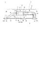
- a built-in type air conditioner 1 includes an outdoor unit (not shown) and an indoor unit 5 connected to the outdoor unit through a refrigerant pipe.
- the outdoor unit is installed outdoors such as on the rooftop of a building, exchanges heat with outdoor air, condenses the refrigerant during cooling operation and releases heat to the outside, and evaporates the refrigerant during heating operation. The heat is taken from outside air.
- the built-in type air conditioning apparatus 1 circulates this refrigerant between the outdoor unit and the indoor heat exchanger (heat exchanger) 60 of the indoor unit 5 to perform air conditioning of the conditioned room 2.
- the indoor unit 5 is disposed in a state of being hung in a ceiling space 34 between the ceiling 32 and the ceiling plate 33 of the building 31.
- the indoor unit 5 includes an indoor heat exchanger (heat exchanger) 60 and a blower 50 that blows air to the indoor heat exchanger 60.
- the indoor unit 5 includes a suction duct 53 and a blowout duct 54 that extend from the unit body 10 to the ceiling plate 33.
- the unit case 11 of the unit body 10 is formed in a substantially rectangular shape and includes a top plate 12, a bottom plate 13, side plates 14A and 14B, a suction side panel 15, and a blowout side panel (front plate) 16.
- a plurality of suspension fittings 41 are fixed to the side plates 14 ⁇ / b> A and 14 ⁇ / b> B of the unit case 11.
- Four suspension bolts 42 are suspended from the ceiling 32.
- the unit main body 10 is provided in a state in which the hanging metal fittings 41 are respectively fixed to the suspension bolts 42 and are hung in the ceiling back space 34.
- a detachable ceiling panel 35 is attached to the ceiling plate 33 at an appropriate position, particularly near the unit main body 10.
- Various maintenance of the indoor unit 5 can be performed from the conditioned room 2 side by removing the ceiling panel 35.
- the suction side panel 15 and the blowout side panel 16 are respectively disposed on a pair of opposing side surfaces of the unit case 11.
- the suction side panel 15 is arrange
- the blowout side panel 16 is arrange
- an air inlet 51 and an air inlet 52 are provided for communicating the interior of the conditioned room 2 with the ceiling space 34.
- the suction port 17 of the unit case 11 and the suction port 51 of the ceiling plate 33 are connected by a suction duct 53. Further, the air outlet 18 of the unit case 11 and the air supply port 52 of the ceiling plate 33 are connected by an air outlet duct 54.
- the indoor unit 5 sucks the air in the conditioned room 2 into the unit body 10 through the air inlet 51, the air inlet duct 53, and the air inlet 17 by driving the blower 50, and the air thus sucked into the indoor heat exchanger 60. Air is blown to exchange heat with the refrigerant flowing in the indoor heat exchanger 60.
- the conditioned air that has exchanged heat with the refrigerant flowing in the indoor heat exchanger 60 is supplied into the conditioned room 2 through the air outlet 18, the air outlet duct 54, and the air inlet 52. That is, the indoor unit 5 sucks the air in the conditioned room 2, exchanges heat with the refrigerant flowing in the indoor heat exchanger 60, and blows the conditioned air heat-exchanged with the refrigerant to the conditioned room 2 again.
- One side surface of the unit case 11 is formed by a side plate 14A as shown in FIG.
- a maintenance panel 56, a pump unit 75, and a lid (pipe presser) 68 are detachably attached to the side plate 14A.
- the side plate 14A is provided with a maintenance opening (not shown) for performing maintenance of the electrical unit, and a maintenance panel 56 is attached to the side plate 14A so as to close the maintenance opening.
- the pump unit 75 includes a drain pump 78 that draws drain water from a drain pan 70 to be described later, and a fixture 79 for the drain pump 78.
- the side plate 14A is provided with a pump mounting opening 75A, and the drain pump 78 is accommodated in the unit case 11 through the pump mounting opening 75A.
- the fixture 79 fixes the drain pump 78 and is attached to the side plate 14A so as to close the pump attachment opening 75A.
- the side plate 14A is provided with a notch 68C through which the auxiliary refrigerant pipe (refrigerant pipe) 67 passes.
- the lid body 68 is configured to hold the auxiliary refrigerant pipe 67 penetrating the side plate 14A through the notch 68C and close the notch 68C.
- a drain pipe cutout 19 is provided by cutting out the side plate 14A so as to open downward.
- the drain pipe notch 19 is provided with a drain pipe presser 76 that is detachably fitted to the drain pipe notch 19.
- the drain pipe presser 76 is provided with a hole 76A (see FIG. 10) through which the drain drain pipe 77 passes.
- a drain drain pipe 77 connected to the drain pan 70 is provided so as to protrude from the hole 76A. For example, when drain water remaining in the drain pan 70 is discharged during maintenance of the unit body 10, the drain water can be discharged to the outside of the unit body 10 through the drain drain pipe 77.
- Screw holes 69 ⁇ / b> A and 69 ⁇ / b> A are formed in the blowout side panel 16 so as to be vertically arranged on both sides of the blowout outlet 18.
- Screw holes 69B and 69B are formed in the top plate 12 at substantially the same position in the unit width W direction of the screw holes 69A and the unit case 11.
- the screws 4 (see FIG. 5) for fixing the indoor heat exchanger 60 to the unit case 11 are screwed into the screw holes 69A and 69B.
- air sucked from the suction port 17 flows toward the blowout port 18 along the depth L direction of the unit case 11.
- the refrigerant circulating between the outdoor unit and the indoor unit 5 flows in the indoor heat exchanger 60 so as to be almost perpendicular to the air flow. That is, in the indoor heat exchanger 60, the refrigerant flows along the unit width W direction of the unit case 11.
- the bottom plate 13 is divided into two in the depth L direction of the unit case 11 into a blower chamber side bottom plate 13 ⁇ / b> B on the suction port 17 side and a heat exchange chamber side bottom plate 13 ⁇ / b> A on the outlet 18 side.
- Beads 71 and 72 extending in the width direction of the unit case 11 are formed at predetermined positions in the depth L direction of the unit case 11 on the heat exchange chamber side bottom plate 13A.
- the beads 71 and 72 may be a single continuous bead like the bead 71 or may be divided into a plurality of beads like the bead 72.
- the bottom plate 13 is formed from a thin plate member made of metal, and the beads 71 and 72 are formed by subjecting this plate member to press working or the like. Since the heat exchange chamber side bottom plate 13A includes the beads 71 and 72, the strength is improved. In addition, the length of each bead 71 and 72, the position to form, and the number to form can be suitably changed with respect to the magnitude
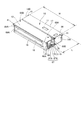
- FIG. 4 is a diagram in which the top plate 12 is removed from the unit case 11.
- the inside of the unit case 11 is a partition plate 55 provided substantially perpendicularly to the top plate 12 and the bottom plate 13, and houses the blower chamber R ⁇ b> 1 that houses the blower 50 and the indoor heat exchanger 60. It is divided into heat exchange chamber R2.
- the partition plate 55 is formed of a metal plate or the like, and blocks the air flow between the air blowing chamber R1 and the heat exchange chamber R2.
- the partition plate 55 is provided with an opening 55A, and an air blowing port (blow-out port) 50D of the blower 50 is connected to the opening 55A and exposed to the heat exchange chamber R2.
- a sirocco fan that is a centrifugal blower is used as the blower 50.
- the blower 50 is configured such that a cylindrical fan body 50A having a large number of blades is accommodated in a fan case 50B.
- the blower 50 includes a motor shaft 50C extending in the axial direction of the fan body 50A.
- the motor shaft 50 ⁇ / b> C is connected to the fan motor 20, and the fan main body 50 ⁇ / b> A is rotated by driving the fan motor 20.
- the number of blowers 50 accommodated in the blower chamber R1 can be appropriately changed according to the dimensions of the unit case 11 (the output capacity of the indoor unit 5).
- the blower chamber R1 is provided with a plurality of blowers 50 connected by a single motor shaft 50C, and the plurality of blowers 50 are similarly rotationally driven by the single fan motor 20.
- the structure provided with the fan motor 20 in each of the some air blower 50 may be sufficient.
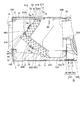
- the indoor heat exchanger 60 includes a flat plate-like upper heat exchange part 61 and a flat plate-like lower heat exchange part 62.
- the upper heat exchanging portion 61 and the lower heat exchanging portion 62 are combined and connected in a substantially square shape in a side view.
- the indoor heat exchanger 60 is configured by connecting the two plate-shaped heat exchange parts 61 and 62 in a substantially square shape in a side view. The height of the heat exchanger can be kept low and the heat exchange area can be increased compared to the case where the heat exchanger is arranged vertically.
- the upper heat exchanging portion 61 and the lower heat exchanging portion 62 are both fin-and-tube heat exchangers, and are arranged with a space between the pair of tube plates extending in the ventilation direction and the tube plates.
- the tubes are arranged in a plurality of rows in the front and rear (three rows in the present embodiment) and in a plurality of stages in the vertical direction, and are connected as one refrigerant pipe by a U-shaped portion (U vent) provided at the end of each tube.
- the upper heat exchanging portion 61 has an upper end portion 61 ⁇ / b> C extending to the lower surface side of the top plate 12.
- the lower heat exchanging part 62 is placed on a drain pan 70 whose lower end part 62C will be described later. Accordingly, the heat exchange chamber R2 is divided by the indoor heat exchanger 60 into a primary side chamber 65A on the upstream side of the indoor heat exchanger 60 and a secondary side chamber 65B on the downstream side of the indoor heat exchanger 60. Further, the upper heat exchanging portion 61 and the lower heat exchanging portion 62 are formed with the same width, and are accommodated almost fully in the unit width W.
- the upper heat exchanging portion 61 and the lower heat exchanging portion 62 are the lower end portion of the upper heat exchanging portion 61 on the air inflow side surface 62A which is the surface facing the primary side chamber 65A of the lower heat exchanging portion 62.
- (Lower end) 61A rides on and is placed in a stacked state.
- the upper heat exchange unit 61 and the lower heat exchange unit 62 thus overlap the lower end portion (lower end) 61A of the upper heat exchange unit 61 on the air inflow side surface 62A of the lower heat exchange unit 62.
- These are connected in a substantially square shape in a side view at substantially right angles to each other.
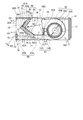
- the top 60 ⁇ / b> A of the “ ⁇ ” shape of the indoor heat exchanger 60 is formed by the corner on the outlet 18 side of the upper end (upper end) 62 ⁇ / b> B of the lower heat exchange unit 62.
- the upper heat exchange unit 61 is disposed closer to the blower 50 side, that is, the primary side chamber 65A side than the upper end portion 62B of the lower heat exchange unit 62.
- a step 60 ⁇ / b> C having a step width W ⁇ b> 1 is formed between the air outflow side surface 61 ⁇ / b> B of the upper heat exchange portion 61 and the upper end portion 62 ⁇ / b> B of the lower heat exchange portion 62.
- Drain water such as condensed water, that is generated in the upper heat exchange unit 61 and flows along the outflow side surface 61B under its own weight, flows out from the air outflow side surface 61B of the upper heat exchange unit 61 and the upper end portion 62B of the lower heat exchange unit 62. It is received by the step 60 ⁇ / b> C formed between and flows along the surface of the lower heat exchange unit 62. Thereby, it is possible to prevent the drain water generated in the upper heat exchange part 61 from being scattered from the connecting part 60 ⁇ / b> B between the upper heat exchange part 61 and the lower heat exchange part 62.
- the blower 50 is arranged so that the blower port 50D is provided obliquely downward so that the blowing direction from the blower port 50D is directed to the connecting portion 60B between the upper heat exchange unit 61 and the lower heat exchange unit 62.
- the indoor heat exchanger 60 is configured such that the number of tube stages of the upper heat exchange unit 61 is six.
- the indoor heat exchanger 60 is configured such that the number of tube stages of the lower heat exchange unit 62 is ten. That is, the upper heat exchange unit 61 and the lower heat exchange unit 62 are formed with the same thickness and the same width, and the heat exchange area of the lower heat exchange unit 62 is the heat exchange of the upper heat exchange unit 61. It is formed larger than the area.
- the heat exchange area of the upper heat exchange unit 61 is set to approximately 60% of the heat exchange area of the lower heat exchange unit 62.
- the upper heat exchange unit The amount of air passing through 61 and the lower heat exchange section 62 can be made substantially the same. Therefore, the temperature difference in the heat exchange surface between the upper heat exchange unit 61 and the lower heat exchange unit 62 can be reduced, and the heat exchange efficiency in the indoor heat exchanger 60 can be made uniform.
- the indoor heat exchanger 60 may have a configuration in which the open side of the U-shape is arranged in a direction facing the air outlet 50D of the blower 50, as shown in FIGS. Although not shown in the drawing, the configuration may be such that the apex 60 ⁇ / b> A side of the “ ⁇ ” shape is arranged in a direction facing the blower opening 50 ⁇ / b> D of the blower 50.
- the indoor heat exchanger 60 is arranged such that the inclination ⁇ of the lower heat exchange section 62 with respect to the horizontal direction does not become smaller than a predetermined angle, for example, 37 degrees.
- a drain pan 70 that receives drain water from the indoor heat exchanger 60 is disposed below the indoor heat exchanger 60.
- the drain pan 70 covers the entire bottom surface of the heat exchange chamber R ⁇ b> 2 and is supported by the bottom plate 13.
- the drain pan 70 is made of foamed polystyrene, and the inside of the indoor heat exchanger 60 that receives the drain water is covered with a resin sheet or the like for waterproofing and mold prevention. Thereby, the drain pan 70 can be reduced in weight.
- the drain pan 70 is formed with a drain pool 70A having a bottom portion that is one step lower.
- the suction port of the drain pump 78 is disposed in the drain reservoir 70A.
- the drain pan 70 is formed with a placement portion 73 on which a part of the lower end portion 62C of the lower heat exchange portion 62 is placed.
- the cushioning material may extend substantially fully in the width direction of the drain pan 70.
- the bottom plate 13 is divided into a blower chamber side bottom plate 13B that covers the bottom surface on the blower chamber R1 side, and a heat exchange chamber side bottom plate 13A that covers the bottom surface on the heat exchange chamber R2 side.
- the drain pan 70 is detachably provided from the unit case 11 by removing the heat exchange chamber side bottom plate 13A.
- the drain pan 70 is formed in a box shape with four side surfaces rising from the bottom surface.
- a plurality of positioning plates 74 with which the upper end of the side surface of the drain pan 70 abuts are provided at predetermined intervals in the width direction of the unit case 11. That is, the drain pan 70 is held in a state of being sandwiched between the positioning plate 74 and the heat exchange chamber side bottom plate 13A.
- the heat exchange chamber side bottom plate 13A can be removed and easily detached from the bottom surface side of the unit case 11. Can do.
- the beads 71 and 72 described above are formed on the heat exchange chamber side bottom plate 13 ⁇ / b> A.
- the bead 71 is provided at a position corresponding to the placement portion 73 of the drain pan 70 where the lower end portion 62C of the lower heat exchange portion 62 is placed. That is, with the indoor heat exchanger 60, the drain pan 70, and the heat exchange chamber side bottom plate 13 ⁇ / b> A attached to the unit case 11, the lower end portion 62 ⁇ / b> C of the lower heat exchange portion 62 and the placement portion 73 of the drain pan 70 come into contact.
- the portion and the bead 71 of the heat exchange chamber side bottom plate 13A are configured so as to be lined up and down substantially vertically.
- the bead 72 is provided at a position corresponding to the positioning plate 74 attached to the partition plate 55.
- the positioning plate 74 attached to the partition plate 55, the side surface of the drain pan 70, and the bead 72 are vertically up and down. It is configured to line up.
- the partition plate 55 includes an upper partition plate 55B and a lower partition plate 55C.
- the lower partition plate 55C includes a connection portion 74B that is bonded to the upper partition plate 55B by bending a single plate into a substantially L shape, and a bottom plate portion 74C that forms part of the bottom surface of the unit case 11. Is integrated.
- a positioning plate 74 is formed integrally with the lower partition plate 55C.
- the positioning plate 74 has a plurality of extending portions provided at a predetermined interval in the width direction of the unit case 11 at the upper portion of the connection portion 74B, substantially perpendicular to the connection portion 74B, and in the direction opposite to the bottom plate portion 74C. It is formed by bending it.
- one side in the depth L direction of the unit case 11 extends from the partition plate 55 to the air blowing chamber R1 side.
- the one side of the heat exchange chamber side bottom plate 13A is fixed to the bottom plate portion 74C of the lower partition plate 55C from the bottom surface side with a plurality of screws 3 at predetermined intervals in the width direction of the unit case 11. .
- the blowout side panel 16 is folded in the upper and lower sides in the unit case 11 in a substantially U shape in a sectional view, and a top portion 16A and a bottom portion 16B are formed.
- the other side of the heat exchange chamber side bottom plate 13A is fixed by being screwed with a plurality of screws 3 at a predetermined interval in the width direction of the unit case 11 from the bottom surface side.
- the heat exchange chamber side bottom plate 13A is screwed with the screw 3 in a state where both end portions in the length direction are pressed against the bottom portion 16B and the bottom plate portion 74C from the bottom surface side of the unit case 11. .
- the top plate 12 is fixed to the top portion 16A with screws. Between the upper end 60 ⁇ / b> D of the indoor heat exchanger 60 and the top plate 12, a heat insulating material 21 formed of a foam material or the like that covers the upper surface of the secondary side chamber 65 is attached.
- the drain pan 70 is held in a state of being sandwiched between the lower end 62 ⁇ / b> C of the lower heat exchange unit 62 and the bead 71 and between the positioning plate 74 and the bead 72. That is, the beads 71 and 72 serve to fix the drain pan 70 as an auxiliary. Therefore, it is possible to prevent the drain pan 70 from being lifted by the static pressure on the primary side chamber 65A side with a simple configuration.
- one end side fixing member 63A and the other end side fixing member 63B are attached to both width end portions in the width direction of the indoor heat exchanger 60, respectively.
- the fixing members 63A and 63B are formed of resin.
- the indoor heat exchanger 60 is fixed integrally with the fixing members 63A and 63B so as to be sandwiched between the fixing members 63A and 63B.
- One end portion of the indoor heat exchanger 60 is provided with a fixing portion 8 formed integrally with a tube plate attached to the one end portion (see FIG. 6).
- the fixing unit 8 includes an upper end portion 61C of the upper heat exchange unit 61, an air outflow side surface 61B of the upper heat exchange unit 61, and an air outflow side surface 62D of the lower heat exchange unit 62, respectively. Extend outside.
- the one end side fixing member 63A is screwed to the fixing portion 8 with a screw 8a and fixed to the indoor heat exchanger 60.
- FIG. 8 is a view of the one-end-side fixing member 63A as viewed from the direction of the arrow shown in FIG.
- the one end side fixing member 63A is formed with a plurality of vent holes 81 into which U vents protruding from the tube plate of the indoor heat exchanger 60 are inserted.
- Each vent hole 81 is formed in correspondence with the position of the U vent protruding from the tube sheet.
- a peripheral wall 81A is formed along the outer periphery.
- the peripheral wall 81A is formed at substantially the same height as the height of the U vent inserted into the vent hole 81.
- the width W2 of the one end side fixing member 63A is formed to be substantially the same as the height of the U vent inserted into the vent hole 81.
- the other end side fixing member 63 ⁇ / b> B is attached to the other end side of the indoor heat exchanger 60.
- the other end side fixing member 63B is fixed to the indoor heat exchanger 60 so as not to interfere with the auxiliary refrigerant pipe 67, the electric expansion valve 91, the silencer 92, and the like extending from the indoor heat exchanger 60.
- the auxiliary refrigerant pipe 67 includes a gas pipe auxiliary refrigerant pipe 67A for connection to the gas pipe and a liquid pipe auxiliary refrigerant pipe 67B for connection to the liquid pipe.
- the auxiliary refrigerant pipe 67 is gathered on the other end side fixing member 63B side. That is, the indoor heat exchanger 60 is configured so that there is no protruding member outside the one end side fixing member 63A.
- the other-end-side fixing member 63B is substantially along the air outflow side surfaces 61B and 62D of the upper heat exchange unit 61 and the lower heat exchange unit 62. It has the groove
- the other end side fixing member 63B extends from the secondary side of the indoor heat exchanger 60 to the tube plate 9 along the groove 25A along the air outflow side surfaces 61B and 62A of the upper heat exchange unit 61 and the lower heat exchange unit 62. Fixed to.
- the tube plate 9 includes a plate material 9 ⁇ / b> A that is integrally formed with the tube plate 9 and extends from the tube plate 9.
- the plate material 9 ⁇ / b> A is inserted into the recess 26 formed in the groove 25.
- the plate member 9 ⁇ / b> A and the recess 26 are screwed together with screws 7, whereby the other end side fixing member 63 ⁇ / b> B is fixed integrally with the indoor heat exchanger 60.
- the other end side fixing member 63B includes the groove 25 along the tube plate 9 on the secondary side of the indoor heat exchanger 60, the auxiliary refrigerant pipe 67 connected to the indoor heat exchanger 60, electric expansion It can be mounted without interfering with components such as the valve 91 and the silencer 92.
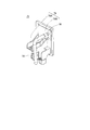
- the indoor heat exchanger 60, the fixing members 63A and 63B, and the auxiliary refrigerant pipe 67 are integrated as an indoor heat exchange unit 80.
- the indoor heat exchange unit 80 is attached to the unit case 11 so that attachment or detachment is possible.
- screw holes 64 ⁇ / b> A and 64 ⁇ / b> B for fixing the indoor heat exchange unit 80 to the unit case 11 with screws are formed in the fixing members 63 ⁇ / b> A and 63 ⁇ / b> B.
- the screw hole 64 ⁇ / b> A is provided at a position corresponding to the screw hole 69 ⁇ / b> B formed in the top plate 12 of the unit case 11.
- the indoor heat exchange unit 80 is fixed to the top plate 12 of the unit case 11 by screwing the screw hole 69B and the screw hole 64A with screws (not shown).
- the screw hole 64A may be formed integrally with the one end side fixing member 63A as provided in the one end side fixing member 63A, or the other end as provided in the other end side fixing member 63B. You may form in the metal bracket etc. which are integrally fixed to the side fixing member 63B.
- the fixing members 63A and 63B are provided with a boss portion 64C in which a screw hole 64B is formed, and a screw thread into which a screw is screwed through the screw hole 64A is formed inside the boss portion 64C. .
- the screw hole 64B is provided at a position corresponding to the screw hole 69A formed in the outlet side panel 16 of the unit case 11.
- a plurality of screw holes 69 ⁇ / b> A are provided vertically in the vicinity of the air outlet 18 formed to have substantially the same width as the indoor heat exchanger 60.
- the indoor heat exchange unit 80 is fixed to the blow-out side panel 16 of the unit case 11 by screwing the screw holes 69A and the screw holes 64B with screws.
- the fixing members 63A and 63B are fixed in contact with the top plate 12 and the blow-out side panel 16, and the heat exchange chamber R2 is primary in the upstream side of the indoor heat exchanger 60 by the indoor heat exchange unit 80. It plays a role of partitioning the side chamber 65A and the secondary side chamber 65B. Since the fixing members 63A and 63B are formed of a resin material having excellent heat insulation properties, the secondary side chamber 65B and the primary side chamber 65A are insulated without attaching a heat insulating material to the fixing members 63A and 63B. be able to.
- the secondary side chamber 65B can be insulated from the atmosphere of the secondary side chamber 65B and the unit body 10 simply by attaching a heat insulating material to the top plate 12 and below the outlet 18 of the blowout side panel 16. it can. Therefore, the usage fee of the heat insulating material can be reduced, and the work of attaching the heat insulating material can be reduced.
- the indoor heat exchanger 60 is fixed to the top plate 12 and the blowout side panel 16 using screw holes provided in fixing members 63A and 63B attached to both side ends in the width direction. Thereby, compared with the case where the indoor heat exchanger 60 is fixed to the partition plate 55, there is no protrusion of the fixture from the indoor heat exchanger 60 to the blower 50 side, and the blower port 50 ⁇ / b> D of the blower 50 and the indoor heat exchanger The ventilation resistance between 60 can be reduced.
- the indoor heat exchange unit 80 is fixed to the top plate 12 and the blowout side panel 16 using screw holes 64A and 64B provided in fixing members 63A and 63B attached to both end portions in the width direction. It can be fixed inside the main body 10.
- the fixing members 63A and 63B serve to partition the primary side chamber 65A and the secondary side chamber 65B on both side surfaces of the indoor heat exchanger 60, and fix the indoor heat exchanger 60 in the unit body 10.
- the number of parts can be reduced as compared with a case where a fixture for fixing the indoor heat exchanger 60 is provided on the partition plate 55 and the indoor heat exchanger 60 is fixed inside the unit body 10.
- the mounting workability can be improved.
- there is no jumping out of the fixture from the indoor heat exchanger 60 to the blower 50 side and the ventilation resistance in the primary side chamber 65A of the heat exchange chamber R2 can be reduced.
- the one end side fixing member 63A attached to one end side of the indoor heat exchanger 60 is provided with the vent hole 81 into which the U vent protruding from the tube plate 9 is inserted, thereby performing the indoor heat exchange.
- the other end side fixing member 63B attached to the other end side of the vessel 60 was provided with a groove 25 formed in a shape along the secondary side shape of the tube sheet 9. Accordingly, the fixing members 63A and 63B can be attached so as to sandwich the indoor heat exchanger 60 from both ends without interfering with members protruding outward from both ends of the indoor heat exchanger 60.
- the indoor heat exchanger 60 is integrated into the unit main body 10 integrally with the auxiliary refrigerant pipe 67 connected to the indoor heat exchanger 60 using the pair of fixing members 63A and 63B formed in different shapes. Since it can be detachably provided, the maintainability of the indoor heat exchanger 60 can be improved. Although details will be described later, the indoor heat exchange unit 80 is provided so as to be inserted into the heat exchange chamber R2 from the lower opening 40 shown in FIG.
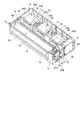
- FIG. 10 is a view of the unit main body 10 with the heat exchange chamber side bottom plate 13 ⁇ / b> A and the drain pan 70 removed, as viewed obliquely from below.
- the lower opening (opening) 40 extending over the entire bottom of the heat exchange chamber R2 is formed on the lower surface of the unit case 11 by removing the heat exchange chamber side bottom plate 13A and the drain pan 70.
- a lid body 68, a fixture 79 for fixing the drain pump, and a maintenance panel 56 are separately formed and detachably attached.
- FIG. 10 shows a state where the lid 68 is removed from the unit case 11 for convenience of explanation.
- the side plate 14A of the unit case 11 is provided with a notch 68C to which the lid 68 is attached.
- the notch 68 ⁇ / b> C is formed to open below the unit case 11 and communicate with the lower opening 40.
- the auxiliary refrigerant pipe 67 protruding outward from the side plate 14A from the indoor heat exchanger 60 is inserted into the heat exchange chamber R2 from the lower opening 40 integrally with the indoor heat exchanger 60 through the notch 68C.
- the side plate 14A is formed with semicircular inverted U-shaped grooves 66A and 66B that open downward so that the auxiliary refrigerant pipe can be inserted into the notch 68C.
- Each inverted U-shaped groove 66 ⁇ / b> A, 66 ⁇ / b> B is formed at a position corresponding to the auxiliary refrigerant pipe 67 inserted through the notch 68.
- the lid body 68 is formed with U-shaped grooves 68A and 68B that open upward at positions corresponding to the inverted U-shaped grooves 66A and 66B.
- the lid body 68 is fixed to the side plate 14 ⁇ / b> A with screws (not shown) inserted into screw holes 68 ⁇ / b> D and 68 ⁇ / b> D provided in the lower portion of the lid body 68. Accordingly, the lid body 68 closes the notch 68C of the side plate 14A.
- the lid 68 is formed with a handle 68E extending over the length L2 of the lid 68 above the screw holes 68D and 68D.
- the lid body 68 is configured to be able to be attached to and detached from the side plate 14A by pressing the handle 68E by hand.
- the auxiliary refrigerant pipe 67 is held on the side plate 14A by the cooperation of the U-shaped grooves 68A and 68B of the lid body 68 and the reverse U-shaped grooves 66A and 66B of the side plate 14A. Is done.
- a water injection opening 85 is formed in the lid 68 between the U-shaped groove 68B and the handle 68E.
- the water injection opening 85 is normally closed with a lid 86 fixed to the lid body 68 with a screw or the like.
- the lid 86 is removed from the water injection opening 85 and the heat exchange chamber R2 is passed through the water injection opening 85. It is possible to check the flow of drain water by pouring water inside.
- the lid 68 can be removed from the unit case 11 by removing the screws screwed into the screw holes 68D, 68D, and the notch 68C can be removed from the side plate 14A by removing the lid 68 from the side plate 14A. Communicate with. Thereby, the bottom surface side of the unit case 11 is opened so that the indoor heat exchange unit 80 can be pulled out from the unit case 11 and removed without removing the auxiliary refrigerant pipe 67 from the indoor heat exchange unit 80.
- the pump-down operation of the built-in type air conditioner 1 is performed.
- the pump-down operation although not shown, all the refrigerant in the indoor heat exchanger 60 is collected by the outdoor unit or the refrigerant recovery machine, the valve is closed, and the indoor heat exchanger 60 is disconnected from the refrigerant circuit.
- the heat exchange chamber side bottom plate 13A, the drain pan 70, and the lid 68 are removed from the unit case 11 through the opening of the ceiling plate 33 from which the ceiling panel 35 is removed. Thereby, a lower opening 40 for removing the indoor heat exchange unit 80 downward is formed in the lower part of the unit case 11.
- the drain pipe holder 76 and the drain drain pipe 77 penetrating the drain pipe holder 76 are put together with the drain pan 70 from the lower opening 40 from which the bottom plate 13 of the unit case 11 is removed. Can be removed.
- the screw 4 fixing the indoor heat exchange unit 80 to the unit case 11 is removed. Specifically, the screw 4 screwed into the screw hole 64B and the screw hole 69A is removed from the outside of the unit case 11, and the screw 4 screwed into the screw hole 64A and the screw hole 69B is removed from the inside of the unit case 11. Remove from.
- the indoor heat exchange unit 80 can be pulled out integrally below the unit case 11 via the lower opening 40 of the heat exchange chamber R2 and removed from the unit body 10. According to this configuration, the unit case 11 is suspended from the ceiling space 34 as shown in FIG. 1, that is, from the unit case 11 to the bottom plate as shown in FIG.
- the indoor heat exchange unit 80 can be removed from the unit case 11 by simply removing a total of six screws (three on each side) 4A and 4B screwed into the screw holes 64A and 64B. 11 can be removed. Therefore, the indoor heat exchange unit 80 can be easily removed from the conditioned room 2 side by removing the ceiling panel 35. Thereby, the work in the ceiling space 34 with a limited work space can be reduced, and the maintainability of the indoor heat exchanger 60 can be improved.
- a pump unit 75 is attached to the side plate 14A in the vicinity of the pipe presser 68.
- the pump unit 75 integrally includes a drain pump 78 and a fixture 79 to which the drain pump 78 is fixed.
- a pump fixing portion 79A to which the drain pump 78 is fixed and a lid portion 79B for closing the pump mounting opening 75A for mounting the pump unit 75 formed on the side plate 14A are integrally formed with resin.
- a drain pipe 76 is connected between the drain pump 78 and the lid 79B for draining the water sucked from the drain pan 70 by the drain pump 78 to the outside of the unit case 11.
- the pump unit 75 is integrally provided with a drain pump 78 and a fixture 79 so as to be detachable from the side plate 14A, and the lid 79B is fixed to the side plate 14A with screws or the like.
- the drain pump 78 can be easily detached from the unit case 11 integrally with the pump unit 75. Therefore, even after the piping construction in which the auxiliary refrigerant pipe 67 is connected to the indoor heat exchanger 60, the pump unit 75 can be easily removed from the unit case 11, and the drain pump 78 can be easily maintained.
- the unit main body 10 configured to accommodate the heat exchanger 60 and the blower 50 is provided, and the heat exchanger 60 has a substantially square shape in a side view. It includes an upper heat exchanging part and a lower heat exchanging part to be connected, and is provided with a blower port 50D of the blower 50 facing the apex 60A of the square shape.
- the heat exchanging part 61 is accommodated to the same width and the unit width W is almost fully accommodated, and the lower end part 61A of the upper heat exchanging part 61 is arranged on the lower heat exchanging part 62 at the apex 60A of the substantially square shape.
- the upper heat exchange unit 61 is arranged closer to the blower 50 than the upper end 62B of the lower heat exchange unit 62, and the outflow of air from the upper heat exchange unit 61
- a step 60 ⁇ / b> C is provided between the side surface 61 ⁇ / b> B and the upper end portion 62 ⁇ / b> B of the lower heat exchange unit 62.
- the drain water generated in the upper heat exchanging portion 61 and flowing under its own weight along the outflow side surface 61D is received by the step 60C formed in the connecting portion 60B between the upper heat exchanging portion 61 and the lower heat exchanging portion 62. And flows through the lower heat exchange section 62. Therefore, it is possible to prevent the drain water from splashing from the upper heat exchanging portion 61 and the connecting portion 60B of the lower heat exchanging portion 62.
- the unit main body 10 configured to accommodate the indoor heat exchanger 60 and the blower 50 is provided, and the indoor heat exchanger 60 is connected to a substantially square shape in a side view.
- the upper side heat exchanging part 61 and the lower side heat exchanging part 62 are provided, and the blower port 50D of the blower 50 is provided so as to face the apex 60A of the square shape.
- the heat exchanging part 61 is accommodated to have the same width and the unit width W is almost full, and the heat exchanging area of the lower heat exchanging part 62 is set larger than that of the upper heat exchanging part 61.
- the amount of air passing through the upper heat exchange unit 61 and the lower heat exchange unit 62 can be made substantially the same while increasing the capacity (heat exchange area) of the indoor heat exchanger 60. Therefore, the temperature difference in the heat exchange surface between the upper heat exchange unit 61 and the lower heat exchange unit 62 can be reduced, and the heat exchange efficiency of the indoor heat exchanger 60 can be made uniform.
- the heat exchange area of the upper heat exchange unit 61 is set to approximately 60% of the heat exchange area of the lower heat exchange unit 62.
- the amount of air passing through the upper heat exchange unit 61 and the lower heat exchange unit 62 can be made substantially the same. Therefore, the temperature difference in the heat exchange surface between the upper heat exchange unit 61 and the lower heat exchange unit 62 can be reduced, and the heat exchange efficiency of the indoor heat exchanger 60 can be made uniform.
- the inside of the unit body 10 is divided into a blower chamber R1 in which the blower 50 is accommodated and a heat exchange chamber R2 in which the indoor heat exchanger 60 is accommodated.
- a drain pan 70 covering the entire bottom of R2 was provided, and the lower end 62C of the lower heat exchange unit 62 was placed on the drain pan 70.
- the blower 50 can be provided substantially fully in the height direction of the blower chamber R ⁇ b> 1, the size of the unit body 10 in the height direction can be suppressed, and the upper heat exchange unit 61 and the lower heat exchange unit 62 can The drain water can be collected by a drain pan 70.
- the inside of the unit body 10 is partitioned by the partition plate 55 into a heat exchange chamber R2 that houses the heat exchanger 60 and a blower chamber R1 that houses the blower 50,
- a heat exchange chamber R2 that houses the heat exchanger 60
- a blower chamber R1 that houses the blower 50
- Resin fixing members 63A and 63B for fixing the heat exchanger 60 inside the unit body 10 are provided. Thereby, there is no need to separately provide a fixing member for fixing the heat exchanger 60 in the unit case 11, for example, by protruding from the partition plate 55. Therefore, the heat exchanger 60 can be fixed in the unit body 10 with a simple structure, and the number of parts can be reduced and the mounting workability can be improved.
- the vent hole 81 through which the U-shaped tube of the heat exchanger 60 passes is provided in the fixing member 63A on one end side of both ends of the heat exchanger 60, and the other end side is provided.
- a square-shaped groove 25 formed along the shape of the heat exchanger 60 is provided in the fixing member 63 ⁇ / b> B, and the refrigerant pipe of the heat exchanger is passed through the groove 25.
- the one end side fixing member 63A is positioned and temporarily fixed by passing the U-shaped tube of the heat exchanger 60 through the vent hole 81. Therefore, the one end side fixing member 63A can be easily fixed to the heat exchanger 60 integrally.
- the other end side fixing member 63 ⁇ / b> B includes a groove 25 formed along the shape of the heat exchanger 60, and the other end side fixing member 63 ⁇ / b> B interferes with the auxiliary refrigerant pipe 67 connected to the heat exchanger 60. Without being fixed to the heat exchanger 60 easily.
- the inside of the unit body 10 is partitioned by the partition plate 55 into a heat exchange chamber R2 that houses the heat exchanger 60 and a blower chamber R1 that houses the blower 50,
- the heat exchanger 60 is desorbed from the opening 40 on the lower surface of the unit body 10 into the heat exchange chamber R2.
- the auxiliary refrigerant pipe 67 of the heat exchanger 60 protruding outward from the side plate 14A is formed on the side plate 14A of the unit body 10 so as to be integrated with the heat exchanger 60 from the opening 40 side.
- Reverse U-shaped grooves 66A and 66B that are open downward so as to be inserted therein are provided.
- a lid body 68 having U-shaped grooves 68A and 68B is attached to the side plate 14A, and the U-shaped grooves 68A and 68B of the lid body 68 are attached.
- side plate 1 Inverted U-shaped groove 66A of the A, by 66B in cooperation with the auxiliary refrigerant pipe 67 and can be held to the side plate 14A.
- the auxiliary refrigerant pipe 67 is connected to the side plate 14A by the cooperation of the U-shaped grooves 68A and 68B of the lid body 68 and the reverse U-shaped grooves 66A and 66B of the side plate 14A. Can be held in. Further, when the heat exchanger 60 is detached, the cover body 68 is removed from the side plate 14A, so that the heat exchanger 60 and the auxiliary refrigerant pipe 67 are integrated together without removing the auxiliary refrigerant pipe 67 from the heat exchanger 60. 10 can be easily detached from the opening 40 on the lower surface. Therefore, the maintainability of the heat exchanger 60 can be improved.
- the unit main body 10 includes the drain pan 70 that receives the drain water generated by the heat exchanger 60, and the drain water accumulated in the drain pan 70 through the drain pipe 76.
- a drain pump 78 for draining outside the unit main body 10 is built in, and a pump unit 75 in which the drain pump 78 and the drain pipe 76 are integrally combined is provided in the vicinity of the lid 68 on the side surface 14 of the unit main body 10. It is arranged to be detachable. Thereby, the drain pump 78 can be easily detached from the unit body 10 integrally with the pump unit 75.
- the pump unit 75 can be easily detached from the unit body 10 even after the heat exchanger 60 and the auxiliary refrigerant pipe 67 are installed. Therefore, the drain pump 78 can be easily maintained.
- the heat exchanger 60 is provided at both ends, and is inserted into the heat exchange chamber R2 from the opening 40 side integrally with the heat exchanger 60, and the unit body 10 is blown out.
- Resin fixing members 63A and 63B that are fixed to the side panel 16 and the top plate 12 and fix the heat exchanger 60 to the inside of the unit body 10 are provided.
- the fixing members 63A, 63B are removed from the front plate 16 and the top plate 12, so that the heat exchanger 60 is integrated with the fixing members 63A, 63B in the opening on the lower surface of the unit body 10. 40 can be easily taken out. Therefore, the maintainability of the heat exchanger 60 can be improved.
- the heat exchanger 60 includes the upper heat exchanging portion 61 and the lower heat exchanging portion 62 that are connected to each other when viewed in a side view,
- the blower outlet 50D of the blower 50 was provided so as to face each other. Accordingly, the capacity (heat exchange area) of the heat exchanger 60 can be increased without changing the height of the unit case 11.
- the open side of the square shape of the indoor heat exchanger 60 is opposed to the outlet 50D of the blower 50.
- the shape of the air inlet side of the indoor heat exchanger 60 can be made to correspond to the distribution of the air volume from the blower 50, and the efficiency of heat exchange can be improved.
- the open side of the square shape of the indoor heat exchanger 60 is directed to the downstream side of the indoor heat exchanger 60.
- the blower 50 is a sirocco fan that is a centrifugal blower, a large static pressure can be obtained, and the indoor heat exchanger 60 and the ceiling plate are provided downstream of the blower 50. Even with a built-in type air conditioner having a relatively long blowing duct 54 extending to 33, a large air flow rate can be obtained.
Abstract
Provided is a built-in type air conditioning device in which the maintainability and efficiency of an indoor heat exchanger are improved. A heat exchanger (60) includes an upper side heat exchanger and a lower side heat exchanger coupled in a substantially dogleg shape in a side view, wherein the lower end of the upper side heat exchanger is disposed on and overlapped with the lower side heat exchanger at the bent portion of the dogleg shape. The heat exchange area of the lower side heat exchanger is set to be larger than that of the upper side heat exchanger. Reverse U-shaped grooves (66A, 66B) that open downwards are provided so that an auxiliary refrigerant pipe (67) of the heat exchanger (60) can be inserted into a heat exchange chamber integrally with the heat exchanger (60). At both ends of the heat exchanger (60), fixing members (63A, 63B) made of resin are also provided that are fixed to the front panel (16) and top panel (12) of a unit main body (10) and used for fixing the heat exchanger (60) to the inside of the unit main body (10).
Description
本発明は、建物の天井部に設置された室内機を備えるビルトイン型空気調和装置に関する。
The present invention relates to a built-in type air conditioner including an indoor unit installed on a ceiling of a building.
従来、建物の天井裏空間等の天井部に設置される室内機と、当該室内機に冷媒配管を介して接続される室外機とを備えるビルトイン型空気調和装置が知られている。この種のビルトイン型空気調和装置では、室外機に圧縮機及び室外熱交換器を収容し、室内機に室内熱交換器及び送風機を収容している。圧縮機、室外熱交換器、及び室内熱交換器は、冷媒配管で接続され、冷媒回路を構成している。そして、送風機により室内熱交換器に送風するとともに室内熱交換器内を流れる冷媒と熱交換した調和空気を吹出ダクトを介して被調和室に吹き出している(例えば、特許文献1参照)。ところで、ビルトイン型空気調和装置の室内機は、設置スペースが限られている天井部に設置される。このため、室内機の高さを抑えつつ、室内熱交換器の容量を大きくするために、平板状の2枚の室内熱交換器(上側熱交換部と下側熱交換部)を側面視でくの字になるように連結して配置しているものがある。
2. Description of the Related Art Conventionally, a built-in type air conditioner including an indoor unit installed in a ceiling part such as a ceiling space of a building and an outdoor unit connected to the indoor unit via a refrigerant pipe is known. In this type of built-in air conditioner, a compressor and an outdoor heat exchanger are accommodated in the outdoor unit, and an indoor heat exchanger and a blower are accommodated in the indoor unit. The compressor, the outdoor heat exchanger, and the indoor heat exchanger are connected by a refrigerant pipe to form a refrigerant circuit. And the conditioned air which ventilated by the air blower to the indoor heat exchanger and heat-exchanged with the refrigerant | coolant which flows through the inside of an indoor heat exchanger is blown out to the to-be-conditioned room via the blowing duct (for example, refer patent document 1). By the way, the indoor unit of a built-in type air conditioner is installed in a ceiling portion where installation space is limited. For this reason, in order to increase the capacity of the indoor heat exchanger while suppressing the height of the indoor unit, the two flat plate-like indoor heat exchangers (the upper heat exchanging portion and the lower heat exchanging portion) are viewed from the side. Some of them are connected so as to form a square shape.
しかしながら、室内熱交換器を側面視でくの字に連結して配置した場合、上側熱交換部がドレンパンから離れた位置に配置される。そのため、上側熱交換部からのドレン水がくの字状の連結部から飛散して、送風機から送風される風で吹出口から吹き出す場合がある。また、側面視くの字状の室内熱交換器では、熱交換面内の各部に対する送風機の位置、或いは、距離が不均一になる。そのため、熱交換面内の各部で風速の違い、あるいは温度むらが生じ、室内熱交換器の熱交換効率を均一化することができないという問題がある。
また、側面視くの字状の室内熱交換器を室内機の内部に固定するためには、固定構造が複雑になる傾向があった。固定構造が複雑になると、固定具が室内機の風路内に飛び出し通風抵抗になる、あるいは、熱交換器の下流側の2次側室を、上流側の1次側室から区分けするとともに断熱するための部品点数が多くなり、取り付け作業性が悪くなっていた。また、このようなビルトイン型空気調和装置は、天井内に設置されるため、一度設置すると、メンテナンスのために空気調和装置を取り外すことは大変であった。 However, in the case where the indoor heat exchanger is connected to the cross-section when viewed from the side, the upper heat exchanger is disposed at a position away from the drain pan. Therefore, there is a case where drain water from the upper heat exchanging part scatters from the U-shaped connecting part and blows out from the outlet by the air blown from the blower. In addition, in a square-shaped indoor heat exchanger as viewed from the side, the position or distance of the blower with respect to each part in the heat exchange surface becomes uneven. Therefore, there is a problem that differences in wind speed or temperature unevenness occur in each part in the heat exchange surface, and the heat exchange efficiency of the indoor heat exchanger cannot be made uniform.
Moreover, in order to fix the indoor heat exchanger in the shape of a letter in a side view inside the indoor unit, the fixing structure tends to be complicated. When the fixing structure is complicated, the fixture jumps out into the air passage of the indoor unit and becomes resistance to ventilation, or the secondary side chamber on the downstream side of the heat exchanger is separated from the primary side chamber on the upstream side and insulated. The number of parts increased, and the installation workability became worse. Moreover, since such a built-in type air conditioner is installed in the ceiling, once installed, it is difficult to remove the air conditioner for maintenance.
また、ビルトイン型空気調和装置では、室内熱交換器に接続された冷媒配管や、この室内熱交換器で生成されドレンパンで受けたドレン水を排水するドレンポンプに繋がれた排水管を、例えばユニットケースの側板を貫通させて、ユニット本体から引き出している。そのため、室内熱交換器のメンテナンス時等で、室内熱交換器をユニット本体から取り外す場合には、狭い天井裏空間でこれらの冷媒配管並びに排水管を室内熱交換器やドレンポンプからユニット本体内で取り外す、或いは、冷媒配管ごとユニット本体を天井裏空間から取り外してから室内熱交換器をユニット本体から取り外す作業を行う必要があり、作業性が悪かった。
In the built-in type air conditioner, for example, a refrigerant pipe connected to the indoor heat exchanger or a drain pipe connected to a drain pump for draining drain water generated by the indoor heat exchanger and received by a drain pan is provided, for example, as a unit. The side plate of the case is passed through and pulled out from the unit body. For this reason, when removing the indoor heat exchanger from the unit main body during maintenance of the indoor heat exchanger, etc., these refrigerant pipes and drain pipes are connected to the inside of the unit main body from the indoor heat exchanger or drain pump in a narrow ceiling space. It was necessary to perform the work of removing the indoor heat exchanger from the unit body after removing or removing the unit body from the ceiling space together with the refrigerant piping, and the workability was poor.
本発明は、上述した従来の技術が有する課題を解消し、室内熱交換器の容量を大きくしつつ、熱交換器からドレン水が飛散するのを防止することができるビルトイン型空気調和装置を提供することを目的とする。また、本発明は、室内熱交換器の容量を大きくしつつ、熱交換効率を均一化することができるビルトイン型空気調和装置を提供することを目的とする。また、本発明は、上述した従来の技術が有する課題を解消し、簡単な構造かつ少ない部品で室内熱交換器を取り付けることができるビルトイン型空気調和装置を提供することを目的とする。また、本発明は、上述した従来の技術が有する課題を解消し、室内熱交換器のメンテナンス性を向上させたビルトイン型空気調和装置を提供することを目的とする。
The present invention provides a built-in type air conditioner that solves the problems of the above-described conventional technology and can prevent the drain water from scattering from the heat exchanger while increasing the capacity of the indoor heat exchanger. The purpose is to do. Another object of the present invention is to provide a built-in type air conditioner that can make the heat exchange efficiency uniform while increasing the capacity of the indoor heat exchanger. It is another object of the present invention to provide a built-in type air conditioner that can solve the above-described problems of the prior art and can be mounted with an indoor heat exchanger with a simple structure and a small number of parts. Another object of the present invention is to provide a built-in type air conditioner that solves the problems of the conventional techniques described above and improves the maintainability of the indoor heat exchanger.
上記目的を達成するために、本発明は、熱交換器及び送風機を収容して構成されるユニット本体を備え、前記熱交換器が側面視で略くの字に連結される上側熱交換部及び下側熱交換部を含み、くの字の頂点に対向させて前記送風機の吹き出し口を設け、前記ユニット本体内には、前記下側熱交換部および前記上側熱交換部を同じ幅としてユニット幅略一杯に収容し、前記略くの字の頂点では前記下側熱交換部の上に前記上側熱交換部の下端を重ねて配置したことを特徴とする。
In order to achieve the above object, the present invention comprises a unit main body configured to accommodate a heat exchanger and a blower, and the upper heat exchanging unit connected to the substantially square shape in a side view, and It includes a lower heat exchanging part, and is provided with a blower outlet of the blower so as to face the apex of the character, and in the unit body, the lower heat exchanging part and the upper heat exchanging part have the same width as the unit width. It is accommodated substantially fully, and the lower end of the upper heat exchanging portion is disposed on the lower heat exchanging portion at the apex of the substantially square shape.
また、本発明は、前記上側熱交換部は、前記下側熱交換部の上端よりも送風機側に寄せて配置され、前記上側熱交換部の空気の流出側面と、前記下側熱交換部の上端との間に段差を設けたことを特徴とする。
Further, in the present invention, the upper heat exchanging portion is disposed closer to the blower than the upper end of the lower heat exchanging portion, the air outflow side surface of the upper heat exchanging portion, and the lower heat exchanging portion A step is provided between the upper end and the upper end.
また、上記目的を達成するために、本発明は、熱交換器及び送風機を収容して構成されるユニット本体を備え、前記熱交換器が側面視で略くの字に連結される上側熱交換部及び下側熱交換部を含み、くの字の頂点に対向させて前記送風機の吹き出し口を設け、前記ユニット本体内には、前記下側熱交換部および前記上側熱交換部を同じ幅としてユニット幅略一杯に収容し、前記下側熱交換部の熱交換面積を前記上側熱交換部より大きく設定したことを特徴とする。
In order to achieve the above object, the present invention includes a unit main body configured to accommodate a heat exchanger and a blower, and the heat exchanger is connected to a substantially square shape in a side view. And a lower heat exchanging part, and the blower outlet of the blower is provided facing the apex of the character, and the lower heat exchanging part and the upper heat exchanging part have the same width in the unit body. The unit is accommodated in a substantially full width, and the heat exchange area of the lower heat exchange part is set larger than that of the upper heat exchange part.
また、本発明は、前記上側熱交換部の熱交換面積は、前記下側熱交換部の熱交換面積の略6割に設定されていることを特徴とする。
Further, the present invention is characterized in that the heat exchange area of the upper heat exchange part is set to approximately 60% of the heat exchange area of the lower heat exchange part.
また、本発明は、前記ユニット本体内を前記送風機が収容される送風室と、前記熱交換器が収容される熱交換室とに区分けし、前記熱交換室の底部全体を覆うドレンパンを設け、前記下側熱交換部の下端を前記ドレンパンに載置したことを特徴とする。
また、上記目的を達成するために、本発明は、ユニット本体の内側を、仕切板により、熱交換器を収容する熱交換室と、送風機を収容する送風室とに仕切り、前記送風機で吸い込んだ空気を、前記熱交換器で熱交換して吹き出すビルトイン型空気調和装置において、前記熱交換器の両端部に、前記ユニット本体の前板及び天板に固定されて、当該熱交換器を前記ユニット本体の内側に固定するための樹脂製の固定部材を設けたことを特徴とする。 Further, the present invention divides the inside of the unit body into a blower chamber in which the blower is accommodated and a heat exchange chamber in which the heat exchanger is accommodated, and a drain pan that covers the entire bottom of the heat exchange chamber is provided, The lower end of the lower heat exchange part is placed on the drain pan.
In order to achieve the above object, according to the present invention, the inside of the unit body is partitioned by a partition plate into a heat exchange chamber that houses a heat exchanger and a blower chamber that houses a blower, and is sucked by the blower. In a built-in type air conditioner that blows air by exchanging heat with the heat exchanger, the heat exchanger is fixed to the front plate and the top plate of the unit body at both ends of the heat exchanger, A resin-made fixing member for fixing inside the main body is provided.
また、本発明は、上記のビルトイン型空気調和装置において、前記熱交換器の両端のうち、一端側の固定部材に前記熱交換器のU字管が貫通するベント孔を設け、他端側の固定部材に前記熱交換器の形状に沿って形成されたくの字の溝を設け、前記溝から前記熱交換器の冷媒管を貫通させたことを特徴とする。
In the built-in type air conditioning apparatus according to the present invention, a vent hole through which the U-shaped tube of the heat exchanger passes is provided in a fixing member on one end side of both ends of the heat exchanger, The fixing member is provided with a U-shaped groove formed along the shape of the heat exchanger, and the refrigerant pipe of the heat exchanger is penetrated from the groove.
また、上記目的を達成するために、本発明は、ユニット本体の内側を、仕切板により、熱交換器を収容する熱交換室と、送風機を収容する送風室とに仕切り、前記送風機で吸い込んだ空気を、前記熱交換器で熱交換して吹き出すビルトイン型空気調和装置において、前記ユニット本体の下面の開口部から、前記熱交換器を、前記熱交換室内に脱着可能に形成し、前記ユニット本体の側板には、当該側板から外方に突出する前記熱交換器の冷媒管を、当該熱交換器と一体に前記開口部側から前記熱交換室内に挿入可能に下方を開口する逆U字溝が設けられ、U字溝を有した蓋体を前記側板に取り付けて、当該蓋体のU字溝と前記側板の逆U字溝との協働により、前記冷媒管を前記側板に保持可能としたことを特徴とする。
In order to achieve the above object, according to the present invention, the inside of the unit body is partitioned by a partition plate into a heat exchange chamber that houses a heat exchanger and a blower chamber that houses a blower, and is sucked by the blower. In the built-in type air conditioner that blows air by exchanging heat with the heat exchanger, the heat exchanger is formed to be detachable from the opening on the lower surface of the unit body into the heat exchange chamber, and the unit body In the side plate, the refrigerant pipe of the heat exchanger protruding outward from the side plate is an inverted U-shaped groove that opens downward so that it can be inserted into the heat exchange chamber from the opening side integrally with the heat exchanger. A lid body having a U-shaped groove is attached to the side plate, and the refrigerant pipe can be held on the side plate by cooperation of the U-shaped groove of the lid body and the inverted U-shaped groove of the side plate. It is characterized by that.
また、本発明は、上記のビルトイン型空気調和装置において、前記ユニット本体には、前記熱交換器で生成されたドレン水を受けるドレンパンと、このドレンパンに溜まったドレン水を排水管を介して前記ユニット本体外へ排水するためのドレンポンプと、が内蔵され、このユニット本体の側面には、前記ドレンポンプ並びに前記排水管を一体に組み合わせたポンプユニットが、前記ユニット本体の側板に着脱自在に配置されていることを特徴とする。
Further, the present invention provides the above-described built-in type air conditioner, wherein the unit main body includes a drain pan that receives drain water generated by the heat exchanger, and drain water accumulated in the drain pan through the drain pipe. A drain pump for draining outside the unit main body is built in, and a pump unit in which the drain pump and the drain pipe are integrally combined is detachably disposed on the side plate of the unit main body on the side surface of the unit main body. It is characterized by being.
また、本発明は、前記熱交換器の両端部に設けられ、前記熱交換器と一体に前記開口部側から前記熱交換室内に挿入され、前記ユニット本体の前板及び天板に固定されて、前記熱交換器を前記ユニット本体の内側に固定する樹脂製の固定部材を備えたことを特徴とする。
Further, the present invention is provided at both ends of the heat exchanger, is inserted into the heat exchange chamber from the opening side integrally with the heat exchanger, and is fixed to the front plate and the top plate of the unit body. The heat exchanger includes a resin fixing member that fixes the heat exchanger to the inside of the unit main body.
また、本発明は、上記のビルトイン型空気調和装置において、前記熱交換器が側面視で略くの字に連結される上側熱交換部及び下側熱交換部を含み、くの字の頂点に対向させて前記送風機の吹き出し口を設けたことを特徴とする。
Further, the present invention provides the above built-in type air conditioner, wherein the heat exchanger includes an upper heat exchanging portion and a lower heat exchanging portion that are connected to each other in a side view in a side view, A blower outlet of the blower is provided so as to face each other.
また、本発明は、上記のビルトイン型空気調和装置において、前記熱交換器のくの字の開放側を前記送風機の吹き出し口に対向させたことを特徴とする。
Further, the present invention is characterized in that, in the built-in type air conditioner described above, the open side of the heat exchanger is opposed to the blower outlet of the blower.
また、本発明は、上記のビルトイン型空気調和装置において、前記熱交換器のくの字の開放側を前記熱交換器の下流側に向けたことを特徴とする。
Further, the present invention is characterized in that, in the built-in type air conditioner described above, the open side of the cross-section of the heat exchanger is directed to the downstream side of the heat exchanger.
また、本発明は、上記のビルトイン型空気調和装置において、前記送風機は遠心送風機であることを特徴とする請求項1乃至8のいずれかに記載のビルトイン型空気調和装置。
Further, according to the present invention, in the built-in air conditioner described above, the built-in air conditioner according to any one of claims 1 to 8, wherein the blower is a centrifugal blower.
本発明によれば、熱交換器の両端部に、ユニット本体の前板及び天板に固定されて、当該熱交換器をユニット本体の内側に固定するための樹脂製の固定部材を設けた。これにより、熱交換器を固定するための固定部材をユニットケース内に別途設ける必要がなく、更には、固定部材ごと熱交換器をユニット本体から取り外すことが可能となる。そのため、簡単な構造かつ少ない部品で熱交換器をユニット本体内部に取り付けることができるとともに、ビルトイン型空気調和装置を天井部に設置した状態で室内熱交換器のメンテナンスを容易に行うことができる。また、本発明によれば、ユニット本体の下面の開口部から、熱交換器を、熱交換室内に脱着可能に形成し、前記ユニット本体の側板には、当該側板から外方に突出する前記熱交換器の冷媒管を、当該熱交換器と一体に前記開口部側から前記熱交換室内に挿入可能に下方を開口する逆U字溝が設けられ、U字溝を有した蓋体を前記側板に取り付けて、当該蓋体のU字溝と前記側板の逆U字溝との協働により、前記冷媒管を前記側板に保持可能とした。これにより、熱交換器の取り付け時には、蓋体のU字溝と側板の逆U字溝との協働により、冷媒管を側板に保持することができる。また、熱交換器の脱着時には、蓋体を側板から取り外すことで、熱交換器から冷媒管を取り外すことなく、熱交換器と冷媒管とを一体にユニット本体の下面の開口部から簡単に脱着させることができる。よって、室内熱交換器のメンテナンス性を向上させることができる。また、ユニット本体の側面に、ドレンポンプ並びに排水管を一体に組み合わせたポンプユニットを、蓋体の近傍に着脱自在に配置した。これにより、ポンプユニットは、配管施工後でも、容易にユニットケースから取り外すことができ、ドレンポンプのメンテナンスを容易に行うことができる。
According to the present invention, resin fixing members for fixing the heat exchanger to the inside of the unit main body are provided at both ends of the heat exchanger and fixed to the front plate and the top plate of the unit main body. Thereby, it is not necessary to separately provide a fixing member for fixing the heat exchanger in the unit case, and further, the heat exchanger can be detached from the unit body together with the fixing member. Therefore, the heat exchanger can be attached to the inside of the unit main body with a simple structure and few parts, and the maintenance of the indoor heat exchanger can be easily performed in a state where the built-in type air conditioner is installed on the ceiling. According to the present invention, a heat exchanger is detachably formed in the heat exchange chamber from the opening on the lower surface of the unit main body, and the side plate of the unit main body protrudes outward from the side plate. The refrigerant pipe of the exchanger is provided with an inverted U-shaped groove that opens downward so that the refrigerant pipe can be inserted into the heat exchange chamber from the opening side integrally with the heat exchanger, and the lid having the U-shaped groove is disposed on the side plate. And the refrigerant pipe can be held on the side plate by the cooperation of the U-shaped groove of the lid and the inverted U-shaped groove of the side plate. Thereby, at the time of attachment of a heat exchanger, a refrigerant | coolant pipe | tube can be hold | maintained to a side plate by cooperation with the U-shaped groove | channel of a cover body, and the reverse U-shaped groove | channel of a side plate. In addition, when the heat exchanger is removed, the lid is removed from the side plate so that the heat exchanger and the refrigerant tube can be easily removed from the opening on the lower surface of the unit body without removing the refrigerant tube from the heat exchanger. Can be made. Therefore, the maintainability of the indoor heat exchanger can be improved. In addition, a pump unit in which a drain pump and a drain pipe are integrally combined is detachably disposed in the vicinity of the lid on the side surface of the unit main body. As a result, the pump unit can be easily detached from the unit case even after piping construction, and the drain pump can be easily maintained.
以下、図面を参照して本発明の実施形態について説明する。
本発明を適用した実施形態に係るビルトイン型空気調和装置1は、不図示の室外ユニットと、室外ユニットに冷媒配管で接続された室内ユニット5と、から構成される。図示は省略したが、室外ユニットは、建物の屋上等の屋外に配設され、室外空気と熱交換して、冷房運転時には冷媒を凝縮させて外気に熱を放出し、暖房運転時には冷媒を蒸発させて外気から熱を取り込むものである。ビルトイン型空気調和装置1は、この冷媒を室外ユニットと、室内ユニット5の室内熱交換器(熱交換器)60との間で循環させて、被調和室2の空気調和を行う。 Hereinafter, embodiments of the present invention will be described with reference to the drawings.
A built-intype air conditioner 1 according to an embodiment to which the present invention is applied includes an outdoor unit (not shown) and an indoor unit 5 connected to the outdoor unit through a refrigerant pipe. Although not shown, the outdoor unit is installed outdoors such as on the rooftop of a building, exchanges heat with outdoor air, condenses the refrigerant during cooling operation and releases heat to the outside, and evaporates the refrigerant during heating operation. The heat is taken from outside air. The built-in type air conditioning apparatus 1 circulates this refrigerant between the outdoor unit and the indoor heat exchanger (heat exchanger) 60 of the indoor unit 5 to perform air conditioning of the conditioned room 2.
本発明を適用した実施形態に係るビルトイン型空気調和装置1は、不図示の室外ユニットと、室外ユニットに冷媒配管で接続された室内ユニット5と、から構成される。図示は省略したが、室外ユニットは、建物の屋上等の屋外に配設され、室外空気と熱交換して、冷房運転時には冷媒を凝縮させて外気に熱を放出し、暖房運転時には冷媒を蒸発させて外気から熱を取り込むものである。ビルトイン型空気調和装置1は、この冷媒を室外ユニットと、室内ユニット5の室内熱交換器(熱交換器)60との間で循環させて、被調和室2の空気調和を行う。 Hereinafter, embodiments of the present invention will be described with reference to the drawings.
A built-in
室内ユニット5は、図1に示したように、建物31の天井32と天井板33との間の天井裏空間34内に吊るされた状態で配設される。室内ユニット5は、室内熱交換器(熱交換器)60と、室内熱交換器60に送風する送風機50を収容して構成される。また、室内ユニット5は、ユニット本体10から天井板33に延びる吸込みダクト53、及び、吹出ダクト54を有して構成される。
As shown in FIG. 1, the indoor unit 5 is disposed in a state of being hung in a ceiling space 34 between the ceiling 32 and the ceiling plate 33 of the building 31. The indoor unit 5 includes an indoor heat exchanger (heat exchanger) 60 and a blower 50 that blows air to the indoor heat exchanger 60. The indoor unit 5 includes a suction duct 53 and a blowout duct 54 that extend from the unit body 10 to the ceiling plate 33.
ユニット本体10のユニットケース11は、略矩形に形成され、天板12、底板13、側板14A,14B、吸込側パネル15、及び、吹出側パネル(前板)16を備える。ユニットケース11の側板14A,14Bには、複数の吊金具41が固定されている。天井32からは、4本の吊ボルト42が垂下されている。ユニット本体10は、これらの吊ボルト42に吊金具41がそれぞれ固定されて、天井裏空間34内にぶら下がった状態で設けられる。天井板33には、適宜の位置に、特に、ユニット本体10の真下近傍に、着脱自在の天井パネル35が取り付けられている。室内ユニット5の各種メンテナンスは、この天井パネル35を取り外すことで、被調和室2側から行うことができる。
The unit case 11 of the unit body 10 is formed in a substantially rectangular shape and includes a top plate 12, a bottom plate 13, side plates 14A and 14B, a suction side panel 15, and a blowout side panel (front plate) 16. A plurality of suspension fittings 41 are fixed to the side plates 14 </ b> A and 14 </ b> B of the unit case 11. Four suspension bolts 42 are suspended from the ceiling 32. The unit main body 10 is provided in a state in which the hanging metal fittings 41 are respectively fixed to the suspension bolts 42 and are hung in the ceiling back space 34. A detachable ceiling panel 35 is attached to the ceiling plate 33 at an appropriate position, particularly near the unit main body 10. Various maintenance of the indoor unit 5 can be performed from the conditioned room 2 side by removing the ceiling panel 35.
吸込側パネル15、及び、吹出側パネル16は、ユニットケース11の一対の対向する側面にそれぞれ配置されている。吸込側パネル15は、送風機50の上流側に配置され、吸込口17が形成されている。吹出側パネル16は、室内熱交換器60の下流側に配置され、吹出口18が形成されている。天井板33の適宜位置には、被調和室2内と天井裏空間34とを連通させる吸気口51及び給気口52が設けられている。ユニットケース11の吸込口17と、天井板33の吸気口51とは、吸込みダクト53で接続されている。また、ユニットケース11の吹出口18と、天井板33の給気口52とは、吹出ダクト54で接続されている。
The suction side panel 15 and the blowout side panel 16 are respectively disposed on a pair of opposing side surfaces of the unit case 11. The suction side panel 15 is arrange | positioned in the upstream of the air blower 50, and the suction inlet 17 is formed. The blowout side panel 16 is arrange | positioned in the downstream of the indoor heat exchanger 60, and the blower outlet 18 is formed. At an appropriate position of the ceiling plate 33, an air inlet 51 and an air inlet 52 are provided for communicating the interior of the conditioned room 2 with the ceiling space 34. The suction port 17 of the unit case 11 and the suction port 51 of the ceiling plate 33 are connected by a suction duct 53. Further, the air outlet 18 of the unit case 11 and the air supply port 52 of the ceiling plate 33 are connected by an air outlet duct 54.
室内ユニット5は、送風機50の駆動により、被調和室2内の空気を吸気口51、吸込みダクト53、吸込口17を介してユニット本体10内に吸い込み、吸い込んだ空気を室内熱交換器60に送風して室内熱交換器60内を流れる冷媒と熱交換をさせる。室内熱交換器60内を流れる冷媒と熱交換した調和空気は、吹出口18、吹出ダクト54、給気口52を介して、被調和室2内に供給される。つまり、室内ユニット5は、被調和室2の空気を吸い込んで、室内熱交換器60内を流れる冷媒と熱交換させ、冷媒と熱交換した調和空気を再び被調和室2に吹出している。
The indoor unit 5 sucks the air in the conditioned room 2 into the unit body 10 through the air inlet 51, the air inlet duct 53, and the air inlet 17 by driving the blower 50, and the air thus sucked into the indoor heat exchanger 60. Air is blown to exchange heat with the refrigerant flowing in the indoor heat exchanger 60. The conditioned air that has exchanged heat with the refrigerant flowing in the indoor heat exchanger 60 is supplied into the conditioned room 2 through the air outlet 18, the air outlet duct 54, and the air inlet 52. That is, the indoor unit 5 sucks the air in the conditioned room 2, exchanges heat with the refrigerant flowing in the indoor heat exchanger 60, and blows the conditioned air heat-exchanged with the refrigerant to the conditioned room 2 again.
ユニットケース11の一方の側面は、図2に示すように、側板14Aにより形成される。側板14Aには、メンテナンスパネル56と、ポンプユニット75と、蓋体(配管押さえ)68とがそれぞれ着脱自在に取り付けられている。側板14Aには、電装ユニットのメンテナンスを行うための不図示のメンテナンス用開口が設けられ、当該メンテナンス用開口を塞ぐようにメンテナンスパネル56が、側板14Aに取り付けられる。
One side surface of the unit case 11 is formed by a side plate 14A as shown in FIG. A maintenance panel 56, a pump unit 75, and a lid (pipe presser) 68 are detachably attached to the side plate 14A. The side plate 14A is provided with a maintenance opening (not shown) for performing maintenance of the electrical unit, and a maintenance panel 56 is attached to the side plate 14A so as to close the maintenance opening.
ポンプユニット75は、後述するドレンパン70からドレン水をくみ上げるドレンポンプ78と、ドレンポンプ78の固定具79とで構成される。側板14Aには、ポンプ取付用開口75Aが設けられ、当該ポンプ取付用開口75Aを介してドレンポンプ78がユニットケース11内に収容される。そして、固定具79は、ドレンポンプ78を固定するとともに、ポンプ取付用開口75Aを塞ぐようにして側板14Aに取り付けられる。
また、側板14Aには、補助冷媒管(冷媒管)67が貫通する切欠き68Cが設けられる。蓋体68は、切欠き68Cを介して側板14Aを貫通する補助冷媒管67を押さえると共に、切欠き68Cを塞ぐように構成されている。
このように、ユニットケース11の側板14Aに室内ユニット5の種々のメンテナンスを行うための複数のメンテナンス用の開口をまとめて形成したため、室内ユニット5のメンテナンス性を向上することができる。 Thepump unit 75 includes a drain pump 78 that draws drain water from a drain pan 70 to be described later, and a fixture 79 for the drain pump 78. The side plate 14A is provided with a pump mounting opening 75A, and the drain pump 78 is accommodated in the unit case 11 through the pump mounting opening 75A. The fixture 79 fixes the drain pump 78 and is attached to the side plate 14A so as to close the pump attachment opening 75A.
Further, theside plate 14A is provided with a notch 68C through which the auxiliary refrigerant pipe (refrigerant pipe) 67 passes. The lid body 68 is configured to hold the auxiliary refrigerant pipe 67 penetrating the side plate 14A through the notch 68C and close the notch 68C.
As described above, since the plurality of maintenance openings for performing various maintenance of theindoor unit 5 are collectively formed on the side plate 14A of the unit case 11, the maintainability of the indoor unit 5 can be improved.
また、側板14Aには、補助冷媒管(冷媒管)67が貫通する切欠き68Cが設けられる。蓋体68は、切欠き68Cを介して側板14Aを貫通する補助冷媒管67を押さえると共に、切欠き68Cを塞ぐように構成されている。
このように、ユニットケース11の側板14Aに室内ユニット5の種々のメンテナンスを行うための複数のメンテナンス用の開口をまとめて形成したため、室内ユニット5のメンテナンス性を向上することができる。 The
Further, the
As described above, since the plurality of maintenance openings for performing various maintenance of the
ポンプユニット75の下方には、側板14Aを下方に開口するように切り欠いたドレン配管用切欠き19が設けられる。このドレン配管用切欠き19には、ドレン配管押さえ76が、ドレン配管用切欠き19に着脱自在に嵌合されて備えられている。ドレン配管押さえ76には、ドレン排水管77が貫通する孔76A(図10参照)が設けられる。詳細については後述するが、ドレンパン70に接続されたドレン排水管77は、この孔76Aから突出し配設されている。例えばユニット本体10のメンテナンス時にドレンパン70内に残存しているドレン水を排出させる時には、このドレン排水管77を介してドレン水をユニット本体10の外部に排出させることができる。
Below the pump unit 75, a drain pipe cutout 19 is provided by cutting out the side plate 14A so as to open downward. The drain pipe notch 19 is provided with a drain pipe presser 76 that is detachably fitted to the drain pipe notch 19. The drain pipe presser 76 is provided with a hole 76A (see FIG. 10) through which the drain drain pipe 77 passes. Although details will be described later, a drain drain pipe 77 connected to the drain pan 70 is provided so as to protrude from the hole 76A. For example, when drain water remaining in the drain pan 70 is discharged during maintenance of the unit body 10, the drain water can be discharged to the outside of the unit body 10 through the drain drain pipe 77.
吹出側パネル16には、吹出口18の両側方外側にねじ孔69A,69Aが上下に並べて形成されている。天板12には、ねじ孔69Aとユニットケース11のユニット幅W方向の略同じ位置に、ねじ孔69B,69Bが形成されている。これらの各ねじ孔69A,69Bには、詳述については後述するが、室内熱交換器60をユニットケース11に固定するためのねじ4(図5参照)が螺合される。
ユニット本体10内では、吸込口17から吸い込まれた空気が、ユニットケース11の奥行L方向に沿って吹出口18に向かって流れる。室外ユニットと室内ユニット5の間で循環する冷媒は、この空気の流れとは略直行するように室内熱交換器60内を流れる。つまり、室内熱交換器60内では、ユニットケース11のユニット幅W方向に沿って冷媒が流れるように構成されている。 Screw holes 69 </ b> A and 69 </ b> A are formed in theblowout side panel 16 so as to be vertically arranged on both sides of the blowout outlet 18. Screw holes 69B and 69B are formed in the top plate 12 at substantially the same position in the unit width W direction of the screw holes 69A and the unit case 11. As will be described in detail later, the screws 4 (see FIG. 5) for fixing the indoor heat exchanger 60 to the unit case 11 are screwed into the screw holes 69A and 69B.
In the unitmain body 10, air sucked from the suction port 17 flows toward the blowout port 18 along the depth L direction of the unit case 11. The refrigerant circulating between the outdoor unit and the indoor unit 5 flows in the indoor heat exchanger 60 so as to be almost perpendicular to the air flow. That is, in the indoor heat exchanger 60, the refrigerant flows along the unit width W direction of the unit case 11.
ユニット本体10内では、吸込口17から吸い込まれた空気が、ユニットケース11の奥行L方向に沿って吹出口18に向かって流れる。室外ユニットと室内ユニット5の間で循環する冷媒は、この空気の流れとは略直行するように室内熱交換器60内を流れる。つまり、室内熱交換器60内では、ユニットケース11のユニット幅W方向に沿って冷媒が流れるように構成されている。 Screw holes 69 </ b> A and 69 </ b> A are formed in the
In the unit
図3に示すように、底板13は、ユニットケース11の奥行L方向に吸込口17側の送風室側底板13Bと、吹出口18側の熱交換室側底板13Aとに2分割されれている。熱交換室側底板13Aには、ユニットケース11の奥行L方向の所定の位置に、ユニットケース11の幅方向に延在するビード71,72が形成される。ビード71,72は、ビード71のように連続した一本のビードであっても良いし、或いは、ビード72のように、複数本に分割して形成されていても良い。底板13は、金属製の薄い板状部材から形成され、ビード71,72は、この板状部材にプレス加工等を施して形成される。熱交換室側底板13Aは、ビード71,72を備えるため、強度が向上される。なお、各ビード71,72の長さ、形成する位置、及び、形成する数は、底板13の大きさ、形状、厚みに対して適宜に変更可能である。また、ユニットケース11の奥行Lの寸法は、室内ユニット5の出力によって適宜に変更可能であり、奥行L寸法の小さなユニットケース11では、底板13も短くなり、この場合、例えば、ビード71,72は、同じ長さで、ユニットケース11の幅W方向いっぱいに設けられている構成であっても良い。
As shown in FIG. 3, the bottom plate 13 is divided into two in the depth L direction of the unit case 11 into a blower chamber side bottom plate 13 </ b> B on the suction port 17 side and a heat exchange chamber side bottom plate 13 </ b> A on the outlet 18 side. . Beads 71 and 72 extending in the width direction of the unit case 11 are formed at predetermined positions in the depth L direction of the unit case 11 on the heat exchange chamber side bottom plate 13A. The beads 71 and 72 may be a single continuous bead like the bead 71 or may be divided into a plurality of beads like the bead 72. The bottom plate 13 is formed from a thin plate member made of metal, and the beads 71 and 72 are formed by subjecting this plate member to press working or the like. Since the heat exchange chamber side bottom plate 13A includes the beads 71 and 72, the strength is improved. In addition, the length of each bead 71 and 72, the position to form, and the number to form can be suitably changed with respect to the magnitude | size of the baseplate 13, a shape, and thickness. In addition, the dimension of the depth L of the unit case 11 can be changed as appropriate according to the output of the indoor unit 5. In the unit case 11 having a small depth L dimension, the bottom plate 13 is also shortened. May be the same length and provided in the width W direction of the unit case 11 all the way.
図4は、ユニットケース11から、天板12を取り外した図である。ユニットケース11の内部は、図4に示すように、天板12及び底板13に略垂直に設けられた仕切板55で、送風機50を収容する送風室R1と、室内熱交換器60を収容する熱交換室R2とに区分けされる。仕切板55は金属の板材などで形成され、送風室R1と、熱交換室R2間の空気の流れを遮断する。仕切板55には開口55Aが設けられ、送風機50の送風口(吹き出し口)50Dは開口55Aに接続されて熱交換室R2側に露出している。
FIG. 4 is a diagram in which the top plate 12 is removed from the unit case 11. As shown in FIG. 4, the inside of the unit case 11 is a partition plate 55 provided substantially perpendicularly to the top plate 12 and the bottom plate 13, and houses the blower chamber R <b> 1 that houses the blower 50 and the indoor heat exchanger 60. It is divided into heat exchange chamber R2. The partition plate 55 is formed of a metal plate or the like, and blocks the air flow between the air blowing chamber R1 and the heat exchange chamber R2. The partition plate 55 is provided with an opening 55A, and an air blowing port (blow-out port) 50D of the blower 50 is connected to the opening 55A and exposed to the heat exchange chamber R2.
送風機50には、遠心送風機であるシロッコファンが用いられる。送風機50は、多数の羽根を備えた筒状のファン本体50Aが、ファンケース50Bに収容されて構成されている。送風機50は、ファン本体50Aの軸方向に延びるモーター軸50Cを備えている。送風機50は、モーター軸50Cが、ファンモーター20に連結され、このファンモーター20の駆動によってファン本体50Aが回転する。送風室R1に収容される送風機50の数は、ユニットケース11の寸法(室内ユニット5の出力容量)に合わせて適宜に変更可能である。また、本実施形態では、送風室R1には、複数の送風機50が一本のモーター軸50Cによって連結されて備えられ、単一のファンモーター20でこれらの複数の送風機50が同様に回転駆動する構成であるが、これに限らず、複数の送風機50のそれぞれがファンモーター20を備える構成であっても良い。
As the blower 50, a sirocco fan that is a centrifugal blower is used. The blower 50 is configured such that a cylindrical fan body 50A having a large number of blades is accommodated in a fan case 50B. The blower 50 includes a motor shaft 50C extending in the axial direction of the fan body 50A. In the blower 50, the motor shaft 50 </ b> C is connected to the fan motor 20, and the fan main body 50 </ b> A is rotated by driving the fan motor 20. The number of blowers 50 accommodated in the blower chamber R1 can be appropriately changed according to the dimensions of the unit case 11 (the output capacity of the indoor unit 5). In the present embodiment, the blower chamber R1 is provided with a plurality of blowers 50 connected by a single motor shaft 50C, and the plurality of blowers 50 are similarly rotationally driven by the single fan motor 20. Although it is a structure, not only this but the structure provided with the fan motor 20 in each of the some air blower 50 may be sufficient.
室内熱交換器60は、図5に示すように、平板状の上側熱交換部61と、平板状の下側熱交換部62とから構成されている。上側熱交換部61と、下側熱交換部62とは、側面視で略くの字状に組み合わせされて連結されている。この構成によれば、室内熱交換器60は、平板状の2つの熱交換部61,62を側面視で略くの字状に連結させて構成されているため、平板状の熱交換器を縦置きに配置する場合に比べて、熱交換器の高さを低く抑えて、且つ、熱交換面積を広くすることができる。
As shown in FIG. 5, the indoor heat exchanger 60 includes a flat plate-like upper heat exchange part 61 and a flat plate-like lower heat exchange part 62. The upper heat exchanging portion 61 and the lower heat exchanging portion 62 are combined and connected in a substantially square shape in a side view. According to this configuration, the indoor heat exchanger 60 is configured by connecting the two plate-shaped heat exchange parts 61 and 62 in a substantially square shape in a side view. The height of the heat exchanger can be kept low and the heat exchange area can be increased compared to the case where the heat exchanger is arranged vertically.
上側熱交換部61、下側熱交換部62は、ともに、フィン・アンド・チューブ型の熱交換器であり、通風方向に延びる一対の管板と、管板間に互いに間隔を開けて配置される複数のフィン板と、これらフィン板を貫通する複数のチューブを備えて構成されている。チューブは、前後に複数列(本実施形態では3列)、上下に複数段に並べられて、各チューブの端に設けられたU字部(Uベント)によって1本の冷媒配管として連結されている。
The upper heat exchanging portion 61 and the lower heat exchanging portion 62 are both fin-and-tube heat exchangers, and are arranged with a space between the pair of tube plates extending in the ventilation direction and the tube plates. A plurality of fin plates and a plurality of tubes penetrating the fin plates. The tubes are arranged in a plurality of rows in the front and rear (three rows in the present embodiment) and in a plurality of stages in the vertical direction, and are connected as one refrigerant pipe by a U-shaped portion (U vent) provided at the end of each tube. Yes.
上側熱交換部61は、上端部61Cが天板12の下面傍らまで延在する。下側熱交換部62は、下端部62Cが後述するドレンパン70に載置される。これによって、熱交換室R2は、室内熱交換器60によって、室内熱交換器60の上流側の1次側室65Aと、室内熱交換器60の下流側の2次側室65Bとに区分けされる。また、上側熱交換部61および下側熱交換部62は、同じ幅で形成されて、ユニット幅Wの略一杯に収容されている。
The upper heat exchanging portion 61 has an upper end portion 61 </ b> C extending to the lower surface side of the top plate 12. The lower heat exchanging part 62 is placed on a drain pan 70 whose lower end part 62C will be described later. Accordingly, the heat exchange chamber R2 is divided by the indoor heat exchanger 60 into a primary side chamber 65A on the upstream side of the indoor heat exchanger 60 and a secondary side chamber 65B on the downstream side of the indoor heat exchanger 60. Further, the upper heat exchanging portion 61 and the lower heat exchanging portion 62 are formed with the same width, and are accommodated almost fully in the unit width W.
上側熱交換部61と、下側熱交換部62とは、下側熱交換部62の1次側室65Aに対向する面である空気の流入側面62Aの上に、上側熱交換部61の下端部(下端)61Aが乗り上げて、重ねた状態で配置されている。上側熱交換部61と、下側熱交換部62とは、このように、下側熱交換部62の空気の流入側面62A上に、上側熱交換部61の下端部(下端)61Aを重ねて、互いに略直角に、側面視で略くの字状に連結される。つまり、室内熱交換器60のくの字の頂点60Aは、下側熱交換部62の上端部(上端)62Bの吹出口18側の角部で形成される。また、上側熱交換部61は、下側熱交換部62の上端部62Bよりも送風機50側、つまり、1次側室65A側に寄せて配置される。これにより、上側熱交換部61の空気の流出側面61Bと、下側熱交換部62の上端部62Bとの間には、段差幅W1の段差60Cが形成される。
The upper heat exchanging portion 61 and the lower heat exchanging portion 62 are the lower end portion of the upper heat exchanging portion 61 on the air inflow side surface 62A which is the surface facing the primary side chamber 65A of the lower heat exchanging portion 62. (Lower end) 61A rides on and is placed in a stacked state. The upper heat exchange unit 61 and the lower heat exchange unit 62 thus overlap the lower end portion (lower end) 61A of the upper heat exchange unit 61 on the air inflow side surface 62A of the lower heat exchange unit 62. These are connected in a substantially square shape in a side view at substantially right angles to each other. That is, the top 60 </ b> A of the “<” shape of the indoor heat exchanger 60 is formed by the corner on the outlet 18 side of the upper end (upper end) 62 </ b> B of the lower heat exchange unit 62. Further, the upper heat exchange unit 61 is disposed closer to the blower 50 side, that is, the primary side chamber 65A side than the upper end portion 62B of the lower heat exchange unit 62. As a result, a step 60 </ b> C having a step width W <b> 1 is formed between the air outflow side surface 61 </ b> B of the upper heat exchange portion 61 and the upper end portion 62 </ b> B of the lower heat exchange portion 62.
上側熱交換部61で発生し、自重で流出側面61Bを伝って流れる結露水等のドレン水は、上側熱交換部61の空気の流出側面61Bと、下側熱交換部62の上端部62Bとの間に形成された段差60Cで受け止められて、下側熱交換部62の表面を伝って流れる。これにより、上側熱交換部61で発生したドレン水が、上側熱交換部61と、下側熱交換部62との連結部60Bから飛散するのを防止することができる。
Drain water, such as condensed water, that is generated in the upper heat exchange unit 61 and flows along the outflow side surface 61B under its own weight, flows out from the air outflow side surface 61B of the upper heat exchange unit 61 and the upper end portion 62B of the lower heat exchange unit 62. It is received by the step 60 </ b> C formed between and flows along the surface of the lower heat exchange unit 62. Thereby, it is possible to prevent the drain water generated in the upper heat exchange part 61 from being scattered from the connecting part 60 </ b> B between the upper heat exchange part 61 and the lower heat exchange part 62.
送風機50は、送風口50Dからの吹き出し方向が、上側熱交換部61と下側熱交換部62との連結部60Bに向かうように、送風口50Dが斜め下向きに設けられるように配置される。室内熱交換器60は、上側熱交換部61のチューブ段数が6段に構成される。また、室内熱交換器60は、下側熱交換部62のチューブ段数が10段に構成される。つまり、上側熱交換部61と、下側熱交換部62とは、同じ厚さ、同じ幅で形成され、かつ、下側熱交換部62の熱交換面積が、上側熱交換部61の熱交換面積よりも大きく形成される。特に、本実施形態では、上側熱交換部61の熱交換面積は、下側熱交換部62の熱交換面積の略6割に設定されている。この構成によれば、送風機50の吹出し方向が下向きで、かつ、下側熱交換部62の熱交換面積が上側熱交換部61の熱交換面積よりも大きく形成されているため、上側熱交換部61と、下側熱交換部62とを通る空気の量をそれぞれ略同じにすることができる。よって、上側熱交換部61と、下側熱交換部62との熱交換面内での温度差を小さくして、室内熱交換器60内での熱交換効率の均一化を図ることができる。
The blower 50 is arranged so that the blower port 50D is provided obliquely downward so that the blowing direction from the blower port 50D is directed to the connecting portion 60B between the upper heat exchange unit 61 and the lower heat exchange unit 62. The indoor heat exchanger 60 is configured such that the number of tube stages of the upper heat exchange unit 61 is six. The indoor heat exchanger 60 is configured such that the number of tube stages of the lower heat exchange unit 62 is ten. That is, the upper heat exchange unit 61 and the lower heat exchange unit 62 are formed with the same thickness and the same width, and the heat exchange area of the lower heat exchange unit 62 is the heat exchange of the upper heat exchange unit 61. It is formed larger than the area. In particular, in this embodiment, the heat exchange area of the upper heat exchange unit 61 is set to approximately 60% of the heat exchange area of the lower heat exchange unit 62. According to this configuration, since the blowing direction of the blower 50 is downward and the heat exchange area of the lower heat exchange unit 62 is larger than the heat exchange area of the upper heat exchange unit 61, the upper heat exchange unit The amount of air passing through 61 and the lower heat exchange section 62 can be made substantially the same. Therefore, the temperature difference in the heat exchange surface between the upper heat exchange unit 61 and the lower heat exchange unit 62 can be reduced, and the heat exchange efficiency in the indoor heat exchanger 60 can be made uniform.
なお、室内熱交換器60は、図5、図6に示したように、くの字の開放側が、送風機50の送風口50Dに対向する向きで配置される構成であっても良いし、或いは、図示は省略したが、くの字の頂点60A側が送風機50の送風口50Dに対向する向きで配置される構成であっても良い。室内熱交換器60は、下側熱交換部62の水平方向に対する傾きαが所定角度より、例えば37度より、小さくならないように配置される。下側熱交換部62の水平方向に対する傾き角度を37度以上とすることにより、ドレン水が下側熱交換部62を伝って流れにくくなるのを防止することができる。よって、室内熱交換器60の熱交換能力がドレン水の付着により低下するのを防止することができる。
The indoor heat exchanger 60 may have a configuration in which the open side of the U-shape is arranged in a direction facing the air outlet 50D of the blower 50, as shown in FIGS. Although not shown in the drawing, the configuration may be such that the apex 60 </ b> A side of the “<” shape is arranged in a direction facing the blower opening 50 </ b> D of the blower 50. The indoor heat exchanger 60 is arranged such that the inclination α of the lower heat exchange section 62 with respect to the horizontal direction does not become smaller than a predetermined angle, for example, 37 degrees. By making the inclination angle of the lower heat exchanging portion 62 with respect to the horizontal direction 37 degrees or more, it is possible to prevent the drain water from flowing along the lower heat exchanging portion 62. Therefore, it can prevent that the heat exchange capability of the indoor heat exchanger 60 falls by adhesion of drain water.
室内熱交換器60の下方には、室内熱交換器60のドレン水を受けるドレンパン70が配置される。ドレンパン70は、熱交換室R2の底面一杯を覆い、底板13に支持されている。ドレンパン70は、発砲スチロール製であり、室内熱交換器60のドレン水を受ける内側は防水及び防カビのために、樹脂シート等で覆われている。これにより、ドレンパン70を軽量化することができる。また、ドレンパン70には、底部が一段低くなったドレン溜まり70Aが形成されている。ドレン溜まり70Aには、図示は省略したが、ドレンポンプ78の吸込み口が配置されている。
A drain pan 70 that receives drain water from the indoor heat exchanger 60 is disposed below the indoor heat exchanger 60. The drain pan 70 covers the entire bottom surface of the heat exchange chamber R <b> 2 and is supported by the bottom plate 13. The drain pan 70 is made of foamed polystyrene, and the inside of the indoor heat exchanger 60 that receives the drain water is covered with a resin sheet or the like for waterproofing and mold prevention. Thereby, the drain pan 70 can be reduced in weight. Further, the drain pan 70 is formed with a drain pool 70A having a bottom portion that is one step lower. Although not shown, the suction port of the drain pump 78 is disposed in the drain reservoir 70A.
また、ドレンパン70には、下側熱交換部62の下端部62Cの一部が載置される載置部73が形成される。この載置部73には、図示は省略したが、緩衝材がドレンパン70の幅方向に略一杯に延在している構成であっても良い。
底板13は、送風室R1側の底面を覆う送風室側底板13Bと、熱交換室R2側の底面を覆う熱交換室側底板13Aとに分割されている。ドレンパン70は、熱交換室側底板13Aを取り外すことで、ユニットケース11から着脱自在に備えられる。ドレンパン70は、4側面が底面に対して立ち上がった箱形状に形成される。仕切板55及び吹出側パネル16の熱交換室R2側の面には、ドレンパン70の側面上端が当接する位置決め板74がユニットケース11の幅方向に所定間隔を空けて複数設けられている。つまり、ドレンパン70は、位置決め板74と、熱交換室側底板13Aとの間に挟まれた状態で保持される。このように、ドレンパン70は、熱交換室側底板13Aに支持されてユニットケース11内に収容されるため、熱交換室側底板13Aを取り外して、ユニットケース11の底面側から容易に脱着させることができる。 Further, thedrain pan 70 is formed with a placement portion 73 on which a part of the lower end portion 62C of the lower heat exchange portion 62 is placed. Although not shown in the drawing portion 73, the cushioning material may extend substantially fully in the width direction of the drain pan 70.
Thebottom plate 13 is divided into a blower chamber side bottom plate 13B that covers the bottom surface on the blower chamber R1 side, and a heat exchange chamber side bottom plate 13A that covers the bottom surface on the heat exchange chamber R2 side. The drain pan 70 is detachably provided from the unit case 11 by removing the heat exchange chamber side bottom plate 13A. The drain pan 70 is formed in a box shape with four side surfaces rising from the bottom surface. On the surface of the partition plate 55 and the blow-out side panel 16 on the heat exchange chamber R2 side, a plurality of positioning plates 74 with which the upper end of the side surface of the drain pan 70 abuts are provided at predetermined intervals in the width direction of the unit case 11. That is, the drain pan 70 is held in a state of being sandwiched between the positioning plate 74 and the heat exchange chamber side bottom plate 13A. Thus, since the drain pan 70 is supported by the heat exchange chamber side bottom plate 13A and accommodated in the unit case 11, the heat exchange chamber side bottom plate 13A can be removed and easily detached from the bottom surface side of the unit case 11. Can do.
底板13は、送風室R1側の底面を覆う送風室側底板13Bと、熱交換室R2側の底面を覆う熱交換室側底板13Aとに分割されている。ドレンパン70は、熱交換室側底板13Aを取り外すことで、ユニットケース11から着脱自在に備えられる。ドレンパン70は、4側面が底面に対して立ち上がった箱形状に形成される。仕切板55及び吹出側パネル16の熱交換室R2側の面には、ドレンパン70の側面上端が当接する位置決め板74がユニットケース11の幅方向に所定間隔を空けて複数設けられている。つまり、ドレンパン70は、位置決め板74と、熱交換室側底板13Aとの間に挟まれた状態で保持される。このように、ドレンパン70は、熱交換室側底板13Aに支持されてユニットケース11内に収容されるため、熱交換室側底板13Aを取り外して、ユニットケース11の底面側から容易に脱着させることができる。 Further, the
The
熱交換室側底板13Aには、図6に示したように、上述したビード71,72が形成されている。ビード71は、下側熱交換部62の下端部62Cが載置されるドレンパン70の載置部73に対応した位置に設けられる。つまり、ユニットケース11に室内熱交換器60、ドレンパン70、及び熱交換室側底板13Aを取り付けた状態で、下側熱交換部62の下端部62Cとドレンパン70の載置部73とが当接する部分、及び、熱交換室側底板13Aのビード71、が略垂直に上下に並ぶように構成されている。
また、ビード72は、仕切板55に取り付けられた位置決め板74に対応する位置に設けられる。つまり、ユニットケース11にドレンパン70と、熱交換室側底板13Aとを取り付けた状態で、仕切板55に取り付けられた位置決め板74と、ドレンパン70の側面と、ビード72と、が略垂直に上下に並ぶように構成されている。 As shown in FIG. 6, the beads 71 and 72 described above are formed on the heat exchange chamber side bottom plate 13 </ b> A. The bead 71 is provided at a position corresponding to the placement portion 73 of the drain pan 70 where the lower end portion 62C of the lower heat exchange portion 62 is placed. That is, with the indoor heat exchanger 60, the drain pan 70, and the heat exchange chamber side bottom plate 13 </ b> A attached to the unit case 11, the lower end portion 62 </ b> C of the lower heat exchange portion 62 and the placement portion 73 of the drain pan 70 come into contact. The portion and the bead 71 of the heat exchange chamber side bottom plate 13A are configured so as to be lined up and down substantially vertically.
Thebead 72 is provided at a position corresponding to the positioning plate 74 attached to the partition plate 55. In other words, with the drain pan 70 and the heat exchange chamber side bottom plate 13A attached to the unit case 11, the positioning plate 74 attached to the partition plate 55, the side surface of the drain pan 70, and the bead 72 are vertically up and down. It is configured to line up.
また、ビード72は、仕切板55に取り付けられた位置決め板74に対応する位置に設けられる。つまり、ユニットケース11にドレンパン70と、熱交換室側底板13Aとを取り付けた状態で、仕切板55に取り付けられた位置決め板74と、ドレンパン70の側面と、ビード72と、が略垂直に上下に並ぶように構成されている。 As shown in FIG. 6, the
The
仕切板55は、上側仕切板55Bと、下側仕切板55Cとから構成される。下側仕切板55Cは、一枚の板が略L字状に折り曲げられて、上側仕切板55Bに接着される接続部74Bと、ユニットケース11の底面の一部を形成する底板部74Cと、を一体に備えている。また、下側仕切板55Cには、位置決め板74が一体に形成されている。位置決め板74は、接続部74Bの上部に、ユニットケース11の幅方向に所定間隔を空けて複数設けられた延出部位を、接続部74Bに対して略直角に、底板部74Cとは逆方向に折り曲げて形成される。
The partition plate 55 includes an upper partition plate 55B and a lower partition plate 55C. The lower partition plate 55C includes a connection portion 74B that is bonded to the upper partition plate 55B by bending a single plate into a substantially L shape, and a bottom plate portion 74C that forms part of the bottom surface of the unit case 11. Is integrated. A positioning plate 74 is formed integrally with the lower partition plate 55C. The positioning plate 74 has a plurality of extending portions provided at a predetermined interval in the width direction of the unit case 11 at the upper portion of the connection portion 74B, substantially perpendicular to the connection portion 74B, and in the direction opposite to the bottom plate portion 74C. It is formed by bending it.
熱交換室側底板13Aは、ユニットケース11の奥行L方向の一方側が、仕切板55よりも送風室R1側に延出している。熱交換室側底板13Aは、この一方側が底面側から下側仕切板55Cの底板部74Cに、ユニットケース11の幅方向に所定間隔を空けて複数箇所、ねじ3でねじ留めされて固定される。
吹出側パネル16は、断面視略コ字状に上下をユニットケース11の内側に折り曲げて、天部16A、及び、底部16Bが形成される。底部16Bには、熱交換室側底板13Aの他方側が、底面側からユニットケース11の幅方向に所定間隔を空けて複数箇所、ねじ3でねじ留めされて固定される。このように、熱交換室側底板13Aは、ユニットケース11の底面側から底部16B、及び、底板部74Cに、長さ方向の両端部を押し当てた状態で、ねじ3でねじ留めされている。これにより、天井パネル35を取り外した被調和室2側からでも、熱交換室側底板13Aを容易に取り外すことができ、熱交換室R2のメンテナンス性を向上することができる。
また、天部16Aには、天板12がねじで固定されている。室内熱交換器60の上端60Dと、天板12との間には、2次側室65の上面を覆う発泡材等によって形成された断熱材21が取り付けられている。 In the heat exchange chamber sidebottom plate 13A, one side in the depth L direction of the unit case 11 extends from the partition plate 55 to the air blowing chamber R1 side. The one side of the heat exchange chamber side bottom plate 13A is fixed to the bottom plate portion 74C of the lower partition plate 55C from the bottom surface side with a plurality of screws 3 at predetermined intervals in the width direction of the unit case 11. .
Theblowout side panel 16 is folded in the upper and lower sides in the unit case 11 in a substantially U shape in a sectional view, and a top portion 16A and a bottom portion 16B are formed. On the bottom portion 16B, the other side of the heat exchange chamber side bottom plate 13A is fixed by being screwed with a plurality of screws 3 at a predetermined interval in the width direction of the unit case 11 from the bottom surface side. Thus, the heat exchange chamber side bottom plate 13A is screwed with the screw 3 in a state where both end portions in the length direction are pressed against the bottom portion 16B and the bottom plate portion 74C from the bottom surface side of the unit case 11. . Thereby, even from the conditioned room 2 side from which the ceiling panel 35 is removed, the heat exchange chamber side bottom plate 13A can be easily removed, and the maintainability of the heat exchange chamber R2 can be improved.
Thetop plate 12 is fixed to the top portion 16A with screws. Between the upper end 60 </ b> D of the indoor heat exchanger 60 and the top plate 12, a heat insulating material 21 formed of a foam material or the like that covers the upper surface of the secondary side chamber 65 is attached.
吹出側パネル16は、断面視略コ字状に上下をユニットケース11の内側に折り曲げて、天部16A、及び、底部16Bが形成される。底部16Bには、熱交換室側底板13Aの他方側が、底面側からユニットケース11の幅方向に所定間隔を空けて複数箇所、ねじ3でねじ留めされて固定される。このように、熱交換室側底板13Aは、ユニットケース11の底面側から底部16B、及び、底板部74Cに、長さ方向の両端部を押し当てた状態で、ねじ3でねじ留めされている。これにより、天井パネル35を取り外した被調和室2側からでも、熱交換室側底板13Aを容易に取り外すことができ、熱交換室R2のメンテナンス性を向上することができる。
また、天部16Aには、天板12がねじで固定されている。室内熱交換器60の上端60Dと、天板12との間には、2次側室65の上面を覆う発泡材等によって形成された断熱材21が取り付けられている。 In the heat exchange chamber side
The
The
ところで、熱交換室R2内では、室内熱交換器60が通風抵抗となるため、1次側室65A内で静圧が高くなる。この1次側室65Aで、ドレンパン70は、下側熱交換部62の下端部62Cとビード71の間、及び、位置決め板74とビード72の間に挟まれた状態で保持される。つまり、ビード71,72は、ドレンパン70を補助的に固定する役割をはたす。よって、簡単な構成で、ドレンパン70が1次側室65A側の静圧によって浮き上がるのを防止することができる。
By the way, in the heat exchange chamber R2, since the indoor heat exchanger 60 becomes ventilation resistance, a static pressure becomes high in the primary side chamber 65A. In the primary side chamber 65 </ b> A, the drain pan 70 is held in a state of being sandwiched between the lower end 62 </ b> C of the lower heat exchange unit 62 and the bead 71 and between the positioning plate 74 and the bead 72. That is, the beads 71 and 72 serve to fix the drain pan 70 as an auxiliary. Therefore, it is possible to prevent the drain pan 70 from being lifted by the static pressure on the primary side chamber 65A side with a simple configuration.
室内熱交換器60の幅方向の両幅端部には、図7に示すように、一端側固定部材63Aと、他端側固定部材63Bがそれぞれ取り付けられている。固定部材63A,63Bは、樹脂により成形されている。室内熱交換器60は、固定部材63A,63Bの間に挟み込まれるようにして、固定部材63A,63Bと一体に固定される。
室内熱交換器60の一端部には、この一端部に取り付けられた管板と一体に形成された固定部8が設けられる(図6参照)。固定部8は、上側熱交換部61の上端部61Cと、上側熱交換部61の空気の流出側面61Bと、下側熱交換部62の空気の流出側面62Dとからそれぞれ室内熱交換器60の外側に延出する。一端側固定部材63Aは、この固定部8に、ねじ8aで螺合されて、室内熱交換器60に固定される。 As shown in FIG. 7, one endside fixing member 63A and the other end side fixing member 63B are attached to both width end portions in the width direction of the indoor heat exchanger 60, respectively. The fixing members 63A and 63B are formed of resin. The indoor heat exchanger 60 is fixed integrally with the fixing members 63A and 63B so as to be sandwiched between the fixing members 63A and 63B.
One end portion of theindoor heat exchanger 60 is provided with a fixing portion 8 formed integrally with a tube plate attached to the one end portion (see FIG. 6). The fixing unit 8 includes an upper end portion 61C of the upper heat exchange unit 61, an air outflow side surface 61B of the upper heat exchange unit 61, and an air outflow side surface 62D of the lower heat exchange unit 62, respectively. Extend outside. The one end side fixing member 63A is screwed to the fixing portion 8 with a screw 8a and fixed to the indoor heat exchanger 60.
室内熱交換器60の一端部には、この一端部に取り付けられた管板と一体に形成された固定部8が設けられる(図6参照)。固定部8は、上側熱交換部61の上端部61Cと、上側熱交換部61の空気の流出側面61Bと、下側熱交換部62の空気の流出側面62Dとからそれぞれ室内熱交換器60の外側に延出する。一端側固定部材63Aは、この固定部8に、ねじ8aで螺合されて、室内熱交換器60に固定される。 As shown in FIG. 7, one end
One end portion of the
図8は、一端側固定部材63Aを、図7中に示した矢印方向から視た図である。一端側固定部材63Aには、図8に示すように、室内熱交換器60の管板から突出するUベントが挿入される複数のベント孔81が形成される。各ベント孔81は、管板から突出するUベントの位置に対応付けて形成される。各ベント孔81に室内熱交換器60のUベントを挿入することで、一端側固定部材63Aは、室内熱交換器60に対して所定の位置に位置決めされるとともに仮固定される。そして、上述したように、固定部8にねじ留めすることで、一端側固定部材63Aを簡単に室内熱交換器60に取り付けることができる。
FIG. 8 is a view of the one-end-side fixing member 63A as viewed from the direction of the arrow shown in FIG. As shown in FIG. 8, the one end side fixing member 63A is formed with a plurality of vent holes 81 into which U vents protruding from the tube plate of the indoor heat exchanger 60 are inserted. Each vent hole 81 is formed in correspondence with the position of the U vent protruding from the tube sheet. By inserting the U vent of the indoor heat exchanger 60 into each vent hole 81, the one end side fixing member 63A is positioned at a predetermined position with respect to the indoor heat exchanger 60 and temporarily fixed. And as above-mentioned, the one end side fixing member 63A can be easily attached to the indoor heat exchanger 60 by screwing to the fixing | fixed part 8. FIG.
ベント孔81には、外周に沿って周壁81Aが形成される。周壁81Aは、ベント孔81に挿入されるUベントの高さと略同じ高さに形成される。また、一端側固定部材63Aの幅W2は、ベント孔81に挿入されるUベントの高さと略同じに形成される。これにより、周壁81A、及び、一端側固定部材63Aにより、管板から突出するUベントの周囲が囲まれる。よって、室内熱交換器60をユニットケース11から着脱する際に、Uベントが他の部材にぶつかるのを防ぐことができる。
In the vent hole 81, a peripheral wall 81A is formed along the outer periphery. The peripheral wall 81A is formed at substantially the same height as the height of the U vent inserted into the vent hole 81. Further, the width W2 of the one end side fixing member 63A is formed to be substantially the same as the height of the U vent inserted into the vent hole 81. Thereby, the circumference of the U vent protruding from the tube sheet is surrounded by the peripheral wall 81A and the one end side fixing member 63A. Therefore, it is possible to prevent the U vent from hitting other members when the indoor heat exchanger 60 is attached to and detached from the unit case 11.
室内熱交換器60の他端側には、図7に示すように、他端側固定部材63Bが取り付けられる。他端側固定部材63Bは、室内熱交換器60から延出する、補助冷媒管67、電動膨張弁91、消音器92等の妨げとならないように室内熱交換器60に固定されている。
補助冷媒管67は、ガス管への接続用であるガス管用補助冷媒管67Aと、液管への接続用である液管用補助冷媒管67Bとから構成される。補助冷媒管67は、他端側固定部材63B側にまとめられている。つまり、室内熱交換器60は、一端側固定部材63Aの外側には突出する部材が無いように構成されている。 As shown in FIG. 7, the other endside fixing member 63 </ b> B is attached to the other end side of the indoor heat exchanger 60. The other end side fixing member 63B is fixed to the indoor heat exchanger 60 so as not to interfere with the auxiliary refrigerant pipe 67, the electric expansion valve 91, the silencer 92, and the like extending from the indoor heat exchanger 60.
Theauxiliary refrigerant pipe 67 includes a gas pipe auxiliary refrigerant pipe 67A for connection to the gas pipe and a liquid pipe auxiliary refrigerant pipe 67B for connection to the liquid pipe. The auxiliary refrigerant pipe 67 is gathered on the other end side fixing member 63B side. That is, the indoor heat exchanger 60 is configured so that there is no protruding member outside the one end side fixing member 63A.
補助冷媒管67は、ガス管への接続用であるガス管用補助冷媒管67Aと、液管への接続用である液管用補助冷媒管67Bとから構成される。補助冷媒管67は、他端側固定部材63B側にまとめられている。つまり、室内熱交換器60は、一端側固定部材63Aの外側には突出する部材が無いように構成されている。 As shown in FIG. 7, the other end
The
他端側固定部材63Bは、図9(A)、図9(B)に示すように、上側熱交換部61及び下側熱交換部62の空気の流出側面61B,62Dに沿って、略くの字に形成された溝25を有する。溝25には、凹部26が形成され、凹部26には、室内熱交換器60の管板9をねじ7で固定するねじ孔26Aが設けられている。他端側固定部材63Bは、上側熱交換部61及び下側熱交換部62の空気の流出側面61B,62Aに溝25Aを沿うようにして、室内熱交換器60の2次側から管板9に固定される。管板9は、管板9に一体に形成され管板9から延出する板材9Aを備える。板材9Aは、溝25に形成された凹部26に挿入される。板材9Aと、凹部26とは、ねじ7で螺合され、これによって、他端側固定部材63Bが、室内熱交換器60と一体に固定される。このように、他端側固定部材63Bは、室内熱交換器60の2次側で管板9に沿った溝25を備えるため、室内熱交換器60に接続される補助冷媒管67、電動膨張弁91、消音器92等の部品に干渉することなく取り付けることができる。
このようにして、室内熱交換器60と、固定部材63A,63Bと、補助冷媒管67とは、室内熱交換ユニット80として一体化される。そして、室内熱交換ユニット80は、ユニットケース11に一体に着脱自在に取付けられる。 As shown in FIGS. 9A and 9B, the other-end-side fixing member 63B is substantially along the air outflow side surfaces 61B and 62D of the upper heat exchange unit 61 and the lower heat exchange unit 62. It has the groove | channel 25 formed in the character. A recess 26 is formed in the groove 25, and a screw hole 26 </ b> A for fixing the tube plate 9 of the indoor heat exchanger 60 with the screw 7 is provided in the recess 26. The other end side fixing member 63B extends from the secondary side of the indoor heat exchanger 60 to the tube plate 9 along the groove 25A along the air outflow side surfaces 61B and 62A of the upper heat exchange unit 61 and the lower heat exchange unit 62. Fixed to. The tube plate 9 includes a plate material 9 </ b> A that is integrally formed with the tube plate 9 and extends from the tube plate 9. The plate material 9 </ b> A is inserted into the recess 26 formed in the groove 25. The plate member 9 </ b> A and the recess 26 are screwed together with screws 7, whereby the other end side fixing member 63 </ b> B is fixed integrally with the indoor heat exchanger 60. Thus, since the other end side fixing member 63B includes the groove 25 along the tube plate 9 on the secondary side of the indoor heat exchanger 60, the auxiliary refrigerant pipe 67 connected to the indoor heat exchanger 60, electric expansion It can be mounted without interfering with components such as the valve 91 and the silencer 92.
In this way, theindoor heat exchanger 60, the fixing members 63A and 63B, and the auxiliary refrigerant pipe 67 are integrated as an indoor heat exchange unit 80. And the indoor heat exchange unit 80 is attached to the unit case 11 so that attachment or detachment is possible.
このようにして、室内熱交換器60と、固定部材63A,63Bと、補助冷媒管67とは、室内熱交換ユニット80として一体化される。そして、室内熱交換ユニット80は、ユニットケース11に一体に着脱自在に取付けられる。 As shown in FIGS. 9A and 9B, the other-end-
In this way, the
固定部材63A,63Bには、図7、図8、図9に示すように、室内熱交換ユニット80をユニットケース11にねじで固定するためのねじ孔64A,64Bが形成されている。ねじ孔64Aは、ユニットケース11の天板12に形成されたねじ孔69Bに対応する位置に設けられる。ねじ孔69B及びねじ孔64Aを不図示のねじで螺合することで、室内熱交換ユニット80は、ユニットケース11の天板12に固定される。ねじ孔64Aは、一端側固定部材63Aに設けられたように、一端側固定部材63Aに一体に形成されていても良いし、或いは、他端側固定部材63Bに設けられたように、他端側固定部材63Bに一体に固定される金属製のブラケット等に形成されていても良い。固定部材63A,63Bには、ねじ孔64Bが内部に形成されるボス部64Cが備えられ、ボス部64Cの内側には、ねじ孔64Aを介してねじが螺合されるねじ山がきられている。
As shown in FIGS. 7, 8, and 9, screw holes 64 </ b> A and 64 </ b> B for fixing the indoor heat exchange unit 80 to the unit case 11 with screws are formed in the fixing members 63 </ b> A and 63 </ b> B. The screw hole 64 </ b> A is provided at a position corresponding to the screw hole 69 </ b> B formed in the top plate 12 of the unit case 11. The indoor heat exchange unit 80 is fixed to the top plate 12 of the unit case 11 by screwing the screw hole 69B and the screw hole 64A with screws (not shown). The screw hole 64A may be formed integrally with the one end side fixing member 63A as provided in the one end side fixing member 63A, or the other end as provided in the other end side fixing member 63B. You may form in the metal bracket etc. which are integrally fixed to the side fixing member 63B. The fixing members 63A and 63B are provided with a boss portion 64C in which a screw hole 64B is formed, and a screw thread into which a screw is screwed through the screw hole 64A is formed inside the boss portion 64C. .
ねじ孔64Bは、ユニットケース11の吹出側パネル16に形成されたねじ孔69Aに対応する位置に設けられる。ねじ孔69Aは、室内熱交換器60と略同じ幅に形成された吹出口18の近傍に上下に並べて複数設けられている。これらのねじ孔69A及びねじ孔64Bをねじで螺合することで、室内熱交換ユニット80は、ユニットケース11の吹出側パネル16に固定される。
The screw hole 64B is provided at a position corresponding to the screw hole 69A formed in the outlet side panel 16 of the unit case 11. A plurality of screw holes 69 </ b> A are provided vertically in the vicinity of the air outlet 18 formed to have substantially the same width as the indoor heat exchanger 60. The indoor heat exchange unit 80 is fixed to the blow-out side panel 16 of the unit case 11 by screwing the screw holes 69A and the screw holes 64B with screws.
このように固定部材63A,63Bは、天板12及び吹出側パネル16に当接して固定され、熱交換室R2内は、室内熱交換ユニット80によって、室内熱交換器60の上流側の1次側室65Aと、2次側室65Bとを仕切る役割を果たす。固定部材63A,63Bは、断熱性に優れた樹脂材により形成されるため、固定部材63A,63Bには、断熱材を貼りつけることなく、2次側室65Bと、1次側室65Aとを断熱することができる。これにより、2次側室65Bには、天板12と、吹出側パネル16の吹出口18下方に断熱材を貼りつけるだけで2次側室65Bと、ユニット本体10の雰囲気との断熱を行うことができる。よって、断熱材の使用料を減らすことができると共に、断熱材を貼りつける作業を低減することができる。
In this way, the fixing members 63A and 63B are fixed in contact with the top plate 12 and the blow-out side panel 16, and the heat exchange chamber R2 is primary in the upstream side of the indoor heat exchanger 60 by the indoor heat exchange unit 80. It plays a role of partitioning the side chamber 65A and the secondary side chamber 65B. Since the fixing members 63A and 63B are formed of a resin material having excellent heat insulation properties, the secondary side chamber 65B and the primary side chamber 65A are insulated without attaching a heat insulating material to the fixing members 63A and 63B. be able to. As a result, the secondary side chamber 65B can be insulated from the atmosphere of the secondary side chamber 65B and the unit body 10 simply by attaching a heat insulating material to the top plate 12 and below the outlet 18 of the blowout side panel 16. it can. Therefore, the usage fee of the heat insulating material can be reduced, and the work of attaching the heat insulating material can be reduced.
また、室内熱交換器60は、幅方向の両側端部に取り付けた固定部材63A,63Bに設けたねじ穴を用いて、天板12及び吹出側パネル16に固定される。これにより、仕切板55に室内熱交換器60を固定させる場合に比べて、室内熱交換器60から送風機50側への固定具の飛び出しがなく、送風機50の送風口50Dと、室内熱交換器60との間の通風抵抗を低減させることができる。
Also, the indoor heat exchanger 60 is fixed to the top plate 12 and the blowout side panel 16 using screw holes provided in fixing members 63A and 63B attached to both side ends in the width direction. Thereby, compared with the case where the indoor heat exchanger 60 is fixed to the partition plate 55, there is no protrusion of the fixture from the indoor heat exchanger 60 to the blower 50 side, and the blower port 50 </ b> D of the blower 50 and the indoor heat exchanger The ventilation resistance between 60 can be reduced.
室内熱交換ユニット80は、幅方向の両側端部に取り付けた固定部材63A,63Bに設けたねじ孔64A,64Bを用いて、天板12、と、吹出側パネル16とに固定されて、ユニット本体10の内側に固定することができる。このように、固定部材63A,63Bは、室内熱交換器60の両側面側で1次側室65Aと2次側室65Bとを仕切る役割を果たすとともに、室内熱交換器60をユニット本体10内に固定する役割を果たす。この構成によれば、例えば、仕切板55に室内熱交換器60を固定するための固定具を設けて室内熱交換器60をユニット本体10の内側に固定する場合にくらべて、部品点数の削減と、取り付け作業性の向上を図ることができる。また、室内熱交換器60から送風機50側への固定具の飛び出しがなく、熱交換室R2の1次側室65Aでの通風抵抗を低減させることができる。
The indoor heat exchange unit 80 is fixed to the top plate 12 and the blowout side panel 16 using screw holes 64A and 64B provided in fixing members 63A and 63B attached to both end portions in the width direction. It can be fixed inside the main body 10. Thus, the fixing members 63A and 63B serve to partition the primary side chamber 65A and the secondary side chamber 65B on both side surfaces of the indoor heat exchanger 60, and fix the indoor heat exchanger 60 in the unit body 10. To play a role. According to this configuration, for example, the number of parts can be reduced as compared with a case where a fixture for fixing the indoor heat exchanger 60 is provided on the partition plate 55 and the indoor heat exchanger 60 is fixed inside the unit body 10. Thus, the mounting workability can be improved. Moreover, there is no jumping out of the fixture from the indoor heat exchanger 60 to the blower 50 side, and the ventilation resistance in the primary side chamber 65A of the heat exchange chamber R2 can be reduced.
また、本実施形態の構成によれば、室内熱交換器60の一端側に取り付けられる一端側固定部材63Aに、管板9から突出するUベントが挿入されるベント孔81を設け、室内熱交換器60の他端側に取り付けられる他端側固定部材63Bに、管板9の2次側形状に沿った形状に形成された溝25を設けた。これにより、室内熱交換器60の両端から外側に突出する部材と干渉することなく、室内熱交換器60を両端側から挟み込むようにして固定部材63A,63Bを取り付けることができる。このように、互いに異なる形状に形成された一対の固定部材63A,63Bを用いて、室内熱交換器60を、室内熱交換器60に接続される補助冷媒管67と一体にユニット本体10内に着脱自在に備えることができるため、室内熱交換器60のメンテナンス性を向上させることができる。なお、室内熱交換ユニット80は、詳細については後述するが、図10に示した下方開口部40から熱交換室R2内に挿入可能に備えられる。
Further, according to the configuration of the present embodiment, the one end side fixing member 63A attached to one end side of the indoor heat exchanger 60 is provided with the vent hole 81 into which the U vent protruding from the tube plate 9 is inserted, thereby performing the indoor heat exchange. The other end side fixing member 63B attached to the other end side of the vessel 60 was provided with a groove 25 formed in a shape along the secondary side shape of the tube sheet 9. Accordingly, the fixing members 63A and 63B can be attached so as to sandwich the indoor heat exchanger 60 from both ends without interfering with members protruding outward from both ends of the indoor heat exchanger 60. Thus, the indoor heat exchanger 60 is integrated into the unit main body 10 integrally with the auxiliary refrigerant pipe 67 connected to the indoor heat exchanger 60 using the pair of fixing members 63A and 63B formed in different shapes. Since it can be detachably provided, the maintainability of the indoor heat exchanger 60 can be improved. Although details will be described later, the indoor heat exchange unit 80 is provided so as to be inserted into the heat exchange chamber R2 from the lower opening 40 shown in FIG.
図10は、熱交換室側底板13A、及び、ドレンパン70を取り外した状態のユニット本体10を斜め下側から視た図である。このようにユニットケース11の下面には、熱交換室側底板13A、及び、ドレンパン70を取り外すことで、熱交換室R2の底全体に亘る下方開口部(開口部)40が形成される。
側板14Aには、蓋体68と、ドレンポンプを固定する固定具79と、メンテナンスパネル56とが、それぞれ別体に形成されて、着脱自在に取り付けられている。図10は、説明の便宜上、蓋体68をユニットケース11から取り外している状態を示している。 FIG. 10 is a view of the unitmain body 10 with the heat exchange chamber side bottom plate 13 </ b> A and the drain pan 70 removed, as viewed obliquely from below. In this manner, the lower opening (opening) 40 extending over the entire bottom of the heat exchange chamber R2 is formed on the lower surface of the unit case 11 by removing the heat exchange chamber side bottom plate 13A and the drain pan 70.
On theside plate 14A, a lid body 68, a fixture 79 for fixing the drain pump, and a maintenance panel 56 are separately formed and detachably attached. FIG. 10 shows a state where the lid 68 is removed from the unit case 11 for convenience of explanation.
側板14Aには、蓋体68と、ドレンポンプを固定する固定具79と、メンテナンスパネル56とが、それぞれ別体に形成されて、着脱自在に取り付けられている。図10は、説明の便宜上、蓋体68をユニットケース11から取り外している状態を示している。 FIG. 10 is a view of the unit
On the
ユニットケース11の側板14Aには、蓋体68が取り付けられる切欠き68Cが設けられる。切欠き68Cは、ユニットケース11の下方に開口し、下方開口部40と連通するように形成される。室内熱交換器60から側板14Aの外方に突出する補助冷媒管67は、この切欠き68Cを介して、室内熱交換器60と一体に下方開口部40から熱交換室R2内に挿入される。側板14Aには、切欠き68Cに補助冷媒配管を挿入可能に、下方に開口する半円形状の逆U字溝66A,66Bが形成されている。各逆U字溝66A,66Bは、切欠き68を介して挿入される補助冷媒管67に対応する位置に形成されている。
The side plate 14A of the unit case 11 is provided with a notch 68C to which the lid 68 is attached. The notch 68 </ b> C is formed to open below the unit case 11 and communicate with the lower opening 40. The auxiliary refrigerant pipe 67 protruding outward from the side plate 14A from the indoor heat exchanger 60 is inserted into the heat exchange chamber R2 from the lower opening 40 integrally with the indoor heat exchanger 60 through the notch 68C. . The side plate 14A is formed with semicircular inverted U-shaped grooves 66A and 66B that open downward so that the auxiliary refrigerant pipe can be inserted into the notch 68C. Each inverted U-shaped groove 66 </ b> A, 66 </ b> B is formed at a position corresponding to the auxiliary refrigerant pipe 67 inserted through the notch 68.
蓋体68には、逆U字溝66A,66Bに対応する位置に上方に開口するU字溝68A,68Bが形成されている。蓋体68は、蓋体68の下部に設けられたねじ孔68D,68Dに挿入される不図示のねじで、側板14Aに固定される。これによって、蓋体68は、側板14Aの切欠き68Cを塞ぐ。また、蓋体68には、ねじ孔68D,68Dの上方に、蓋体68の長さ寸法L2に亘る取っ手68Eが形成されている。蓋体68は、この取っ手68Eを手で押さえて、側板14Aから着脱させることができるように構成されている。側板14Aに蓋体68を取り付けた際には、蓋体68のU字溝68A,68Bと、側板14Aの逆U字溝66A,66Bとの協働により、補助冷媒管67が側板14Aに保持される。
The lid body 68 is formed with U-shaped grooves 68A and 68B that open upward at positions corresponding to the inverted U-shaped grooves 66A and 66B. The lid body 68 is fixed to the side plate 14 </ b> A with screws (not shown) inserted into screw holes 68 </ b> D and 68 </ b> D provided in the lower portion of the lid body 68. Accordingly, the lid body 68 closes the notch 68C of the side plate 14A. The lid 68 is formed with a handle 68E extending over the length L2 of the lid 68 above the screw holes 68D and 68D. The lid body 68 is configured to be able to be attached to and detached from the side plate 14A by pressing the handle 68E by hand. When the lid body 68 is attached to the side plate 14A, the auxiliary refrigerant pipe 67 is held on the side plate 14A by the cooperation of the U-shaped grooves 68A and 68B of the lid body 68 and the reverse U-shaped grooves 66A and 66B of the side plate 14A. Is done.
また、蓋体68には、U字溝68Bと、取っ手68Eの間に注水用開口85形成される。注水用開口85は、通常は、蓋体68にねじ等で固定される蓋86で閉封されている。ユニット本体10の取り付け時等、ユニット本体10内でのドレン水の流れを確認する作業を行う際には、この注水用開口85から蓋86を取り外し、注水用開口85を介して熱交換室R2内に注水を行ってドレン水の流れを確認することができる。
Further, a water injection opening 85 is formed in the lid 68 between the U-shaped groove 68B and the handle 68E. The water injection opening 85 is normally closed with a lid 86 fixed to the lid body 68 with a screw or the like. When performing the operation of confirming the flow of drain water in the unit main body 10 such as when the unit main body 10 is attached, the lid 86 is removed from the water injection opening 85 and the heat exchange chamber R2 is passed through the water injection opening 85. It is possible to check the flow of drain water by pouring water inside.
蓋体68は、ねじ孔68D,68Dに螺合されたねじを取り外すことで、ユニットケース11から取り外すことがで、蓋体68を側板14Aから取り外すことで、切欠き68Cが、下方開口部40と連通する。これにより、ユニットケース11は、室内熱交換ユニット80から補助冷媒管67を取り外すことなく室内熱交換ユニット80をユニットケース11から下方に引き出して取り外すことができるように底面側が開放される。
The lid 68 can be removed from the unit case 11 by removing the screws screwed into the screw holes 68D, 68D, and the notch 68C can be removed from the side plate 14A by removing the lid 68 from the side plate 14A. Communicate with. Thereby, the bottom surface side of the unit case 11 is opened so that the indoor heat exchange unit 80 can be pulled out from the unit case 11 and removed without removing the auxiliary refrigerant pipe 67 from the indoor heat exchange unit 80.
室内熱交換ユニット80を取り外す際には、まず、ビルトイン型空気調和装置1のポンプダウン運転を行う。ポンプダウン運転では、図示は省略したが、室外ユニット、或いは、冷媒回収機に室内熱交換器60内の冷媒を全て回収して、バルブを閉じ、室内熱交換器60を冷媒回路から断絶する。次に、天井パネル35を取り外した天井板33の開口を介して、ユニットケース11から、熱交換室側底板13A、ドレンパン70、及び、蓋体68を取り外す。これにより、ユニットケース11の下部には、室内熱交換ユニット80を下方に取り外すための下方開口部40が形成される。
ドレンパン70に接続されたドレン排水管77は、側板14Aに形成された下方に開口する配管用切欠き19に嵌合するドレン配管押さえ76を介してユニットケース11の外部に突出する。ドレンパン70をユニット本体10から取り外す際には、ドレン配管押さえ76と、ドレン配管押さえ76に貫通するドレン排水管77とを、ドレンパン70とともに、ユニットケース11の底板13を取り外した下方開口部40から取り外すことができる。 When removing the indoorheat exchange unit 80, first, the pump-down operation of the built-in type air conditioner 1 is performed. In the pump-down operation, although not shown, all the refrigerant in the indoor heat exchanger 60 is collected by the outdoor unit or the refrigerant recovery machine, the valve is closed, and the indoor heat exchanger 60 is disconnected from the refrigerant circuit. Next, the heat exchange chamber side bottom plate 13A, the drain pan 70, and the lid 68 are removed from the unit case 11 through the opening of the ceiling plate 33 from which the ceiling panel 35 is removed. Thereby, a lower opening 40 for removing the indoor heat exchange unit 80 downward is formed in the lower part of the unit case 11.
Adrain drain pipe 77 connected to the drain pan 70 protrudes to the outside of the unit case 11 via a drain pipe presser 76 fitted in a pipe cutout 19 formed in the side plate 14A and opened downward. When removing the drain pan 70 from the unit main body 10, the drain pipe holder 76 and the drain drain pipe 77 penetrating the drain pipe holder 76 are put together with the drain pan 70 from the lower opening 40 from which the bottom plate 13 of the unit case 11 is removed. Can be removed.
ドレンパン70に接続されたドレン排水管77は、側板14Aに形成された下方に開口する配管用切欠き19に嵌合するドレン配管押さえ76を介してユニットケース11の外部に突出する。ドレンパン70をユニット本体10から取り外す際には、ドレン配管押さえ76と、ドレン配管押さえ76に貫通するドレン排水管77とを、ドレンパン70とともに、ユニットケース11の底板13を取り外した下方開口部40から取り外すことができる。 When removing the indoor
A
続いて、ユニットケース11に室内熱交換ユニット80を固定しているねじ4を取り外す。詳述すると、ねじ孔64B、ねじ孔69Aに螺合されているねじ4をユニットケース11の外側から取り外すと共に、ねじ孔64A、ねじ孔69Bに螺合されているねじ4をユニットケース11の内側から取り外す。こうして、室内熱交換ユニット80は、熱交換室R2の下方開口部40を介してユニットケース11の下方に一体に引き出してユニット本体10から取り外すことができる。この構成によれば、ユニットケース11を、図1に示すように天井裏空間34内に吊り下げた状態、すなわち、図4の上下反転状態や、図10の状態のようにユニットケース11から底板13Aを取り外した状態で、このユニットケース11からねじ孔64A,64Bに螺合されている合計6本(左右3本づつ)のねじ4A,4Bを外すだけで、室内熱交換ユニット80をユニットケース11から取り外すことができる。従って、室内熱交換ユニット80を、天井パネル35を取り外して、被調和室2側から容易に取り外すことができる。これにより、作業スペースの限られた天井裏空間34内での作業を減らすことができ、室内熱交換器60のメンテナンス性を向上することができる。
Subsequently, the screw 4 fixing the indoor heat exchange unit 80 to the unit case 11 is removed. Specifically, the screw 4 screwed into the screw hole 64B and the screw hole 69A is removed from the outside of the unit case 11, and the screw 4 screwed into the screw hole 64A and the screw hole 69B is removed from the inside of the unit case 11. Remove from. Thus, the indoor heat exchange unit 80 can be pulled out integrally below the unit case 11 via the lower opening 40 of the heat exchange chamber R2 and removed from the unit body 10. According to this configuration, the unit case 11 is suspended from the ceiling space 34 as shown in FIG. 1, that is, from the unit case 11 to the bottom plate as shown in FIG. With the 13A removed, the indoor heat exchange unit 80 can be removed from the unit case 11 by simply removing a total of six screws (three on each side) 4A and 4B screwed into the screw holes 64A and 64B. 11 can be removed. Therefore, the indoor heat exchange unit 80 can be easily removed from the conditioned room 2 side by removing the ceiling panel 35. Thereby, the work in the ceiling space 34 with a limited work space can be reduced, and the maintainability of the indoor heat exchanger 60 can be improved.
また、側板14Aには、配管押さえ68の近傍にポンプユニット75が取り付けられている。ポンプユニット75は、図11に示すように、ドレンポンプ78と、ドレンポンプ78が固定される固定具79とを一体に備える。固定具79は、ドレンポンプ78が固定されるポンプ固定部79Aと、側板14Aに形成されるポンプユニット75を取り付けるためのポンプ取付用開口75Aを塞ぐ蓋部79Bと、が樹脂で一体に成形されている。ドレンポンプ78と、蓋部79Bとの間には、ドレンポンプ78がドレンパン70から吸い上げた水をユニットケース11外に排水するための排水管76が接続されている。
Further, a pump unit 75 is attached to the side plate 14A in the vicinity of the pipe presser 68. As shown in FIG. 11, the pump unit 75 integrally includes a drain pump 78 and a fixture 79 to which the drain pump 78 is fixed. In the fixing device 79, a pump fixing portion 79A to which the drain pump 78 is fixed and a lid portion 79B for closing the pump mounting opening 75A for mounting the pump unit 75 formed on the side plate 14A are integrally formed with resin. ing. A drain pipe 76 is connected between the drain pump 78 and the lid 79B for draining the water sucked from the drain pan 70 by the drain pump 78 to the outside of the unit case 11.
ポンプユニット75は、ドレンポンプ78と、固定具79とを一体に、側板14Aから着脱自在に備えられ、蓋部79Bは、側板14Aにねじ等で固定されている。これにより、ドレンポンプ78は、ポンプユニット75と一体に容易にユニットケース11から取り外すことができる。よって、室内熱交換器60に補助冷媒管67を接続した配管施工後でも、ポンプユニット75をユニットケース11から容易に取り外すことができ、ドレンポンプ78のメンテナンスを容易に行うことができる。
The pump unit 75 is integrally provided with a drain pump 78 and a fixture 79 so as to be detachable from the side plate 14A, and the lid 79B is fixed to the side plate 14A with screws or the like. Thereby, the drain pump 78 can be easily detached from the unit case 11 integrally with the pump unit 75. Therefore, even after the piping construction in which the auxiliary refrigerant pipe 67 is connected to the indoor heat exchanger 60, the pump unit 75 can be easily removed from the unit case 11, and the drain pump 78 can be easily maintained.
以上説明したように、本発明を適用した実施形態によれば、熱交換器60及び送風機50を収容して構成されるユニット本体10を備え、熱交換器60が側面視で略くの字に連結される上側熱交換部及び下側熱交換部を含み、くの字の頂点60Aに対向させて送風機50の送風口50Dを設け、ユニット本体10内には、下側熱交換部62および上側熱交換部61を同じ幅としてユニット幅W略一杯に収容し、略くの字の頂点60Aでは下側熱交換部62の上に上側熱交換部61の下端部61Aを重ねて配置した。これにより、室内熱交換器60の容量(熱交換面積)を大きくしつつ、上側熱交換部61からのドレン水を、下側熱交換部62を伝って流れるようにすることができ、上側熱交換部61と、下側熱交換部62の連結部60Bからドレン水が飛散するのを防止することができる。
As described above, according to the embodiment to which the present invention is applied, the unit main body 10 configured to accommodate the heat exchanger 60 and the blower 50 is provided, and the heat exchanger 60 has a substantially square shape in a side view. It includes an upper heat exchanging part and a lower heat exchanging part to be connected, and is provided with a blower port 50D of the blower 50 facing the apex 60A of the square shape. The heat exchanging part 61 is accommodated to the same width and the unit width W is almost fully accommodated, and the lower end part 61A of the upper heat exchanging part 61 is arranged on the lower heat exchanging part 62 at the apex 60A of the substantially square shape. Thereby, it is possible to allow the drain water from the upper heat exchanging portion 61 to flow along the lower heat exchanging portion 62 while increasing the capacity (heat exchanging area) of the indoor heat exchanger 60. It is possible to prevent the drain water from splashing from the exchange part 61 and the connecting part 60B of the lower heat exchange part 62.
また、本発明を適用した実施形態によれば、上側熱交換部61は、下側熱交換部62の上端部62Bよりも送風機50側に寄せて配置され、上側熱交換部61の空気の流出側面61Bと、下側熱交換部62の上端部62Bとの間に段差60Cを設けた。これにより、上側熱交換部61で発生し、流出側面61Dを伝って自重で流れるドレン水は、上側熱交換部61と下側熱交換部62との連結部60Bに形成された段差60Cで受け止められ、下側熱交換部62を伝って流れる。よって、上側熱交換部61と、下側熱交換部62の連結部60Bからドレン水が飛散するのを防止することができる。
Further, according to the embodiment to which the present invention is applied, the upper heat exchange unit 61 is arranged closer to the blower 50 than the upper end 62B of the lower heat exchange unit 62, and the outflow of air from the upper heat exchange unit 61 A step 60 </ b> C is provided between the side surface 61 </ b> B and the upper end portion 62 </ b> B of the lower heat exchange unit 62. As a result, the drain water generated in the upper heat exchanging portion 61 and flowing under its own weight along the outflow side surface 61D is received by the step 60C formed in the connecting portion 60B between the upper heat exchanging portion 61 and the lower heat exchanging portion 62. And flows through the lower heat exchange section 62. Therefore, it is possible to prevent the drain water from splashing from the upper heat exchanging portion 61 and the connecting portion 60B of the lower heat exchanging portion 62.
また、本発明を適用した実施形態によれば、室内熱交換器60及び送風機50を収容して構成されるユニット本体10を備え、室内熱交換器60が側面視で略くの字に連結される上側熱交換部61および下側熱交換部62を含み、くの字の頂点60Aに対向させて送風機50の送風口50Dを設け、ユニット本体10内には、下側熱交換部62および上側熱交換部61を同じ幅としてユニット幅W略一杯に収容し、下側熱交換部62の熱交換面積を上側熱交換部61より大きく設定した。これにより、室内熱交換器60の容量(熱交換面積)を大きくしつつ、上側熱交換部61と下側熱交換部62とを通る空気の量をそれぞれ略同じにすることができる。よって、上側熱交換部61と、下側熱交換部62との熱交換面内での温度差を小さくして、室内熱交換器60の熱交換効率の均一化を図ることができる。
In addition, according to the embodiment to which the present invention is applied, the unit main body 10 configured to accommodate the indoor heat exchanger 60 and the blower 50 is provided, and the indoor heat exchanger 60 is connected to a substantially square shape in a side view. The upper side heat exchanging part 61 and the lower side heat exchanging part 62 are provided, and the blower port 50D of the blower 50 is provided so as to face the apex 60A of the square shape. The heat exchanging part 61 is accommodated to have the same width and the unit width W is almost full, and the heat exchanging area of the lower heat exchanging part 62 is set larger than that of the upper heat exchanging part 61. Thereby, the amount of air passing through the upper heat exchange unit 61 and the lower heat exchange unit 62 can be made substantially the same while increasing the capacity (heat exchange area) of the indoor heat exchanger 60. Therefore, the temperature difference in the heat exchange surface between the upper heat exchange unit 61 and the lower heat exchange unit 62 can be reduced, and the heat exchange efficiency of the indoor heat exchanger 60 can be made uniform.
また、本発明を適用した実施形態によれば、上側熱交換部61の熱交換面積は、下側熱交換部62の熱交換面積の略6割に設定されている。これにより、上側熱交換部61と、下側熱交換部62とを通る空気の量をそれぞれ略同じにすることができる。よって、上側熱交換部61と、下側熱交換部62との熱交換面内での温度差を小さくして、室内熱交換器60の熱交換効率の均一化を図ることができる。
Further, according to the embodiment to which the present invention is applied, the heat exchange area of the upper heat exchange unit 61 is set to approximately 60% of the heat exchange area of the lower heat exchange unit 62. Thereby, the amount of air passing through the upper heat exchange unit 61 and the lower heat exchange unit 62 can be made substantially the same. Therefore, the temperature difference in the heat exchange surface between the upper heat exchange unit 61 and the lower heat exchange unit 62 can be reduced, and the heat exchange efficiency of the indoor heat exchanger 60 can be made uniform.
また、本発明を適用した実施形態によれば、ユニット本体10内を送風機50が収容される送風室R1と、室内熱交換器60が収容される熱交換室R2とに区分けし、熱交換室R2の底部全体を覆うドレンパン70を設け、下側熱交換部62の下端部62Cをドレンパン70に載置した。これにより、送風機50を送風室R1の高さ方向の略一杯に設けることができ、ユニット本体10の高さ方向の寸法を抑えて、かつ、上側熱交換部61及び下側熱交換部62からのドレン水をドレンパン70で収集することができる。
Further, according to the embodiment to which the present invention is applied, the inside of the unit body 10 is divided into a blower chamber R1 in which the blower 50 is accommodated and a heat exchange chamber R2 in which the indoor heat exchanger 60 is accommodated. A drain pan 70 covering the entire bottom of R2 was provided, and the lower end 62C of the lower heat exchange unit 62 was placed on the drain pan 70. As a result, the blower 50 can be provided substantially fully in the height direction of the blower chamber R <b> 1, the size of the unit body 10 in the height direction can be suppressed, and the upper heat exchange unit 61 and the lower heat exchange unit 62 can The drain water can be collected by a drain pan 70.
また、本発明を適用した実施形態によれば、ユニット本体10の内側を、仕切板55により、熱交換器60を収容する熱交換室R2と、送風機50を収容する送風室R1とに仕切り、送風機50で吸い込んだ空気を、熱交換器60で熱交換して吹き出すビルトイン型空気調和装置1において、熱交換器60の両端部に、ユニット本体10の前板16及び天板12に固定されて、熱交換器60をユニット本体10の内側に固定するための樹脂製の固定部材63A,63Bを設けた。これにより、熱交換器60を固定するための固定部材を、例えば、仕切板55から飛び出させて設ける等、ユニットケース11内に別途設ける必要がない。よって、簡単な構造で熱交換器60をユニット本体10内に固定することができ、部品点数の削減と、取り付け作業性の向上を図ることができる。
Further, according to the embodiment to which the present invention is applied, the inside of the unit body 10 is partitioned by the partition plate 55 into a heat exchange chamber R2 that houses the heat exchanger 60 and a blower chamber R1 that houses the blower 50, In the built-in air conditioner 1 in which the air sucked in by the blower 50 is heat-exchanged by the heat exchanger 60 and blown out, it is fixed to the front plate 16 and the top plate 12 of the unit body 10 at both ends of the heat exchanger 60. Resin fixing members 63A and 63B for fixing the heat exchanger 60 inside the unit body 10 are provided. Thereby, there is no need to separately provide a fixing member for fixing the heat exchanger 60 in the unit case 11, for example, by protruding from the partition plate 55. Therefore, the heat exchanger 60 can be fixed in the unit body 10 with a simple structure, and the number of parts can be reduced and the mounting workability can be improved.
また、本発明を適用した実施形態によれば、熱交換器60の両端のうち、一端側の固定部材63Aに熱交換器60のU字管が貫通するベント孔81を設け、他端側の固定部材63Bに熱交換器60の形状に沿って形成されたくの字の溝25を設け、溝25から熱交換器の冷媒管を貫通させ。これにより、一端側固定部材63Aは、ベント孔81に熱交換器60のU字管を通すことで、位置決め、及び、仮固定される。よって、一端側固定部材63Aを熱交換器60に容易に一体に固定することができる。また、他端側固定部材63Bは、熱交換器60の形状に沿わせて形成された溝25を備え、他端側固定部材63Bを熱交換器60に接続される補助冷媒管67と干渉することなく熱交換器60に容易に一体に固定することができる。
Further, according to the embodiment to which the present invention is applied, the vent hole 81 through which the U-shaped tube of the heat exchanger 60 passes is provided in the fixing member 63A on one end side of both ends of the heat exchanger 60, and the other end side is provided. A square-shaped groove 25 formed along the shape of the heat exchanger 60 is provided in the fixing member 63 </ b> B, and the refrigerant pipe of the heat exchanger is passed through the groove 25. Thus, the one end side fixing member 63A is positioned and temporarily fixed by passing the U-shaped tube of the heat exchanger 60 through the vent hole 81. Therefore, the one end side fixing member 63A can be easily fixed to the heat exchanger 60 integrally. The other end side fixing member 63 </ b> B includes a groove 25 formed along the shape of the heat exchanger 60, and the other end side fixing member 63 </ b> B interferes with the auxiliary refrigerant pipe 67 connected to the heat exchanger 60. Without being fixed to the heat exchanger 60 easily.
また、本発明を適用した実施形態によれば、ユニット本体10の内側を、仕切板55により、熱交換器60を収容する熱交換室R2と、送風機50を収容する送風室R1とに仕切り、送風機50で吸い込んだ空気を、熱交換器60で熱交換して吹き出すビルトイン型空気調和装置1において、ユニット本体10の下面の開口部40から、熱交換器60を、熱交換室R2内に脱着可能に形成し、ユニット本体10の側板14Aには、側板14Aから外方に突出する熱交換器60の補助冷媒管67を、当該熱交換器60と一体に開口部40側から熱交換室R2内に挿入可能に下方を開口する逆U字溝66A,66Bが設けられ、U字溝68A,68Bを有した蓋体68を側板14Aに取り付けて、当該蓋体68のU字溝68A,68Bと側板14Aの逆U字溝66A,66Bとの協働により、補助冷媒管67を側板14Aに保持可能とした。これにより、熱交換器60のユニット本体10への取り付け時には、蓋体68のU字溝68A,68Bと側板14Aの逆U字溝66A,66Bとの協働により、補助冷媒管67を側板14Aに保持することができる。また、熱交換器60の脱着時には、蓋体68を側板14Aから取り外すことで、熱交換器60から補助冷媒管67を取り外すことなく、熱交換器60と補助冷媒管67とを一体にユニット本体10の下面の開口部40から簡単に脱着させることができる。よって、熱交換器60のメンテナンス性を向上させることができる。
Further, according to the embodiment to which the present invention is applied, the inside of the unit body 10 is partitioned by the partition plate 55 into a heat exchange chamber R2 that houses the heat exchanger 60 and a blower chamber R1 that houses the blower 50, In the built-in type air conditioner 1 in which the air sucked by the blower 50 is heat-exchanged by the heat exchanger 60 and blown out, the heat exchanger 60 is desorbed from the opening 40 on the lower surface of the unit body 10 into the heat exchange chamber R2. The auxiliary refrigerant pipe 67 of the heat exchanger 60 protruding outward from the side plate 14A is formed on the side plate 14A of the unit body 10 so as to be integrated with the heat exchanger 60 from the opening 40 side. Reverse U-shaped grooves 66A and 66B that are open downward so as to be inserted therein are provided. A lid body 68 having U-shaped grooves 68A and 68B is attached to the side plate 14A, and the U-shaped grooves 68A and 68B of the lid body 68 are attached. And side plate 1 Inverted U-shaped groove 66A of the A, by 66B in cooperation with the auxiliary refrigerant pipe 67 and can be held to the side plate 14A. Thus, when the heat exchanger 60 is attached to the unit body 10, the auxiliary refrigerant pipe 67 is connected to the side plate 14A by the cooperation of the U-shaped grooves 68A and 68B of the lid body 68 and the reverse U-shaped grooves 66A and 66B of the side plate 14A. Can be held in. Further, when the heat exchanger 60 is detached, the cover body 68 is removed from the side plate 14A, so that the heat exchanger 60 and the auxiliary refrigerant pipe 67 are integrated together without removing the auxiliary refrigerant pipe 67 from the heat exchanger 60. 10 can be easily detached from the opening 40 on the lower surface. Therefore, the maintainability of the heat exchanger 60 can be improved.
また、本発明を適用した実施形態によれば、ユニット本体10には、熱交換器60で生成されたドレン水を受けるドレンパン70と、このドレンパン70に溜まったドレン水を排水管76を介してユニット本体10外へ排水するためのドレンポンプ78と、が内蔵され、このユニット本体10の側面14には、ドレンポンプ78並びに排水管76を一体に組み合わせたポンプユニット75が、蓋体68の近傍に着脱自在に配置されている。これにより、ドレンポンプ78は、ポンプユニット75と一体に容易にユニット本体10から取り外すことができる。そして、ポンプユニット75は、熱交換器60及び補助冷媒管67の施工後でも、容易にユニット本体10から取り外すことができる。よって、ドレンポンプ78のメンテナンスを容易に行うことができる。
Further, according to the embodiment to which the present invention is applied, the unit main body 10 includes the drain pan 70 that receives the drain water generated by the heat exchanger 60, and the drain water accumulated in the drain pan 70 through the drain pipe 76. A drain pump 78 for draining outside the unit main body 10 is built in, and a pump unit 75 in which the drain pump 78 and the drain pipe 76 are integrally combined is provided in the vicinity of the lid 68 on the side surface 14 of the unit main body 10. It is arranged to be detachable. Thereby, the drain pump 78 can be easily detached from the unit body 10 integrally with the pump unit 75. The pump unit 75 can be easily detached from the unit body 10 even after the heat exchanger 60 and the auxiliary refrigerant pipe 67 are installed. Therefore, the drain pump 78 can be easily maintained.
また、本発明を適用した実施形態によれば、熱交換器60の両端部に設けられ、熱交換器60と一体に開口部40側から熱交換室R2内に挿入され、ユニット本体10の吹出側パネル16及び天板12に固定されて、熱交換器60をユニット本体10の内側に固定する樹脂製の固定部材63A,63Bを備えた。これにより、熱交換器60の脱着時には、固定部材63A,63Bを前板16及び天板12から取り外すことで、固定部材63A,63Bと一体に熱交換器60をユニット本体10の下面の開口部40から簡単に取り出すことができる。よって、熱交換器60のメンテナンス性を向上させることができる。
Further, according to the embodiment to which the present invention is applied, the heat exchanger 60 is provided at both ends, and is inserted into the heat exchange chamber R2 from the opening 40 side integrally with the heat exchanger 60, and the unit body 10 is blown out. Resin fixing members 63A and 63B that are fixed to the side panel 16 and the top plate 12 and fix the heat exchanger 60 to the inside of the unit body 10 are provided. Thus, when the heat exchanger 60 is detached, the fixing members 63A, 63B are removed from the front plate 16 and the top plate 12, so that the heat exchanger 60 is integrated with the fixing members 63A, 63B in the opening on the lower surface of the unit body 10. 40 can be easily taken out. Therefore, the maintainability of the heat exchanger 60 can be improved.
また、本発明を適用した実施形態によれば、熱交換器60が側面視で略くの字に連結される上側熱交換部61及び下側熱交換部62を含み、くの字の頂点に対向させて送風機50の吹き出し口50Dを設けた。これにより、ユニットケース11を高さ寸法を変えることなく、熱交換器60の容量(熱交換面積)を大きくすることができる。
In addition, according to the embodiment to which the present invention is applied, the heat exchanger 60 includes the upper heat exchanging portion 61 and the lower heat exchanging portion 62 that are connected to each other when viewed in a side view, The blower outlet 50D of the blower 50 was provided so as to face each other. Accordingly, the capacity (heat exchange area) of the heat exchanger 60 can be increased without changing the height of the unit case 11.
また、本発明を適用した実施形態によれば、室内熱交換器60のくの字の開放側を送風機50の吹き出し口50Dに対向させた。これにより、室内熱交換器60の空気の入口側の形状を送風機50からの風量の分布に対応させることができ、熱交換の効率を良好にすることができる。
Further, according to the embodiment to which the present invention is applied, the open side of the square shape of the indoor heat exchanger 60 is opposed to the outlet 50D of the blower 50. Thereby, the shape of the air inlet side of the indoor heat exchanger 60 can be made to correspond to the distribution of the air volume from the blower 50, and the efficiency of heat exchange can be improved.
また、本発明を適用した実施形態によれば、室内熱交換器60のくの字の開放側を室内熱交換器60の下流側に向けた。これにより、送風機50の吹き出し口50Dと、室内熱交換器60との間に間隔を空けることができ、吹き出し口50Dからの送風の範囲が広がるため、室内熱交換器60の上下端部にも送風を行き渡らせることができ、熱交換の効率を良好にすることができる。
Further, according to the embodiment to which the present invention is applied, the open side of the square shape of the indoor heat exchanger 60 is directed to the downstream side of the indoor heat exchanger 60. Thereby, since the space | interval can be made between the blower outlet 50D of the air blower 50, and the indoor heat exchanger 60, and the range of the ventilation from the blower outlet 50D spreads, the upper and lower ends of the indoor heat exchanger 60 are also The air can be spread, and the efficiency of heat exchange can be improved.
また、本発明を適用した実施形態によれば、送風機50は遠心送風機であるシロッコファンであるため、大きな静圧を得ることができ、送風機50の下流に室内熱交換器60、及び、天井板33まで延びる比較的長い吹出ダクト54を備えた構成のビルトイン型空気調和装置であっても、大きな送風量を得ることができる。
Moreover, according to the embodiment to which the present invention is applied, since the blower 50 is a sirocco fan that is a centrifugal blower, a large static pressure can be obtained, and the indoor heat exchanger 60 and the ceiling plate are provided downstream of the blower 50. Even with a built-in type air conditioner having a relatively long blowing duct 54 extending to 33, a large air flow rate can be obtained.
1 ビルトイン型空気調和装置
R1 送風室
R2 熱交換室
W 幅
10 ユニット本体
11 ユニットケース
12 天板
14A 側板(側面)
16 吹出側パネル(前板)
40 下方開口部(開口部)
50 送風機(送風機)
50D 送風口(吹き出し口)
60 室内熱交換器(熱交換器)
63A 一端側固定部材(固定部材)
63B 他端側固定部材(固定部材)
66A、66B 逆U字溝
67 補助冷媒管(冷媒管)
68 蓋体
68A、68B U字溝
70 ドレンパン
75 ポンプユニット
76 排水管
78 ドレンポンプ
DESCRIPTION OFSYMBOLS 1 Built-in type air conditioner R1 Blower chamber R2 Heat exchange chamber W Width 10 Unit body 11 Unit case 12 Top plate 14A Side plate (side surface)
16 Outlet panel (front plate)
40 Lower opening (opening)
50 Blower (Blower)
50D Air outlet (outlet)
60 Indoor heat exchanger (heat exchanger)
63A One end side fixing member (fixing member)
63B Other end side fixing member (fixing member)
66A, 66B ReverseU-shaped groove 67 Auxiliary refrigerant pipe (refrigerant pipe)
68 Lid 68A, 68B U-shaped groove 70 Drain pan 75 Pump unit 76 Drain pipe 78 Drain pump
R1 送風室
R2 熱交換室
W 幅
10 ユニット本体
11 ユニットケース
12 天板
14A 側板(側面)
16 吹出側パネル(前板)
40 下方開口部(開口部)
50 送風機(送風機)
50D 送風口(吹き出し口)
60 室内熱交換器(熱交換器)
63A 一端側固定部材(固定部材)
63B 他端側固定部材(固定部材)
66A、66B 逆U字溝
67 補助冷媒管(冷媒管)
68 蓋体
68A、68B U字溝
70 ドレンパン
75 ポンプユニット
76 排水管
78 ドレンポンプ
DESCRIPTION OF
16 Outlet panel (front plate)
40 Lower opening (opening)
50 Blower (Blower)
50D Air outlet (outlet)
60 Indoor heat exchanger (heat exchanger)
63A One end side fixing member (fixing member)
63B Other end side fixing member (fixing member)
66A, 66B Reverse
68
Claims (14)
- 熱交換器及び送風機を収容して構成されるユニット本体を備え、前記熱交換器が側面視で略くの字に連結される上側熱交換部及び下側熱交換部を含み、くの字の頂点に対向させて前記送風機の吹き出し口を設け、前記ユニット本体内には、前記下側熱交換部および前記上側熱交換部を同じ幅としてユニット幅略一杯に収容し、前記略くの字の頂点では前記下側熱交換部の上に前記上側熱交換部の下端を重ねて配置したことを特徴とするビルトイン型空気調和装置。 A unit main body configured to accommodate a heat exchanger and a blower, the heat exchanger including an upper heat exchange portion and a lower heat exchange portion connected in a substantially square shape in a side view, The blower outlet of the blower is provided so as to face the apex, and the unit main body accommodates the lower heat exchange part and the upper heat exchange part as the same width so that the unit width is almost full. The built-in type air conditioner characterized in that at the apex, the lower end of the upper heat exchange part is placed on the lower heat exchange part.
- 前記上側熱交換部は、前記下側熱交換部の上端よりも送風機側に寄せて配置され、前記上側熱交換部の空気の流出側面と、前記下側熱交換部の上端との間に段差を設けたことを特徴とする請求項1に記載のビルトイン型空気調和装置。 The upper heat exchange part is disposed closer to the blower than the upper end of the lower heat exchange part, and a step is provided between the air outflow side surface of the upper heat exchange part and the upper end of the lower heat exchange part. The built-in air conditioner according to claim 1, wherein
- 熱交換器及び送風機を収容して構成されるユニット本体を備え、前記熱交換器が側面視で略くの字に連結される上側熱交換部及び下側熱交換部を含み、くの字の頂点に対向させて前記送風機の吹き出し口を設け、前記ユニット本体内には、前記下側熱交換部および前記上側熱交換部を同じ幅としてユニット幅略一杯に収容し、前記下側熱交換部の熱交換面積を前記上側熱交換部より大きく設定したことを特徴とするビルトイン型空気調和装置。 A unit main body configured to accommodate a heat exchanger and a blower, the heat exchanger including an upper heat exchange portion and a lower heat exchange portion connected in a substantially square shape in a side view, The blower outlet of the blower is provided to face the apex, and the unit main body accommodates the lower heat exchanging part and the upper heat exchanging part with the same width as the unit width, and the lower heat exchanging part. The built-in type air conditioner is characterized in that the heat exchange area is set larger than that of the upper heat exchange section.
- 前記上側熱交換部の熱交換面積は、前記下側熱交換部の熱交換面積の略6割に設定されていることを特徴とする請求項3に記載のビルトイン型空気調和装置。 The built-in air conditioner according to claim 3, wherein a heat exchange area of the upper heat exchange part is set to approximately 60% of a heat exchange area of the lower heat exchange part.
- 前記ユニット本体内を前記送風機が収容される送風室と、前記熱交換器が収容される熱交換室とに区分けし、前記熱交換室の底部全体を覆うドレンパンを設け、前記下側熱交換部の下端を前記ドレンパンに載置したことを特徴とする請求項1乃至4のいずれかに記載のビルトイン型空気調和装置。 The unit main body is divided into a blower chamber in which the blower is accommodated and a heat exchange chamber in which the heat exchanger is accommodated, and a drain pan that covers the entire bottom of the heat exchange chamber is provided, and the lower heat exchange unit The built-in type air conditioner according to claim 1, wherein a lower end of the air conditioner is placed on the drain pan.
- ユニット本体の内側を、仕切板により、熱交換器を収容する熱交換室と、送風機を収容する送風室とに仕切り、前記送風機で吸い込んだ空気を、前記熱交換器で熱交換して吹き出すビルトイン型空気調和装置において、
前記熱交換器の両端部に、前記ユニット本体の前板及び天板に固定されて、当該熱交換器を前記ユニット本体の内側に固定するための樹脂製の固定部材を設けたことを特徴とするビルトイン型空気調和装置。 A built-in unit that partitions the inside of the unit body into a heat exchange chamber that houses a heat exchanger and a blower chamber that houses a blower by a partition plate, and heats the air sucked in by the blower through the heat exchanger. Type air conditioner,
A fixing member made of resin for fixing the heat exchanger to the inside of the unit body is provided at both ends of the heat exchanger, and fixed to the front plate and the top plate of the unit body. Built-in air conditioner. - 前記熱交換器の両端のうち、一端側の固定部材に前記熱交換器のU字管が貫通するベント孔を設け、他端側の固定部材に前記熱交換器の形状に沿って形成されたくの字の溝を設け、前記溝から前記熱交換器の冷媒管を貫通させたことを特徴とする請求項6に記載のビルトイン型空気調和装置。 Of the two ends of the heat exchanger, a vent hole through which the U-shaped tube of the heat exchanger passes is provided in a fixing member on one end side, and the fixing member on the other end side is formed along the shape of the heat exchanger. The built-in type air conditioner according to claim 6, wherein a U-shaped groove is provided and a refrigerant pipe of the heat exchanger is penetrated from the groove.
- ユニット本体の内側を、仕切板により、熱交換器を収容する熱交換室と、送風機を収容する送風室とに仕切り、前記送風機で吸い込んだ空気を、前記熱交換器で熱交換して吹き出すビルトイン型空気調和装置において、
前記ユニット本体の下面の開口部から、前記熱交換器を、前記熱交換室内に脱着可能に形成し、前記ユニット本体の側板には、当該側板から外方に突出する前記熱交換器の冷媒管を、当該熱交換器と一体に前記開口部側から前記熱交換室内に挿入可能に下方を開口する逆U字溝が設けられ、U字溝を有した蓋体を前記側板に取り付けて、当該蓋体のU字溝と前記側板の逆U字溝との協働により、前記冷媒管を前記側板に保持可能としたことを特徴とするビルトイン型空気調和装置。 A built-in unit that partitions the inside of the unit body into a heat exchange chamber that houses a heat exchanger and a blower chamber that houses a blower by a partition plate, and heats the air sucked in by the blower through the heat exchanger. Type air conditioner,
The heat exchanger is detachably formed in the heat exchange chamber from an opening on the lower surface of the unit main body, and a refrigerant pipe of the heat exchanger that protrudes outward from the side plate is formed on a side plate of the unit main body. Is provided with an inverted U-shaped groove that opens downward from the opening side so as to be integrated with the heat exchanger, and a lid body having a U-shaped groove is attached to the side plate, A built-in type air conditioner characterized in that the refrigerant pipe can be held on the side plate by the cooperation of the U-shaped groove of the lid and the inverted U-shaped groove of the side plate. - 前記ユニット本体には、前記熱交換器で生成されたドレン水を受けるドレンパンと、このドレンパンに溜まったドレン水を排水管を介して前記ユニット本体外へ排水するためのドレンポンプと、が内蔵され、このユニット本体の側面には、前記ドレンポンプ並びに前記排水管を一体に組み合わせたポンプユニットが、前記ユニット本体の側板に着脱自在に配置されていることを特徴とする請求項6乃至8のいずれかに記載のビルトイン型空気調和装置。 The unit body includes a drain pan that receives drain water generated by the heat exchanger, and a drain pump that drains the drain water accumulated in the drain pan to the outside of the unit body through a drain pipe. 9. A pump unit in which the drain pump and the drain pipe are integrally combined is detachably disposed on a side plate of the unit main body on a side surface of the unit main body. The built-in type air conditioner according to any one of the above.
- 前記熱交換器の両端部に設けられ、前記熱交換器と一体に前記開口部側から前記熱交換室内に挿入され、前記ユニット本体の前板及び天板に固定されて、前記熱交換器を前記ユニット本体の内側に固定する樹脂製の固定部材を備えたことを特徴とする請求項8又は9に記載のビルトイン型空気調和装置。 Provided at both ends of the heat exchanger, inserted into the heat exchange chamber from the opening side integrally with the heat exchanger, and fixed to the front plate and the top plate of the unit body, the heat exchanger The built-in type air conditioner according to claim 8 or 9, further comprising a resin fixing member that is fixed inside the unit main body.
- 前記熱交換器が側面視で略くの字に連結される上側熱交換部及び下側熱交換部を含み、くの字の頂点に対向させて前記送風機の吹き出し口を設けたことを特徴とする請求項6乃至10のいずれかに記載のビルトイン型空気調和装置。 The heat exchanger includes an upper heat exchanging portion and a lower heat exchanging portion that are connected in a substantially square shape in a side view, and is provided with a blower outlet of the blower facing the apex of the square shape. The built-in type air conditioning apparatus according to any one of claims 6 to 10.
- 前記熱交換器のくの字の開放側を前記送風機の吹き出し口に対向させたことを特徴とする請求項1乃至5または請求項11のいずれかに記載のビルトイン型空気調和装置。 The built-in air conditioner according to any one of claims 1 to 5 or claim 11, wherein the open side of the cross of the heat exchanger is opposed to the blower outlet of the blower.
- 前記熱交換器のくの字の開放側を前記熱交換器の下流側に向けたことを特徴とする請求項1乃至5または請求項11のいずれかに記載のビルトイン型空気調和装置。 The built-in type air conditioner according to any one of claims 1 to 5 or 11, wherein an open side of the cross of the heat exchanger is directed to a downstream side of the heat exchanger.
- 前記送風機は遠心送風機であることを特徴とする請求項1乃至13のいずれかに記載のビルトイン型空気調和装置。
The built-in type air conditioner according to claim 1, wherein the blower is a centrifugal blower.
Priority Applications (4)
| Application Number | Priority Date | Filing Date | Title |
|---|---|---|---|
| CN201280030248.1A CN103608629B (en) | 2011-06-20 | 2012-06-20 | Built-in air-conditioning system |
| ES12803151T ES2734354T3 (en) | 2011-06-20 | 2012-06-20 | Built-in air conditioning device |
| JP2013521598A JP5995107B2 (en) | 2011-06-20 | 2012-06-20 | Built-in air conditioner |
| EP12803151.5A EP2722609B1 (en) | 2011-06-20 | 2012-06-20 | Built-in type air conditioning device |
Applications Claiming Priority (8)
| Application Number | Priority Date | Filing Date | Title |
|---|---|---|---|
| JP2011-136240 | 2011-06-20 | ||
| JP2011136240 | 2011-06-20 | ||
| JP2011-136241 | 2011-06-20 | ||
| JP2011136241 | 2011-06-20 | ||
| JP2011-144141 | 2011-06-29 | ||
| JP2011144143 | 2011-06-29 | ||
| JP2011144141 | 2011-06-29 | ||
| JP2011-144143 | 2011-06-29 |
Publications (1)
| Publication Number | Publication Date |
|---|---|
| WO2012176805A1 true WO2012176805A1 (en) | 2012-12-27 |
Family
ID=47422637
Family Applications (1)
| Application Number | Title | Priority Date | Filing Date |
|---|---|---|---|
| PCT/JP2012/065747 WO2012176805A1 (en) | 2011-06-20 | 2012-06-20 | Built-in type air conditioning device |
Country Status (5)
| Country | Link |
|---|---|
| EP (1) | EP2722609B1 (en) |
| JP (1) | JP5995107B2 (en) |
| CN (1) | CN103608629B (en) |
| ES (1) | ES2734354T3 (en) |
| WO (1) | WO2012176805A1 (en) |
Cited By (8)
| Publication number | Priority date | Publication date | Assignee | Title |
|---|---|---|---|---|
| JP2015132401A (en) * | 2014-01-10 | 2015-07-23 | 三菱電機株式会社 | outdoor unit |
| JP2015175558A (en) * | 2014-03-17 | 2015-10-05 | 株式会社富士通ゼネラル | duct type air conditioner |
| CN105705870A (en) * | 2013-12-26 | 2016-06-22 | 东芝开利株式会社 | Air conditioner and heat exchanger |
| JP2016223638A (en) * | 2015-05-27 | 2016-12-28 | 株式会社富士通ゼネラル | Duct type air conditioner |
| JP2016223637A (en) * | 2015-05-27 | 2016-12-28 | 株式会社富士通ゼネラル | Duct type air conditioner |
| WO2016208567A1 (en) * | 2015-06-25 | 2016-12-29 | 東芝キヤリア株式会社 | Ceiling installation type air conditioner and heat exchanger |
| WO2018235134A1 (en) * | 2017-06-19 | 2018-12-27 | 三菱電機株式会社 | Unit, air conditioner, and method for manufacturing heat exchanger |
| JP2019015494A (en) * | 2017-07-07 | 2019-01-31 | 三星電子株式会社Samsung Electronics Co.,Ltd. | Heat exchanger, indoor machine and air conditioner |
Families Citing this family (9)
| Publication number | Priority date | Publication date | Assignee | Title |
|---|---|---|---|---|
| KR102337163B1 (en) * | 2014-11-12 | 2021-12-09 | 삼성전자주식회사 | Duct type air conditioning apparatus and assembling and deassembling method as the same |
| CN105003969A (en) * | 2015-07-24 | 2015-10-28 | 广东美的暖通设备有限公司 | Air duct machine with detachable draining pump located at middle partition board and air conditioner |
| CN105588196A (en) * | 2015-12-03 | 2016-05-18 | 青岛海信日立空调系统有限公司 | Indoor unit of air conditioner |
| JP2017129309A (en) * | 2016-01-20 | 2017-07-27 | 三菱重工業株式会社 | Air conditioner |
| CN106403040A (en) * | 2016-11-03 | 2017-02-15 | 珠海格力电器股份有限公司 | Air conditioner air outlet structure and air conditioner |
| WO2019009681A1 (en) | 2017-07-07 | 2019-01-10 | 삼성전자주식회사 | Heat exchanger and indoor apparatus having same |
| JP6611997B2 (en) * | 2017-12-13 | 2019-11-27 | 三菱電機株式会社 | Heat exchange unit and air conditioner equipped with the same |
| US10830490B2 (en) | 2018-08-01 | 2020-11-10 | Johnson Controls Technology Company | Liquid drainage systems and methods |
| CN115432021A (en) * | 2022-09-14 | 2022-12-06 | 株洲创春科技实业有限责任公司 | Driver cab wind equalizing structure for rail transit |
Citations (14)
| Publication number | Priority date | Publication date | Assignee | Title |
|---|---|---|---|---|
| JPS5419357U (en) * | 1977-07-11 | 1979-02-07 | ||
| JPH0188317U (en) * | 1987-11-30 | 1989-06-12 | ||
| JPH0432628A (en) * | 1990-05-28 | 1992-02-04 | Mitsubishi Electric Corp | Embedded type air conditioner |
| JPH06307663A (en) * | 1993-04-22 | 1994-11-01 | Daikin Ind Ltd | Ceiling-buried type air conditioner |
| JPH07198156A (en) * | 1993-11-29 | 1995-08-01 | Sanyo Electric Co Ltd | Air conditioner |
| JPH0960911A (en) * | 1995-08-21 | 1997-03-04 | Fujitsu General Ltd | Air-conditioner |
| JPH10246506A (en) * | 1997-03-03 | 1998-09-14 | Hitachi Ltd | Indoor unit for air conditioner |
| JP2000088269A (en) * | 1998-09-10 | 2000-03-31 | Daikin Ind Ltd | Air conditioner |
| JP2001174047A (en) * | 1999-12-17 | 2001-06-29 | Matsushita Electric Ind Co Ltd | Indoor unit of air conditioner |
| JP2002162064A (en) | 2000-11-20 | 2002-06-07 | Daikin Ind Ltd | Air conditioner |
| JP2003042478A (en) * | 2001-07-27 | 2003-02-13 | Daikin Ind Ltd | Heat exchanger fixing plate, method of fixing heat exchanger using the same and air conditioner |
| JP2007147144A (en) * | 2005-11-25 | 2007-06-14 | Daikin Ind Ltd | Air conditioner |
| JP2008082646A (en) * | 2006-09-28 | 2008-04-10 | Fujitsu General Ltd | Heat exchanger fixing plate and air-conditioner equipped therewith |
| JP2008261541A (en) * | 2007-04-11 | 2008-10-30 | Kimura Kohki Co Ltd | Ceiling-installation type fan coil unit |
Family Cites Families (5)
| Publication number | Priority date | Publication date | Assignee | Title |
|---|---|---|---|---|
| US4000779A (en) * | 1975-11-28 | 1977-01-04 | General Electric Company | Blowoff baffle |
| JP4110375B2 (en) * | 2002-06-27 | 2008-07-02 | 株式会社富士通ゼネラル | Air conditioner |
| JP4586973B2 (en) * | 2005-01-17 | 2010-11-24 | 株式会社富士通ゼネラル | Air conditioner |
| CN101625143B (en) * | 2008-07-07 | 2011-11-23 | 松下电器产业株式会社 | Multi-functional ventilation fan |
| CN102308153B (en) * | 2009-02-05 | 2015-03-04 | 三菱电机株式会社 | Indoor unit for air conditioner, and air conditioner |
-
2012
- 2012-06-20 JP JP2013521598A patent/JP5995107B2/en active Active
- 2012-06-20 EP EP12803151.5A patent/EP2722609B1/en active Active
- 2012-06-20 ES ES12803151T patent/ES2734354T3/en active Active
- 2012-06-20 CN CN201280030248.1A patent/CN103608629B/en active Active
- 2012-06-20 WO PCT/JP2012/065747 patent/WO2012176805A1/en active Application Filing
Patent Citations (14)
| Publication number | Priority date | Publication date | Assignee | Title |
|---|---|---|---|---|
| JPS5419357U (en) * | 1977-07-11 | 1979-02-07 | ||
| JPH0188317U (en) * | 1987-11-30 | 1989-06-12 | ||
| JPH0432628A (en) * | 1990-05-28 | 1992-02-04 | Mitsubishi Electric Corp | Embedded type air conditioner |
| JPH06307663A (en) * | 1993-04-22 | 1994-11-01 | Daikin Ind Ltd | Ceiling-buried type air conditioner |
| JPH07198156A (en) * | 1993-11-29 | 1995-08-01 | Sanyo Electric Co Ltd | Air conditioner |
| JPH0960911A (en) * | 1995-08-21 | 1997-03-04 | Fujitsu General Ltd | Air-conditioner |
| JPH10246506A (en) * | 1997-03-03 | 1998-09-14 | Hitachi Ltd | Indoor unit for air conditioner |
| JP2000088269A (en) * | 1998-09-10 | 2000-03-31 | Daikin Ind Ltd | Air conditioner |
| JP2001174047A (en) * | 1999-12-17 | 2001-06-29 | Matsushita Electric Ind Co Ltd | Indoor unit of air conditioner |
| JP2002162064A (en) | 2000-11-20 | 2002-06-07 | Daikin Ind Ltd | Air conditioner |
| JP2003042478A (en) * | 2001-07-27 | 2003-02-13 | Daikin Ind Ltd | Heat exchanger fixing plate, method of fixing heat exchanger using the same and air conditioner |
| JP2007147144A (en) * | 2005-11-25 | 2007-06-14 | Daikin Ind Ltd | Air conditioner |
| JP2008082646A (en) * | 2006-09-28 | 2008-04-10 | Fujitsu General Ltd | Heat exchanger fixing plate and air-conditioner equipped therewith |
| JP2008261541A (en) * | 2007-04-11 | 2008-10-30 | Kimura Kohki Co Ltd | Ceiling-installation type fan coil unit |
Non-Patent Citations (1)
| Title |
|---|
| See also references of EP2722609A4 |
Cited By (10)
| Publication number | Priority date | Publication date | Assignee | Title |
|---|---|---|---|---|
| CN105705870A (en) * | 2013-12-26 | 2016-06-22 | 东芝开利株式会社 | Air conditioner and heat exchanger |
| JP2015132401A (en) * | 2014-01-10 | 2015-07-23 | 三菱電機株式会社 | outdoor unit |
| JP2015175558A (en) * | 2014-03-17 | 2015-10-05 | 株式会社富士通ゼネラル | duct type air conditioner |
| JP2016223638A (en) * | 2015-05-27 | 2016-12-28 | 株式会社富士通ゼネラル | Duct type air conditioner |
| JP2016223637A (en) * | 2015-05-27 | 2016-12-28 | 株式会社富士通ゼネラル | Duct type air conditioner |
| WO2016208567A1 (en) * | 2015-06-25 | 2016-12-29 | 東芝キヤリア株式会社 | Ceiling installation type air conditioner and heat exchanger |
| AU2016281336B2 (en) * | 2015-06-25 | 2019-01-31 | Toshiba Carrier Corporation | Ceiling installation type air conditioner and heat exchanger |
| WO2018235134A1 (en) * | 2017-06-19 | 2018-12-27 | 三菱電機株式会社 | Unit, air conditioner, and method for manufacturing heat exchanger |
| JPWO2018235134A1 (en) * | 2017-06-19 | 2019-12-26 | 三菱電機株式会社 | Unit, air conditioner, and method of manufacturing heat exchanger |
| JP2019015494A (en) * | 2017-07-07 | 2019-01-31 | 三星電子株式会社Samsung Electronics Co.,Ltd. | Heat exchanger, indoor machine and air conditioner |
Also Published As
| Publication number | Publication date |
|---|---|
| JP5995107B2 (en) | 2016-09-21 |
| EP2722609A1 (en) | 2014-04-23 |
| ES2734354T3 (en) | 2019-12-05 |
| CN103608629A (en) | 2014-02-26 |
| JPWO2012176805A1 (en) | 2015-02-23 |
| EP2722609B1 (en) | 2019-05-01 |
| CN103608629B (en) | 2016-05-25 |
| EP2722609A4 (en) | 2015-08-12 |
Similar Documents
| Publication | Publication Date | Title |
|---|---|---|
| JP5995107B2 (en) | Built-in air conditioner | |
| JP5587060B2 (en) | Built-in air conditioner | |
| JP6488886B2 (en) | Duct type air conditioner | |
| JP6115782B2 (en) | Air conditioner | |
| JP2006336948A (en) | Air conditioner | |
| JP5884069B2 (en) | Built-in air conditioner | |
| JP4183053B2 (en) | Air conditioner outdoor unit | |
| JP5123018B2 (en) | Air conditioner | |
| JPH1030827A (en) | Air conditioner | |
| JP4373167B2 (en) | Air conditioner outdoor unit | |
| JP4081681B2 (en) | Indoor unit and air conditioner | |
| US11898762B2 (en) | Ceiling-embedded air conditioner | |
| JP2013213595A (en) | Built-in air conditioner | |
| JP2007003044A (en) | Air-conditioner | |
| JP2003254551A (en) | Ceiling embedded type air conditioner | |
| WO2009133909A1 (en) | Indoor unit for air conditioner | |
| JP2004085000A (en) | Indoor unit of air conditioner | |
| JP4523822B2 (en) | Embedded ceiling air conditioner | |
| KR20070119896A (en) | Indoor unit for air conditioner | |
| JP2007263430A (en) | Air conditioner | |
| JP5720598B2 (en) | Air conditioner indoor unit | |
| JP4915100B2 (en) | Air conditioner indoor unit | |
| JP2010117056A (en) | Air blowing device | |
| JP2005315436A (en) | Ceiling-embedded air conditioner | |
| JP2023095401A (en) | Air conditioner, radiation air-conditioning system having the same, and construction methods of air conditioner and radiation air-conditioning system |
Legal Events
| Date | Code | Title | Description |
|---|---|---|---|
| 121 | Ep: the epo has been informed by wipo that ep was designated in this application |
Ref document number: 12803151 Country of ref document: EP Kind code of ref document: A1 |
|
| DPE1 | Request for preliminary examination filed after expiration of 19th month from priority date (pct application filed from 20040101) | ||
| ENP | Entry into the national phase |
Ref document number: 2013521598 Country of ref document: JP Kind code of ref document: A |
|
| NENP | Non-entry into the national phase |
Ref country code: DE |
|
| WWE | Wipo information: entry into national phase |
Ref document number: 2012803151 Country of ref document: EP |