WO2012172900A1 - Resonance-type non-contact power supply system - Google Patents
Resonance-type non-contact power supply system Download PDFInfo
- Publication number
- WO2012172900A1 WO2012172900A1 PCT/JP2012/062180 JP2012062180W WO2012172900A1 WO 2012172900 A1 WO2012172900 A1 WO 2012172900A1 JP 2012062180 W JP2012062180 W JP 2012062180W WO 2012172900 A1 WO2012172900 A1 WO 2012172900A1
- Authority
- WO
- WIPO (PCT)
- Prior art keywords
- resonance
- frequency
- coil
- power
- power supply
- Prior art date
Links
- 230000006698 induction Effects 0.000 claims description 24
- 230000005674 electromagnetic induction Effects 0.000 claims description 14
- 230000005540 biological transmission Effects 0.000 description 32
- 239000003990 capacitor Substances 0.000 description 15
- 238000013461 design Methods 0.000 description 10
- 238000004519 manufacturing process Methods 0.000 description 9
- 238000005259 measurement Methods 0.000 description 8
- 238000000034 method Methods 0.000 description 6
- 230000007423 decrease Effects 0.000 description 5
- 230000000694 effects Effects 0.000 description 4
- 208000033978 Device electrical impedance issue Diseases 0.000 description 3
- 238000001514 detection method Methods 0.000 description 3
- 238000010586 diagram Methods 0.000 description 3
- 238000002474 experimental method Methods 0.000 description 3
- 238000002847 impedance measurement Methods 0.000 description 3
- 230000003247 decreasing effect Effects 0.000 description 2
- 238000009434 installation Methods 0.000 description 2
- 238000012546 transfer Methods 0.000 description 2
- 238000012937 correction Methods 0.000 description 1
- 239000000284 extract Substances 0.000 description 1
Images


Classifications
-
- H04B5/79—
-
- B—PERFORMING OPERATIONS; TRANSPORTING
- B60—VEHICLES IN GENERAL
- B60L—PROPULSION OF ELECTRICALLY-PROPELLED VEHICLES; SUPPLYING ELECTRIC POWER FOR AUXILIARY EQUIPMENT OF ELECTRICALLY-PROPELLED VEHICLES; ELECTRODYNAMIC BRAKE SYSTEMS FOR VEHICLES IN GENERAL; MAGNETIC SUSPENSION OR LEVITATION FOR VEHICLES; MONITORING OPERATING VARIABLES OF ELECTRICALLY-PROPELLED VEHICLES; ELECTRIC SAFETY DEVICES FOR ELECTRICALLY-PROPELLED VEHICLES
- B60L53/00—Methods of charging batteries, specially adapted for electric vehicles; Charging stations or on-board charging equipment therefor; Exchange of energy storage elements in electric vehicles
- B60L53/10—Methods of charging batteries, specially adapted for electric vehicles; Charging stations or on-board charging equipment therefor; Exchange of energy storage elements in electric vehicles characterised by the energy transfer between the charging station and the vehicle
- B60L53/12—Inductive energy transfer
- B60L53/122—Circuits or methods for driving the primary coil, e.g. supplying electric power to the coil
-
- B—PERFORMING OPERATIONS; TRANSPORTING
- B60—VEHICLES IN GENERAL
- B60L—PROPULSION OF ELECTRICALLY-PROPELLED VEHICLES; SUPPLYING ELECTRIC POWER FOR AUXILIARY EQUIPMENT OF ELECTRICALLY-PROPELLED VEHICLES; ELECTRODYNAMIC BRAKE SYSTEMS FOR VEHICLES IN GENERAL; MAGNETIC SUSPENSION OR LEVITATION FOR VEHICLES; MONITORING OPERATING VARIABLES OF ELECTRICALLY-PROPELLED VEHICLES; ELECTRIC SAFETY DEVICES FOR ELECTRICALLY-PROPELLED VEHICLES
- B60L53/00—Methods of charging batteries, specially adapted for electric vehicles; Charging stations or on-board charging equipment therefor; Exchange of energy storage elements in electric vehicles
- B60L53/10—Methods of charging batteries, specially adapted for electric vehicles; Charging stations or on-board charging equipment therefor; Exchange of energy storage elements in electric vehicles characterised by the energy transfer between the charging station and the vehicle
- B60L53/12—Inductive energy transfer
- B60L53/126—Methods for pairing a vehicle and a charging station, e.g. establishing a one-to-one relation between a wireless power transmitter and a wireless power receiver
-
- H—ELECTRICITY
- H01—ELECTRIC ELEMENTS
- H01F—MAGNETS; INDUCTANCES; TRANSFORMERS; SELECTION OF MATERIALS FOR THEIR MAGNETIC PROPERTIES
- H01F38/00—Adaptations of transformers or inductances for specific applications or functions
- H01F38/14—Inductive couplings
-
- H—ELECTRICITY
- H01—ELECTRIC ELEMENTS
- H01M—PROCESSES OR MEANS, e.g. BATTERIES, FOR THE DIRECT CONVERSION OF CHEMICAL ENERGY INTO ELECTRICAL ENERGY
- H01M10/00—Secondary cells; Manufacture thereof
- H01M10/42—Methods or arrangements for servicing or maintenance of secondary cells or secondary half-cells
- H01M10/46—Accumulators structurally combined with charging apparatus
-
- H—ELECTRICITY
- H02—GENERATION; CONVERSION OR DISTRIBUTION OF ELECTRIC POWER
- H02J—CIRCUIT ARRANGEMENTS OR SYSTEMS FOR SUPPLYING OR DISTRIBUTING ELECTRIC POWER; SYSTEMS FOR STORING ELECTRIC ENERGY
- H02J50/00—Circuit arrangements or systems for wireless supply or distribution of electric power
- H02J50/10—Circuit arrangements or systems for wireless supply or distribution of electric power using inductive coupling
- H02J50/12—Circuit arrangements or systems for wireless supply or distribution of electric power using inductive coupling of the resonant type
-
- H—ELECTRICITY
- H02—GENERATION; CONVERSION OR DISTRIBUTION OF ELECTRIC POWER
- H02J—CIRCUIT ARRANGEMENTS OR SYSTEMS FOR SUPPLYING OR DISTRIBUTING ELECTRIC POWER; SYSTEMS FOR STORING ELECTRIC ENERGY
- H02J7/00—Circuit arrangements for charging or depolarising batteries or for supplying loads from batteries
- H02J7/007—Regulation of charging or discharging current or voltage
- H02J7/00712—Regulation of charging or discharging current or voltage the cycle being controlled or terminated in response to electric parameters
-
- H04B5/266—
-
- H—ELECTRICITY
- H02—GENERATION; CONVERSION OR DISTRIBUTION OF ELECTRIC POWER
- H02J—CIRCUIT ARRANGEMENTS OR SYSTEMS FOR SUPPLYING OR DISTRIBUTING ELECTRIC POWER; SYSTEMS FOR STORING ELECTRIC ENERGY
- H02J7/00—Circuit arrangements for charging or depolarising batteries or for supplying loads from batteries
- H02J7/00032—Circuit arrangements for charging or depolarising batteries or for supplying loads from batteries characterised by data exchange
- H02J7/00034—Charger exchanging data with an electronic device, i.e. telephone, whose internal battery is under charge
-
- Y—GENERAL TAGGING OF NEW TECHNOLOGICAL DEVELOPMENTS; GENERAL TAGGING OF CROSS-SECTIONAL TECHNOLOGIES SPANNING OVER SEVERAL SECTIONS OF THE IPC; TECHNICAL SUBJECTS COVERED BY FORMER USPC CROSS-REFERENCE ART COLLECTIONS [XRACs] AND DIGESTS
- Y02—TECHNOLOGIES OR APPLICATIONS FOR MITIGATION OR ADAPTATION AGAINST CLIMATE CHANGE
- Y02E—REDUCTION OF GREENHOUSE GAS [GHG] EMISSIONS, RELATED TO ENERGY GENERATION, TRANSMISSION OR DISTRIBUTION
- Y02E60/00—Enabling technologies; Technologies with a potential or indirect contribution to GHG emissions mitigation
- Y02E60/10—Energy storage using batteries
-
- Y—GENERAL TAGGING OF NEW TECHNOLOGICAL DEVELOPMENTS; GENERAL TAGGING OF CROSS-SECTIONAL TECHNOLOGIES SPANNING OVER SEVERAL SECTIONS OF THE IPC; TECHNICAL SUBJECTS COVERED BY FORMER USPC CROSS-REFERENCE ART COLLECTIONS [XRACs] AND DIGESTS
- Y02—TECHNOLOGIES OR APPLICATIONS FOR MITIGATION OR ADAPTATION AGAINST CLIMATE CHANGE
- Y02T—CLIMATE CHANGE MITIGATION TECHNOLOGIES RELATED TO TRANSPORTATION
- Y02T10/00—Road transport of goods or passengers
- Y02T10/60—Other road transportation technologies with climate change mitigation effect
- Y02T10/70—Energy storage systems for electromobility, e.g. batteries
-
- Y—GENERAL TAGGING OF NEW TECHNOLOGICAL DEVELOPMENTS; GENERAL TAGGING OF CROSS-SECTIONAL TECHNOLOGIES SPANNING OVER SEVERAL SECTIONS OF THE IPC; TECHNICAL SUBJECTS COVERED BY FORMER USPC CROSS-REFERENCE ART COLLECTIONS [XRACs] AND DIGESTS
- Y02—TECHNOLOGIES OR APPLICATIONS FOR MITIGATION OR ADAPTATION AGAINST CLIMATE CHANGE
- Y02T—CLIMATE CHANGE MITIGATION TECHNOLOGIES RELATED TO TRANSPORTATION
- Y02T10/00—Road transport of goods or passengers
- Y02T10/60—Other road transportation technologies with climate change mitigation effect
- Y02T10/7072—Electromobility specific charging systems or methods for batteries, ultracapacitors, supercapacitors or double-layer capacitors
-
- Y—GENERAL TAGGING OF NEW TECHNOLOGICAL DEVELOPMENTS; GENERAL TAGGING OF CROSS-SECTIONAL TECHNOLOGIES SPANNING OVER SEVERAL SECTIONS OF THE IPC; TECHNICAL SUBJECTS COVERED BY FORMER USPC CROSS-REFERENCE ART COLLECTIONS [XRACs] AND DIGESTS
- Y02—TECHNOLOGIES OR APPLICATIONS FOR MITIGATION OR ADAPTATION AGAINST CLIMATE CHANGE
- Y02T—CLIMATE CHANGE MITIGATION TECHNOLOGIES RELATED TO TRANSPORTATION
- Y02T90/00—Enabling technologies or technologies with a potential or indirect contribution to GHG emissions mitigation
- Y02T90/10—Technologies relating to charging of electric vehicles
- Y02T90/12—Electric charging stations
-
- Y—GENERAL TAGGING OF NEW TECHNOLOGICAL DEVELOPMENTS; GENERAL TAGGING OF CROSS-SECTIONAL TECHNOLOGIES SPANNING OVER SEVERAL SECTIONS OF THE IPC; TECHNICAL SUBJECTS COVERED BY FORMER USPC CROSS-REFERENCE ART COLLECTIONS [XRACs] AND DIGESTS
- Y02—TECHNOLOGIES OR APPLICATIONS FOR MITIGATION OR ADAPTATION AGAINST CLIMATE CHANGE
- Y02T—CLIMATE CHANGE MITIGATION TECHNOLOGIES RELATED TO TRANSPORTATION
- Y02T90/00—Enabling technologies or technologies with a potential or indirect contribution to GHG emissions mitigation
- Y02T90/10—Technologies relating to charging of electric vehicles
- Y02T90/14—Plug-in electric vehicles
Definitions
- the present invention relates to a resonance type non-contact power feeding system.
- Patent Document 1 Conventionally, it has been proposed to transmit power using magnetic field resonance (see, for example, Patent Document 1).
- Patent Document 2 a design method of a non-contact power transmission device that is easy to design and manufacture has been proposed (see, for example, Patent Document 2).
- the design method of the non-contact power transmission device of Patent Document 2 when the relationship between the input impedance and the frequency of the resonance system is graphed, the frequency at which the input impedance is maximized and the frequency at which the input impedance is maximized are determined.
- the frequency of the AC power supply is set to a frequency at which the input impedance is minimized.
- Patent Document 1 does not disclose a specific method for specifying the resonance frequency of a resonance system that performs magnetic field resonance. Therefore, it has been difficult to design and manufacture a resonance type non-contact power feeding system that efficiently transmits power.
- Patent Document 2 discloses a specific method for specifying the resonance frequency of a resonance system, and a resonance-type non-contact power transmission device can be easily designed.
- An object of the present invention is to provide a resonance type non-contact power feeding system that is easy to design and manufacture and has high power transmission efficiency.
- a power supply facility including a power supply unit, a primary resonance coil that receives power supply from the power supply unit, and the power from the primary resonance coil as a magnetic field
- a power receiving facility including a secondary side resonance coil that receives power by resonance and a load to which the power received by the secondary side resonance coil is supplied, and at least the primary side resonance coil and the secondary side resonance coil And a resonance-type non-contact power feeding system in which a resonance system is constituted by the load.
- the output frequency f o of the power supply unit the frequency f 1 ⁇ f o ⁇ frequency f 2, the frequency f 3 ⁇ f o ⁇ frequency f 4, ⁇ ⁇ ⁇ , the frequency f 2n-1 ⁇ f o ⁇ frequency f 2n is set to one range of the frequency f 1, f 2, f 3 , f 4, ⁇ , f 2n-1, f 2n (f 1 ⁇ f 2 ⁇ f 3 ⁇ ⁇ f 2n ⁇ 1 ⁇ f 2n ), Z 1 , Z 2 , Z 3 ,..., Z 2n ⁇ 1 , Z 2n represent the input impedances of the resonance system when power of the frequency is supplied to the resonance system.
- Z 1 Z 2
- Z 3 Z 4
- Z 2n ⁇ 1 Z 2n .
- the output frequency f o of the power supply unit satisfies the above conditions, it is possible to increase the power transmission efficiency.
- the output frequency of the power supply must be set to a frequency that satisfies the conditions permitted by the Radio Law, and this frequency is the resonance of the resonant wireless power supply system. It is necessary to set the resonance frequency of the system or a value close to the resonance frequency.
- the resonance of the resonance system configured by using parts corresponding to the magnitude of the power to be transmitted to the load, such as the primary resonance coil and the secondary resonance coil constituting the resonance system.
- the frequency can be easily set so as to be a frequency that satisfies the conditions permitted for use in the Radio Law. Therefore, the design and manufacture of the resonance type non-contact power feeding system becomes easy.
- the induction coil which supplies the electric power supplied from the said power supply part to the said primary side resonance coil by electromagnetic induction, or the said secondary side resonance coil to at least one of the said electric power feeding installation and the said electric power reception installation
- An induction coil for taking out the electric power received by the electromagnetic induction is provided, and at least the induction coil, the primary side resonance coil, the secondary side resonance coil, and the load constitute a resonance system.
- At least two resonance coils that is, the primary side resonance coil and the secondary side resonance coil exist.
- at least one induction coil of an induction coil that supplies electric power supplied from the power supply unit to the primary resonance coil by electromagnetic induction and an induction coil that extracts electric power received by the secondary resonance coil by electromagnetic induction is provided. If it is provided, it becomes easier to adjust to the aligned state.
- the configuration including all of the primary side resonance coil, the secondary side resonance coil, and the two induction coils is easier to adjust to the matching state.
- the induction coil is provided in both the power feeding facility and the power receiving facility. Therefore, it becomes easier to adjust the induction coil to a matching state as compared with the case where the induction coil is provided only in one of the power feeding facility and the power receiving facility.
- the power supply facility includes a matching unit that matches an input impedance of the resonance system and an impedance viewed from the input end of the resonance system to the power supply unit side, and a matching unit that adjusts the matching unit And a control means (matching device controller).
- the matching unit provided in the power supply equipment is adjusted by the matching unit control means so as to match the input impedance of the resonance system and the impedance viewed from the input end of the resonance system to the power supply unit side. . Therefore, even if the input impedance of the resonance system changes, the power transmission efficiency can be maintained in a good state. Further, it is possible to cope with a change in the input impedance of the resonance system in the power feeding facility without obtaining information on the power receiving facility.
- the block diagram of the resonance type non-contact charge system of one Embodiment The circuit diagram which abbreviate
- the graph which shows the relationship between the real part and imaginary part of input impedance at the time of supplying electric power with a different frequency.
- the graph which shows the relationship between the output frequency of a high frequency power supply, and electric power transmission efficiency.
- the graph which shows the relationship between the output frequency of a high frequency power supply, and electric power transmission efficiency.
- a resonance type non-contact charging system as a resonance type non-contact power feeding system includes a power feeding facility 10 provided on the ground side and a power receiving facility 30 mounted on a vehicle as a moving body. Yes.
- the power supply facility 10 includes a high frequency power source 11 as a power source, a matching unit 12 connected to an output unit of the high frequency power source 11, a primary coil 13, an impedance measuring unit (impedance measuring unit) 14, and a power source side controller 15. It has.
- the impedance measuring means 14 a power measuring device and a phase measuring device are used.
- the power receiving facility includes a secondary coil 31, a rectifier 32, a charger 33, a battery (secondary battery) 34 connected to the charger 33, and a vehicle controller 35.
- the rectifier 32, the charger 33, and the battery 34 constitute a load.
- the primary side coil 13, the secondary side coil 31, and the load constitute a resonance system.
- the primary coil 13 is composed of a primary coil 13a as an induction coil and a primary resonance coil 13b.
- the primary coil 13a is connected to the high frequency power supply 11 via the matching unit 12.
- the primary coil 13a and the primary side resonance coil 13b are disposed so as to be coaxially connected, and a capacitor C is connected to the primary side resonance coil 13b.
- the primary coil 13a is coupled to the primary side resonance coil 13b by electromagnetic induction, and AC power supplied from the high frequency power supply 11 to the primary coil 13a is supplied to the primary side resonance coil 13b by electromagnetic induction.
- the matching unit 12 includes two variable capacitors 16 and 17 and an inductor 18.
- One variable capacitor 16 is connected to the high frequency power supply 11, and the other variable capacitor 17 is connected in parallel to the primary coil 13a.
- the inductor 18 is connected between the variable capacitors 16 and 17. The impedance of the matching unit 12 is changed by changing the capacitance of the variable capacitors 16 and 17.
- the impedance measuring means 14 is connected to the primary coil 13 a of the primary side coil 13, and the measurement result is output to the power supply side controller 15.
- the power supply controller 15 adjusts the matching unit 12 based on the measurement result of the impedance measuring means 14 so as to match the input impedance of the resonance system with the impedance viewed from the input end of the resonance system to the high frequency power supply 11 side.
- the impedance viewed from the resonance system input end toward the high frequency power supply 11 is the impedance from the power supply unit (high frequency power supply 11) to the resonance system input end.
- the power supply side controller 15 also functions as a matching unit control means (matching unit control unit).
- the secondary coil 31 includes a secondary coil 31a as an induction coil and a secondary resonance coil 31b.
- the secondary coil 31a and the secondary resonance coil 31b are disposed so as to be coaxially connected, and a capacitor C is connected to the secondary resonance coil 31b.
- the secondary coil 31a is coupled to the secondary side resonance coil 31b by electromagnetic induction, and AC power supplied from the primary side resonance coil 13b to the secondary side resonance coil 31b by resonance is supplied to the secondary coil 31a by electromagnetic induction.
- the secondary coil 31 a is connected to the rectifier 32.
- the primary resonance coil 13b and the secondary resonance coil 31b are formed in the same manner, and capacitors having the same capacitance value are used as the capacitors C.
- the output frequency f o is, satisfy the condition used in the Radio Law is allowed. Further, the output frequency f o is, f 1 ⁇ f o ⁇ f 2, f 3 ⁇ f o ⁇ f 4, ⁇ , to be present in any of the range of f 2n-1 ⁇ f o ⁇ f 2n Is set.
- the specifications of the matching unit 12, the primary side coil 13, the secondary side coil 31, and the load (rectifier 32, charger 33, and battery 34) that are components of the resonance system are used. Decide on an overview.
- assemble a resonance system supply power at a different frequency from the power supply that outputs the frequency that satisfies the conditions permitted for use in the radio law, and measure the input impedance of the resonance system at that time.
- a power measuring device and a phase measuring device are used for measuring the input impedance.
- the resonance frequency of the resonance system exists between f 1 and f 2. If there is no set of frequencies having the same input impedance within the measured frequency range, the measurement is performed again by narrowing the output frequency interval of the power supply unit or expanding the frequency range to be measured. Next, the power transmission efficiency at each frequency is measured by changing the output of the power source in the range of frequencies f 1 to f 2 . From the measurement result, the frequency at which the power transmission efficiency is maximized is the resonance frequency of the resonance system. Based on the result, the resonance system is designed so that the output frequency of the power supply unit used and the resonance frequency of the resonance system have the same value.
- the frequency that maximizes the power transmission efficiency within the frequency range of the lowest frequency set is specified, and the resonance system is designed based on the result.
- a power supply unit (high frequency power supply 11) is set, and the resonance frequency of the resonance system matches the output frequency output from the power supply unit.
- the specifications of system components For this reason, a configuration capable of outputting the output frequency in a wide range as the power supply unit or a configuration not equipped with a fine adjustment function of the increase / decrease amount of the output frequency can be adopted, and the power supply unit becomes inexpensive.
- the actual part of the input impedance when the input impedance of the resonance system is measured by changing the output frequency in the range of 9.50 MHz to 11.00 MHz using a general high-frequency power source whose output impedance is fixed at 50 ⁇ .
- the relationship with the imaginary part is shown in FIG.
- the output frequency was changed from 9.50 MHz to 0.025 MHz.
- a point indicated by Ps corresponds to an output frequency of 9.50 MHz
- a point indicated by Pe corresponds to an output frequency of 11.00 MHz.
- the input impedance of the resonance system does not simply change in response to the increase in the output frequency of the high frequency power supply, but the input impedance increases with the frequency when the frequency is 9.50 MHz to 10.10 MHz.
- the real part and the imaginary part of the input impedance increased, and thereafter, the real part of the input impedance increased and the imaginary part decreased as the frequency increased up to a frequency of 10.18 MHz.
- the real and imaginary parts of the input impedance decrease, the real part decreases and the imaginary part increases, the real and imaginary parts increase, and the real part increases.
- the imaginary part is reduced, the real part and the imaginary part are both reduced, and the real part is reduced and the imaginary part is increased.
- the input impedance Z 1 at the point indicated by f 1 is substantially equal to the input impedance Z 2 at the point indicated by f 2 .
- FIG. 4 shows the result of measuring the power transmission efficiency at each frequency by changing the output frequency of the high frequency power source in the range of 9.5 MHz to 11.0 MHz.
- the frequency of 10.575 MHz at which the power transmission efficiency in the resonance system is maximized (95.05%) is the resonance frequency fo of the resonance system.
- the resonance frequency f o (10.575 MHz) is a value between f 1 (10.325 MHz) and f 2 (10.925 MHz), and satisfies the relationship f 1 ⁇ f o ⁇ f 2 .
- the battery 34 When charging the battery 34 mounted on the vehicle, the battery 34 is charged with the vehicle stopped at a predetermined position near the power supply facility 10.
- Power controller 15 inputs the charge request signal, the output frequency f o is the resonant frequency of the resonant system to the primary coil 13a from the high-frequency power source 11 to output a high frequency power.
- the charge request signal is output from the vehicle-side controller 35 or is operated by operating a switch (not shown) provided in the power supply facility 10.
- high frequency power is output from the high frequency power supply 11 to the primary coil 13a at the resonance frequency of the resonance system, and a magnetic field is generated in the primary coil 13a to which power is supplied by electromagnetic induction.
- This magnetic field is enhanced by magnetic field resonance by the primary resonance coil 13b and the secondary resonance coil 31b.
- AC power is extracted from the magnetic field in the vicinity of the enhanced secondary resonance coil 31b by the secondary coil 31a using electromagnetic induction, rectified by the rectifier 32, and then charged to the battery 34 by the charger 33.
- the power supply side controller 15 inputs the detection signal of the impedance measuring means 14, confirms the input impedance of the resonance system based on the detection signal, and connects the high frequency power supply 11 side from the resonance system input impedance and the input end of the resonance system.
- the matching unit 12 is adjusted so as to match with the observed impedance.
- the power supply side controller 15 confirms the input impedance of the resonance system based on the detection signal of the impedance measuring means 14, and the power supply unit (the high frequency power supply 11) from the resonance system input impedance and the input terminal of the resonance system.
- the matching unit 12 is adjusted so as to match the impedance viewed from the side. Therefore, even if the charging state of the battery 34 changes, electric power is efficiently supplied from the power supply facility 10 to the power receiving facility 30, and charging is performed efficiently.
- the vehicle-side controller 35 stops charging by the charger 33 and transmits a charging end signal to the power-side controller 15. Even before full charge is reached, for example, when a charge stop command is input by the driver, charging by the charger 33 is stopped and a charge end signal is transmitted to the power supply side controller 15.
- the power supply side controller 15 will complete
- the resonance-type non-contact charging system uses a high-frequency power source 11, a power supply facility 10 including a primary-side resonance coil 13 b that receives power supply from the high-frequency power source 11, and magnetic resonance of power from the primary-side resonance coil 13 b.
- Power receiving equipment 30 including a secondary resonance coil 31b that receives power and a load to which the power received by the secondary resonance coil 31b is supplied.
- the power supply facility 10 is provided with an induction coil (primary coil 13a) that supplies electric power supplied from the high-frequency power source 11 to the primary resonance coil 13b by electromagnetic induction. At least the primary coil 13a and the primary resonance coil 13b are provided.
- the secondary resonance coil 31b and the load constitute a resonance system.
- the output frequency f o of the power supply unit (high-frequency power source 11), the frequency f 1 ⁇ f o ⁇ frequency f 2, the frequency f 3 ⁇ f o ⁇ frequency f 4, ⁇ ⁇ ⁇ , the frequency f 2n-1 ⁇ f o ⁇ Set to one of the ranges of the frequency f 2 n.
- the output frequency f o is, if it is set to the resonant frequency of the resonant system, the power transmission efficiency is maximized.
- the resonance type non-contact charging system is provided with an induction coil (primary coil 13a) that supplies power supplied from the high frequency power source 11 to the power supply facility 10 to the primary resonance coil 13b by electromagnetic induction.
- an induction coil (secondary coil 31a) is provided in which AC power supplied from the primary resonance coil 13b to the secondary resonance coil 31b by magnetic field resonance is supplied by electromagnetic induction. Therefore, it becomes easier to adjust the alignment state as compared with the configuration in which only one of the primary coil 13a or the secondary coil 31a is provided as the induction coil.
- the power supply facility 10 includes a matching unit 12 that performs matching between an input impedance of the resonance system and an impedance viewed from the input end of the resonance system to the power supply unit (high-frequency power source 11), and a matching unit control that adjusts the matching unit 12. Means. Therefore, even if the input impedance of the resonance system changes, the power transmission efficiency can be maintained in a good state. In addition, the power supply facility 10 can cope with a change in load without obtaining information on the power receiving facility 30.
- the primary resonance coil 13 b is connected to the high frequency power supply 11 through the matching unit 12.
- the secondary resonance coil 31 b is connected to the rectifier 32. That is, the primary side coil 13 is configured by only the primary side resonance coil 13b without including the primary coil 13a as the induction coil, and the secondary side coil 31 is not provided with the secondary coil 31a as the induction coil. It is comprised only by the side resonance coil 31b.
- high-frequency power is output from the high-frequency power source 11 to the primary-side resonance coil at the resonance frequency of the resonance system, and the primary-side resonance coil 13b and the secondary-side resonance coil 13b.
- the magnetic resonance is enhanced by the side resonance coil 31b.
- the AC power output from the secondary resonance coil 31 b is rectified by the rectifier 32 and then charged to the battery 34 by the charger 33.
- FIG. 6 shows the relationship between the real part and the imaginary part of the input impedance when the output frequency is changed in the range of 50 kHz to 200 kHz and the input impedance of the resonance system is measured. The output frequency was changed from 50 kHz to increase by 1 kHz.
- a point indicated by Ps corresponds to an output frequency of 50 kHz
- a point indicated by Pe corresponds to an output frequency of 200 kHz.
- the input impedance of the resonance system does not simply change in response to an increase in the output frequency of the high-frequency power supply, but when the frequency is 50 kHz to 114 kHz, the real part of the input impedance and The imaginary part increased, and thereafter, up to a frequency of 121 kHz, the real part of the input impedance increased and the imaginary part decreased as the frequency increased.
- the real and imaginary parts of the input impedance decrease, the real part decreases and the imaginary part increases, the real and imaginary parts increase, and the real part increases.
- the imaginary part is reduced, the real part and the imaginary part are both reduced, and the real part is reduced and the imaginary part is increased.
- the input impedance Z 1 at the point indicated by f 1 is substantially equal to the input impedance Z 2 at the point indicated by f 2 .
- FIG. 7 shows the result of measuring the power transmission efficiency at each frequency by changing the output frequency of the high frequency power source in the range of 50 kHz to 200 kHz.
- Power transmission efficiency in the resonant system from FIG. 7 is the maximum frequency 140kHz become (98.80%) is the resonant frequency f o of the resonant system.
- the resonance frequency f o (140 kHz) is a value between f 1 (123 kHz) and f 2 (171 kHz), and satisfies the relationship f 1 ⁇ f o ⁇ f 2 .
- the output frequency of the high-frequency power is varied in a range of 50 kHz ⁇ 200kHz measures power transmission efficiency at each frequency
- the value of the resonant frequency f o can be confirmed by measuring the power transmission efficiency at each frequency by the output frequency of the high-frequency power was varied in a range of frequencies f 1 ⁇ f 2.
- the following effects can be obtained in addition to the effects basically the same as the effects (1), (2), and (4) of the first embodiment.
- the number of coils constituting the resonance system is one for both the power supply facility 10 and the power reception facility 30, it is possible to reduce the size of the resonance system, and to secure a mounting space when the power reception facility 30 is mounted on a vehicle. It becomes easy and the degree of freedom of the mounting position increases.
- Embodiments are not limited to the above-described embodiments, and may be embodied as follows, for example.
- ⁇ output frequency f o of the high frequency power source 11 is not limited to the resonant frequency of the resonant system, to the extent to achieve the desired performance (power transmission efficiency) as resonance type non-contact power supply system, even if some deviation value from the resonant frequency Good.
- the primary coil 13a, the primary side resonance coil 13b, the secondary coil 31a, and the secondary side resonance coil 31b are not essential, and both the primary coil 13a and the secondary coil 31a as induction coils may be omitted as in the second embodiment. Moreover, you may abbreviate
- the configuration including all of the primary coil 13a, the primary side resonance coil 13b, the secondary coil 31a, and the secondary side resonance coil 31b is easier to adjust to the matching state.
- the power supply unit is not limited to a high-frequency power supply, and may be one that converts and outputs the frequency of AC power supplied from a commercial power supply, for example.
- the impedance measuring means 14 is not limited to the configuration for measuring the input impedance of the primary side coil 13, and may be configured to measure the impedance at the input end of the matching unit 12.
- the matching unit 12 constitutes a part of the resonance system. Therefore, the matching device 12 can adjust the impedance of the resonance system, and adjusting the matching device 12 suppresses a change in the impedance of the resonance system.
- the resonance-type non-contact charging system may not include the impedance measuring means 14. In that case, resonance type impedance measurement at the time of designing and manufacturing the resonance type non-contact charging system is performed using an external power measuring device and phase measuring device.
- the output frequency f o of the power supply unit is not a resonance frequency of the resonant system, it is sufficient in the range of frequencies f 2n-1 ⁇ f o ⁇ frequency f 2n. If the range of the output frequency f o is the frequency f 2n-1 ⁇ f o ⁇ frequency f 2n of the power supply unit, the power transmission efficiency is higher than other frequencies.
- a DC / DC converter may be provided between the charger 33 and the rectifier 32, and the duty of the DC / DC converter may be controlled based on the measurement result of the impedance measuring means 14.
- a power supply unit that can output an output frequency that is the resonance frequency of the resonance system may be set.
- a matching unit may also be provided in the power receiving facility 30.
- a matching device may be provided between the secondary coil 31a and the rectifier 32, and the vehicle-side controller 35 may adjust the matching device.
- a matching unit is provided in both the power supply facility 10 and the power reception facility 30. Is preferred.
- ⁇ Matching device 12 may be provided only on the secondary side (power receiving equipment 30 side). Moreover, it is good also as a structure which does not provide the matching device 12 in any of a primary side (power supply equipment 10 side) and a secondary side (power receiving equipment 30 side).
- the rectifier 32 may be built in the charger 33.
- the battery 34 may be directly charged after the AC current output from the secondary coil 31 is rectified by the rectifier 32.
- the matching unit 12 is not limited to the configuration including the two variable capacitors 16 and 17 and the inductor 18.
- the matching unit 12 includes a variable inductor as the inductor 18 or a configuration including a variable inductor and two non-variable capacitors. Also good.
- a matching device with a non-variable configuration may be adopted as the matching device.
- a power factor correction circuit may be provided instead of the matching unit.
- a phase difference measuring unit phase difference measuring unit is provided instead of the impedance measuring unit 14.
- the vehicle as a moving body is not limited to a vehicle that requires a driver, and may be an automated guided vehicle.
- the resonance-type contactless charging system is not limited to a system that performs contactless charging to the battery 34 mounted on the vehicle.
- a system that performs non-contact charging on a battery mounted on a mobile body such as a ship or a self-propelled robot, or a battery mounted on a portable electronic device such as a mobile phone or a portable personal computer. Also good.
- the resonance-type non-contact power supply system is not limited to the resonance-type non-contact charging system, and may be applied to a device that supplies electric power to an electric device equipped on a moving body such as a robot.
- Resonance-type non-contact power supply system is moved to a work position determined by transfer means (transfer unit) such as a conveyor driven by normal power without receiving non-contact power transmission as a power source, and constant power It is good also as a structure equipped with the power receiving equipment 30 in the apparatus provided with the motor driven by 1 as a load.
- transfer means transfer unit
- the diameters of the primary coil 13a and the secondary coil 31a are not limited to the same configuration as the diameters of the primary resonance coil 13b and the secondary resonance coil 31b, and may be small or large.
- the primary-side resonance coil 13b and the secondary-side resonance coil 31b are not limited to a plurality of turns, and a coil having a turn number of 1 may be used.
- Capacitor C connected to primary side resonance coil 13b and secondary side resonance coil 31b may be omitted.
- the configuration in which the capacitor C is connected can lower the resonance frequency compared to the case where the capacitor C is omitted.
- the resonance frequency is the same, the primary resonance coil 13b and the secondary resonance coil 31b can be downsized compared to the case where the capacitor C is omitted.
- the power supply facility includes an impedance measurement unit that measures an input impedance of the resonance system, and based on a measurement result of the impedance measurement unit, an input impedance of the resonance system; Matching device control means for adjusting the matching device so as to perform matching with the impedance viewed from the input end of the resonance system to the power supply unit side is provided.
- the power receiving facility includes a rectifier, a charger, and a battery as the load.
- the power receiving equipment is provided in a vehicle.
- the output frequency of the high-frequency power supply is a condition that is allowed to be used by the Radio Law. Meet.
Landscapes
- Engineering & Computer Science (AREA)
- Power Engineering (AREA)
- Computer Networks & Wireless Communication (AREA)
- Transportation (AREA)
- Mechanical Engineering (AREA)
- Chemical & Material Sciences (AREA)
- Manufacturing & Machinery (AREA)
- Chemical Kinetics & Catalysis (AREA)
- Electrochemistry (AREA)
- General Chemical & Material Sciences (AREA)
- Charge And Discharge Circuits For Batteries Or The Like (AREA)
- Signal Processing (AREA)
- Electric Propulsion And Braking For Vehicles (AREA)
- Current-Collector Devices For Electrically Propelled Vehicles (AREA)
Abstract
A resonance system wherein power is supplied from a power supply unit is configured by at least a primary-side resonance coil, a secondary-side resonance coil, and a load. The output frequency (fo) of the power supply unit is set within one range among ranges of frequency f1≤fo≤ frequency f2, frequency f3≤fo≤ frequency f4,⋅⋅⋅, frequency f2n-1≤fo≤ frequency f2n. Frequencies f1, f2, f3, f4⋅⋅⋅, f2n-1, f2n (f1<f2<f3<⋅⋅⋅< f2n-1<f2n) are frequencies such that Z1=Z2, Z3=Z4, ⋅⋅⋅, Z2n-1=Z2n when the input impedance for the resonance system when power of said frequency is supplied to the resonance system is Z1, Z2, Z3, ⋅⋅⋅, Z2n-1, Z2n.
Description
本発明は、共鳴型非接触給電システムに関する。
The present invention relates to a resonance type non-contact power feeding system.
従来、磁場共鳴を利用して電力を伝送することが提案されている(例えば、特許文献1参照)。また、設計、製造が容易な非接触電力伝送装置の設計方法が提案されている(例えば、特許文献2参照)。特許文献2の非接触電力伝送装置の設計方法では、共鳴系の入力インピーダンスと周波数との関係をグラフにした場合の、前記入力インピーダンスが極大となる周波数と、前記入力インピーダンスが極大となる周波数よりも高くかつ入力インピーダンスが極小となる周波数との間に交流電源の周波数を設定する。
Conventionally, it has been proposed to transmit power using magnetic field resonance (see, for example, Patent Document 1). In addition, a design method of a non-contact power transmission device that is easy to design and manufacture has been proposed (see, for example, Patent Document 2). In the design method of the non-contact power transmission device of Patent Document 2, when the relationship between the input impedance and the frequency of the resonance system is graphed, the frequency at which the input impedance is maximized and the frequency at which the input impedance is maximized are determined. The frequency of the AC power supply is set to a frequency at which the input impedance is minimized.
ところが、特許文献1には磁場共鳴を行う共鳴系の共鳴周波数の具体的な特定方法が示されていない。そのため、効率良く電力を伝送する共鳴型非接触給電システムを設計、製造することが難しかった。特許文献2には、共鳴系の共鳴周波数の具体的な特定方法が開示されており、共鳴型の非接触電力伝送装置を容易に設計することができる。
However, Patent Document 1 does not disclose a specific method for specifying the resonance frequency of a resonance system that performs magnetic field resonance. Therefore, it has been difficult to design and manufacture a resonance type non-contact power feeding system that efficiently transmits power. Patent Document 2 discloses a specific method for specifying the resonance frequency of a resonance system, and a resonance-type non-contact power transmission device can be easily designed.
本発明の目的は、設計、製造が容易で、電力伝送効率が高い共鳴型非接触給電システムを提供することにある。
An object of the present invention is to provide a resonance type non-contact power feeding system that is easy to design and manufacture and has high power transmission efficiency.
前記の目的を達成するため、本発明の一態様は、電源部と、前記電源部から電力の供給を受ける一次側共鳴コイルとを備えた給電設備と、前記一次側共鳴コイルからの電力を磁場共鳴して受電する二次側共鳴コイルと、前記二次側共鳴コイルが受電した電力が供給される負荷とを備えた受電設備とを備え、少なくとも前記一次側共鳴コイル、前記二次側共鳴コイル及び前記負荷により共鳴系を構成する共鳴型非接触給電システムである。そして、前記電源部の出力周波数foが、周波数f1≦fo≦周波数f2,周波数f3≦fo≦周波数f4,・・・,周波数f2n-1≦fo≦周波数f2nの範囲のいずれかに設定され、前記周波数f1,f2,f3,f4,・・・,f2n-1,f2n(f1<f2<f3<・・・<f2n-1<f2n)は、前記共鳴系に前記周波数の電力を供給した時における前記共鳴系の入力インピーダンスをZ1,Z2,Z3,・・・,Z2n-1,Z2nとしたとき、Z1=Z2,Z3=Z4,・・・,Z2n-1=Z2nとなる周波数である。
In order to achieve the above object, according to one embodiment of the present invention, a power supply facility including a power supply unit, a primary resonance coil that receives power supply from the power supply unit, and the power from the primary resonance coil as a magnetic field A power receiving facility including a secondary side resonance coil that receives power by resonance and a load to which the power received by the secondary side resonance coil is supplied, and at least the primary side resonance coil and the secondary side resonance coil And a resonance-type non-contact power feeding system in which a resonance system is constituted by the load. Then, the output frequency f o of the power supply unit, the frequency f 1 ≦ f o ≦ frequency f 2, the frequency f 3 ≦ f o ≦ frequency f 4, · · ·, the frequency f 2n-1 ≦ f o ≦ frequency f 2n is set to one range of the frequency f 1, f 2, f 3 , f 4, ···, f 2n-1, f 2n (f 1 <f 2 <f 3 <··· <f 2n −1 <f 2n ), Z 1 , Z 2 , Z 3 ,..., Z 2n−1 , Z 2n represent the input impedances of the resonance system when power of the frequency is supplied to the resonance system. , Z 1 = Z 2 , Z 3 = Z 4 ,..., Z 2n−1 = Z 2n .
この態様では、電源部の出力周波数foが上記の条件を満足するため、電力伝送効率を高くすることができる。また、共鳴型非接触給電システムを設計する場合、電源部の出力周波数は電波法で使用が許容されている条件を満たす周波数に設定する必要があり、その周波数が共鳴型非接触給電システムの共鳴系の共鳴周波数あるいは共鳴周波数に近い値に設定する必要がある。この発明の共鳴型非接触給電システムでは、共鳴系を構成する一次共鳴コイル、二次共鳴コイル等の部品として負荷に伝送すべき電力の大きさに対応した部品を用いて構成した共鳴系の共鳴周波数を、電波法で使用が許容されている条件を満たす周波数となるように、容易に設定することができる。したがって、共鳴型非接触給電システムの設計、製造が容易になる。
In this embodiment, since the output frequency f o of the power supply unit satisfies the above conditions, it is possible to increase the power transmission efficiency. In addition, when designing a resonant wireless power supply system, the output frequency of the power supply must be set to a frequency that satisfies the conditions permitted by the Radio Law, and this frequency is the resonance of the resonant wireless power supply system. It is necessary to set the resonance frequency of the system or a value close to the resonance frequency. In the resonance type non-contact power feeding system of the present invention, the resonance of the resonance system configured by using parts corresponding to the magnitude of the power to be transmitted to the load, such as the primary resonance coil and the secondary resonance coil constituting the resonance system. The frequency can be easily set so as to be a frequency that satisfies the conditions permitted for use in the Radio Law. Therefore, the design and manufacture of the resonance type non-contact power feeding system becomes easy.
本発明の一態様において、前記給電設備及び前記受電設備の少なくとも一方には、前記電源部から供給を受けた電力を電磁誘導により前記一次側共鳴コイルに供給する誘導コイルあるいは前記二次側共鳴コイルにより受電された電力を電磁誘導により取り出す誘導コイルが設けられ、少なくとも前記誘導コイル、前記一次側共鳴コイル、前記二次側共鳴コイル及び前記負荷により共鳴系が構成されている。
1 aspect of this invention WHEREIN: The induction coil which supplies the electric power supplied from the said power supply part to the said primary side resonance coil by electromagnetic induction, or the said secondary side resonance coil to at least one of the said electric power feeding installation and the said electric power reception installation An induction coil for taking out the electric power received by the electromagnetic induction is provided, and at least the induction coil, the primary side resonance coil, the secondary side resonance coil, and the load constitute a resonance system.
共鳴型非接触給電システムが、給電設備と受電設備との間で非接触給電を行うためには、少なくとも一次側共鳴コイル及び二次側共鳴コイルの二つの共鳴コイルが存在すればよい。しかし、電源部から供給を受けた電力を電磁誘導により一次側共鳴コイルに供給する誘導コイル及び二次側共鳴コイルにより受電された電力を電磁誘導により取り出す誘導コイルのうちの少なくとも一方の誘導コイルが設けられている方が、整合状態に調整することが容易となる。また、一次側共鳴コイル、二次側共鳴コイル及び2つの誘導コイルの全てを備えた構成の方が、整合状態に調整することがより容易となる。
In order for the resonance-type non-contact power feeding system to perform non-contact power feeding between the power feeding facility and the power receiving facility, it is sufficient that at least two resonance coils, that is, the primary side resonance coil and the secondary side resonance coil exist. However, at least one induction coil of an induction coil that supplies electric power supplied from the power supply unit to the primary resonance coil by electromagnetic induction and an induction coil that extracts electric power received by the secondary resonance coil by electromagnetic induction is provided. If it is provided, it becomes easier to adjust to the aligned state. In addition, the configuration including all of the primary side resonance coil, the secondary side resonance coil, and the two induction coils is easier to adjust to the matching state.
本発明の一態様において、前記誘導コイルは、前記給電設備及び前記受電設備の両方に設けられている。したがって、誘導コイルが給電設備あるいは受電設備の一方のみに設けられた場合に比べて、整合状態に調整するのが容易となる。
In one aspect of the present invention, the induction coil is provided in both the power feeding facility and the power receiving facility. Therefore, it becomes easier to adjust the induction coil to a matching state as compared with the case where the induction coil is provided only in one of the power feeding facility and the power receiving facility.
本発明の一態様において、前記給電設備は、前記共鳴系の入力インピーダンスと前記共鳴系の入力端から前記電源部側をみたインピーダンスとの整合を行う整合器と、前記整合器を調整する整合器制御手段(整合器制御部)とを備えている。この発明では、給電設備に装備された整合器が、整合器制御手段により共鳴系の入力インピーダンスと、前記共鳴系の入力端から前記電源部側をみたインピーダンスとの整合を行うように調整される。したがって、共鳴系の入力インピーダンスが変化しても電力の伝送効率を良好な状態に維持することができる。また、受電設備の情報を入手せずに給電設備で共鳴系の入力インピーダンスの変化に対応することができる。
In one aspect of the present invention, the power supply facility includes a matching unit that matches an input impedance of the resonance system and an impedance viewed from the input end of the resonance system to the power supply unit side, and a matching unit that adjusts the matching unit And a control means (matching device controller). In the present invention, the matching unit provided in the power supply equipment is adjusted by the matching unit control means so as to match the input impedance of the resonance system and the impedance viewed from the input end of the resonance system to the power supply unit side. . Therefore, even if the input impedance of the resonance system changes, the power transmission efficiency can be maintained in a good state. Further, it is possible to cope with a change in the input impedance of the resonance system in the power feeding facility without obtaining information on the power receiving facility.
本発明によれば、設計、製造が容易で、電力伝送効率が高い共鳴型非接触給電システムを提供することができる。
According to the present invention, it is possible to provide a resonance type non-contact power feeding system that is easy to design and manufacture and has high power transmission efficiency.
(第1の実施形態)
以下、本発明を車載バッテリを充電するための共鳴型非接触充電システムに具体化した第1の実施形態を図1~図4にしたがって説明する。 (First embodiment)
A first embodiment in which the present invention is embodied in a resonance type non-contact charging system for charging an in-vehicle battery will be described below with reference to FIGS.
以下、本発明を車載バッテリを充電するための共鳴型非接触充電システムに具体化した第1の実施形態を図1~図4にしたがって説明する。 (First embodiment)
A first embodiment in which the present invention is embodied in a resonance type non-contact charging system for charging an in-vehicle battery will be described below with reference to FIGS.
図1に示すように、共鳴型非接触給電システムとしての共鳴型非接触充電システムは、地上側に設けられる給電設備10と、移動体としての車両に搭載された受電設備30とで構成されている。
As shown in FIG. 1, a resonance type non-contact charging system as a resonance type non-contact power feeding system includes a power feeding facility 10 provided on the ground side and a power receiving facility 30 mounted on a vehicle as a moving body. Yes.
給電設備10は、電源部としての高周波電源11と、高周波電源11の出力部に接続された整合器12と、一次側コイル13と、インピーダンス測定手段(インピーダンス測定部)14と電源側コントローラ15とを備えている。インピーダンス測定手段14として電力測定器と位相測定器が使用されている。
The power supply facility 10 includes a high frequency power source 11 as a power source, a matching unit 12 connected to an output unit of the high frequency power source 11, a primary coil 13, an impedance measuring unit (impedance measuring unit) 14, and a power source side controller 15. It has. As the impedance measuring means 14, a power measuring device and a phase measuring device are used.
受電設備は、二次側コイル31と、整流器32と、充電器33と、充電器33に接続されたバッテリ(二次電池)34と、車両側コントローラ35とを備えている。整流器32、充電器33及びバッテリ34は負荷を構成する。
The power receiving facility includes a secondary coil 31, a rectifier 32, a charger 33, a battery (secondary battery) 34 connected to the charger 33, and a vehicle controller 35. The rectifier 32, the charger 33, and the battery 34 constitute a load.
一次側コイル13、二次側コイル31及び負荷(整流器32、充電器33及びバッテリ34)により共鳴系が構成される。
The primary side coil 13, the secondary side coil 31, and the load (rectifier 32, charger 33, and battery 34) constitute a resonance system.
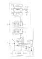
図2に示すように、一次側コイル13は、誘導コイルとしての一次コイル13aと、一次側共鳴コイル13bとで構成されている。一次コイル13aは、整合器12を介して高周波電源11に接続されている。一次コイル13aと一次側共鳴コイル13bとは同軸上に位置するように配設され、一次側共鳴コイル13bにはコンデンサCが接続されている。一次コイル13aは、一次側共鳴コイル13bに電磁誘導で結合され、高周波電源11から一次コイル13aに供給された交流電力が電磁誘導で一次側共鳴コイル13bに供給される。
As shown in FIG. 2, the primary coil 13 is composed of a primary coil 13a as an induction coil and a primary resonance coil 13b. The primary coil 13a is connected to the high frequency power supply 11 via the matching unit 12. The primary coil 13a and the primary side resonance coil 13b are disposed so as to be coaxially connected, and a capacitor C is connected to the primary side resonance coil 13b. The primary coil 13a is coupled to the primary side resonance coil 13b by electromagnetic induction, and AC power supplied from the high frequency power supply 11 to the primary coil 13a is supplied to the primary side resonance coil 13b by electromagnetic induction.
図2に示すように、整合器12は、2つの可変コンデンサ16,17とインダクタ18とから構成されている。一方の可変コンデンサ16は高周波電源11に接続され、他方の可変コンデンサ17は一次コイル13aに並列に接続されている。インダクタ18は両可変コンデンサ16,17間に接続されている。整合器12は、可変コンデンサ16,17の容量が変更されることでそのインピーダンスが変更される。
As shown in FIG. 2, the matching unit 12 includes two variable capacitors 16 and 17 and an inductor 18. One variable capacitor 16 is connected to the high frequency power supply 11, and the other variable capacitor 17 is connected in parallel to the primary coil 13a. The inductor 18 is connected between the variable capacitors 16 and 17. The impedance of the matching unit 12 is changed by changing the capacitance of the variable capacitors 16 and 17.
インピーダンス測定手段14は一次側コイル13の一次コイル13aに接続され、その測定結果が電源側コントローラ15に出力される。電源側コントローラ15は、インピーダンス測定手段14の測定結果に基づいて整合器12を共鳴系の入力インピーダンスと、共鳴系の入力端から高周波電源11側をみたインピーダンスとの整合を行うように調整する。共鳴系の入力端から高周波電源11側をみたインピーダンスとは、言い換えると本実施の形態では、電源部(高周波電源11)から共鳴系の入力端までのインピーダンスである。電源側コントローラ15は整合器制御手段(整合器制御部)としても機能する。
The impedance measuring means 14 is connected to the primary coil 13 a of the primary side coil 13, and the measurement result is output to the power supply side controller 15. The power supply controller 15 adjusts the matching unit 12 based on the measurement result of the impedance measuring means 14 so as to match the input impedance of the resonance system with the impedance viewed from the input end of the resonance system to the high frequency power supply 11 side. In other words, the impedance viewed from the resonance system input end toward the high frequency power supply 11 is the impedance from the power supply unit (high frequency power supply 11) to the resonance system input end. The power supply side controller 15 also functions as a matching unit control means (matching unit control unit).
二次側コイル31は、誘導コイルとしての二次コイル31aと二次側共鳴コイル31bとで構成されている。二次コイル31aと二次側共鳴コイル31bとは同軸上に位置するように配設され、二次側共鳴コイル31bにはコンデンサCが接続されている。二次コイル31aは、二次側共鳴コイル31bに電磁誘導で結合され、共鳴により一次側共鳴コイル13bから二次側共鳴コイル31bに供給された交流電力が電磁誘導で二次コイル31aに供給される。二次コイル31aは、整流器32に接続されている。この実施形態では、一次側共鳴コイル13b及び二次側共鳴コイル31bは同じに形成され、各コンデンサCとして同じ容量値のコンデンサが使用されている。
The secondary coil 31 includes a secondary coil 31a as an induction coil and a secondary resonance coil 31b. The secondary coil 31a and the secondary resonance coil 31b are disposed so as to be coaxially connected, and a capacitor C is connected to the secondary resonance coil 31b. The secondary coil 31a is coupled to the secondary side resonance coil 31b by electromagnetic induction, and AC power supplied from the primary side resonance coil 13b to the secondary side resonance coil 31b by resonance is supplied to the secondary coil 31a by electromagnetic induction. The The secondary coil 31 a is connected to the rectifier 32. In this embodiment, the primary resonance coil 13b and the secondary resonance coil 31b are formed in the same manner, and capacitors having the same capacitance value are used as the capacitors C.
高周波電源11は、その出力周波数foが、電波法で使用が許容されている条件を満たす。また、出力周波数foが、f1≦fo≦f2,f3≦fo≦f4,・・・,f2n-1≦fo≦f2nの範囲のいずれかに存在するように設定されている。
RF power supply 11, the output frequency f o is, satisfy the condition used in the Radio Law is allowed. Further, the output frequency f o is, f 1 ≦ f o ≦ f 2, f 3 ≦ f o ≦ f 4, ···, to be present in any of the range of f 2n-1 ≦ f o ≦ f 2n Is set.
次に前記のように構成された共鳴型非接触充電システムの設計方法を説明する。
Next, a design method for the resonance type non-contact charging system configured as described above will be described.
この設計方法は、共鳴系に異なる周波数f1,f2,f3,・・・,fn(f1<f2<f3<・・・<f2n-1<f2n)の電力を供給した時における共鳴系の入力インピーダンスをZ1,Z2,Z3,・・・,Z2n-1,Z2nとしたとき、Z1=Z2,Z3=Z4,・・・,Z2n-1=Z2nとなる周波数が存在する。そして、このとき共鳴系の共鳴周波数fo1,fo2,fo3,・・・,fonは、f1≦fo1≦f2,f3≦fo2≦f4,・・・,f2n-1≦fon≦f2nの範囲に存在するという本願発明者の知見に基づいていなされている。なお、インピーダンスをZi=Ri+jXiとすると、Z1=Z2とは、R1=R2かつX1=X2である。
In this design method, power of different frequencies f 1 , f 2 , f 3 ,..., F n (f 1 <f 2 <f 3 <... <f 2n−1 <f 2n ) is applied to the resonance system. When the input impedances of the resonance system when supplied are Z 1 , Z 2 , Z 3 ,..., Z 2n−1 , Z 2n , Z 1 = Z 2 , Z 3 = Z 4 ,. There is a frequency where Z 2n-1 = Z 2n . At this time the resonant system of the resonant frequency f o1, f o2, f o3 , ···, f on the, f 1 ≦ f o1 ≦ f 2, f 3 ≦ f o2 ≦ f 4, ···, f 2n This is based on the knowledge of the present inventor that it exists in the range of −1 ≦ f on ≦ f 2n . If the impedance is Z i = R i + jXi, Z 1 = Z 2 is R 1 = R 2 and X 1 = X 2 .
共鳴型非接触充電システムを設計する際には、共鳴系の構成部品となる整合器12、一次側コイル13、二次側コイル31及び負荷(整流器32、充電器33及びバッテリ34)の仕様の概要を決める。次に共鳴系を組み立て、その共鳴系に電波法で使用が許容されている条件を満たす周波数の出力を行う電源部から、異なる周波数で電力を供給し、そのときの共鳴系の入力インピーダンスを測定する。入力インピーダンスの測定には、例えば、電力測定器と位相測定器が使用される。そして、測定結果に基づいて入力インピーダンスが同じになる電源部の周波数の組があるかを調べる。測定した周波数範囲内に入力インピーダンスが同じとなる2つの周波数(例えば、f1,f2)の組が存在すれば、共鳴系の共鳴周波数はf1,f2の間に存在することになる。測定した周波数範囲内に入力インピーダンスが同じとなる周波数の組が存在しなければ、電源部の出力周波数の間隔を狭めたり、測定する周波数範囲を広げたりして再測定する。次に電源部の出力を周波数f1~f2の範囲で変化させて各周波数における電力伝送効率を測定する。測定結果から電力伝送効率が最大となる周波数が共鳴系の共鳴周波数となる。その結果に基づいて使用する電源部の出力周波数と共鳴系の共鳴周波数とが同じ値になるように共鳴系が設計される。なお、測定した周波数範囲内に入力インピーダンスが同じとなる周波数の組が複数組存在する場合もある。そのような場合には、例えば、最も低い周波数の組の周波数範囲内の電力伝送効率が最大となる周波数を特定し、その結果に基づいて共鳴系の設計を行う。
When designing a resonance type non-contact charging system, the specifications of the matching unit 12, the primary side coil 13, the secondary side coil 31, and the load (rectifier 32, charger 33, and battery 34) that are components of the resonance system are used. Decide on an overview. Next, assemble a resonance system, supply power at a different frequency from the power supply that outputs the frequency that satisfies the conditions permitted for use in the radio law, and measure the input impedance of the resonance system at that time. To do. For example, a power measuring device and a phase measuring device are used for measuring the input impedance. Then, based on the measurement result, it is examined whether there is a set of frequencies of the power supply unit having the same input impedance. If a set of two frequencies (for example, f 1 and f 2 ) having the same input impedance exists within the measured frequency range, the resonance frequency of the resonance system exists between f 1 and f 2. . If there is no set of frequencies having the same input impedance within the measured frequency range, the measurement is performed again by narrowing the output frequency interval of the power supply unit or expanding the frequency range to be measured. Next, the power transmission efficiency at each frequency is measured by changing the output of the power source in the range of frequencies f 1 to f 2 . From the measurement result, the frequency at which the power transmission efficiency is maximized is the resonance frequency of the resonance system. Based on the result, the resonance system is designed so that the output frequency of the power supply unit used and the resonance frequency of the resonance system have the same value. There may be a plurality of sets of frequencies having the same input impedance within the measured frequency range. In such a case, for example, the frequency that maximizes the power transmission efficiency within the frequency range of the lowest frequency set is specified, and the resonance system is designed based on the result.
この実施形態では、共鳴型非接触充電システムの設計、製造時に、先ず電源部(高周波電源11)を設定し、その電源部から出力される出力周波数に共鳴系の共鳴周波数が合うように、共鳴系の構成部品の仕様を設定する。そのため、電源部として出力周波数を広い範囲で出力可能な構成や、出力周波数の増減量の微調整機能を備えていない構成を採用でき、電源部が安価になる。
In this embodiment, at the time of designing and manufacturing a resonance type non-contact charging system, first, a power supply unit (high frequency power supply 11) is set, and the resonance frequency of the resonance system matches the output frequency output from the power supply unit. Set the specifications of system components. For this reason, a configuration capable of outputting the output frequency in a wide range as the power supply unit or a configuration not equipped with a fine adjustment function of the increase / decrease amount of the output frequency can be adopted, and the power supply unit becomes inexpensive.
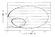
出力インピーダンスが50Ωで固定されている一般の高周波電源を使用して、出力周波数を9.50MHz~11.00MHzの範囲で変更して共鳴系の入力インピーダンスを測定した場合の入力インピーダンスの実部と虚部との関係を図3に示す。出力周波数は、9.50MHzから0.025MHzずつ増加するように変更して行った。なお、図3において、Psで示す点が出力周波数9.50MHzに対応する点で、Peで示す点が出力周波数11.00MHzに対応する点である。
The actual part of the input impedance when the input impedance of the resonance system is measured by changing the output frequency in the range of 9.50 MHz to 11.00 MHz using a general high-frequency power source whose output impedance is fixed at 50Ω. The relationship with the imaginary part is shown in FIG. The output frequency was changed from 9.50 MHz to 0.025 MHz. In FIG. 3, a point indicated by Ps corresponds to an output frequency of 9.50 MHz, and a point indicated by Pe corresponds to an output frequency of 11.00 MHz.
図3に示すように、共鳴系の入力インピーダンスは高周波電源の出力周波数の増加に対応して単純に変化するのではなく、周波数が9.50MHz~10.10MHzでは周波
数の増加に伴って入力インピーダンスの実部及び虚部とも増加し、その後、周波数10.18MHzまでは周波数の増加に伴って入力インピーダンスの実部は増加し、虚部は減少した。また、周波数のさらなる増加に伴って入力インピーダンスの実部及び虚部とも減少する状態、実部は減少して虚部は増加する状態、実部及び虚部とも増加する状態、実部は増加して虚部は減少する状態、実部及び虚部とも減少する状態、実部は減少して虚部は増加する状態となるように変化した。 As shown in FIG. 3, the input impedance of the resonance system does not simply change in response to the increase in the output frequency of the high frequency power supply, but the input impedance increases with the frequency when the frequency is 9.50 MHz to 10.10 MHz. The real part and the imaginary part of the input impedance increased, and thereafter, the real part of the input impedance increased and the imaginary part decreased as the frequency increased up to a frequency of 10.18 MHz. As the frequency further increases, the real and imaginary parts of the input impedance decrease, the real part decreases and the imaginary part increases, the real and imaginary parts increase, and the real part increases. The imaginary part is reduced, the real part and the imaginary part are both reduced, and the real part is reduced and the imaginary part is increased.
数の増加に伴って入力インピーダンスの実部及び虚部とも増加し、その後、周波数10.18MHzまでは周波数の増加に伴って入力インピーダンスの実部は増加し、虚部は減少した。また、周波数のさらなる増加に伴って入力インピーダンスの実部及び虚部とも減少する状態、実部は減少して虚部は増加する状態、実部及び虚部とも増加する状態、実部は増加して虚部は減少する状態、実部及び虚部とも減少する状態、実部は減少して虚部は増加する状態となるように変化した。 As shown in FIG. 3, the input impedance of the resonance system does not simply change in response to the increase in the output frequency of the high frequency power supply, but the input impedance increases with the frequency when the frequency is 9.50 MHz to 10.10 MHz. The real part and the imaginary part of the input impedance increased, and thereafter, the real part of the input impedance increased and the imaginary part decreased as the frequency increased up to a frequency of 10.18 MHz. As the frequency further increases, the real and imaginary parts of the input impedance decrease, the real part decreases and the imaginary part increases, the real and imaginary parts increase, and the real part increases. The imaginary part is reduced, the real part and the imaginary part are both reduced, and the real part is reduced and the imaginary part is increased.
図3において、f1で示す点の入力インピーダンスZ1と、f2で示す点の入力インピーダンスZ2がほぼ等しい。
In FIG. 3, the input impedance Z 1 at the point indicated by f 1 is substantially equal to the input impedance Z 2 at the point indicated by f 2 .
f1=10.325MHz、Z1=46.7+j4.69
f2=10.925MHz、Z2=51.6+j4.85
実験ではデータを細かく採っていないため、厳密にはZ1=Z2となっていないが、高周波電源の出力周波数の増加量を0.025MHzより小さな間隔でデータを採れば、図3に示す曲線の交点に対応する周波数のうち小さい方の周波数がf1になり、大きい方の周波数がf2になり、f1とf2でZ1=Z2になると考えられる。 f 1 = 10.325 MHz, Z 1 = 46.7 + j4.69
f 2 = 10.925 MHz, Z 2 = 51.6 + j4.85
Strictly, Z 1 = Z 2 is not obtained because the data is not finely taken in the experiment. However, if the increase amount of the output frequency of the high frequency power supply is taken at intervals smaller than 0.025 MHz, the curve shown in FIG. frequency the smaller becomes f 1 of the frequency corresponding to the intersections, the frequency of the larger becomes f 2, is believed to be the Z 1 = Z 2 at f 1 and f 2.
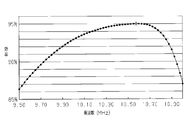
高周波電源の出力周波数を9.5MHz~11.0MHzの範囲で変化させて各周波数における電力伝送効率を測定した結果を図4に示す。図4から共鳴系における電力伝送効率が最大(95.05%)になる周波数10.575MHzが共鳴系の共鳴周波数foになる。この共鳴周波数fo(10.575MHz)は、f1(10.325MHz)とf2(10.925MHz)との間の値になり、f1≦fo≦f2の関係を満たす。
FIG. 4 shows the result of measuring the power transmission efficiency at each frequency by changing the output frequency of the high frequency power source in the range of 9.5 MHz to 11.0 MHz. From FIG. 4, the frequency of 10.575 MHz at which the power transmission efficiency in the resonance system is maximized (95.05%) is the resonance frequency fo of the resonance system. The resonance frequency f o (10.575 MHz) is a value between f 1 (10.325 MHz) and f 2 (10.925 MHz), and satisfies the relationship f 1 ≦ f o ≦ f 2 .
電力伝送効率が最大になる周波数がf1とf2との間以外に存在しないことを確認するため、高周波電源の出力周波数を9.5MHz~11.0MHzの範囲で変化させて各周波数における電力伝送効率を測定したが、電力伝送効率が最大になる周波数はf1とf2との間に存在することが確認された。したがって、共鳴周波数foの値は、高周波電源の出力周波数を周波数f1~f2の範囲で変化させて各周波数における電力伝送効率を測定することにより確認することができる。
Power in the presence to confirm that no, each by changing the output frequency of the high-frequency power in the range of 9.5MHz ~ 11.0MHz frequency other than between the frequency of the power transmission efficiency is maximized and f 1 and f 2 the transmission efficiency was measured, but the frequency of the power transmission efficiency is maximized, it was confirmed that exists between f 1 and f 2. Therefore, the value of the resonant frequency f o can be confirmed by measuring the power transmission efficiency at each frequency by the output frequency of the high-frequency power was varied in a range of frequencies f 1 ~ f 2.
次に前記のように構成された共鳴型非接触充電システムの作用を説明する。
Next, the operation of the resonance type non-contact charging system configured as described above will be described.
車両に搭載されたバッテリ34に充電を行う場合には、車両が給電設備10の近くの所定位置に停止した状態でバッテリ34への充電が行われる。電源側コントローラ15は、充電要求信号を入力すると、高周波電源11から一次コイル13aに共鳴系の共鳴周波数である出力周波数foで高周波電力を出力させる。なお、充電要求信号は車両側コントローラ35から出力されるか、給電設備10に設けられている図示しないスイッチを操作することにより出力される。
When charging the battery 34 mounted on the vehicle, the battery 34 is charged with the vehicle stopped at a predetermined position near the power supply facility 10. Power controller 15 inputs the charge request signal, the output frequency f o is the resonant frequency of the resonant system to the primary coil 13a from the high-frequency power source 11 to output a high frequency power. The charge request signal is output from the vehicle-side controller 35 or is operated by operating a switch (not shown) provided in the power supply facility 10.
そして、高周波電源11から一次コイル13aに共鳴系の共鳴周波数で高周波電力が出力され、電磁誘導により電力が供給された一次コイル13aに磁場が発生する。この磁場が一次側共鳴コイル13bと二次側共鳴コイル31bとによる磁場共鳴により増強される。増強された二次側共鳴コイル31b付近の磁場から二次コイル31aにより電磁誘導を利用して交流電力が取り出され、整流器32で整流された後、充電器33によりバッテリ34に充電される。
Then, high frequency power is output from the high frequency power supply 11 to the primary coil 13a at the resonance frequency of the resonance system, and a magnetic field is generated in the primary coil 13a to which power is supplied by electromagnetic induction. This magnetic field is enhanced by magnetic field resonance by the primary resonance coil 13b and the secondary resonance coil 31b. AC power is extracted from the magnetic field in the vicinity of the enhanced secondary resonance coil 31b by the secondary coil 31a using electromagnetic induction, rectified by the rectifier 32, and then charged to the battery 34 by the charger 33.
電源側コントローラ15は、インピーダンス測定手段14の検出信号を入力し、その検出信号に基づいて共鳴系の入力インピーダンスを確認し、共鳴系の入力インピーダンスと、共鳴系の入力端から高周波電源11側をみたインピーダンスとの整合を行うように、整合器12の調整を行う。
The power supply side controller 15 inputs the detection signal of the impedance measuring means 14, confirms the input impedance of the resonance system based on the detection signal, and connects the high frequency power supply 11 side from the resonance system input impedance and the input end of the resonance system. The matching unit 12 is adjusted so as to match with the observed impedance.
バッテリ34への充電時には、バッテリ34の充電状態が変化し、共鳴系の入力インピーダンスが変化する。
When charging the battery 34, the state of charge of the battery 34 changes and the input impedance of the resonance system changes.
しかし、充電中、電源側コントローラ15はインピーダンス測定手段14の検出信号に基づいて、共鳴系の入力インピーダンスを確認し、共鳴系の入力インピーダンスと、共鳴系の入力端から電源部(高周波電源11)側をみたインピーダンスとの整合を行うように整合器12を調整する。そのため、バッテリ34の充電状態が変化しても給電設備10から受電設備30へ電力が効率良く供給され、充電が効率良く行われる。
However, during charging, the power supply side controller 15 confirms the input impedance of the resonance system based on the detection signal of the impedance measuring means 14, and the power supply unit (the high frequency power supply 11) from the resonance system input impedance and the input terminal of the resonance system. The matching unit 12 is adjusted so as to match the impedance viewed from the side. Therefore, even if the charging state of the battery 34 changes, electric power is efficiently supplied from the power supply facility 10 to the power receiving facility 30, and charging is performed efficiently.
車両側コントローラ35は、バッテリ34が満充電になると、充電器33による充電を停止するとともに、電源側コントローラ15に充電終了信号を送信する。また、満充電に達する前であっても、例えば、運転者により充電停止指令が入力されると、充電器33による充電を停止するとともに、電源側コントローラ15に充電終了信号を送信する。電源側コントローラ15は、充電終了信号を受信すると電力伝送(給電)を終了する。
When the battery 34 is fully charged, the vehicle-side controller 35 stops charging by the charger 33 and transmits a charging end signal to the power-side controller 15. Even before full charge is reached, for example, when a charge stop command is input by the driver, charging by the charger 33 is stopped and a charge end signal is transmitted to the power supply side controller 15. The power supply side controller 15 will complete | finish electric power transmission (power feeding), if a charge completion signal is received.
この実施形態によれば、以下に示す効果を得ることができる。
According to this embodiment, the following effects can be obtained.
(1)共鳴型非接触充電システムは、高周波電源11と、高周波電源11から電力の供給を受ける一次側共鳴コイル13bとを備えた給電設備10と、一次側共鳴コイル13bからの電力を磁場共鳴して受電する二次側共鳴コイル31bと、二次側共鳴コイル31bが受電した電力が供給される負荷とを備えた受電設備30とを備えている。給電設備10には、高周波電源11から供給を受けた電力を電磁誘導により一次側共鳴コイル13bに供給する誘導コイル(一次コイル13a)が設けられており、少なくとも一次コイル13a、一次側共鳴コイル13b、二次側共鳴コイル31b及び負荷により共鳴系が構成される。そして、電源部(高周波電源11)の出力周波数foが、周波数f1≦fo≦周波数f2,周波数f3≦fo≦周波数f4,・・・,周波数f2n-1≦fo≦周波数f2nの範囲のいずれかに設定されている。周波数f1,f2,f3,f4,・・・,f2n-1,f2n(f1<f2<f3<・・・<f2n-1<f2n)は、共鳴系に前記周波数の電力を供給した時における共鳴系の入力インピーダンスをZ1,Z2,Z3,・・・,Z2n-1,Z2nとしたとき、Z1=Z2,Z3=Z4,・・・,Z2n-1=Z2nとなる周波数である。したがって、設計、製造が容易で、電力伝送効率を高くすることができる。そして、出力周波数foが、共鳴系の共鳴周波数に設定されていれば、電力の伝送効率が最大になる。
(1) The resonance-type non-contact charging system uses a high-frequency power source 11, a power supply facility 10 including a primary-side resonance coil 13 b that receives power supply from the high-frequency power source 11, and magnetic resonance of power from the primary-side resonance coil 13 b. Power receiving equipment 30 including a secondary resonance coil 31b that receives power and a load to which the power received by the secondary resonance coil 31b is supplied. The power supply facility 10 is provided with an induction coil (primary coil 13a) that supplies electric power supplied from the high-frequency power source 11 to the primary resonance coil 13b by electromagnetic induction. At least the primary coil 13a and the primary resonance coil 13b are provided. The secondary resonance coil 31b and the load constitute a resonance system. Then, the output frequency f o of the power supply unit (high-frequency power source 11), the frequency f 1 ≦ f o ≦ frequency f 2, the frequency f 3 ≦ f o ≦ frequency f 4, · · ·, the frequency f 2n-1 ≦ f o ≦ Set to one of the ranges of the frequency f 2 n. The frequencies f 1 , f 2 , f 3 , f 4 ,..., F 2n−1 , f 2n (f 1 <f 2 <f 3 <... <f 2n−1 <f 2n ) Z 1 = Z 2 , Z 3 = Z, where Z 1 , Z 2 , Z 3 ,..., Z 2n−1 , Z 2n are input impedances of the resonance system when power of the frequency is supplied to 4 ,..., Z 2n-1 = Z 2n . Therefore, design and manufacture are easy, and power transmission efficiency can be increased. The output frequency f o is, if it is set to the resonant frequency of the resonant system, the power transmission efficiency is maximized.
(2)共鳴型非接触充電システムの設計において、システムを構成する電源部(例えば高周波電源)の出力周波数を共鳴系の共鳴周波数に設定する場合、共鳴系の構成部品の仕様の概要を決める。次に共鳴系を組み立て、その共鳴系に電波法で使用が許容されている条件を満たす周波数の出力を行う電源部から、異なる周波数で電力を供給し、そのときの共鳴系の入力インピーダンスを測定する。測定結果に基づいて入力インピーダンスが同じになる電源部の周波数を調べ、異なる周波数f1,f2における入力インピーダンスZ1,Z2が同じになる組み合わせを見出す。そして、その周波数f1~f2の範囲で電力伝送効率が最大になる周波数が共鳴系の共鳴周波数となる。したがって、共鳴系の共鳴周波数の設定が容易になる。
(2) In designing a resonance type non-contact charging system, when setting the output frequency of a power supply unit (for example, a high frequency power supply) constituting the system to the resonance frequency of the resonance system, an outline of the specifications of the resonance system component parts is determined. Next, assemble a resonance system, supply power at a different frequency from the power supply that outputs the frequency that satisfies the conditions permitted for use in the radio law, and measure the input impedance of the resonance system at that time. To do. Measurement results based on examining the frequency of the power supply unit in which the input impedance is the same, finding different combinations frequencies f 1, the input impedance Z 1 in f 2, Z 2 are the same. The frequency at which the power transmission efficiency is maximized in the range of the frequencies f 1 to f 2 is the resonance frequency of the resonance system. Therefore, the resonance frequency of the resonance system can be easily set.
(3)共鳴型非接触充電システムは、給電設備10に高周波電源11から供給を受けた電力を電磁誘導により一次側共鳴コイル13bに供給する誘導コイル(一次コイル13a)が設けられ、受電設備30に磁場共鳴により一次側共鳴コイル13bから二次側共鳴コイル31bに供給された交流電力が電磁誘導で供給される誘導コイル(二次コイル31a)が設けられている。したがって、誘導コイルとして一次コイル13aあるいは二次コイル31aの一方のみ備えた構成に比べて、整合状態に調整するのが容易となる。
(3) The resonance type non-contact charging system is provided with an induction coil (primary coil 13a) that supplies power supplied from the high frequency power source 11 to the power supply facility 10 to the primary resonance coil 13b by electromagnetic induction. In addition, an induction coil (secondary coil 31a) is provided in which AC power supplied from the primary resonance coil 13b to the secondary resonance coil 31b by magnetic field resonance is supplied by electromagnetic induction. Therefore, it becomes easier to adjust the alignment state as compared with the configuration in which only one of the primary coil 13a or the secondary coil 31a is provided as the induction coil.
(4)給電設備10は、共鳴系の入力インピーダンスと共鳴系の入力端から電源部(高周波電源11)側をみたインピーダンスとの整合を行う整合器12と、整合器12を調整する整合器制御手段とを備えている。したがって、共鳴系の入力インピーダンスが変化しても電力の伝送効率を良好な状態に維持することができる。また、受電設備30の情報を入手せずに給電設備10で負荷の変化に対応することができる。
(4) The power supply facility 10 includes a matching unit 12 that performs matching between an input impedance of the resonance system and an impedance viewed from the input end of the resonance system to the power supply unit (high-frequency power source 11), and a matching unit control that adjusts the matching unit 12. Means. Therefore, even if the input impedance of the resonance system changes, the power transmission efficiency can be maintained in a good state. In addition, the power supply facility 10 can cope with a change in load without obtaining information on the power receiving facility 30.
(第2の実施形態)
次に、本発明を具体化した第2の実施形態を図5~図7にしたがって説明する。この実施形態では、共鳴系を構成するコイルの数が給電設備10及び受電設備30とも一つである点が前記第1の実施形態と異なっている。第1の実施形態と同一部分は同一符号を付して詳しい説明を省略する。 (Second Embodiment)
Next, a second embodiment embodying the present invention will be described with reference to FIGS. This embodiment is different from the first embodiment in that the number of coils constituting the resonance system is one for both thepower feeding facility 10 and the power receiving facility 30. The same parts as those in the first embodiment are denoted by the same reference numerals, and detailed description thereof is omitted.
次に、本発明を具体化した第2の実施形態を図5~図7にしたがって説明する。この実施形態では、共鳴系を構成するコイルの数が給電設備10及び受電設備30とも一つである点が前記第1の実施形態と異なっている。第1の実施形態と同一部分は同一符号を付して詳しい説明を省略する。 (Second Embodiment)
Next, a second embodiment embodying the present invention will be described with reference to FIGS. This embodiment is different from the first embodiment in that the number of coils constituting the resonance system is one for both the
図5に示すように、一次側共鳴コイル13bは、整合器12を介して高周波電源11に接続されている。二次側共鳴コイル31bは、整流器32に接続されている。即ち、一次側コイル13は、誘導コイルとしての一次コイル13aを備えずに一次側共鳴コイル13bのみで構成され、二次側コイル31は、誘導コイルとしての二次コイル31aを備えずに二次側共鳴コイル31bのみで構成されている。
As shown in FIG. 5, the primary resonance coil 13 b is connected to the high frequency power supply 11 through the matching unit 12. The secondary resonance coil 31 b is connected to the rectifier 32. That is, the primary side coil 13 is configured by only the primary side resonance coil 13b without including the primary coil 13a as the induction coil, and the secondary side coil 31 is not provided with the secondary coil 31a as the induction coil. It is comprised only by the side resonance coil 31b.
この実施形態においては、車両に搭載されたバッテリ34に充電を行う場合には、高周波電源11から一次側共鳴コイルに共鳴系の共鳴周波数で高周波電力が出力され、一次側共鳴コイル13bと二次側共鳴コイル31bとによる磁場共鳴により増強される。そして、二次側共鳴コイル31bから出力される交流電力が整流器32で整流された後、充電器33によりバッテリ34に充電される。
In this embodiment, when charging the battery 34 mounted on the vehicle, high-frequency power is output from the high-frequency power source 11 to the primary-side resonance coil at the resonance frequency of the resonance system, and the primary-side resonance coil 13b and the secondary-side resonance coil 13b. The magnetic resonance is enhanced by the side resonance coil 31b. The AC power output from the secondary resonance coil 31 b is rectified by the rectifier 32 and then charged to the battery 34 by the charger 33.
共鳴系を構成するコイルの数が一次側及び二次側とも一つの場合でも、第1の実施形態の場合と同様な方法で共鳴系充電システムを設計できることを確認するため、第1の実施形態における実施例1と同様な実験を行った。但し、高周波電源の出力周波数の範囲が第1の実施形態の場合の実施例1より低い周波数範囲で行った。出力周波数を50kHz~200kHzの範囲で変更して共鳴系の入力インピーダンスを測定した場合の入力インピーダンスの実部と虚部との関係を図6に示す。出力周波数は、50kHzから1kHzずつ増加するように変更して行った。なお、図6において、Psで示す点が出力周波数50kHzに対応する点で、Peで示す点が出力周波数200kHzに対応する点である。
In order to confirm that the resonant charging system can be designed in the same manner as in the first embodiment even when the number of coils constituting the resonant system is one on both the primary side and the secondary side, the first embodiment The same experiment as in Example 1 was performed. However, the range of the output frequency of the high frequency power source was lower than that in Example 1 in the case of the first embodiment. FIG. 6 shows the relationship between the real part and the imaginary part of the input impedance when the output frequency is changed in the range of 50 kHz to 200 kHz and the input impedance of the resonance system is measured. The output frequency was changed from 50 kHz to increase by 1 kHz. In FIG. 6, a point indicated by Ps corresponds to an output frequency of 50 kHz, and a point indicated by Pe corresponds to an output frequency of 200 kHz.
図6に示すように、共鳴系の入力インピーダンスは高周波電源の出力周波数の増加に対応して単純に変化するのではなく、周波数が50kHz~114kHzでは周波数の増加に伴って入力インピーダンスの実部及び虚部とも増加し、その後、周波数121kHzまでは周波数の増加に伴って入力インピーダンスの実部は増加し、虚部は減少した。また、周波数のさらなる増加に伴って入力インピーダンスの実部及び虚部とも減少する状態、実部は減少して虚部は増加する状態、実部及び虚部とも増加する状態、実部は増加して虚部は減少する状態、実部及び虚部とも減少する状態、実部は減少して虚部は増加する状態となるように変化した。
As shown in FIG. 6, the input impedance of the resonance system does not simply change in response to an increase in the output frequency of the high-frequency power supply, but when the frequency is 50 kHz to 114 kHz, the real part of the input impedance and The imaginary part increased, and thereafter, up to a frequency of 121 kHz, the real part of the input impedance increased and the imaginary part decreased as the frequency increased. As the frequency further increases, the real and imaginary parts of the input impedance decrease, the real part decreases and the imaginary part increases, the real and imaginary parts increase, and the real part increases. The imaginary part is reduced, the real part and the imaginary part are both reduced, and the real part is reduced and the imaginary part is increased.
図6において、f1で示す点の入力インピーダンスZ1と、f2で示す点の入力インピーダンスZ2がほぼ等しい。
In FIG. 6, the input impedance Z 1 at the point indicated by f 1 is substantially equal to the input impedance Z 2 at the point indicated by f 2 .
f1=123kHz、Z1=168.57+j2.49
f2=171kHz、Z2=162.0+j4.12
実験ではデータを細かく採っていないため、厳密にはZ1=Z2となっていないが、高周波電源の出力周波数の増加量を1kHzより小さな間隔でデータを採れば、図6に示す曲線の交点に対応する周波数のうち小さい方の周波数がf1になり、大きい方の周波数がf2になり、f1とf2でZ1=Z2になると考えられる。 f 1 = 123 kHz, Z 1 = 168.57 + j2.49
f 2 = 171 kHz, Z 2 = 162.0 + j4.12
Strictly, Z 1 = Z 2 is not obtained because the data is not taken in detail in the experiment. However, if the increase in the output frequency of the high frequency power supply is taken at intervals smaller than 1 kHz, the intersection of the curves shown in FIG. The smaller frequency among the frequencies corresponding to is f 1 , the larger frequency is f 2 , and it is considered that Z 1 = Z 2 at f 1 and f 2 .
高周波電源の出力周波数を50kHz~200kHzの範囲で変化させて各周波数における電力伝送効率を測定した結果を図7に示す。図7から共鳴系における電力伝送効率が最大(98.80%)になる周波数140kHzが共鳴系の共鳴周波数foになる。この共鳴周波数fo(140kHz)は、f1(123kHz)とf2(171kHz)との間の値になり、f1≦fo≦f2の関係を満たす。
FIG. 7 shows the result of measuring the power transmission efficiency at each frequency by changing the output frequency of the high frequency power source in the range of 50 kHz to 200 kHz. Power transmission efficiency in the resonant system from FIG. 7 is the maximum frequency 140kHz become (98.80%) is the resonant frequency f o of the resonant system. The resonance frequency f o (140 kHz) is a value between f 1 (123 kHz) and f 2 (171 kHz), and satisfies the relationship f 1 ≦ f o ≦ f 2 .
電力伝送効率が最大になる周波数がf1とf2との間以外に存在しないことを確認するため、高周波電源の出力周波数を50kHz~200kHzの範囲で変化させて各周波数における電力伝送効率を測定したが、電力伝送効率が最大になる周波数はf1とf2との間に存在することが確認された。したがって、共鳴周波数foの値は、高周波電源の出力周波数を周波数f1~f2の範囲で変化させて各周波数における電力伝送効率を測定することにより確認することができる。
To ensure that the frequency at which the power transmission efficiency is maximized does not exist other than between f 1 and f 2, the output frequency of the high-frequency power is varied in a range of 50 kHz ~ 200kHz measures power transmission efficiency at each frequency However, it has been confirmed that the frequency at which the power transmission efficiency is maximized exists between f 1 and f 2 . Therefore, the value of the resonant frequency f o can be confirmed by measuring the power transmission efficiency at each frequency by the output frequency of the high-frequency power was varied in a range of frequencies f 1 ~ f 2.
この第2の実施形態においては、第1の実施形態の効果(1)、(2)及び(4)と基本的に同様の効果を得ることができる他に次の効果を得ることができる。
In the second embodiment, the following effects can be obtained in addition to the effects basically the same as the effects (1), (2), and (4) of the first embodiment.
(5)給電設備10及び受電設備30とも共鳴系を構成するコイルの数が一つのため、共鳴系の小型化を図ることができ、受電設備30を車両に搭載する際の搭載スペースの確保が容易になるとともに搭載位置の自由度が大きくなる。
(5) Since the number of coils constituting the resonance system is one for both the power supply facility 10 and the power reception facility 30, it is possible to reduce the size of the resonance system, and to secure a mounting space when the power reception facility 30 is mounted on a vehicle. It becomes easy and the degree of freedom of the mounting position increases.
実施形態は前記両実施形態に限定されるものではなく、例えば、次のように具体化してもよい。
Embodiments are not limited to the above-described embodiments, and may be embodied as follows, for example.
○ 高周波電源11の出力周波数foは共鳴系の共鳴周波数に限らず、共鳴型非接触給電システムとして所望の性能(電力伝送効率)を達成する範囲内で、共鳴周波数から多少ずれた値としてもよい。
○ output frequency f o of the high frequency power source 11 is not limited to the resonant frequency of the resonant system, to the extent to achieve the desired performance (power transmission efficiency) as resonance type non-contact power supply system, even if some deviation value from the resonant frequency Good.
○ 共鳴型非接触給電システムが、給電設備10と受電設備30との間で非接触給電を行うためには、一次コイル13a、一次側共鳴コイル13b、二次コイル31a及び二次側共鳴コイル31bの全てが必須ではなく、第2の実施形態のように誘導コイルとしての一次コイル13a及び二次コイル31aの両方を省略してもよい。また、誘導コイルとしての一次コイル13a及び二次コイル31aのいずれか一方を省略してもよい。しかし、一次コイル13a、一次側共鳴コイル13b、二次コイル31a及び二次側共鳴コイル31bの全てを備えた構成の方が、整合状態に調整するのが容易である。
In order for the resonance type non-contact power feeding system to perform non-contact power feeding between the power feeding facility 10 and the power receiving facility 30, the primary coil 13a, the primary side resonance coil 13b, the secondary coil 31a, and the secondary side resonance coil 31b Are not essential, and both the primary coil 13a and the secondary coil 31a as induction coils may be omitted as in the second embodiment. Moreover, you may abbreviate | omit any one of the primary coil 13a and the secondary coil 31a as an induction coil. However, the configuration including all of the primary coil 13a, the primary side resonance coil 13b, the secondary coil 31a, and the secondary side resonance coil 31b is easier to adjust to the matching state.
○ 電源部は高周波電源に限らず、例えば、商用電源から供給される交流電力の周波数を変換して出力するものであってもよい。
○ The power supply unit is not limited to a high-frequency power supply, and may be one that converts and outputs the frequency of AC power supplied from a commercial power supply, for example.
○ インピーダンス測定手段14は一次側コイル13の入力インピーダンスを測定する構成に限らず、整合器12の入力端のインピーダンスを測定する構成としてもよい。この場合は、整合器12は共鳴系の一部を構成する。したがって、整合器12は共鳴系のインピーダンスを調整することができ、整合器12を調整することにより、共鳴系のインピーダンスの変化が抑制される。
O The impedance measuring means 14 is not limited to the configuration for measuring the input impedance of the primary side coil 13, and may be configured to measure the impedance at the input end of the matching unit 12. In this case, the matching unit 12 constitutes a part of the resonance system. Therefore, the matching device 12 can adjust the impedance of the resonance system, and adjusting the matching device 12 suppresses a change in the impedance of the resonance system.
○ 共鳴型非接触充電システムは、インピーダンス測定手段14を備えていなくてもよい。その場合、共鳴型非接触充電システムの設計、製造時における共鳴系のインピーダンスの測定は、外付けの電力測定器及び位相測定器を用いて計測する。
○ The resonance-type non-contact charging system may not include the impedance measuring means 14. In that case, resonance type impedance measurement at the time of designing and manufacturing the resonance type non-contact charging system is performed using an external power measuring device and phase measuring device.
○ 電源部の出力周波数foは共鳴系の共鳴周波数ではなくても、周波数f2n-1≦fo≦周波数f2nの範囲にあればよい。電源部の出力周波数foが周波数f2n-1≦fo≦周波数f2nの範囲にあれば、それ以外の周波数よりも電力伝送効率が高くなる。
○ also the output frequency f o of the power supply unit is not a resonance frequency of the resonant system, it is sufficient in the range of frequencies f 2n-1 ≦ f o ≦ frequency f 2n. If the range of the output frequency f o is the frequency f 2n-1 ≦ f o ≦ frequency f 2n of the power supply unit, the power transmission efficiency is higher than other frequencies.
○ 充電器33と整流器32との間にDC/DCコンバータを設け、インピーダンス測定手段14の測定結果に基づいてDC/DCコンバータのデューティを制御してもよい。
A DC / DC converter may be provided between the charger 33 and the rectifier 32, and the duty of the DC / DC converter may be controlled based on the measurement result of the impedance measuring means 14.
○ 共鳴型非接触充電システムの設計、製造時に、共鳴系の構成部品を設定した後、共鳴系の共鳴周波数となる出力周波数を出力可能な電源部を設定するようにしてもよい。しかし、電源部を設定した後、その電源部から出力される出力周波数に共鳴系の共鳴周波数が合うように、共鳴系の構成部品の仕様を変えて共鳴系の周波数を調整した方が、電源部を安価にすることができる。
○ At the time of designing and manufacturing a resonance type non-contact charging system, after setting the resonance system components, a power supply unit that can output an output frequency that is the resonance frequency of the resonance system may be set. However, after setting the power supply unit, it is better to adjust the resonance system frequency by changing the specifications of the resonance system components so that the resonance frequency of the resonance system matches the output frequency output from the power supply unit. The part can be made inexpensive.
○ 受電設備30にも整合器を設けてもよい。例えば、二次コイル31aと整流器32との間に整合器を設け、車両側コントローラ35がその整合器の調整を行うようにしてもよい。第2の実施形態のように、共鳴系に設けられたコイルが一次側共鳴コイル13b及び二次側共鳴コイル31bの2つの場合は、給電設備10及び受電設備30の両方に整合器を設けることが好ましい。
○ A matching unit may also be provided in the power receiving facility 30. For example, a matching device may be provided between the secondary coil 31a and the rectifier 32, and the vehicle-side controller 35 may adjust the matching device. As in the second embodiment, in the case where the coils provided in the resonance system are two of the primary side resonance coil 13b and the secondary side resonance coil 31b, a matching unit is provided in both the power supply facility 10 and the power reception facility 30. Is preferred.
○ 整合器12を二次側(受電設備30側)にだけ設けてもよい。また、整合器12を一次側(給電設備10側)及び二次側(受電設備30側)のいずれにも設けない構成としてもよい。
○ Matching device 12 may be provided only on the secondary side (power receiving equipment 30 side). Moreover, it is good also as a structure which does not provide the matching device 12 in any of a primary side (power supply equipment 10 side) and a secondary side (power receiving equipment 30 side).
○ 整流器32は充電器33に内蔵されていてもよい。
○ The rectifier 32 may be built in the charger 33.
○ 充電器33を設けずに、二次側コイル31から出力される交流電流を整流器32で整流した後、バッテリ34に直接充電するようにしてもよい。
O Without providing the charger 33, the battery 34 may be directly charged after the AC current output from the secondary coil 31 is rectified by the rectifier 32.
○ 整合器12は、2つの可変コンデンサ16,17とインダクタ18を備えた構成に限らず、例えば、インダクタ18として可変インダクタを備えた構成や、可変インダクタと2つの非可変コンデンサとからなる構成としてもよい。
○ The matching unit 12 is not limited to the configuration including the two variable capacitors 16 and 17 and the inductor 18. For example, the matching unit 12 includes a variable inductor as the inductor 18 or a configuration including a variable inductor and two non-variable capacitors. Also good.
○ 整合器として可変でない構成の整合器を採用してもよい。
○ 整合器に代えて力率改善回路(PFC回路)を設けてもよい。この場合は、インピーダンス測定手段14に代えて位相差測定手段(位相差測定部)を設ける。 ○ A matching device with a non-variable configuration may be adopted as the matching device.
A power factor correction circuit (PFC circuit) may be provided instead of the matching unit. In this case, a phase difference measuring unit (phase difference measuring unit) is provided instead of theimpedance measuring unit 14.
○ 整合器に代えて力率改善回路(PFC回路)を設けてもよい。この場合は、インピーダンス測定手段14に代えて位相差測定手段(位相差測定部)を設ける。 ○ A matching device with a non-variable configuration may be adopted as the matching device.
A power factor correction circuit (PFC circuit) may be provided instead of the matching unit. In this case, a phase difference measuring unit (phase difference measuring unit) is provided instead of the
○ 移動体としての車両は運転者を必要とする車両に限らず無人搬送車でもよい。
○ The vehicle as a moving body is not limited to a vehicle that requires a driver, and may be an automated guided vehicle.
○ 共鳴型非接触充電システムは、車両に搭載されたバッテリ34に対して非接触充電を行うシステムに限らない。例えば、船舶や自走式のロボット等の移動体に装備されたバッテリ、あるいは携帯電話機や携帯用パソコン等の携帯用の電子機器に装備されたバッテリに対して非接触充電を行うシステムであってもよい。
○ The resonance-type contactless charging system is not limited to a system that performs contactless charging to the battery 34 mounted on the vehicle. For example, a system that performs non-contact charging on a battery mounted on a mobile body such as a ship or a self-propelled robot, or a battery mounted on a portable electronic device such as a mobile phone or a portable personal computer. Also good.
○ 共鳴型非接触給電システムは共鳴型非接触充電システムに限らず、ロボット等の移動体に装備された電気機器に対して電力を供給する装置に適用してもよい。
○ The resonance-type non-contact power supply system is not limited to the resonance-type non-contact charging system, and may be applied to a device that supplies electric power to an electric device equipped on a moving body such as a robot.
○ 共鳴型非接触給電システムは、動力源としては非接触電力伝送を受けずに通常の電力で駆動されるコンベア等の移送手段(移送部)により定められた作業位置に移動され、かつ定電力で駆動されるモータを負荷として備えた装置に受電設備30を装備した構成としてもよい。
○ Resonance-type non-contact power supply system is moved to a work position determined by transfer means (transfer unit) such as a conveyor driven by normal power without receiving non-contact power transmission as a power source, and constant power It is good also as a structure equipped with the power receiving equipment 30 in the apparatus provided with the motor driven by 1 as a load.
○ 一次コイル13a及び二次コイル31aの径は、一次側共鳴コイル13b及び二次側共鳴コイル31bの径と同じに形成されている構成に限らず、小さくても大きくてもよい。
○ The diameters of the primary coil 13a and the secondary coil 31a are not limited to the same configuration as the diameters of the primary resonance coil 13b and the secondary resonance coil 31b, and may be small or large.
○ 第2の実施形態において、一次側共鳴コイル13b及び二次側共鳴コイル31bは巻き数が複数のコイルに限らず、巻き数数が1巻きのコイルを使用してもよい。
In the second embodiment, the primary-side resonance coil 13b and the secondary-side resonance coil 31b are not limited to a plurality of turns, and a coil having a turn number of 1 may be used.
○ 一次側共鳴コイル13b及び二次側共鳴コイル31bに接続されたコンデンサCを省略してもよい。しかし、コンデンサCを接続した構成の方が、コンデンサCを省略した場合に比べて、共鳴周波数を下げることができる。また、共鳴周波数が同じであれば、コンデンサCを省略した場合に比べて、一次側共鳴コイル13b及び二次側共鳴コイル31bの小型化が可能になる。
○ Capacitor C connected to primary side resonance coil 13b and secondary side resonance coil 31b may be omitted. However, the configuration in which the capacitor C is connected can lower the resonance frequency compared to the case where the capacitor C is omitted. Further, if the resonance frequency is the same, the primary resonance coil 13b and the secondary resonance coil 31b can be downsized compared to the case where the capacitor C is omitted.
以下の技術的思想(発明)は前記実施形態から把握できる。
The following technical idea (invention) can be grasped from the embodiment.
(1)請求項4に記載の発明において、前記給電設備は、前記共鳴系の入力インピーダンスを測定するインピーダンス測定手段を備え、前記インピーダンス測定手段の測定結果に基づいて前記共鳴系の入力インピーダンスと、共鳴系の入力端から前記電源部側をみたインピーダンスとの整合を行うように前記整合器を調整する整合器制御手段を備えている。
(1) In the invention according to claim 4, the power supply facility includes an impedance measurement unit that measures an input impedance of the resonance system, and based on a measurement result of the impedance measurement unit, an input impedance of the resonance system; Matching device control means for adjusting the matching device so as to perform matching with the impedance viewed from the input end of the resonance system to the power supply unit side is provided.
(2)前記技術的思想(1)に記載の発明において、前記受電設備は前記負荷として整流器、充電器及びバッテリを備えている。
(2) In the invention described in the technical idea (1), the power receiving facility includes a rectifier, a charger, and a battery as the load.
(3)前記技術的思想(1)又は(2)に記載の発明において、前記受電設備は車両に装備されている。
(3) In the invention described in the technical idea (1) or (2), the power receiving equipment is provided in a vehicle.
(4)請求項1~請求項4及び前記技術的思想(1)~(3)のいずれか一項に記載の発明において、前記高周波電源の出力周波数は電波法で使用が許容されている条件を満たす。
(4) In the invention according to any one of claims 1 to 4 and the technical ideas (1) to (3), the output frequency of the high-frequency power supply is a condition that is allowed to be used by the Radio Law. Meet.
Claims (4)
- 電源部と、前記電源部から電力の供給を受ける一次側共鳴コイルとを備えた給電設備と、
前記一次側共鳴コイルからの電力を磁場共鳴して受電する二次側共鳴コイルと、前記二次側共鳴コイルが受電した電力が供給される負荷とを備えた受電設備とを備え、
少なくとも前記一次側共鳴コイル、前記二次側共鳴コイル及び前記負荷により共鳴系を構成する共鳴型非接触給電システムであって、
前記電源部の出力周波数foが、周波数f1≦fo≦周波数f2,周波数f3≦fo≦周波数f4,・・・,周波数f2n-1≦fo≦周波数f2nの範囲のいずれかに設定され、
前記周波数f1,f2,f3,f4,・・・,f2n-1,f2n(f1<f2<f3<・・・<f2n-1<f2n)は、前記共鳴系に前記周波数の電力を供給した時における前記共鳴系の入力インピーダンスをZ1,Z2,Z3,・・・,Z2n-1,Z2nとしたとき、Z1=Z2,Z3=Z4,・・・,Z2n-1=Z2nとなる周波数である共鳴型非接触給電システム。 A power supply facility comprising a power supply unit and a primary resonance coil that receives power from the power supply unit;
A power receiving facility comprising a secondary side resonance coil that receives power from the primary side resonance coil by magnetic field resonance, and a load to which the power received by the secondary side resonance coil is supplied,
A resonance-type non-contact power feeding system that forms a resonance system with at least the primary side resonance coil, the secondary side resonance coil, and the load,
Output frequency f o of the power supply unit, the frequency f 1 ≦ f o ≦ frequency f 2, the frequency f 3 ≦ f o ≦ frequency f 4, · · ·, the range of the frequency f 2n-1 ≦ f o ≦ frequency f 2n Is set to
The frequencies f 1 , f 2 , f 3 , f 4 ,..., F 2n−1 , f 2n (f 1 <f 2 <f 3 <... <f 2n−1 <f 2n ) Z 1 = Z 2 , Z 2 when Z 1 , Z 2 , Z 3 ,..., Z 2n−1 , Z 2n are input impedances of the resonance system when power of the frequency is supplied to the resonance system. 3 = Z 4 ,..., Z 2n−1 = resonance-type non-contact power feeding system having a frequency satisfying Z 2n . - 前記給電設備及び前記受電設備の少なくとも一方には、前記電源部から供給を受けた電力を電磁誘導により前記一次側共鳴コイルに供給する誘導コイルあるいは前記二次側共鳴コイルにより受電された電力を電磁誘導により取り出す誘導コイルが設けられ、少なくとも前記誘導コイル、前記一次側共鳴コイル、前記二次側共鳴コイル及び前記負荷により共鳴系が構成されている請求項1に記載の共鳴型非接触給電システム。 At least one of the power supply facility and the power receiving facility is configured to electromagnetically receive the power received from the power supply unit to the primary resonance coil by electromagnetic induction or the power received by the secondary resonance coil. The resonance type non-contact power feeding system according to claim 1, wherein an induction coil to be taken out by induction is provided, and a resonance system is configured by at least the induction coil, the primary side resonance coil, the secondary side resonance coil, and the load.
- 前記誘導コイルは、前記給電設備及び前記受電設備の両方にそれぞれ設けられている請求項2に記載の共鳴型非接触給電システム。 The resonance type non-contact power feeding system according to claim 2, wherein the induction coil is provided in both the power feeding facility and the power receiving facility.
- 前記給電設備は、前記共鳴系の入力インピーダンスと前記共鳴系の入力端から前記電源部側をみたインピーダンスとの整合を行う整合器と、前記整合器を調整する整合器制御手段とを備えている請求項1~請求項3のいずれか一項に記載の共鳴型非接触給電システム。 The power supply facility includes a matching unit that performs matching between an input impedance of the resonance system and an impedance viewed from the input end of the resonance system when viewed from the power supply unit side, and a matching unit control unit that adjusts the matching unit. The resonance-type non-contact power feeding system according to any one of claims 1 to 3.
Priority Applications (4)
| Application Number | Priority Date | Filing Date | Title |
|---|---|---|---|
| CN201280028769.3A CN103608997A (en) | 2011-06-17 | 2012-05-11 | Resonance-type non-contact power supply system |
| EP12800731.7A EP2722966A4 (en) | 2011-06-17 | 2012-05-11 | Resonance-type non-contact power supply system |
| US14/125,795 US9577715B2 (en) | 2011-06-17 | 2012-05-11 | Resonance-type non-contact power supply system |
| JP2013520476A JP5751327B2 (en) | 2011-06-17 | 2012-05-11 | Resonant contactless power supply system |
Applications Claiming Priority (2)
| Application Number | Priority Date | Filing Date | Title |
|---|---|---|---|
| JP2011135390 | 2011-06-17 | ||
| JP2011-135390 | 2011-06-17 |
Publications (1)
| Publication Number | Publication Date |
|---|---|
| WO2012172900A1 true WO2012172900A1 (en) | 2012-12-20 |
Family
ID=47356895
Family Applications (1)
| Application Number | Title | Priority Date | Filing Date |
|---|---|---|---|
| PCT/JP2012/062180 WO2012172900A1 (en) | 2011-06-17 | 2012-05-11 | Resonance-type non-contact power supply system |
Country Status (5)
| Country | Link |
|---|---|
| US (1) | US9577715B2 (en) |
| EP (1) | EP2722966A4 (en) |
| JP (1) | JP5751327B2 (en) |
| CN (1) | CN103608997A (en) |
| WO (1) | WO2012172900A1 (en) |
Cited By (2)
| Publication number | Priority date | Publication date | Assignee | Title |
|---|---|---|---|---|
| CN103414261A (en) * | 2013-09-06 | 2013-11-27 | 中国矿业大学(北京) | Variable-coupling coefficient magnetic resonance wireless power transmission system and method |
| EP3136542A4 (en) * | 2014-04-23 | 2017-07-05 | Panasonic Intellectual Property Management Co., Ltd. | Contactless power transmission device, contactless power reception device, and contactless power transmission system |
Families Citing this family (8)
| Publication number | Priority date | Publication date | Assignee | Title |
|---|---|---|---|---|
| WO2012172900A1 (en) | 2011-06-17 | 2012-12-20 | 株式会社 豊田自動織機 | Resonance-type non-contact power supply system |
| EP2722967A4 (en) * | 2011-06-17 | 2015-09-09 | Toyota Jidoshokki Kk | Resonance-type non-contact power supply system |
| US9246357B2 (en) * | 2011-12-07 | 2016-01-26 | Semiconductor Energy Laboratory Co., Ltd. | Contactless power feeding system |
| JP6200167B2 (en) * | 2013-02-27 | 2017-09-20 | デクセリアルズ株式会社 | Power receiving device, received power adjusting method, received power adjusting program, and semiconductor device |
| WO2014203346A1 (en) * | 2013-06-19 | 2014-12-24 | ルネサスエレクトロニクス株式会社 | Power transmission device, wireless power feeding system, and control method |
| US20160241159A1 (en) * | 2013-10-31 | 2016-08-18 | Mitsubishi Electric Engineering Company, Limited | Resonant type high frequency power supply device |
| JP6315382B2 (en) | 2013-12-19 | 2018-04-25 | パナソニックIpマネジメント株式会社 | Power transmission device, power reception device, and wireless power transmission system for wireless power transmission |
| CN109995150A (en) * | 2019-03-19 | 2019-07-09 | 华中科技大学 | Apart from wireless power transmission systems and its high frequency electric source in one kind |
Citations (3)
| Publication number | Priority date | Publication date | Assignee | Title |
|---|---|---|---|---|
| JP2005184526A (en) * | 2003-12-19 | 2005-07-07 | Ntt Docomo Inc | Antenna unit |
| JP2010041558A (en) * | 2008-08-07 | 2010-02-18 | Yokohama National Univ | Impedance matching device and method of impedance matching |
| JP2010114964A (en) * | 2008-11-04 | 2010-05-20 | Toyota Industries Corp | Non-contact power transmitter and method for designing the same |
Family Cites Families (13)
| Publication number | Priority date | Publication date | Assignee | Title |
|---|---|---|---|---|
| JP4192775B2 (en) | 2003-12-05 | 2008-12-10 | 株式会社ダイフク | Contactless power supply equipment |
| JP4328705B2 (en) * | 2004-02-27 | 2009-09-09 | 均 北吉 | RFID tag device |
| CN102983639B (en) | 2005-07-12 | 2016-01-27 | 麻省理工学院 | Wireless non-radiative energy transmits |
| WO2007086462A1 (en) | 2006-01-27 | 2007-08-02 | Brother Kogyo Kabushiki Kaisha | Display device |
| FR2920927B1 (en) | 2007-09-11 | 2011-05-06 | Commissariat Energie Atomique | AUTOMATIC RADIOFREQUENCY CIRCUIT IMPEDANCE ADAPTATION METHOD AND AUTOMATICALLY ADAPTABLE TRANSMISSION OR RECEPTION SYSTEM |
| JP4911148B2 (en) | 2008-09-02 | 2012-04-04 | ソニー株式会社 | Contactless power supply |
| US8461720B2 (en) * | 2008-09-27 | 2013-06-11 | Witricity Corporation | Wireless energy transfer using conducting surfaces to shape fields and reduce loss |
| JP4759610B2 (en) * | 2008-12-01 | 2011-08-31 | 株式会社豊田自動織機 | Non-contact power transmission device |
| CN102239622A (en) * | 2008-12-09 | 2011-11-09 | 株式会社丰田自动织机 | Non-contact power transmission apparatus and power transmission method using a non-contact power transmission apparatus |
| JP5585098B2 (en) * | 2009-03-06 | 2014-09-10 | 日産自動車株式会社 | Non-contact power supply apparatus and method |
| JP5459058B2 (en) * | 2009-11-09 | 2014-04-02 | 株式会社豊田自動織機 | Resonant contactless power transmission device |
| EP2722967A4 (en) * | 2011-06-17 | 2015-09-09 | Toyota Jidoshokki Kk | Resonance-type non-contact power supply system |
| WO2012172900A1 (en) | 2011-06-17 | 2012-12-20 | 株式会社 豊田自動織機 | Resonance-type non-contact power supply system |
-
2012
- 2012-05-11 WO PCT/JP2012/062180 patent/WO2012172900A1/en active Application Filing
- 2012-05-11 US US14/125,795 patent/US9577715B2/en not_active Expired - Fee Related
- 2012-05-11 EP EP12800731.7A patent/EP2722966A4/en not_active Withdrawn
- 2012-05-11 CN CN201280028769.3A patent/CN103608997A/en active Pending
- 2012-05-11 JP JP2013520476A patent/JP5751327B2/en not_active Expired - Fee Related
Patent Citations (3)
| Publication number | Priority date | Publication date | Assignee | Title |
|---|---|---|---|---|
| JP2005184526A (en) * | 2003-12-19 | 2005-07-07 | Ntt Docomo Inc | Antenna unit |
| JP2010041558A (en) * | 2008-08-07 | 2010-02-18 | Yokohama National Univ | Impedance matching device and method of impedance matching |
| JP2010114964A (en) * | 2008-11-04 | 2010-05-20 | Toyota Industries Corp | Non-contact power transmitter and method for designing the same |
Non-Patent Citations (2)
| Title |
|---|
| See also references of EP2722966A4 * |
| TAKEHIRO IMURA, HIROYUKI OKABE ET AL.: "Study of Magnetic and Electric Coupling for Contactless Power Transfer Using Equivalent Circuits", IEEJ TRANSACTIONS ON INDUSTRY APPLICATIONS, DENGAKURON D, vol. 130, no. 1, January 2010 (2010-01-01), pages 84 - 88, XP008172698 * |
Cited By (2)
| Publication number | Priority date | Publication date | Assignee | Title |
|---|---|---|---|---|
| CN103414261A (en) * | 2013-09-06 | 2013-11-27 | 中国矿业大学(北京) | Variable-coupling coefficient magnetic resonance wireless power transmission system and method |
| EP3136542A4 (en) * | 2014-04-23 | 2017-07-05 | Panasonic Intellectual Property Management Co., Ltd. | Contactless power transmission device, contactless power reception device, and contactless power transmission system |
Also Published As
| Publication number | Publication date |
|---|---|
| US20140175897A1 (en) | 2014-06-26 |
| EP2722966A1 (en) | 2014-04-23 |
| JP5751327B2 (en) | 2015-07-22 |
| CN103608997A (en) | 2014-02-26 |
| EP2722966A4 (en) | 2015-09-09 |
| US9577715B2 (en) | 2017-02-21 |
| JPWO2012172900A1 (en) | 2015-02-23 |
Similar Documents
| Publication | Publication Date | Title |
|---|---|---|
| JP5751327B2 (en) | Resonant contactless power supply system | |
| WO2012172899A1 (en) | Resonance-type non-contact power supply system | |
| US9287719B2 (en) | Power supply side equipment and resonance-type non-contact power supply system | |
| JP5457552B2 (en) | Resonant non-contact power feeding system and method for adjusting matching unit during charging of resonant non-contact power feeding system | |
| JP5459058B2 (en) | Resonant contactless power transmission device | |
| US9203475B2 (en) | Wireless power transmission system, wireless power receiving apparatus, and wireless power receiving method | |
| WO2011093292A1 (en) | Non-contact power transmission system and non-contact power transmission apparatus | |
| US20140103711A1 (en) | Contactless power receiving device, vehicle equipped with the same, contactless power transmitting device, and contactless power transfer system | |
| WO2013084754A1 (en) | Contactless power transmission device | |
| JP2012060807A (en) | Power supplying device, power receiving device and vehicle equipped with the same, and method of controlling power supplying system | |
| JP2011155733A (en) | Noncontact power transmission system and noncontact power transmission device | |
| WO2014002940A1 (en) | Non-contact power transmission device | |
| WO2017056343A1 (en) | Wireless power transmission system and power transmission device | |
| WO2013183700A1 (en) | Power reception device and contactless power transmission system | |
| WO2014007352A1 (en) | Transmitting device and non-contact power transmission device | |
| JP6535003B2 (en) | Wireless power receiver | |
| WO2015083578A1 (en) | Contactless power transmission device and electricity reception apparatus | |
| WO2014054395A1 (en) | Power transmission device, power reception device and noncontact power transfer apparatus | |
| JP5991380B2 (en) | Non-contact power transmission device | |
| KR20150055755A (en) | Hybrid wireless power transmission device which enables to transmit resonance power signal and induced power signal simultaneously and hybrid wireless power transmission system including the same | |
| JP2014197935A (en) | Power transmission system | |
| WO2015098747A1 (en) | Power transmission device and non-contact power transmission apparatus | |
| KR102086859B1 (en) | Hybrid type wireles power receiving device, method of controlling wireless power signal in hybrid type wireles power receiving device, and magnetic resonance type wireless power receiving device related to the same | |
| JP2012257374A (en) | Non-contact power transmission device | |
| WO2013183701A1 (en) | Power receiving apparatus, power transmitting apparatus, and non-contact power transmitting device |
Legal Events
| Date | Code | Title | Description |
|---|---|---|---|
| 121 | Ep: the epo has been informed by wipo that ep was designated in this application |
Ref document number: 12800731 Country of ref document: EP Kind code of ref document: A1 |
|
| ENP | Entry into the national phase |
Ref document number: 2013520476 Country of ref document: JP Kind code of ref document: A |
|
| NENP | Non-entry into the national phase |
Ref country code: DE |
|
| WWE | Wipo information: entry into national phase |
Ref document number: 14125795 Country of ref document: US |