WO2012172073A1 - Verfahren zur bereitstellung eines vorhersagemodells für eine rissdetektion und verfahren zur rissdetektion an einer halbleiterstruktur - Google Patents
Verfahren zur bereitstellung eines vorhersagemodells für eine rissdetektion und verfahren zur rissdetektion an einer halbleiterstruktur Download PDFInfo
- Publication number
- WO2012172073A1 WO2012172073A1 PCT/EP2012/061496 EP2012061496W WO2012172073A1 WO 2012172073 A1 WO2012172073 A1 WO 2012172073A1 EP 2012061496 W EP2012061496 W EP 2012061496W WO 2012172073 A1 WO2012172073 A1 WO 2012172073A1
- Authority
- WO
- WIPO (PCT)
- Prior art keywords
- crack
- semiconductor structure
- descriptor
- point
- measurement
- Prior art date
- Legal status (The legal status is an assumption and is not a legal conclusion. Google has not performed a legal analysis and makes no representation as to the accuracy of the status listed.)
- Ceased
Links
Classifications
-
- G—PHYSICS
- G01—MEASURING; TESTING
- G01N—INVESTIGATING OR ANALYSING MATERIALS BY DETERMINING THEIR CHEMICAL OR PHYSICAL PROPERTIES
- G01N21/00—Investigating or analysing materials by the use of optical means, i.e. using sub-millimetre waves, infrared, visible or ultraviolet light
- G01N21/62—Systems in which the material investigated is excited whereby it emits light or causes a change in wavelength of the incident light
- G01N21/63—Systems in which the material investigated is excited whereby it emits light or causes a change in wavelength of the incident light optically excited
- G01N21/64—Fluorescence; Phosphorescence
- G01N21/6489—Photoluminescence of semiconductors
-
- G—PHYSICS
- G01—MEASURING; TESTING
- G01N—INVESTIGATING OR ANALYSING MATERIALS BY DETERMINING THEIR CHEMICAL OR PHYSICAL PROPERTIES
- G01N21/00—Investigating or analysing materials by the use of optical means, i.e. using sub-millimetre waves, infrared, visible or ultraviolet light
- G01N21/84—Systems specially adapted for particular applications
- G01N21/88—Investigating the presence of flaws or contamination
- G01N21/93—Detection standards; Calibrating baseline adjustment, drift correction
-
- G—PHYSICS
- G01—MEASURING; TESTING
- G01N—INVESTIGATING OR ANALYSING MATERIALS BY DETERMINING THEIR CHEMICAL OR PHYSICAL PROPERTIES
- G01N21/00—Investigating or analysing materials by the use of optical means, i.e. using sub-millimetre waves, infrared, visible or ultraviolet light
- G01N21/84—Systems specially adapted for particular applications
- G01N21/88—Investigating the presence of flaws or contamination
- G01N21/95—Investigating the presence of flaws or contamination characterised by the material or shape of the object to be examined
- G01N21/9501—Semiconductor wafers
-
- G—PHYSICS
- G06—COMPUTING OR CALCULATING; COUNTING
- G06T—IMAGE DATA PROCESSING OR GENERATION, IN GENERAL
- G06T7/00—Image analysis
- G06T7/0002—Inspection of images, e.g. flaw detection
- G06T7/0004—Industrial image inspection
- G06T7/001—Industrial image inspection using an image reference approach
-
- H—ELECTRICITY
- H10—SEMICONDUCTOR DEVICES; ELECTRIC SOLID-STATE DEVICES NOT OTHERWISE PROVIDED FOR
- H10P—GENERIC PROCESSES OR APPARATUS FOR THE MANUFACTURE OR TREATMENT OF DEVICES COVERED BY CLASS H10
- H10P74/00—Testing or measuring during manufacture or treatment of wafers, substrates or devices
- H10P74/20—Testing or measuring during manufacture or treatment of wafers, substrates or devices characterised by the properties tested or measured, e.g. structural or electrical properties
- H10P74/203—Structural properties, e.g. testing or measuring thicknesses, line widths, warpage, bond strengths or physical defects
-
- G—PHYSICS
- G06—COMPUTING OR CALCULATING; COUNTING
- G06T—IMAGE DATA PROCESSING OR GENERATION, IN GENERAL
- G06T2207/00—Indexing scheme for image analysis or image enhancement
- G06T2207/10—Image acquisition modality
- G06T2207/10048—Infrared image
-
- G—PHYSICS
- G06—COMPUTING OR CALCULATING; COUNTING
- G06T—IMAGE DATA PROCESSING OR GENERATION, IN GENERAL
- G06T2207/00—Indexing scheme for image analysis or image enhancement
- G06T2207/20—Special algorithmic details
- G06T2207/20081—Training; Learning
-
- G—PHYSICS
- G06—COMPUTING OR CALCULATING; COUNTING
- G06T—IMAGE DATA PROCESSING OR GENERATION, IN GENERAL
- G06T2207/00—Indexing scheme for image analysis or image enhancement
- G06T2207/30—Subject of image; Context of image processing
- G06T2207/30108—Industrial image inspection
- G06T2207/30148—Semiconductor; IC; Wafer
Definitions
- the invention relates to a method for providing a predictive model for a crack detection on a semiconductor structure according to claim 1 and a method for crack detection on a semiconductor structure according to claim 2,
- the semiconductor structure is a photovoltaic solar cell, a precursor of a photovoltaic solar cell in the manufacturing process or in particular semiconductor material for Production of such a photovoltaic solar cell,
- Photovoltaic solar cells constructed of semiconductor material have long been used to convert electromagnetic radiation into electrical energy.
- the semiconductor material represents a significant proportion of the total costs for producing the solar cell. Therefore, more cost-effective materials, such as multicrystalline silicon, are increasingly used and, moreover, one objective of solar cell research is to increase the thickness of the semiconductor used. wafer in the production of the photovoltaic solar cell to reduce, thus reducing the cost of materials.
- Such cracks can arise, for example, due to material defects in a silicon ingot, due to burdens in the production of the wafer raw material, due to defects and mechanical stress during sawing of the wafers and due to mechanical stress during transport and handling.
- the semiconductor material is exposed to mechanical and thermal stresses in the manufacturing process. If the semiconductor material breaks down in the manufacturing process, high costs arise because, among other things, production must be stopped. But also such semiconductor material, which passes through the entire manufacturing process despite a crack, can lead to a considerable loss of performance when using the photovoltaic solar cell in later use.
- infrared transmitted light images It is known to detect cracks by means of so-called infrared transmitted light images.
- the semiconductor structure is subjected to transmitted light measurement by means of radiation in the infrared range and measured by means of an imaging method, such as a CCD camera. Due to the different absorption in the I R region, a user can see cracks with the eye in the image thus obtained.
- the crack detection by means of photoluminescence is known:
- photoluminescent radiation is generated in the semi-fairlead structure and measured by means of an imaging method, such as a CCD camera with spatial resolution.
- the application of photoluminescence measurements is basically known and described, for example, in Trupke, T. Progress with luminescence imaging for the characterization of silicon wafers and solar cells. in Proceedings of the 22nd European Photovoltaic Solar Energy Conference. 2007. Milan, Italy.
- the invention is based on the object, a reliable and in particular industrially applicable method for crack detection in a semiconductor structure, which is a photovoltaic solar cell, a precursor in Hersgnacsrata a photovoltaic solar cell or raw material for the production of the photovoltaic solar cell is to provide
- the invention is based on the Applicant's finding that learning algorithms are suitable for creating a predictive model for crack detection on a semiconductor structure, so that crack detection takes place on the basis of the predictive model.
- the method according to the invention and the device according to the invention therefore fundamentally differ from the methods for crack detection hitherto used in the photovoltaic field, since for the first time machine learning by means of a learning algorithm for crack detection is used.
- the methods and apparatus of the invention for crack detection relate to the photovoltaic region.
- semiconductor structure is used herein and hereinafter to refer to raw material such as silicon wafers and in particular multicrystalline silicon wafers for producing a solar cell, as well as the precursor of a photovoltaic solar cell at any point in the manufacturing price and the finished solar cell.
- the inventive method for providing a predictive model for a crack detection on a semiconductor structure comprises the following method steps;
- a reference semiconductor structure which reference semiconductor structure has at least one crack.
- crack data are provided for the at least one crack.
- the crack data comprise geometric location data with respect to the position of the crack on the reference semiconductor structure.
- the semiconductor structure typically represents a planar element, so that the crack typically with respect to the position of the front or Rear side of the semiconductor structure can be described, that is typically by means of two-dimensional geometric data.
- the crack data comprise a multiplicity of points and / or lines which describe the extent of the crack, and / or that the crack data comprise a crack center at which at least two lines of a star-shaped crack intersect.
- the reference hatch structure prefferably be a semiconductor structure which has a crack, which crack was measured by means of a further measurement method with regard to the geometric position.
- a spatially resolved measurement of the reference semiconductor structure takes place.
- a spatially resolved measurement of photoluminescence radiation generated in the semiconductor structure and / or spatially resolved measurement of the infrared absorption (IR absorption) of the semiconductor structure is carried out for a plurality of local measurement points.
- imaging methods known measuring apparatuses and in particular CCD cameras for spatially resolved surveying can be used. It is essential that a spatially resolved survey for a variety of local measurement points takes place.
- the measuring points cover at least a region on the surface of the semiconductor structure which comprises the crack.
- a learning algorithm is trained on the basis of the spatially resolved measurement data determined in method step C and the crack data provided in method step B.
- a physical model is not used in order to distinguish those measuring points, which are assigned to a crack, from the other measuring points on the basis of the measuring signals.
- the specifications and criteria ie the characteristics of these descriptions, which characterize the crack and differ with respect to the measurement signals from other elements, such as recombination-active geometric structures, are thus not predefined, but formed by training the learning algorithm.
- the training of the learning algorithm comprises the following method steps:
- a method step D1 at least one descriptor is created for at least one local descriptor point.
- a test region is specified or determined for the descriptor point, and based on the measurement data within the test region, the descriptor is created, which descriptor is a feature vector and / or a feature distribution and / or a feature histogram.
- test region thus comprises at least a subset of the measuring points from method step C. It is also within the scope of the invention that the test region comprises all measuring points from method step C.
- the descriptor point is a local point for which the named descriptor is formed, so that a description for the local descriptor point taking into account the test region is formed on the basis of the feature vector and / or the feature distribution and / or the feature histogram.
- the features of the feature vector and / or the feature distribution and / or the feature histogram are based on the measured data determined in method step C. It is within the scope of the invention that the features emerge directly from the measured data. In particular, however, it is advantageous for the features to be a further processing and / or correlation, in particular a structural description of a plurality of measured data.
- the learning algorithm is trained by means of the descriptor and the crack data
- the training can be carried out in a conventional manner with a learning algorithm known per se.
- a learning algorithm known per se.
- the training is carried out with a plurality of descriptor points and corresponding descriptors.
- the training of the learning algorithm can, as already described, take place in a manner known per se. What is important here is that it is known on the basis of the given crack data whether there is a crack at the descriptor point or not. This information is critical to the formation of a classification performed by the learning algorithm during training.
- each reference semiconductor structure it is not absolutely necessary for each reference semiconductor structure to have a crack, since for training also descriptor points and descriptors in which there is no crack make sense.
- at least one reference semiconductor structure must have at least one crack, as described above.
- the method according to the invention for crack detection on a semiconductor structure comprises the following method steps:
- a method step A the semiconductor structure is provided.
- a prediction model is provided.
- the prediction model was created by training a learning algorithm, preferably by means of a method according to claim 1 or an advantageous embodiment thereof,
- a spatially resolved measurement of the semiconductor structure is carried out by spatially resolved measurement for a plurality of local measurement points of photoluminescence radiation generated in the semiconductor structure and / or spatially resolved measurement of the I R absorption of the semiconductor structure.
- Method step C can therefore be identical to method step C according to claim 1 or an advantageous embodiment thereof.
- it is advantageous to carry out the same type of measurement ie in each case a spatially resolved measurement of photoluminescence radiation or in each case a spatially resolved measurement of the I R absorption in the generation of the predictive model and in the crack detection.
- the local test point represents a point on a surface of the semiconductor structure and preferably corresponds to one of the measurement points according to method step C.
- the determination comprises the following process steps:
- a method step D1 at least one descriptor for the checkpoint is created, in which a check region is specified and determined for the checkpoint and the descriptor creates the descriptor based on the measured data, which descriptor is a feature vector and / or a feature distribution and / or a Feature histogram is.
- Method step D1 in the crack detection is thus analogous to method step D1 in the preparation of the predictive model according to claim 1, wherein in claim 1, the descriptor for a corresponding descriptor point and in claim 2, the descriptor for a corresponding checkpoint is created. All previous and subsequent explanations of descriptor production can thus - at least by analogy - both with regard to Step D1 according to claim 1, as well as method step D1 according to claim 2 are used.
- a descriptor is created for the checkpoint, which thus represents features in the form of a feature vector and / or a feature distribution and / or a feature histogram, so that properties for the checkpoint are taken into account in step C of FIG obtained measurement data within the test region in the descriptor are mapped.
- the method according to the invention for crack detection is therefore distinguished by the fact that only one predictive model has to be made available, for example by carrying out a method according to claim 1, and then a measurement according to method step C is carried out in a manner known per se as photoluminescence measurement or measurement of I R absorption and, by creating a descriptor, it is possible to determine by means of the predictive model whether there is a crack at the checkpoint.
- step D2 it is within the scope of the invention to carry out the aforementioned determination according to method step D2 only at one test point.
- the determination is performed at a plurality of test points.
- successively each of the local measuring points at which a measurement takes place in method step C is selected as the test point.
- a learning algorithm can be trained by the manufacturer with high accuracy by exact preparation of a reference semiconductor structure and / or training on the basis of a multiplicity of cracks and crack data, and the prediction model designed in this way can be made available to the user. It is thus not absolutely necessary to also carry out a training of the learning algorithm on the user side.
- the user can also apply the manufacturer-trained predictive model directly to crack detection.
- a crack reconstruction takes place, in which the geometric data of the crack characteristic are determined.
- a reconstruction is carried out in order to determine at least the partial, preferably the complete geometric expression of a crack.
- a local reconstruction region around the checkpoint it is advantageous in method step E for a local reconstruction region around the checkpoint to have an orientation for each measurement point within the reconstruction region determine and determine the measurement points associated with the crack by means of a similarity comparison with a star-shaped and / or linear pattern by pattern recognition.
- the above-mentioned preferred embodiments are advantageous in particular when using photouminance measuring methods and in particular when using multicrystalline silicon semiconductor structures.
- This preferred embodiment of the method according to the invention is based on the Applicant's knowledge that cracks in semiconductor structures typically have a star-shaped pattern.
- a crack reconstruction can be carried out with a combination of methods known per se for the detection and reconstruction of a star-shaped and / or linear pattern.
- method step D it is within the scope of the invention in method step D when the predictive model is generated and / or during the crack detection.
- all the local measuring points measured in the respective method steps G may be used, for example, as successive determination of a multiplicity of loci as descriptor points or test points.
- the key points it is within the scope of the invention to determine the key points within the entire range, in particular starting from all measuring points. Likewise, it is within the scope of the invention to specify restricted geometric regions on the surface of the semiconductor structure and / or a subset of the measurement points measured in method step C, within which key points are determined.
- filters are Sobel, Prewitt, Gaussian, Difference-of-Gaussian, Laplacian-of-Gaussian.
- tensors such as Harris detector, determinant of Hessian in the invention or the use of controllable filters
- wavelets such as Gabor and Haarwavelets.
- the use of the SUSAN corner detector or the Canny edge detector is within the scope of the invention.
- the positive filter responses are correlated with different spatial orientation of the filter, preferably added up.
- the rotation group SO (2) As described, for example, in H. Schulz-Mirbach. Use of invariance principles for feature extraction in pattern recognition. Dissertation, Hamburg University of Technology, feb 1995. Series 10, No. 372, VDI-Verlag.
- the identification of key points has the advantage that the number of potential fracture regions can be limited to a significantly smaller set of key points, thus accelerating the process.
- the detection result of an I R measurement can be used in a conventional manner in order to determine key points.
- different measurement methods can be combined: For example, the determination of key points based on an I R measurement within the scope of the invention, whereupon a Photolumi- neszenzflop for the previously obtained by means of I R measurement key points for crack detection is evaluated.
- the descriptor in method step D1 according to claim 1 and / or claim 2 according to at least one of the methods SIFT, GLOH, HOG, LESH and / or SURF and / or a variant of these methods, in which a descriptor is generated based on the characteristics of a test region determined.
- a calibratable and rotatable filter preferably a bar filter as described above, is used to construct the descriptor.
- the LESH method is known per se and described for example in Sarfraz, S. , Hellwich, O .: "Head Pose Estimation in Face Recognition Across Pose Scenes rios ", Proceedings of VISAPP 2008, Inf. Conference on Computer Vision Theory and Applications, Madeira, Portugal, pp, 235-242, January 2008 (Best Student Paper Award).
- a method step D 1 .1 the determination of an amplitude and an orientation for each location point of the test region, for example for each measurement point within the test region, preferably by determining a characteristic for each measurement point of the test region, which characteristic more preferably the gradient of the measured value for the respective measuring point or the maximum filter response and orientation of a controllable filter for the respective measuring point.
- a feature histogram is generated for at least selected key points of the test region.
- a main crack orientation is determined and that a correction of the feature histogram is performed on the basis of the main crack orientation in order to obtain a rotationally invariant feature histogram.
- a description of the test region is thus made about the descriptor point or test point on the basis of features.
- This feature description can, for. B. consist of one or more features, a feature distribution or their characteristics or histograms of certain characteristics of these features.
- known feature descriptions according to the descriptors can be used under the known algorithms SIFT, G LOH, HOG, LESH or SURF.
- the basis for determining the descriptors are in each case the measured data ascertained in method step C.
- the main crack orientation is determined between method steps D1.1 and D1 .2, and in method step D1 .2 the feature histogram is generated by scanning the measuring points within the test region by means of a Sampling algorithm.
- a Sampling algorithm is particularly advantageous here.
- known per se sampling algorithms according to GLON and / or SI FT or variants thereof.
- a specific sampling and / or division of the image section can thus be used.
- known per se samples according to the aforementioned algorithms are applicable.
- pre- or post-process the feature description when creating the descriptors can be achieved by a correction of the descriptor according to the determined main orientation of the crack rotational invariance as described above. Furthermore, by scaling and / or smoothing the descriptor robustness against contrast changes or noise can be achieved.
- test region D1 is comprehensively determined by the following method steps:
- the measurement points within the test region are determined, in which a geometric extension and shape is specified for the test region.
- a geometric extension and shape is specified for the test region.
- a rectangular, elliptical or circular region whose center is the key point is specified for the test region.
- the geometric position of grain boundaries is predefined as grain boundary data within the semiconductor structure and / or determined by means of a spatially resolved measurement method, and a weighting is performed depending on the grain boundary data
- such location points which are located on a grain boundary, are not selected as a key point or are provided in determining the key point with respect to the other local points lower weighting and / or
- step D When creating a descriptor in step D in creating the prediction model and / or in the crack detection such location points that are not on a grain boundary or taken into account with a lower weighting compared to the other location points and / or
- This preferred embodiment is thus used in particular when applying the method according to the invention to multicrystalline silicon wafers. If the geometric position of the grain boundaries is previously known or can easily be determined on the basis of the available measuring apparatuses, the susceptibility to error in the crack detection can thus be further reduced by using the information about the position of the grain boundaries in the inventive method as described above.
- the learning algorithm used to create the predictive model or to carry out the crack detection can be a learning algorithm known per se.
- the use of a neural network, or a Bayes classifier or a kernel machine is within the scope of the invention.
- Applicant's investigations have shown that, in particular, the use of a support vector machine algorithm is advantageous. This is in it justified » that the support vector machine determines the optimal hyperplane for the separation of the feature descriptions of the classes" crack "and” no crack "to solve the classification task. This results in a considerable advantage, because the interface is optimally located between the classes. Feature descriptions that are not at the class boundary have no negative impact on the course of the boundary.
- kernel trick In order to be able to solve the classing task by means of a separation plane, the data is mapped into a higher-dimensional space by the so-called "kernel trick.” This procedure is known per se and described, for example, in Bernhard Schölkopf, Alex Smola: Learning with Kernels: Support Vector Machines, Regularization, Optimization, and Beyond (MIT), MIT Press, Cambridge, MA, 2002, ISBN 0-262-19475-9.
- the crack structures can be reconstructed on the basis of structural properties of the region around the corresponding checkpoint in the considered test region.
- the structural properties of the location points belonging to the crack hereby differ from structural properties which do not belong to the crack.
- Structural properties can be position, intensity values, gradients and filter responses.
- the filtering with the previously described anistropic bar filters in various orientations has proven to be advantageous for calculating the orientation.
- the maximum filter response and its orientation are used as information about the structure.
- Silicon wafer which has a crack approximately in the middle, wherein in Teiibild b) an enlarged detail of the region is shown around the crack;
- Figure 2 is an illustration of a maximum filter response using a bar filter for the crack containing region;
- FIG. 3 in partial image a) an unsmoothed orientation histogram of the surroundings of the crack and in partial image b) the orientation histogram after smoothing
- Figure 4 shows the result after crack reconstruction.
- the reference semiconductor structure is a multicrystalline silicon wafer, which is approximately square, with an edge length of about 1 5.6 cm and a thickness of about 1 80 pm.
- Such microcrystalline silicon wafers are a typical starting material for the production of photovoltaic solar cells.
- this semiconductor structure As a reference semiconductor structure, a metal tip, a so-called ram, has been dropped approximately centrally from the semiconductor structure by means of a plunger automaton, so that a crack is formed and beyond that the geometric position, that is, the X and Y coordinates of the crack center, which coincides with the impact point of the metal tip on the wafer is known.
- the thus prepared reference semiconductor structure is provided in a method step A. Moreover, as described above, the location coordinates of the crack center are known and are thus provided in a method step B as crack data.
- a method step C the spatially resolved measurement of the reference semiconductor structure takes place.
- an apparatus known per se for photoluminescence measurement is used: by optical excitation of the semiconductor by means of irradiation with electromagnetic radiation, electron-hole pairs are generated. Due to the recombination processes, photoluminescence radiation is emitted from the reference semiconductor structure, which is spatially resolved is measured by means of a silicon CCD camera.
- a measured value is thus available for a plurality of measuring points distributed in a grid pattern over the surface of the reference semiconductor structure, which measurement value corresponds to the intensity of the emitted photoluminescence radiation for this measuring point or at least correlates with intensity.
- FIG. 1a The measurement result is shown in FIG. 1a.
- the high spatial resolution of (1,024x1,024) points is clearly recognizable.
- a star-shaped crack structure can already be seen.
- the region around the crack structure was marked by a black rectangle.
- FIG. 1 b shows an enlarged detail of this rectangle, in which the crack structure (within the drawn black circle) can be seen more clearly.
- FIGS. 1a and 1b it can be seen in FIGS. 1a and 1b that a multiplicity of other structures have similar measured values, and it thus places a high demand on the method used to separate the measuring points belonging to a crack from the other measuring points on the basis of the measuring signals.
- a prediction model is created by training a learning algorithm on the basis of the spatially resolved measurement data determined in method step C and the crack data provided in step B:
- the positive filter responses of the individual bar filters are added up. This results in a high filter response, in particular in the crack center, that is to say in this point or area in which cracks intersect.
- those measurement points are extracted whose summed filter responses exceed a predetermined threshold, preferably in accordance with formula 1 below:
- a (x, y) represents the sum of the positive filter responses of the image with the bar filter at different orientations for the measuring point with coordinates (x, y).
- Each measuring point is thus assigned a binary value, which is 1, provided the filter response for this measurement point is greater than or equal to a threshold multiplied by the maximum filter response of all measurements. In the remaining cases the value 0 is assigned.
- the threshold value c is determined empirically, preferably in such a way that all cracking centers are contained. It has been shown that crack centers generally have very high values.
- FIG. 2 shows a processing of the measurement data in which the respective accumulated filter responses for each pixel are shown.
- each key point For each key point, the creation of a descriptor now takes place in a method step D1.
- Each key point is thus successively selected as the descriptor point, in each case a test region for the descriptor point is specified and a descriptor is created.
- GLOH method gradient orientations are considered. However, since noise in the measured values has a strong influence on the gradients, first of all the measured values are smoothed by connecting a Gaussian filter. This procedure is known per se. By folding the measured data with the derivative of the Gaussian filter in the x and y directions, the measured data are smoothed and the gradients in the x and y directions are determined simultaneously. From this, the orientation and amplitude of the gradient vector for the desired position (x, y) is determined. The orientation in two-dimensional space can be represented by the values [0,2 ⁇ ].
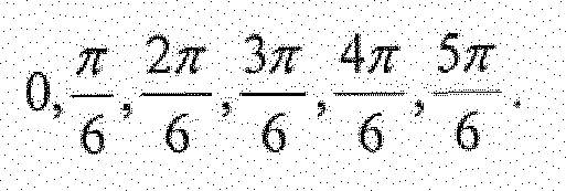
- a test region is thus initially defined for each key point. This is defined in the present example as a circle around the key point with a radius of 40 pixels (measuring points). Subsequently, for each measuring point which lies within the test region, as described above, the gradient orientation and the gradient amplitude are determined in a method step B1 .1. To align the gradient orientations according to the structure around the key point, the orientation of the structure around the key point is first determined as follows; The previously determined gradient orientations within the test region are mapped in an orientation histogram which has, for example, 36 bins, ie 36 individual categories which each cover a uniform orientation range. The result of such a classification is shown in FIG. 3a.
- the key point descriptor is determined for the key point, which was determined in particular as a function of the measurement data of the measurement points within the test region. So far, the key points have been determined, their orientation calculated and rotated the test region according to the key point orientation. This approach is known per se and described, for example, in (Lowe, D.G., Distinctive Image features from scale-invariant keypoints, International Journal of Computer Vision, 2004: p, 91-10).
- descriptor creation is, for example, the creation of a feature vector based on the gradient orientations. Every Orien The characteristic of a particular orientation results from the sum of the gradient amplitudes with this orientation,
- Polar sampling in particular is advantageous in this case since the cracks to be examined typically have higher gradient amplitudes close to the crack center compared to the measuring points located farther away. Therefore, a polar sampling » whose center coincides with the key point, in particular advantageous.
- a further advantage is that the above-mentioned rotation of the test region according to the key point orientation can be easily implemented in polar coordinates,
- a learning algorithm is finally trained in a method step D2 by means of the descriptors created and the crack data provided in method step B,
- the result of this embodiment of the method according to the invention is thus a prediction model created by training the support vector machine
- a semiconductor structure is provided and in a method step B, the prediction model described above is provided.
- a spatially resolved measurement of the semiconductor structure takes place. This is preferably carried out analogously to the spatially resolved photoluminescence measurement described in the first embodiment in accordance with method step C.
- measured data are thus present for a multiplicity of local measuring points of the semiconductor structure which correlate with the respective local intensity of the photoluminescence radiation produced.
- the determination for at least one local test point is made as to whether there is a crack at this test point.
- a descriptor is created in which a test region is specified or determined for the test point. This descriptor setting is the same as previously described in the first embodiment.
- the prediction model is applied in such a way that it is determined by means of the descriptor and the prediction model whether there is a crack at the checkpoint.
- a classification is possible in which corresponding key points are classified as points belonging to a crack or not belonging to a crack.
- a crack reconstruction is then carried out for the key points classified as belonging to a crack in method step D;
- the crack construction is done with the well-known method of hysteresis: starting at the key point, which is typically the crack center, the measurement point for measurement point is reconstructed the crack in its original form.
- the reconstruction is based on the assumption that the crack propagates in a star shape and on this basis the similarity of the crack environment with a star-shaped pattern is determined.
- a measuring point in the vicinity of the crack center thus probably belongs to the crack, if this measuring point lies on a beam structure, which starts from the Crack center spreads. It is therefore advantageous to calculate the orientation and filter response of a bar filter as described above for each location point.
- the orientations of the measurement points in the vicinity of the crack center are compared with the orientations of a star pattern.
- the cosine between the angle differences can preferably be calculated as a measure of similarity and weighted with the amplitude of the respective filter response.
- the resulting image, which results from the hysteresis is checked for its morphological properties.
Landscapes
- Physics & Mathematics (AREA)
- Health & Medical Sciences (AREA)
- General Physics & Mathematics (AREA)
- Chemical & Material Sciences (AREA)
- Biochemistry (AREA)
- Pathology (AREA)
- Immunology (AREA)
- Life Sciences & Earth Sciences (AREA)
- Engineering & Computer Science (AREA)
- Analytical Chemistry (AREA)
- General Health & Medical Sciences (AREA)
- Computer Vision & Pattern Recognition (AREA)
- Quality & Reliability (AREA)
- Theoretical Computer Science (AREA)
- Nuclear Medicine, Radiotherapy & Molecular Imaging (AREA)
- Testing Or Measuring Of Semiconductors Or The Like (AREA)
- Investigating Materials By The Use Of Optical Means Adapted For Particular Applications (AREA)
Abstract
Description

Claims
Priority Applications (3)
| Application Number | Priority Date | Filing Date | Title |
|---|---|---|---|
| DE112012002509.1T DE112012002509B4 (de) | 2011-06-17 | 2012-06-15 | Verfahren zur Bereitstellung eines Vorhersagemodells für eine Rissdetektion, Verfahren zur Rissdetektion an einer Halbleiterstruktur und Vorrichtung zur Rissdetektion an einer Halbleiterstruktur |
| CN201280038885.3A CN103733322B (zh) | 2011-06-17 | 2012-06-15 | 提供裂纹检测用预测模型的方法和检测半导体结构上的裂纹的方法 |
| HU1400302A HUP1400302A1 (hu) | 2011-06-17 | 2012-06-15 | Eljárás repedésdetektálásra szolgáló prediktív modell létrehozására, valamint eljárás félvezetõszerkezeten való repedésdetektálásra |
Applications Claiming Priority (2)
| Application Number | Priority Date | Filing Date | Title |
|---|---|---|---|
| DE102011105182A DE102011105182A1 (de) | 2011-06-17 | 2011-06-17 | Verfahren zur Bereitstellung eines Vorhersagemodells für eine Rissdetektion und Verfahren zur Rissdetektion an einer Halbleiterstruktur |
| DE102011105182.5 | 2011-06-17 |
Publications (1)
| Publication Number | Publication Date |
|---|---|
| WO2012172073A1 true WO2012172073A1 (de) | 2012-12-20 |
Family
ID=46384360
Family Applications (1)
| Application Number | Title | Priority Date | Filing Date |
|---|---|---|---|
| PCT/EP2012/061496 Ceased WO2012172073A1 (de) | 2011-06-17 | 2012-06-15 | Verfahren zur bereitstellung eines vorhersagemodells für eine rissdetektion und verfahren zur rissdetektion an einer halbleiterstruktur |
Country Status (4)
| Country | Link |
|---|---|
| CN (1) | CN103733322B (de) |
| DE (2) | DE102011105182A1 (de) |
| HU (1) | HUP1400302A1 (de) |
| WO (1) | WO2012172073A1 (de) |
Cited By (1)
| Publication number | Priority date | Publication date | Assignee | Title |
|---|---|---|---|---|
| DE102015119360A1 (de) | 2015-11-10 | 2017-05-11 | Albert-Ludwigs-Universität Freiburg | Verfahren und Vorrichtung zur Prüfung der Kontaktierungsgüte eines elektrischen Kontaktes zwischen einer Solarzelle und einer Kontaktierungseinheit |
Families Citing this family (8)
| Publication number | Priority date | Publication date | Assignee | Title |
|---|---|---|---|---|
| CN105869164A (zh) * | 2016-03-28 | 2016-08-17 | 国网浙江省电力公司宁波供电公司 | 一种开关分合状态检测方法及系统 |
| CN106814086B (zh) * | 2016-12-07 | 2019-12-27 | 青岛海尔股份有限公司 | 内胆开裂分析方法 |
| EP3367166A1 (de) * | 2017-02-24 | 2018-08-29 | ASML Netherlands B.V. | Verfahren zur messung einer variation, inspektionssystem, computerprogramm und computersystem |
| CN110431395A (zh) * | 2017-03-13 | 2019-11-08 | 通用电气公司 | 疲劳裂纹增长预测 |
| CN107389697B (zh) * | 2017-07-10 | 2019-08-30 | 北京交通大学 | 一种基于半交互式的裂缝检测方法 |
| EP3569147B1 (de) * | 2018-05-16 | 2021-07-21 | Siemens Healthcare GmbH | Verfahren und vorrichtung zum bestimmen einer geometriekalib-rierung für eine bildgebende vorrichtung sowie verfahren zum bestimmen von zuordnungsdaten für die geometriekalibrierung |
| CN108986086A (zh) * | 2018-07-05 | 2018-12-11 | 福州大学 | 印刷显示面板喷墨打印像素缺陷检测与分类方法及其装置 |
| EP3627568B1 (de) * | 2018-09-21 | 2024-03-27 | Fraunhofer-Gesellschaft zur Förderung der angewandten Forschung e.V. | Verfahren zur verarbeitung von abbildungen von halbleiterstrukturen, sowie zur prozesscharakterisierung und prozessoptimierung mittels semantischer datenkompression |
Family Cites Families (4)
| Publication number | Priority date | Publication date | Assignee | Title |
|---|---|---|---|---|
| JPH07201946A (ja) * | 1993-12-28 | 1995-08-04 | Hitachi Ltd | 半導体装置等の製造方法及びその装置並びに検査方法及びその装置 |
| DE19914115A1 (de) * | 1998-04-20 | 1999-11-04 | Gfai Ges Zur Foerderung Angewa | Verfahren und System zur Fehleranalyse bei polykristallinen Wafern, Solarzellen und Solarmodulen, insbesondere zur Bestimmung der prozeß- und strukturbedingten mechanischen Spannungen |
| US6539106B1 (en) * | 1999-01-08 | 2003-03-25 | Applied Materials, Inc. | Feature-based defect detection |
| US7096207B2 (en) * | 2002-03-22 | 2006-08-22 | Donglok Kim | Accelerated learning in machine vision using artificially implanted defects |
-
2011
- 2011-06-17 DE DE102011105182A patent/DE102011105182A1/de not_active Withdrawn
-
2012
- 2012-06-15 CN CN201280038885.3A patent/CN103733322B/zh not_active Expired - Fee Related
- 2012-06-15 HU HU1400302A patent/HUP1400302A1/hu unknown
- 2012-06-15 WO PCT/EP2012/061496 patent/WO2012172073A1/de not_active Ceased
- 2012-06-15 DE DE112012002509.1T patent/DE112012002509B4/de not_active Expired - Fee Related
Non-Patent Citations (13)
| Title |
|---|
| BAY, H.; TUYTELAARS, T.; GOOL, L.V.: "SURF: Speeded Up Robust Features", PROCEEDINGS OF THE NINTH EUROPEAN CONFERENCE ON COMPUTER VISION, May 2006 (2006-05-01) |
| BERNHARD SCHÖLKOPF; ALEX SMOLA: "Learning with Karnels: Support Vector Machines, Regutarization, Optimization, and Beyond (Adaptive Computation and Machine Learning", 2002, MIT PRESS, CAMBRIDGE. MA |
| C. HARRIS; M. STEPHENS: "A combined corner and edge detector", PROCEEDINGS OF THE 4TH ALVEY VISION CONFERENCE, 1988, pages 147 - 151 |
| DAVID G.: "Object recognition from local scale-invariant features", PROCEEDINGS OF THE INTERNATIONAL CONFERENCE ON COMPUTER VISION, vol. 2, 1999, pages 1150 - 1157 |
| DEMANT M ET AL: "Analysis of luminescence images applying pattern recognition techniques", EU PVSEC PROCEEDINGS : 25TH EUROPEAN PHOTOVOLTAIC SOLAR ENERGY CONFERENCE AND EXHIBITION / 5TH WORLD CONFERENCE ON PHOTOVOLTAIC ENERGY CONVERSION, 6-10 SEPTEMBER 2010, VALENCIA, SPAIN, WIP-RENEWABLE ENERGIES, DE, 1 September 2010 (2010-09-01), pages 1078 - 1082, XP009162280, ISBN: 978-3-936338-26-3 * |
| H. SCHULZ-MIRBACH: "Dissertation", February 1995, VDI-VERLAG, article "Anwendung von Invarianzprinzipien zur Merkmalgewinnung in der Mustererkennung" |
| J.MALIK: "Contour and Texture Analysis for Image Segmentation", INTERNATIONAL JOURNAL OF COMPUTER VISION, vol. 43, no. 1, 2001, pages 7 - 27, XP009039552, DOI: doi:10.1023/A:1011174803800 |
| KRYSTIAN MIKOLAJCZYK; CORDELIA SCHMID: "A performance evaluation of local descriptors", IEEE TRANSACTIONS ON PATTERN ANALYSIS AND MACHINE INTELLIGENCE, vol. 10, no. 27, 2005, pages 1615 - 1630 |
| LI BIN ET AL: "Automatic inspection of surface crack in solar cell images", CONTROL AND DECISION CONFERENCE (CCDC), 2011 CHINESE, IEEE, 23 May 2011 (2011-05-23), pages 993 - 998, XP031909684, ISBN: 978-1-4244-8737-0, DOI: 10.1109/CCDC.2011.5968329 * |
| LÖWE, D.G.: "Distinctive image features from scate-invariant keypoints", INTERNATIONAL JOURNAL OF COMPUTER VISION, 2004, pages 91 - 110 |
| MONASTYRSKYI, A. ET AL.: "Resonance Ultrasonic Vibrations for ln-Line Crack Detection in Silicon Wafers and Solar Cells", PROCEEDINGS OF 33RD PVSC, pages 2008 |
| SARFRAZ, S.; HELLWICH, O.: "Head Pose Estimation in Face Recognition across Pose Scena rios", PROCEEDINGS OF VISAPP 2008, INT. CONFERENCE ON COMPUTER VISION THEORY AND APPLICATIONS, MADEIRA, PORTUGAL, January 2008 (2008-01-01), pages 235 - 242 |
| TRUPKE, T.: "Progress with luminescence imaging for the characterisation of silicon wafers and soler cells", PROCEEDINGS OF THE 22ND EUROPEAN PHOTOVOLTAIC SOLAR ENERGY CONFERENCE, pages 2007 |
Cited By (1)
| Publication number | Priority date | Publication date | Assignee | Title |
|---|---|---|---|---|
| DE102015119360A1 (de) | 2015-11-10 | 2017-05-11 | Albert-Ludwigs-Universität Freiburg | Verfahren und Vorrichtung zur Prüfung der Kontaktierungsgüte eines elektrischen Kontaktes zwischen einer Solarzelle und einer Kontaktierungseinheit |
Also Published As
| Publication number | Publication date |
|---|---|
| CN103733322A (zh) | 2014-04-16 |
| DE102011105182A1 (de) | 2012-12-20 |
| DE112012002509B4 (de) | 2024-12-24 |
| HUP1400302A1 (hu) | 2014-10-28 |
| CN103733322B (zh) | 2017-11-24 |
| DE112012002509A5 (de) | 2014-12-04 |
Similar Documents
| Publication | Publication Date | Title |
|---|---|---|
| DE112012002509B4 (de) | Verfahren zur Bereitstellung eines Vorhersagemodells für eine Rissdetektion, Verfahren zur Rissdetektion an einer Halbleiterstruktur und Vorrichtung zur Rissdetektion an einer Halbleiterstruktur | |
| DE2823490C2 (de) | ||
| Marcos et al. | Automated pollen identification using microscopic imaging and texture analysis | |
| DE202022101590U1 (de) | Ein System zur Klassifizierung von Fernerkundungsbildern unter Verwendung fusionierter Faltungsmerkmale mit maschinellem Lernen | |
| DE112020005932T5 (de) | Systeme und verfahren zur segmentierung von transparenten objekten mittels polarisationsmerkmalen | |
| DE19521346C2 (de) | Bilduntersuchungs/-Erkennungsverfahren, darin verwendetes Verfahren zur Erzeugung von Referenzdaten und Vorrichtungen dafür | |
| DE60307583T2 (de) | Auswertung der Schärfe eines Bildes der Iris eines Auges | |
| Li et al. | Soft measurement of wood defects based on LDA feature fusion and compressed sensor images | |
| DE102013005489B4 (de) | Verfahren und Vorrichtung zur automatischen Fehlerstellenerkennung bei biegeschlaffen Körpern | |
| DE102009051826A1 (de) | Verfahren zum Vergleichen der Ähnlichkeit von 3D-bildlichen Objekten | |
| DE69322095T2 (de) | Verfahren und gerät zur identifizierung eines objekts mittels eine geordneten folge von grenz-pixel-parametern | |
| DE112019005143T5 (de) | System zur co-registrierung medizinischer bilder unter verwendung eines klassifikators | |
| CN108765412A (zh) | 一种带钢表面缺陷分类方法 | |
| DE102016120775A1 (de) | System und Verfahren zum Erkennen von Linien in einem Bild mit einem Sichtsystem | |
| CN107230203A (zh) | 基于人眼视觉注意机制的铸件缺陷识别方法 | |
| CN106651856A (zh) | 一种泡沫镍表面缺陷的检测方法 | |
| DE202009013865U1 (de) | Konzept zum Auswählen eines optimierten Bewertungsmerkmalsteilsatzes für eine Inspektion von Freiformoberflächen und Konzept zum Inspizieren einer Freiformoberfläche | |
| CN105931225A (zh) | 一种基于实时图像检测技术分析晶体生长形状和尺寸分布的方法 | |
| DE102015122116A1 (de) | System und Verfahren zur Ermittlung von Clutter in einem aufgenommenen Bild | |
| CN108364011A (zh) | PolSAR图像多级特征提取与无监督分类方法 | |
| CN115953352A (zh) | 基于网络模型的花生种子精选评估与分级方法 | |
| Patki et al. | A review: Cotton leaf disease detection | |
| EP3663976A1 (de) | Verfahren zur erfassung von fingerabdrücken | |
| DE112015006015T5 (de) | Zellanalysevorrichtung und Verfahren | |
| Joshi et al. | Detection and classification of plant diseases using soft computing techniques |
Legal Events
| Date | Code | Title | Description |
|---|---|---|---|
| 121 | Ep: the epo has been informed by wipo that ep was designated in this application |
Ref document number: 12729944 Country of ref document: EP Kind code of ref document: A1 |
|
| WWE | Wipo information: entry into national phase |
Ref document number: 112012002509 Country of ref document: DE Ref document number: 1120120025091 Country of ref document: DE |
|
| 122 | Ep: pct application non-entry in european phase |
Ref document number: 12729944 Country of ref document: EP Kind code of ref document: A1 |
|
| REG | Reference to national code |
Ref country code: DE Ref legal event code: R225 Ref document number: 112012002509 Country of ref document: DE Effective date: 20141204 |