WO2012169471A1 - Method and apparatus for inspecting neck finish of metal bottle - Google Patents
Method and apparatus for inspecting neck finish of metal bottle Download PDFInfo
- Publication number
- WO2012169471A1 WO2012169471A1 PCT/JP2012/064410 JP2012064410W WO2012169471A1 WO 2012169471 A1 WO2012169471 A1 WO 2012169471A1 JP 2012064410 W JP2012064410 W JP 2012064410W WO 2012169471 A1 WO2012169471 A1 WO 2012169471A1
- Authority
- WO
- WIPO (PCT)
- Prior art keywords
- bottle
- imaging
- inspection
- light
- illumination light
- Prior art date
Links
Images


Classifications
-
- G—PHYSICS
- G01—MEASURING; TESTING
- G01N—INVESTIGATING OR ANALYSING MATERIALS BY DETERMINING THEIR CHEMICAL OR PHYSICAL PROPERTIES
- G01N21/00—Investigating or analysing materials by the use of optical means, i.e. using sub-millimetre waves, infrared, visible or ultraviolet light
- G01N21/84—Systems specially adapted for particular applications
- G01N21/88—Investigating the presence of flaws or contamination
- G01N21/90—Investigating the presence of flaws or contamination in a container or its contents
-
- B—PERFORMING OPERATIONS; TRANSPORTING
- B07—SEPARATING SOLIDS FROM SOLIDS; SORTING
- B07C—POSTAL SORTING; SORTING INDIVIDUAL ARTICLES, OR BULK MATERIAL FIT TO BE SORTED PIECE-MEAL, e.g. BY PICKING
- B07C5/00—Sorting according to a characteristic or feature of the articles or material being sorted, e.g. by control effected by devices which detect or measure such characteristic or feature; Sorting by manually actuated devices, e.g. switches
- B07C5/34—Sorting according to other particular properties
- B07C5/3404—Sorting according to other particular properties according to properties of containers or receptacles, e.g. rigidity, leaks, fill-level
- B07C5/3408—Sorting according to other particular properties according to properties of containers or receptacles, e.g. rigidity, leaks, fill-level for bottles, jars or other glassware
-
- G—PHYSICS
- G01—MEASURING; TESTING
- G01N—INVESTIGATING OR ANALYSING MATERIALS BY DETERMINING THEIR CHEMICAL OR PHYSICAL PROPERTIES
- G01N21/00—Investigating or analysing materials by the use of optical means, i.e. using sub-millimetre waves, infrared, visible or ultraviolet light
- G01N21/84—Systems specially adapted for particular applications
- G01N21/88—Investigating the presence of flaws or contamination
- G01N21/95—Investigating the presence of flaws or contamination characterised by the material or shape of the object to be examined
- G01N21/9515—Objects of complex shape, e.g. examined with use of a surface follower device
-
- G—PHYSICS
- G01—MEASURING; TESTING
- G01N—INVESTIGATING OR ANALYSING MATERIALS BY DETERMINING THEIR CHEMICAL OR PHYSICAL PROPERTIES
- G01N21/00—Investigating or analysing materials by the use of optical means, i.e. using sub-millimetre waves, infrared, visible or ultraviolet light
- G01N21/84—Systems specially adapted for particular applications
- G01N21/88—Investigating the presence of flaws or contamination
- G01N21/90—Investigating the presence of flaws or contamination in a container or its contents
- G01N21/9054—Inspection of sealing surface and container finish
-
- G—PHYSICS
- G01—MEASURING; TESTING
- G01N—INVESTIGATING OR ANALYSING MATERIALS BY DETERMINING THEIR CHEMICAL OR PHYSICAL PROPERTIES
- G01N21/00—Investigating or analysing materials by the use of optical means, i.e. using sub-millimetre waves, infrared, visible or ultraviolet light
- G01N21/84—Systems specially adapted for particular applications
- G01N21/88—Investigating the presence of flaws or contamination
- G01N21/90—Investigating the presence of flaws or contamination in a container or its contents
- G01N21/909—Investigating the presence of flaws or contamination in a container or its contents in opaque containers or opaque container parts, e.g. cans, tins, caps, labels
-
- G—PHYSICS
- G01—MEASURING; TESTING
- G01N—INVESTIGATING OR ANALYSING MATERIALS BY DETERMINING THEIR CHEMICAL OR PHYSICAL PROPERTIES
- G01N21/00—Investigating or analysing materials by the use of optical means, i.e. using sub-millimetre waves, infrared, visible or ultraviolet light
- G01N21/84—Systems specially adapted for particular applications
- G01N21/88—Investigating the presence of flaws or contamination
- G01N21/95—Investigating the presence of flaws or contamination characterised by the material or shape of the object to be examined
Definitions
- the present invention relates to a method and an inspection apparatus for a cap part of a bottle can.
- a bottle-shaped can made of an aluminum alloy in which a cap is screwed onto a base portion having a male screw is known as a container filled with contents such as beverages.
- the can is formed by forming an aluminum alloy plate into a bottomed cylindrical body in which the bottom plate and the cylindrical side surface are integrated by drawing and ironing (DI molding), coating the inner and outer surfaces, and then opening the so-called neck at the opening.
- DI molding drawing and ironing
- the shoulder portion and the base portion are formed by performing in-processing, and the base portion is manufactured by performing screw forming processing, curling portion forming processing, or the like.
- the inner surface coating film in such a can is formed by using a thermosetting resin such as an epoxy acrylic resin or a polyester resin to provide the can with corrosion resistance to the filling (see Patent Document 1). .
- the inner surface coating is formed by spraying paint onto the inner surface after drawing and ironing and before neck-in processing, but the paint scatters around and adheres to the outer surface of the can to form minute protrusions. As a result, there may be a problem that it becomes a starting point for generating wrinkles during neck-in processing.
- the curl part is formed by bending the upper end of the base part to the outer peripheral side, and the coating film on the inner surface is formed on the surface.
- the can is sealed by attaching a cap so as to press the liner against the curled portion (see Patent Document 2). Therefore, if the surface of the curled part, particularly the top surface, is formed with uneven shapes such as wrinkles due to the coating film as described above, or the curled part is deformed such as a dent, the contents may leak. There is. However, an uneven shape may be formed on the surface of the curled portion due to the coating film on the inner surface becoming wrinkled during molding of the base portion and molding of the curled portion.
- illumination light is obliquely applied to the tangent plane (surface along the tangential direction of the outer surface) of the can body, and the reflected light from the wrinkles
- Patent Document 3 A method for detecting wrinkles by observing the shadow and shadow along the tangential plane direction has been proposed (see Patent Document 3).
- the uneven shape of the curled part will cause liquid leakage, so it must be detected reliably, but the color without the uneven shape such as a rolled pattern of aluminum material, punch pattern or dirt during DI molding The pattern does not affect the sealing performance and need not be rejected as a defective product. If such a color pattern is detected as a concavo-convex shape, a non-defective product may be excluded as a defective product and the yield may be reduced.
- Patent Document 3 Since the detection method described in Patent Document 3 detects wrinkles by confirming the shadow of the illumination light irradiated on the can, there is little risk of detecting a color pattern as defective by this method. However, it is necessary to dispose the can at an accurate position with respect to the illumination light and the camera. If the can is displaced from the inspection position, it may be difficult to obtain an accurate detection result.
- such an inspection apparatus has a problem that the production efficiency deteriorates because the processing time of each inspection is long.
- the number of imaging devices is increased and a plurality of inspection devices are provided, a plurality of cans can be inspected at a time, so that the processing time can be shortened, but there is a problem that the cost of configuring the inspection device increases. Arise.
- the present invention has been made in view of such circumstances, and can reliably detect only bottle cans having irregular shapes such as scratches that may cause liquid leakage and the like, and can reduce the processing time of inspection.
- a method and apparatus for inspecting a base of a bottle can with excellent productivity.
- the bottle can base part inspection method of the present invention is the bottle can having a cylindrical base part provided with a curled part in which an open end is curled outward in order to fit a cap with a liner.
- a method of detecting an uneven shape of the curled part by imaging an imaging area set to include a part of the curled part while rotating a bottle can around a can axis, and continuously along a main conveyance path
- the curled portion in the imaging area of the bottle cans that are sequentially conveyed is imaged by irradiating white light to detect the presence or absence of a low-luminance region from the obtained black and white inspection image.
- a primary inspection process for removing bottle cans in which a luminance area is detected, and the imaging area while sequentially transporting the bottle cans excluded by the primary inspection process along a sub-conveyance path retracted from the main conveyance path In the above The two color illumination lights are irradiated from different directions along the substantially tangential direction of the cylindrical surface of the base part, and imaged from the signal intensity of each light color of the obtained color inspection image.
- the region where the rolling pattern, punch pattern, dirt, etc. are present has a different color from the other regions, so that the amount of white light reflected from the white light source changes and becomes a low luminance region.
- the primary inspection process by irradiating the curled portion of the imaging area with white light, not only irregular shapes such as scratches, but also two-dimensional dirt without irregularities is detected as a low luminance region.
- the bottle can in which the luminance region is detected regardless of whether it has an uneven shape, it is possible to instantaneously select bottle cans that are free from dirt and unevenness. Only the bottle cans that are free of dirt and irregularities are transported along the main transport path and removed in the primary inspection process, and are sent to the sub transport path for secondary inspection.
- the illumination light of two colors is irradiated to the curled portion of the imaging area from different directions, so that the reflected light by the uneven shape formed to block the illumination light is the light of each illumination light. Images are taken in the form of stripes of two colors according to the color. On the other hand, the reflected light due to dirt or the like without unevenness is not striped, but is imaged as a shade of mixed colors of each illumination light. Therefore, it is possible to reliably detect uneven shapes that cause liquid leakage, there is no risk of misidentifying dirt and the like as uneven shapes, and there is no problem in the sealing between the opening of the bottle can and the cap, etc. Therefore, only bottle cans having irregular shapes such as scratches can be reliably excluded.
- the secondary inspection step in the secondary inspection step, light different from the illumination light of the two colors is applied to a portion of the curl portion irradiated with the illumination light of the two colors.
- the color third illumination light may be irradiated from a direction intersecting with the two color illumination lights.
- the edge position of the curled portion can be detected by the reflected light of the third illumination light, and the curled portion in the color inspection image can be specified based on the edge position, so that the shape of the curled portion becomes clear. Dents and distortions of the curled portion can be detected. Further, if the can axis and the rotation axis of the rotating means are shifted when the bottle can is rotated, the curled portion moves in the inspection image, but the curled portion can be specified by detecting the edge position of the curled portion. Therefore, the curled portion can be inspected reliably.
- the bottle can mouthpiece inspection device of the present invention relates to the bottle can having a cylindrical mouthpiece portion provided with a curled portion with an open end curled outward in order to fit a cap with a liner.
- An apparatus for detecting an uneven shape of the curled part by imaging an imaging area set to include a part of the curled part while rotating the bottle can around the axis of the can.
- the primary inspection means holds the bottle can and rotates it around the can axis, and the curl portion in the imaging area.
- a white light illuminating unit that emits white light
- a primary imaging unit that captures the imaging area in black and white
- a low-intensity area detected from the black and white inspection image obtained by the primary imaging unit.
- the Secondary inspection means holding the bottle can removed by the primary inspection means and rotating it around the can axis, and the bottle
- the curl portion in the imaging area of the can is irradiated with first illumination light that irradiates the first illumination light along a substantially tangential direction of the cylindrical surface of the base portion, and the first illumination light at the curl portion is irradiated.
- Second illumination means for irradiating second illumination light of a light color different from that of the first illumination means along the substantially tangential direction of the base from the opposite side of the first illumination light across the imaging area; , Determining whether the bottle can is good or not by determining the presence or absence of uneven shapes based on the signal intensity of each light color of the color inspection image obtained by the secondary imaging means and the color imaging image obtained by the secondary imaging means Secondary determination means.
- the secondary inspection means is a light different from the illumination light of the two colors for the portion of the curl portion irradiated with the illumination light of the two colors. It is good to provide the 3rd illumination means to irradiate the color 3rd illumination light from the direction which cross
- bottle cans having irregular shapes such as scratches can be surely eliminated, the processing time for inspection can be shortened, and the production efficiency of bottle cans can be improved.
- FIG. 1 It is the schematic which shows the nozzle
- FIG. 1 it is a schematic diagram which shows the reflection state of the illumination light of 2 colors in uneven
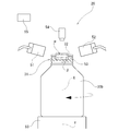
- the base part inspection apparatus 100 shown in FIG. 1 curls the opening end outward in order to fit a cap with a liner (not shown).
- the bottle can 30 having the cylindrical base part 31 provided with the curled part 32 is set so as to include a part of the curled part 32 (part of the top surface in the present embodiment) as shown in FIG. This is a device for detecting the uneven shape of the curled portion 32 in the imaging area ⁇ .
- the bottle cans 30 to be inspected by the inspection apparatus 100 are transported in a single row by a main transport path 101 such as a conveyor in the production line as shown in FIG. And in the middle of this main conveyance path 101, inspection device 100 which inspects mouthpiece part 31 while rotating each bottle can 30 is provided.
- a main transport path 101 such as a conveyor in the production line as shown in FIG.
- inspection device 100 which inspects mouthpiece part 31 while rotating each bottle can 30 is provided.
- the inspection apparatus 100 irradiates the curled portion 32 in the imaging area ⁇ of the bottle can 30 that is continuously and sequentially transported along the main transport path 101 to capture the white light W.
- the primary inspection means 10 that detects the low luminance area from the obtained black and white inspection image and excludes the bottle can 30b in which the low luminance area is detected, and the bottle can 30b excluded by the primary inspection means 10 While sequentially transporting along the sub-transport path 102 retracted from the main transport path 101, imaging is performed by irradiating the curled portion 32 in the imaging area ⁇ of the bottle can 30b with illumination light of two colors from different directions.
- the second inspection means 20 includes a secondary inspection means 20 that determines the presence or absence of the uneven shape from the signal intensity of each light color of the obtained color inspection image and determines the quality of the bottle can 30b.
- the primary inspection means 10 is white with respect to the primary rotation means 40 that holds the bottle can 30 and rotates it around the can axis X, and the curl portion 32 in the imaging area ⁇ .
- the white light illuminating means 41 is arranged so as to irradiate obliquely from above toward the base portion 31 (part of the top surface of the curled portion 32) of the imaging area ⁇ . Further, the primary imaging means 42 is arranged above the base portion 31 of the bottle can 30 toward the imaging area ⁇ (that is, toward the top surface of the curled portion 32).
- the secondary inspection means 20 includes a secondary rotation means 50 that holds the bottle can 30 b removed by the primary inspection means 10 and rotates it around the can axis, and in the imaging area ⁇ .
- the third illuminating means 53 for irradiating the third illuminating light G on the portion irradiated with the first illuminating light R and the second illuminating light B at the curled portion 32, and the reflected light at the curled portion 32.
- the 1st illumination means 51 and the 2nd illumination means 52 are arrange
- the third illuminating unit 53 applies the third illuminating light G to the outer peripheral surface (edge detection area ⁇ ) that is bent and continuous from the portion irradiated with the first illuminating light R and the second illuminating light B in the curled portion 32. It is arranged to irradiate.
- the first illumination means 51 is disposed on the side of the base portion 31 of the bottle can 30 b, and the red first illumination light R is emitted from the curl portion 32 in the imaging area ⁇ .
- the surface is irradiated along the substantially tangential direction of the cylindrical surface of the base 31.
- the second illumination unit 52 is disposed on the opposite side of the first illumination unit 51 across the imaging area ⁇ , and is blue (light color different from the red first illumination light R).
- the second illumination light B is irradiated along the substantially tangential direction of the cylindrical surface of the base 31 to the portion of the curl portion 32 irradiated with the first illumination light R.
- the first illumination light 51 and the second illumination light 52 overlap the curled portion 32 of the imaging area ⁇ from different directions as shown in FIG. Is irradiated.
- the edge detection area ⁇ is bent and continuous from the imaging area ⁇ , and is set to include the outer peripheral surface of the curled portion 32.
- the third illumination means 53 is disposed on the side of the base portion 31 of the bottle can 30b, and from the direction intersecting the first illumination light R and the second illumination light B, that is, the base
- the curl portion 32 of the edge detection area ⁇ of the third illumination light G of green color (light color different from the first illumination light R and the second illumination light B) in a direction substantially orthogonal to the tangential direction of the cylindrical surface of the portion 31. Irradiate the outer peripheral surface of
- the secondary imaging unit 54 is disposed above the base portion 31 of the bottle can 30 b toward the imaging area ⁇ (that is, toward the top surface of the curled portion 32). A color inspection image including each reflected light at 32 can be captured.
- the bottle cans 30 are transported in a single row by a main transport path 101 such as a conveyor in the production line, and inspected by the inspection apparatus 100 that inspects the base part 31 while rotating each bottle can 30 in the middle of the main transport path 101. Done.
- a main transport path 101 such as a conveyor in the production line
- Each bottle can 30 is continuously transported to the primary inspection means 10 along the main transport path 101 and subjected to primary inspection.
- the bottle can 30 is rotated around the can axis X by the primary rotation means 40 with respect to the white light illumination means 41 and the primary imaging means 42, thereby the base portion 31.
- the primary rotation means 40 with respect to the white light illumination means 41 and the primary imaging means 42, thereby the base portion 31.
- the monochrome inspection image is input to the primary determination unit 43 connected to the primary imaging unit 42.
- the primary determination unit 43 connected to the primary imaging unit 42 takes in the black and white inspection image acquired by the primary imaging unit 42, detects the presence or absence of the low luminance region from the black and white inspection image, and detects the low luminance region.
- the detected bottle can 30b is excluded.
- the bottle can 30b is excluded when a low-luminance region having a predetermined size or more is detected in the black and white inspection image.
- the bottle can 30a having no dirt or irregularities is instantly selected. Then, the bottle can 30a having no dirt or irregularities is transported along the main transport path 101, and only the bottle can 30b in which the low luminance area is detected is sent to the sub transport path 102 for secondary inspection.
- the secondary conveyance path 102 is set to have a conveyance speed slower than that of the main conveyance path 101, and the secondary inspection unit 20 performs a precise inspection on the bottle can 30 b excluded by the primary inspection unit 10.
- the secondary inspection means 20 rotates the bottle can 30b around the can axis X by the secondary rotation means 50 with respect to each of the illumination means 51 to 53 and the secondary imaging means 54. Scanning is performed, and a color inspection image including each reflected light in the curled portion 32 is captured.
- the color inspection image is input to the secondary determination unit 55 connected to the secondary imaging unit 54, and is used to determine the quality of the bottle can 30b.
- the secondary determination means 55 connected to the secondary image pickup means 54 takes in the color inspection image acquired by the secondary image pickup means 54 and makes a pass / fail determination of the bottle can 30b based on the color inspection image.
- the secondary determination means 55 determines that the bottle can is “no” when detecting an uneven shape that causes liquid leakage from the color inspection image, and has only two-dimensional dirt and the like. A bottle can that does not have a problem such as liquid leakage is determined as “good”. Then, the bottle can 30c determined as “No” is excluded from the production line along the sub-transport path 102, and the bottle can 30a determined as “good” is returned to the main transport path 101.
- the recognition of the uneven shape will be described more specifically. If the curled portion 32 is flat and has no uneven shape, the purple uniform reflected light p, which is a mixed color of the first illumination light R and the second illumination light B, is imaged on the top surface T of the inspection image (FIG. 6). Further, a portion a of a color pattern such as a flat rolled pattern, a punch pattern, or a stain becomes reflected light p having a different purple shade.
- the curled portion 32 has a concavo-convex shape (for example, a dent 33) that changes the reflection direction of each illumination light
- the first illumination light R and the second illumination light B are emitted from different directions in the same manner.
- red reflected light r or blue reflected light b is generated according to the shape of the recess 33 as shown in FIG.
- the secondary determination means 55 detects such reflected lights r and b, it can be seen that a concave and convex shape such as a recess 33 is formed in the curled portion 32.
- the dent 33 extended in the radial direction of the bottle can 30b in the curl part 32 is detected.
- the reflected light g of the third illumination light G in the edge detection area ⁇ is detected as shown in FIG.
- the secondary determination unit 55 detects the edge position of the imaging area ⁇ from the reflected light g, and specifies the imaging area ⁇ in the color inspection image with the edge position as a reference.
- the imaging of the reflected light g of the third illumination light G is tracked by a computer (not shown) that captures the color inspection image, and this imaging is used as an edge of the curled portion 32 to have a predetermined width from this edge. Is determined as the imaging area ⁇ .
- the imaging of the reflected light r of the first illumination light R and the reflected light b of the second illumination light B existing in the imaging area ⁇ is recognized, and the uneven shape is determined from the result. If the displacement of the imaging of the reflected light g of the third illumination light G exceeds a predetermined value of the radial displacement of the curled portion 32, it is determined that the edge abnormality is defective.
- reflected light g having a shape corresponding to the shape of the dent 34 is generated as shown in FIG.
- detecting the reflected light g having a shape it is possible to detect the dent 34 formed on the edge portion of the curled portion 32.
- the uneven shape such as the scratch 35 formed on the edge portion of the curled portion 32 causes irregular reflection of the third illumination light G. By detecting such irregular reflection, the scratch on the outer peripheral surface of the curled portion 32 is detected. 35 can be detected.
- the reflected light g of the edge detection area ⁇ also exhibits a curved shape according to the shape thereof. By detecting such a shape, The curved portion 36 of the curled portion 32 can be detected.
- each inspection means of the inspection apparatus 100 the entire circumference of the base part 31 can be scanned by rotating the bottle can 30 by the respective rotation means 40 and 50.
- the position of the curled portion 32 is greatly meandered, and it becomes difficult to find defects such as bending of the curled portion 32.
- the green reflected light g from the edge detection area ⁇ indicates the edge position E of the curled portion 32
- Inspection can be performed while the curled portion 32 is specified. Further, by detecting the local deformation 37 of the green reflected light g, it is possible to detect a defect such as a curved deformation of the curled portion 32.
- the reflected light r of the red first illumination light R and the reflected light b of the blue second illumination light B are mixed and incident on the secondary imaging means 54, and the purple reflected light p is detected. Since the first illumination light R and the second illumination light B are reflected also on the portion of the color pattern without unevenness such as dirt and rolling pattern attached to the curled portion 32, the purple reflected light p is detected.
- the curled portion 32 has an uneven shape such as a dent 33 that prevents the illumination light R and B from being incident, the illumination light R and B are irradiated from different directions, so that the shape depends on the uneven shape.
- the first illumination light R is not applied to the non-reflecting portion 33 a on the inner surface of the recess 33. For this reason, the red reflected light r by the first illumination light R enters the secondary imaging means 54 with the non-reflecting portion 33a as a shadow.
- the second illumination light B irradiated from a direction different from the first illumination light R is not irradiated to the non-reflecting portion 33 b on the inner surface of the recess 33.
- the blue reflected light b by the second illumination light B is incident on the secondary imaging means 54 with the non-reflecting portion 33b as a shadow. That is, blue reflected light b is incident on the secondary imaging means 54 from the non-reflecting portion 33 a and red reflected light r is incident on the non-reflecting portion 33 b.
- the mixed color reflected light p is detected from a flat portion having no uneven shape in the curled portion 32.
- red reflected light r and blue reflected light b are detected from the inner surface of the recess 33. Therefore, it can be seen that a concavo-convex shape such as the dent 33 is generated in the portion where the monochromatic reflected lights b and r corresponding to the respective colors of the illumination lights R and B are detected.
- the first illumination light R and the second illumination light B have a complementary color relationship with each other, the monochromatic reflected lights r and b are clearly detected, so that the uneven shape can be reliably detected.
- all bottle cans in which low luminance areas are detected regardless of whether or not they have an uneven shape while inspecting at high speed in the primary inspection process using white light By eliminating and precisely inspecting only the bottle can in the secondary inspection process using the color inspection image, it is possible to surely eliminate bottle cans having irregular shapes such as scratches and shorten the inspection processing time. .
- each of the main transport path and the sub transport path is provided with only one path, but a plurality of them may be provided in parallel.
- a plurality of bottles in parallel a plurality of bottle cans can be inspected simultaneously, and the inspection processing time can be further shortened.
- the imaging area which irradiates 1st illumination light and 2nd illumination light is set to the top
- the imaging area ⁇ is set on the outer peripheral surface of the curled portion 32
- the edge detection area ⁇ is set on the top surface of the curled portion 32, as shown in FIG. Also good.
- the inspection apparatus of the said embodiment it is set as the structure provided with 1 set of 1st illumination means and 2nd illumination means, and directs 1st illumination light and 2nd illumination light to the top
- a plurality of sets of first illumination means and second illumination means may be provided.
- each illumination light is blocked by the convex surface, so that the inner peripheral side of the curled portion top surface cannot be irradiated.
- upper surface of a curl part can be detected, it is difficult to detect the uneven
- the top surface of the curled portion 32 is provided by providing a second set of first illumination means 51A and second illumination means 52A for irradiating illumination light from the inner peripheral side of the base portion 31 toward the top surface of the curl portion 32. A wide range can be inspected.
- a method and apparatus for inspecting a cap part of a bottle can excellent in productivity that can reliably detect only bottle cans having irregular shapes such as scratches that may cause liquid leakage and the like, and can reduce the processing time of inspection. I will provide a.
- Base inspection apparatus 10 Primary inspection means 20 Secondary inspection means 30, 30a, 30b, 30c Bottle can 31 Base part 32 Curl part 33 Recess 33a, 33b Non-reflective part 34 Scratch 35 Scratch 36 Bending part 37 Deformation 40 1 Secondary rotation means 41 White light illumination means 42 Primary imaging means 43 Primary determination means 50 Secondary rotation means 51, 51A First illumination means 52, 52A Second illumination means 53 Third illumination means 54 Secondary imaging means 55 Secondary Determination means R First illumination light B Second illumination light G Third illumination light r Red reflected light b Blue reflected light g Green reflected light p Purple reflected light X Can axis Y Rotating axis ⁇ Imaging area ⁇ Edge detection area E Edge position T Top
Landscapes
- Physics & Mathematics (AREA)
- Health & Medical Sciences (AREA)
- Life Sciences & Earth Sciences (AREA)
- Chemical & Material Sciences (AREA)
- Analytical Chemistry (AREA)
- Biochemistry (AREA)
- General Health & Medical Sciences (AREA)
- General Physics & Mathematics (AREA)
- Immunology (AREA)
- Pathology (AREA)
- Investigating Materials By The Use Of Optical Means Adapted For Particular Applications (AREA)
Abstract
Description
各ボトル缶30は、主搬送路101に沿って1次検査手段10に連続的に搬送され、1次検査される。1次検査手段10では、ボトル缶30を、白色光照明手段41および1次撮像手段42に対して、1次回転手段40によってボトル缶30を缶軸Xまわりに回転させることにより、口金部31の全周を走査し、撮像エリアαの白黒検査画像を撮像する。白黒検査画像は、1次撮像手段42に接続された1次判定手段43に入力される。 (Primary inspection process)
Each bottle can 30 is continuously transported to the primary inspection means 10 along the
副搬送路102は、主搬送路101と比べて搬送速度が遅く設定されており、2次検査手段20では、1次検査手段10で排除されたボトル缶30bについて精密な検査が行われる。2次検査手段20は、各照明手段51~53および2次撮像手段54に対して、ボトル缶30bを2次回転手段50によって缶軸Xまわりに回転させることにより、口金部31の全周を走査し、カール部32における各反射光を含むカラー検査画像を撮像する。カラー検査画像は、2次撮像手段54に接続された2次判定手段55に入力され、ボトル缶30bの良否判定に用いられる。 (Secondary inspection process)
The
10 1次検査手段
20 2次検査手段
30,30a,30b,30c ボトル缶
31 口金部
32 カール部
33 凹み
33a,33b 非反射部
34 打痕
35 傷
36 湾曲部
37 変形
40 1次回転手段
41 白色光照明手段
42 1次撮像手段
43 1次判定手段
50 2次回転手段
51,51A 第1照明手段
52,52A 第2照明手段
53 第3照明手段
54 2次撮像手段
55 2次判定手段
R 第1照明光
B 第2照明光
G 第3照明光
r 赤色の反射光
b 青色の反射光
g 緑色の反射光
p 紫色の反射光
X 缶軸
Y 回転軸
α 撮像エリア
β エッジ検出エリア
E エッジ位置
T 天面 100
Claims (5)
- ライナー付キャップを被嵌するために開口端を外方へ向かってカールさせたカール部が設けられた円筒状の口金部を有するボトル缶について、前記ボトル缶を缶軸まわりに回転させながら前記カール部の一部を含むように設定された撮像エリアを撮像して前記カール部の凹凸形状を検出する方法であって、
主搬送路に沿って連続的に順次搬送される前記ボトル缶の前記撮像エリア内の前記カール部に対して白色光を照射して撮像を行い、得られた白黒検査画像から低輝度領域の有無を検知して、該低輝度領域が検知されたボトル缶を排除する1次検査工程と、
前記1次検査工程によって排除されたボトル缶を前記主搬送路から退避した副搬送路に沿って順次搬送しながら、前記撮像エリア内の前記カール部に対して、前記口金部の円筒面略接線方向に沿って2色の照明光をそれぞれ異なる方向から照射して撮像を行い、得られたカラー検査画像の各光色の信号強度から前記カール部における前記凹凸形状の有無を判別し、ボトル缶の良否を判定する2次検査工程と
を備えることを特徴とするボトル缶の口金部検査方法。 For a bottle can having a cylindrical base portion provided with a curled portion with an open end curled outward to fit a cap with a liner, the curl is rotated while the bottle can is rotated around a can axis. A method of detecting an uneven shape of the curled portion by imaging an imaging area set to include a part of the portion,
Examine the curled part in the imaging area of the bottle can that is sequentially and sequentially conveyed along the main conveyance path to shoot white light and image the presence or absence of a low luminance area from the obtained black and white inspection image A primary inspection step of detecting a bottle can in which the low luminance region is detected;
The cylindrical can of the base part is substantially tangent to the curl part in the imaging area while sequentially transporting the bottle cans removed in the primary inspection process along the sub-transport path retracted from the main transport path. An image is obtained by irradiating two colors of illumination light from different directions along the direction, and the presence or absence of the uneven shape in the curled portion is determined from the signal intensity of each light color of the obtained color inspection image. A method for inspecting a cap part of a bottle can, comprising: a secondary inspection step for determining whether the quality of the bottle is good. - 前記2次検査工程では、前記カール部における前記2色の照明光が照射された部分に対して、前記2色の照明光とは異なる光色の第3照明光を、前記2色の照明光に交差する方向から照射することを特徴とする請求項1記載のボトル缶の口金部検査方法。 In the secondary inspection step, a third illumination light having a light color different from the illumination light of the two colors is applied to a portion of the curled portion irradiated with the illumination light of the two colors. 2. The method for inspecting a cap part of a bottle can according to claim 1, wherein irradiation is performed from a direction intersecting with the bottle.
- ライナー付キャップを被嵌するために開口端を外方へ向かってカールさせたカール部が設けられた円筒状の口金部を有するボトル缶について、前記ボトル缶を缶軸まわりに回転させながら前記カール部の一部を含むように設定された撮像エリアを撮像して前記カール部の凹凸形状を検出する装置であって、
ボトル缶を順次搬送する主搬送路と、前記主搬送路に沿って連続的に順次搬送される前記ボトル缶の前記撮像エリア内の前記カール部に対して白色光を照射して撮像を行い、得られた白黒検査画像から低輝度領域の有無を検知して、該低輝度領域が検知されたボトル缶を排除する1次検査手段と、
前記1次検査手段によって排除されたボトル缶を搬送する副搬送路と、
前記副搬送路に沿って前記ボトル缶を順次搬送しながら、前記撮像エリア内の前記カール部に対して2色の照明光をそれぞれ異なる方向から照射して撮像を行い、得られたカラー検査画像の各光色の信号強度から前記カール部における前記凹凸形状の有無を判別し、ボトル缶の良否を判定する2次検査手段と
を備えることを特徴とするボトル缶の口金部検査装置。 For a bottle can having a cylindrical base portion provided with a curled portion with an open end curled outward to fit a cap with a liner, the curl is rotated while the bottle can is rotated around a can axis. An apparatus for detecting an uneven shape of the curled part by imaging an imaging area set to include a part of the part,
A main conveyance path that sequentially conveys the bottle cans, and performs imaging by irradiating white light to the curled portion in the imaging area of the bottle cans that are sequentially and sequentially conveyed along the main conveyance path, Primary inspection means for detecting the presence or absence of a low-luminance region from the obtained black-and-white inspection image and excluding the bottle can in which the low-luminance region is detected;
A sub-transport path for transporting the bottle can removed by the primary inspection means;
A color inspection image obtained by performing imaging by irradiating the curled portion in the imaging area with illumination light of two colors from different directions while sequentially transporting the bottle cans along the sub-transport path. And a secondary inspection means for determining the quality of the bottle can by determining the presence or absence of the uneven shape in the curled portion from the signal intensity of each light color. - 前記1次検査手段は、
前記ボトル缶を保持して缶軸まわりに回転させる1次回転手段と、
前記撮像エリア内の前記カール部に対して白色光を照射する白色光照明手段と、
前記撮像エリアを白黒で撮像する1次撮像手段と、
前記1次撮像手段により得られた白黒検査画像から低輝度領域を検知し、その検知結果に基づきボトル缶を排除する1次判定手段と
を備え、前記2次検査手段は、
前記1次検査手段によって排除されたボトル缶を保持して缶軸まわりに回転させる2次回転手段と、
該ボトル缶の撮像エリア内の前記カール部に対して、前記口金部の円筒面略接線方向に沿って第1照明光を照射する第1照明手段と、
前記カール部における前記第1照明光が照射された部分に対して、前記第1照明手段とは異なる光色の第2照明光を、前記撮像エリアを挟んで前記第1照明光の反対側から、前記口金部の前記略接線方向に沿って照射する第2照明手段と、
前記撮像エリアをカラーで撮像する2次撮像手段と、前記2次撮像手段により得られたカラー検査画像の各光色の信号強度に基づき凹凸形状の有無を判別し、ボトル缶の良否を判定する2次判定手段と
を備えることを特徴とする請求項3記載のボトル缶の口金部検査装置。 The primary inspection means includes
Primary rotating means for holding the bottle can and rotating it around the can axis;
White light illumination means for irradiating the curled portion in the imaging area with white light;
Primary imaging means for imaging the imaging area in black and white;
Primary detection means for detecting a low luminance area from the black and white inspection image obtained by the primary imaging means, and eliminating the bottle can based on the detection result, the secondary inspection means,
Secondary rotating means for holding the bottle can removed by the primary inspection means and rotating it around the can axis;
A first illuminating means for irradiating the curl portion in the imaging area of the bottle can with a first illumination light along a substantially tangential direction of the cylindrical surface of the base portion;
The second illumination light of a light color different from that of the first illumination means is applied to the portion of the curl portion irradiated with the first illumination light from the opposite side of the first illumination light across the imaging area. Second illumination means for irradiating along the substantially tangential direction of the base part;
Secondary imaging means for imaging the imaging area in color, and the presence or absence of uneven shapes based on the signal intensity of each light color of the color inspection image obtained by the secondary imaging means, to determine the quality of the bottle can The apparatus for inspecting a cap part of a bottle can according to claim 3, further comprising secondary determination means. - 前記2次検査手段は、前記カール部における前記2色の照明光が照射された部分に対して、前記2色の照明光とは異なる光色の第3照明光を、前記2色の照明光に交差する方向から照射する第3照明手段を備えていることを特徴とする請求項3又は4に記載のボトル缶の口金部検査装置。 The secondary inspection means applies a third illumination light of a light color different from the illumination light of the two colors to a portion irradiated with the illumination light of the two colors in the curl portion. The apparatus for inspecting a base part of a bottle can according to claim 3 or 4, further comprising a third illuminating means for irradiating from a direction intersecting with the bottle.
Priority Applications (5)
| Application Number | Priority Date | Filing Date | Title |
|---|---|---|---|
| CN201280028030.2A CN103597338B (en) | 2011-06-06 | 2012-06-04 | The oral area inspection method of Bottle & Can and inspection device |
| BR112013031513A BR112013031513A2 (en) | 2011-06-06 | 2012-06-04 | method and apparatus for inspecting the metal claw neck |
| EP12796744.6A EP2720028B1 (en) | 2011-06-06 | 2012-06-04 | Method and apparatus for inspecting neck finish of metal bottle |
| US14/123,978 US9316600B2 (en) | 2011-06-06 | 2012-06-04 | Inspection method and inspection equipment for mouth section of bottle-can |
| KR1020137033023A KR101936974B1 (en) | 2011-06-06 | 2012-06-04 | Method and apparatus for inspecting neck finish of metal bottle |
Applications Claiming Priority (2)
| Application Number | Priority Date | Filing Date | Title |
|---|---|---|---|
| JP2011-126217 | 2011-06-06 | ||
| JP2011126217A JP5877657B2 (en) | 2011-06-06 | 2011-06-06 | Method and apparatus for inspecting base of bottle can |
Publications (1)
| Publication Number | Publication Date |
|---|---|
| WO2012169471A1 true WO2012169471A1 (en) | 2012-12-13 |
Family
ID=47296034
Family Applications (1)
| Application Number | Title | Priority Date | Filing Date |
|---|---|---|---|
| PCT/JP2012/064410 WO2012169471A1 (en) | 2011-06-06 | 2012-06-04 | Method and apparatus for inspecting neck finish of metal bottle |
Country Status (7)
| Country | Link |
|---|---|
| US (1) | US9316600B2 (en) |
| EP (1) | EP2720028B1 (en) |
| JP (1) | JP5877657B2 (en) |
| KR (1) | KR101936974B1 (en) |
| CN (1) | CN103597338B (en) |
| BR (1) | BR112013031513A2 (en) |
| WO (1) | WO2012169471A1 (en) |
Cited By (1)
| Publication number | Priority date | Publication date | Assignee | Title |
|---|---|---|---|---|
| US20120243003A1 (en) * | 2009-12-22 | 2012-09-27 | Tadafumi Hirano | Asperity detection device for can |
Families Citing this family (5)
| Publication number | Priority date | Publication date | Assignee | Title |
|---|---|---|---|---|
| FR3027428B1 (en) * | 2014-10-17 | 2016-12-09 | Msc & Sgcc | METHOD, DEVICE AND INSPECTION LINE FOR OPTICALLY READING RELIEFS ON A LATERAL WALL OF A CONTAINER |
| US10422755B2 (en) * | 2016-12-07 | 2019-09-24 | Applied Vision Corporation | Identifying defects in transparent containers |
| JP6827060B2 (en) * | 2017-02-06 | 2021-02-10 | 東洋ガラス株式会社 | Glass bottle inspection device |
| IT201700072654A1 (en) * | 2017-06-28 | 2018-12-28 | Arol Spa | Method and apparatus for transferring items to and from a transport line |
| JP6886952B2 (en) * | 2018-09-28 | 2021-06-16 | シスメックス株式会社 | Specimen measuring device and sample measuring method |
Citations (10)
| Publication number | Priority date | Publication date | Assignee | Title |
|---|---|---|---|---|
| JPS53120490A (en) * | 1977-03-28 | 1978-10-20 | Nippon Pirooburotsuku Seizou K | Lighting apparatus for detection of flaw and crack at opening of glass bottle |
| JPS6212845A (en) * | 1985-07-10 | 1987-01-21 | Kirin Brewery Co Ltd | Detecting device for defect on screwed port part of bottle |
| JP2002296192A (en) * | 2001-03-30 | 2002-10-09 | Rozefu Technol:Kk | Method for inspecting flaw using color illumination |
| JP2003215055A (en) * | 2002-01-24 | 2003-07-30 | Mitsubishi Materials Corp | Inspection apparatus |
| JP2003307498A (en) * | 2002-04-16 | 2003-10-31 | Mitsubishi Materials Corp | Inspecting apparatus |
| JP2004083128A (en) | 2001-12-28 | 2004-03-18 | Mitsubishi Materials Corp | Bottle can body and bottle |
| JP2004264132A (en) | 2003-02-28 | 2004-09-24 | Toyo Seikan Kaisha Ltd | Method for detecting corrugation on outer surface of can |
| JP2007084081A (en) | 2005-09-20 | 2007-04-05 | Universal Seikan Kk | Bottle can manufacturing method |
| JP2007285983A (en) * | 2006-04-20 | 2007-11-01 | Honda Motor Co Ltd | Method and device for detecting damage or the like of workpiece |
| JP2011133266A (en) * | 2009-12-22 | 2011-07-07 | Universal Seikan Kk | Can unevenness detector |
Family Cites Families (14)
| Publication number | Priority date | Publication date | Assignee | Title |
|---|---|---|---|---|
| US4915237A (en) | 1986-09-11 | 1990-04-10 | Inex/Vistech Technologies, Inc. | Comprehensive container inspection system |
| DE3728183C2 (en) * | 1987-08-24 | 1995-07-20 | Datz Falk Wilhelm | Device arranged on a common machine table for multi-stage treatment of beverage return bottles |
| JP2759231B2 (en) * | 1991-03-22 | 1998-05-28 | 山村硝子株式会社 | Defect inspection system for glass bottles |
| EP0873510B1 (en) * | 1996-10-30 | 2006-02-01 | Krones Aktiengesellschaft | Device for inspecting bottles and the like |
| JP2000206056A (en) * | 1999-01-07 | 2000-07-28 | Murata Mach Ltd | Method and system for inspection of package |
| JP2000206055A (en) * | 1999-01-07 | 2000-07-28 | Murata Mach Ltd | Inspection method for package |
| JP4227272B2 (en) * | 1999-08-11 | 2009-02-18 | 株式会社エヌテック | Inspection device for articles using light of different wavelengths |
| US6104482A (en) * | 1999-12-02 | 2000-08-15 | Owens-Brockway Glass Container Inc. | Container finish check detection |
| JP2002156338A (en) | 2000-11-15 | 2002-05-31 | Lion Engineering Co Ltd | Inspection device of can lid joint |
| JP2002196192A (en) * | 2000-12-25 | 2002-07-10 | Kyocera Corp | Line monitor |
| JP3920115B2 (en) | 2002-03-08 | 2007-05-30 | ユニバーサル製缶株式会社 | Measuring method of bottle can |
| DE102004048515A1 (en) | 2004-10-06 | 2006-04-13 | Krones Ag | Sorting device and conveying device for general cargo as well as methods for sorting or conveying piece goods |
| US7800009B2 (en) * | 2007-10-30 | 2010-09-21 | Logical Systems Incorporated | Air separator conveyor and vision system |
| GB0801307D0 (en) | 2008-01-24 | 2008-03-05 | 3Dx Ray Ltd | Can seam inspection |
-
2011
- 2011-06-06 JP JP2011126217A patent/JP5877657B2/en active Active
-
2012
- 2012-06-04 EP EP12796744.6A patent/EP2720028B1/en not_active Not-in-force
- 2012-06-04 KR KR1020137033023A patent/KR101936974B1/en active IP Right Grant
- 2012-06-04 WO PCT/JP2012/064410 patent/WO2012169471A1/en active Application Filing
- 2012-06-04 CN CN201280028030.2A patent/CN103597338B/en not_active Expired - Fee Related
- 2012-06-04 BR BR112013031513A patent/BR112013031513A2/en active Search and Examination
- 2012-06-04 US US14/123,978 patent/US9316600B2/en not_active Expired - Fee Related
Patent Citations (10)
| Publication number | Priority date | Publication date | Assignee | Title |
|---|---|---|---|---|
| JPS53120490A (en) * | 1977-03-28 | 1978-10-20 | Nippon Pirooburotsuku Seizou K | Lighting apparatus for detection of flaw and crack at opening of glass bottle |
| JPS6212845A (en) * | 1985-07-10 | 1987-01-21 | Kirin Brewery Co Ltd | Detecting device for defect on screwed port part of bottle |
| JP2002296192A (en) * | 2001-03-30 | 2002-10-09 | Rozefu Technol:Kk | Method for inspecting flaw using color illumination |
| JP2004083128A (en) | 2001-12-28 | 2004-03-18 | Mitsubishi Materials Corp | Bottle can body and bottle |
| JP2003215055A (en) * | 2002-01-24 | 2003-07-30 | Mitsubishi Materials Corp | Inspection apparatus |
| JP2003307498A (en) * | 2002-04-16 | 2003-10-31 | Mitsubishi Materials Corp | Inspecting apparatus |
| JP2004264132A (en) | 2003-02-28 | 2004-09-24 | Toyo Seikan Kaisha Ltd | Method for detecting corrugation on outer surface of can |
| JP2007084081A (en) | 2005-09-20 | 2007-04-05 | Universal Seikan Kk | Bottle can manufacturing method |
| JP2007285983A (en) * | 2006-04-20 | 2007-11-01 | Honda Motor Co Ltd | Method and device for detecting damage or the like of workpiece |
| JP2011133266A (en) * | 2009-12-22 | 2011-07-07 | Universal Seikan Kk | Can unevenness detector |
Cited By (2)
| Publication number | Priority date | Publication date | Assignee | Title |
|---|---|---|---|---|
| US20120243003A1 (en) * | 2009-12-22 | 2012-09-27 | Tadafumi Hirano | Asperity detection device for can |
| US8786865B2 (en) * | 2009-12-22 | 2014-07-22 | Universal Can Corporation | Asperity detection device for can |
Also Published As
| Publication number | Publication date |
|---|---|
| JP2012251930A (en) | 2012-12-20 |
| BR112013031513A2 (en) | 2017-01-17 |
| EP2720028A1 (en) | 2014-04-16 |
| US9316600B2 (en) | 2016-04-19 |
| CN103597338B (en) | 2016-10-12 |
| KR101936974B1 (en) | 2019-01-09 |
| JP5877657B2 (en) | 2016-03-08 |
| KR20140057210A (en) | 2014-05-12 |
| EP2720028A4 (en) | 2015-07-29 |
| CN103597338A (en) | 2014-02-19 |
| EP2720028B1 (en) | 2017-08-02 |
| US20140125796A1 (en) | 2014-05-08 |
Similar Documents
| Publication | Publication Date | Title |
|---|---|---|
| JP5324415B2 (en) | Can unevenness detector | |
| JP5734104B2 (en) | Bottle can mouthpiece inspection device | |
| WO2012169471A1 (en) | Method and apparatus for inspecting neck finish of metal bottle | |
| JP5698608B2 (en) | Bottle can screw inspection system | |
| JP2000180382A (en) | Visual examination apparatus | |
| JP2011079564A (en) | Defective package inspection method and apparatus | |
| JP2005208054A (en) | Surface inspection method and device | |
| JPH11326225A (en) | Method and apparatus for inspecting tubular member | |
| JP2019060722A (en) | Tubular body inner surface inspection device and tubular body inner surface inspection method | |
| JP5959430B2 (en) | Bottle cap appearance inspection device and appearance inspection method | |
| JP6360424B2 (en) | Imaging device and buckling inspection device | |
| JP5827028B2 (en) | Bottle can mouthpiece inspection device | |
| JP3586383B2 (en) | Three-piece can inner surface inspection method | |
| JP6420180B2 (en) | Surface inspection apparatus and surface inspection method | |
| JP2021107779A (en) | Inspection device and inspection method | |
| JP6393663B2 (en) | Surface inspection device | |
| JP7290825B2 (en) | Label inspection device | |
| JP5679650B2 (en) | Tablet inspection device and PTP packaging machine | |
| JPH04121648A (en) | Appearance inspection method for metal can edge part | |
| JPS62257007A (en) | Centralized inspection of container |
Legal Events
| Date | Code | Title | Description |
|---|---|---|---|
| 121 | Ep: the epo has been informed by wipo that ep was designated in this application |
Ref document number: 12796744 Country of ref document: EP Kind code of ref document: A1 |
|
| REEP | Request for entry into the european phase |
Ref document number: 2012796744 Country of ref document: EP |
|
| WWE | Wipo information: entry into national phase |
Ref document number: 2012796744 Country of ref document: EP |
|
| WWE | Wipo information: entry into national phase |
Ref document number: 14123978 Country of ref document: US |
|
| NENP | Non-entry into the national phase |
Ref country code: DE |
|
| ENP | Entry into the national phase |
Ref document number: 20137033023 Country of ref document: KR Kind code of ref document: A |
|
| REG | Reference to national code |
Ref country code: BR Ref legal event code: B01A Ref document number: 112013031513 Country of ref document: BR |
|
| ENP | Entry into the national phase |
Ref document number: 112013031513 Country of ref document: BR Kind code of ref document: A2 Effective date: 20131206 |