WO2012169358A1 - ダンプトラックの積載量表示装置 - Google Patents
ダンプトラックの積載量表示装置 Download PDFInfo
- Publication number
- WO2012169358A1 WO2012169358A1 PCT/JP2012/063228 JP2012063228W WO2012169358A1 WO 2012169358 A1 WO2012169358 A1 WO 2012169358A1 JP 2012063228 W JP2012063228 W JP 2012063228W WO 2012169358 A1 WO2012169358 A1 WO 2012169358A1
- Authority
- WO
- WIPO (PCT)
- Prior art keywords
- dump truck
- load
- image
- display device
- displayed
- Prior art date
- Legal status (The legal status is an assumption and is not a legal conclusion. Google has not performed a legal analysis and makes no representation as to the accuracy of the status listed.)
- Ceased
Links
Images



Classifications
-
- H—ELECTRICITY
- H04—ELECTRIC COMMUNICATION TECHNIQUE
- H04N—PICTORIAL COMMUNICATION, e.g. TELEVISION
- H04N7/00—Television systems
- H04N7/18—Closed-circuit television [CCTV] systems, i.e. systems in which the video signal is not broadcast
-
- B—PERFORMING OPERATIONS; TRANSPORTING
- B60—VEHICLES IN GENERAL
- B60P—VEHICLES ADAPTED FOR LOAD TRANSPORTATION OR TO TRANSPORT, TO CARRY, OR TO COMPRISE SPECIAL LOADS OR OBJECTS
- B60P1/00—Vehicles predominantly for transporting loads and modified to facilitate loading, consolidating the load, or unloading
- B60P1/04—Vehicles predominantly for transporting loads and modified to facilitate loading, consolidating the load, or unloading with a tipping movement of load-transporting element
- B60P1/28—Tipping body constructions
- B60P1/283—Elements of tipping devices
-
- B—PERFORMING OPERATIONS; TRANSPORTING
- B60—VEHICLES IN GENERAL
- B60R—VEHICLES, VEHICLE FITTINGS, OR VEHICLE PARTS, NOT OTHERWISE PROVIDED FOR
- B60R1/00—Optical viewing arrangements; Real-time viewing arrangements for drivers or passengers using optical image capturing systems, e.g. cameras or video systems specially adapted for use in or on vehicles
- B60R1/20—Real-time viewing arrangements for drivers or passengers using optical image capturing systems, e.g. cameras or video systems specially adapted for use in or on vehicles
- B60R1/22—Real-time viewing arrangements for drivers or passengers using optical image capturing systems, e.g. cameras or video systems specially adapted for use in or on vehicles for viewing an area outside the vehicle, e.g. the exterior of the vehicle
- B60R1/23—Real-time viewing arrangements for drivers or passengers using optical image capturing systems, e.g. cameras or video systems specially adapted for use in or on vehicles for viewing an area outside the vehicle, e.g. the exterior of the vehicle with a predetermined field of view
- B60R1/27—Real-time viewing arrangements for drivers or passengers using optical image capturing systems, e.g. cameras or video systems specially adapted for use in or on vehicles for viewing an area outside the vehicle, e.g. the exterior of the vehicle with a predetermined field of view providing all-round vision, e.g. using omnidirectional cameras
-
- B—PERFORMING OPERATIONS; TRANSPORTING
- B60—VEHICLES IN GENERAL
- B60R—VEHICLES, VEHICLE FITTINGS, OR VEHICLE PARTS, NOT OTHERWISE PROVIDED FOR
- B60R2300/00—Details of viewing arrangements using cameras and displays, specially adapted for use in a vehicle
- B60R2300/60—Details of viewing arrangements using cameras and displays, specially adapted for use in a vehicle characterised by monitoring and displaying vehicle exterior scenes from a transformed perspective
- B60R2300/607—Details of viewing arrangements using cameras and displays, specially adapted for use in a vehicle characterised by monitoring and displaying vehicle exterior scenes from a transformed perspective from a bird's eye viewpoint
-
- B—PERFORMING OPERATIONS; TRANSPORTING
- B60—VEHICLES IN GENERAL
- B60R—VEHICLES, VEHICLE FITTINGS, OR VEHICLE PARTS, NOT OTHERWISE PROVIDED FOR
- B60R2300/00—Details of viewing arrangements using cameras and displays, specially adapted for use in a vehicle
- B60R2300/70—Details of viewing arrangements using cameras and displays, specially adapted for use in a vehicle characterised by an event-triggered choice to display a specific image among a selection of captured images
-
- G—PHYSICS
- G01—MEASURING; TESTING
- G01G—WEIGHING
- G01G19/00—Weighing apparatus or methods adapted for special purposes not provided for in the preceding groups
- G01G19/08—Weighing apparatus or methods adapted for special purposes not provided for in the preceding groups for incorporation in vehicles
- G01G19/10—Weighing apparatus or methods adapted for special purposes not provided for in the preceding groups for incorporation in vehicles having fluid weight-sensitive devices
Definitions
- the present invention relates to a load display device for a dump truck.
- Dump trucks used for mining work have a significantly larger vehicle width (for example, about 5 m) than ordinary trucks and buses. Since the cab where the driver is located is provided at a position on the left side on the deck portion in front of the vehicle body, only a part of the left front can be visually confirmed from the driver.
- a plurality of cameras are installed on the deck portion or the like where the cab is arranged, and an overhead view generated using images acquired by these cameras Perimeter monitoring is performed by displaying an image on a monitor screen installed in the cab.
- the driver in the cab of the dump truck has a vessel (loading platform) behind the cab, use a mirror or the like to check whether or not cargo such as soil or ore is loaded on the vessel. Cannot be confirmed visually.
- Patent Document 1 in a transport vehicle that supports a body (loading platform) for loading a load by a plurality of suspension cylinders, a vehicle that can reliably measure an empty load of a dump truck by detecting the pressure of the suspension cylinder.
- a product load measuring device is disclosed.
- the conventional product load measuring device has the following problems.
- the product load measuring device disclosed in the above publication can measure the empty load reliably, but only displays it as a numerical value on the monitor, so that the driver in the cab can intuitively understand the state of the load. Is difficult to recognize.
- An object of the present invention is to provide a load display device for a dump truck that allows a driver to intuitively recognize a load state using a monitor screen for surrounding monitoring.
- a dump truck load amount display device includes a plurality of cameras, and displays a dump truck load amount for monitoring the periphery using an overhead image obtained by combining images obtained by the plurality of cameras.
- the apparatus includes a display unit, a detection unit, and a display control unit.
- the display unit displays an overhead image including a dump truck image.
- the detection unit detects the load amount of the dump truck.
- the display control unit switches the size of the load image displayed on the dump truck bed based on the detection result in the detection unit, and causes the display unit to display the load image.
- the image of the load displayed on the dump truck's bed is displayed according to the detection result of the loading amount placed on the dump truck's bed. Switch the display size.
- the switching of the size of the load image includes display switching of displaying / not displaying the load image.
- detection of the load amount by the detection unit includes detection of the weight of the load, detection of the presence or absence of the load, and the like.
- the driver of the dump truck can intuitively recognize, for example, whether or not there is no load on the loading platform simply by checking the monitor for surrounding monitoring provided in the cab. Therefore, it can prevent that a driver misunderstands that it is an empty state.
- a dump truck load amount display device is the dump truck load amount display device according to the first aspect of the present invention, wherein the display control unit determines the size of the load image according to the detection result in the detection unit. Switch in steps.
- the size of the load of the dump truck synthesized on the overhead view image displayed on the monitor for periphery monitoring is displayed while being switched stepwise based on the size of the load amount.
- the driver can easily recognize how much the load is on the loading platform while viewing the monitor screen.
- a dump truck load amount display device is the dump truck load amount display device according to the first or second aspect of the present invention, and the display control unit displays an image on the loading platform on the dump truck. The image of the cargo is displayed in a different color from the image of the dump truck.
- the image of the load image displayed on the dump truck bed displayed on the overhead image is colored in a color different from the dump truck image, for example, a warning color (yellow, orange, red, etc.). To display.
- the car body part of the dump truck is colored and displayed, so that the color contrast with the image part of the load is given to make it easier for the driver to understand the loading state of the vehicle. Can do.
- a dump truck load amount display device is the dump truck load amount display device according to any one of the first to third aspects of the present invention, wherein the detector is a load loaded on the loading platform. It is a payload meter which measures the weight of.
- a payload meter is used as a detection unit for detecting the load amount. Thereby, the weight of the load placed on the loading platform can be easily detected.
- the dump truck load display device is the dump truck load display device according to the fourth invention, and the payload meter is attached to a suspension cylinder that supports the cargo bed from below.
- the above-described payload meter is attached to a suspension cylinder that supports the loading platform from below. Accordingly, the payload can be easily detected by providing the payload meter in the suspension cylinder that directly receives the weight of the load.
- the perspective view which shows the structure of the whole dump truck which concerns on one Embodiment of this invention.
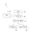
- the control block diagram which shows the structure of the periphery monitoring apparatus of the dump truck of FIG.
- the perspective view which shows arrangement
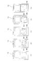
- the schematic diagram which shows the suspension cylinder etc. which were mounted in the dump truck of FIG. (A) is a figure which shows the state without a load on the bird's-eye view image displayed on the monitor screen of FIG. (B) is a figure which shows the state with a load.
- the flowchart which shows the flow of the load amount display control by the periphery monitoring apparatus of FIG. (A)-(e) is a figure which shows the change of the loading capacity in steps by the loading capacity display apparatus of the dump truck which concerns on other embodiment of this invention.
- a dump truck load display device will be described with reference to FIGS.
- “front”, “rear”, “left”, and “right” mean directions that are based on the direction seen from the driver sitting in the driver's seat and facing the front, “Vehicle width direction” is synonymous with “left-right direction”.
- the dump truck 1 is a self-propelled super large work vehicle used for mining work or the like, and has a vehicle width exceeding about 5 m.
- the dump truck 1 mainly includes a body frame 2, a cab 3, a vessel (loading platform) 4, a pair of left and right front wheels 5 and a rear wheel 6, and a power supply pantograph (not shown).
- a base 7 and a periphery monitoring device (loading amount display device) 10 (see FIG. 2) for monitoring the periphery of the vehicle are provided. The configuration and operation of the periphery monitoring device 10 will be described in detail later.
- the vehicle body frame 2 supports a power mechanism such as a diesel engine and a transmission and other auxiliary machines (not shown).
- a pair of left and right front wheels 5 are supported on the front part of the body frame 2, and a pair of left and right rear wheels 6 are supported on the rear part.
- the vehicle body frame 2 includes a lower deck portion 2A provided on the side close to the ground and an upper deck portion 2B provided above the lower deck portion 2A.
- Two movable ladders 2C for getting on and off are provided between the lower deck portion 2A and the ground.
- an oblique ladder 2D is provided between the lower deck portion 2A and the upper deck portion 2B to go back and forth between the lower deck portion 2A and the upper deck portion 2B.
- a rail-like handrail for movement is fixed on the upper deck portion 2B along the outer peripheral portion of the upper deck portion 2B.
- the cab 3 has a ROPS (Roll-Over-Protection Structure) structure that is arranged on the upper deck portion 2B on the left side from the center in the vehicle width direction and is composed of four support columns.
- the driver travels in a state where the shoulder on the left side of the vehicle body can be easily confirmed, but it is necessary to move his head greatly in order to check the surroundings of the vehicle body.
- the upper deck portion 2B is provided with a plurality of side mirrors (not shown) in order to check the surroundings of the vehicle. Since these side mirrors are located away from the cab 3, the driver needs to move his / her head greatly when checking the surroundings using the side mirrors.
- a driver's seat In the cab 3, a driver's seat, a shift lever, a controller (display control unit) 20, a monitor (display unit) 50, a handle, an accelerator pedal, a brake pedal, and the like are provided.
- the controller 20 and the monitor 50 constitute a part of the periphery monitoring device 10 described later.
- the vessel 4 is a loading platform for loading heavy objects such as crushed stones, and is rotatably connected to the rear end portion of the vehicle body frame 2 via a rotation shaft 4a at the bottom of the rear side.
- the vessel 4 has an upright posture in which the front portion is rotated upward by an actuator such as a hydraulic cylinder 31 (see FIG. 4) to discharge the load, and a loading posture in which the front portion is positioned above the cab 3. And can be rotated within the range.
- the periphery monitoring device 10 is a device that monitors the presence or absence of obstacles existing around the dump truck 1, and as shown in FIG. 2, six cameras 11 to 16, a controller 20, and a payload meter ECU. (Detector) 21, pressure sensor 22, stroke sensor 23, and monitor 50 are provided.
- the six cameras 11 to 16 are attached to the outer peripheral portion of the dump truck 1 in order to acquire an image in a 360-degree range around the dump truck 1.
- Each of the cameras 11 to 16 has a visual field range of 120 degrees in the left-right direction (60 degrees left and right) and 96 degrees in the height direction.
- the front camera 11 is arranged at the lower part of the uppermost landing part of the oblique ladder 2D so as to face the front of the vehicle body.
- the imaging range of the front camera 11 is the front of the vehicle.
- the right-side first camera 12 is disposed in the vicinity of the right end portion of the front side surface of the upper deck portion 2B so as to face the vehicle body diagonally forward. And the imaging range of the right-side first camera 12 is diagonally forward right of the vehicle.
- the first camera 13 on the left side is disposed in a symmetrical position with the second camera 12, that is, in the vicinity of the left end portion of the front side surface of the upper deck portion 2B so as to face the left front of the vehicle body. And the imaging range of the left-side first camera 13 is diagonally forward left of the vehicle.
- the second camera 14 on the right side is disposed in the vicinity of the front end portion of the right side surface of the upper deck portion 2B so as to face obliquely rearward to the right side of the vehicle body. And the imaging range of the right side second camera 14 is diagonally right rear of the vehicle.
- the second camera 15 on the left side is arranged symmetrically with the fourth camera, that is, in the vicinity of the front end of the left side surface of the upper deck portion 2B so as to face the left rear of the vehicle body.
- the imaging range of the second camera 15 on the left side is diagonally left rear of the vehicle.
- the rear camera 16 is disposed near the rear end of the vehicle body frame 2 so as to face the rear of the vehicle body.
- the imaging range of the rear camera 16 is the rear of the vehicle.
- each of the six cameras 11 to 16 transmits image data corresponding to the captured image to the controller 20.
- Controller 20 As shown in FIG. 2, the controller 20 is connected to the cameras 11 to 16, the payload meter ECU 21, and the monitor 50.
- the controller 20 receives the captured images from the respective cameras 11 to 16, synthesizes the images in the respective imaging ranges captured by the respective cameras 11 to 16 after converting the viewpoint to infinity, and combines them as shown in FIG.
- An overhead image 200 as shown in a) is generated.
- controller 20 receives data relating to the weight of the currently loaded load from the payload meter ECU 21 and synthesizes the load image C on the overhead image 200 as shown in FIG. Display.
- the payload meter ECU 21 is connected to a pressure sensor 22 and a stroke sensor 23, and uses an in-vehicle load meter (payload) that measures load weight using data received from the pressure sensor 22 and the stroke sensor 23. Meter).
- the pressure sensor 22 and the stroke sensor 23 connected to the payload meter ECU 21 are provided in a suspension cylinder 32 that supports the vessel 4 from below as shown in FIG.
- the pressure applied to the suspension cylinder 32 is detected by the pressure sensor 22, and the stroke amount of the suspension cylinder 32 is detected by the stroke sensor 23, whereby the weight of the load loaded on the vessel 4 is calculated by the payload meter ECU 21. can do.
- the load amount display control based on the weight of the load calculated in the payload meter ECU 21 will be described in detail later.
- ⁇ Load display control> In the dump truck 1 of the present embodiment, the controller 20 displays the presence / absence of a load on the vessel 4 on the screen of the monitor 50 according to the flowchart shown in FIG.
- step S1 the controller 20 acquires captured images in the respective imaging ranges from the six cameras 11 to 16 installed on the outer periphery of the dump truck 1.
- step S2 the controller 20 converts the images acquired from the cameras 11 to 16 into viewpoints at infinity and synthesizes them to generate an overhead image 200 that covers the entire 360 ° circumference of the dump truck 1.
- step S3 the controller 20 acquires the weight (loading amount) of the load loaded on the vessel 4 from the payload meter ECU 21.
- the load weight data acquired from the payload meter ECU 21 is calculated in the payload meter ECU 21 based on the detection results of the pressure sensor 22 and the stroke sensor 23.
- step S4 the controller 20 determines whether or not the weight (loading amount) of the load acquired from the payload meter ECU 21 is larger than a predetermined threshold value. If the weight of the load is larger than the threshold value, the process proceeds to step S5. If the weight of the load is smaller than the threshold value, the process proceeds to step S6.
- step S5 the controller 20 determines that there is a load on the vessel 4 based on the determination result in step S4, and the load image C is displayed on the vessel image 4G as shown in FIG. 5B.
- the image 1G of the dump truck 1 is combined and displayed on the monitor 50.
- step S6 the controller 20 determines that there is no load on the vessel 4 based on the determination result in step S4, and as shown in FIG. 5A, the load image C is displayed on the vessel image 4G.
- the image 1G of the dump truck 1 that is not displayed is synthesized and displayed on the monitor 50.
- the driver in the cab 3 can intuitively determine the current load depending on whether the image C of the load is displayed on the image 1G of the dump truck 1 displayed on the overhead view image 200 for monitoring the periphery.
- the presence or absence can be recognized. Therefore, the driver can be prevented from misinterpreting that there is a load even though it is in an empty state, or misunderstanding that it is in an empty state even though there is a load. .
- the size of the loaded image is divided into five levels as in the case of no loaded and loaded images C1 to C4. May be switched and displayed.
- the payload meter ECU 21 has four levels of threshold values, and when a loaded weight exceeding these threshold values is detected, the loaded images C1 to C4 at the levels corresponding to the threshold values are displayed. Are combined and displayed. In this case, the driver can intuitively recognize not only the presence / absence of the load but also the load amount of the load.
- the dump truck image is displayed in yellow or orange warning color according to the actual body color
- the cargo image is brown (soil) or gray (stone) etc. according to the actual load color
- it is preferable to display it in an easy-to-understand manner for the driver by coloring the image, for example, by displaying it in a different color.
- the cargo image may be displayed in a warning color such as red, yellow, or orange so that the cargo image can be easily seen.
- the dump truck image and cargo image are not limited to the above colors, but can be set to warning colors (yellow, orange, red, etc.) that are easy for the driver to understand,
- the color may be set, or the image portion may be displayed so as to be easily recognized by the driver by means of blinking the image portion.
- the dump truck load amount display device has been described as an example provided as a partial function of the periphery monitoring device 10.
- the present invention is not limited to this.
- the periphery monitoring device and the load amount display device may be provided separately.
- a sensor, a camera, or the like that detects whether or not a dump truck is loaded may be used as the detection unit of the present invention.
- the load weight cannot be recognized, the size of the load image cannot be changed in stages, but at least whether or not there is a load can be recognized.
- operator can confirm the presence or absence of a load intuitively only by confirming a monitor screen.
- a dump truck image and a cargo image may be prepared separately, and whether to synthesize the cargo image on the dump truck image may be switched based on the detection result of the load amount.
- the load display device for a dump truck has the effect of being able to intuitively recognize the state of the load on the loading platform simply by checking the monitor for the periphery monitoring. It can be widely applied to various construction machines.
Landscapes
- Engineering & Computer Science (AREA)
- Multimedia (AREA)
- Mechanical Engineering (AREA)
- Signal Processing (AREA)
- Transportation (AREA)
- Closed-Circuit Television Systems (AREA)
- Component Parts Of Construction Machinery (AREA)
- Traffic Control Systems (AREA)
Abstract
Description
すなわち、上記公報に開示された積荷重量計測装置では、空荷荷重を確実に計測することができるものの、モニタに数値として表示されるだけであるため、キャブ内の運転者が積荷の状態を直感的に認識することが困難である。
本発明の課題は、周辺監視用のモニタ画面を用いて、運転者に直感的に積荷状態を認識させることが可能なダンプトラックの積載量表示装置を提供することにある。
これにより、運転者は、モニタ画面を見ながら、荷台上にどの程度の積載量であるかを容易に認識することができる。
なお、積荷のイメージ部分に加えて、ダンプトラックの車体部分を着色して表示することで、積荷のイメージ部分との着色のコントラストをつけて、運転者が車両の積載状態をより分かり易くすることができる。
ここでは、積載量を検知する検知部として、ペイロードメータを用いている。
これにより、荷台上に載せられた積荷の重量を容易に検知することができる。
これにより、積荷の重量を直接的に受けるサスペンションシリンダにペイロードメータを設けることで、容易に積載量を検知することができる。
なお、以下の説明において、「前」「後」「左」「右」とは、運転席に着座して正面を向いている運転者から見た方向を基準とする方向を意味しており、「車幅方向」とは、「左右方向」と同義である。
本実施形態に係るダンプトラック1は、鉱山作業などに用いられる自走式の超大型作業車両であって、約5mを超える車幅を有している。
周辺監視装置10は、ダンプトラック1の周辺に存在する障害物の有無等を監視する装置であって、図2に示すように、6台のカメラ11~16と、コントローラ20と、ペイロードメータECU(検知部)21と、圧力センサ22と、ストロークセンサ23と、モニタ50と、を有している。
6台のカメラ11~16は、図3に示すように、ダンプトラック1の周囲360度範囲の画像を取得するためにダンプトラック1の外周部分にそれぞれ取り付けられている。なお、各カメラ11~16は、左右方向において120度(左右60度ずつ)、高さ方向において96度の視野範囲を有している。
以上の6台のカメラ11~16によれば、図5(a)に示すように、ダンプトラック1の周囲360度の全周囲を含む俯瞰画像200を取得することができる。また、6台のカメラ11~16は、それぞれ撮像した画像に対応する画像データをコントローラ20に送信する。
コントローラ20は、図2に示すように、各カメラ11~16、ペイロードメータECU21、モニタ50に接続されている。
ペイロードメータECU21は、図2に示すように、圧力センサ22およびストロークセンサ23に接続されており、圧力センサ22およびストロークセンサ23から受信したデータを用いて積載重量を計測する車載型荷重計(ペイロードメータ)として機能する。
なお、ペイロードメータECU21において算出された積荷の重量に基づく積載量表示制御については、後段にて詳述する。
本実施形態のダンプトラック1では、コントローラ20によって、図6に示すフローチャートに従って、モニタ50の画面上にベッセル4上の積荷の有無が表示される。
以上、本発明の一実施形態について説明したが、本発明は上記実施形態に限定されるものではなく、発明の要旨を逸脱しない範囲で種々の変更が可能である。
上記実施形態では、ダンプトラック1の荷台上の積荷の重量の検知結果に応じて、積荷がない状態(未積載状態)と積荷がある状態(積載状態)とを切り換える例を挙げて説明した。しかし、本発明はこれに限定されるものではない。
この場合には、運転者は、積荷の有無だけでなく、積荷の積載量まで直感的に認識することができる。
上記実施形態では、ダンプトラック1の荷台上の積荷の重量の検知結果に応じて、単に、積荷がない状態(未積載状態)と積荷がある状態(積載状態)とを切り換える例を挙げて説明した。しかし、本発明はこれに限定されるものではない。
なお、ダンプトラックの画像および積荷の画像については、上記色に限定されるものではなく、適宜、運転者が分かり易い警告色(黄、橙、赤等)に設定したり、運転者の好みで色を設定したりしてもよいし、画像部分を点滅させる等の手段によって運転者が認識し易いように表示してもよい。
上記実施形態では、本発明に係るダンプトラックの積載量表示装置が、周辺監視装置10の一部の機能として設けられている例を挙げて説明した。しかし、本発明はこれに限定されるものではない。
例えば、周辺監視装置と積載量表示装置とが別々に設けられていてもよい。
上記実施形態では、ダンプトラック1の積載量を検知する検知部として、ベッセル4に積載された積荷の重量を検知するペイロードメータECU21を用いた例を挙げて説明した。しかし、本発明はこれに限定されるものではない。
この場合には、積載重量を認識できないため段階的な積荷イメージの大きさの変更制御はできないものの、少なくとも積荷がある状態かない状態かについては認識することができる。このため、上記実施形態のように、積荷の有無を俯瞰画像上に表示することができるため、運転者は、モニタ画面を確認するだけで直感的に積荷の有無を確認することができる。
上記実施形態では、ペイロードメータECU21における検知結果に基づいて、積荷画像Cを含むダンプトラック1の画像1Gと、積荷画像Cを含まないダンプトラック1の画像1Gとを切り換えて表示する例を挙げて説明した。しかし、本発明はこれに限定されるものではない。
1G ダンプトラックの画像
2 車体フレーム
2A ロアデッキ部
2B アッパデッキ部
2C 可動式ラダー
2D 斜めラダー
3 キャブ
4 ベッセル
4G ベッセル画像
5 前輪
6 後輪
7 ベース
10 周辺監視装置(積載量表示装置)
11 前方カメラ
12 右側方第1カメラ
13 左側方第1カメラ
14 右側方第2カメラ
15 左側方第2カメラ
16 後方カメラ
20 コントローラ(表示制御部)
21 ペイロードメータECU(検知部)
22 圧力センサ(ペイロードメータ)
23 ストロークセンサ(ペイロードメータ)
31 油圧シリンダ
32 サスペンションシリンダ
50 モニタ(表示部)
200 俯瞰画像
C,C1~C4 積荷画像
Claims (5)
- 複数のカメラが搭載されており、前記複数のカメラによって得られる画像を組み合わせた俯瞰画像を用いて周辺監視を行うダンプトラックの積載量表示装置であって、
前記ダンプトラックの画像を含む前記俯瞰画像を表示する表示部と、
前記ダンプトラックの積載量を検知する検知部と、
前記検知部における検知結果に基づいて、前記ダンプトラックの荷台上に画像表示される積荷イメージの大きさを切り換えて前記表示部に表示させる表示制御部と、
を備えているダンプトラックの積載量表示装置。 - 前記表示制御部は、前記検知部における検知結果に応じて、前記積荷イメージの大きさを段階的に切り換える、
請求項1に記載のダンプトラックの積載量表示装置。 - 前記表示制御部は、前記ダンプトラックに荷台上に画像表示される前記積荷のイメージを、前記ダンプトラックの画像とは異なる色に着色して表示させる、
請求項1または2に記載のダンプトラックの積載量表示装置。 - 前記検知部は、前記荷台に積載された積荷の重量を測定するペイロードメータである、
請求項1または2に記載のダンプトラックの積載量表示装置。 - 前記ペイロードメータは、前記荷台を下方から支持するサスペンションシリンダに取付けられている、
請求項4に記載のダンプトラックの積載量表示装置。
Priority Applications (4)
| Application Number | Priority Date | Filing Date | Title |
|---|---|---|---|
| US13/811,475 US9204106B2 (en) | 2011-06-07 | 2012-05-23 | Load display device for dump truck |
| CA2805370A CA2805370C (en) | 2011-06-07 | 2012-05-23 | Load display device for dump truck |
| CN2012800021897A CN103026186A (zh) | 2011-06-07 | 2012-05-23 | 自卸车的装载量显示装置 |
| AU2012268482A AU2012268482A1 (en) | 2011-06-07 | 2012-05-23 | Device for displaying load quantity of dump truck |
Applications Claiming Priority (2)
| Application Number | Priority Date | Filing Date | Title |
|---|---|---|---|
| JP2011127225A JP5575703B2 (ja) | 2011-06-07 | 2011-06-07 | ダンプトラックの積載量表示装置 |
| JP2011-127225 | 2011-06-07 |
Publications (1)
| Publication Number | Publication Date |
|---|---|
| WO2012169358A1 true WO2012169358A1 (ja) | 2012-12-13 |
Family
ID=47295926
Family Applications (1)
| Application Number | Title | Priority Date | Filing Date |
|---|---|---|---|
| PCT/JP2012/063228 Ceased WO2012169358A1 (ja) | 2011-06-07 | 2012-05-23 | ダンプトラックの積載量表示装置 |
Country Status (6)
| Country | Link |
|---|---|
| US (1) | US9204106B2 (ja) |
| JP (1) | JP5575703B2 (ja) |
| CN (1) | CN103026186A (ja) |
| AU (1) | AU2012268482A1 (ja) |
| CA (1) | CA2805370C (ja) |
| WO (1) | WO2012169358A1 (ja) |
Cited By (4)
| Publication number | Priority date | Publication date | Assignee | Title |
|---|---|---|---|---|
| US8700274B1 (en) | 2013-04-26 | 2014-04-15 | Caterpillar Inc. | Method of determining when a bed of a hauling machine is empty |
| US8903612B2 (en) | 2013-04-26 | 2014-12-02 | Caterpillar Inc. | Method of determining when a payload loading event is occurring in a hauling machine |
| JP2015193273A (ja) * | 2014-03-31 | 2015-11-05 | 日立建機株式会社 | 建設機械の荷重計測装置 |
| US10094704B2 (en) | 2015-10-30 | 2018-10-09 | Caterpillar Inc. | System for estimating a mass of a payload in a hauling machine |
Families Citing this family (20)
| Publication number | Priority date | Publication date | Assignee | Title |
|---|---|---|---|---|
| JP5687130B2 (ja) * | 2011-05-10 | 2015-03-18 | 株式会社小松製作所 | 消耗材の自動供給システム |
| DE102013214368A1 (de) | 2013-07-23 | 2015-01-29 | Application Solutions (Electronics and Vision) Ltd. | Verfahren und Vorrichtung zur Wiedergabe eines seitlichen und/oder rückwärtigen Umgebungsbereichs eines Fahrzeugs |
| DE102013012314B4 (de) * | 2013-07-25 | 2015-07-30 | Knorr-Bremse Systeme für Nutzfahrzeuge GmbH | Verwendung einer fahrzeugfesten Bilderfassungs- und Analysevorrichtung zur Erfassung einer Beladungshöhe einer Beladung des Fahrzeugs |
| JP6243687B2 (ja) * | 2013-09-30 | 2017-12-06 | 株式会社小松製作所 | 運搬機械 |
| DE102013226104A1 (de) * | 2013-12-16 | 2015-06-18 | Application Solutions (Electronics and Vision) Ltd. | Verfahren und vorrichtung zur überwachung einer äusseren abmessung eines fahrzeugs |
| JP6235507B2 (ja) * | 2015-03-12 | 2017-11-22 | 日立建機株式会社 | 運搬車両の荷下ろし作業判定装置 |
| EP3306283B1 (en) * | 2015-05-26 | 2020-12-23 | Hitachi Construction Machinery Co., Ltd | Load measuring device for construction machine |
| CN105182956A (zh) * | 2015-07-29 | 2015-12-23 | 芜湖莫森泰克汽车科技有限公司 | 一种用于天窗ecu的安全监控系统 |
| JP6480830B2 (ja) * | 2015-08-24 | 2019-03-13 | 株式会社小松製作所 | ホイールローダの制御システム、その制御方法およびホイールローダの制御方法 |
| JP1559005S (ja) * | 2016-03-15 | 2016-09-20 | ||
| US9796267B1 (en) | 2016-06-03 | 2017-10-24 | Caterpillar Inc. | Machine operation assistance based on height detection of machine load using a camera |
| US20160281333A1 (en) * | 2016-06-07 | 2016-09-29 | Caterpillar Inc. | Work cycle monitoring system |
| US20160289927A1 (en) * | 2016-06-14 | 2016-10-06 | Caterpillar Inc. | Bowl monitoring system |
| JP7175680B2 (ja) * | 2018-08-31 | 2022-11-21 | 株式会社小松製作所 | 表示制御装置、表示制御システム、および表示制御方法 |
| US10857941B2 (en) * | 2019-01-28 | 2020-12-08 | Toyota Motor Engineering & Manufacturing North America, Inc. | E-mirror automatic position adjustment system |
| JP7177527B2 (ja) * | 2021-04-02 | 2022-11-24 | 株式会社住野事務所 | 移動式篩別車 |
| CN114932852B (zh) * | 2022-05-31 | 2023-05-09 | 吉林大学 | 一种矿用自卸车车架均载装置及其均载控制方法 |
| CA3206415A1 (en) | 2022-10-31 | 2024-04-30 | Agco Corporation | A volume determination system, a vehicle having a volume determination system, and methods of operating such a vehicle |
| CN117549813A (zh) * | 2023-11-21 | 2024-02-13 | 蒙阴县鹏程万里车辆有限公司 | 一种半挂车侧卸装置 |
| EP4585433A1 (en) * | 2024-01-09 | 2025-07-16 | Volvo Construction Equipment AB | Fluid-based suspension system of a vehicle |
Citations (4)
| Publication number | Priority date | Publication date | Assignee | Title |
|---|---|---|---|---|
| JP2001071809A (ja) * | 1999-09-07 | 2001-03-21 | Yazaki Corp | 車両用積載状態表示装置 |
| JP2006112796A (ja) * | 2004-10-12 | 2006-04-27 | Hitachi Constr Mach Co Ltd | 車両の積荷重量計測装置 |
| JP2009239754A (ja) * | 2008-03-27 | 2009-10-15 | Sanyo Electric Co Ltd | 画像処理装置、画像処理プログラム、画像処理システム及び画像処理方法 |
| JP2009292254A (ja) * | 2008-06-04 | 2009-12-17 | Sanyo Electric Co Ltd | 車両操作システム及び車両操作方法 |
Family Cites Families (4)
| Publication number | Priority date | Publication date | Assignee | Title |
|---|---|---|---|---|
| JPS6134425A (ja) * | 1984-07-27 | 1986-02-18 | Komatsu Ltd | ダンプトラツクの積載重量測定方法 |
| US5817989A (en) * | 1994-11-07 | 1998-10-06 | Yazaki Corporation | Vehicle-load-weight display system |
| US7395184B2 (en) * | 2004-01-15 | 2008-07-01 | Komatsu, Ltd. | Loaded weight measurement method and loaded weight measurement device for dump truck |
| JP2010093605A (ja) * | 2008-10-09 | 2010-04-22 | Sanyo Electric Co Ltd | 操縦支援装置 |
-
2011
- 2011-06-07 JP JP2011127225A patent/JP5575703B2/ja not_active Expired - Fee Related
-
2012
- 2012-05-23 US US13/811,475 patent/US9204106B2/en active Active
- 2012-05-23 WO PCT/JP2012/063228 patent/WO2012169358A1/ja not_active Ceased
- 2012-05-23 AU AU2012268482A patent/AU2012268482A1/en not_active Abandoned
- 2012-05-23 CN CN2012800021897A patent/CN103026186A/zh active Pending
- 2012-05-23 CA CA2805370A patent/CA2805370C/en active Active
Patent Citations (4)
| Publication number | Priority date | Publication date | Assignee | Title |
|---|---|---|---|---|
| JP2001071809A (ja) * | 1999-09-07 | 2001-03-21 | Yazaki Corp | 車両用積載状態表示装置 |
| JP2006112796A (ja) * | 2004-10-12 | 2006-04-27 | Hitachi Constr Mach Co Ltd | 車両の積荷重量計測装置 |
| JP2009239754A (ja) * | 2008-03-27 | 2009-10-15 | Sanyo Electric Co Ltd | 画像処理装置、画像処理プログラム、画像処理システム及び画像処理方法 |
| JP2009292254A (ja) * | 2008-06-04 | 2009-12-17 | Sanyo Electric Co Ltd | 車両操作システム及び車両操作方法 |
Cited By (4)
| Publication number | Priority date | Publication date | Assignee | Title |
|---|---|---|---|---|
| US8700274B1 (en) | 2013-04-26 | 2014-04-15 | Caterpillar Inc. | Method of determining when a bed of a hauling machine is empty |
| US8903612B2 (en) | 2013-04-26 | 2014-12-02 | Caterpillar Inc. | Method of determining when a payload loading event is occurring in a hauling machine |
| JP2015193273A (ja) * | 2014-03-31 | 2015-11-05 | 日立建機株式会社 | 建設機械の荷重計測装置 |
| US10094704B2 (en) | 2015-10-30 | 2018-10-09 | Caterpillar Inc. | System for estimating a mass of a payload in a hauling machine |
Also Published As
| Publication number | Publication date |
|---|---|
| CA2805370C (en) | 2016-01-19 |
| CA2805370A1 (en) | 2012-12-13 |
| AU2012268482A1 (en) | 2013-01-31 |
| US9204106B2 (en) | 2015-12-01 |
| CN103026186A (zh) | 2013-04-03 |
| US20130120579A1 (en) | 2013-05-16 |
| JP2012250694A (ja) | 2012-12-20 |
| JP5575703B2 (ja) | 2014-08-20 |
Similar Documents
| Publication | Publication Date | Title |
|---|---|---|
| JP5575703B2 (ja) | ダンプトラックの積載量表示装置 | |
| CA2808260C (en) | Work vehicle periphery monitoring apparatus | |
| CA2807166C (en) | Work vehicle periphery monitoring apparatus | |
| CN103828352B (zh) | 作业车辆用周边监视系统及作业车辆 | |
| CN103828353B (zh) | 自卸汽车用周边监视系统以及自卸汽车 | |
| AU2012268483B2 (en) | Dump truck | |
| US20140347483A1 (en) | Work vehicle periphery monitoring system and work vehicle | |
| AU2013218883A1 (en) | Periphery monitoring device for transportation vehicle | |
| CA2809654A1 (en) | Dump truck with obstacle detection mechanism and method for detecting obstacle | |
| JP6012680B2 (ja) | ダンプトラック | |
| CA2817869C (en) | Work vehicle periphery monitoring system and work vehicle |
Legal Events
| Date | Code | Title | Description |
|---|---|---|---|
| WWE | Wipo information: entry into national phase |
Ref document number: 201280002189.7 Country of ref document: CN |
|
| ENP | Entry into the national phase |
Ref document number: 2805370 Country of ref document: CA |
|
| WWE | Wipo information: entry into national phase |
Ref document number: 13811475 Country of ref document: US |
|
| ENP | Entry into the national phase |
Ref document number: 2012268482 Country of ref document: AU Date of ref document: 20120523 Kind code of ref document: A |
|
| 121 | Ep: the epo has been informed by wipo that ep was designated in this application |
Ref document number: 12796966 Country of ref document: EP Kind code of ref document: A1 |
|
| NENP | Non-entry into the national phase |
Ref country code: DE |
|
| 122 | Ep: pct application non-entry in european phase |
Ref document number: 12796966 Country of ref document: EP Kind code of ref document: A1 |