WO2012169280A1 - トイレ設備 - Google Patents
トイレ設備 Download PDFInfo
- Publication number
- WO2012169280A1 WO2012169280A1 PCT/JP2012/059575 JP2012059575W WO2012169280A1 WO 2012169280 A1 WO2012169280 A1 WO 2012169280A1 JP 2012059575 W JP2012059575 W JP 2012059575W WO 2012169280 A1 WO2012169280 A1 WO 2012169280A1
- Authority
- WO
- WIPO (PCT)
- Prior art keywords
- toilet
- amount
- water
- treatment
- processing
- Prior art date
- Legal status (The legal status is an assumption and is not a legal conclusion. Google has not performed a legal analysis and makes no representation as to the accuracy of the status listed.)
- Ceased
Links
Images

Classifications
-
- A—HUMAN NECESSITIES
- A47—FURNITURE; DOMESTIC ARTICLES OR APPLIANCES; COFFEE MILLS; SPICE MILLS; SUCTION CLEANERS IN GENERAL
- A47K—SANITARY EQUIPMENT; ACCESSORIES THEREFOR, e.g. TOILET ACCESSORIES
- A47K11/00—Closets without flushing; Urinals without flushing; Chamber pots; Chairs with toilet conveniences or specially adapted for use with toilets
- A47K11/02—Dry closets, e.g. incinerator closets
-
- E—FIXED CONSTRUCTIONS
- E03—WATER SUPPLY; SEWERAGE
- E03D—WATER-CLOSETS OR URINALS WITH FLUSHING DEVICES; FLUSHING VALVES THEREFOR
- E03D11/00—Other component parts of water-closets, e.g. noise-reducing means in the flushing system, flushing pipes mounted in the bowl, seals for the bowl outlet, devices preventing overflow of the bowl contents; devices forming a water seal in the bowl after flushing, devices eliminating obstructions in the bowl outlet or preventing backflow of water and excrements from the waterpipe
- E03D11/02—Water-closet bowls ; Bowls with a double odour seal optionally with provisions for a good siphonic action; siphons as part of the bowl
- E03D11/10—Bowls with closure elements provided between bottom or outlet and the outlet pipe; Bowls with pivotally supported inserts
-
- Y—GENERAL TAGGING OF NEW TECHNOLOGICAL DEVELOPMENTS; GENERAL TAGGING OF CROSS-SECTIONAL TECHNOLOGIES SPANNING OVER SEVERAL SECTIONS OF THE IPC; TECHNICAL SUBJECTS COVERED BY FORMER USPC CROSS-REFERENCE ART COLLECTIONS [XRACs] AND DIGESTS
- Y02—TECHNOLOGIES OR APPLICATIONS FOR MITIGATION OR ADAPTATION AGAINST CLIMATE CHANGE
- Y02A—TECHNOLOGIES FOR ADAPTATION TO CLIMATE CHANGE
- Y02A50/00—TECHNOLOGIES FOR ADAPTATION TO CLIMATE CHANGE in human health protection, e.g. against extreme weather
- Y02A50/30—Against vector-borne diseases, e.g. mosquito-borne, fly-borne, tick-borne or waterborne diseases whose impact is exacerbated by climate change
Definitions
- the present invention relates to toilet facilities.
- Patent Document 1 discloses a conventional toilet facility.
- This toilet facility includes a toilet body, a discharge path, a treatment tank, and a stirring device.
- the toilet bowl body has a toilet bowl.
- the discharge channel communicates with the toilet bowl and extends downward.
- the treatment tank communicates with the lower end of the discharge path and is disposed below the toilet body.
- this processing tank stores the processing material which decomposes manure.
- the treatment material is sawdust carrying aerobic degrading bacteria.
- the stirrer has a screw arranged in the treatment tank. By rotating this screw, the processing material accommodated in the processing tank can be stirred.
- This toilet equipment agitates the processing material by rotating the screw of the agitator at regular intervals. This makes it possible to evaporate the water content of the treatment material or to supply oxygen to the aerobic bacteria of the treatment material. For this reason, this toilet equipment can accelerate
- Patent Document 1 stirs the treatment material by rotating the screw of the stirrer at regular intervals regardless of the amount of manure or the like entering the treatment tank. For this reason, there exists a possibility that a processing material may be in an excessive moisture state or an excessively dry state depending on the amount of moisture entering the treatment tank. If the treatment material becomes excessively watery or excessively dry, the activity of the aerobic degrading bacteria is weakened and the decomposition of manure may be insufficient. In particular, when a flush toilet that uses toilet flushing water or a local washing device is used for toilet equipment, toilet flushing water or local washing water flows into the treatment tank, and the treatment material contains excessive moisture. Prone to state. If the treatment material becomes excessively watery, the activity of the aerobic degrading bacteria is weakened, and there is a possibility that the decomposition of manure is insufficient.
- the present invention has been made in view of the above-described conventional situation, and an object to be solved is to provide a toilet facility capable of satisfactorily decomposing human waste.
- the toilet facility of the first invention comprises a toilet bowl body, A toilet bowl cleaning device for supplying toilet flushing water to the toilet body, A treatment tank for storing treatment material that is introduced through the toilet body, and containing a treatment material for decomposing this waste material; Toilet equipment provided with a treatment device that promotes decomposition of manure by the treatment material, A control device is provided for controlling the operating conditions of the processing device in accordance with the amount of toilet flushing water entering the processing tank.
- this toilet equipment is equipped with a control device that prevents the treatment material stored in the treatment tank from becoming excessively dry or overdried. Operating conditions can be controlled. In other words, this toilet equipment operates the treatment device so that moisture easily evaporates from the treatment material as the amount of toilet flush water entering the treatment tank increases, preventing the treatment material from becoming excessively watery. can do. In addition, when the amount of toilet flushing water entering the treatment tank is small, this toilet equipment operates the treatment device so that the water does not evaporate from the treatment material, preventing the treatment material from becoming overdried. can do. Thus, this toilet facility can maintain a state in which the treatment material can satisfactorily decompose manure.
- the toilet facility according to the first invention can satisfactorily decompose urine.
- the toilet equipment of the second invention is a local cleaning device for discharging local cleaning water;
- Toilet equipment provided with a treatment device that promotes decomposition of manure by the treatment material,
- a control device is provided for controlling operating conditions of the processing device in accordance with the amount of the local cleaning water entering the processing tank.
- this toilet equipment is equipped with a control device that prevents the treatment material stored in the treatment tank from becoming excessively dry or overdried. Operating conditions can be controlled. In other words, this toilet equipment operates the treatment device so that moisture easily evaporates from the treatment material as the amount of local wash water entering the treatment tank increases, and prevents the treatment material from becoming excessively watery. can do. In addition, when the amount of local wash water entering the treatment tank is small, this toilet equipment operates the treatment tank so that the water does not evaporate from the treatment material, and prevents the treatment material from being overdried. can do. Thus, this toilet facility can maintain a state in which the treatment material can satisfactorily decompose manure.
- the toilet equipment of the second invention can satisfactorily decompose urine.
- a toilet facility is a treatment tank for storing a treatment material for decomposing human waste, Toilet equipment provided with a treatment device that promotes decomposition of manure by the treatment material, A control device is provided for controlling operating conditions of the processing device in accordance with the amount of manure entering the processing tank.
- the control device operates the processing device so that the processing material stored in the processing tank does not become excessively watery or overdried according to the amount of manure entering the processing tank.
- Conditions can be controlled.
- this toilet facility increases the amount of water in the treatment tank as the amount of manure that enters the treatment tank increases. Therefore, the toilet equipment is operated so that the water easily evaporates from the treatment material. Excessive moisture can be prevented.
- the toilet equipment operates the treatment device so that the moisture does not evaporate from the treatment material, and the treatment material becomes overdried. This can be prevented.
- this toilet facility can maintain a state in which the treatment material can satisfactorily decompose manure.
- the toilet equipment of the third invention can satisfactorily decompose urine.
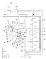
- FIG. 1 It is the schematic which shows the toilet installation of Example 1.
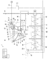
- FIG. 2 It is the schematic which shows the toilet installation of Example 2.
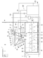
- FIG. 2 It is the schematic which shows the toilet installation of Example 3.
- FIG. 2 It is the schematic which shows the toilet installation of Example 4.
- FIG. 1 It is the schematic which shows the toilet installation of Example 1.
- cleaning apparatus is assembled
- the user of the toilet facility can use the toilet body. For this reason, a user can utilize a toilet equipment favorably.
- the toilet bowl body connected to the said processing tank can be provided.
- the user of the toilet facility can use the toilet body.
- a user can utilize a toilet equipment favorably.
- the treatment apparatus of the first to third inventions is an agitation device for agitating the treatment material stored in the treatment tank, and the control device can control the agitation operation of the agitation device.
- this toilet facility increases the amount of stirring, such as extending the driving time of the stirring device. As a result, it is possible to easily evaporate the moisture from the treatment material, and to prevent the treatment material from being excessively moist.
- this toilet facility reduces the amount of stirring, such as shortening the drive time of the stirring device. Thereby, it can prevent that a processing material will be in an overdried state. Thus, this toilet facility can maintain a state in which the treatment material can satisfactorily decompose manure.
- the processing apparatus of the first to third inventions is a heating apparatus for heating the processing material stored in the processing tank, and the control apparatus can control the temperature of the heating apparatus.
- this toilet equipment raises the temperature of the heating device when the amount of water in the treatment tank is large. As a result, it is possible to easily evaporate the moisture from the treatment material, and to prevent the treatment material from being excessively moist.
- this toilet equipment makes the temperature of a heating apparatus low, when there is little water content in a processing tank. Thereby, it can prevent that a processing material will be in an overdried state. Thus, this toilet facility can maintain a state in which the treatment material can satisfactorily decompose manure.
- the treatment apparatus of the first to third inventions is an exhaust device that exhausts the air in the treatment tank to the outside, and the control device can control the exhaust operation of the exhaust device.
- this toilet facility increases the exhaust amount of the exhaust device when the amount of water in the treatment tank is large. As a result, it is possible to easily evaporate the moisture from the treatment material, and to prevent the treatment material from being excessively moist. Further, this toilet facility reduces the exhaust amount of the exhaust device when the amount of water in the treatment tank is small. Thereby, it can prevent that a processing material will be in an overdried state. Thus, this toilet facility can maintain a state in which the treatment material can satisfactorily decompose manure.
- the amount of toilet flush water, the amount of local wash water, and / or the amount of excreta entering the treatment tank may be a cumulative amount within a set time.
- this toilet facility can properly grasp the amount of water in the treatment tank. That is, it is not affected by the amount of toilet flushing water that changes during the set time. For this reason, this toilet equipment can grasp
- the control device includes: the toilet cleaning device, the local cleaning device, and / or the amount of the toilet cleaning water that enters the treatment tank from the usage status of the toilet body, the amount of the local cleaning water, and / or the urine The amount can be inferred.
- this toilet equipment detects the number of times of use and / or the time of use, etc., using various sensors provided in the toilet bowl cleaning device, the local cleaning apparatus, or the toilet bowl body. Thereby, this toilet equipment grasps the use situation of the toilet bowl cleaning device, the local cleaning device, or the toilet body.
- this toilet equipment is the number of times of use and / or use time of the toilet cleaning device, the local cleaning device, or the toilet main body, the amount of toilet cleaning water entering the treatment tank, the amount of local cleaning water, and / or the amount of urine. From analogy. For this reason, this toilet facility can be inferred without directly measuring the amount of toilet flush water, the amount of local wash water, and / or the amount of urine that enters the treatment tank.
- a discharge path extending in the vertical direction communicating the toilet body and the processing tank, and a flapper member for opening and closing the discharge path,
- the control device can infer the amount of the toilet flushing water entering the processing tank, the amount of the local washing water, and / or the amount of manure from the number of times the flapper member is opened and closed.
- this toilet facility analogizes the amount of toilet flush water, the amount of local wash water, and / or the amount of urine that enters the treatment tank from the number of times the flapper member is opened and closed. For this reason, this toilet facility can be inferred without directly measuring the amount of toilet flush water, the amount of local wash water, and / or the amount of urine that enters the treatment tank.
- the toilet bowl cleaning device can perform large washing with a large amount of toilet flush water supplied to the toilet body and small washing with a small amount of water
- the control device can analogize the amount of toilet flushing water entering the treatment tank from the number of executions of the large washing and the small washing.
- this toilet facility estimates the amount of toilet flushing water entering the treatment tank from the number of large and small washings performed. For this reason, this toilet facility can be inferred without directly measuring the amount of toilet flush water entering the treatment tank.
- the toilet facility includes a toilet body 10, a toilet cleaning device 20, a local cleaning device 30, a discharge path 40, a treatment tank 50, a stirring device 60 that is a processing device, and a control device 70. I have.
- the toilet body 10 includes a toilet bowl 11.
- the toilet bowl 11 has a discharge port 11A penetrating in the vertical direction at the lowermost end.
- the toilet bowl 11 has connected the connection member 41 to the discharge port 11A.
- the connecting member 41 forms a discharge path 40 inside.
- the discharge path 40 communicates the discharge port 11 ⁇ / b> A and the treatment tank 50.
- the connecting member 41 has an inflow portion 42.
- the inflow portion 42 connects the upper end opening to the outer peripheral surface of the discharge port 11A.
- the inflow portion 42 has a mortar shape continuous from the upper end opening.
- the lower end of the inflow portion 42 is open.
- the connection member 41 has an intermediate pipe portion 43.
- the intermediate tube portion 43 is cylindrical.
- the intermediate pipe portion 43 has an inclined surface whose upper end portion is inclined obliquely upward from the inner peripheral surface toward the outer peripheral surface. This upper end opening edge is located outside and above the lower end opening edge of the inflow portion 42. Further, a gap is formed between the inclined surface at the upper end portion of the intermediate pipe portion 43 and the outer peripheral surface at the lower end portion of the inflow portion 42.
- the connecting member 41 has a connecting portion 44.
- the connecting portion 44 connects the upper portion of the outer surface of the inflow portion 42 and the outer surface of the intermediate tube portion 43.
- the connecting portion 44 has an air passage 45.
- the air passage 45 extends outward from a part of the outer surface of the connecting portion 44.
- the connecting member 41 has a discharge part 46.
- the discharge part 46 is connected to the outer peripheral surface of the intermediate pipe part 43.
- the lower end of the discharge part 46 is open.
- the lower end opening is connected to a through hole 51 provided in the floor F.
- the discharge part 46 has the closing tool 80 attached inside.
- the closing tool 80 includes a flapper member 81, a support member 82, and a weight member 83.
- the flapper member 81 is formed in a saucer shape having a disc-shaped central portion and an edge portion inclined continuously upward and obliquely outward from the outer peripheral edge portion thereof.
- the support member 82 supports the flapper member 81 at one end and connects a weight member 83 to the other end.
- the support member 82 is pivotally supported on the weight member 83 side so as to be rotatable.
- the weight of the weight member 83 is set so that the flapper member 81 is lowered when the flapper member 81 receives a manure or the like exceeding a set weight to open the discharge passage 40. When manure falls from the flapper member 81, the flapper member 81 rises and closes the discharge path 40.
- the air passage 45 is a gap formed between the inclined surface of the upper end portion of the connecting portion 44 and the intermediate tube portion 43 and the outer peripheral surface of the lower end portion of the inflow portion 42. And the stool 11 through the inflow part 42. Further, the air passage 45 communicates the tip portion with the upper portion of the processing tank.
- the toilet bowl cleaning device 20 includes a water supply channel 21, an on-off valve 22, a flow rate sensor S 1, and a rim discharge pipe 24.
- the on-off valve 22 is provided in the water supply channel 21.
- the flow rate sensor S ⁇ b> 1 can detect the flow rate of the cleaning water flowing through the water supply path 21.
- the rim water discharge pipe 24 can discharge toilet flushing water into a rim water passage formed at the periphery of the upper end portion of the toilet bowl 11.
- the water supply path 21 communicates the water pipe S and the rim water discharge pipe 24.
- the toilet bowl cleaning device 20 can be operated by a remote controller 1 attached to a wall surface W of a toilet room.
- the remote controller 1 has a large washing button (full flush button) and a small washing button (partial flush button).
- a valve opening signal corresponding to each button is transmitted from the remote controller 1 to the receiving unit 2.
- the receiving unit 2 opens the on-off valve 22 for each set time according to the received valve opening signal.
- the on-off valve 22 opens for a longer time than when the small washing button is pushed.
- the toilet bowl cleaning device 20 executes large washing with a large amount of toilet bowl washing water supplied from the rim water discharge pipe 24 to the toilet bowl 11.
- the toilet bowl cleaning device 20 executes small washing with a small amount of toilet bowl washing water supplied from the rim water discharge pipe 24 to the toilet bowl 11.
- the toilet flushing water supplied to the toilet bowl 11 of the toilet bowl main body 10 by the toilet flushing device 20 by executing the large washing or the small washing flows into the treatment tank 50 through the toilet bowl 11 and the discharge path 40.
- the local cleaning device 30 includes a local cleaning water supply channel 31, an on-off valve 32, a warm water tank 33, and a local cleaning nozzle 34.
- the local cleaning water supply channel 31 is formed by branching the water supply channel 21 downstream of the flow rate sensor S1.
- the on-off valve 32 is provided in the local cleaning water supply channel 31.
- the hot water tank 33 communicates with the downstream end of the local cleaning water supply channel 31.
- the local cleaning nozzle 34 communicates with the hot water tank 33.
- the local cleaning device 30 can be operated by the remote controller 1 attached to the wall surface W of the toilet room.
- the remote controller 1 has a local cleaning button and a stop button.
- a valve opening signal is transmitted from the remote controller 1 to the receiving unit 2.
- the receiving unit 2 opens the on-off valve 32.
- the local cleaning device 30 performs local cleaning by ejecting local cleaning water from the local cleaning nozzle 34 according to the cleaning strength set at that time.
- a valve closing signal is transmitted from the remote controller 1 to the receiving unit 2.
- the receiving part 2 will close the on-off valve 32, if a valve-closing signal is received.
- the local cleaning device 30 stops the ejection of the local cleaning water from the local cleaning nozzle 34 and ends the local cleaning. Due to the execution of the local cleaning, the local cleaning water discharged by the local cleaning device 30 flows into the treatment tank 50 through the toilet bowl 11 and the discharge path 40.
- the flow rate sensor S1 provided in the water supply channel 21 is used for the flow rate of the cleaning water flowing through the water supply channel 21 when the toilet cleaning device 20 performs the large cleaning and the small cleaning, and the local cleaning device 30 performs the local cleaning.
- the flow rate of the cleaning water flowing through the water supply channel 21 is detected. That is, the toilet bowl cleaning device 20 supplies the toilet bowl 11 of the toilet bowl body 10, the flow rate of toilet bowl washing water flowing into the treatment tank 50 through the toilet bowl 11 and the discharge path 40, and the local washing apparatus 30 discharges water.
- the flow rate of the local wash water flowing into the treatment tank 50 through the toilet bowl 11 and the discharge path 40 is detected.
- the flow sensor S1 transmits a flow signal to the control device 70 according to the detected flow rate. Based on the flow rate signal received from the flow rate sensor S1, the control device 70 stores the cumulative amount (water amount) of the cleaning water flowing through the water supply path 21 every set time (for example, 1 hour).
- the treatment tank 50 is disposed below the toilet body 10 and below the floor F.
- the processing tank 50 stores a processing material 90 that decomposes manure.
- the treatment material 90 is sawdust carrying aerobic degrading bacteria.
- the processing tank 50 has a heating device (heater 51) as a processing device arranged at the lower end.
- the heater 51 can heat the treatment material 90.
- the heater 51 can heat the treatment material 90 to evaporate the moisture in the treatment material 90 or to set the temperature at which the aerobic degrading bacteria of the treatment material 90 can easily act. For this reason, by controlling the temperature of the heater 51, the aerobic degrading bacteria of the treatment material 90 can be actively activated, and the decomposition of manure can be promoted.
- the treatment tank 50 is provided with an exhaust device (an exhaust fan 52) which is a treatment device.
- the exhaust fan 52 can exhaust the air in the processing tank 50 to the outside.
- the exhaust fan 52 can exhaust the moisture evaporated from the processing material 90 to the outside by exhausting the air in the processing tank 50 to the outside. For this reason, by controlling the exhaust operation of the exhaust fan 52, the aerobic decomposing bacteria of the treatment material 90 can be actively activated, and the decomposition of manure can be promoted.
- the exhaust fan 52 exhausts the air (odor) in the processing tank 50 to the outside, so that the odor in the toilet room is also generated through the processing tank 50, the air passage 45, the connection member 41, and the toilet bowl 11. Can be exhausted.
- the exhaust fan 52 can adjust the exhaust amount according to the presence or absence of a user in the toilet room detected by the human body detection sensor S2. Further, when the deodorizing button provided on the remote controller 1 is pressed, the exhaust fan 52 can increase the number of rotations and increase the exhaust amount. The temperature of the heater 51 and the exhaust amount of the exhaust fan 52 are controlled by the control device 70.
- the stirring device 60 is disposed in the treatment tank 50.
- the stirring device 60 includes a main shaft 61, a spiral wing-like stirring blade 62, and an agitation motor M.
- the main shaft 61 extends across the inner walls facing the processing tank 50.
- the stirring blade 62 is connected to the main shaft 61.
- the stirring motor M drives the main shaft 61 to rotate.
- the stirrer 60 rotates in both directions (forward rotation and reverse rotation) when the stirring motor M is driven to rotate, and can stir the treatment material 90.
- By stirring the treatment material 90 by the stirring device 60 it is possible to disperse the manure that has entered the treatment tank 50 in the treatment material 90 while facilitating the evaporation of the moisture in the treatment material 90. For this reason, the aerobic decomposing bacteria of the treatment material 90 are actively activated, and the decomposition of manure can be promoted.
- the operation pattern of the stirring motor M is controlled by the control device 70.
- the control device 70 is configured so that the cleaning water flowing in the water supply channel 21 every set time (1 hour) (the toilet flushing water entering the treatment tank 50 and the local portion).
- the agitation motor M, the heater 51, and the exhaust fan 52 are controlled during the subsequent set time (1 hour) according to the accumulated amount (water amount) of the washing water. That is, the controller 70 supplies the toilet bowl main body 10 to the toilet bowl main body 10, and the amount of toilet bowl washing water that enters the treatment tank 50 through the toilet bowl 11 and the discharge path 40, and the local washing apparatus 30 discharges water.
- the control device 70 controls the agitation motor M, the heater 51, and the exhaust fan 52 in accordance with the amount of the local washing water that enters the treatment tank 50 via the toilet bowl 11 and the discharge path 40.
- the rotation time (forward rotation, reverse rotation) of the stirring motor M becomes longer and the stop time becomes shorter. That is, the amount of stirring of the stirring device 60 increases.
- the set value of the heater 51 becomes higher as the cumulative amount (water amount) of the cleaning water flowing through the water supply passage 21 every set time (1 hour) increases.
- the exhaust amount of the exhaust fan 52 when there is no user in the toilet room increases.
- the cumulative amount (water amount) of the cleaning water flowing through the water supply channel 21 for each set time (one hour) increases. Increase the temperature of the heater 51 and increase the exhaust amount of the exhaust fan 52.
- the water contained in the treatment material 90 is easily evaporated, and the treatment material 90 is prevented from becoming excessively watery. Further, human waste is dispersed in the treatment agent 90 to facilitate decomposition.
- the cumulative amount (water amount) of the cleaning water flowing through the water supply channel 21 every set time (1 hour) is small, the amount of stirring of the stirrer 60 is decreased, the temperature of the heater 51 is lowered, and the exhaust fan 52 exhausts. Reduce the amount. This prevents the treatment material 90 from being overdried.
- Example 1 Therefore, the toilet facility of Example 1 can satisfactorily decompose urine.
- the exhaust amount of the exhaust fan 52 when the user is in the toilet room and the deodorizing operation is kept constant. This is because the exhaust fan 52 is driven mainly for exhausting the odor in the toilet room in order to make it difficult for the user to feel the odor. At this time, the exhaust amount of the exhaust fan 52 during the deodorization operation is increased because the user feels odor and the deodorization button of the remote controller 1 is pressed. It is for exhausting.
- the toilet facility of the second embodiment has a point that the flow rate sensor S ⁇ b> 1 is not provided in the water supply channel 21, and the control device 71 opens and closes the open / close state of the on-off valve 22 of the toilet flushing device 20 and the local washing
- the embodiment in that the amount of toilet flush water entering the treatment tank 50 and the amount of local wash water are estimated from the open / close status of the on / off valve 32 of the device 30, that is, the usage status of the toilet cleaning device 20 and the local cleaning device 30. 1 and different.
- Other configurations are the same as those of the first embodiment, and the same configurations are denoted by the same reference numerals and detailed description thereof is omitted.
- the toilet bowl cleaning apparatus 20 When the large washing button or the small washing button of the remote controller 1 is pressed, a corresponding valve opening signal is transmitted from the remote controller 1 to the receiving unit 3. The receiving unit 3 opens the on-off valve 22 for each set time according to the received valve opening signal.
- the toilet bowl cleaning apparatus 20 performs toilet bowl cleaning. That is, when the large washing button of the remote controller 1 is pressed, the toilet bowl washing device 20 executes large washing with a long opening time of the on-off valve 22.
- the small washing button of the remote controller 1 When the small washing button of the remote controller 1 is pressed, the toilet bowl cleaning device 20 executes small washing with a short opening time of the on-off valve 22.
- the toilet flushing device 20 controls the amount of water for large washing and small washing according to the opening time of the on-off valve 22, the toilet flushing device is actually used when the water supply pressure of the water pipe S fluctuates.
- the amount of toilet flushing water that 20 supplies to the toilet body 10 varies with the set amount of water. That is, the amount of toilet flushing water entering the processing tank 50 varies.
- the receiving unit 3 that has received the valve opening signal transmits a signal corresponding to the large washing or the small washing to the control device 71.
- the control device 71 can count and store a signal corresponding to the large washing or the small washing every set time (one hour). That is, the control device 71 stores the number of executions of large cleaning and the number of executions of small cleaning every set time (1 hour). Then, the control device 71 multiplies the number of executions of each of the large washing and the small washing by the set water amount for each of the large washing and the small washing.
- the control device 71 accumulates the amount of toilet flush water (water amount) supplied to the toilet body 10 by the toilet flushing device 20 every set time (one hour), that is, the accumulation of toilet flush water entering the treatment tank 50.
- the amount (water amount) can be inferred.
- the local cleaning device 30 performs local cleaning by ejecting local cleaning water at a flow rate corresponding to the cleaning strength set at that time from the local cleaning nozzle 34.
- the flow rate of the local cleaning water actually discharged by the local cleaning device 30 varies with respect to the set flow rate due to the fluctuation of the water supply pressure of the water pipe S. That is, the amount of local cleaning water entering the processing tank 50 varies.
- a valve closing signal is transmitted from the remote controller 1 to the receiving unit 3.
- the receiving unit 3 closes the on-off valve 32.
- the local cleaning device 30 finishes the ejection of the local cleaning water from the local cleaning nozzle 34 and ends the local cleaning.
- the receiving unit 3 transmits a valve opening signal, a valve closing signal, and a flow rate signal corresponding to the cleaning strength at that time to the control device 71.
- the control device 71 measures the time from the valve opening signal to the valve closing signal. Then, the control device 71 multiplies the measured time by a set flow rate corresponding to the flow rate signal. Accordingly, the control device 71 causes the accumulated amount (water amount) of the local cleaning water discharged by the local cleaning device 30 every set time (1 hour), that is, the accumulated amount (water amount) of the local cleaning water entering the processing tank 50. Can be analogized.
- the control device 71 sums up the accumulated amount (water amount) of toilet flushing water entering the treatment tank 50 and the accumulated amount (water amount) of local washing water every set time (1 hour). Can be remembered.
- the toilet flush water entering the processing tank 50 estimated by the set time (one hour) stored in the control device 71 and the local flush water are totaled.
- the controller 70 controls the stirring motor M, the heater 51, and the exhaust fan 52 during the subsequent set time (1 hour) according to the accumulated amount (water amount). That is, the controller 71 controls the agitation motor M, the heater 51, and the exhaust fan 52 in accordance with the estimated amount of toilet flush water entering the processing tank 50 and the amount of local wash water.
- the stirring amount of the stirring device 60 is increased, and the heater 51 And the exhaust amount of the exhaust fan 52 is increased.
- the water contained in the treatment material 90 is easily evaporated, and the treatment material 90 is prevented from becoming excessively watery. Further, human waste is dispersed in the treatment agent 90 to facilitate decomposition.
- the stirring amount of the stirring device 60 is reduced, The temperature of the heater 51 is lowered and the exhaust amount of the exhaust fan 52 is reduced. This prevents the treatment material 90 from being overdried.
- the toilet facility of Example 2 can also perform the decomposition of urine well.
- the toilet facility of the third embodiment has a lock mechanism (not shown) that locks the flapper member 81 in a state in which the toilet flushing device 100 reuses washing water and the discharge path 40 is closed.
- Other configurations are the same as those of the second embodiment, and the same configurations are denoted by the same reference numerals and detailed description thereof is omitted.
- the toilet bowl cleaning apparatus 100 includes a water supply channel 103 having a drainage channel 101, a water storage tank 102, and a pump P.
- the drainage channel 101 extends outward from a part of the outer surface of the connecting portion 44 of the connection member 41.
- the drainage channel 101 communicates with a water storage tank 102 that penetrates the wall surface W of the toilet room and is installed outdoors.
- the water storage tank 102 communicates with a water supply path 103 having a pump P.
- the water supply path 103 communicates with the rim water discharge pipe 24.
- the drainage channel 101 communicates an air channel 145 with the upstream portion.
- the toilet flushing apparatus 100 can perform toilet flushing by driving the pump P to supply toilet flushing water (medium water) stored in the water storage tank 102 from the rim water discharge pipe 24 to the toilet bowl 11.
- toilet flushing water medium water
- the lock mechanism locks the flapper member 81 while the toilet bowl cleaning device 100 is executing toilet cleaning or when the local cleaning apparatus 30 is executing local cleaning.
- the toilet flushing water or the local flushing water received by the flapper member 81 is applied to the inclined surface formed at the upper end portion of the intermediate pipe portion 43 of the connecting member 41 and the lower end portion of the inflow portion 42. It flows into the drainage channel 101 from a gap formed between the outer peripheral surface.
- the toilet flushing water that has flowed into the drainage channel 101 is stored in the water storage tank 102.
- the water storage tank 102 incorporates a filter member and a chlorine sterilizer, and stores toilet water and medium water purified from local washing water.
- cleaning apparatus 100 can reuse toilet bowl washing
- the water storage tank 102 communicates with the water pipe S. For this reason, when the amount of middle water stored in the water storage tank 102 is reduced, tap water can be supplied from the water pipe S into the water storage tank 102.
- the water level of toilet flushing water or the like stored on the upper surface of the flapper member 81 is set to be lower than the lower end of the inflow portion 42. For this reason, the toilet bowl 11 and the air path 145 are in communication with the flapper member 81 closing the discharge path 40. Further, since the air passage 145 communicates with the drainage passage 101, when the exhaust fan 52 is driven, the odor or the like in the toilet room can be exhausted using the drainage passage 101. If the level of the toilet flushing water or the like stored on the upper surface of the flapper member 81 becomes higher than the set water level, the flapper member 81 descends to open the discharge passage 40 and the toilet flushing water or the like falls into the treatment tank 50.
- the weight of the weight member 83 is set.
- the water level of the toilet flushing water or the like stored on the upper surface of the flapper member 81 does not rise from the inflow portion 42, the air in the toilet room is passed through the toilet bowl 11, the connecting member 41, the drainage channel 101, and the air channel 145. Can be reliably vented outdoors.
- the opening / closing sensor S3 transmits an opening signal to the receiving unit 4 when detecting that the flapper member 81 is lowered (the weight member 83 is raised) and the discharge path 40 is opened.
- the receiving unit 4 that has received the release signal transmits the release signal to the control device 72.
- the control device 72 can count and store the release signal received every set time (1 hour). Then, the control device 72 multiplies the number of times the flapper member 81 is opened by a set weight at which the flapper member 81 is lowered. Thereby, the total weight of the toilet bowl wash water, the local wash water, and the manure which have entered the treatment tank 50 can be estimated. That is, the control device 72 can infer the accumulated amount of the toilet flushing water amount, the local washing water amount, and the amount of urine that have entered the treatment tank 50 from the number of times the flapper member 81 is opened and closed.
- the control device 72 stores the accumulated amount of toilet flush water, local wash water, and the amount of urine collected in the processing tank 50 analogized in this way for each set time (1 hour). Can do.
- the controller 72 controls the agitation motor M, the heater 51, and the exhaust fan 52 during the subsequent set time (1 hour). That is, the control device 72 controls the agitation motor M, the heater 51, and the exhaust fan 52 in accordance with the estimated amount of toilet flushing water, local flushing water, and amount of excreta entering the processing tank 50.
- the amount of stirring of the stirring device 60 is increased, and the heater The temperature of 51 is raised and the exhaust amount of the exhaust fan 52 is increased.
- the water contained in the treatment material 90 is easily evaporated, and the treatment material 90 is prevented from becoming excessively watery. Further, human waste is dispersed in the treatment agent 90 to facilitate decomposition.
- the agitation amount of the agitator 60 is reduced. By reducing the temperature of the heater 51 and reducing the exhaust amount of the exhaust fan 52, the processing material 90 is prevented from being overdried.
- the toilet facility of Example 3 can also decompose the urine well.
- Example 4 As shown in FIG. 4, the toilet facility of Example 4 does not include a toilet cleaning device and a closing tool (a flapper member), and detects the opening / closing state of the human body detection sensor S2, the toilet seat, and the toilet lid.
- a toilet cleaning device and a closing tool a flapper member
- the amount of urine entering the treatment tank 50 and the amount of the local washing water are estimated from the usage state of the toilet body 10 that can be grasped by the toilet seat / toilet lid opening / closing sensor.
- Other configurations are the same as those of the second embodiment, and the same configurations are denoted by the same reference numerals and detailed description thereof is omitted.
- the human body detection sensor S2 can discriminate between a user who is far away from the tip of the toilet body 10 and a user who is close. That is, when detecting a user farther than the front end of the toilet body 10 and when detecting a user at a short distance, a human body detection signal corresponding to the user is transmitted to the control device 73. Further, the toilet seat / toilet lid opening / closing sensor detects whether the toilet seat or the toilet lid 6 is in the standing open state or the lying down closed state, and transmits an opening / closing detection signal corresponding to each to the control device 73. .
- the human body detection sensor S2 and the toilet seat / toilet lid opening / closing sensor can determine whether the user has used the toilet body 10 with only urine or the toilet body 10 with stool. That is, the human body detection sensor S2 detects a user at a distance from the distal end of the toilet body 10, and the toilet seat / toilet lid opening / closing sensor detects that the toilet seat and the toilet lid 6 are in an open state, When the state continues for a predetermined time, the control device 73 determines that the man has pissed. The human body detection sensor S2 detects the user at a short distance from the front end of the toilet body 10, and the toilet seat / toilet lid sensor detects that the toilet seat is in a closed state and the toilet lid 6 is in an open state. If the duration of the state is shorter than the predetermined time, the control device 73 determines that only urination has been made, and if longer than the predetermined time, the control device 73 has stool and the local cleaning device 30 has been used. to decide.
- the control device 73 can count and store the number of times the toilet body 10 is used for urine and the number of times it is used for stool for each set time (1 hour). Then, the control device 72 multiplies the number of times the urine is used by the average excretion amount of the urine and the number of times the urine is used by the average amount of excretion of the stool. This makes it possible to estimate the amount of manure that has entered the processing layer 50 for each set time (one hour). Moreover, the control apparatus 73 multiplies the average amount of local wash water which the local washing apparatus 30 discharges to the frequency
- the control device 73 can store the accumulated amount of urine and the accumulated amount of local wash water (water amount) entering the processing layer 50 by analogy in this way for each set time (1 hour). .
- the control device 72 controls the stirring motor M, the heater 51, and the exhaust fan 52.
- the accumulated amount of manure that enters the processing tank 50 by analogy every set time (1 hour) and the accumulated amount (water amount) of local washing water increase, the amount of stirring of the stirrer 60 is increased, and the heater 51 The temperature is increased and the exhaust amount of the exhaust fan 52 is increased.
- the water contained in the treatment material 90 is easily evaporated, and the treatment material 90 is prevented from becoming excessively watery. Further, human waste is dispersed in the treatment agent 90 to facilitate decomposition.
- the toilet equipment of Example 4 can also decompose the urine well.
- the toilet facility includes the toilet cleaning device and the local cleaning device, but may include only one of the toilet cleaning device and the local cleaning device.
- a flow rate sensor may be provided in the local cleaning water supply channel.
- the toilet facility includes the toilet cleaning device and the local cleaning device, but may include only one of the toilet cleaning device and the local cleaning device.
- the connection member includes a closing tool having a flapper member, but may not include a closing tool. In this case, it is not necessary to provide an air path.
- the toilet facility includes the toilet cleaning device and the local cleaning device, but it may not include either the toilet cleaning device or the local cleaning device.
- the toilet facility includes a local cleaning device, but the local cleaning device may not be included.
- the treatment layer is provided with a heater that is a heating device and an exhaust fan that is an exhaust device. However, neither the heater nor the exhaust fan may be provided.
Landscapes
- Health & Medical Sciences (AREA)
- Public Health (AREA)
- Life Sciences & Earth Sciences (AREA)
- Engineering & Computer Science (AREA)
- Hydrology & Water Resources (AREA)
- Water Supply & Treatment (AREA)
- Non-Flushing Toilets (AREA)
- Sanitary Device For Flush Toilet (AREA)
- Bidet-Like Cleaning Device And Other Flush Toilet Accessories (AREA)
Abstract
屎尿の分解を良好に行うことができるトイレ設備を提供する。 トイレ設備は、便器本体(10)と、この便器本体(10)に便器洗浄水を供給する便器洗浄装置(20)と、便器本体(10)を介して投入される屎尿を貯留し、この屎尿を分解する処理材(90)を収納する処理槽(50)と、処理材(90)による屎尿の分解処理を促進する処理装置とを備えている。処理槽(50)内に入る便器洗浄水の水量に応じて、処理装置の運転条件を制御する制御装置(70)を備えている。
Description
本発明は、トイレ設備に関するものである。
特許文献1は従来のトイレ設備を開示している。このトイレ設備は、便器本体、排出路、処理槽、及び撹拌装置を備えている。便器本体は便鉢を有している。排出路は便鉢に連通して下方に延びている。処理槽は排出路の下端に連通して便器本体の下方に配置されている。また、この処理槽は屎尿を分解する処理材を収納している。処理材は好気性分解菌を担持したおが屑である。撹拌装置は処理槽内に配置したスクリュー(screw)を有している。このスクリューが回転することによって、処理槽内に収納した処理材を撹拌することができる。
このトイレ設備は、一定時間ごとに撹拌装置のスクリューを回転して、処理材を撹拌する。これによって、処理材の水分を蒸発させたり、処理材の好気性分解菌に酸素を供給したりすることができる。このため、このトイレ設備は処理材による屎尿の分解を促進することができる。
しかし、特許文献1のトイレ設備は、処理槽内に入る屎尿等の量の多少にかかわらず、一定時間ごとに撹拌装置のスクリューを回転して処理材を撹拌する。このため、処理槽内に入る水分の多少によって、処理材が、水分過多状態になったり、過乾燥状態になったりするおそれがある。処理材が、水分過多状態になったり、過乾燥状態になったりすると、好気性分解菌の活動が弱まり、屎尿の分解が不充分になるおそれがある。特に、便器洗浄水を利用して便器洗浄を行う水洗式便器や、局部洗浄装置をトイレ設備に採用する場合は、処理槽内に便器洗浄水や局部洗浄水が流入し、処理材が水分過多状態になりやすい。処理材が水分過多状態になると好気性分解菌の活動が弱まり、屎尿の分解が不充分になるおそれがある。
本発明は、上記従来の実情に鑑みてなされたものであって、屎尿の分解を良好に行うことができるトイレ設備を提供することを解決すべき課題としている。
第1発明のトイレ設備は、便器本体と、
この便器本体に便器洗浄水を供給する便器洗浄装置と、
前記便器本体を介して投入される屎尿を貯留し、この屎尿を分解する処理材を収納する処理槽と、
前記処理材による屎尿の分解処理を促進する処理装置とを備えたトイレ設備であって、
前記処理槽内に入る前記便器洗浄水の水量に応じて、前記処理装置の運転条件を制御する制御装置を備えていることを特徴とする。
この便器本体に便器洗浄水を供給する便器洗浄装置と、
前記便器本体を介して投入される屎尿を貯留し、この屎尿を分解する処理材を収納する処理槽と、
前記処理材による屎尿の分解処理を促進する処理装置とを備えたトイレ設備であって、
前記処理槽内に入る前記便器洗浄水の水量に応じて、前記処理装置の運転条件を制御する制御装置を備えていることを特徴とする。
このトイレ設備は、処理槽内に入る便器洗浄水の水量に応じて、処理槽内に収納した処理材が水分過多状態になったり、過乾燥状態になったりしないように制御装置が処理装置の運転条件を制御することができる。つまり、このトイレ設備は、処理槽内に入る便器洗浄水の水量が多くなるにしたがって、処理材から水分が蒸発し易くなるように処理装置を運転し、処理材が水分過多になることを防止することができる。また、このトイレ設備は、処理槽内に入る便器洗浄水の水量が少ない場合は、処理材から水分が蒸発しすぎないように処理装置を運転し、処理材が過乾燥状態になることを防止することができる。このように、このトイレ設備は処理材が屎尿を良好に分解できる状態を維持することができる。
したがって、第1発明のトイレ設備は屎尿の分解を良好に行うことができる。
第2発明のトイレ設備は、局部洗浄水を吐水する局部洗浄装置と、
前記局部洗浄水が流入し、且つ、屎尿を分解する処理材を収納する処理槽と、
前記処理材による屎尿の分解処理を促進する処理装置とを備えたトイレ設備であって、
前記処理槽内に入る前記局部洗浄水の水量に応じて、前記処理装置の運転条件を制御する制御装置を備えていることを特徴とする。
前記局部洗浄水が流入し、且つ、屎尿を分解する処理材を収納する処理槽と、
前記処理材による屎尿の分解処理を促進する処理装置とを備えたトイレ設備であって、
前記処理槽内に入る前記局部洗浄水の水量に応じて、前記処理装置の運転条件を制御する制御装置を備えていることを特徴とする。
このトイレ設備は、処理槽内に入る局部洗浄水の水量に応じて、処理槽内に収納した処理材が水分過多状態になったり、過乾燥状態になったりしないように制御装置が処理装置の運転条件を制御することができる。つまり、このトイレ設備は、処理槽内に入る局部洗浄水の水量が多くなるにしたがって、処理材から水分が蒸発し易くなるように処理装置を運転し、処理材が水分過多になることを防止することができる。また、このトイレ設備は、処理槽内に入る局部洗浄水の水量が少ない場合は、処理材から水分が蒸発しすぎないように処理槽を運転し、処理材が過乾燥状態になることを防止することができる。このように、このトイレ設備は処理材が屎尿を良好に分解できる状態を維持することができる。
したがって、第2発明のトイレ設備は屎尿の分解を良好に行うことができる。
第3発明のトイレ設備は、屎尿を分解する処理材を収納する処理槽と、
前記処理材による屎尿の分解処理を促進する処理装置とを備えたトイレ設備であって、
前記処理槽内に入る屎尿量に応じて、前記処理装置の運転条件を制御する制御装置を備えていることを特徴とする。
前記処理材による屎尿の分解処理を促進する処理装置とを備えたトイレ設備であって、
前記処理槽内に入る屎尿量に応じて、前記処理装置の運転条件を制御する制御装置を備えていることを特徴とする。
このトイレ設備は、屎尿が処理槽内に入る量に応じて、処理槽内に収納した処理材が水分過多状態になったり、過乾燥状態になったりしないように、制御装置が処理装置の運転条件を制御することができる。つまり、このトイレ設備は、処理槽に入る屎尿量が多くなるにしたがって、処理槽内の水分量も多くなるため、処理材から水分が蒸発し易くなるように処理装置を運転し、処理材が水分過多になることを防止することができる。また、このトイレ設備は、処理槽内に入る屎尿量が少ない(水分量が少ない)場合は、処理材から水分が蒸発しすぎないように処理装置を運転し、処理材が過乾燥状態になることを防止することができる。このように、このトイレ設備は処理材が屎尿を良好に分解できる状態を維持することができる。
したがって、第3発明のトイレ設備は屎尿の分解を良好に行うことができる。
第1発明~第3発明における好ましい実施の形態を説明する。
第2発明において、前記局部洗浄装置が組み付けられており、前記処理槽に連通した便器本体を備え得る。この場合、このトイレ設備の使用者は便器本体を利用することができる。このため、トイレ設備を使用者が良好に利用することができる。
第3発明において、前記処理槽に連通した便器本体を備え得る。この場合、このトイレ設備の使用者は便器本体を利用することができる。このため、トイレ設備を使用者が良好に利用することができる。
第1~第3発明の処理装置は前記処理槽内に収納した処理材を撹拌する撹拌装置であり、前記制御装置は前記撹拌装置の撹拌運転を制御し得る。この場合、このトイレ設備は、処理槽内の水分量が多いと、撹拌装置の駆動時間を長くする等、撹拌量を多くする。これによって、処理材から水分を蒸発し易くし、処理材が水分過多になることを防止することができる。また、このトイレ設備は、処理槽内の水分量が少ないと、撹拌装置の駆動時間を短くする等、撹拌量を少なくする。これによって、処理材が過乾燥状態になることを防止することができる。このように、このトイレ設備は処理材が屎尿を良好に分解できる状態を維持することができる。
第1~第3発明の処理装置は前記処理槽内に収納した処理材を加温する加温装置であり、前記制御装置は前記加温装置の温度を制御し得る。この場合、このトイレ設備は、処理槽内の水分量が多いと、加温装置の温度を高くする。これによって、処理材から水分を蒸発し易くし、処理材が水分過多になることを防止することができる。また、このトイレ設備は、処理槽内の水分量が少ないと、加温装置の温度を低くする。これによって、処理材が過乾燥状態になることを防止することができる。このように、このトイレ設備は処理材が屎尿を良好に分解できる状態を維持することができる。
第1~第3発明の処理装置は前記処理槽内の空気を外部へ排気する排気装置であり、前記制御装置は前記排気装置の排気運転を制御し得る。この場合、このトイレ設備は、処理槽内の水分量が多いと、排気装置の排気量を多くする。これによって、処理材から水分を蒸発し易くし、処理材が水分過多になることを防止することができる。また、このトイレ設備は、処理槽内の水分量が少ないと、排気装置の排気量を少なくする。これによって、処理材が過乾燥状態になることを防止することができる。このように、このトイレ設備は処理材が屎尿を良好に分解できる状態を維持することができる。
前記処理槽内に入る前記便器洗浄水の水量、前記局部洗浄水の水量、及び/又は前記屎尿量は、設定時間内における累積量であり得る。この場合、このトイレ設備は処理槽内の水分量の多少を適正に把握することができる。つまり、設定時間の間に変化する便器洗浄水の水量等の影響を受けない。このため、このトイレ設備は処理槽内に入る便器洗浄水の水量等を適正に把握することができる。
前記制御装置は、前記便器洗浄装置、前記局部洗浄装置、及び/又は前記便器本体の使用状況から前記処理槽内に入る前記便器洗浄水の水量、前記局部洗浄水の水量、及び/又は前記屎尿量を類推し得る。この場合、このトイレ設備は、便器洗浄装置、局部洗浄装置、又は便器本体に設けた各種センサーを利用して使用回数、及び/又は使用時間等を検知する。これによって、このトイレ設備は、便器洗浄装置、局部洗浄装置、又は便器本体の使用状況を把握する。そして、このトイレ設備は、処理槽内に入る便器洗浄水の水量、局部洗浄水の水量、及び/又は屎尿量を便器洗浄装置、局部洗浄装置、又は便器本体の使用回数、及び/又は使用時間から類推する。このため、このトイレ設備は、処理槽内に入る便器洗浄水の水量、局部洗浄水の水量、及び/又は屎尿量を直接的に測定しなくても類推することができる。
前記便器本体と前記処理槽とを連通する垂直方向に延びた排出路と、この排出路を開閉するフラッパー部材(flapper member)とを備えており、
前記制御装置は、前記フラッパー部材の開閉回数から前記処理槽内に入る前記便器洗浄水の水量、前記局部洗浄水の水量、及び/又は前記屎尿量を類推し得る。
前記制御装置は、前記フラッパー部材の開閉回数から前記処理槽内に入る前記便器洗浄水の水量、前記局部洗浄水の水量、及び/又は前記屎尿量を類推し得る。
この場合、このトイレ設備は、処理槽内に入る便器洗浄水の水量、局部洗浄水の水量、及び/又は屎尿量をフラッパー部材の開閉回数から類推する。このため、このトイレ設備は、処理槽内に入る便器洗浄水の水量、局部洗浄水の水量、及び/又は屎尿量を直接的に測定しなくても類推することができる。
前記便器洗浄装置は、前記便器本体に供給する便器洗浄水の水量が多い大洗浄と、水量が少ない小洗浄とを実行することができ、
前記制御装置は、前記大洗浄及び前記小洗浄の実行回数から前記処理槽内に入る便器洗浄水の水量を類推し得る。
前記制御装置は、前記大洗浄及び前記小洗浄の実行回数から前記処理槽内に入る便器洗浄水の水量を類推し得る。
この場合、このトイレ設備は、処理槽内に入る便器洗浄水の水量を大洗浄及び小洗浄の実行回数から類推する。このため、このトイレ設備は、処理槽内に入る便器洗浄水の水量を直接的に測定しなくても類推することができる。
次に、第1発明~第3発明のトイレ設備を具体化した実施例1~4について、図面を参照しつつ説明する。
<実施例1>
実施例1のトイレ設備は、図1に示すように、便器本体10、便器洗浄装置20、局部洗浄装置30、排出路40、処理槽50、処理装置である撹拌装置60、及び制御装置70を備えている。
実施例1のトイレ設備は、図1に示すように、便器本体10、便器洗浄装置20、局部洗浄装置30、排出路40、処理槽50、処理装置である撹拌装置60、及び制御装置70を備えている。
便器本体10は便鉢11を具備している。便鉢11は最下端部に垂直方向に貫通した排出口11Aを有している。便鉢11は排出口11Aに接続部材41を連結している。接続部材41は排出路40を内部に形成している。排出路40は排出口11Aと処理槽50とを連通している。
接続部材41は流入部42を有している。流入部42は上端開口部を排出口11Aの外周面に接続している。流入部42は上端開口部から連続したすり鉢形状である。また、流入部42は下端が開口している。接続部材41は中間管部43を有している。中間管部43は円筒状である。中間管部43は上端部が内周面から外周面に向けて斜め上方に傾斜した傾斜面を有している。この上端開口縁が流入部42の下端開口縁より外側、かつ上方に位置している。また、中間管部43の上端部の傾斜面と、流入部42の下端部の外周面との間には、隙間が形成されている。
接続部材41は連結部44を有している。連結部44は流入部42の外側面の上部と中間管部43の外側面とを連結している。連結部44は空気路45を有している。空気路45は連結部44の外側面の一部から外側に延びている。
接続部材41は排出部46を有している。排出部46は中間管部43の外周面に連結している。排出部46は下端が開放している。この下端開口部は床Fに設けられた貫通孔51に連結している。
排出部46は内部に閉止具80を取り付けている。閉止具80は、フラッパー部材81、支持部材82、及び錘部材83を有している。フラッパー部材81は円盤状の中央部とその外周縁部に連続して斜め上方外側に向けて傾斜した縁部とを有する受け皿形状に形成されている。支持部材82は、一端にフラッパー部材81を支持し、他端に錘部材83を連結している。支持部材82は錘部材83側が回動自在に軸支されている。フラッパー部材81は、上昇すると、上面が中間管部43の下端縁に当接する。これによって、フラッパー部材81が排出路40を閉鎖する。この状態で、フラッパー部材81は上面に設定水量の水を貯留すると、中間管部43の下端縁がフラッパー部材81の上面に貯留した水に水没する。このため、処理槽50内の臭気が排出路40を介して立ち昇ることを確実に防止することができる。また、フラッパー部材81が設定重量以上の屎尿等を受けると下降して排出路40を開放するように、錘部材83の重さが設定されている。フラッパー部材81から屎尿等が落下すると、フラッパー部材81は上昇して排出路40を閉鎖する。
閉止具80が排出路40を閉鎖した状態において、空気路45は、連結部44、中間管部43の上端部の傾斜面と流入部42の下端部の外周面との間に形成された隙間、及び流入部42を介して便鉢11に連通している。また、空気路45は先端部を処理槽の上部に連通している。
便器洗浄装置20は、給水路21、開閉弁22、流量センサー(flowrate sensor)S1、及びリム吐水管(rim discharge pipe)24を有している。開閉弁22は給水路21に設けられている。流量センサーS1は給水路21を流れる洗浄水の流量を検知することができる。リム吐水管24は便鉢11の上端部の周縁に形成されたリム通水路に便器洗浄水を吐水することができる。給水路21は水道管Sとリム吐水管24とを連通している。
便器洗浄装置20はトイレルーム(toilet room)の壁面Wに取り付けられたリモートコントローラー(remote controller)1によって操作することができる。リモートコントローラー1は、大洗浄ボタン(full flush button)、及び小洗浄ボタン(partial flush button)を有している。大洗浄ボタン、又は小洗浄ボタンが押されると、夫々に応じた開弁信号がリモートコントローラー1から受信部2に送信される。受信部2は受信した開弁信号に応じて夫々の設定時間の間、開閉弁22を開弁する。リモートコントローラー1の大洗浄ボタンが押された場合は、小洗浄ボタンが押された場合に比べ、開閉弁22は、長い時間、開弁する。つまり、リモートコントローラー1の大洗浄ボタンが押されると、便器洗浄装置20はリム吐水管24から便鉢11へ供給する便器洗浄水の水量が多い大洗浄を実行する。また、リモートコントローラー1の小洗浄ボタンが押されると、便器洗浄装置20はリム吐水管24から便鉢11へ供給する便器洗浄水の水量が少ない小洗浄を実行する。大洗浄、又は小洗浄の実行によって、便器洗浄装置20が便器本体10の便鉢11に供給した便器洗浄水は、便鉢11及び排出路40を介して処理槽50内に流入する。
局部洗浄装置30は、局部洗浄用給水路31、開閉弁32、温水タンク(warm water tank)33、及び局部洗浄ノズル34を有している。局部洗浄用給水路31は流量センサーS1より下流側の給水路21を分岐して形成されている。開閉弁32は局部洗浄用給水路31に設けられている。温水タンク33は局部洗浄用給水路31の下流端に連通している。局部洗浄ノズル34は温水タンク33に連通している。
局部洗浄装置30はトイレルームの壁面Wに取り付けられたリモートコントローラー1によって操作することができる。リモートコントローラー1は、局部洗浄ボタン、及び停止ボタンを有している。局部洗浄ボタンが押されると、開弁信号がリモートコントローラー1から受信部2に送信される。受信部2は、開弁信号を受信すると、開閉弁32を開弁する。これによって、局部洗浄装置30は、その際に設定されている洗浄強さに応じて、局部洗浄ノズル(nozzle for posterior or bidet)34から局部洗浄水を噴出し、局部洗浄を実行する。その後、停止ボタンが押されると、閉弁信号がリモートコントローラー1から受信部2に送信される。受信部2は、閉弁信号を受信すると、開閉弁32を閉弁する。これによって、局部洗浄装置30は局部洗浄ノズル34からの局部洗浄水の噴出を停止して局部洗浄を終了する。局部洗浄の実行によって、局部洗浄装置30が吐水した局部洗浄水は、便鉢11及び排出路40を介して処理槽50内に流入する。
給水路21に設けられた流量センサーS1は、便器洗浄装置20による大洗浄、小洗浄の実行の際に給水路21を流れる洗浄水の流量、及び、局部洗浄装置30による局部洗浄の実行の際に給水路21を流れる洗浄水の流量を検知する。つまり、便器洗浄装置20が便器本体10の便鉢11に供給し、便鉢11及び排出路40を介して処理槽50内に流入する便器洗浄水の流量、及び、局部洗浄装置30が吐水し、便鉢11及び排出路40を介して処理槽50内に流入する局部洗浄水の流量を検知する。流量センサーS1は、検知した流量に応じて流量信号を制御装置70に送信する。制御装置70は、流量センサーS1から受信した流量信号に基づいて、設定時間(例えば、1時間)ごとに給水路21を流れる洗浄水の累積量(水量)を記憶する。
処理槽50は、便器本体10の下方であって、床Fの下方に配置されている。処理槽50は屎尿を分解する処理材90を収納している。処理材90は好気性分解菌を担持したおが屑である。
処理槽50は処理装置である加温装置(ヒーター(heater)51)を下端部に配置している。ヒーター51は処理材90を加温することができる。ヒーター51は、処理材90を加温することによって、処理材90の水分を蒸発させたり、処理材90の好気性分解菌が活動し易い温度にしたりすることができる。このため、ヒーター51の温度を制御することによって、処理材90の好気性分解菌が活発に活動し、屎尿の分解を促進させることができる。
また、処理槽50は処理装置である排気装置(排気ファン(air discharge fan)52)を設けている。排気ファン52は処理槽50内の空気を外部へ排気することができる。排気ファン52は、処理槽50内の空気を外部へ排気することによって、処理材90から蒸発した水分も外部に排出することができる。このため、排気ファン52の排気運転を制御することによって、処理材90の好気性分解菌が活発に活動し、屎尿の分解を促進させることができる。また、排気ファン52は、処理槽50内の空気(臭気)を外部へ排気することによって、処理槽50、空気路45、接続部材41、及び便鉢11を介して、トイレルーム内の臭気も排気することができる。排気ファン52は、人体検知センサーS2が検知するトイレルーム内の使用者の有無に応じて排気量を調整することができる。また、排気ファン52は、リモートコントローラー1に設けられた脱臭ボタンが押されると、回転数を上げて排気量を多くすることができる。ヒーター51の温度、及び排気ファン52の排気量は、制御装置70によって制御される。
撹拌装置60は処理槽50内に配置されている。この撹拌装置60は、主軸61、螺旋翼状の撹拌翼62、及び撹拌モーター(agitation motor)Mを有している。主軸61は処理槽50の対面する内壁間に亘って延びている。撹拌翼62は主軸61に連結している。撹拌モーターMは主軸61を回転駆動する。撹拌装置60は撹拌モーターMが回転駆動することによって、両方向に回転(正転、逆転)し、処理材90を撹拌することができる。撹拌装置60が処理材90を撹拌することによって、処理材90の水分を蒸発し易くしつつ、処理槽50内に入った屎尿を処理材90内に分散させることができる。このため、処理材90の好気性分解菌が活発に活動し、屎尿の分解を促進させることができる。撹拌モーターMの動作パターンは制御装置70によって制御される。
このように構成されたトイレ設備において、表1に示すように、制御装置70は、設定時間(1時間)ごとの給水路21を流れる洗浄水(処理槽50内に入る便器洗浄水、及び局部洗浄水)の累積量(水量)に応じて、その後の設定時間(1時間)の間、撹拌モーターM、ヒーター51、及び排気ファン52を制御する。つまり、制御装置70は、便器洗浄装置20が便器本体10に供給し、便鉢11及び排出路40を介して処理槽50内に入る便器洗浄水の水量、及び局部洗浄装置30が吐水し、便鉢11及び排出路40を介して処理槽50内に入る局部洗浄水の水量に応じて、制御装置70は撹拌モーターM、ヒーター51、及び排気ファン52を制御する。

設定時間(1時間)ごとの給水路21を流れる洗浄水の累積量(水量)が多くなるにつれて、撹拌モーターMの回転時間(正転、逆転)が長くなり、停止時間が短くなる。つまり、撹拌装置60の撹拌量が多くなる。また、設定時間(1時間)ごとの給水路21を流れる洗浄水の累積量(水量)が多くなるにつれて、ヒーター51の設定値が高温になる。さらに、設定時間(1時間)ごとの給水路21を流れる洗浄水の累積量(水量)が多くなるにつれて、トイレルーム内に使用者がいない時の排気ファン52の排気量が多くなる。このように、設定時間(1時間)ごとの給水路21を流れる洗浄水の累積量(水量)が多くなれば、処理槽50内に入る洗浄水が多くなるため、撹拌装置60の撹拌量を多くし、ヒーター51の温度を上げ、排気ファン52の排気量を多くする。これによって、処理材90に含まれる水分を蒸発し易くし、処理材90が水分過多状態になることを防止する。また、処理剤90内に屎尿を分散させ、分解し易くする。一方、設定時間(1時間)ごとの給水路21を流れる洗浄水の累積量(水量)が少ないときは、拌装置60の撹拌量を少なくし、ヒーター51の温度を下げ、排気ファン52の排気量を少なくする。これによって、処理材90が過乾燥状態になることを防止する。
したがって、実施例1のトイレ設備は屎尿の分解を良好に行うことができる。
また、設定時間(1時間)ごとの給水路21を流れる洗浄水の累積量(水量)の多少にかかわらず、トイレルーム内に使用者がいる時の排気ファン52の排気量及び脱臭操作時の排気ファン52の排気量を、それぞれ一定にしている。これは、使用者が臭気を感じ難くするためにトイレルーム内の臭気を排気することを主目的にして排気ファン52を駆動するためである。この際、脱臭操作時の排気ファン52の排気量をより多くしたのは、使用者が臭気を感じてリモートコントローラー1の脱臭ボタンが押された状況であるため、より速やかにトイレルーム内の臭気を排気するためである。
<実施例2>
実施例2のトイレ設備は、図2に示すように、給水路21に流量センサーS1を設けていない点、及び、制御装置71が、便器洗浄装置20の開閉弁22の開閉状況、及び局部洗浄装置30の開閉弁32の開閉状況、つまり、便器洗浄装置20及び局部洗浄装置30の使用状況から処理槽50内に入る便器洗浄水の水量、及び局部洗浄水の水量を類推する点で実施例1と相違する。他の構成は実施例1と同様であり、同一の構成は同一の符号を付して詳細な説明を省略する。
実施例2のトイレ設備は、図2に示すように、給水路21に流量センサーS1を設けていない点、及び、制御装置71が、便器洗浄装置20の開閉弁22の開閉状況、及び局部洗浄装置30の開閉弁32の開閉状況、つまり、便器洗浄装置20及び局部洗浄装置30の使用状況から処理槽50内に入る便器洗浄水の水量、及び局部洗浄水の水量を類推する点で実施例1と相違する。他の構成は実施例1と同様であり、同一の構成は同一の符号を付して詳細な説明を省略する。
リモートコントローラー1の大洗浄ボタン、又は小洗浄ボタンが押されると、夫々に応じた開弁信号がリモートコントローラー1から受信部3に送信される。受信部3は受信した開弁信号に応じて夫々の設定時間の間、開閉弁22を開弁する。このように、便器洗浄装置20は便器洗浄を実行する。つまり、リモートコントローラー1の大洗浄ボタンが押されると、便器洗浄装置20は開閉弁22の開弁時間が長い大洗浄を実行する。また、リモートコントローラー1の小洗浄ボタンが押されると、便器洗浄装置20は開閉弁22の開弁時間が短い小洗浄を実行する。この際、便器洗浄装置20は、開閉弁22の開弁時間によって、大洗浄及び小洗浄の水量を制御しているため、水道管Sの給水圧が変動すること等によって、実際に便器洗浄装置20が便器本体10に供給する便器洗浄水の水量は設定水量に対して変動する。つまり、処理槽50内に入る便器洗浄水の水量が変動する。
開弁信号を受信した受信部3は、大洗浄、又は小洗浄に応じた信号を制御装置71に送信する。制御装置71は大洗浄、又は小洗浄に応じた信号を設定時間(1時間)ごとに夫々カウントし、記憶することができる。つまり、制御装置71は、設定時間(1時間)ごとの大洗浄の実行回数、及び小洗浄の実行回数を記憶する。そして、制御装置71は、大洗浄及び小洗浄の夫々の実行回数に、大洗浄及び小洗浄の夫々の1回あたりの設定水量を乗じる。これによって、制御装置71は、設定時間(1時間)ごとの便器洗浄装置20が便器本体10に供給する便器洗浄水の累積量(水量)、つまり、処理槽50内に入る便器洗浄水の累積量(水量)を類推することができる。
また、リモートコントローラー1の局部洗浄ボタンが押されると、開弁信号がリモートコントローラー1から受信部3に送信される。受信部3は、開弁信号を受信すると開閉弁23を開弁する。これによって、局部洗浄装置30は、その際に設定されている洗浄強さに応じた流量の局部洗浄水を局部洗浄ノズル34から噴出して局部洗浄を実行する。この際、水道管Sの給水圧が変動すること等によって、実際に局部洗浄装置30が吐水する局部洗浄水の流量は設定流量に対して変動する。つまり、処理槽50内に入る局部洗浄水の水量が変動する。
その後、停止ボタンが押されると、閉弁信号がリモートコントローラー1から受信部3に送信される。受信部3は、閉弁信号を受信すると、開閉弁32を閉弁する。これによって、局部洗浄装置30は局部洗浄ノズル34からの局部洗浄水の噴出を終了して局部洗浄を終了する。
受信部3は、開弁信号、閉弁信号、及びその際の洗浄強さに応じた流量信号を制御装置71に送信する。制御装置71は開弁信号から閉弁信号までの時間を計測する。そして、制御装置71は、計測した時間に、流量信号に応じた設定流量を乗じる。これによって、制御装71は、設定時間(1時間)ごとの局部洗浄装置30が吐水した局部洗浄水の累積量(水量)、つまり、処理槽50内に入る局部洗浄水の累積量(水量)を類推することができる。
制御装置71は、このようにして類推した処理槽50内に入る便器洗浄水の累積量(水量)と、局部洗浄水の累積量(水量)とを設定時間(1時間)ごとに合計して記憶することができる。
このように構成されたトイレ設備において、表1に示すように、制御装置71が記憶する設定時間(1時間)ごとの類推した処理槽50内に入る便器洗浄水と、局部洗浄水とを合計した累積量(水量)に応じて、その後の設定時間(1時間)の間、制御装置70は、撹拌モーターM、ヒーター51、及び排気ファン52を制御する。つまり、類推した処理槽50内に入る便器洗浄水の水量、及び局部洗浄水の水量に応じて、制御装置71は撹拌モーターM、ヒーター51、及び排気ファン52を制御する。
設定時間(1時間)ごとに類推した処理槽50内に入る便器洗浄水と、局部洗浄水とを合計した累積量(水量)が多くなれば、撹拌装置60の撹拌量を多くし、ヒーター51の温度を上げ、排気ファン52の排気量を多くする。これによって、処理材90に含まれる水分を蒸発し易くし、処理材90が水分過多状態になることを防止する。また、処理剤90内に屎尿を分散させ、分解し易くする。一方、設定時間(1時間)ごとに類推した処理槽50内に入る便器洗浄水と、局部洗浄水とを合計した累積量(水量)が少ないときは、撹拌装置60の撹拌量を少なくし、ヒーター51の温度を下げ、排気ファン52の排気量を少なくする。これによって、処理材90が過乾燥状態になることを防止する。
したがって、実施例2のトイレ設備も屎尿の分解を良好に行うことができる。
<実施例3>
実施例3のトイレ設備は、図3に示すように、便器洗浄装置100が洗浄水を再利用するものである点、排出路40を閉鎖した状態にフラッパー部材81をロックする図示しないロック機構を備えている点、フラッパー部材81の開閉状態を検知する開閉センサーS3を備えている点、及びフラッパー部材81の開閉回数から処理槽50内に入る便器洗浄水の水量、局部洗浄水の水量、及び屎尿量を類推する点で実施例2と相違する。他の構成は実施例2と同様であり、同一の構成は同一の符号を付して詳細な説明を省略する。
実施例3のトイレ設備は、図3に示すように、便器洗浄装置100が洗浄水を再利用するものである点、排出路40を閉鎖した状態にフラッパー部材81をロックする図示しないロック機構を備えている点、フラッパー部材81の開閉状態を検知する開閉センサーS3を備えている点、及びフラッパー部材81の開閉回数から処理槽50内に入る便器洗浄水の水量、局部洗浄水の水量、及び屎尿量を類推する点で実施例2と相違する。他の構成は実施例2と同様であり、同一の構成は同一の符号を付して詳細な説明を省略する。
便器洗浄装置100は、排水路101、貯水槽102、及びポンプ(pump)Pを有した給水路103を具備している。排水路101は接続部材41の連結部44の外側面の一部から外側に延びている。この排水路101はトイレルームの壁面Wを貫通して屋外に設置した貯水槽102に連通している。貯水槽102はポンプPを有する給水路103に連通している。給水路103はリム吐水管24に連通している。排水路101は上流部に空気路145を連通している。
便器洗浄装置100は、ポンプPを駆動することによって貯水槽102に貯水した便器洗浄水(中水)をリム吐水管24から便鉢11に供給して便器洗浄を実行することができる。
ロック機構は、便器洗浄装置100が便器洗浄を実行中、又は局部洗浄装置30が局部洗浄を実行中にフラッパー部材81をロックする。フラッパー部材81がロックされた後、フラッパー部材81が受けた便器洗浄水、又は局部洗浄水は、接続部材41の中間管部43の上端部に形成された傾斜面と流入部42の下端部の外周面との間に形成された隙間から排水路101に流入する。排水路101に流入した便器洗浄水は貯水槽102に貯留される。貯水槽102はフィルター部材及び塩素滅菌装置が組み込まれており、便器洗浄水、及び局部洗浄水を浄化した中水を貯留する。このようにして、便器洗浄装置100は、便器洗浄水、及び局部洗浄水を便器洗浄に再利用することができる。貯水槽102は水道管Sに連通している。このため、貯水槽102に貯水する中水が少なくなったときは、水道管Sから水道水を貯水槽102内に給水することができる。
ロック機構がフラッパー部材81のロックを解除した状態で、フラッパー部材81の上面に貯留した便器洗浄水等の水位は、流入部42の下端よりも下方になるように設定されている。このため、フラッパー部材81が排出路40を閉鎖した状態で、便鉢11と空気路145とは連通している。また、空気路145が排水路101に連通しているため、排気ファン52を駆動すると、排水路101を利用してトイレルーム内の臭気等を排気することができる。仮に、フラッパー部材81の上面に貯留した便器洗浄水等の水位が設定水位よりも高くなると、フラッパー部材81は下降して排出路40を開放し、便器洗浄水等が処理槽50内に落下するように、錘部材83の重さが設定されている。このように、フラッパー部材81の上面に貯留した便器洗浄水等の水位が流入部42より上昇しないため、トイレルーム内の空気を便鉢11、接続部材41、排水路101及び空気路145を介して屋外に確実に排気することができる。
開閉センサーS3は、フラッパー部材81が下降(錘部材83が上昇)し、排出路40を開放したことを検知すると、開放信号を受信部4に送信する。開放信号を受信した受信部4は、制御装置72に開放信号を送信する。制御装置72は、設定時間(1時間)ごとに受信した開放信号をカウントし、記憶することができる。そして、制御装置72は、フラッパー部材81が開放した回数に、フラッパー部材81が下降する設定重量を乗じる。これによって、処理槽50内に入った便器洗浄水、局部洗浄水、及び屎尿の総重量を類推することができる。つまり、制御装置72は、フラッパー部材81の開閉回数から処理槽50内に入った便器洗浄水の水量、局部洗浄水の水量、及び屎尿量の累積量を類推することができる。
制御装置72は、このようにして類推した処理槽50内に入る便器洗浄水の水量、局部洗浄水の水量、及び屎尿量の累積量を設定時間(1時間)ごとに合計して記憶することができる。
このように構成されたトイレ設備において、制御装置72が記憶する設定時間(1時間)ごとの類推した処理槽50内に入る便器洗浄水の水量、局部洗浄水の水量、及び屎尿量の累積量に応じて、その後の設定時間(1時間)の間、制御装置72は、撹拌モーターM、ヒーター51、及び排気ファン52を制御する。つまり、類推した処理槽50内に入る便器洗浄水の水量、局部洗浄水の水量、及び屎尿量に応じて、制御装置72は撹拌モーターM、ヒーター51、及び排気ファン52を制御する。
設定時間(1時間)ごとの類推した処理槽50内に入る便器洗浄水の水量、局部洗浄水の水量、及び屎尿量の累積量が多くなれば、撹拌装置60の撹拌量を多くし、ヒーター51の温度を上げ、排気ファン52の排気量を多くする。これによって、処理材90に含まれる水分を蒸発し易くし、処理材90が水分過多状態になることを防止する。また、処理剤90内に屎尿を分散させ、分解し易くする。一方、設定時間(1時間)ごとの類推した処理槽50内に入る便器洗浄水の水量、局部洗浄水の水量、及び屎尿量の累積量が少ないときは、撹拌装置60の撹拌量を少なくし、ヒーター51の温度を下げ、排気ファン52の排気量を少なくすることによって、処理材90が過乾燥状態になることを防止する。
したがって、実施例3のトイレ設備も屎尿の分解を良好に行うことができる。
<実施例4>
実施例4のトイレ設備は、図4に示すように、便器洗浄装置と、閉止具(フラッパー部材)とを備えていない点、及び人体検知センサーS2及び便座及び便蓋の開閉状態を検知する図示しない便座・便蓋開閉センサーによって把握することができる便器本体10の使用状況から処理槽50内に入る屎尿量、及び局部洗浄水の水量を類推する点で実施例2と相違する。他の構成は実施例2と同様であり、同一の構成は同一の符号を付して詳細な説明を省略する。
実施例4のトイレ設備は、図4に示すように、便器洗浄装置と、閉止具(フラッパー部材)とを備えていない点、及び人体検知センサーS2及び便座及び便蓋の開閉状態を検知する図示しない便座・便蓋開閉センサーによって把握することができる便器本体10の使用状況から処理槽50内に入る屎尿量、及び局部洗浄水の水量を類推する点で実施例2と相違する。他の構成は実施例2と同様であり、同一の構成は同一の符号を付して詳細な説明を省略する。
人体検知センサーS2は、便器本体10の先端部よりも遠距離の使用者と、近距離の使用者を判別することができる。つまり、便器本体10の先端部よりも遠距離の使用者を検知した際と、近距離の使用者を検知した際とは、夫々に応じた人体検知信号を制御装置73に送信する。また、便座・便蓋開閉センサーは、便座、又は便蓋6が起立した開状態にあるか、倒伏した閉状態にあるかを検知し、夫々に応じた開閉検知信号を制御装置73に送信する。
人体検知センサーS2、及び便座・便蓋開閉センサーによって、使用者が小便のみで便器本体10を使用したか、大便で便器本体10を使用したかを判別することができる。つまり、人体検知センサーS2が便器本体10の先端部より遠距離の使用者を検知し、かつ便座・便蓋開閉センサーが便座及び便蓋6が起立した開状態であることを検知しており、その状態が所定時間継続した場合は、制御装置73は男性が小便をしたと判断する。また、人体検知センサーS2が便器本体10の先端部より近距離で使用者を検知し、かつ便座・便蓋センサーが便座が倒伏した閉状態であり、便蓋6が開状態であることを検知しており、その状態の継続時間が所定時間より短ければ、制御装置73は小便のみをしたと判断し、所定時間より長ければ、制御装置73は大便をし、局部洗浄装置30が使用されたと判断する。
制御装置73は、設定時間(1時間)ごとに便器本体10が小便で使用された回数、及び大便で使用された回数をカウントし、記憶することができる。そして、制御装置72は、小便で使用された回数に、小便の平均的な排泄量を乗じ、かつ大便で使用された回数に、大便の平均的な排泄量を乗じたものを合計する。これによって、設定時間(1時間)ごとの処理層50内に入った屎尿量を類推することができる。また、制御装置73は、大便で使用された回数に、局部洗浄装置30が吐水する局部洗浄水の平均的な水量を乗じる。これによって、設定時間(1時間)ごとの局部洗浄装置30が吐水した局部洗浄水の累積量(水量)、つまり、処理槽50内に入る局部洗浄水の累積量(水量)を類推することができる。
制御装置73は、このようにして類推した処理層50内に入る屎尿量の累積量、及び局部洗浄水の累積量(水量)を設定時間(1時間)ごとに合計して記憶することができる。
このように構成されたトイレ設備において、制御装置73が記憶する設定時間(1時間)ごとの類推した処理槽50内に入る屎尿量の累積量、及び局部洗浄水の累積量(水量)に応じて、その後の設定時間(1時間)の間、制御装置72は、撹拌モーターM、ヒーター51、及び排気ファン52を制御する。
設定時間(1時間)ごとの類推した処理槽50内に入る屎尿量の累積量、及び局部洗浄水の累積量(水量)が多くなれば、撹拌装置60の撹拌量を多くし、ヒーター51の温度を上げ、排気ファン52の排気量を多くする。これによって、処理材90に含まれる水分を蒸発し易くし、処理材90が水分過多状態になることを防止する。また、処理剤90内に屎尿を分散させ、分解し易くする。一方、設定時間(1時間)ごとの類推した処理槽50内に入る屎尿量の累積量、及び局部洗浄水の累積量(水量)が少ないときは、撹拌装置60の撹拌量を少なくし、ヒーター51の温度を下げ、排気ファン52の排気量を少なくすることによって、処理材90が過乾燥状態になることを防止する。
したがって、実施例4のトイレ設備も屎尿の分解を良好に行うことができる。
本発明は上記記述及び図面によって説明した実施例1~4に限定されるものではなく、例えば次のような実施例も本発明の技術的範囲に含まれる。
(1)実施例1では、トイレ設備は、便器洗浄装置、及び局部洗浄装置を備えているが、便器洗浄装置、又は局部洗浄装置のどちらか一方のみを備えていてもよい。局部洗浄装置のみを備える場合、局部洗浄用給水路に流量センサーを設けるとよい。
(2)実施例2では、トイレ設備は、便器洗浄装置、及び局部洗浄装置を備えているが、便器洗浄装置、又は局部洗浄装置のどちらか一方のみを備えていてもよい。
(3)実施例1及び2では、接続部材はフラッパー部材を有する閉止具を備えているが、閉止具を備えていなくてもよい。この場合、空気路を備えなくてもよい。
(4)実施例3では、トイレ設備は、便器洗浄装置、及び局部洗浄装置を備えているが、便器洗浄装置、又は局部洗浄装置のどちらも備えていなくてもよい。
(5)実施例4では、トイレ設備は局部洗浄装置を備えているが、局部洗浄装置を備えなくてもよい。
(6)実施例1~4では、処理層は加温装置であるヒーター、及び排気装置である排気ファンを設けているが、ヒーター、又は排気ファンのどちらも設けなくてもよい。
(1)実施例1では、トイレ設備は、便器洗浄装置、及び局部洗浄装置を備えているが、便器洗浄装置、又は局部洗浄装置のどちらか一方のみを備えていてもよい。局部洗浄装置のみを備える場合、局部洗浄用給水路に流量センサーを設けるとよい。
(2)実施例2では、トイレ設備は、便器洗浄装置、及び局部洗浄装置を備えているが、便器洗浄装置、又は局部洗浄装置のどちらか一方のみを備えていてもよい。
(3)実施例1及び2では、接続部材はフラッパー部材を有する閉止具を備えているが、閉止具を備えていなくてもよい。この場合、空気路を備えなくてもよい。
(4)実施例3では、トイレ設備は、便器洗浄装置、及び局部洗浄装置を備えているが、便器洗浄装置、又は局部洗浄装置のどちらも備えていなくてもよい。
(5)実施例4では、トイレ設備は局部洗浄装置を備えているが、局部洗浄装置を備えなくてもよい。
(6)実施例1~4では、処理層は加温装置であるヒーター、及び排気装置である排気ファンを設けているが、ヒーター、又は排気ファンのどちらも設けなくてもよい。
10…便器本体
11…便鉢
20…便器洗浄装置
30…局部洗浄装置
40…排出路
50…処理層
51…ヒーター(加温装置)
52…排気ファン(排気装置)
60…撹拌装置
70、71、72、73…制御装置
81…フラッパー部材
90…処理剤
11…便鉢
20…便器洗浄装置
30…局部洗浄装置
40…排出路
50…処理層
51…ヒーター(加温装置)
52…排気ファン(排気装置)
60…撹拌装置
70、71、72、73…制御装置
81…フラッパー部材
90…処理剤
Claims (12)
- 便器本体と、
この便器本体に便器洗浄水を供給する便器洗浄装置と、
前記便器本体を介して投入される屎尿を貯留し、この屎尿を分解する処理材を収納する処理槽と、
前記処理材による屎尿の分解処理を促進する処理装置とを備えたトイレ設備であって、
前記処理槽内に入る前記便器洗浄水の水量に応じて、前記処理装置の運転条件を制御する制御装置を備えていることを特徴とするトイレ設備。 - 局部洗浄水を吐水する局部洗浄装置と、
前記局部洗浄水が流入し、且つ、屎尿を分解する処理材を収納する処理槽と、
前記処理材による屎尿の分解処理を促進する処理装置とを備えたトイレ設備であって、
前記処理槽内に入る前記局部洗浄水の水量に応じて、前記処理装置の運転条件を制御する制御装置を備えていることを特徴とするトイレ設備。 - 前記局部洗浄装置が組み付けられており、前記処理槽に連通した便器本体を備えていることを特徴とする請求項2記載のトイレ設備。
- 屎尿を分解する処理材を収納する処理槽と、
前記処理材による屎尿の分解処理を促進する処理装置とを備えたトイレ設備であって、
前記処理槽内に入る屎尿量に応じて、前記処理装置の運転条件を制御する制御装置を備えていることを特徴とするトイレ設備。 - 前記処理槽に連通した便器本体を備えていることを特徴とする請求項4記載のトイレ設備。
- 前記処理装置は前記処理槽内に収納した処理材を撹拌する撹拌装置であり、前記制御装置は前記撹拌装置の撹拌運転を制御することを特徴とする請求項1乃至5のいずれか1項記載のトイレ設備。
- 前記処理装置は前記処理槽内に収納した処理材を加温する加温装置であり、前記制御装置は前記加温装置の温度を制御することを特徴とする請求項1乃至5のいずれか1項記載のトイレ設備。
- 前記処理装置は前記処理槽内の空気を外部へ排気する排気装置であり、前記制御装置は前記排気装置の排気運転を制御することを特徴とする請求項1乃至5のいずれか1項記載のトイレ設備。
- 前記処理槽内に入る前記便器洗浄水の水量、前記局部洗浄水の水量、及び/又は前記屎尿量は、設定時間内における累積量であることを特徴とする請求項1乃至5のいずれか1項記載のトイレ設備。
- 前記制御装置は、前記便器洗浄装置、前記局部洗浄装置、及び/又は前記便器本体の使用状況から前記処理槽内に入る前記便器洗浄水の水量、前記局部洗浄水の水量、及び/又は前記屎尿量を類推することを特徴とする請求項1乃至5のいずれか1項記載のトイレ設備。
- 前記便器本体と前記処理槽とを連通する垂直方向に延びた排出路と、この排出路を開閉するフラッパー部材とを備えており、
前記制御装置は、前記フラッパー部材の開閉回数から前記処理槽内に入る前記便器洗浄水の水量、前記局部洗浄水の水量、及び/又は前記屎尿量を類推することを特徴とする請求項1、3、5のいずれか1項記載のトイレ設備。 - 前記便器洗浄装置は、前記便器本体に供給する便器洗浄水の水量が多い大洗浄と、水量が少ない小洗浄とを実行することができ、
前記制御装置は、前記大洗浄及び前記小洗浄の実行回数から前記処理槽内に入る前記便器洗浄水の水量を類推することを特徴とする請求項1記載のトイレ設備。
Applications Claiming Priority (2)
| Application Number | Priority Date | Filing Date | Title |
|---|---|---|---|
| JP2011126229A JP5797462B2 (ja) | 2011-06-06 | 2011-06-06 | トイレ設備 |
| JP2011-126229 | 2011-06-06 |
Publications (1)
| Publication Number | Publication Date |
|---|---|
| WO2012169280A1 true WO2012169280A1 (ja) | 2012-12-13 |
Family
ID=47295851
Family Applications (1)
| Application Number | Title | Priority Date | Filing Date |
|---|---|---|---|
| PCT/JP2012/059575 Ceased WO2012169280A1 (ja) | 2011-06-06 | 2012-04-06 | トイレ設備 |
Country Status (2)
| Country | Link |
|---|---|
| JP (1) | JP5797462B2 (ja) |
| WO (1) | WO2012169280A1 (ja) |
Cited By (4)
| Publication number | Priority date | Publication date | Assignee | Title |
|---|---|---|---|---|
| WO2019171307A1 (es) * | 2018-03-08 | 2019-09-12 | Compañia Colombiana De Ceramica S.A.S. Colceramica S.A.S. | Sanitario sin tanque de agua y con funcionamiento independiente de la presión de entrada de agua |
| WO2020106254A3 (en) * | 2018-11-23 | 2020-12-10 | Usta Erman | A toilet waste water drain structure that saves water by eliminating the requirement for a reservoir |
| CN112471950A (zh) * | 2020-12-10 | 2021-03-12 | 上海林海生态技术股份有限公司 | 适用于生态厕所的承接密封系统 |
| JP2021111268A (ja) * | 2020-01-15 | 2021-08-02 | 株式会社Lixil | 判定システム |
Families Citing this family (5)
| Publication number | Priority date | Publication date | Assignee | Title |
|---|---|---|---|---|
| CN104153446B (zh) * | 2014-07-31 | 2016-05-25 | 刘行亮 | 马桶底座 |
| WO2016195359A1 (ko) * | 2015-05-29 | 2016-12-08 | 서울대학교산학협력단 | 자원순환형 화장실 |
| US10527191B2 (en) * | 2015-12-15 | 2020-01-07 | Sdb Ip Holdings, Llc | System, method, and apparatus for monitoring restroom appliances |
| JP7042081B2 (ja) * | 2017-12-28 | 2022-03-25 | ニシム電子工業株式会社 | バイオトイレシステム |
| CN117403749A (zh) | 2023-11-22 | 2024-01-16 | 温州大学 | 一种具有分类收集处理功能的马桶 |
Citations (5)
| Publication number | Priority date | Publication date | Assignee | Title |
|---|---|---|---|---|
| JP2001231713A (ja) * | 2000-02-23 | 2001-08-28 | Nippon Project Kk | 仮設トイレ |
| JP2004100191A (ja) * | 2002-09-06 | 2004-04-02 | Toto Ltd | 局部洗浄装置付き便器 |
| JP2006112093A (ja) * | 2004-10-14 | 2006-04-27 | Inax Corp | トイレ装置 |
| JP2007037898A (ja) * | 2005-08-05 | 2007-02-15 | O-Loop Inc | 処理槽およびトイレ |
| JP2009297362A (ja) * | 2008-06-16 | 2009-12-24 | Chugoku Electric Power Co Inc:The | バイオトイレ装置 |
-
2011
- 2011-06-06 JP JP2011126229A patent/JP5797462B2/ja not_active Expired - Fee Related
-
2012
- 2012-04-06 WO PCT/JP2012/059575 patent/WO2012169280A1/ja not_active Ceased
Patent Citations (5)
| Publication number | Priority date | Publication date | Assignee | Title |
|---|---|---|---|---|
| JP2001231713A (ja) * | 2000-02-23 | 2001-08-28 | Nippon Project Kk | 仮設トイレ |
| JP2004100191A (ja) * | 2002-09-06 | 2004-04-02 | Toto Ltd | 局部洗浄装置付き便器 |
| JP2006112093A (ja) * | 2004-10-14 | 2006-04-27 | Inax Corp | トイレ装置 |
| JP2007037898A (ja) * | 2005-08-05 | 2007-02-15 | O-Loop Inc | 処理槽およびトイレ |
| JP2009297362A (ja) * | 2008-06-16 | 2009-12-24 | Chugoku Electric Power Co Inc:The | バイオトイレ装置 |
Cited By (6)
| Publication number | Priority date | Publication date | Assignee | Title |
|---|---|---|---|---|
| WO2019171307A1 (es) * | 2018-03-08 | 2019-09-12 | Compañia Colombiana De Ceramica S.A.S. Colceramica S.A.S. | Sanitario sin tanque de agua y con funcionamiento independiente de la presión de entrada de agua |
| WO2020106254A3 (en) * | 2018-11-23 | 2020-12-10 | Usta Erman | A toilet waste water drain structure that saves water by eliminating the requirement for a reservoir |
| CN113167062A (zh) * | 2018-11-23 | 2021-07-23 | 埃尔曼·乌斯塔 | 通过消除对贮存器的需求来节省水的马桶废水排放结构 |
| JP2021111268A (ja) * | 2020-01-15 | 2021-08-02 | 株式会社Lixil | 判定システム |
| JP7433055B2 (ja) | 2020-01-15 | 2024-02-19 | 株式会社Lixil | 判定システム |
| CN112471950A (zh) * | 2020-12-10 | 2021-03-12 | 上海林海生态技术股份有限公司 | 适用于生态厕所的承接密封系统 |
Also Published As
| Publication number | Publication date |
|---|---|
| JP2012251390A (ja) | 2012-12-20 |
| JP5797462B2 (ja) | 2015-10-21 |
Similar Documents
| Publication | Publication Date | Title |
|---|---|---|
| JP5797462B2 (ja) | トイレ設備 | |
| CN103189581A (zh) | 厕所装置 | |
| KR200451717Y1 (ko) | 좌변기용 냄새제거장치 | |
| JP5137656B2 (ja) | 移動体内のトイレ用排泄物処理装置 | |
| KR101908846B1 (ko) | 세정액 공급 장치 및 이를 포함하는 변기 수조 | |
| WO2020067148A1 (ja) | 汚物処理装置 | |
| KR101487860B1 (ko) | 간이화장실용 대변처리조 | |
| JP2001239281A (ja) | 屎尿処理装置 | |
| JP2009281096A (ja) | 大便器用洗浄装置 | |
| JP2008081928A (ja) | 洋風便器装置 | |
| KR0172931B1 (ko) | 음식물 쓰레기 처리기 | |
| JP5871476B2 (ja) | トイレ装置 | |
| JP2001107419A (ja) | 便器脱臭装置 | |
| KR0172912B1 (ko) | 음식물 쓰레기 처리기의 탈취수 교환장치 및 방법 | |
| CN107923171B (zh) | 便器除臭装置 | |
| KR19990032244U (ko) | 좌변기의 악취 제거장치 | |
| KR200427889Y1 (ko) | 바람막을 이용한 탈취 및 항균 변기시트 | |
| JP2801537B2 (ja) | 便尿の無臭化2槽処理方法及び無臭化2槽処理装置 | |
| KR20180009299A (ko) | 양변기용 탈취 장치 | |
| JP2020049444A (ja) | 汚物処理装置 | |
| JP2007092493A (ja) | トイレ消臭芳香装置 | |
| WO2012057034A1 (ja) | トイレ装置 | |
| JP2807655B2 (ja) | 汲み取り及び下水不要の便尿の無臭化処理方法及びその実施装置 | |
| KR101715000B1 (ko) | 양변기용 냄새 제거장치 | |
| KR100520879B1 (ko) | 자동식 변기 |
Legal Events
| Date | Code | Title | Description |
|---|---|---|---|
| 121 | Ep: the epo has been informed by wipo that ep was designated in this application |
Ref document number: 12796885 Country of ref document: EP Kind code of ref document: A1 |
|
| NENP | Non-entry into the national phase |
Ref country code: DE |
|
| 122 | Ep: pct application non-entry in european phase |
Ref document number: 12796885 Country of ref document: EP Kind code of ref document: A1 |