WO2012169217A1 - 映像生成装置、映像表示装置、テレビ受像装置、映像生成方法及びコンピュータプログラム - Google Patents
映像生成装置、映像表示装置、テレビ受像装置、映像生成方法及びコンピュータプログラム Download PDFInfo
- Publication number
- WO2012169217A1 WO2012169217A1 PCT/JP2012/052056 JP2012052056W WO2012169217A1 WO 2012169217 A1 WO2012169217 A1 WO 2012169217A1 JP 2012052056 W JP2012052056 W JP 2012052056W WO 2012169217 A1 WO2012169217 A1 WO 2012169217A1
- Authority
- WO
- WIPO (PCT)
- Prior art keywords
- pixel
- value
- video
- difference
- pixels
- Prior art date
- Legal status (The legal status is an assumption and is not a legal conclusion. Google has not performed a legal analysis and makes no representation as to the accuracy of the status listed.)
- Ceased
Links
Images
















Classifications
-
- G—PHYSICS
- G06—COMPUTING OR CALCULATING; COUNTING
- G06T—IMAGE DATA PROCESSING OR GENERATION, IN GENERAL
- G06T7/00—Image analysis
- G06T7/50—Depth or shape recovery
- G06T7/55—Depth or shape recovery from multiple images
-
- H—ELECTRICITY
- H04—ELECTRIC COMMUNICATION TECHNIQUE
- H04N—PICTORIAL COMMUNICATION, e.g. TELEVISION
- H04N13/00—Stereoscopic video systems; Multi-view video systems; Details thereof
- H04N13/20—Image signal generators
- H04N13/261—Image signal generators with monoscopic-to-stereoscopic image conversion
- H04N13/264—Image signal generators with monoscopic-to-stereoscopic image conversion using the relative movement of objects in two video frames or fields
-
- G—PHYSICS
- G06—COMPUTING OR CALCULATING; COUNTING
- G06T—IMAGE DATA PROCESSING OR GENERATION, IN GENERAL
- G06T2207/00—Indexing scheme for image analysis or image enhancement
- G06T2207/10—Image acquisition modality
- G06T2207/10016—Video; Image sequence
Definitions
- the present invention relates to a video generation device, a video display device, a television receiver, a video generation method, and a computer program that generate a 3D video from a 2D video.
- Display devices that display 3D video are becoming popular, but the amount of 3D video is still small, and there is a demand for viewing video recorded in 2D as 3D video.
- Patent Document 1 only applies a basic depth model set in advance to the entire screen to the two-dimensional video. Therefore, the depth value may be inappropriate and an unnatural 3D image may be generated.
- the present invention has been made under such circumstances, and provides a video generation device, a video display device, a television receiver, a video generation method, and a computer program for generating natural 3D video.
- a video generation device that generates a three-dimensional video by calculating a depth value indicating a depth corresponding to each pixel of a two-dimensional video composed of a plurality of pixels.
- a first difference calculation unit that calculates a difference between a pixel value of each pixel to be performed and a pixel value of a pixel adjacent to each pixel, and a pixel in which the difference calculated by the first difference calculation unit is equal to or greater than a predetermined first threshold value
- a depth value corresponding to each pixel of the two-dimensional video is calculated based on the second extraction unit that extracts pixels whose difference is equal to or greater than a predetermined second threshold, and the extraction results of the first extraction unit and the second extraction unit.
- a natural 3D image can be generated.
- the video generation device extracts a pixel whose difference calculated by the first difference calculation unit is equal to or greater than a predetermined third threshold greater than the first threshold, and the third extraction unit extracts the pixel.
- a dispersion value calculation unit that calculates a dispersion value of a position indicating a degree of dispersion of a position where each pixel exists, and the depth calculation unit includes the dispersion value of the position calculated by the dispersion value calculation unit, and the first value The depth value is calculated based on the total number of pixels extracted by the extraction unit or the second extraction unit.
- the depth value is calculated based on the dispersion value of the pixel position, a natural 3D image corresponding to the 2D image can be generated.
- the video generation apparatus further includes a second variance value calculation unit that calculates a variance value of the difference calculated by the first difference calculation unit, and the depth calculation unit is calculated by the second variance value calculation unit.
- the depth value is calculated on the basis of the variance value of the difference of each pixel and the total number of pixels extracted by the first extraction unit or the second extraction unit.
- the depth value is calculated based on the variance value of the difference of each pixel, a natural 3D image corresponding to the 2D image can be further generated.
- the video display device includes a video generation device and a display unit that displays the 3D video generated by the video generation device.
- the above-described effects can be realized by the video display device.
- the television receiver includes a tuner unit that receives a television broadcast wave including a two-dimensional image, and generates a three-dimensional image based on the two-dimensional image received by the tuner unit. And a display unit for displaying the three-dimensional video generated by the video generation device.
- the above-described effects can be realized by a television receiver.
- a video generation method for generating a three-dimensional video by calculating a depth value indicating a depth corresponding to each pixel of a two-dimensional video composed of a plurality of pixels.
- a first difference calculating step for calculating a difference between a pixel value of each pixel to be performed and a pixel value of a pixel adjacent to each pixel, and a pixel having a difference calculated in the first difference calculating step being equal to or greater than a predetermined first threshold
- a second extraction step for extracting a pixel whose difference is equal to or greater than a predetermined second threshold, and for each pixel of the two-dimensional video based on the extraction results of the first extraction step and the second extraction step. Characterized in that it comprises a
- a natural 3D image can be generated.
- a computer program is a computer program for generating a three-dimensional video by calculating a depth value indicating a depth corresponding to each pixel of the two-dimensional video constituted by a plurality of pixels, and forming the two-dimensional video.
- a first difference calculating step for calculating a difference between a pixel value of each pixel and a pixel value of a pixel adjacent to each pixel, and extracting a pixel in which the difference calculated in the first difference calculating step is equal to or greater than a predetermined first threshold value
- a natural 3D image can be generated.
- a pixel whose edge intensity of each pixel of the calculated 2D video is equal to or greater than a predetermined threshold is extracted, and the pixel value in one frame of the calculated 2D video and the pixel value in another frame are Since a pixel whose difference is equal to or greater than a predetermined threshold is extracted and the depth value is calculated based on the extraction result, a natural three-dimensional image can be provided.
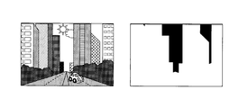
- FIG. 6 is an explanatory diagram for explaining a video generated by the video generation device according to the first embodiment.
- FIG. 6 is an explanatory diagram for explaining a video generated by the video generation device according to the first embodiment.
- FIG. 6 is an explanatory diagram for explaining a video generated by the video generation device according to the first embodiment.
- FIG. 2 is a block diagram showing a configuration example of a television receiver in the first embodiment. It is a conceptual diagram which shows the two-dimensional image
- 1A, 1B, and 1C are explanatory diagrams for explaining a video generated by the video generation device according to the first embodiment.
- the foreground and other backgrounds are distinguished based on the edge strength and the magnitude of movement.
- the foreground is defined as a region having a high feature amount that is easily noticed by a person in the video
- the background is defined as a region other than the foreground in the input video.
- numerical values indicating the strength of the edge and the magnitude of the movement are used as feature quantities that are easily noticed by a person, and whether the foreground or the background is determined by whether the numerical values are equal to or greater than a certain value.
- the depth value of the 2D image is set.
- the basic depth value calculated by a predetermined calculation is set for all the pixels of the two-dimensional image.
- the depth value of the foreground is separately calculated based on a predetermined depth pattern set according to the shape, size, movement, etc. of the subject, and the calculated depth value is reset.
- a left-eye video L and a right-eye video R which are 3D video with parallax, are generated.
- the foreground representing the bird which is a region with a large movement, is divided into other regions, and the depth value is reset for the region with a strong movement to generate a three-dimensional image.
- the method of resetting the depth value is determined by the variance value of the position of the pixel having a strong edge strength, the number of pixels constituting the foreground, and the like.
- FIG. 2 is a block diagram illustrating a configuration example of the television receiver in the first embodiment.
- the control unit 1 is composed of a CPU (Central Processing Unit) or an MPU (Micro Processing Unit), and includes an arithmetic circuit capable of processing video data.
- a control program stored in advance in the ROM 2 is read out to the RAM 3 as appropriate and executed. To do.
- the control unit 1 controls operations of the ROM 2, RAM 3, video storage unit 4, input unit 5, and output unit 6. These are connected to each other via a bus.
- the ROM 2 is composed of a writable and erasable EPROM (Erasable Programmable ROM), a flash memory, or the like, and stores in advance various control programs necessary for the operation of the video generation apparatus.
- EPROM Erasable Programmable ROM
- flash memory or the like
- the RAM 3 is an SRAM or a flash memory, and temporarily stores various data generated when the control unit 1 executes the control program.
- the control unit 1 stores the data of the two-dimensional image in a RAM or The image is stored in the video storage unit 4 composed of a flash memory or the like.
- the two-dimensional video may be a video input from a playback device that plays back a recording medium, a video of a communication wave input from a communication device, or the like.
- MPEG-2 Moving Picture Expert Group 4 phase 2
- MPEG-4 Moving Picture Expert Group 4 phase 4
- H.264 A compressed format such as H.264 may be used, or an uncompressed format may be used.
- Control unit 1 sequentially reads data of 2D video stored in video storage unit 4.
- the two-dimensional video is a video such as terrestrial digital broadcast or BS digital broadcast
- MULTI2 which is a standard encryption of a conditional access system (B-CAS: BS Conditional Access System) is decrypted.
- B-CAS BS Conditional Access System
- the 2D video is a compressed video, the video is decompressed. If the 2D video is an analog video, the video is converted into, for example, an MPEG-2TS digital video.
- the control unit 1 generates a 3D image by performing processing described later. Also, the 3D video is converted into a predetermined method for displaying on the display unit 10 and is output to the display unit 10 for displaying the video via the output unit 6.
- the display unit 10 is a display of a mobile phone, a PDA, a book reader, a game machine, or a music player in addition to a monitor of a television and an information processing terminal, and displays a three-dimensional image including an image generated by processing to be described later. .
- the display unit 10 can also display a 2D video.
- the display unit 10 includes a video switching unit (not shown) that switches the video to display the 2D video or the 3D video.
- FIG. 3 is a conceptual diagram showing a two-dimensional image processed by the control unit 1, and includes time-series images of the (n ⁇ 1) th frame, the nth frame, and the (n + 1) th frame.
- the number of pixels in each frame is, for example, 1920 ⁇ 1080.
- a pixel at the position of x columns and y rows is represented by (x, y) with the upper left point of the frame as the origin.
- the control unit 1 extracts, from each pixel of the two-dimensional image, a strong edge pixel that indicates a pixel in which the difference in shading between adjacent pixels is abrupt.
- the R component is SnR (x, y)
- the G component is SnG (x, y)
- the B component is SnB (x, y).
- the control unit 1 weights SnR (x, y), SnG (x, y), and SnB (x, y) in the same way as the luminance signal of the ISDB-T system in digital broadcasting.
- a gray scale value Gn (x, y) is calculated by taking a weighted average.
- the control unit 1 performs processing using a Laplacian filter for Gn (x, y).
- 4A and 4B are explanatory diagrams showing a Laplacian filter.
- the Laplacian filter is a process for sharpening the edge of an image by adding a value G ′′ n (x, y) obtained by second-order differentiation of Gn (x, y) to a gray scale value Gn (x, y).
- control unit 1 calculates a difference between adjacent pixels in the row direction and the column direction, and calculates a square root of the sum of the squares of the respective differences. This edge strength En (x, y) is calculated for all pixels.
- the control unit 1 divides the entire frame into blocks of 5 ⁇ 5 pixels and calculates Eave (j, k).
- the reason for dividing the block into 5 ⁇ 5 pixel blocks is to simplify the process and reduce noise.
- FIG. 5A and FIG. 5B are schematic views showing edge intensity average Eave (j, k) and strong edge pixel information Hn (x, y).
- FIG. 5A is a schematic diagram illustrating a two-dimensional image divided into blocks.
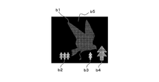
- the block a1 is a block constituting an image representing a bird and has a large difference in pixel value from adjacent pixels. Therefore, the block a1 has a large edge intensity average Eave (j, k).
- the block a2 is a block constituting the sky, and the difference in pixel value between adjacent pixels is small. Therefore, the value of the edge intensity average Eave (j, k) is small in the block a2.
- the control unit 1 sets the strong edge pixel information Hn (x, y) to 1 for pixels whose edge intensity average Eave (j, k) is equal to or greater than a preset threshold Th0. And the pixel having a threshold value less than Th0 has the strong edge pixel information Hn (x, y) set to 0.
- the strong edge pixel information Hn (x, y) is used in the foreground and background classification described later. Therefore, the threshold value Th0 is set to a value suitable for classifying a two-dimensional image into foreground and background from the viewpoint of edge strength.
- a strong edge pixel that is a pixel having a strong edge can be extracted from the value of the strong edge pixel information Hn (x, y).
- a pixel whose strong edge pixel information Hn (x, y) is 1 is shown in white, and a pixel whose 0 is 0 is shown in black.
- the procedure for calculating the strong edge pixel information Hn (x, y) is not limited to the procedure described above.
- the strong edge pixel information Hn (x, y) may be calculated based on whether or not the number of pixels having an edge intensity equal to or greater than the threshold Th0 among all the pixels in the block is greater than or equal to a predetermined number.
- control unit 1 extracts a moving object constituent pixel that is a pixel indicating a two-dimensional image with a large movement.
- a two-dimensional image with a large movement is considered to have a large change in pixel value. Therefore, a pixel having a large change in pixel value compared to the pixel values of the previous and subsequent frames is considered as a pixel having a large movement.
- the control unit 1 determines whether or not the absolute difference information Dn (x, y) is equal to or greater than a preset threshold value Th1, and indicates whether or not the high difference information Bn ( x, y) is calculated.
- the pixel having the threshold value Th1 or more sets the high difference information Bn (x, y) to 1, and the pixel having the threshold value Th1 less than 0 sets the high difference information Bn (x, y) to 0.
- the high difference information Bn (x, y) is used in the foreground and background classification described later. Therefore, the threshold value Th1 is set to a value suitable for distinguishing between the foreground and the background from the viewpoint of the magnitude of motion in the two-dimensional video.
- FIG. 6A, 6B, and 6C are schematic diagrams showing a binary video based on the high difference information Bn (x, y) and Bn + 1 (x, y), and FIG. 6A shows the high difference information Bn (x, y). Pixels that are 1 are shown in white and pixels that are 0 are shown in black.
- FIG. 6B shows pixels whose high difference information Bn + 1 (x, y) is 1 in white and pixels where 0 is 0 in black.
- the moving object constituent pixel information Mn (x, y), which is the logical product of the high difference regions Bn (x, y) and Bn + 1 (x, y), is calculated.
- the control unit 1 has a large change in pixel value for a pixel having the moving object constituent pixel information Mn (x, y) of 1, and a change in the pixel value of a pixel having the moving object constituent pixel information Mn (x, y) of 0. Is small. Therefore, the moving object constituent pixels can be extracted from the value of the moving object constituent pixel information Mn (x, y).
- FIG. 6C shows a region where the moving object constituent pixel information Mn (x, y) is 1 in white and a region where 0 is black in black.
- a pixel having a large motion or a pixel having a strong edge in a 2D image is a pixel indicating a subject that is viewed by a person viewing the 2D image, and is considered to constitute a foreground. On the other hand, other pixels are considered to constitute the background.
- the control unit 1 After obtaining the moving object constituent pixel information Mn (x, y), the control unit 1 performs a labeling process to distinguish the foreground and the background and extract the foreground.
- the control unit 1 attaches the same label to a group of pixels in which the strong edge region information Hn (x, y) is 1.
- the same processing is performed for a group of pixels having the moving object constituent pixel information Mn (x, y) of 1 in series. Thereby, the pixels constituting the foreground can be extracted as a region.
- FIG. 7A and FIG. 7B are schematic diagrams showing images obtained by dividing the image of the nth frame for each region.
- the controller 1 divides the region into regions b1 to b4 where the strong edge region information Hn (x, y) is 1 and region b5 where the strong edge region information En (x, y) is 0. .
- the object body pixel information Mn (x, y) is divided into a region b6 where the value is 1 and a region b7 where the strong edge region information Hn (x, y) is 0.
- the foreground information Pn (x, y) is obtained by calculating the logical sum of the strong edge region information Hn (x, y) and the moving object constituent pixel information Mn (x, y). calculate.
- Pixels for which foreground information Pn (x, y) is 1 have pixels in b1 to b4 having strong edge region information Hn (x, y) of 1 or moving body constituent pixel information Mn (x, y) of 1 Is a pixel constituting b6.
- FIG. 7C shows a region where the foreground information Pn (x, y) is 1 in white and a region where 0 is 0 in black.
- not all the desired foreground may be extracted.
- the area that is easy for people to focus on is the entire person's face that is in focus. It is desirable to extract as However, a contour with a clear edge is easily detected as a foreground, but a portion such as a cheek or a forehead with a relatively weak edge is easily determined as a background. Therefore, there are cases where an area determined to be part of the background exists like a hole even though it is a pixel constituting a “human face” that should be determined to be the foreground.
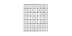
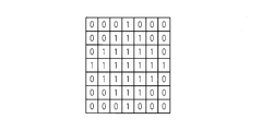
- FIG. 8 is an explanatory diagram showing morphology processing. For the sake of explanation, consider a 7 ⁇ 7 pixel represented by a binary value of 0 or 1.
- This morphological process can appropriately set a portion determined as a background such as a hole as a foreground.
- a portion determined as a background such as a hole as a foreground.
- the location determined as the background which exists like a hole is large, it can be set as a foreground by performing expansion processing and contraction processing a plurality of times.
- control unit 1 determines the composition of the two-dimensional video.
- An area composed of pixels with strong edges or pixels with a large movement may be considered as an area in which a subject that is viewed by the viewer of the video is shown.
- the control unit 1 determines the size, movement, or arrangement of each subject in the two-dimensional image from the number or arrangement of pixels with strong edges or pixels with large movement, and determines whether the composition of the image is of a plurality of types. Determine.
- the composition is an “overhead” type in which the entire landscape is captured as an object from an overhead view, an “up” type in which a specific subject is close-up, and an intermediate between the “overhead” and “up”, and the foreground I think that there are three types of "balance" type with a well-balanced background.
- “Balanced” type refers to a type of video in which main subjects such as people, animals or buildings have the same amount of foreground and other backgrounds, and the number of pixels in the foreground is relatively small.
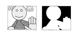
- 9A, 9B, and 9C are explanatory diagrams illustrating the foreground and the background in each composition.
- FIG. 9A is an explanatory diagram showing a “balance” type image, in which foreground information Pn (x, y) is 1 in white, and 0 is in black.
- FIG. 9B is an explanatory diagram showing an “up” type image, in which foreground information Pn (x, y) is 1 in white, and 0 is in black.
- FIG. 9C is an explanatory diagram showing a “bird's-eye view” type image, in which foreground information Pn (x, y) is 1 in white and 0 is in black.
- composition of the image is the up of the subject
- pixels with strong edges are concentrated in the area where the up of the subject is reflected.
- composition of the video is a bird's-eye view
- since many subjects are scattered pixels with strong edges are scattered throughout the frame. Therefore, the positions of pixels with strong edges tend to be more dispersed in the “overhead” type than in the “up” type.
- the procedure by which the control unit 1 determines the composition will be described.
- the control unit 1 counts the foreground pixels. If the number of foreground pixels is less than a preset threshold value Th2 as a result of the counting, it is determined that the composition is a “balance” type.
- Th2 the threshold for discriminating between the “up” type and the “overhead” type and the “balance” type.
- the threshold value Th3 (> Th0) is set to a value suitable for discriminating between pixels constituting a characteristic subject of the video and other pixels.
- the variance value ⁇ 1 for the position of the coordinate of the pixel whose extracted edge strength En (x, y) is equal to or greater than the threshold Th3 is calculated.
- the variance value ⁇ 1 is set to the following ( 13) Calculated by the equation.
- the control unit 1 determines whether or not the variance value ⁇ 1 is greater than or equal to the threshold Th4. When the variance value ⁇ 1 is equal to or greater than the preset threshold Th4, the control unit 1 determines that the composition is an “up” type. When the variance value ⁇ 1 is less than the threshold Th4, it is determined that the composition is the “overhead” type.
- Threshold value Th4 is set to an appropriate value to determine whether the composition of the video is the “up” type or the “overhead” type.
- control unit 1 After determining the composition of the 2D video, the control unit 1 calculates a vanishing point and a vanishing line, and further calculates a basic depth value of the 2D video based on the calculated vanishing point and vanishing line.
- the control unit 1 extracts a pixel having a large edge intensity En (x, y).
- a pixel having a large edge strength En (x, y) is the same pixel as the pixel having a value of the edge strength En (x, y) equal to or greater than the threshold Th3.
- the control unit 1 selects an arbitrary pixel from the pixels having a large edge strength En (x, y), and selects a pixel having a large edge strength En (x, y) in the vicinity of the eight pixels. Subsequently, when there is a pixel having a large edge strength En (x, y) in the vicinity of 8 of the most recently selected pixels, a pixel having a large edge strength En (x, y) is selected. If there are a plurality of pixels having a large edge strength En (x, y) in the vicinity of 8, the procedure of selecting the pixel farthest from the first selected pixel is repeated.
- the control unit 1 calculates a regression line of the group of pixels.
- the regression lines for all of them are calculated.
- the two regression lines are vanishing lines, and the intersection of the calculated regression lines is vanishing Is a point.
- the control unit 1 calculates a basic depth value.
- the basic depth value is a value from 0 to d, and the depth value of the pixel corresponding to the vanishing point is d.
- the vanishing point is not limited to within the frame, but may exist outside the frame. Further, the depth value of the pixel (x, y) located farthest from the vanishing point is the smallest.
- the basic depth value calculates the distance from the vanishing point of each pixel (x, y), and the basic depth value is set to be inversely proportional to the distance from the vanishing point.
- the basic depth value may be calculated based on the composition, the gray scale value Gn (x, y), or the like.
- the basic depth value may be calculated based on the composition, the gray scale value Gn (x, y), or the like.
- Gn gray scale value
- a uniform setting method may be used for the entire video. Therefore, it is desirable to perform different basic depth value setting methods depending on the video.
- the control unit 1 reads a template stored in advance in the ROM 2.
- the depth value of the vanishing point is set to d, and the depth value at each pixel (x, y) of the entire two-dimensional video other than the vanishing point is set.
- the template is associated with a composition, a histogram of gray scale values Gn (x, y) of each pixel of the 2D video, and the like.
- the control unit 1 selects an optimum template from the templates read from the ROM 2 using the composition, the gray scale value Gn (x, y), etc., matches the vanishing point position with the selected template, and other than the vanishing point.
- the depth value of the pixel (x, y) is calculated.
- the control unit 1 When the basic depth value is set, the control unit 1 resets the depth value based on the composition.
- the composition is a “balance” type
- the value of y is the largest among the pixels (x, y) constituting each foreground in each foreground b1 to b4 and b6.
- the foreground depth value is reset according to the basic depth value of one pixel and the pattern of the preset depth value.
- ROM 2 stores data of a plurality of patterns in which depth values are set in various two-dimensional shapes.
- the shape of the pattern includes a shape imitating a bird, a tree, a cloud, a person, or the like, a shape obtained by projecting a spherical shape or a rectangular parallelepiped two-dimensionally, and the like, and a depth value corresponding to the shape is set.
- control unit 1 When resetting, the control unit 1 reads the pattern from the ROM 2. The control unit 1 performs matching with a pattern based on the shape, size, movement, or the like for each of the foregrounds b1 to b4 and b6, and selects an appropriate pattern.
- the depth value set in the pattern only indicates the relative depth value in the pattern. Therefore, when resetting the depth value in the 2D video, the depth value of the 2D video that is the reference of each foreground is required. Therefore, the basic depth value of one pixel having the largest y value among the pixels (x, y) constituting the foreground for each foreground b1 to b4 and b6 is used as a reference value, and each foreground b1 to b4 and b6 is configured. The depth value of the pixel (x, y) is reset using the depth value of the pattern.
- the control unit 1 resets the depth value of the pixel (x, y) constituting the foreground to the first depth value DPf.
- the pixel (x, y) constituting the background resets the depth value to the second depth value DPg.
- the average value of the basic depth values of the pixels constituting the foreground is defined as a first depth value DPf
- the average value of the basic depth values of the pixels constituting the background is defined as a second depth value DPg.
- the first depth value DPf and the second depth value DPg may be values calculated by weighted average of the basic depth values weighted based on the number of pixels of each foreground or the variance value ⁇ 1.
- the foreground is considered to be on the front side as a whole, and the first depth value DPf is set to a small value.
- the variance value ⁇ 1 is large, it is considered that the subject is photographed from a distance, and the difference between the first depth value DPf and the second depth value DPg is set to be small.
- the depth value setting method differs from the “balance” type. It is set as follows.
- the composition is a “bird's-eye view” type as a result of the determination, the basic depth value of, for example, one pixel having the largest y value among the foreground b6 made up of moving object constituent pixels is used as a reference value.
- the depth value of the foreground is reset according to the pattern of the depth value and the preset depth value.
- the fast moving area is considered to be the area in the foreground in the 3D image. Therefore, the moving object constituent pixels may calculate and reset the depth value so that the faster movement region has the depth value closer to the front.
- the depth value closest to the foreground among the overlapping foreground depth values may be reset.
- the control unit 1 generates a left-eye video L and a right-eye video R having a parallax based on the set and reset depth values.
- the control unit 1 calculates the shift amount SFTn (x, y) indicating the magnitude of the parallax based on the depth value calculated for each pixel in the nth frame of the 2D video. Assuming that the shift amount is SFTn (x, y) and the depth value is DPn (x, y), the control unit 1 calculates the shift amount according to equation (14) that represents the relationship between the depth value and the shift amount.
- the shift amount SFTn (x, y) is set to a value from ⁇ s to s.
- equation (14) is used for associating the depth value with the shift amount, but there is no problem even if the equation to be used is a nonlinear equation. Needless to say.
- a lookup table in which the shift amount corresponding to each depth value from 0 to d is created in advance may be used.
- a left-eye video L and a right-eye video R are generated according to the calculated shift amount SFTn (x, y).
- the left-eye video L shifts the pixel in the right direction when the value of SFTn (x, y) is positive, and shifts the pixel in the left direction when the value is negative.
- the right-eye video R when the value of SFTn (x, y) is positive, the pixel is shifted leftward, and when it is negative, the pixel is shifted rightward.
- Some pixels may not be able to obtain an effective pixel value for a part of the image depending on the image. For this pixel, interpolation is performed from surrounding pixels, and an effective pixel value is set.
- the control unit 1 converts the three-dimensional image into a predetermined method for displaying on the display unit 10 and outputs it to the display unit 10 via the output unit 6.
- FIG. 10A, FIG. 10B, FIG. 10C, and FIG. 10D are schematic diagrams illustrating examples of a predetermined method for displaying a three-dimensional image on the display unit 10.
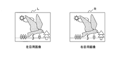
- FIG. 10A is a schematic diagram showing a left-eye image L and a right-eye image R.
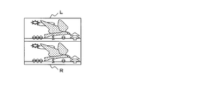
- the predetermined method includes a top-and-bottom method in which the left-eye video L and the right-eye video R are halved in the row direction as shown in FIG. 10B, and the column-direction resolution as shown in FIG. 10C.
- FIG. 11 is a flowchart illustrating a processing procedure of the control unit 1 according to the first embodiment.
- step S10 2D video is input to the control unit 1 from a broadcast wave receiving antenna (not shown) (step S10). Then, the control unit 1 stores the 2D video data in the video storage unit 4 (step S12). The control unit 1 sequentially reads the stored two-dimensional video data (step S14).
- the control unit 1 extracts strong edge pixels for each pixel of the two-dimensional image (step S16). Subsequently, the moving object constituent pixels are extracted (step S18).
- the control unit 1 performs a labeling process on the foreground of the 2D video, and classifies the foreground and the background (step S20).
- the control unit 1 determines the composition of the 2D video (step S22). Further, the basic depth value of each pixel (x, y) is calculated and set (step S24). The control unit 1 resets the depth value based on the composition (step S26).
- the control unit 1 generates a 3D image of the left eye image L and the right eye image R based on the depth value (step S28).
- the control unit 1 converts the generated left-eye video L and right-eye video R into a predetermined method (step S30).
- the converted video is output to the display unit 10 via the output unit 6 (step S32).
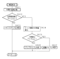
- FIG. 12 is a flowchart illustrating a processing procedure in which the control unit 1 calculates the strong edge pixel information Hn (x, y).
- the control unit 1 assigns constant weights to the R component SnR (x, y), G component SnG (x, y), and B component SnB (x, y) of the pixel (x, y) as shown by the equation (1).
- a weighted average is taken to calculate a gray scale value Gn (x, y) (step S161).
- control unit 1 performs processing using a Laplacian filter expressed by equation (2) (step S162) and emphasizes the edge of the two-dimensional video.
- the control unit 1 calculates the edge intensity En (x, y) expressed by the equation (3) for all the pixels (step S163).
- the control unit 1 divides the entire frame into a predetermined number of blocks (step S164).
- the control unit 1 calculates Eave (j, k) that is an average value of the edge intensities En (x, y) of the block to which the pixel (x, y) belongs after division (step S165).
- the control unit 1 determines whether the edge intensity average Eave (j, k) is equal to or greater than a preset threshold Th0, calculates strong edge pixel information Hn (x, y), and determines strong edge pixel information Hn (x , Y) is a strong edge pixel of 1 (step S166).
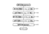
- FIG. 13 is a flowchart illustrating a processing procedure in which the control unit 1 calculates the moving object constituent pixel information Mn (x, y).
- the control unit 1 calculates the absolute difference information Dn (x, y) by taking the absolute value of the difference between the gray scale values Gn (x, y) and Gn ⁇ 1 (x, y) as shown in the equation (8). (Step S181).
- control unit 1 determines whether or not the absolute difference information Dn (x, y) is equal to or greater than a preset threshold value Th1, and indicates whether or not the high difference information Bn ( x, y) is calculated (step S182).
- the control unit 1 performs the same calculation to calculate the absolute difference information Dn + 1 (x, y) (step S183). Further, the control unit 1 calculates the high difference information Bn + 1 (x, y) from the absolute difference information Dn + 1 (x, y) (step S184). The control unit 1 calculates moving object constituent pixel information Mn (x, y) that is a logical product of the high difference regions Bn (x, y) and Bn + 1 (x, y), and moves the moving object constituent pixel information Mn (x, y). The moving object constituent pixels whose y) is 1 are extracted (step S185).
- FIG. 14 is a flowchart illustrating a processing procedure in which the control unit 1 determines the composition of the two-dimensional video.
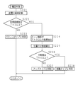
- the control unit 1 counts the pixels constituting the foreground (step S221). Based on the counting result, the control unit 1 determines whether or not the number of pixels is equal to or greater than a preset threshold value Th2 (step S222). If the number of foreground pixels is less than the threshold Th2 (NO in step S222), it is determined that the composition of the nth frame is the “balance” type (step S223).
- Step S222 When the number of pixels constituting the foreground is equal to or greater than the threshold Th2 (YES in Step S222), pixels whose edge intensity En (x, y) is equal to or greater than a preset threshold Th3 are extracted (Step S224). The variance value ⁇ 1 for the pixel position indicated by the equation (13) is calculated (step S225).
- the control unit 1 determines whether or not the variance value ⁇ 1 is greater than or equal to the threshold value Th4 (step S226). If the variance value ⁇ 1 is less than the threshold value Th4 (NO in step S226), the composition is “up” type. It is determined that it exists (step S227). If the variance value ⁇ 1 is greater than or equal to the threshold Th4 (YES in step S226), it is determined that the composition is the “overhead” type (step S228).
- FIG. 15 is a flowchart illustrating a processing procedure in which the control unit 1 resets the depth value.
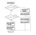
- the control unit 1 determines whether or not the composition determined by the above-described procedure is a “balance” type (step S261). If it is the balance type (YES in step S261), one pixel having the largest y value is selected for each foreground b1 to b4 and b6 (step S262). Using the selected basic depth value of one pixel as a reference, the depth values of the pixels (x, y) constituting each of the foregrounds b1 to b4 and b6 are reset (step S263).
- step S264 it is determined whether or not the composition is “up” type.
- the control unit 1 resets the depth value of the pixels constituting the foreground to the first depth value DPf (Step S265).
- the pixels constituting the background reset the depth value to the second depth value DPg (step S266).
- the control unit 1 selects one pixel having the largest y value of the moving object constituent pixels constituting b6. (Step S267).
- the depth value of the moving object constituent pixel is reset according to the basic depth value and the preset depth value pattern for the selected pixel (step S268).
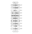
- FIG. 16 is a flowchart illustrating a processing procedure in which the control unit 1 generates a 3D video.
- the control unit 1 calculates the shift amount SFTn (x, y) of the two-dimensional image corresponding to the depth value DPn (x, y) as shown in the equation (14) (step S281).
- the control unit 1 shifts the two-dimensional video according to the calculated shift amount SFTn (x, y) (step S282).
- a pixel in which an effective pixel value cannot be obtained for a part of the image due to pixel shift is interpolated from surrounding pixels (step S283), and an effective pixel value is set.
- the video generation apparatus calculates the depth value in consideration of factors such as the composition of the screen, the magnitude of the motion, and whether the foreground or the background, so that a natural three-dimensional video can be generated.
- Second Embodiment A second embodiment will be described.
- the composition is an “up” type
- the first depth value and the second depth value are always set to constant values.
- a predetermined value is always used for the depth value in the pixels that make up the foreground and the depth value in the pixels that make up the background, creating a video with a sense of depth and stereoscopic effect. You may be able to.
- the process of the control part 1 can be simplified by always using a fixed value for the depth value.
- control unit 1 in the present embodiment does not set the basic depth value when the composition is the “up” type, and sets the depth values of the foreground and the background to constant values.
- the control unit 1 in the present embodiment will be described.
- the control unit 1 receives a two-dimensional image from a broadcast wave receiving antenna.
- the control unit 1 causes the video storage unit 4 to store 2D video data.
- the controller 1 sequentially reads the recorded 2D video data.
- the control unit 1 extracts strong edge pixels and moving object constituent pixels. In addition, a labeling process is performed on the foreground of the 2D video to distinguish the foreground and the background.
- the control unit 1 sets the depth value based on the foreground information Pn (x, y) and the edge strength En (x, y).
- the control unit 1 counts the foreground pixels and determines whether or not the number of pixels is equal to or greater than a preset threshold Th2. When the number of pixels in the foreground is less than the threshold Th2, the composition is a “balance” type, so the control unit 1 generates a basic depth value and resets the foreground depth value.
- the control unit 1 extracts pixels whose edge intensity En (x, y) is equal to or greater than the threshold Th3, and sets a variance value ⁇ 1 for the positions of these pixels. calculate.
- the control unit 1 determines whether or not the variance value ⁇ 1 is equal to or greater than the threshold value Th4.
- the composition is an “up” type. Accordingly, the first depth value DPf, which is a constant value, is set for the pixels constituting the foreground, and the second depth value DPg, which is a constant value, is set for the pixels constituting the background.
- the control unit 1 calculates and sets the basic depth value, and resets the depth value of the moving object constituent pixels.
- the control unit 1 Based on the depth value DPn (x, y), the control unit 1 generates a three-dimensional image of the left-eye video L and the right-eye video R, and uses the generated left-eye video L and right-eye video R in a proper manner.
- the data is converted and transmitted to the display unit via the output unit 6.
- the display unit 10 displays a 3D image.
- FIG. 17 is a flowchart illustrating a processing procedure of the control unit 1 according to the second embodiment.
- the control unit 1 stores the data of the 2D video in the video storage unit 4 (step S42).
- the control unit 1 sequentially reads the stored 2D video data (step S44).
- the control unit 1 extracts a strong edge pixel for each pixel of each frame of the 2D video (step S46). Further, the control unit 1 extracts moving object constituent pixels (step S48).
- Control unit 1 performs a labeling process on the foreground of the 2D video. Further, the control unit 1 calculates the foreground information Pn (x, y) by taking the logical sum of the strong edge region information Hn (x, y) and the moving object constituent pixel information Mn (x, y), and foreground information Pn (x, y) is obtained. And the background (step S50).
- the control unit 1 determines the composition and calculates and sets the depth value based on the determined composition (step S52).
- the control unit 1 generates a three-dimensional image of the left eye image L and the right eye image R based on the depth value (step S54).
- the control unit 1 converts the generated left-eye video L and right-eye video R into a predetermined method (step S56).
- the control unit 1 outputs the converted video to the display unit 10 via the output unit 6 (step S58).
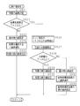
- FIG. 18 is a flowchart illustrating a processing procedure in which the control unit 1 according to the second embodiment sets a depth value.
- Control unit 1 counts the pixels constituting the foreground (step S521). Based on the counting result, the control unit 1 determines whether or not the number of pixels is equal to or greater than a preset threshold value Th2 (step S522).
- control unit 1 sets the basic depth value because the composition is a “balance” type (step S523). In addition, the control unit 1 selects one pixel that is the pixel having the largest y value among the pixels (x, y) constituting the foreground (step S524). Further, the depth value of the foreground is reset (step S525).
- control unit 1 extracts pixels whose edge intensity En (x, y) is greater than or equal to the threshold Th3 (step S526).
- a variance value ⁇ 1 for the extracted pixel position is calculated (step S527).
- the control unit 1 determines whether or not the variance value ⁇ 1 is greater than or equal to the threshold Th4 (step S528). If the variance value ⁇ 1 is greater than or equal to the threshold Th4 (YES in step S528), since the composition is the “up” type, the depth value DPf is set in the foreground information (step S529). Further, the depth value DPg is set in the background information (step S530).
- the control unit 1 sets the basic depth value because the composition is the “overhead” type (step S531). Moreover, the control part 1 selects 1 pixel which is a pixel with the largest y value among moving body structure pixels (step S532). Further, the depth value of the moving object constituent pixels is reset (step S533).
- This embodiment can generate an image with a sense of depth and a stereoscopic effect by using constant values for the depth value of the foreground and the depth value of the background in the “up” type image,
- the process of the control unit 1 can be simplified.
- the processing procedure for determining the composition performed by the control unit 1 is different from the processing procedure (step S22) in the first embodiment.
- the variance value of the edge intensity of all pixels is used in determining the composition of the video, the composition of the video can be accurately determined.
- the control unit 1 in the present embodiment first counts the number of pixels constituting the foreground. It is determined whether or not the counted number of pixels is equal to or greater than a preset threshold value Th2. When the number of pixels in the foreground is less than the threshold value Th2, the composition is determined to be a “balance” type.
- control unit 1 calculates the variance value ⁇ 2 of the values of the edge intensity En (x, y) of all the pixels according to the equation (15).
- pixels with strong edges are concentrated in the area where the subject is shown.
- the video is a bird's-eye video, a large number of subjects are scattered, so pixels with strong edges are scattered throughout the frame.
- the variance value ⁇ 2 of the edge intensity En (x, y) is generally larger in the up-view image of the subject than in the overhead view image.
- the control unit 1 determines whether or not the variance value ⁇ 2 is equal to or greater than the threshold value Th5. If the variance value ⁇ 2 is equal to or greater than the threshold value Th5, the control unit 1 determines that the composition is an “up” type. If the variance value ⁇ 2 is less than the threshold Th5, it is determined that the composition is the “overhead” type.
- FIG. 19 is a flowchart illustrating a processing procedure in which the control unit 1 according to the third embodiment determines the composition.
- the control unit 1 counts the foreground pixels (step S621). Based on the counting result, the control unit 1 determines whether or not the number of pixels is greater than or equal to a preset threshold Th2 (step S622). On the other hand, when the number of pixels in the foreground is less than the threshold Th2 (NO in step S622), the control unit 1 determines that the composition of the nth frame is a “balance” type (step S623).
- control unit 1 calculates the variance value ⁇ 2 of the edge intensity En (x, y) of all pixels (step S624).
- the control unit 1 determines whether or not the variance value ⁇ 2 is equal to or greater than the threshold value Th5 (step S625). If the variance value ⁇ 2 is less than the threshold value Th5 (NO in step S625), the composition is an “up” type. It is determined that it exists (step S626). On the other hand, when the variance value ⁇ 2 is greater than or equal to the threshold Th5 (YES in step S625), the control unit 1 determines that the composition is the “overhead” type (step S627).
- the composition of the video can be accurately determined.
- FIG. 20 is a block diagram showing hardware parts of a television receiver according to a fourth embodiment.
- a program for operating the control unit 1 is stored in the ROM 2 by causing the reading unit 9 such as a disk drive to read the portable recording medium 20A such as a CD-ROM, DVD disk, or USB memory.
- the program may include a semiconductor memory 20B such as a flash memory storing the program in the control unit 1, and is connected to the communication unit 8 through a communication network N such as the Internet. You may download from the server computer.
- a semiconductor memory 20B such as a flash memory storing the program in the control unit 1
- a communication network N such as the Internet. You may download from the server computer.
- the control unit 1 shown in FIG. 20 reads a program for executing the above-described various software processes from a portable recording medium or a semiconductor memory, or downloads it from another server computer (not shown) via the communication network N.
- the program is installed as a control program, loaded into the ROM 2 and executed. Thereby, it functions as the control unit 1 described above.
- composition in the present invention is not limited to the three types described above, and other compositions may be provided based on the size, movement, or arrangement of the subject.
- control unit 1 does not have to determine the composition.
- the control unit 1 extracts the pixels constituting the foreground from the strong edge region information Hn (x, y) and the moving object constituent pixel information Mn (x, y), and calculates the depth value of the extracted pixels by the method described above. It may be reset to generate a 3D video.
- the strong edge region information Hn (x, y) and the moving object constituent pixel information Mn (x, y) include pixel values SnR (x, y) and SnG (x instead of the gray scale value Gn (x, y). , Y), one or more of SnB (x, y), and may be calculated by determining whether or not the pixel value is equal to or greater than a predetermined threshold value.
- the absolute difference information Dn (x, y) may be calculated based on the gray scale value of the pixel (x, y) in three or more frames, or the pixel values of the R, G, and B components in three or more frames. You may calculate using one or more.
- the RGB color space information shown in SnR (x, y), SnG (x, y), SnB (x, y) is converted into another color space represented by HSV, YUV, etc. It goes without saying that is possible.
- Control unit 2 ROM 3 RAM 4 video storage unit 5 input unit 6 output unit 7 tuner 8 communication unit 9 reading unit 10 display unit 20A portable recording medium 20B semiconductor memory
Landscapes
- Engineering & Computer Science (AREA)
- Multimedia (AREA)
- Signal Processing (AREA)
- Computer Vision & Pattern Recognition (AREA)
- Physics & Mathematics (AREA)
- General Physics & Mathematics (AREA)
- Theoretical Computer Science (AREA)
- Testing, Inspecting, Measuring Of Stereoscopic Televisions And Televisions (AREA)
- Processing Or Creating Images (AREA)
Abstract
2次元映像に基づいて自然な3次元映像を生成する映像生成装置、映像表示装置、テレビ受像装置、映像生成方法及びコンピュータプログラムを提供する。複数の画素によって構成される2次元映像の各画素に対応する奥行を示す奥行値を算出して3次元映像を生成する映像生成装置において、前記2次元映像を構成する各画素の画素値と該各画素に隣接する画素の画素値との差分を算出する第1差分算出部、該第1差分算出部で算出した差分が所定の第1閾値以上である画素を抽出する第1抽出部、前記2次元映像を構成する各画素の一のフレームにおける画素値と他のフレームにおける画素値との差分を算出する第2差分算出部、該第2差分算出部で算出した差分が所定の第2閾値以上である画素を抽出する第2抽出部及び前記第1抽出部及び第2抽出部の抽出結果に基づいて前記2次元映像の各画素に対応する奥行値を算出する奥行算出部を備えることを特徴とする映像生成装置を提供する。
Description
本発明は、2次元映像から3次元映像を生成する映像生成装置、映像表示装置、テレビ受像装置、映像生成方法及びコンピュータプログラムに関する。
3次元映像を表示する表示装置が普及しつつあるが、3次元映像の量はまだ少なく、また、2次元で収録した映像を3次元映像として視聴したいという要望もある。
そこで2次元映像から疑似的な3次元映像を生成することが考えられる。この場合は2次元映像に適切な奥行の情報を与えなければならない。例えば特許文献1には、2次元映像全体の構図から、画面全体について設定されている所定の3種類の基本奥行モデルを合成する比率を算出し、合成された基本奥行モデルに基づいて3次元映像の奥行値を2次元映像に与え、3次元映像を生成する映像生成装置が記載されている。
しかし、特許文献1における映像生成装置では画面全体に予め設定された基本奥行モデルを2次元映像に当てはめるのみである。従って奥行値が不適切なことがあり、不自然な3次元映像を生成することがあった。
本発明は係る事情によりなされたものであり、自然な3次元映像の生成を目的とする映像生成装置、映像表示装置、テレビ受像装置、映像生成方法及びコンピュータプログラムを提供する。
本発明における映像生成装置は、複数の画素によって構成される2次元映像の各画素に対応する奥行を示す奥行値を算出して3次元映像を生成する映像生成装置において、前記2次元映像を構成する各画素の画素値と該各画素に隣接する画素の画素値との差分を算出する第1差分算出部、該第1差分算出部で算出した差分が所定の第1閾値以上である画素を抽出する第1抽出部、前記2次元映像を構成する各画素の一のフレームにおける画素値と他のフレームにおける画素値との差分を算出する第2差分算出部、該第2差分算出部で算出した差分が所定の第2閾値以上である画素を抽出する第2抽出部及び前記第1抽出部及び第2抽出部の抽出結果に基づいて前記2次元映像の各画素に対応する奥行値を算出する奥行算出部を備えることを特徴とする。
本発明によれば、2次元映像の一部の画素を抽出し、抽出結果に基づいて奥行値を算出するので、自然な3次元映像を生成することができる。
本発明における映像生成装置は、前記第1差分算出部で算出した差分が前記第1閾値より大きい所定の第3閾値以上である画素を抽出する第3抽出部及び該第3抽出部で抽出した各画素が存在する位置の分散の程度を示す位置の分散値を算出する分散値算出部をさらに備え、前記奥行算出部は、前記分散値算出部で算出した位置の分散値と、前記第1抽出部又は第2抽出部で抽出された画素の総数とに基づいて前記奥行値を算出するよう構成してあることを特徴とする。
本発明によれば、画素の位置の分散値に基づいて奥行値を算出するので、さらに2次元映像に応じた自然な3次元映像を生成することができる。
本発明における映像生成装置は、前記第1差分算出部で算出した差分の分散値を算出する第2分散値算出部をさらに備え、前記奥行算出部は、前記第2分散値算出部で算出した各画素の差分の分散値と、前記第1抽出部又は第2抽出部で抽出された画素の総数とに基づいて前記奥行値を算出するよう構成してあることを特徴とする。
本発明によれば、各画素の差分の分散値に基づいて奥行値を算出するので、さらに2次元映像に応じた自然な3次元映像を生成することができる。
本発明における映像表示装置は、映像生成装置及び該映像生成装置により生成された前記3次元映像を表示する表示部を備えることを特徴とする。
本発明によれば、前述した効果を映像表示装置にて実現することができる。
本発明におけるテレビ受像装置は、2次元映像を含むテレビ放送波を受信するチューナ部、該チューナ部により受信した2次元映像に基づき3次元映像を生成する請求項1から3のいずれか1つに記載の映像生成装置及び該映像生成装置により生成された前記3次元映像を表示する表示部を備えることを特徴とする。
本発明によれば、前述した効果をテレビ受像装置にて実現することができる。
本発明における映像生成方法は、複数の画素によって構成される2次元映像の各画素に対応する奥行を示す奥行値を算出して3次元映像を生成する映像生成方法において、前記2次元映像を構成する各画素の画素値と該各画素に隣接する画素の画素値との差分を算出する第1差分算出ステップ、該第1差分算出ステップで算出した差分が所定の第1閾値以上である画素を抽出する第1抽出ステップ、前記2次元映像を構成する各画素の一のフレームにおける画素値と他のフレームにおける画素値との差分を算出する第2差分算出ステップ、該第2差分算出ステップで算出した差分が所定の第2閾値以上である画素を抽出する第2抽出ステップ及び前記第1抽出ステップ及び第2抽出ステップの抽出結果に基づいて前記2次元映像の各画素に対応する奥行値を算出する奥行算出ステップを備えることを特徴とする。
本発明によれば、2次元映像の一部の画素を抽出し、抽出結果に基づいて奥行値を算出するので、自然な3次元映像を生成することができる。
本発明におけるコンピュータプログラムは、複数の画素によって構成される該2次元映像の各画素に対応する奥行を示す奥行値を算出して3次元映像を生成させるコンピュータプログラムにおいて、前記2次元映像を構成する各画素の画素値と該各画素に隣接する画素の画素値との差分を算出する第1差分算出ステップ、該第1差分算出ステップで算出した差分が所定の第1閾値以上である画素を抽出する第1抽出ステップ、前記2次元映像を構成する各画素の一のフレームにおける画素値と他のフレームにおける画素値との差分を算出する第2差分算出ステップ、該第2差分算出ステップで算出した差分が所定の第2閾値以上である画素を抽出する第2抽出ステップ及び前記第1抽出ステップ及び第2抽出ステップの抽出結果に基づいて前記2次元映像の各画素に対応する奥行値を算出する奥行算出ステップを含む処理をコンピュータに実行させることを特徴とする。
本発明によれば、2次元映像の一部の画素を抽出し、抽出結果に基づいて奥行値を算出するので、自然な3次元映像を生成することができる。
本発明によれば、算出した2次元映像の各画素のエッジ強度が所定の閾値以上である画素を抽出し、また算出した2次元映像の1のフレームにおける画素値と他のフレームにおける画素値との差分が所定の閾値以上である画素を抽出し、それらの抽出結果に基づいて奥行値を算出するので、自然な3次元映像を提供することができる。
第1の実施の形態
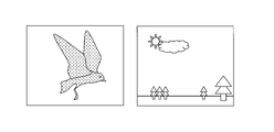
以下、第1の実施の形態を図を用いて説明する。図1A、図1B、図1Cは第1の実施の形態における映像生成装置により生成される映像を説明するための説明図である。
以下、第1の実施の形態を図を用いて説明する。図1A、図1B、図1Cは第1の実施の形態における映像生成装置により生成される映像を説明するための説明図である。
本実施の形態における映像生成装置は、図1Aに示す鳥、木、太陽、空、雲、地面等の被写体により構成された2次元映像から3次元映像を生成するにあたり、一旦、2次元映像のエッジ強度及び動きの大きさに基づいて前景とその他の背景とを区分する。ここで前景とは、映像中で人が注目しやすい特徴量が高い領域と定義し、背景とは入力映像中の前景以外の領域と定義する。
本実施の形態では、人が注目しやすい特徴量として、エッジの強度及び動きの大小を示す数値を用い、その数値が一定値以上か否かで前景か背景かを判定する。判定を行うことにより、図1Bに示すようにエッジが強い又は動きが大きい領域である鳥、及びエッジが強い領域である木が前景となり、背景と区分される。
次に2次元映像の奥行値を設定する。まず2次元映像の全ての画素について、所定の計算により算出した基本奥行値を設定する。続いて、被写体の形状、大きさ又は動き等に合わせて設定された所定の奥行パタンに基づいて前景の奥行値を別途算出し、算出した奥行値を再設定する。設定及び再設定した奥行値に基づいて、視差の付いた3次元映像である左目用映像L及び右目用映像Rを生成する。
また、図1Cに示すように動きの大きい領域である鳥を表す前景とその他の領域とを区分し、動きの強い領域について奥行値を再設定して3次元映像を生成する。
奥行値の再設定の方法は、エッジ強度の強い画素の位置の分散値及び前景を構成する画素数等によって判別する。
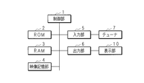
本実施の形態における映像生成装置、映像表示装置及びテレビ受像装置の構成について説明する。本実施の形態におけるテレビ受像装置及び映像表示装置は映像生成装置を含む。図2は、第1の実施の形態におけるテレビ受像装置の一構成例を示すブロック図である。
制御部1は、CPU(Central Processing Unit)又はMPU(Micro Processing Unit)等で構成され、映像のデータを処理できる演算回路を備え、ROM2に予め格納されている制御プログラムを適宜RAM3に読み出して実行する。その他、制御部1は、ROM2、RAM3、映像記憶部4、入力部5及び出力部6の動作を制御する。なおこれらは、それぞれバスを介して相互に接続されている。
ROM2は、書き込み及び消去可能なEPROM(Erasable Programmable ROM)又はフラッシュメモリ等で構成され、映像生成装置が動作するために必要な種々の制御プログラムを予め格納してある。
RAM3はSRAM又はフラッシュメモリ等であり、制御部1による制御プログラムの実行時に発生する種々のデータを一時的に記憶する。
制御部1は、放送波の2次元映像が図示しない放送波受信アンテナから、放送波受信用のチューナ7に接続された入力部5を介して入力された場合、2次元映像のデータをRAM又はフラッシュメモリ等で構成される映像記憶部4に記憶する。2次元映像は、記録メディアを再生する再生装置から入力される映像でもよく、通信装置から入力される通信波の映像等でもよい。また、MPEG-2(Moving Picture Expert Group phase2)、MPEG-4(Moving Picture Expert Group phase4) 又はH.264等の圧縮された形式でもよく、非圧縮の形式でもよい。
制御部1は、映像記憶部4に記憶された2次元映像のデータを順次読み出す。2次元映像が地上デジタル放送又はBSデジタル放送等の映像である場合は限定受信方式(B-CAS : BS Conditional Access System)の標準暗号であるMULTI2を復号する。2次元映像が圧縮された映像である場合は伸長し、アナログ映像である場合には、例えばMPEG-2TSのデジタル映像に変換する。
制御部1は、後述する処理を行って3次元映像を生成する。また、3次元映像を表示部10で表示するための所定の方式に変換し、出力部6を介して、映像を表示する表示部10へ出力する。
表示部10は、テレビ、情報処理端末のモニタの他、携帯電話機、PDA、ブックリーダ、ゲーム機又は音楽プレーヤのディスプレイ等であり、後述する処理により生成された映像を含む3次元映像を表示する。表示部10は、3次元映像の他に2次元映像も表示することができ、この場合は2次元映像又は3次元映像を表示するよう映像を切り替える図示しない映像切替部を備える。
制御部1について説明する。図3は制御部1が処理を行う2次元映像を示す概念図であり、時系列の第(n-1)フレーム、第nフレーム及び第(n+1)フレームの映像を含む。
各フレームの画素数は例えば1920×1080である。フレームの左上の点を原点とし、x列y行の位置における画素を(x,y)で表す。制御部1は2次元映像の各画素から、隣接する画素の濃淡の差が急激である画素を示す強エッジ画素を抽出する。
第nフレームにおける画素(x,y)の画素値のRGB成分のうち、R成分をSnR(x,y)、G成分をSnG(x,y)、B成分をSnB(x,y)とする。制御部1は式(1)に示すように、SnR(x,y)、SnG(x,y)、SnB(x,y)にデジタル放送におけるISDB-T方式の輝度信号と同様の重み付けをした加重平均を取ることにより、グレースケール値Gn(x,y)を算出する。

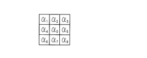
制御部1は、Gn(x,y)についてラプラシアンフィルタによる処理を行う。図4A及び図4Bはラプラシアンフィルタを表す説明図である。ラプラシアンフィルタはグレースケール値Gn(x,y)にGn(x,y)を2次微分した値G”n(x,y)を加えることにより映像のエッジを先鋭にする処理である。
図4Aに示すように例えば注目画素とその8近傍の画素からなる3×3の画素を考え、注目画素のグレースケール値Gn(x,y)をα0、8近傍の画素値をα1からα8とする。この画素に対し図4Bに示すように8方向のラプラシアンフィルタで処理を行う場合、2次微分値G”n(x,y)は式(2)で示される。

制御部1は、ラプラシアンフィルタで処理を行うと、行方向及び列方向に隣接する画素の差分を各々算出し、各々の差分の2乗の和の平方根を算出する。このエッジ強度En(x,y)を全ての画素について算出する。

画素(x,y)が列方向にj番目で行方向にk番目の5×5のブロックに属する場合、ブロックを構成する25画素のエッジ強度En(x,y)の平均値をEave(j,k)で表す。なお、xは5j-4から5j列までの画素に属し、yは5k-4から5k行までの画素に属するので、xとj、yとkには(4)及び(5)式が成り立つ。但し、jは0から384までの整数、kは0から216までの整数である。

制御部1は、フレーム全体を5×5画素のブロックに分割し、Eave(j,k)を算出する。このように5×5画素のブロックに分割する理由は処理を簡易にし、また、ノイズを低減させるためである。
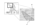
図5A及び図5Bはエッジ強度平均Eave(j,k)及び強エッジ画素情報Hn(x,y)を示す模式図である。図5Aはブロック単位に分割した2次元映像を示した模式図である。ブロックa1は鳥を表す映像を構成するブロックであり隣接する画素との画素値の差分が大きい。従ってブロックa1はエッジ強度平均Eave(j,k)の値が大きい。一方、ブロックa2は空を構成するブロックであり、隣接する画素との画素値の差分が小さい。従ってブロックa2はエッジ強度平均Eave(j,k)の値は小さい。
制御部1は、(6)及び(7)式に示すようにエッジ強度平均Eave(j,k)が予め設定された閾値Th0以上である画素は強エッジ画素情報Hn(x,y)を1とし、閾値Th0未満である画素は強エッジ画素情報Hn(x,y)を0とする。
強エッジ画素情報Hn(x,y)は後述する前景と背景との区分において用いられる。従って閾値Th0はエッジの強さの観点から2次元映像を前景と背景とに区分するのに適した値に設定してある。

これにより、強エッジ画素情報Hn(x,y)の値からエッジの強い画素である強エッジ画素を抽出することができる。図5Bでは強エッジ画素情報Hn(x,y)が1である画素を白色、0である画素を黒色で示してある。
なお、強エッジ画素情報Hn(x,y)を算出する手順は上述した手順に限らない。例えば、ブロック中の全画素のうち、閾値Th0以上のエッジ強度を持つ画素数が予め定められた数以上あるか否かによって強エッジ画素情報Hn(x,y)を算出してもよい。
続いて、制御部1は、動きが大きい2次元映像を示す画素である動物体構成画素を抽出する。動きが大きい2次元映像は、画素値の変化が大きいと考えられる。従って、前後のフレームの画素値と比較して画素値の変化が大きい画素を、動きの大きい画素と考える。
制御部1が動物体構成画素情報Mn(x,y)を算出する手順について説明する。まず、(8)式に示すように、既に算出したグレースケール値Gn(x,y)及び第(n-1)フレームの画素の画素値をグレースケール変換したGn-1(x,y)の差分の絶対値である絶対差分情報Dn(x,y)を算出する。

続いて制御部1は、絶対差分情報Dn(x,y)が予め設定された閾値Th1以上か否かを判定し、差分の絶対値が大きい画素であるか否かを示す高差分情報Bn(x,y)を算出する。(9)及び(10)式に示すように閾値Th1以上である画素は高差分情報Bn(x,y)を1とし、閾値Th1未満である画素は高差分情報Bn(x,y)を0とする。高差分情報Bn(x,y)は後述する前景と背景との区分において用いられる。従って閾値Th1は2次元映像における動きの大きさの観点から前景と背景とに区分するのに適した値に設定してある。

図6A、図6B、図6Cは高差分情報Bn(x,y)及びBn+1(x,y)に基づく2値映像を示す模式図であり、図6Aは高差分情報Bn(x,y)が1である画素を白色、0である画素を黒色で示してある。
次に、第(n+1)フレームについても前述した(8)(9)及び(10)式と同様の演算を行い、絶対差分情報Dn+1(x,y)を算出する。また、絶対差分情報Dn+1(x,y)に基づいて高差分情報Bn+1(x,y)を算出する。図6Bは高差分情報Bn+1(x,y)が1である画素を白色、0である画素を黒色で示してある。
最後に(11)式に示すとおり、高差分領域Bn(x,y)及びBn+1(x,y)の論理積である動物体構成画素情報Mn(x,y)を算出する。

制御部1は、動物体構成画素情報Mn(x,y)が1となる画素は画素値の変化が大きく、動物体構成画素情報Mn(x,y)が0となる画素は画素値の変化が小さい。従って動物体構成画素情報Mn(x,y)の値から動物体構成画素を抽出することができる。
図6Cは動物体構成画素情報Mn(x,y)が1である領域を白色、0である領域を黒色で示してある。
2次元映像における動きの大きい画素又はエッジの強い画素は、2次元映像を視る者が注目する被写体を示す画素であり、前景を構成すると考えられる。一方、その他の画素は背景を構成すると考えられる。
制御部1は、動物体構成画素情報Mn(x,y)を求めた後、前景と背景とを区分し、前景を抽出するために、ラベリング処理を行う。制御部1は強エッジ領域情報Hn(x,y)が1である画素が連なった群に同じラベルを付ける。動物体構成画素情報Mn(x,y)が1である画素が連なった群にも同様の処理を行う。これにより前景を構成する画素を領域として抽出することができる。
図7A及び図7Bは第nフレームの映像を領域ごとに区分した映像を示す模式図である。制御部1は図7Aに示すように強エッジ領域情報Hn(x,y)が1となる領域b1からb4と、強エッジ領域情報En(x,y)が0となる領域b5とに区分する。また、図7Bに示すように動物体構成画素情報Mn(x,y)の値が1となる領域b6と強エッジ領域情報Hn(x,y)が0となる領域b7とに区分する。
次に、(12)式に示すとおり、強エッジ領域情報Hn(x,y)及び動物体構成画素情報Mn(x,y)の論理和を取ることにより、前景情報Pn(x,y)を算出する。
前景情報Pn(x,y)が1である画素は、強エッジ領域情報Hn(x,y)が1となるb1からb4を構成する画素又は動物体構成画素情報Mn(x,y)が1となるb6を構成する画素である。図7Cは、前景情報Pn(x,y)が1である領域を白色、0である領域を黒色で示してある。

なお、上記処理を行う際、所望の前景すべてが抽出されない場合がある。例えば、被写体である「人の顔」にピントがあっている顔のアップが撮影されている場合、人が注目しやすい領域は、ピントが合った「人の顔」全体であり、これを前景として抽出するのが望ましい。しかし、エッジがはっきりしている輪郭は前景として検出されやすいが、一方でエッジが比較的弱い頬や額等の一部は、背景と判断されやすい。従って本来前景であると判定されるべき「人の顔」を構成する画素であるにもかかわらず、一部背景と判定された領域が穴のように存在する場合がある。
こうした場合に対処するため、制御部1は、適時モフォロジー処理(Morphological Operations)を行う。図8はモフォロジー処理を示す説明図である。説明のため、0または1の2値で表される7×7の画素を考える。
図8Aのように画素値が1である画素の中に画素値0の画素がある場合、図8Bのように、一旦画素値が1である画素の4近傍にある画素の画素値を1に変更する膨張(Dilate)処理を行う。すると画素値が1である画素の群の中に存在した画素の画素値が0から1へと変更される。その後、図8Cに示すように、膨張させた画素値が1である画素の群における周辺を構成する画素の画素値を1から0へと変更する収縮(Erode)処理を行う。
このモフォロジー処理により、穴のように存在する背景と判定された箇所を適切に前景とすることができる。なお、穴のように存在する背景と判定された箇所が大きい場合は、複数回膨張処理及び収縮処理を行うことにより前景とすることができる。
続いて、制御部1は、2次元映像の構図を判別する。エッジの強い画素又は動きが大きい画素からなる領域は、映像の視聴者が注目する被写体が映っている領域であると考えてよい。制御部1は、エッジの強い画素又は動きが大きい画素の数または配置から、2次元映像における各被写体の大きさ、動き又は配置を判定し、映像の構図が複数のタイプのいずれであるかを判別する。
本実施の形態では、構図には俯瞰から風景全体を被写体として収めた「俯瞰」タイプ、特定の被写体をクローズアップした「アップ」タイプ、及び前記「俯瞰」と「アップ」の中間であり、前景と背景をバランスよく収めた「バランス」タイプの3タイプがあると考える。
「バランス」タイプは、人や動物又は建物等の主要な被写体が前景とそれ以外の背景が同程度存在している映像のタイプを指し、前景の画素数は比較的少ない。図9A、図9B、図9Cは各構図における前景と背景とを示す説明図である。図9Aは「バランス」タイプの映像を示す説明図であり、前景情報Pn(x,y)が1となる画素を白色、0となる画素を黒色で示している。
一方、「アップ」タイプにおける被写体(例えば、人や動物の顔のアップ)は映像全体に占める割合が非常に大きいので、前景の画素数は比較的多い。図9Bは「アップ」タイプの映像を示す説明図であり、前景情報Pn(x,y)が1となる画素を白色、0となる画素を黒色で示している。
また、「俯瞰」タイプにおける前景(例えば、街並み等の風景)の画素数も、「アップ」タイプ同様に比較的多いと判断される。図9Cは「俯瞰」タイプの映像を示す説明図であり、前景情報Pn(x,y)が1となる画素を白色、0となる画素を黒色で示している。
そして、映像の構図が被写体のアップである場合は、被写体のアップが映る領域にエッジの強い画素が集中する。一方、映像の構図が俯瞰である場合は、多数の被写体が点在しているので、エッジの強い画素はフレーム全体に点在している。従って、エッジの強い画素の位置は「俯瞰」タイプの方が「アップ」タイプより分散している傾向が強い。
制御部1が構図を判別する手順について説明する。制御部1は前景の画素を計数する。計数した結果、前景の画素数が予め設定された閾値Th2未満である場合は、構図は「バランス」タイプであると判別する。閾値Th2は前景を構成する画素の総数が、「アップ」タイプ及び「俯瞰」タイプの二者と、「バランス」タイプとを判別するのに適した値に設定してある。
前景の画素数が閾値Th2以上である場合は、エッジ強度En(x,y)の値が予め設定された閾値Th3以上である画素を抽出する。閾値Th3(>Th0)は、映像の特徴的な被写体を構成する画素とその他の画素とを判別するのに適した値に設定してある。
抽出したエッジ強度En(x,y)の値が閾値Th3以上である画素の座標の位置についての分散値σ1を算出する。エッジ強度En(x,y)の値が閾値Th3以上である画素が(x1,y1)、(x2,y2)、…、(xm,ym)のm個ある場合、分散値σ1を以下の(13)式によって算出する。

制御部1は、分散値σ1が閾値Th4以上か否かを判定する。制御部1は、分散値σ1が予め設定された閾値Th4以上である場合は、構図が「アップ」タイプであると判別する。分散値σ1が閾値Th4未満である場合は、構図が「俯瞰」タイプであると判別する。
閾値Th4は、映像の構図が「アップ」タイプか「俯瞰」タイプかを判別するために適切な値に設定してある。
制御部1は、2次元映像の構図を判別した後、消失点及び消失線を算出し、算出した消失点及び消失線に基づいて、さらに2次元映像の基本奥行値を算出する。
まず、消失点及び消失線を算出する手順について説明する。制御部1は、エッジ強度En(x,y)の大きい画素を抽出する。エッジ強度En(x,y)の大きい画素は前述したエッジ強度En(x,y)の値が閾値Th3以上である画素と同じ画素である。
制御部1は、エッジ強度En(x,y)の大きい画素のうち任意の1画素を選択して、その8近傍に在るエッジ強度En(x,y)の大きい画素を選択する。続いて、直近に選択した画素の8近傍にエッジ強度En(x,y)の大きい画素がある場合は、そのエッジ強度En(x,y)の大きい画素を選択する。8近傍にエッジ強度En(x,y)の大きい画素が複数ある場合は、最初に選択した1画素と最も遠い画素を選択する、という手順を繰り返す。
このような手順により、選択した画素が線分状に並んだ群となった場合は、制御部1は画素の群の回帰直線を算出する。画素の群が2つ以上ある場合は、それら全ての回帰直線を算出する。
算出した回帰直線のうち、任意の2本の回帰直線がなす角度が所定の角度以下の組み合わせがある場合は、2本の回帰直線は消失線であり、算出した複数の回帰直線の交点は消失点である。消失点及び消失線を算出した場合、制御部1は、基本奥行値を算出する。基本奥行値は0からdの値であり、消失点にあたる画素の奥行値をdとする。
消失点はフレーム内に限らず、フレーム外に存在する場合もある。また、消失点から最も遠い位置にある画素(x,y)の奥行値が最も小さい。基本奥行値は各画素(x,y)の消失点からの距離を算出し、基本奥行値は消失点からの距離に反比例するように設定する。
基本奥行値は他にも、構図やグレースケール値Gn(x,y)等に基づいて算出するようにしてもよい。例えば、水平線を境に海と空が映っている映像であれば、海と空とを構成する空間毎に異なる設定方法で奥行値を算出することが望ましい。一方、室内の映像であれば、映像全体について一律の設定方法でよい。従って、映像に応じて異なる基本奥行値の設定方法を行うことが望ましい。
この場合、消失点以外の画素(x,y)の奥行値を算出するため、制御部1は、予めROM2に記憶させてあるテンプレートを読み出す。テンプレートは消失点の奥行値をdとし、また、消失点以外の2次元映像全体の各画素(x,y)における奥行値が設定されている。また、テンプレートは構図や、2次元映像の各画素のグレースケール値Gn(x,y)のヒストグラム等に関連付けられている。
制御部1は、ROM2から読み出したテンプレートのうち、構図やグレースケール値Gn(x,y)等を用いて最適なテンプレートを選択し、消失点の位置を選択したテンプレートに一致させ、消失点以外の画素(x,y)の奥行値を算出する。
制御部1は、基本奥行値を設定すると、構図に基づいて奥行値を再設定する。以下、奥行値を再設定する手順について説明する。制御部1は、判別した結果、構図が「バランス」タイプである場合は、各前景b1からb4及びb6にて、各前景を構成する画素(x,y)のうち、yの値が最も大きい1画素の基本奥行値及び予め設定された奥行値のパタンに従って前景の奥行値を再設定する。
ROM2には諸々の2次元の形状に奥行値が設定されてある複数のパタンのデータが記録されている。パタンの形状は、鳥、木、雲、人等を模した形状や、球形又は直方体等を2次元に投影した形状等があり、形状に合わせた奥行値が設定されている。
再設定の際に、制御部1は、ROM2よりパタンを読み出す。制御部1は、各前景b1からb4及びb6毎にそれぞれの形状、大きさ又は動き等に基づいてパタンとのマッチングを行い、適切なパタンを選択する。
ここで、パタンに設定されてある奥行値はパタン内の相対的な奥行値を示すだけである。従って2次元映像に奥行値を再設定するにあたっては、各前景の基準となる2次元映像の奥行値が必要になる。そこで、各前景b1からb4及びb6毎に前景を構成する画素(x,y)のうちyの値が最も大きい1画素の基本奥行値を基準値とし、各前景b1からb4及びb6を構成する画素(x,y)の奥行値をパタンの奥行値を用いて再設定する。
判別した結果、構図が「アップ」タイプである場合は、制御部1は、前景を構成する画素(x,y)の奥行値を第1奥行値DPfに再設定する。又背景を構成する画素(x,y)は奥行値を第2奥行値DPgに再設定する。
前景を構成する各画素の基本奥行値の平均値を第1奥行値DPf、背景を構成する各画素の基本奥行値の平均値を第2奥行値DPgとする。
ここで、第1奥行値DPf及び第2奥行値DPgは、各前景の画素数又は分散値σ1に基づいて重みづけをした、基本奥行値の加重平均によって算出した値を用いてもよい。この場合は、前景を構成する画素数が多い場合は前景が全体的に手前側にあると考え、第1奥行値DPfが小さい値となるように設定する。また、分散値σ1が大きい場合は被写体を遠くから撮影していると考え、第1奥行値DPfと第2奥行値DPgとの差が小さくなるように設定する。
「アップ」タイプの映像では、前景に焦点が合っており、背景は焦点の合っていない映像となることが多い。このような奥行感及び立体感をもたせた映像を生成するためには、前景の奥行と背景の奥行値に大きな差を付ける必要があるため、「バランス」タイプとは奥行値の設定方法が異なるように設定してある。
制御部1は、判別した結果、構図が「俯瞰」タイプである場合は、動物体構成画素からなる前景b6のうち、例えばyの値が最も大きい1画素の基本奥行値を基準値とし、基本奥行値及び予め設定された奥行値のパタンに従って前景の奥行値を再設定する。
「俯瞰」タイプの映像では、フレーム全体に焦点が合ったいわゆる全焦点と呼ばれる映像が多い。この場合、木や建物などの被写体は、前景を構成していても背景と大きく異ならない奥行値をとると考えられる。従って、前景のうち動物体構成画素のみ奥行値を再設定すればよい。
前景における奥行値の再設定にて、3次元映像では動きの速い領域は手前にある領域であると考えられる。従って動物体構成画素は、動きの速い領域ほど手前の奥行値となるように奥行値を算出し、再設定してもよい。
また、複数の前景が重なる領域については処理の複雑さを回避するため、これら重なりのある各前景の奥行値のうち、最も手前側の奥行値を再設定してもよい。
制御部1は、設定および再設定した奥行値に基づき、視差のある左目用映像L及び右目用映像Rの3次元映像を生成する。
制御部1は、2次元映像の第nフレームにおける各画素について算出した奥行値に基づいて、視差の大きさを示すシフト量SFTn(x,y)を算出する。シフト量をSFTn(x,y)とし奥行値をDPn(x,y)とすると、制御部1は、奥行値とシフト量との関係を表す(14)式によりシフト量を算出する。シフト量SFTn(x,y)は-sからsまでの値に設定されている。

なお、ここでは説明の為、奥行値とシフト量の対応付けに(14)式に示すような線形的変化を伴う式を用いたが、用いる式が非線形式であっても問題が無いことは言うまでも無い。また、予め0からdの各奥行値に対応するシフト量を記したルックアップテーブルを作成し、これを用いることとしても良い。
次に、算出したシフト量SFTn(x,y)に応じて左目用映像L及び右目用映像Rを生成する。シフトについて、左目用映像Lは、SFTn(x,y)の値が正の場合は右方向に画素のシフトを行い、負の場合は左方向に画素のシフトを行う。一方、右目用映像Rについては、SFTn(x,y)の値が正の場合は左方向に画素のシフトを行い、負の場合は右方向に画素のシフトを行う。
映像によって映像の一部分に有効な画素値が得られなくなる画素が発生する場合があるが、この画素については周囲の画素から補間を行い、有効な画素値を設定する。
制御部1は、3次元映像を表示部10で表示するための所定の方式に変換し、出力部6を介して表示部10に出力する。
図10A、図10B、図10C、図10Dは3次元映像を表示部10で表示するための所定の方式の例を示す模式図である。図10Aは左目用映像L及び右目用映像Rを示す模式図である。所定の方式には図10Bに示すように行方向の解像度を半分にした左目用映像L及び右目用映像Rを1つのフレームに収めたトップアンドボトム方式、図10Cに示すように列方向の解像度を半分にした左目用映像L及び右目用映像Rを1つのフレームに収めたサイドバイサイド方式、図10Dに示すように時間軸方向に左目用映像L及び右目用映像Rを重畳したフレームシーケンシャル方式等がある。
第1の実施の形態における処理手順について説明する。図11は第1の実施の形態における制御部1の処理手順を示すフローチャートである。
制御部1には、図示しない放送波受信アンテナから2次元映像が入力される(ステップS10)。すると制御部1は、映像記憶部4に2次元映像のデータを記憶させる(ステップS12)。制御部1は、記憶させた2次元映像のデータを順次読み出す(ステップS14)。
制御部1は、2次元映像の各画素について強エッジ画素を抽出する(ステップS16)。続いて、動物体構成画素を抽出する(ステップS18)。
制御部1は、2次元映像の前景にラベリング処理を行い、前景と背景とを区分する(ステップS20)。
制御部1は、2次元映像の構図を判別する(ステップS22)。また、各画素(x,y)の基本奥行値を算出し、設定する(ステップS24)。制御部1は構図に基づいて奥行値を再設定する(ステップS26)。
制御部1は、奥行値に基づき、左目用映像L及び右目用映像Rの3次元映像を生成する(ステップS28)。
制御部1は、生成した左目用映像L及び右目用映像Rを所定の方式に変換する(ステップS30)。変換後の映像を出力部6を介して表示部10へ出力する(ステップS32)。
こうした制御部1の処理手順のうち、一部の処理手順についてさらに説明する。まず、制御部1が強エッジ画素を抽出する処理手順(ステップS16)について説明する。図12は制御部1が強エッジ画素情報Hn(x,y)を算出する処理手順を示すフローチャートである。
制御部1は、画素(x,y)のR成分SnR(x,y)、G成分SnG(x,y)、B成分SnB(x,y)に(1)式で示すように一定の重み付けをして加重平均をとり、グレースケール値Gn(x,y)を算出する(ステップS161)。
さらに制御部1は、(2)式で示すラプラシアンフィルタによる処理を行い(ステップS162)、2次元映像のエッジを強調する。制御部1は、(3)式で示すエッジ強度En(x,y)を全ての画素について算出する(ステップS163)。
制御部1は、フレーム全体を所定数のブロックに分割する(ステップS164)。制御部1は、分割後に画素(x,y)が属するブロックのエッジ強度En(x,y)の平均値であるEave(j,k)を算出する(ステップS165)。
制御部1は、エッジ強度平均Eave(j,k)が予め設定された閾値Th0以上か否かを判定し、強エッジ画素情報Hn(x,y)を算出し、強エッジ画素情報Hn(x,y)が1である強エッジ画素を抽出する(ステップS166)。
次に、制御部1が動物体構成画素情報Mn(x,y)を算出する処理手順(ステップS18)について説明する。図13は制御部1が動物体構成画素情報Mn(x,y)を算出する処理手順を示すフローチャートである。制御部1は、(8)式に示すようにグレースケール値Gn(x,y)及びGn-1(x,y)の差分の絶対値を取り、絶対差分情報Dn(x,y)を算出する(ステップS181)。
続いて制御部1は、絶対差分情報Dn(x,y)が予め設定された閾値Th1以上か否かを判定し、差分の絶対値が大きい画素であるか否かを示す高差分情報Bn(x,y)を算出する(ステップS182)。
制御部1は、同様の演算を行って、絶対差分情報Dn+1(x,y)を算出する(ステップS183)。また、制御部1は、絶対差分情報Dn+1(x,y)から高差分情報Bn+1(x,y)を算出する(ステップS184)。制御部1は、高差分領域Bn(x,y)及びBn+1(x,y)の論理積である動物体構成画素情報Mn(x,y)を算出し、動物体構成画素情報Mn(x,y)が1である動物体構成画素を抽出する(ステップS185)。
また、制御部1が2次元映像の構図を判別する処理手順(ステップS22)について説明する。図14は制御部1が2次元映像の構図を判別する処理手順を示すフローチャートである。
制御部1は、前景を構成する画素を計数する(ステップS221)。制御部1は計数の結果に基づき、画素数が予め設定された閾値Th2以上か否かを判定する(ステップS222)。前景の画素数が閾値Th2未満である場合は(ステップS222でNO)、第nフレームの構図は「バランス」タイプであると判別する(ステップS223)。
前景を構成する画素数が閾値Th2以上である場合は(ステップS222でYES)、エッジ強度En(x,y)の値が予め設定された閾値Th3以上である画素を抽出し(ステップS224)、(13)式で示す画素の位置についての分散値σ1を算出する(ステップS225)。
制御部1は、分散値σ1が閾値Th4以上であるか否かを判定し(ステップS226)、分散値σ1が閾値Th4未満である場合は(ステップS226でNO)、構図が「アップ」タイプであると判別する(ステップS227)。分散値σ1が閾値Th4以上である場合は(ステップS226でYES)、構図が「俯瞰」タイプであると判別する(ステップS228)。
続いて、制御部1が奥行値を再設定する処理手順(ステップS26)について説明する。図15は制御部1が奥行値を再設定する処理手順を示すフローチャートである。
制御部1は前述した手順により決定した構図が「バランス」タイプか否かを判定する(ステップS261)。バランスタイプである場合は(ステップS261でYES)、各前景b1からb4及びb6毎にyの値が最も大きい1画素を選択する(ステップS262)。選択した1画素の基本奥行値を基準として用い、各前景b1からb4及びb6を構成する画素(x,y)の奥行値を再設定する(ステップS263)。
構図が「バランス」タイプでない場合は(ステップS261でNO)、構図が「アップ」タイプであるか否かを判定する(ステップS264)。
制御部1は、構図が「アップ」タイプの場合は(ステップS264でYES)、前景を構成する画素は奥行値を第1奥行値DPfに再設定する(ステップS265)。背景を構成する画素は奥行値を第2奥行値DPgに再設定する(ステップS266)。
構図が「アップ」タイプでない場合は(ステップS264でNO)、「俯瞰」タイプであり、この場合制御部1は、b6を構成する動物体構成画素のyの値が最も大きい1画素を選択する(ステップS267)。選択した1画素における基本奥行値及び予め設定された奥行値のパタンに従って、動物体構成画素の奥行値を再設定する(ステップS268)。
制御部1が3次元映像を生成する処理手順(ステップS28)について説明する。図16は制御部1が3次元映像を生成する処理手順を示すフローチャートである。
制御部1は、(14)式に示すように奥行値DPn(x,y)に対応する2次元映像のシフト量SFTn(x,y)を算出する(ステップS281)。次に、制御部1は、算出したシフト量SFTn(x,y)に応じて、2次元映像をシフトする(ステップS282)。ここで、画素のシフトによって映像の一部分に有効な画素値が得られなくなる画素を周囲の画素から補間を行い(ステップS283)、有効な画素値を設定する。
本実施の形態における映像生成装置は、画面の構図、動きの大きさ、前景か背景かなどの要素を考慮して奥行値を算出するので、自然な3次元映像を生成することができる。
第2の実施の形態
第2の実施の形態について説明する。第2の実施の形態は構図が「アップ」タイプの場合、第1奥行値及び第2奥行値をそれぞれ常に一定の値に設定する。
第2の実施の形態について説明する。第2の実施の形態は構図が「アップ」タイプの場合、第1奥行値及び第2奥行値をそれぞれ常に一定の値に設定する。
「アップ」タイプの映像では、前景を構成する画素における奥行値及び背景を構成する画素における奥行値に予め定められた一定の値を常に用いることで、奥行感及び立体感をもたせた映像を生成することができる場合がある。また、奥行値に常に一定値を用いることで制御部1の処理を簡易にすることができる。
従って本実施の形態における制御部1は、構図が「アップ」タイプの場合は基本奥行値の設定を行わず、前景及び背景の奥行値をそれぞれ一定値に設定する。
本実施の形態における制御部1について説明する。制御部1には、放送波受信アンテナから2次元映像が入力される。制御部1は、映像記憶部4に2次元映像のデータを記憶させる。制御部1は記録させた2次元映像のデータを順次読み出す。
制御部1は、強エッジ画素及び動物体構成画素を抽出する。また2次元映像の前景にラベリング処理を行い、前景と背景とを区分する。制御部1は、前景情報Pn(x,y)及びエッジ強度En(x,y)に基づき、奥行値を設定する。
制御部1は、前景の画素を計数し、画素数が予め設定された閾値Th2以上か否かを判定する。前景の画素数が閾値Th2未満である場合は、構図は「バランス」タイプであるので、制御部1は、基本奥行値を生成し、さらに前景の奥行値を再設定する。
制御部1は、前景の画素数が閾値Th2以上である場合は、エッジ強度En(x,y)の値が閾値Th3以上である画素を抽出し、これらの画素の位置についての分散値σ1を算出する。
制御部1は、分散値σ1が閾値Th4以上であるか否かを判定し、分散値σ1が閾値Th4以上である場合は、構図が「アップ」タイプである。従って前景を構成する画素には一定値である第1奥行値DPfを設定し、背景を構成する画素には一定値である第2奥行値DPgを設定する。
分散値σ1が閾値Th4未満である場合は、構図が「俯瞰」タイプであるので、制御部1は、基本奥行値を算出して設定し、さらに動物体構成画素の奥行値を再設定する。
制御部1は、奥行値DPn(x,y)に基づき、左目用映像L及び右目用映像Rの3次元映像を生成し、生成した左目用映像L及び右目用映像Rを適式な方式に変換し、出力部6を介して表示部に送信する。表示部10は3次元映像を表示する。
本実施の形態における制御部1の処理手順について説明する。図17は第2の実施の形態における制御部1の処理手順を示すフローチャートである。放送波受信アンテナから2次元映像が入力されると(ステップS40)、制御部1は、映像記憶部4に2次元映像のデータを記憶させる(ステップS42)。制御部1は記憶させた2次元映像のデータを順次読み出す(ステップS44)。
制御部1は、2次元映像の各フレームの各画素について強エッジ画素を抽出する(ステップS46)。また、制御部1は、動物体構成画素を抽出する(ステップS48)。
制御部1は、2次元映像の前景にラベリング処理を行う。また、制御部1は、強エッジ領域情報Hn(x,y)及び動物体構成画素情報Mn(x,y)の論理和を取ることにより、前景情報Pn(x,y)を算出し、前景と背景とを区分する(ステップS50)。
制御部1は、構図を判別し、判別した構図に基づいて奥行値を算出し、設定する(ステップS52)。
制御部1は、奥行値に基づき、左目用映像L及び右目用映像Rの3次元映像を生成する(ステップS54)。制御部1は、生成した左目用映像L及び右目用映像Rを所定の方式に変換する(ステップS56)。制御部1は、変換後の映像を出力部6を介して表示部10へ出力する(ステップS58)。
制御部1が奥行値を設定する処理手順(ステップS52)についてさらに説明する。図18は第2の実施の形態における制御部1が奥行値を設定する処理手順を示したフローチャートである。
制御部1は、前景を構成する画素を計数する(ステップS521)。制御部1は計数の結果に基づき、画素数が予め設定された閾値Th2以上か否かを判定する(ステップS522)。
制御部1は、前景の画素数が閾値Th2未満である場合は(ステップS522でNO)、構図は「バランス」タイプであるので、制御部1は基本奥行値を設定する(ステップS523)。また、制御部1は前景を構成する画素(x,y)のうち、yの値が最も大きい画素である1画素を選択する(ステップS524)。さらに前景の奥行値を再設定する(ステップS525)。
制御部1は、前景の画素数が閾値Th2以上である場合は(ステップS522でYES)、エッジ強度En(x,y)の値が閾値Th3以上である画素を抽出する(ステップS526)。抽出された画素の位置についての分散値σ1を算出する(ステップS527)。
制御部1は、分散値σ1が閾値Th4以上であるか否かを判定する(ステップS528)。分散値σ1が閾値Th4以上である場合は(ステップS528でYES)、構図が「アップ」タイプであるので、前景情報には奥行値DPfを設定する(ステップS529)。また、背景情報には奥行値DPgを設定する(ステップS530)。
制御部1は、分散値σ1が閾値Th4未満である場合は(ステップS528でNO)、構図は「俯瞰」タイプであるので、基本奥行値を設定する(ステップS531)。また、制御部1は動物体構成画素のうち、yの値が最も大きい画素である1画素を選択する(ステップS532)。さらに動物体構成画素の奥行値を再設定する(ステップS533)。
本実施の形態は、「アップ」タイプの映像では、前景の奥行値及び背景の奥行値にそれぞれ一定の値を用いることで奥行感及び立体感をもたせた映像を生成することができ、また、制御部1の処理を簡易にすることができる。
第3の実施の形態
第3の実施の形態について説明する。第3の実施の形態は、制御部1が行う構図を判別する処理手順が第1の実施の形態における処理手順(ステップS22)と異なる。本実施の形態は、映像の構図を判別するにあたり、全画素のエッジ強度の分散値を用いるので、映像の構図を正確に判別することができる。
第3の実施の形態について説明する。第3の実施の形態は、制御部1が行う構図を判別する処理手順が第1の実施の形態における処理手順(ステップS22)と異なる。本実施の形態は、映像の構図を判別するにあたり、全画素のエッジ強度の分散値を用いるので、映像の構図を正確に判別することができる。
本実施における制御部1は、2次元映像の構図を判別するにあたり、まず、前景を構成する画素の画素数を計数する。計数した画素数が予め設定された閾値Th2以上か否かを判定する。前景の画素数が閾値Th2未満である場合は、構図は「バランス」タイプであると判別する。
制御部1は、前景の画素数が閾値Th2以上である場合は、(15)式に従い、全画素のエッジ強度En(x,y)の値の分散値σ2を算出する。

映像が被写体のアップである場合は、被写体が映っている領域にエッジの強い画素が集中する。一方、映像が俯瞰の映像である場合は、多数の被写体が点在しているので、エッジの強い画素はフレーム全体に点在している。
従って、被写体のアップの映像は俯瞰の映像よりもエッジ強度En(x,y)の分散値σ2が一般的に大きいと考えられる。
制御部1は、分散値σ2が閾値Th5以上であるか否かを判定し、分散値σ2が閾値Th5以上である場合は、構図が「アップ」タイプであると判別する。分散値σ2が閾値Th5未満である場合は、構図が「俯瞰」タイプであると判別する。
次に、本実施の形態における、制御部1が構図を判別する処理手順について説明する。図19は第3の実施の形態における制御部1が構図を判別する処理手順を示すフローチャートである。
制御部1は、前景の画素を計数する(ステップS621)。制御部1は計数の結果に基づき、画素数が予め設定された閾値Th2以上か否かを判定する(ステップS622)。一方、制御部1は前景の画素数が閾値Th2未満である場合は(ステップS622でNO)、第nフレームの構図は「バランス」タイプであると判別する(ステップS623)。
制御部1は、前景の画素数が閾値Th2以上である場合は(ステップS622でYES)、全画素のエッジ強度En(x,y)の分散値σ2を算出する(ステップS624)。
制御部1は、分散値σ2が閾値Th5以上であるか否かを判定し(ステップS625)、分散値σ2が閾値Th5未満である場合は(ステップS625でNO)、構図が「アップ」タイプであると判別する(ステップS626)。一方、制御部1は分散値σ2が閾値Th5以上である場合は(ステップS625でYES)、構図が「俯瞰」タイプであると判別する(ステップS627)。
本実施の形態によれば、映像の構図を判別するにあたり、全画素のエッジ強度の分散値を用いるので、映像の構図を正確に判別することができる。
第4の実施の形態
図20は第4の実施の形態におけるテレビ受像装置のハードウェア各部を示すブロック図である。制御部1を動作させるためのプログラムは、ディスクドライブ等の読取部9に、CD-ROM、DVDディスクまたはUSBメモリ等の可搬型記録媒体20Aを読み取らせてROM2に記憶する。
図20は第4の実施の形態におけるテレビ受像装置のハードウェア各部を示すブロック図である。制御部1を動作させるためのプログラムは、ディスクドライブ等の読取部9に、CD-ROM、DVDディスクまたはUSBメモリ等の可搬型記録媒体20Aを読み取らせてROM2に記憶する。
ここで、当該プログラムは、当該プログラムを記憶したフラッシュメモリ等の半導体メモリ20Bを制御部1内に実装してもよく、インターネット等の通信網Nを介して通信部8と接続される図示しない他のサーバコンピュータからダウンロードしてもよい。
図20に示す制御部1は、上述した各種ソフトウェア処理を実行するプログラムを可搬型記録媒体又は半導体メモリから読み取り、或いは、通信網Nを介して図示しない他のサーバコンピュータからダウンロードする。当該プログラムは制御プログラムとしてインストールされ、ROM2にロードして実行される。これにより、上述した制御部1として機能する。
今回開示された実施の形態はすべての点で例示であって、制限的なものでは無いと考えられるべきである。本発明の範囲は、上記した意味では無く、請求の範囲によって示され、請求の範囲と均等の意味及び範囲内でのすべての変更が含まれることが意図される。
例えば、本発明における構図は、前述した3つのタイプに限らず、被写体の大きさ、動き又は配置等に基づいて他の構図を設けてもよい。
一方、制御部1は構図の判別を行わなくてもよい。この場合制御部1は、強エッジ領域情報Hn(x,y)及び動物体構成画素情報Mn(x,y)により前景を構成する画素を抽出し、抽出した画素の奥行値を前述した方法により再設定して、3次元映像を生成するようにしてもよい。
また、強エッジ領域情報Hn(x,y)及び動物体構成画素情報Mn(x,y)は、グレースケール値Gn(x,y)の代わりに画素値SnR(x,y)、SnG(x,y)、SnB(x,y)の一若しくは複数を用い、この画素値が所定の閾値以上か否かの判定を行うことにより算出してもよい。絶対差分情報Dn(x,y)は、3以上のフレームにおける画素(x,y)のグレースケール値に基づいて算出してもよいし、3以上のフレームにおけるR、G、B成分の画素値の一若しくは複数を用いて算出してもよい。勿論、SnR(x,y)、SnG(x,y)、SnB(x,y)に示されるRGB色空間情報を、HSVやYUVなどに代表される他の色空間に変換した上で用いることが可能なことは言うまでも無い。
1 制御部
2 ROM
3 RAM
4 映像記憶部
5 入力部
6 出力部
7 チューナ
8 通信部
9 読取部
10 表示部
20A 可搬型記録媒体
20B 半導体メモリ
2 ROM
3 RAM
4 映像記憶部
5 入力部
6 出力部
7 チューナ
8 通信部
9 読取部
10 表示部
20A 可搬型記録媒体
20B 半導体メモリ
Claims (7)
- 複数の画素によって構成される2次元映像の各画素に対応する奥行を示す奥行値を算出して3次元映像を生成する映像生成装置において、
前記2次元映像を構成する各画素の画素値と該各画素に隣接する画素の画素値との差分を算出する第1差分算出部、
該第1差分算出部で算出した差分が所定の第1閾値以上である画素を抽出する第1抽出部、
前記2次元映像を構成する各画素の一のフレームにおける画素値と他のフレームにおける画素値との差分を算出する第2差分算出部、
該第2差分算出部で算出した差分が所定の第2閾値以上である画素を抽出する第2抽出部及び
前記第1抽出部及び第2抽出部の抽出結果に基づいて前記2次元映像の各画素に対応する奥行値を算出する奥行算出部
を備えることを特徴とする映像生成装置。 - 前記第1差分算出部で算出した差分が前記第1閾値より大きい所定の第3閾値以上である画素を抽出する第3抽出部及び
該第3抽出部で抽出した各画素が存在する位置の分散の程度を示す位置の分散値を算出する分散値算出部をさらに備え、
前記奥行算出部は、前記分散値算出部で算出した位置の分散値と、前記第1抽出部又は第2抽出部で抽出された画素の総数とに基づいて前記奥行値を算出するよう構成してある
ことを特徴とする請求項1に記載の映像生成装置。 - 前記第1差分算出部で算出した差分の分散値を算出する第2分散値算出部をさらに備え、
前記奥行算出部は、前記第2分散値算出部で算出した各画素の差分の分散値と、前記第1抽出部又は第2抽出部で抽出された画素の総数とに基づいて前記奥行値を算出するよう構成してある
ことを特徴とする請求項1に記載の映像生成装置。 - 前記1から3のいずれか1つに記載の映像生成装置及び
該映像生成装置により生成された前記3次元映像を表示する表示部を備える
ことを特徴とする映像表示装置。 - 2次元映像を含むテレビ放送波を受信するチューナ部、
該チューナ部により受信した2次元映像に基づき3次元映像を生成する請求項1から3のいずれか1つに記載の映像生成装置及び
該映像生成装置により生成された前記3次元映像を表示する表示部
を備えることを特徴とするテレビ受像装置。 - 複数の画素によって構成される2次元映像の各画素に対応する奥行を示す奥行値を算出して3次元映像を生成する映像生成方法において、
前記2次元映像を構成する各画素の画素値と該各画素に隣接する画素の画素値との差分を算出する第1差分算出ステップ、
該第1差分算出ステップで算出した差分が所定の第1閾値以上である画素を抽出する第1抽出ステップ、
前記2次元映像を構成する各画素の一のフレームにおける画素値と他のフレームにおける画素値との差分を算出する第2差分算出ステップ、
該第2差分算出ステップで算出した差分が所定の第2閾値以上である画素を抽出する第2抽出ステップ及び
前記第1抽出ステップ及び第2抽出ステップの抽出結果に基づいて前記2次元映像の各画素に対応する奥行値を算出する奥行算出ステップ
を備えることを特徴とする映像生成方法。 - 複数の画素によって構成される該2次元映像の各画素に対応する奥行を示す奥行値を算出して3次元映像を生成させるコンピュータプログラムにおいて、
前記2次元映像を構成する各画素の画素値と該各画素に隣接する画素の画素値との差分を算出する第1差分算出ステップ、
該第1差分算出ステップで算出した差分が所定の第1閾値以上である画素を抽出する第1抽出ステップ、
前記2次元映像を構成する各画素の一のフレームにおける画素値と他のフレームにおける画素値との差分を算出する第2差分算出ステップ、
該第2差分算出ステップで算出した差分が所定の第2閾値以上である画素を抽出する第2抽出ステップ及び
前記第1抽出ステップ及び第2抽出ステップの抽出結果に基づいて前記2次元映像の各画素に対応する奥行値を算出する奥行算出ステップ
を含む処理をコンピュータに実行させることを特徴とするコンピュータプログラム。
Applications Claiming Priority (2)
| Application Number | Priority Date | Filing Date | Title |
|---|---|---|---|
| JP2011130600A JP5047381B1 (ja) | 2011-06-10 | 2011-06-10 | 映像生成装置、映像表示装置、テレビ受像装置、映像生成方法及びコンピュータプログラム |
| JP2011-130600 | 2011-06-10 |
Publications (1)
| Publication Number | Publication Date |
|---|---|
| WO2012169217A1 true WO2012169217A1 (ja) | 2012-12-13 |
Family
ID=47087644
Family Applications (1)
| Application Number | Title | Priority Date | Filing Date |
|---|---|---|---|
| PCT/JP2012/052056 Ceased WO2012169217A1 (ja) | 2011-06-10 | 2012-01-31 | 映像生成装置、映像表示装置、テレビ受像装置、映像生成方法及びコンピュータプログラム |
Country Status (2)
| Country | Link |
|---|---|
| JP (1) | JP5047381B1 (ja) |
| WO (1) | WO2012169217A1 (ja) |
Families Citing this family (2)
| Publication number | Priority date | Publication date | Assignee | Title |
|---|---|---|---|---|
| KR101949561B1 (ko) | 2012-10-12 | 2019-02-18 | 코닝 인코포레이티드 | 잔류 강도를 갖는 제품 |
| JP6944180B2 (ja) * | 2017-03-23 | 2021-10-06 | 株式会社Free−D | 動画変換システム、動画変換方法及び動画変換プログラム |
Citations (9)
| Publication number | Priority date | Publication date | Assignee | Title |
|---|---|---|---|---|
| JP2001320731A (ja) * | 1999-11-26 | 2001-11-16 | Sanyo Electric Co Ltd | 2次元映像を3次元映像に変換する装置及びその方法 |
| JP2003009181A (ja) * | 2001-06-27 | 2003-01-10 | Sony Corp | 画像処理装置および方法、記録媒体、並びにプログラム |
| JP2003209858A (ja) * | 2002-01-17 | 2003-07-25 | Canon Inc | 立体画像生成方法及び記録媒体 |
| JP2007110360A (ja) * | 2005-10-13 | 2007-04-26 | Ntt Comware Corp | 立体画像処理装置およびプログラム |
| JP2009044722A (ja) * | 2007-07-19 | 2009-02-26 | Victor Co Of Japan Ltd | 擬似立体画像生成装置、画像符号化装置、画像符号化方法、画像伝送方法、画像復号化装置及び画像復号化方法 |
| JP2010147937A (ja) * | 2008-12-19 | 2010-07-01 | Sharp Corp | 画像処理装置 |
| JP2010154422A (ja) * | 2008-12-26 | 2010-07-08 | Casio Computer Co Ltd | 画像処理装置 |
| WO2011033673A1 (ja) * | 2009-09-18 | 2011-03-24 | 株式会社 東芝 | 画像処理装置 |
| WO2011052389A1 (ja) * | 2009-10-30 | 2011-05-05 | 富士フイルム株式会社 | 画像処理装置及び画像処理方法 |
-
2011
- 2011-06-10 JP JP2011130600A patent/JP5047381B1/ja not_active Expired - Fee Related
-
2012
- 2012-01-31 WO PCT/JP2012/052056 patent/WO2012169217A1/ja not_active Ceased
Patent Citations (9)
| Publication number | Priority date | Publication date | Assignee | Title |
|---|---|---|---|---|
| JP2001320731A (ja) * | 1999-11-26 | 2001-11-16 | Sanyo Electric Co Ltd | 2次元映像を3次元映像に変換する装置及びその方法 |
| JP2003009181A (ja) * | 2001-06-27 | 2003-01-10 | Sony Corp | 画像処理装置および方法、記録媒体、並びにプログラム |
| JP2003209858A (ja) * | 2002-01-17 | 2003-07-25 | Canon Inc | 立体画像生成方法及び記録媒体 |
| JP2007110360A (ja) * | 2005-10-13 | 2007-04-26 | Ntt Comware Corp | 立体画像処理装置およびプログラム |
| JP2009044722A (ja) * | 2007-07-19 | 2009-02-26 | Victor Co Of Japan Ltd | 擬似立体画像生成装置、画像符号化装置、画像符号化方法、画像伝送方法、画像復号化装置及び画像復号化方法 |
| JP2010147937A (ja) * | 2008-12-19 | 2010-07-01 | Sharp Corp | 画像処理装置 |
| JP2010154422A (ja) * | 2008-12-26 | 2010-07-08 | Casio Computer Co Ltd | 画像処理装置 |
| WO2011033673A1 (ja) * | 2009-09-18 | 2011-03-24 | 株式会社 東芝 | 画像処理装置 |
| WO2011052389A1 (ja) * | 2009-10-30 | 2011-05-05 | 富士フイルム株式会社 | 画像処理装置及び画像処理方法 |
Also Published As
| Publication number | Publication date |
|---|---|
| JP5047381B1 (ja) | 2012-10-10 |
| JP2013004989A (ja) | 2013-01-07 |
Similar Documents
| Publication | Publication Date | Title |
|---|---|---|
| US11217006B2 (en) | Methods and systems for performing 3D simulation based on a 2D video image | |
| CA3112265C (en) | Method and system for performing object detection using a convolutional neural network | |
| CN101859433B (zh) | 图像拼接设备和方法 | |
| US8861836B2 (en) | Methods and systems for 2D to 3D conversion from a portrait image | |
| KR101121034B1 (ko) | 복수의 이미지들로부터 카메라 파라미터를 얻기 위한 시스템과 방법 및 이들의 컴퓨터 프로그램 제품 | |
| KR101690297B1 (ko) | 영상 변환 장치 및 이를 포함하는 입체 영상 표시 장치 | |
| CN104301596B (zh) | 一种视频处理方法及装置 | |
| US20200013220A1 (en) | Information processing apparatus, information processing method, and storage medium | |
| US20130287257A1 (en) | Foreground subject detection | |
| EP2755187A2 (en) | 3d-animation effect generation method and system | |
| US20120068996A1 (en) | Safe mode transition in 3d content rendering | |
| KR101584115B1 (ko) | 시각적 관심맵 생성 장치 및 방법 | |
| CN103096106A (zh) | 图像处理设备和方法 | |
| KR101674568B1 (ko) | 영상 변환 장치 및 이를 포함하는 입체 영상 표시 장치 | |
| JP6799468B2 (ja) | 画像処理装置、画像処理方法及びコンピュータプログラム | |
| JP2011193125A (ja) | 画像処理装置および方法、プログラム、並びに撮像装置 | |
| KR101125061B1 (ko) | Ldi 기법 깊이맵을 참조한 2d 동영상의 3d 동영상 전환방법 | |
| EP2807631B1 (en) | Device and method for detecting a plant against a background | |
| JP5047381B1 (ja) | 映像生成装置、映像表示装置、テレビ受像装置、映像生成方法及びコンピュータプログラム | |
| JP6392739B2 (ja) | 画像処理装置、画像処理方法及び画像処理プログラム | |
| CN117710868B (zh) | 一种对实时视频目标的优化提取系统及方法 | |
| US9967546B2 (en) | Method and apparatus for converting 2D-images and videos to 3D for consumer, commercial and professional applications | |
| Calagari et al. | Data driven 2-D-to-3-D video conversion for soccer | |
| JP2017102785A (ja) | 画像処理装置、画像処理方法及び画像処理プログラム | |
| CN110602479A (zh) | 视频转换方法及系统 |
Legal Events
| Date | Code | Title | Description |
|---|---|---|---|
| 121 | Ep: the epo has been informed by wipo that ep was designated in this application |
Ref document number: 12797626 Country of ref document: EP Kind code of ref document: A1 |
|
| NENP | Non-entry into the national phase |
Ref country code: DE |
|
| 122 | Ep: pct application non-entry in european phase |
Ref document number: 12797626 Country of ref document: EP Kind code of ref document: A1 |