WO2012165910A2 - 오디오 부호화방법 및 장치, 오디오 복호화방법 및 장치, 그 기록매체 및 이를 채용하는 멀티미디어 기기 - Google Patents
오디오 부호화방법 및 장치, 오디오 복호화방법 및 장치, 그 기록매체 및 이를 채용하는 멀티미디어 기기 Download PDFInfo
- Publication number
- WO2012165910A2 WO2012165910A2 PCT/KR2012/004362 KR2012004362W WO2012165910A2 WO 2012165910 A2 WO2012165910 A2 WO 2012165910A2 KR 2012004362 W KR2012004362 W KR 2012004362W WO 2012165910 A2 WO2012165910 A2 WO 2012165910A2
- Authority
- WO
- WIPO (PCT)
- Prior art keywords
- subband
- difference value
- envelope
- audio
- quantization
- Prior art date
Links
- 238000000034 method Methods 0.000 title claims abstract description 38
- 238000001228 spectrum Methods 0.000 claims abstract description 34
- 238000013139 quantization Methods 0.000 claims description 206
- 230000003595 spectral effect Effects 0.000 claims description 22
- 238000010606 normalization Methods 0.000 claims description 3
- 230000005236 sound signal Effects 0.000 description 20
- 238000010586 diagram Methods 0.000 description 17
- 230000006870 function Effects 0.000 description 17
- 238000004891 communication Methods 0.000 description 14
- 238000009826 distribution Methods 0.000 description 13
- 230000000873 masking effect Effects 0.000 description 7
- 238000006243 chemical reaction Methods 0.000 description 5
- 238000012545 processing Methods 0.000 description 5
- 230000008569 process Effects 0.000 description 4
- 238000009827 uniform distribution Methods 0.000 description 4
- 230000005540 biological transmission Effects 0.000 description 3
- 230000000593 degrading effect Effects 0.000 description 2
- 238000005516 engineering process Methods 0.000 description 2
- 230000014509 gene expression Effects 0.000 description 2
- 238000012986 modification Methods 0.000 description 2
- 230000004048 modification Effects 0.000 description 2
- 230000009466 transformation Effects 0.000 description 2
- 230000008901 benefit Effects 0.000 description 1
- 238000010835 comparative analysis Methods 0.000 description 1
- 230000006835 compression Effects 0.000 description 1
- 238000007906 compression Methods 0.000 description 1
- 230000006866 deterioration Effects 0.000 description 1
- 230000004927 fusion Effects 0.000 description 1
- 238000003384 imaging method Methods 0.000 description 1
- 230000003287 optical effect Effects 0.000 description 1
- 238000005457 optimization Methods 0.000 description 1
- 238000004088 simulation Methods 0.000 description 1
- 238000012549 training Methods 0.000 description 1
- 238000000844 transformation Methods 0.000 description 1
Images


Classifications
-
- G—PHYSICS
- G10—MUSICAL INSTRUMENTS; ACOUSTICS
- G10L—SPEECH ANALYSIS TECHNIQUES OR SPEECH SYNTHESIS; SPEECH RECOGNITION; SPEECH OR VOICE PROCESSING TECHNIQUES; SPEECH OR AUDIO CODING OR DECODING
- G10L19/00—Speech or audio signals analysis-synthesis techniques for redundancy reduction, e.g. in vocoders; Coding or decoding of speech or audio signals, using source filter models or psychoacoustic analysis
- G10L19/02—Speech or audio signals analysis-synthesis techniques for redundancy reduction, e.g. in vocoders; Coding or decoding of speech or audio signals, using source filter models or psychoacoustic analysis using spectral analysis, e.g. transform vocoders or subband vocoders
-
- G—PHYSICS
- G10—MUSICAL INSTRUMENTS; ACOUSTICS
- G10L—SPEECH ANALYSIS TECHNIQUES OR SPEECH SYNTHESIS; SPEECH RECOGNITION; SPEECH OR VOICE PROCESSING TECHNIQUES; SPEECH OR AUDIO CODING OR DECODING
- G10L19/00—Speech or audio signals analysis-synthesis techniques for redundancy reduction, e.g. in vocoders; Coding or decoding of speech or audio signals, using source filter models or psychoacoustic analysis
- G10L19/0017—Lossless audio signal coding; Perfect reconstruction of coded audio signal by transmission of coding error
-
- G—PHYSICS
- G10—MUSICAL INSTRUMENTS; ACOUSTICS
- G10L—SPEECH ANALYSIS TECHNIQUES OR SPEECH SYNTHESIS; SPEECH RECOGNITION; SPEECH OR VOICE PROCESSING TECHNIQUES; SPEECH OR AUDIO CODING OR DECODING
- G10L19/00—Speech or audio signals analysis-synthesis techniques for redundancy reduction, e.g. in vocoders; Coding or decoding of speech or audio signals, using source filter models or psychoacoustic analysis
- G10L19/002—Dynamic bit allocation
-
- G—PHYSICS
- G10—MUSICAL INSTRUMENTS; ACOUSTICS
- G10L—SPEECH ANALYSIS TECHNIQUES OR SPEECH SYNTHESIS; SPEECH RECOGNITION; SPEECH OR VOICE PROCESSING TECHNIQUES; SPEECH OR AUDIO CODING OR DECODING
- G10L19/00—Speech or audio signals analysis-synthesis techniques for redundancy reduction, e.g. in vocoders; Coding or decoding of speech or audio signals, using source filter models or psychoacoustic analysis
- G10L19/008—Multichannel audio signal coding or decoding using interchannel correlation to reduce redundancy, e.g. joint-stereo, intensity-coding or matrixing
-
- G—PHYSICS
- G10—MUSICAL INSTRUMENTS; ACOUSTICS
- G10L—SPEECH ANALYSIS TECHNIQUES OR SPEECH SYNTHESIS; SPEECH RECOGNITION; SPEECH OR VOICE PROCESSING TECHNIQUES; SPEECH OR AUDIO CODING OR DECODING
- G10L19/00—Speech or audio signals analysis-synthesis techniques for redundancy reduction, e.g. in vocoders; Coding or decoding of speech or audio signals, using source filter models or psychoacoustic analysis
- G10L19/02—Speech or audio signals analysis-synthesis techniques for redundancy reduction, e.g. in vocoders; Coding or decoding of speech or audio signals, using source filter models or psychoacoustic analysis using spectral analysis, e.g. transform vocoders or subband vocoders
- G10L19/0204—Speech or audio signals analysis-synthesis techniques for redundancy reduction, e.g. in vocoders; Coding or decoding of speech or audio signals, using source filter models or psychoacoustic analysis using spectral analysis, e.g. transform vocoders or subband vocoders using subband decomposition
-
- G—PHYSICS
- G10—MUSICAL INSTRUMENTS; ACOUSTICS
- G10L—SPEECH ANALYSIS TECHNIQUES OR SPEECH SYNTHESIS; SPEECH RECOGNITION; SPEECH OR VOICE PROCESSING TECHNIQUES; SPEECH OR AUDIO CODING OR DECODING
- G10L19/00—Speech or audio signals analysis-synthesis techniques for redundancy reduction, e.g. in vocoders; Coding or decoding of speech or audio signals, using source filter models or psychoacoustic analysis
- G10L19/02—Speech or audio signals analysis-synthesis techniques for redundancy reduction, e.g. in vocoders; Coding or decoding of speech or audio signals, using source filter models or psychoacoustic analysis using spectral analysis, e.g. transform vocoders or subband vocoders
- G10L19/032—Quantisation or dequantisation of spectral components
-
- G—PHYSICS
- G10—MUSICAL INSTRUMENTS; ACOUSTICS
- G10L—SPEECH ANALYSIS TECHNIQUES OR SPEECH SYNTHESIS; SPEECH RECOGNITION; SPEECH OR VOICE PROCESSING TECHNIQUES; SPEECH OR AUDIO CODING OR DECODING
- G10L19/00—Speech or audio signals analysis-synthesis techniques for redundancy reduction, e.g. in vocoders; Coding or decoding of speech or audio signals, using source filter models or psychoacoustic analysis
- G10L19/04—Speech or audio signals analysis-synthesis techniques for redundancy reduction, e.g. in vocoders; Coding or decoding of speech or audio signals, using source filter models or psychoacoustic analysis using predictive techniques
- G10L19/16—Vocoder architecture
- G10L19/167—Audio streaming, i.e. formatting and decoding of an encoded audio signal representation into a data stream for transmission or storage purposes
Definitions
- the present invention relates to audio encoding / decoding, and more particularly, to real spectrum components by reducing the number of bits required to encode envelope information of an audio spectrum in a limited bit range without increasing complexity and degrading restored sound quality.
- An audio encoding method and apparatus capable of increasing the number of bits required for encoding, an audio decoding method and apparatus, a recording medium thereof, and a multimedia apparatus employing the same.
- additional information such as an envelope may be included in the bitstream in addition to the actual spectral components.
- additional information such as an envelope
- the number of bits allocated to encoding the actual spectral component can be increased.
- the problem to be solved by the present invention is to reduce the number of bits required to encode the envelope information of the audio spectrum in a limited bit range without increasing the complexity and deterioration of the restored sound quality, while reducing the number of bits required to encode the actual spectral components.
- the present invention provides an audio encoding method and apparatus, an audio decoding method and apparatus, a recording medium thereof, and a multimedia apparatus employing the same.
- An audio encoding apparatus for achieving the above object, an envelope obtaining unit for obtaining the envelope in a predetermined subband unit for the audio spectrum; An envelope quantizer for quantizing the envelope in the subband units; An envelope encoding unit for obtaining a difference value between quantized envelopes of adjacent subbands, and performing lossless encoding on the difference value of the current subband using the difference value of the previous subband as a context; It may include a spectral encoder for performing quantization and lossless encoding on the audio spectrum.
- An audio decoding method for achieving the above object, to obtain the difference value between the quantized envelope for the adjacent subband from the bitstream, using the difference value of the previous subband as the context to the current subband Performing lossless decoding on the difference value of; And performing inverse quantization by obtaining the quantized envelope in subband units from a difference value of the current subband restored as a result of the lossless decoding.
- an audio decoding apparatus obtains a difference value between quantized envelopes of adjacent subbands from a bitstream, and uses a difference value of a previous subband as a context in a current subband.
- An envelope decoding unit for performing lossless decoding on the difference value of?
- An envelope inverse quantizer for performing inverse quantization by obtaining the quantized envelope in subband units from a difference value of a current subband restored as a result of the lossless decoding;
- a spectral decoder for performing lossless decoding and inverse quantization on spectral components included in the bitstream.
- a multimedia apparatus for achieving the above object, to obtain an envelope in the unit of a predetermined subband with respect to the audio spectrum, and to quantize the envelope in the unit of the subband, the adjacent subband
- the encoding module may include a coding module configured to obtain a difference value between the quantized envelopes and perform lossless encoding on the difference value of the current subband using the difference value of the previous subband as a context.
- the multimedia apparatus obtains a difference value between quantized envelopes of adjacent subbands from a bitstream, performs a lossless decoding on a difference value of a current subband using the difference value of a previous subband as a context, and the lossless decoding result.
- the apparatus may further include a decoding module configured to perform inverse quantization by obtaining the quantized envelope in subband units from the reconstructed difference value of the current subband.
- FIG. 1 is a block diagram showing the configuration of a digital signal processing apparatus according to an embodiment of the present invention.
- FIG. 2 is a block diagram showing the configuration of a digital signal processing apparatus according to another embodiment of the present invention.
- 3A and 3B are diagrams comparing an unoptimized log scale with an optimized log scale when the quantization resolution is 0.5 and the quantization step size is 3.01.
- 4A and 4B are diagrams comparing an unoptimized log scale with an optimized log scale when the quantization resolution is 1 and the quantization step size is 6.02.
- FIG. 5 is a diagram comparing a quantization result of an unoptimized log scale with a quantization result of an optimized log scale.
- FIG. 6 is a diagram illustrating probability distributions of three groups selected when a quantization delta value of a previous subband is used as a context.
- FIG. 7 is a diagram for describing a context-based encoding operation of the envelope encoder of FIG. 1.
- FIG. 8 is a diagram illustrating a context-based decoding operation of the envelope decoding unit of FIG. 2.
- FIG. 9 is a block diagram illustrating a configuration of a multimedia apparatus including an encoding module according to an embodiment of the present invention.
- FIG. 10 is a block diagram showing a configuration of a multimedia device including a decoding module according to an embodiment of the present invention.
- FIG. 11 is a block diagram illustrating a configuration of a multimedia apparatus including an encoding module and a decoding module according to an embodiment of the present invention.
- first and second may be used to describe various components, but the components are not limited by the terms. The terms are only used to distinguish one component from another.
- FIG. 1 is a block diagram showing the configuration of a digital signal processing apparatus according to an embodiment of the present invention.
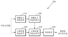
- the digital signal processing apparatus 100 illustrated in FIG. 1 includes a transform unit 110, an envelope obtainer 120, an envelope quantizer 130, an envelope encoder 140, a spectral normalizer 150, and a spectrum encoder. 160 may be included. Each component may be integrated into at least one or more modules and implemented as at least one or more processors (not shown).
- the digital signal may mean a media signal such as a video, an image, audio or voice, or a sound representing a mixed signal of audio and voice.
- the audio signal will be referred to for convenience of description.
- the converter 130 may generate an audio spectrum by converting an audio signal of a time domain into a frequency domain.
- the time / frequency domain transformation may be performed using various known methods such as Modified Discrete Cosine Transform (MDCT).
- MDCT Modified Discrete Cosine Transform
- Equation 1 Equation 1 below.
- N denotes the number of samples included in one frame, that is, frame size
- h j denotes an applied window
- s j denotes an audio signal in time domain
- x i denotes an MDCT conversion coefficient.
- a sine window for example, May be used.
- the conversion coefficients of the audio spectrum obtained from the conversion unit 110 for example, the MDCT coefficient x i are provided to the envelope acquisition unit 120.
- the envelope obtainer 120 may obtain an envelope value in units of a predetermined subband from the transform coefficients provided from the converter 110.
- the subband is a grouping of samples of the audio spectrum, and may have a uniform or nonuniform length reflecting a critical band. In the case of non-uniformity, the subband may be set such that the number of samples included in the subband increases from one sample to the last sample for one frame. In the case of supporting multiple bit rates, the number of samples included in each subband corresponding to different bit rates may be set to be the same. The number of subbands included in one frame or the number of samples included in the subbands may be predetermined.
- the envelope value may mean an average amplitude, average energy, power or norm value of the conversion coefficients included in the subband.
- An envelope value of each subband may be calculated based on Equation 2 below, but is not limited thereto.
- w denotes the number of transform coefficients included in the subband, that is, subband size
- x i denotes a transform coefficient
- n denotes an envelope value of the subband.
- the envelope quantization unit 130 may perform quantization on a logarithmic scale optimized for the envelope value n of each subband.
- the quantization index n q of the envelope value for each subband obtained from the envelope quantization unit 130 may be obtained by, for example, Equation 3 below.
- b is an initial value r / 2 before being optimized as a rounding coefficient.
- c is the base of the logarithmic scale, and r is the quantization resolution.
- the envelope quantization unit 130 may vary the left and right boundaries of the quantization region corresponding to each quantization index such that the total quantization error in the quantization region corresponding to each quantization index is minimized. To this end, the rounding coefficients b are adjusted such that the left and right quantization errors obtained between the left and right boundaries of the quantization region corresponding to each quantization index and the quantization index are equal. Detailed operations of the envelope quantization unit 130 will be described later.
- Equation 4 inverse quantization of the quantization index n q of the envelope value for each subband may be performed by Equation 4 below.
- r denotes a quantization resolution
- c denotes a base of a logarithmic scale.
- the quantization index (n q ) of the envelope value for each subband obtained by the envelope quantization unit 130 is the envelope encoder 140, and the dequantized envelope value (for each subband) ) May be provided to the spectral normalization unit 150.
- an envelope value obtained in each subband unit may be used for bit allocation required for encoding a normalized spectrum, that is, a normalized transform coefficient.
- an envelope value quantized and losslessly encoded in each subband unit may be included in a bitstream and provided to a decoding apparatus.
- an inverse quantized envelope value may be used so that the same process may be used in the encoding apparatus and the decoding apparatus.
- the masking threshold value may be calculated using the norm value for each subband unit, and the perceptually necessary number of bits may be predicted using the masking threshold value. That is, the masking threshold is a value corresponding to the Just Noticeable Distortion (JND), and when the quantization noise is smaller than the masking threshold, perceptual noise cannot be felt. Therefore, the minimum number of bits necessary to avoid perceptual noise can be calculated using the masking threshold.
- JND Just Noticeable Distortion
- a signal-to-mask ratio is calculated using a ratio between a norm value and a masking threshold value, and a masking threshold value is obtained by using a relationship of 6.025 dB ⁇ 1 bit with respect to the SMR. It is possible to predict the number of bits satisfying.
- the predicted number of bits is the minimum number of bits necessary to avoid perceptual noise, but in terms of compression, it is not necessary to use more than the predicted number of bits. Weak).
- the number of allowed bits of each subband may be expressed in decimal units, but is not limited thereto.
- bit allocation in each subband unit may be performed in decimal units using a norm value, but is not limited thereto.
- bits are sequentially allocated from subbands having a large norm value, so that more bits are allocated to perceptually important subbands by weighting the norm values of each subband according to the perceptual importance of each subband. I can adjust it.
- Perceptual importance can be determined, for example, by psychoacoustic weighting as in ITU-T G.719.
- the envelope encoder 140 obtains a quantization delta value with respect to the quantization index n q of the envelope value for each subband provided from the envelope quantization unit 130, and obtains a context for the quantization delta value. Lossless coding is performed based on the BER, and the result may be included in the bitstream to be used for transmission and storage. Here, the context may use the quantization delta value of the previous subband. Detailed operations of the envelope encoder 140 will be described later.
- the spectral normalizer 150 dequantizes the envelope value of each subband. Using By normalizing the transform coefficients as in Eq, the spectral mean energy of each subband is set to one.
- the spectral encoder 160 performs quantization and lossless coding on the normalized transform coefficient, and includes the result in a bitstream to use for transmission and storage.
- the spectrum encoder 160 may quantize and losslessly encode the normalized transform coefficient by using the allocated bit number finally determined based on the envelope value in each subband unit.
- Lossless coding for normalized transform coefficients may use, for example, Factorial Pulse Coding (hereinafter, referred to as FPC).
- FPC is a method of efficiently encoding an information signal using unit magnitude pulses.
- the information content can be represented by four components: the number of non-zero pulse positions, the position of non-zero pulses, the magnitude of non-zero pulses, and the sign of non-zero pulses.
- FPC Where m is the total number of unit magnitude pulses, and the original vector y and FPC vector of the subband Based on mean square error (MSE) We can determine the optimal solution for.
- MSE mean square error
- the optimal solution can be obtained by finding conditional extreme values using the Lagrangian function, as shown in Equation 5 below.
- L is the Lagrangian function
- m is the total number of unit-size pulses in the subband
- ⁇ is the Lagrange multiplier, which is an optimization factor
- y i is a normalized Denotes the optimal number of pulses required at position i.
- the entire set of each subband is obtained. May be included in the bitstream and transmitted.
- an optimal multiplier for minimizing the quantization error in each subband and performing alignment of the average energy may also be included in the bitstream and transmitted.
- the optimal multiplier can be obtained as in Equation 6 below.
- FIG. 2 is a block diagram showing the configuration of a digital signal decoding apparatus according to an embodiment of the present invention.
- the digital signal decoding apparatus 200 illustrated in FIG. 2 includes an envelope decoder 210, an envelope inverse quantizer 220, a spectrum decoder 230, a spectrum denormalizer 240, and an inverse transformer 250. can do.
- Each component may be integrated into at least one or more modules and implemented as at least one or more processors (not shown).
- the digital signal may mean a media signal such as a video, an image, audio or voice, or a sound representing a mixed signal of audio and voice.
- the audio signal will be referred to as corresponding to the encoding apparatus of FIG. 1. .
- the envelope decoder 210 receives a bitstream through a communication channel or a network, and losslessly decodes a quantization delta value of each subband included in the bitstream to quantize an envelope value for each subband. It is possible to restore the index n q .
- the envelope inverse quantization unit 220 performs inverse quantization on the quantization index n q of the decoded envelope value for each subband, thereby dequantizing the envelope value. Can be obtained.
- the spectrum decoder 230 may restore the normalized transform coefficient by performing lossless decoding and inverse quantization on the received bitstream. For example, if FPC is used in the encoder, the entire set of Can be lossless decoded and dequantized. In this case, the average energy alignment of each subband may be performed by Equation 7 using an optimal multiplier (G).
- G optimal multiplier
- the spectrum decoder 230 may perform lossless decoding and inverse quantization using an allocated number of bits finally determined based on an envelope value in each subband unit.
- the spectral denormalizer 240 performs denormalization on the normalized transform coefficient provided from the spectral decoder 210 by using the dequantized envelope value provided from the envelope dequantizer 220. Can be. For example, when FPC is used in the encoding apparatus, energy alignment is performed. Dequantized envelope value for Using Perform denormalization as shown in By performing denormalization, the original spectral average energy is restored for each subband.
- the inverse transform unit 250 may restore the audio signal in the time domain by performing an inverse transform on the transform coefficient provided from the spectral denormalization unit 240. For example, spectrum components using Equation 8 corresponding to Equation 1 below. The inverse transform may be performed on to obtain an audio signal s j in the time domain.
- the envelope quantization unit 130 quantizes the envelope value of each subband at a log scale whose base is c, the boundary B i of the quantization region corresponding to the quantization index is , Approximating points (A i ), or quantization indices, , Quantization resolution (r) ,
- the quantization step size Can be expressed as:
- the quantization index n q of the envelope value n for each subband may be obtained as in Equation 3 above.
- FIGS. 3A and 4A illustrate a signal-to-ratio (SNR) measure for quantization, that is, a quantization error, as shown in FIGS. 3A and 4A has different values for the left boundary and the right boundary from the approximation point.
- SNR signal-to-ratio
- 4A illustrates quantization of an unoptimized logarithmic scale (base is 2) with a quantization resolution of 1 and a quantization step size of 6.02 dB. It can be seen that the quantization errors SNR L and SNR R from the approximation point at the left and right boundaries of the quantization region differ from each other by 7.65 dB and 10.66 dB.
- the total quantization error in the quantization region corresponding to each quantization index may be minimized.
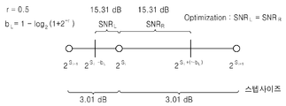
- the total quantization error in the quantization region may be minimum if the quantization errors obtained at the left and right boundaries of the quantization region from the approximation point are the same.
- the boundary shift of the quantization region can be obtained by varying the rounding coefficient b.
- the quantization errors SNR L and SNR R for the approximation point at the left and right boundaries of the quantization region corresponding to the quantization index may be represented by Equation 9 below.
- Exponential shifts for the left and right boundaries of the quantization region corresponding to the quantization index may be expressed by Equation 10 through parameters b L and b R.
- S i is an exponent for the boundary of the quantization region corresponding to the quantization index i
- b L and b R represent the exponential shift for the approximation point at the left and right boundaries of the quantization region, respectively.
- Equation 11 The sum of the exponential shifts for the approximation points at the left and right boundaries of the quantization region is equal to the quantization resolution, and thus can be expressed as Equation 11 below.
- Equation 9 may be expressed as Equation 12 below.
- the parameter b L can be determined as shown in Equation 13 below.
- Equation 14 the rounding coefficient b L may be expressed as Equation 14 below.
- 3B shows quantization of an optimized logarithmic scale (base is 2) with a quantization interval of 3.01 dB and a quantization resolution of 0.5. It can be seen that the quantization errors SNR L and SNR R from the approximation point at the left and right boundaries of the quantization region are equal to 15.31 dB.
- 4b shows quantization of an optimized logarithmic scale (base is 2) with a quantization interval of 6.02 dB and a quantization resolution of 1.0. It can be seen that the quantization errors SNR L and SNR R from the approximation point at the left and right boundaries of the quantization region are equal to 9.54 dB.
- bit rate-distortion function H (D) can be used as a reference for comparative analysis of various quantization methods.
- the entropy of the quantization index set can be regarded as bit rate, has dimension b / s, and the SNR of dB scale can be regarded as a distortion measure.
- 5A is a comparison graph in which quantization is performed on a normal distribution, in which a solid line represents a bit rate-distortion function for optimizing a log scale that is not optimized, and a dotted line represents a bit rate-distortion function for quantization of an optimized log scale.
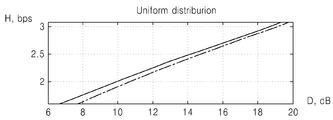
- 5B is a comparison graph in which quantization is performed on a uniform distribution, where the solid line represents the bit rate-distortion function for optimizing the log scale that is not optimized, and the dotted line represents the bit rate-distortion function for quantization of the optimized log scale. Samples of normal and uniform distributions are generated using a random number of sensors according to the corresponding law of distribution, zero expected value and single variance.
- the rate-distortion function H (D) can be calculated for various quantization resolutions. As shown in Figs. 5A and 5B, the dotted line is located under the solid line, which means that the performance of the optimized log scale quantization is superior to the non-optimized log scale quantization.
- quantization can be performed with less quantization error for the same bit rate, or quantization can be performed with fewer bits with the same quantization error for the same bit rate.
- Table 1 shows the unoptimized log scale quantization
- Table 2 shows the optimized log scale quantization, respectively.
- the characteristic value SNR is improved by 0.1 dB at quantization resolution 0.5, 0.45 dB at quantization resolution 1.0, and 1.5 dB at quantization resolution 2.0.
- the quantization method according to an embodiment does not increase complexity because only the lookup table of the quantization index needs to be updated according to the rounding coefficient.
- Context-based encoding of envelope values uses delta-coding.
- the quantization delta value for the envelope value between the current subband and the previous subband may be expressed as in Equation 16 below.
- d (i) is the quantization delta value for subband i + 1
- n q (i) is the quantization index of the envelope value for subband i
- n q (i + 1) is the subband ( i + 1) represents the quantization index of the envelope value.
- the quantization delta value d (i) for each subband is limited to the range [-15, 16]. First, a negative quantization delta value is adjusted as described below, and then a positive quantization delta value is adjusted.
- n q (0), d (0), d (1), d (2), ..., d (N-2) ) Is obtained.
- the quantization delta value of the current subband is encoded using a context model.
- the quantization delta value of the previous subband may be used as the context. Since n q (0) for the first subband exists in the range of [0,31], lossless coding is performed using 5 bits as it is.
- n q (0) for the first subband is used in the context of d (0), a value obtained by using a predetermined reference value from n q (0) can be used.
- d (i) when Huffman coding for d (i), d (i-1) may be used as the context, and when Huffman coding for d (0), n q (0) -reference value may be used as the context.
- a predetermined constant may be used, and may be set to an optimal value through simulation or experimentally in advance.
- the reference value may be included in the bitstream and transmitted, or may be previously provided to the encoding apparatus and the decoding apparatus.
- the envelope encoder 140 divides a range of quantization delta values of a previous subband used as a context into a plurality of groups, and quantizes the delta of the current subband based on a Huffman table predetermined for each group. Huffman coding on a value can be performed.
- the Huffman table may be generated through a training process using a large database, for example, may collect data based on a predetermined criterion, and generate the Huffman table based on the collected data.
- data about the frequency of the quantization delta value of the current subband may be collected to generate a Huffman table for each group.
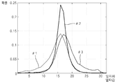
- probability distributions in three groups are shown in FIG. 6. It can be seen that the probability distributions of groups # 1 and # 3 are similar and are substantially inverted (or flipped) by the x-axis. This means that the same probabilistic model may be used for the two groups # 1 and # 3 without loss of coding efficiency. That is, group # 1 may use the same Huffman table as group # 3. Accordingly, Huffman table 1 for group # 2 and Huffman table 2 shared by group # 1 and group # 3 may be used. In this case, the index of the code for the group # 1 may be expressed in reverse with respect to the group # 3.
- the Huffman table for the quantization delta value of the current subband is determined as group # 1 based on the quantization delta value of the previous subband, which is the context, the quantization delta value d (i) of the current subband is inverted at the encoding end.
- the A value may be set to a value that makes the probability distributions of the group # 1 and the group # 3 symmetric.
- the A value is not extracted in the encoding and decoding process, and may be set to an optimum value in advance.
- the Huffman table of Group # 1 may be used instead of the Huffman table of Group # 3, and the quantization delta value may be changed in Group # 3.
- the A value may use 31.
- FIG. 7 illustrates a context-based Huffman encoding operation in the envelope encoder 140 of FIG. 1, using two Huffman tables determined by probability distributions of three groups of quantization delta values.
- the Huffman table 1 for group # 2 is used as a context
- the quantization delta value d (i-1) of the previous subband is used as the context.
- Huffman table 2 for and group # 3 is used.
- step 710 it is determined whether the quantization delta value d (i-1) of the previous subband belongs to group # 2.
- step 720 if the quantization delta value d (i-1) of the previous subband belongs to the group # 2 as a result of the determination in step 710, the quantization delta value d (i) of the current subband from the Huffman table 1. Select the code for.
- step 730 if the quantization delta value d (i-1) of the previous subband does not belong to group # 2 as a result of the determination in step 710, the quantization delta value d (i-1) of the previous subband is determined. It is determined whether it belongs to group # 1.
- step 740 when the quantization delta value d (i-1) of the previous subband does not belong to group # 1, that is, in group # 3, in step 730, the Huffman table 2 determines the current subband. Select the code for the quantization delta value d (i).
- step 750 if the quantization delta value d (i-1) of the previous subband belongs to group # 1 as a result of the determination in step 730, the quantization delta value d (i) of the current subband is inverted. Select a code for the quantization delta value d '(i) of the current subband inverted from Huffman table 2.
- Huffman encoding is performed on the quantization delta value d (i) of the current subband using the code selected in operation 720, 740, or 750.
- FIG. 8 is a diagram illustrating a context-based Huffman decoding operation of the envelope decoder 210 of FIG. 2 and uses two Huffman tables determined by probability distributions of three groups of quantization delta values as in FIG. 7.
- the quantization delta value d (i) of the current subband the Huffman table 1 for group # 2 is used as the context, and the quantization delta value d (i-1) of the previous subband is used as the context.
- Huffman table 2 for and group # 3 is used.
- step 810 it is determined whether the quantization delta value d (i-1) of the previous subband belongs to group # 2.
- step 820 when the quantization delta value d (i-1) of the previous subband belongs to the group # 2 as a result of the determination in step 810, the quantization delta value d (i) of the current subband from the Huffman table 1. Select the code for.
- step 830 when the quantization delta value d (i-1) of the previous subband does not belong to the group # 2 as a result of the determination in step 810, the quantization delta value d (i-1) of the previous subband is determined. It is determined whether it belongs to group # 1.
- step 840 when the quantization delta value d (i-1) of the previous subband does not belong to group # 1, that is, when belonging to group # 3, in step 830, the Huffman table 2 determines the current subband. Select the code for the quantization delta value d (i).
- step 850 if the quantization delta value d (i-1) of the previous subband belongs to the group # 1, in step 830, the quantization delta value d (i) of the current subband is inverted. Select a code for the quantization delta value d '(i) of the current subband inverted from Huffman table 2.
- step 860 Huffman decoding is performed on the quantization delta value d (i) of the current subband using the code selected in steps 820, 840, or 850.
- FIG. 9 is a block diagram illustrating a configuration of a multimedia apparatus including an encoding module according to an embodiment of the present invention.
- the multimedia apparatus 900 illustrated in FIG. 9 may include a communication unit 910 and an encoding module 930.
- the storage unit 950 may further include an audio bitstream according to the use of the audio bitstream obtained as a result of the encoding.
- the multimedia device 900 may further include a microphone 970. That is, the storage unit 950 and the microphone 970 may be provided as an option.
- the multimedia device 900 illustrated in FIG. 9 may further include an arbitrary decoding module (not shown), for example, a decoding module for performing a general decoding function or a decoding module according to an embodiment of the present invention.
- the encoding module 930 may be integrated with other components (not shown) included in the multimedia device 900 and implemented as at least one or more processors (not shown).
- the communication unit 910 may receive at least one of audio and an encoded bitstream provided from the outside, or may transmit at least one of reconstructed audio and an audio bitstream obtained as a result of encoding of the encoding module 930. Can be.
- the communication unit 910 includes wireless Internet, wireless intranet, wireless telephone network, wireless LAN (LAN), Wi-Fi, Wi-Fi Direct (WFD), 3G (Generation), 4G (4 Generation), and Bluetooth.
- Wireless networks such as Bluetooth, Infrared Data Association (IrDA), Radio Frequency Identification (RFID), Ultra WideBand (UWB), Zigbee, Near Field Communication (NFC), wired telephone networks, wired Internet It is configured to send and receive data with external multimedia device through wired network.
- the encoding module 930 converts an audio signal of a time domain provided through the communication unit 910 or the microphone 970 into an audio spectrum of a frequency domain, and, for each subband, Obtains a low envelope, performs quantization on the envelope in units of subbands, obtains a difference value between quantized envelopes of adjacent subbands, and uses a difference value of a previous subband as a context to make a difference in the current subband.
- a bitstream may be generated by performing lossless encoding on a value.
- the encoding module 930 adjusts a boundary of the quantization region so that the total quantization error in the quantization region corresponding to a predetermined quantization index is minimized when the envelope is quantized, and is updated therefrom. Quantization can be performed using.
- the storage unit 950 may store the encoded bitstream generated by the encoding module 930. On the other hand, the storage unit 950 may store various programs necessary for the operation of the multimedia device 900.
- the microphone 970 may provide a user or an external audio signal to the encoding module 930.
- FIG. 10 is a block diagram showing a configuration of a multimedia device including a decoding module according to an embodiment of the present invention.
- the multimedia apparatus 1000 illustrated in FIG. 10 may include a communication unit 1010 and a decoding module 1030.
- the storage unit 1050 may further include a storage unit 1050 for storing the restored audio signal according to the use of the restored audio signal obtained as a result of the decoding.
- the multimedia apparatus 1000 may further include a speaker 1070. That is, the storage unit 1050 and the speaker 1070 may be provided as an option.
- the multimedia apparatus 1000 illustrated in FIG. 10 may further include an arbitrary encoding module (not shown), for example, an encoding module for performing a general encoding function or an encoding module according to an embodiment of the present invention.
- the decoding module 1030 may be integrated with other components (not shown) included in the multimedia apparatus 1000 and implemented as at least one or more processors (not shown).
- the communication unit 1010 receives at least one of an encoded bitstream and an audio signal provided from the outside or at least one of a reconstructed audio signal obtained as a result of decoding of the decoding module 1030 and an audio bitstream obtained as a result of encoding. You can send one. Meanwhile, the communication unit 1010 may be implemented substantially similarly to the communication unit 910 of FIG. 9.
- the decoding module 1030 may receive a bitstream provided through the communication unit 1010, obtain a difference value between quantized envelopes of adjacent subbands from the bitstream, and obtain a difference value of a previous subband.
- Lossless decoding may be performed on a difference value of a current subband using a context, and dequantization may be performed by obtaining the quantized envelope in subband units from a difference value of a current subband restored as a result of lossless decoding.
- the storage unit 1050 may store the restored audio signal generated by the decoding module 1030. Meanwhile, the storage unit 1050 may store various programs necessary for operating the multimedia apparatus 1000.
- the speaker 1070 may output the restored audio signal generated by the decoding module 1030 to the outside.
- FIG. 11 is a block diagram illustrating a configuration of a multimedia apparatus including an encoding module and a decoding module according to an embodiment of the present invention.
- the multimedia device 1100 illustrated in FIG. 11 may include a communication unit 1110, an encoding module 1120, and a decoding module 1130.
- the storage unit 1140 may further include an audio bitstream or a restored audio signal according to a use of the audio bitstream obtained from the encoding or the restored audio signal obtained as the decoding result.
- the multimedia device 1100 may further include a microphone 1150 or a speaker 1160.
- the encoding module 1120 and the decoding module 1130 may be integrated with other components (not shown) included in the multimedia device 1100 and implemented as at least one processor (not shown).
- FIG. 11 overlaps with the components of the multimedia apparatus 900 illustrated in FIG. 9 or the components of the multimedia apparatus 1000 illustrated in FIG. 10, and thus a detailed description thereof will be omitted.
- a broadcast or music dedicated device including a voice communication terminal including a telephone, a mobile phone, a TV, an MP3 player, or the like, or a voice communication dedicated
- the terminal may include a fusion terminal device of a broadcasting or music dedicated device, but is not limited thereto.
- the multimedia device 900, 1000, 1100 may be used as a client, a server, or a transducer disposed between the client and the server.
- the multimedia device (900, 1000, 1100) is a mobile phone, for example, although not shown, a user input unit such as a keypad, a display unit for displaying information processed in the user interface or mobile phone, controls the overall functions of the mobile phone It may further include a processor.
- the mobile phone may further include a camera unit having an imaging function and at least one component that performs a function required by the mobile phone.
- the multimedia device (900, 1000, 1100) is a TV, for example, although not shown, further comprising a user input unit, such as a keypad, a display unit for displaying the received broadcast information, a processor for controlling the overall functions of the TV Can be.
- the TV may further include at least one or more components that perform a function required by the TV.
- the method according to the embodiments can be written in a computer executable program and can be implemented in a general-purpose digital computer operating the program using a computer readable recording medium.
- data structures, program instructions, or data files that can be used in the above-described embodiments of the present invention may be recorded on a computer-readable recording medium through various means.
- the computer-readable recording medium may include all kinds of storage devices in which data that can be read by a computer system is stored. Examples of computer-readable recording media include magnetic media, such as hard disks, floppy disks, and magnetic tape, optical media such as CD-ROMs, DVDs, floppy disks, and the like.
- Such as magneto-optical media, and hardware devices specifically configured to store and execute program instructions such as ROM, RAM, flash memory, and the like.
- the computer-readable recording medium may also be a transmission medium for transmitting a signal specifying a program command, a data structure, or the like.
- Examples of program instructions may include high-level language code that can be executed by a computer using an interpreter as well as machine code generated by a compiler.
Landscapes
- Engineering & Computer Science (AREA)
- Physics & Mathematics (AREA)
- Computational Linguistics (AREA)
- Signal Processing (AREA)
- Health & Medical Sciences (AREA)
- Audiology, Speech & Language Pathology (AREA)
- Human Computer Interaction (AREA)
- Acoustics & Sound (AREA)
- Multimedia (AREA)
- Spectroscopy & Molecular Physics (AREA)
- Mathematical Physics (AREA)
- Compression, Expansion, Code Conversion, And Decoders (AREA)
Abstract
Description


| 양자화 해상도 (r) | 2.0 | 1.0 | 0.5 |
| 라운딩 계수 (b/r) | 0.5 | 0.5 | 0.5 |
| 정상 분포 | |||
| 비트레이트 (H), b/s | 1.6179 | 2.5440 | 3.5059 |
| 양자화 오차 (D), dB | 6.6442 | 13.8439 | 19.9534 |
| 균일 분포 | |||
| 비트레이트 (H), b/s | 1.6080 | 2.3227 | 3.0830 |
| 양자화 오차 (D), dB | 6.6470 | 12.5018 | 19.3640 |
| 양자화 해상도 (r) | 2.0 | 1.0 | 0.5 |
| 라운딩 계수 (b/r) | 0.3390 | 0.4150 | 0.4569 |
| 정상 분포 | |||
| 비트레이트 (H), b/s | 1.6069 | 2.5446 | 3.5059 |
| 양자화 오차 (D), dB | 8.2404 | 14.2284 | 20.0495 |
| 균일 분포 | |||
| 비트레이트 (H), b/s | 1.6345 | 2.3016 | 3.0449 |
| 양자화 오차 (D), dB | 7.9208 | 12.8954 | 19.4922 |
| 그룹 번호 | 차이값의 하한 | 차이값의 상한 |
| #1 | 0 | 12 |
| #2 | 13 | 17 |
| #3 | 18 | 31 |
| 알고리즘 | 비트율, kbps | 이득, % |
| 허프만 엔코딩 | 6.25 | - |
| 컨텍스트+허프만 엔코딩 | 5.7 | 9 |
Claims (25)
- 오디오 스펙트럼에 대하여, 소정의 서브밴드 단위로 엔벨로프를 획득하는 단계;상기 서브밴드 단위로, 상기 엔벨로프에 대하여 양자화하는 단계; 및인접한 서브밴드에 대하여 양자화된 엔벨로프간의 차이값을 구하고, 이전 서브밴드의 차이값을 컨텍스트로 사용하여 현재 서브밴드의 차이값에 대하여 무손실 부호화를 수행하는 단계를 포함하는 오디오 부호화방법.
- 제1 항에 있어서, 상기 양자화 단계에서는, 소정의 양자화 인덱스에 대응하는 양자화 영역에서의 전체 양자화오차가 최소가 되도록 상기 양자화 영역의 경계를 조정하는 오디오 부호화방법.
- 제1 항에 있어서, 상기 엔벨로프는 상기 서브밴드의 평균 에너지, 평균 진폭, 파워 및 norm 값 중 어느 하나인 오디오 부호화방법.
- 제1 항에 있어서, 상기 무손실 부호화단계에서는, 상기 인접한 서브밴드에 대하여 양자화된 엔벨로프간의 차이값이 특정 범위를 갖도록 조정하는 오디오 부호화방법.
- 제1 항에 있어서, 상기 무손실 부호화단계에서는, 상기 이전 서브밴드의 차이값의 범위를 복수개의 그룹으로 나누고, 각 그룹별로 미리 정해진 허프만 테이블을 이용하여 상기 현재 서브밴드의 차이값에 대한 허프만 부호화를 수행하는 오디오 부호화방법.
- 제5 항에 있어서, 상기 무손실 부호화단계에서는, 상기 이전 서브밴드의 차이값의 범위를 제1 내지 제3 그룹으로 나누고, 상기 제1 내지 제3 그룹에 대하여 단독의 제1 허프만 테이블과 공유의 제2 허프만 테이블을 포함하는 2개의 허프만 테이블을 할당하는 오디오 부호화방법.
- 제6 항에 있어서, 상기 무손실 부호화단계에서는, 상기 제2 허프만 테이블을 공유하는 경우, 상기 현재 서브밴드의 차이값을 그대로 이용하거나, 반전처리하여 이용하는 오디오 부호화방법.
- 제1 항에 있어서, 상기 무손실 부호화단계에서는, 이전 서브밴드가 존재하지 않는 첫번째 서브밴드에 대해서는 상기 양자화된 엔벨로프를 그대로 무손실 부호화하고, 컨텍스트로 사용되는 경우에는 소정의 기준값에 의해 얻어지는 차이값을 이용하는 오디오 부호화방법.
- 오디오 스펙트럼에 대하여, 소정의 서브밴드 단위로 엔벨로프를 획득하는 엔벨로프 획득부;상기 서브밴드 단위로, 상기 엔벨로프에 대하여 양자화하는 엔벨로프 양자화부;인접한 서브밴드에 대하여 양자화된 엔벨로프간의 차이값을 구하고, 이전 서브밴드의 차이값을 컨텍스트로 사용하여 현재 서브밴드의 차이값에 대하여 무손실 부호화를 수행하는 엔벨로프 부호화부;상기 오디오 스펙트럼에 대하여 양자화 및 무손실 부호화를 수행하는 스펙트럼 부호화부를 포함하는 오디오 부호화장치.
- 제9 항에 있어서, 상기 오디오 스펙트럼에 대하여 상기 서브밴드 단위로 엔벨로프를 이용하여 정규화를 수행하고, 정규화된 오디오 스펙트럼을 상기 스펙트럼 부호화부로 제공하는 스펙트럼 정규화부를 더 포함하는 오디오 부호화장치.
- 제9 항에 있어서, 상기 스펙트럼 부호화부는 팩토리얼 펄스 코딩에 의해 무손실 부호화를 수행하는 오디오 부호화장치.
- 비트스트림으로부터 인접한 서브밴드에 대하여 양자화된 엔벨로프간의 차이값을 구하고, 이전 서브밴드의 차이값을 컨텍스트로 사용하여 현재 서브밴드의 차이값에 대하여 무손실 복호화를 수행하는 단계; 및상기 무손실 복호화결과 복원된 현재 서브밴드의 차이값으로부터 서브밴드 단위로 상기 양자화된 엔벨로프를 구하여 역양자화를 수행하는 단계를 포함하는 오디오 복호화방법.
- 제12 항에 있어서, 상기 엔벨로프는 상기 서브밴드의 평균 에너지, 평균 진폭, 파워 및 norm 값 중 어느 하나인 오디오 복호화방법.
- 제12 항에 있어서, 상기 무손실 복호화단계에서는, 상기 이전 서브밴드의 차이값의 범위를 복수개의 그룹으로 나누고, 각 그룹별로 미리 정해진 허프만 테이블을 이용하여 상기 현재 서브밴드의 차이값에 대한 허프만 복호화를 수행하는 오디오 복호화방법.
- 제14 항에 있어서, 상기 무손실 복호화단계에서는, 상기 이전 서브밴드의 차이값의 범위를 제1 내지 제3 그룹으로 나누고, 상기 제1 내지 제3 그룹에 대하여 단독의 제1 허프만 테이블과 공유의 제2 허프만 테이블을 포함하는 2개의 허프만 테이블을 할당하는 오디오 복호화방법.
- 제15 항에 있어서, 상기 무손실 부호화단계에서는, 상기 제2 허프만 테이블을 공유하는 경우, 상기 현재 서브밴드의 차이값을 그대로 이용하거나, 반전처리하여 이용하는 오디오 복호화방법.
- 제12 항에 있어서, 상기 무손실 복호화단계에서는, 이전 서브밴드가 존재하지 않는 첫번째 서브밴드에 대해서는 상기 양자화된 엔벨로프를 그대로 무손실 복호화하고, 컨텍스트로 사용되는 경우에는 소정의 기준값에 의해 얻어지는 차이값을 이용하는 오디오 복호화방법.
- 비트스트림으로부터 인접한 서브밴드에 대하여 양자화된 엔벨로프간의 차이값을 구하고, 이전 서브밴드의 차이값을 컨텍스트로 사용하여 현재 서브밴드의 차이값에 대하여 무손실 복호화를 수행하는 엔벨로프 복호화부;상기 무손실 복호화결과 복원된 현재 서브밴드의 차이값으로부터 서브밴드 단위로 상기 양자화된 엔벨로프를 구하여 역양자화를 수행하는 엔벨로프 역양자화부; 및상기 비트스트림에 포함된 스펙트럼 성분에 대하여 무손실 복호화 및 역양자화를 수행하는 스펙트럼 복호화부를 포함하는 오디오 복호화장치.
- 제18 항에 있어서, 상기 역양자화된 스펙트럼 성분에 대하여 상기 서브밴드 단위로 엔벨로프를 이용하여 역정규화를 수행하는 스펙트럼 역정규화부를 더 포함하는 오디오 복호화장치.
- 제18 항에 있어서, 스펙트럼 복호화부는 팩토리얼 펄스 디코딩에 의해 무손실 복호화를 수행하는 오디오 복호화장치.
- 오디오 스펙트럼에 대하여, 소정의 서브밴드 단위로 엔벨로프를 획득하고, 상기 서브밴드 단위로, 상기 엔벨로프에 대하여 양자화하고, 인접한 서브밴드에 대하여 양자화된 엔벨로프간의 차이값을 구하고, 이전 서브밴드의 차이값을 컨텍스트로 사용하여 현재 서브밴드의 차이값에 대하여 무손실 부호화를 수행하는 부호화모듈을 포함하는 멀티미디어 기기.
- 비트스트림으로부터 인접한 서브밴드에 대하여 양자화된 엔벨로프간의 차이값을 구하고, 이전 서브밴드의 차이값을 컨텍스트로 사용하여 현재 서브밴드의 차이값에 대하여 무손실 복호화를 수행하고, 상기 무손실 복호화결과 복원된 현재 서브밴드의 차이값으로부터 서브밴드 단위로 상기 양자화된 엔벨로프를 구하여 역양자화를 수행하는 복호화모듈을 포함하는 멀티미디어 기기.
- 오디오 스펙트럼에 대하여, 소정의 서브밴드 단위로 엔벨로프를 획득하고, 상기 서브밴드 단위로, 상기 엔벨로프에 대하여 양자화하고, 인접한 서브밴드에 대하여 양자화된 엔벨로프간의 차이값을 구하고, 이전 서브밴드의 차이값을 컨텍스트로 사용하여 현재 서브밴드의 차이값에 대하여 무손실 부호화를 수행하는 부호화모듈; 및비트스트림으로부터 인접한 서브밴드에 대하여 양자화된 엔벨로프간의 차이값을 구하고, 이전 서브밴드의 차이값을 컨텍스트로 사용하여 현재 서브밴드의 차이값에 대하여 무손실 복호화를 수행하고, 상기 무손실 복호화결과 복원된 현재 서브밴드의 차이값으로부터 서브밴드 단위로 상기 양자화된 엔벨로프를 구하여 역양자화를 수행하는 복호화모듈을 포함하는 멀티미디어 기기.
- 청구항 1에 기재된 오디오 부호화방법을 컴퓨터에서 실행시킬 수 있는 프로그램을 기록한 컴퓨터로 읽을 수 있는 기록매체.
- 청구항 12에 기재된 오디오 복호화방법을 컴퓨터에서 실행시킬 수 있는 프로그램을 기록한 컴퓨터로 읽을 수 있는 기록매체.
Priority Applications (13)
| Application Number | Priority Date | Filing Date | Title |
|---|---|---|---|
| MX2013014152A MX2013014152A (es) | 2011-06-01 | 2012-06-01 | Metodo y aparato de codificacion de audio, metodo y aparato de decodificacion de audio, medio de grabacion de los mismos y dispositivo multimedia que emplea los mismos. |
| CA2838170A CA2838170C (en) | 2011-06-01 | 2012-06-01 | Audio-encoding method and apparatus, audio-decoding method and apparatus, recoding medium thereof, and multimedia device employing same |
| AU2012263093A AU2012263093B2 (en) | 2011-06-01 | 2012-06-01 | Audio-encoding method and apparatus, audio-decoding method and apparatus, recording medium thereof, and multimedia device employing same |
| MX2015014526A MX357875B (es) | 2011-06-01 | 2012-06-01 | Método y aparato de codificación de audio, método y aparato de decodificacion de audio, medio de grabación de los mismos y dispositivo multimedia que emplea los mismos. |
| PL12791983T PL2717264T3 (pl) | 2011-06-01 | 2012-06-01 | Bazujące na pod-paśmie kodowanie obwiedni sygnału audio |
| EP12791983.5A EP2717264B1 (en) | 2011-06-01 | 2012-06-01 | Sub-band-based encoding of the envelope of an audio signal |
| CN201280037719.1A CN103733257B (zh) | 2011-06-01 | 2012-06-01 | 音频编码方法和设备、音频解码方法和设备和采用音频编码方法和设备、音频解码方法和设备的多媒体装置 |
| US14/123,359 US9361895B2 (en) | 2011-06-01 | 2012-06-01 | Audio-encoding method and apparatus, audio-decoding method and apparatus, recoding medium thereof, and multimedia device employing same |
| JP2014513447A JP6262649B2 (ja) | 2011-06-01 | 2012-06-01 | オーディオ符号化方法及び記録媒体 |
| US15/142,594 US9589569B2 (en) | 2011-06-01 | 2016-04-29 | Audio-encoding method and apparatus, audio-decoding method and apparatus, recoding medium thereof, and multimedia device employing same |
| AU2016256685A AU2016256685B2 (en) | 2011-06-01 | 2016-11-08 | Audio-encoding method and apparatus, audio-decoding method and apparatus, recording medium thereof, and multimedia device employing same |
| US15/450,672 US9858934B2 (en) | 2011-06-01 | 2017-03-06 | Audio-encoding method and apparatus, audio-decoding method and apparatus, recoding medium thereof, and multimedia device employing same |
| AU2017228519A AU2017228519B2 (en) | 2011-06-01 | 2017-09-11 | Audio-encoding method and apparatus, audio-decoding method and apparatus, recording medium thereof, and multimedia device employing same |
Applications Claiming Priority (2)
| Application Number | Priority Date | Filing Date | Title |
|---|---|---|---|
| RU2011-121982 | 2011-06-01 | ||
| RU2011121982/08A RU2464649C1 (ru) | 2011-06-01 | 2011-06-01 | Способ обработки звукового сигнала |
Related Child Applications (2)
| Application Number | Title | Priority Date | Filing Date |
|---|---|---|---|
| US14/123,359 A-371-Of-International US9361895B2 (en) | 2011-06-01 | 2012-06-01 | Audio-encoding method and apparatus, audio-decoding method and apparatus, recoding medium thereof, and multimedia device employing same |
| US15/142,594 Continuation US9589569B2 (en) | 2011-06-01 | 2016-04-29 | Audio-encoding method and apparatus, audio-decoding method and apparatus, recoding medium thereof, and multimedia device employing same |
Publications (2)
| Publication Number | Publication Date |
|---|---|
| WO2012165910A2 true WO2012165910A2 (ko) | 2012-12-06 |
| WO2012165910A3 WO2012165910A3 (ko) | 2013-03-28 |
Family
ID=47145534
Family Applications (1)
| Application Number | Title | Priority Date | Filing Date |
|---|---|---|---|
| PCT/KR2012/004362 WO2012165910A2 (ko) | 2011-06-01 | 2012-06-01 | 오디오 부호화방법 및 장치, 오디오 복호화방법 및 장치, 그 기록매체 및 이를 채용하는 멀티미디어 기기 |
Country Status (12)
| Country | Link |
|---|---|
| US (3) | US9361895B2 (ko) |
| EP (1) | EP2717264B1 (ko) |
| JP (2) | JP6262649B2 (ko) |
| KR (2) | KR102044006B1 (ko) |
| CN (3) | CN103733257B (ko) |
| AU (3) | AU2012263093B2 (ko) |
| CA (1) | CA2838170C (ko) |
| MX (2) | MX2013014152A (ko) |
| PL (1) | PL2717264T3 (ko) |
| RU (1) | RU2464649C1 (ko) |
| TW (3) | TWI616869B (ko) |
| WO (1) | WO2012165910A2 (ko) |
Cited By (2)
| Publication number | Priority date | Publication date | Assignee | Title |
|---|---|---|---|---|
| CN106463133A (zh) * | 2014-03-24 | 2017-02-22 | 三星电子株式会社 | 高频带编码方法和装置,以及高频带解码方法和装置 |
| US11676614B2 (en) | 2014-03-03 | 2023-06-13 | Samsung Electronics Co., Ltd. | Method and apparatus for high frequency decoding for bandwidth extension |
Families Citing this family (24)
| Publication number | Priority date | Publication date | Assignee | Title |
|---|---|---|---|---|
| RU2464649C1 (ru) * | 2011-06-01 | 2012-10-20 | Корпорация "САМСУНГ ЭЛЕКТРОНИКС Ко., Лтд." | Способ обработки звукового сигнала |
| KR102070429B1 (ko) | 2011-10-21 | 2020-01-28 | 삼성전자주식회사 | 에너지 무손실 부호화방법 및 장치, 오디오 부호화방법 및 장치, 에너지 무손실 복호화방법 및 장치, 및 오디오 복호화방법 및 장치 |
| GB2508417B (en) * | 2012-11-30 | 2017-02-08 | Toshiba Res Europe Ltd | A speech processing system |
| CN108198564B (zh) | 2013-07-01 | 2021-02-26 | 华为技术有限公司 | 信号编码和解码方法以及设备 |
| TWI579831B (zh) | 2013-09-12 | 2017-04-21 | 杜比國際公司 | 用於參數量化的方法、用於量化的參數之解量化方法及其電腦可讀取的媒體、音頻編碼器、音頻解碼器及音頻系統 |
| EP3660843B1 (en) | 2013-09-13 | 2022-11-09 | Samsung Electronics Co., Ltd. | Lossless coding method |
| WO2015037961A1 (ko) * | 2013-09-13 | 2015-03-19 | 삼성전자 주식회사 | 에너지 무손실 부호화방법 및 장치, 신호 부호화방법 및 장치, 에너지 무손실 복호화방법 및 장치, 및 신호 복호화방법 및 장치 |
| EP3046104B1 (en) * | 2013-09-16 | 2019-11-20 | Samsung Electronics Co., Ltd. | Signal encoding method and signal decoding method |
| MX357135B (es) | 2013-10-18 | 2018-06-27 | Fraunhofer Ges Forschung | Codificación de coeficientes espectrales de un espectro de una señal de audio. |
| EP3975173B1 (en) | 2013-12-02 | 2024-01-17 | Top Quality Telephony, Llc | A computer-readable storage medium and a computer software product |
| EP3176780A4 (en) | 2014-07-28 | 2018-01-17 | Samsung Electronics Co., Ltd. | Signal encoding method and apparatus and signal decoding method and apparatus |
| GB2526636B (en) * | 2014-09-19 | 2016-10-26 | Gurulogic Microsystems Oy | Encoder, decoder and methods employing partial data encryption |
| US10553228B2 (en) * | 2015-04-07 | 2020-02-04 | Dolby International Ab | Audio coding with range extension |
| CN104966517B (zh) * | 2015-06-02 | 2019-02-01 | 华为技术有限公司 | 一种音频信号增强方法和装置 |
| CN108432248A (zh) * | 2015-11-22 | 2018-08-21 | Lg电子株式会社 | 用于对视频信号进行熵编码和解码的方法和设备 |
| US11817111B2 (en) | 2018-04-11 | 2023-11-14 | Dolby Laboratories Licensing Corporation | Perceptually-based loss functions for audio encoding and decoding based on machine learning |
| US10586546B2 (en) | 2018-04-26 | 2020-03-10 | Qualcomm Incorporated | Inversely enumerated pyramid vector quantizers for efficient rate adaptation in audio coding |
| US10573331B2 (en) * | 2018-05-01 | 2020-02-25 | Qualcomm Incorporated | Cooperative pyramid vector quantizers for scalable audio coding |
| US10580424B2 (en) * | 2018-06-01 | 2020-03-03 | Qualcomm Incorporated | Perceptual audio coding as sequential decision-making problems |
| US10734006B2 (en) | 2018-06-01 | 2020-08-04 | Qualcomm Incorporated | Audio coding based on audio pattern recognition |
| CN109473116B (zh) * | 2018-12-12 | 2021-07-20 | 思必驰科技股份有限公司 | 语音编码方法、语音解码方法及装置 |
| CN110400578B (zh) * | 2019-07-19 | 2022-05-17 | 广州市百果园信息技术有限公司 | 哈希码的生成及其匹配方法、装置、电子设备和存储介质 |
| RU2769618C2 (ru) * | 2020-05-18 | 2022-04-04 | ОБЩЕСТВО С ОГРАНИЧЕННОЙ ОТВЕТСТВЕННОСТЬЮ "СберМедИИ" | Способ уменьшения вклада технических факторов в суммарный сигнал данных масс-спектрометрии с помощью фильтрации по техническим образцам |
| KR102660883B1 (ko) * | 2023-12-01 | 2024-04-25 | 주식회사 테스트웍스 | 임베디드 장치의 미디어 프로세싱 테스트 방법 및 이를 수행하는 컴퓨팅 장치 |
Citations (3)
| Publication number | Priority date | Publication date | Assignee | Title |
|---|---|---|---|---|
| JP2000132193A (ja) * | 1998-10-22 | 2000-05-12 | Sony Corp | 信号符号化装置及び方法、並びに信号復号装置及び方法 |
| KR20060060928A (ko) * | 2004-12-01 | 2006-06-07 | 삼성전자주식회사 | 주파수 대역간의 유사도를 이용한 오디오 신호 처리 장치및 방법 |
| US20100228541A1 (en) * | 2005-11-30 | 2010-09-09 | Matsushita Electric Industrial Co., Ltd. | Subband coding apparatus and method of coding subband |
Family Cites Families (41)
| Publication number | Priority date | Publication date | Assignee | Title |
|---|---|---|---|---|
| CA1336841C (en) * | 1987-04-08 | 1995-08-29 | Tetsu Taguchi | Multi-pulse type coding system |
| JP3013698B2 (ja) * | 1994-04-20 | 2000-02-28 | 松下電器産業株式会社 | ベクトル量子化符号化装置と復号化装置 |
| US5687191A (en) * | 1995-12-06 | 1997-11-11 | Solana Technology Development Corporation | Post-compression hidden data transport |
| US5924064A (en) * | 1996-10-07 | 1999-07-13 | Picturetel Corporation | Variable length coding using a plurality of region bit allocation patterns |
| US8024269B1 (en) * | 1997-08-27 | 2011-09-20 | Datatreasury Corporation | Remote image capture with centralized processing and storage |
| JP3323175B2 (ja) * | 1999-04-20 | 2002-09-09 | 松下電器産業株式会社 | 符号化装置 |
| US6978236B1 (en) * | 1999-10-01 | 2005-12-20 | Coding Technologies Ab | Efficient spectral envelope coding using variable time/frequency resolution and time/frequency switching |
| JP3559485B2 (ja) * | 1999-11-22 | 2004-09-02 | 日本電信電話株式会社 | 音声信号の後処理方法および装置並びにプログラムを記録した記録媒体 |
| JP2002268693A (ja) * | 2001-03-12 | 2002-09-20 | Mitsubishi Electric Corp | オーディオ符号化装置 |
| EP1386310A1 (en) | 2001-05-11 | 2004-02-04 | Matsushita Electric Industrial Co., Ltd. | Device to encode, decode and broadcast audio signal with reduced size spectral information |
| US6934676B2 (en) * | 2001-05-11 | 2005-08-23 | Nokia Mobile Phones Ltd. | Method and system for inter-channel signal redundancy removal in perceptual audio coding |
| JP2003029797A (ja) * | 2001-05-11 | 2003-01-31 | Matsushita Electric Ind Co Ltd | 符号化装置、復号化装置および放送システム |
| US7200561B2 (en) * | 2001-08-23 | 2007-04-03 | Nippon Telegraph And Telephone Corporation | Digital signal coding and decoding methods and apparatuses and programs therefor |
| EP1701340B1 (en) * | 2001-11-14 | 2012-08-29 | Panasonic Corporation | Decoding device, method and program |
| JP2003233397A (ja) * | 2002-02-12 | 2003-08-22 | Victor Co Of Japan Ltd | オーディオ符号化装置、オーディオ符号化プログラム及びオーディオ符号化データ伝送装置 |
| KR100462611B1 (ko) * | 2002-06-27 | 2004-12-20 | 삼성전자주식회사 | 하모닉 성분을 이용한 오디오 코딩방법 및 장치 |
| US7433824B2 (en) | 2002-09-04 | 2008-10-07 | Microsoft Corporation | Entropy coding by adapting coding between level and run-length/level modes |
| JP4728568B2 (ja) * | 2002-09-04 | 2011-07-20 | マイクロソフト コーポレーション | レベル・モードとラン・レングス/レベル・モードの間での符号化を適応させるエントロピー符号化 |
| KR100754439B1 (ko) * | 2003-01-09 | 2007-08-31 | 와이더댄 주식회사 | 이동 전화상의 체감 음질을 향상시키기 위한 디지털오디오 신호의 전처리 방법 |
| CN1898724A (zh) | 2003-12-26 | 2007-01-17 | 松下电器产业株式会社 | 语音/乐音编码设备及语音/乐音编码方法 |
| KR100771401B1 (ko) * | 2005-08-01 | 2007-10-30 | (주)펄서스 테크놀러지 | 프로그래머블 프로세서에서 mpeg-2 또는 mpeg-4aac 오디오 복호 알고리즘을 처리하기 위한 연산 회로및 연산 방법 |
| BRPI0520729B1 (pt) * | 2005-11-04 | 2019-04-02 | Nokia Technologies Oy | Método para a codificação e decodificação de sinais de áudio, codificador para codificação e decodificador para decodificar sinais de áudio e sistema para compressão de áudio digital. |
| RU2420816C2 (ru) * | 2006-02-24 | 2011-06-10 | Франс Телеком | Способ двоичного кодирования показателей квантования огибающей сигнала, способ декодирования огибающей сигнала и соответствующие модули кодирования и декодирования |
| DE602007004502D1 (de) * | 2006-08-15 | 2010-03-11 | Broadcom Corp | Neuphasierung des status eines dekodiergerätes nach einem paketverlust |
| KR101346358B1 (ko) * | 2006-09-18 | 2013-12-31 | 삼성전자주식회사 | 대역폭 확장 기법을 이용한 오디오 신호의 부호화/복호화방법 및 장치 |
| JP4823001B2 (ja) * | 2006-09-27 | 2011-11-24 | 富士通セミコンダクター株式会社 | オーディオ符号化装置 |
| US7953595B2 (en) * | 2006-10-18 | 2011-05-31 | Polycom, Inc. | Dual-transform coding of audio signals |
| US20080243518A1 (en) * | 2006-11-16 | 2008-10-02 | Alexey Oraevsky | System And Method For Compressing And Reconstructing Audio Files |
| KR100895100B1 (ko) * | 2007-01-31 | 2009-04-28 | 엠텍비젼 주식회사 | 디지털 오디오 데이터의 복호화 방법 및 디지털 오디오데이터의 복호화 장치 |
| US8515767B2 (en) * | 2007-11-04 | 2013-08-20 | Qualcomm Incorporated | Technique for encoding/decoding of codebook indices for quantized MDCT spectrum in scalable speech and audio codecs |
| EP2077551B1 (en) * | 2008-01-04 | 2011-03-02 | Dolby Sweden AB | Audio encoder and decoder |
| US8554551B2 (en) * | 2008-01-28 | 2013-10-08 | Qualcomm Incorporated | Systems, methods, and apparatus for context replacement by audio level |
| JP5551695B2 (ja) * | 2008-07-11 | 2014-07-16 | フラウンホッファー−ゲゼルシャフト ツァ フェルダールング デァ アンゲヴァンテン フォアシュンク エー.ファオ | 音声符号器、音声復号器、音声符号化方法、音声復号化方法およびコンピュータプログラム |
| US8290782B2 (en) * | 2008-07-24 | 2012-10-16 | Dts, Inc. | Compression of audio scale-factors by two-dimensional transformation |
| CN101673547B (zh) * | 2008-09-08 | 2011-11-30 | 华为技术有限公司 | 编码方法、解码方法及其装置 |
| CN101898724B (zh) | 2009-05-27 | 2013-04-10 | 无锡港盛港口机械有限公司 | 双颚抓斗取物装置 |
| KR20100136890A (ko) * | 2009-06-19 | 2010-12-29 | 삼성전자주식회사 | 컨텍스트 기반의 산술 부호화 장치 및 방법과 산술 복호화 장치 및 방법 |
| CN102081927B (zh) * | 2009-11-27 | 2012-07-18 | 中兴通讯股份有限公司 | 一种可分层音频编码、解码方法及系统 |
| CN101847410A (zh) * | 2010-05-31 | 2010-09-29 | 中国传媒大学广播电视数字化教育部工程研究中心 | 一种用于数字音频信号压缩的快速量化方法 |
| RU2464649C1 (ru) * | 2011-06-01 | 2012-10-20 | Корпорация "САМСУНГ ЭЛЕКТРОНИКС Ко., Лтд." | Способ обработки звукового сигнала |
| KR102070429B1 (ko) * | 2011-10-21 | 2020-01-28 | 삼성전자주식회사 | 에너지 무손실 부호화방법 및 장치, 오디오 부호화방법 및 장치, 에너지 무손실 복호화방법 및 장치, 및 오디오 복호화방법 및 장치 |
-
2011
- 2011-06-01 RU RU2011121982/08A patent/RU2464649C1/ru active
-
2012
- 2012-06-01 MX MX2013014152A patent/MX2013014152A/es active IP Right Grant
- 2012-06-01 CA CA2838170A patent/CA2838170C/en active Active
- 2012-06-01 CN CN201280037719.1A patent/CN103733257B/zh active Active
- 2012-06-01 MX MX2015014526A patent/MX357875B/es unknown
- 2012-06-01 TW TW106128176A patent/TWI616869B/zh active
- 2012-06-01 TW TW105134207A patent/TWI601130B/zh active
- 2012-06-01 PL PL12791983T patent/PL2717264T3/pl unknown
- 2012-06-01 AU AU2012263093A patent/AU2012263093B2/en active Active
- 2012-06-01 TW TW101119835A patent/TWI562134B/zh active
- 2012-06-01 EP EP12791983.5A patent/EP2717264B1/en active Active
- 2012-06-01 CN CN201710035445.7A patent/CN106803425B/zh active Active
- 2012-06-01 CN CN201710031335.3A patent/CN106782575B/zh active Active
- 2012-06-01 KR KR1020120059434A patent/KR102044006B1/ko active IP Right Grant
- 2012-06-01 US US14/123,359 patent/US9361895B2/en active Active
- 2012-06-01 JP JP2014513447A patent/JP6262649B2/ja active Active
- 2012-06-01 WO PCT/KR2012/004362 patent/WO2012165910A2/ko active Application Filing
-
2016
- 2016-04-29 US US15/142,594 patent/US9589569B2/en active Active
- 2016-11-08 AU AU2016256685A patent/AU2016256685B2/en active Active
-
2017
- 2017-03-06 US US15/450,672 patent/US9858934B2/en active Active
- 2017-09-11 AU AU2017228519A patent/AU2017228519B2/en active Active
- 2017-12-14 JP JP2017239861A patent/JP6612837B2/ja active Active
-
2019
- 2019-11-06 KR KR1020190140945A patent/KR102154741B1/ko active IP Right Grant
Patent Citations (3)
| Publication number | Priority date | Publication date | Assignee | Title |
|---|---|---|---|---|
| JP2000132193A (ja) * | 1998-10-22 | 2000-05-12 | Sony Corp | 信号符号化装置及び方法、並びに信号復号装置及び方法 |
| KR20060060928A (ko) * | 2004-12-01 | 2006-06-07 | 삼성전자주식회사 | 주파수 대역간의 유사도를 이용한 오디오 신호 처리 장치및 방법 |
| US20100228541A1 (en) * | 2005-11-30 | 2010-09-09 | Matsushita Electric Industrial Co., Ltd. | Subband coding apparatus and method of coding subband |
Non-Patent Citations (1)
| Title |
|---|
| See also references of EP2717264A2 * |
Cited By (6)
| Publication number | Priority date | Publication date | Assignee | Title |
|---|---|---|---|---|
| US11676614B2 (en) | 2014-03-03 | 2023-06-13 | Samsung Electronics Co., Ltd. | Method and apparatus for high frequency decoding for bandwidth extension |
| CN106463133A (zh) * | 2014-03-24 | 2017-02-22 | 三星电子株式会社 | 高频带编码方法和装置,以及高频带解码方法和装置 |
| US10468035B2 (en) | 2014-03-24 | 2019-11-05 | Samsung Electronics Co., Ltd. | High-band encoding method and device, and high-band decoding method and device |
| CN106463133B (zh) * | 2014-03-24 | 2020-03-24 | 三星电子株式会社 | 高频带编码方法和装置,以及高频带解码方法和装置 |
| US10909993B2 (en) | 2014-03-24 | 2021-02-02 | Samsung Electronics Co., Ltd. | High-band encoding method and device, and high-band decoding method and device |
| US11688406B2 (en) | 2014-03-24 | 2023-06-27 | Samsung Electronics Co., Ltd. | High-band encoding method and device, and high-band decoding method and device |
Also Published As
Similar Documents
| Publication | Publication Date | Title |
|---|---|---|
| WO2012165910A2 (ko) | 오디오 부호화방법 및 장치, 오디오 복호화방법 및 장치, 그 기록매체 및 이를 채용하는 멀티미디어 기기 | |
| WO2013058634A2 (ko) | 에너지 무손실 부호화방법 및 장치, 오디오 부호화방법 및 장치, 에너지 무손실 복호화방법 및 장치, 및 오디오 복호화방법 및 장치 | |
| WO2012157932A2 (en) | Bit allocating, audio encoding and decoding | |
| WO2013115625A1 (ko) | 낮은 복잡도로 오디오 신호를 처리하는 방법 및 장치 | |
| WO2013141638A1 (ko) | 대역폭 확장을 위한 고주파수 부호화/복호화 방법 및 장치 | |
| WO2015037961A1 (ko) | 에너지 무손실 부호화방법 및 장치, 신호 부호화방법 및 장치, 에너지 무손실 복호화방법 및 장치, 및 신호 복호화방법 및 장치 | |
| WO2011122875A2 (ko) | 부호화 방법 및 장치, 그리고 복호화 방법 및 장치 | |
| WO2015037969A1 (ko) | 신호 부호화방법 및 장치와 신호 복호화방법 및 장치 | |
| WO2015133795A1 (ko) | 대역폭 확장을 위한 고주파 복호화 방법 및 장치 | |
| WO2014030938A1 (ko) | 오디오 부호화 장치 및 방법, 오디오 복호화 장치 및 방법 |
Legal Events
| Date | Code | Title | Description |
|---|---|---|---|
| 121 | Ep: the epo has been informed by wipo that ep was designated in this application |
Ref document number: 12791983 Country of ref document: EP Kind code of ref document: A2 |
|
| ENP | Entry into the national phase |
Ref document number: 2838170 Country of ref document: CA Ref document number: 2014513447 Country of ref document: JP Kind code of ref document: A |
|
| NENP | Non-entry into the national phase |
Ref country code: DE |
|
| WWE | Wipo information: entry into national phase |
Ref document number: MX/A/2013/014152 Country of ref document: MX |
|
| ENP | Entry into the national phase |
Ref document number: 2012263093 Country of ref document: AU Date of ref document: 20120601 Kind code of ref document: A |
|
| WWE | Wipo information: entry into national phase |
Ref document number: 14123359 Country of ref document: US |