WO2012165454A1 - Steering device - Google Patents
Steering device Download PDFInfo
- Publication number
- WO2012165454A1 WO2012165454A1 PCT/JP2012/063857 JP2012063857W WO2012165454A1 WO 2012165454 A1 WO2012165454 A1 WO 2012165454A1 JP 2012063857 W JP2012063857 W JP 2012063857W WO 2012165454 A1 WO2012165454 A1 WO 2012165454A1
- Authority
- WO
- WIPO (PCT)
- Prior art keywords
- female
- steering shaft
- spline
- male
- diameter
- Prior art date
Links
Images


Classifications
-
- B—PERFORMING OPERATIONS; TRANSPORTING
- B62—LAND VEHICLES FOR TRAVELLING OTHERWISE THAN ON RAILS
- B62D—MOTOR VEHICLES; TRAILERS
- B62D1/00—Steering controls, i.e. means for initiating a change of direction of the vehicle
- B62D1/02—Steering controls, i.e. means for initiating a change of direction of the vehicle vehicle-mounted
- B62D1/16—Steering columns
- B62D1/18—Steering columns yieldable or adjustable, e.g. tiltable
- B62D1/185—Steering columns yieldable or adjustable, e.g. tiltable adjustable by axial displacement, e.g. telescopically
Definitions
- the present invention relates to a steering device, and more particularly, to a steering device that adjusts the telescopic position of a steering wheel by fitting an outer column and an inner column so as to be slidable in an axial direction.
- a telescopic steering device that adjusts the telescopic position of the steering wheel by fitting the outer column and the inner column so as to be slidable in the axial direction.
- a tilt / telescopic type steering apparatus that adjusts both the telescopic position and the tilt position of a steering wheel.
- the outer column having a slit is reduced in diameter, the outer periphery of the inner column is tightened with the inner periphery of the outer column, and the outer column is relative to the axial direction.
- the inner column is clamped so that it cannot be moved.
- the lower steering shaft is fitted to the upper steering shaft with the steering wheel mounted on the rear side of the vehicle body so that it can be telescopically moved by spline fitting, etc., and the rotation of the steering wheel is transmitted to the steering gear, and the turning angle of the wheel change.
- the telescopic clamp of the inner column by the outer column may be released. If the steering wheel is pulled to the rear side of the vehicle body in this state, the outer column may come off from the inner column together with the vehicle body mounting bracket, and the spline fitting of the steering shaft may be released.
- the input shaft on the steering wheel side and the output shaft on the wheel side are connected by a torsion bar, and the torsion of this torsion bar is detected by a torque sensor. From this detection result, the torque acting on the torsion bar is calculated. Detecting and driving the electric motor, the required steering assist force is applied to the output shaft.
- the neutral state of the upper steering shaft on the steering wheel side and the neutral state of the lower steering shaft on the wheel side need to be accurately matched, and the phase of the spline of the upper steering shaft to which the rotation of the steering wheel is transmitted and the wheel
- the spline phase of the lower steering shaft that transmits rotation to the side is assembled with high accuracy. Therefore, once the spline fitting of the steering shaft is disengaged, there is a problem that it takes time to reassemble the upper steering shaft and the lower steering shaft so that the phases of the splines are accurately matched.
- the present invention includes an inner column, an outer column fitted to the inner column so as to be relatively movable in the axial direction, a clamp mechanism for fixing a relative position of the outer column with respect to the inner column, and the inner column.
- a female steering shaft that is pivotally supported by either the column or the outer column and provided with a female spline on the inner peripheral surface, and is pivotally supported by either the inner column or the outer column.
- a male spline is provided on the outer peripheral surface, and the male spline is fitted into the female spline by being inserted into the female spline, and is capable of moving in the axial direction and transmitting torque to the female steering shaft.
- the female steering shaft and the male steering shaft are provided with the female steering shaft and the male spline in a state where a fitting portion between the female spline and the male spline is left.
- a steering apparatus characterized by being provided with a retaining mechanism for preventing the male steering shaft from coming off in the axial direction.
- the retaining mechanism includes an outer peripheral side annular groove formed in the circumferential direction on the male spline, an elastically deformable ring-shaped member fitted in the outer peripheral side annular groove, A diameter-enlarging portion provided adjacent to a part in the axial direction of the female spline or an end opposite to the side on which the male spline is inserted, and the diameter-enlarging portion is a tooth tip of the female spline. It is formed in a width dimension larger than a circle and larger than the width dimension of the ring-shaped member, and the relative position between the female steering shaft and the male steering shaft is such that the diameter-expanded portion and the outer peripheral annular groove are diameters.
- the ring-shaped member is provided with a position where the fitting portion between the female spline and the male spline remains in a state where the male spline is overlapped with the female spline.
- it When it is inserted into the female spline, it is elastically deformed to reduce its diameter, allowing the male spline to move in the axial direction with respect to the female spline, and fitting the female spline with the male spline.
- the diameter-expanded portion elastically recovers from the reduced-diameter state.
- the steering device is characterized in that the diameter of the female steering shaft is increased, and the female steering shaft and the male steering shaft are prevented from coming off in the axial direction.
- a chamfered portion is provided at an end of the female spline on the side where the male spline is inserted, and the male spline is inserted into an inner peripheral surface portion of the female steering shaft.
- a large-diameter portion having a diameter larger than the root circle of the female spline is formed, and the outer circumferential annular groove of the male spline has a bottom surface with a bottom circle of the male spline.
- the ring-shaped member is provided with a chamfered portion on the outer diameter side, the outer diameter dimension is smaller than the diameter of the tip surface of the male spline, and the root circle of the male spline.
- the surface provided on the female spline of the female steering shaft that is formed larger than the diameter of the male steering shaft and whose outer peripheral surface is arranged coaxially with the male steering shaft when viewed from the axial direction.
- the ring-shaped member is arranged such that the chamfered portion on the outer diameter side is chamfered with the chamfered portion of the female spline.
- the ring-shaped member When the ring-shaped member is positioned at the large-diameter portion of the female steering shaft, it can be elastically deformed by sliding to reduce the diameter, and can move in the axial direction in the outer-diameter annular groove.
- the steering device is characterized in that a gap is interposed between the outer peripheral surface of the ring-shaped member and the inner peripheral surface of the large-diameter portion.
- the contact portion of the female spline that contacts the ring-shaped member at the enlarged diameter portion when the female steering shaft and the male steering shaft move relative to each other in the axial direction, the contact portion of the female spline that contacts the ring-shaped member at the enlarged diameter portion.
- a steering device characterized in that it is formed on a surface perpendicular to the axis of the female steering shaft.
- the enlarged-diameter portion moves the ring-shaped member relative to the female steering shaft corresponding to a telescopic position adjustment range of the steering wheel when the steering device is assembled to a vehicle body.
- the steering device is characterized in that the telescopic adjustment position is deviated from the range to the longer side.
- the female spline when the enlarged diameter portion is provided in a part of the female spline in the axial direction, is a portion on the side where the male spline is inserted from the enlarged diameter portion.
- the end opposite to the side where the male spline is inserted is an inclined part, and the side opposite to the side where the male spline is inserted approaches the axial center of the female steering shaft.
- the steering device is characterized by being inclined in a direction.
- the ring-shaped member includes a ring-shaped large-diameter portion that contacts the female spline, and an elastically deformable portion that elastically deforms when the large-diameter portion contacts the female spline.
- a steering device characterized by having a steering wheel.
- the ring-shaped member is characterized in that the large-diameter portion is disposed in the outer circumferential annular groove in a direction opposite to a side inserted into the female spline. Steering apparatus.
- a preferred aspect of the present invention is a steering apparatus characterized in that the elastic deformation portion is formed in a conical spiral shape.
- a preferred aspect of the present invention is the steering device, wherein the elastically deforming portion is a plurality of protrusions formed on the large diameter portion.
- the steering device prevents the female steering shaft and the male steering shaft from coming off in the axial direction between the female steering shaft and the male steering shaft while leaving the fitting portion between the female spline and the male spline.
- a retaining mechanism is provided.
- the inner column does not come out of the outer column, and the upper steering shaft It is possible to provide a steering device that prevents spline fitting with the lower steering shaft from being disengaged.
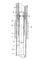
- FIG. 1 is an overall perspective view showing a state in which a steering device 101 according to an embodiment of the present invention is attached to a vehicle.
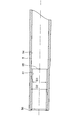
- FIG. 2 is a perspective view of a main part of the steering device 101 according to the embodiment of the present invention as viewed from the rear side of the vehicle body.
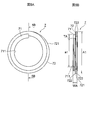
- FIG. 3 is a longitudinal sectional view showing a fitting state between the female steering shaft and the male steering shaft according to the embodiment of the present invention.
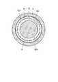
- 4 is a cross-sectional view taken along line 4-4 of FIG. 5A and 5B show the retaining member of FIG. 4,
- FIG. 5A is a front view of the retaining member, and
- FIG. 5B is a sectional view taken along the line 5B-5B of FIG. 5A.
- FIG. 6A and 6B show modified examples of the retaining member
- FIG. 6A is a front view of the retaining member
- FIG. 6B is a cross-sectional view taken along 6B-6B in FIG. 6A
- 7A is a front view showing the main part of the male steering shaft of FIG. 3
- FIG. 7B is a longitudinal sectional view showing the main part of the female steering shaft of FIG.
- FIG. 8 is a longitudinal sectional view showing a fitting state of the female steering shaft and the male steering shaft according to the second embodiment of the present invention.
- FIG. 9 is a longitudinal sectional view showing a main part of the female steering shaft of FIG.
- FIG. 10A is a front view showing a main part of the male steering shaft in a state in which the retaining member according to the first embodiment is assembled
- FIG. 10B is an enlarged view of the vicinity of the retaining member of FIG. 10C shows a state in which the steering shaft and the female steering shaft are being assembled
- FIG. 10C is an enlarged view of the vicinity of the retaining member of FIG. 10A and shows a deformed state of the retaining member
- FIG. It is a front view which shows the state with which the female steering shaft was assembled
- FIG. 11A is a front view showing the main part of the male steering shaft in a state where the retaining member according to the modification of the first embodiment is assembled
- FIG. 11B is an enlarged view of the vicinity of the retaining member of FIG. 11A.
- 11C shows a state in which the male steering shaft and the female steering shaft are being assembled,
- FIG. 11C is an enlarged view of the vicinity of the retaining member of FIG. 11A and shows a state in which the retaining member is deformed, and
- FIG. It is a front view which shows the state with which the steering shaft and the female steering shaft were assembled
- the direction related to the steering device is the same as the front / rear, left / right, and up / down directions of the vehicle body attached to the vehicle body unless otherwise specified.
- the left-right direction is also called the vehicle width direction.
- the paper when the code in the figure can be read in a normal direction, the paper is viewed from the lower left side of the page to the front side of the vehicle, the upper right side of the page is the rear side of the vehicle, and the upper left side of the page is On the right side in the vehicle width direction, the diagonally downward direction on the paper is the left side in the vehicle width direction.
- the paper when the code in the figure is read in a normal direction, the paper is viewed from the upper left side of the page, the lower right side of the page is the lower right side of the page, and the upper right side of the page is the upper right side of the page.
- the diagonally lower left direction on the right side in the vehicle width direction is the left side in the vehicle width direction.
- the paper surface is viewed in a state where the reference numerals in the figure can be read in the normal direction
- the back direction of the paper surface is the front side of the vehicle body
- the front side of the paper surface is the rear side of the vehicle body
- the right side of the paper surface is the right side of the vehicle width direction
- the left direction is the left side in the vehicle width direction.
- the front of the paper is the front side of the vehicle
- the back direction of the paper is the rear side of the vehicle
- the left side of the paper is the right side in the vehicle width direction.
- the right direction on the page is the left side in the vehicle width direction.
- FIG. 1 is an overall perspective view showing a state in which a steering device 101 according to a first embodiment of the present invention is attached to a vehicle.
- a steering shaft 102 is rotatably supported on the steering device 101.
- a steering wheel 103 is attached to the steering shaft 102 at the upper end on the rear side of the vehicle body, and an intermediate shaft 105 is connected to the lower end of the steering shaft 102 on the front side of the vehicle body via a universal joint 104.
- a universal joint 106 is connected to the lower end of the intermediate shaft 105, and a steering gear assembly 107 including a rack and pinion mechanism is connected to the universal joint 106.
- the rotational force is transmitted to the steering gear assembly 107 via the steering shaft 102, the universal joint 104, the intermediate shaft 105, and the universal joint 106, and via the rack and pinion mechanism,
- the tie rod 108 is moved to change the wheel turning angle.
- FIG. 2 is a perspective view of a main part of the steering device 101 according to the first embodiment of the present invention viewed from the rear side of the vehicle body.
- FIG. 3 is a longitudinal sectional view showing a fitting state of the female steering shaft and the male steering shaft according to the first embodiment of the present invention.
- 4 is a cross-sectional view taken along line 4-4 of FIG. 5A and 5B show the retaining member of FIG. 4
- FIG. 5A is a front view of the retaining member
- FIG. 5B is a sectional view taken along the line 5B-5B of FIG. 5A.
- 7A is a front view showing the main part of the male steering shaft of FIG. 3
- FIG. 7B is a longitudinal sectional view showing the main part of the female steering shaft of FIG.
- the steering apparatus 101 includes a vehicle body mounting bracket 2, an inner column 3 that is a lower column, a steering assist portion 31 that is an electric assist mechanism, and an outer column 4 that is an upper column. Etc.
- the right end of the steering assisting portion 31 that is an electric assist mechanism is fixed to the vehicle body front side portion of the inner column 3 by press-fitting.
- the steering assist unit 31 includes an electric motor 311, a reduction gear box unit 312, an output shaft 313, and the like.
- the steering assist unit 31 is supported so that the tilt position can be adjusted by attaching a bracket 314 formed integrally with the front end of the vehicle body of the steering assist unit 31 to a vehicle body (not shown) via a tilt center axis (not shown). ing. With such a configuration, the inner column 3 is supported by the vehicle body via the bracket 314 so that the tilt position can be adjusted.
- the outer peripheral surface 32 of the inner column 3 has an inner peripheral surface 41 of the outer column 4 that can be telescopically adjusted, that is, slidable parallel to the central axis of the inner column 3. It is fitted.
- a female steering shaft 5 is pivotally supported on the outer column 4 and a steering wheel 103 (see FIG. 1) is fixed to the rear end (right side in FIG. 3) of the female steering shaft 5 on the vehicle body. Yes.
- a slit (not shown) penetrating from the outer peripheral surface 42 of the outer column 4 to the inner peripheral surface 41 is formed in the lower portion of the outer column 4 on the vehicle body.
- a male steering shaft 6 is pivotally supported on the inner column 3 so that the male steering shaft 6 is spline-fitted with the female steering shaft 5. Accordingly, the rotation of the female steering shaft 5 is transmitted to the male steering shaft 6 regardless of the telescopic position of the outer column 4.
- the steering assist unit 31 detects the torque acting on the male steering shaft 6 and drives the electric motor 311 to rotate the output shaft 313 with a required steering assist force.
- the rotation of the output shaft 313 is transmitted to the steering gear assembly 107 via the universal joint 104, the intermediate shaft 105, and the universal joint 106, thereby changing the turning angle of the wheel.
- the vehicle body mounting bracket 2 is attached to the vehicle body so that it can move in a collapsible manner toward the front side of the vehicle body in the event of a secondary collision, and the vehicle body front side portion of the outer column 4 is sandwiched by the pair of side plates 22 and 22 from both the left and right sides in the vehicle width direction. .
- the collapse movement means that the secondary collision moves to the front side of the vehicle body while absorbing the energy of the secondary collision via an energy absorbing mechanism provided in the steering column, bracket or the like during the secondary collision.
- the adjustment of the tilt position and telescopic position of the steering wheel 103 is performed by rotating the operation lever 21.
- the operation lever 21 is rotated in a direction in which the pair of side plates 22 and 22 of the vehicle body mounting bracket 2 approach each other, the side plates 22 and 22 tighten the outer peripheral surface 42 of the outer column 4.
- the outer column 4 is clamped from the left and right directions by the side plates 22 and 22, and the steering wheel 103 is positioned at the tilt adjustment position.
- the inner peripheral surface 41 of the outer column 4 is reduced in diameter, and the outer peripheral surface 32 of the inner column 3 is tightened by the inner peripheral surface 41 of the outer column 4.
- the inner column 3 is clamped by the inner peripheral surface 41 of the outer column 4, and the steering wheel 103 is positioned at the telescopic adjustment position.
- the telescopic clamp and tilt clamp are released by rotating the operation lever 21 in the reverse direction.
- the operation lever 21 is rotated in the reverse direction to telescopic unclamp and tilt unclamp, and then the steering wheel 103 is adjusted in both the vertical position, that is, the tilt position and the front-rear direction position, that is, the telescopic position.
- the operation lever 21 is rotated in the direction in which the side plates 22 and 22 approach each other, and the steering wheel 103 is positioned at the tilt adjustment position and the telescopic adjustment position.
- the male steering shaft 6 and the female steering shaft 5 are configured such that a male spline 61 formed on the outer periphery of the vehicle rear side portion of the male steering shaft 6 is within the vehicle front side portion of the female steering shaft 5.
- a female spline 51 formed on the circumference is fitted into the spline 51 and engaged with the spline.
- the female spline 51 includes a female spline 511 on the front side of the vehicle body and a female spline 512 on the rear side of the vehicle body.
- a chamfer 56 is formed at the vehicle body front end of the female spline 511 on the vehicle body front side.
- the chamfer 56 may be either C chamfer or R chamfer.
- the outer peripheral surface of the male spline 61 of the male steering shaft 6 is in the vicinity of the rear end of the vehicle body, in other words, the outer peripheral surface in the vicinity of the end portion on the insertion side to the female steering shaft 5
- a groove 62 is formed.
- the groove bottom 621 of the outer peripheral annular groove 62 is formed on the inner diameter side with respect to the tooth bottom circle of the male spline 61.
- the retaining member 7 shown in FIGS. 5A and 5B is fitted into the outer peripheral annular groove 62 and assembled.
- the retaining member 7 is formed by forming a wire having a rectangular cross-section made of elastically deformable spring steel into a coil shape, and the entire shape is formed in a ring shape. More specifically, the first winding 71 and the second winding 72 having a larger diameter than the first winding 71 are formed into a conical coil spring having two windings, in other words, a two-conical spiral shape. Yes.
- chamfers 722 are formed on each ridge line portion of the wire.
- the chamfer 722 may be either a C chamfer or an R chamfer.
- each dimension of the retaining member 7 is defined as shown in FIG. 5B. That is, in the free state of the retaining member 7, the inner diameter dimension of the inner peripheral surface 711 of the first winding 71 is the ring inner diameter a1, and the outer diameter dimension of the outer peripheral surface 721 of the second winding 72 is the ring outer diameter A1.
- the dimension of the retaining member 7 in the assembled state in the longitudinal direction of the vehicle body is defined as the ring width WA, and the dimension of the wire constituting the retaining member 7 in the vertical direction of the vehicle body is defined as the ring thickness TA.
- the dimensions of predetermined portions of the male steering shaft 6 and the female steering shaft 5 are defined as shown in FIGS. 7A and 7B.
- the diameter dimension of the groove bottom 621 of the outer peripheral annular groove 62 is the outer peripheral annular groove bottom diameter d1
- the root diameter of the male spline 61 is the male spline small diameter d2
- the tooth tip diameter of the male spline 61 is Is the male spline large diameter d3
- the dimension of the outer peripheral annular groove 62 in the longitudinal direction of the vehicle body is the outer peripheral annular groove width W.
- the outer peripheral annular groove width W is formed to be larger than the ring width WA of the retaining member 7.
- the root diameter of the female spline 51 is the female spline large diameter D2, and the tip diameter of the female spline 51 is the female spline small diameter D3.
- the diameter of a later-described escape hole 54 in the rear side portion of the vehicle body is a female steering shaft inner diameter D1.
- the chamfer 56 of the female spline 51 is formed with a difference thickness between the female spline large diameter D2 and the female spline small diameter D3 when the female steering shaft 5 is viewed in the axial direction from the front side of the vehicle body.
- the chamfer 56 is formed so that the dimension in the direction orthogonal to the axial direction of the female steering shaft 5, that is, the radial thickness dimension is equal to the difference between the female spline large diameter D2 and the female spline small diameter D3.
- the ring inner diameter a1 is formed slightly smaller than the outer peripheral groove bottom diameter d1.
- the ring outer diameter A1 is smaller than the male spline large diameter d3 and larger than the male spline small diameter d2.
- the outer peripheral surface 71 of the retaining member 7 is located within the tooth height range of the male spline 61 when viewed from the axial direction.
- the ring outer diameter A1 is formed so as to be larger than the female spline small diameter D3 and smaller than the female spline large diameter D2 in a state where the retaining member 7 is assembled in the outer peripheral annular groove 62.
- the outer peripheral surface 721 of the second turn 72 of the retaining member 7 assembled in the outer peripheral annular groove 62 is within the thickness range of the chamfer 56 of the female steering shaft 5 arranged coaxially when viewed from the axial direction. Is located.
- an inner peripheral annular groove 52 is formed on the inner peripheral surface of the female steering shaft 5 in the vicinity of the front end of the vehicle body, that is, in the vicinity of the end portion on the insertion side of the male steering shaft 6. Yes.
- the inner annular groove 52 is a portion where the female spline 51 is not provided.
- the female spline 51 includes a female spline 511 on the front side of the vehicle body and a female spline 512 on the rear side of the vehicle body, and an inner circumferential annular groove is formed between the female spline 511 on the front side of the vehicle body and the female spline 512 on the rear side of the vehicle body. 52.
- the female spline 511 on the front side of the vehicle body and the female spline 512 on the rear side of the vehicle body have the same phase.
- the rear end of the female spline 511 on the front side of the vehicle body is a vertical surface that is formed perpendicular to the axis of the female steering shaft 5.
- the front end of the female spline 512 on the rear side of the vehicle body is an inclined surface 522 that is inclined in a direction in which the rear side of the vehicle body approaches the axis.
- the rear end of the female spline 512 on the rear side of the vehicle body is an inclined surface 53 that is inclined in a direction in which the front side of the vehicle body approaches the axis.
- the diameter of the groove bottom of the inner peripheral annular groove 52 is the same as the female spline large diameter D2.
- the front end of the inner circumferential annular groove 52 in the vehicle body in other words, the insertion side of the male steering shaft 6 is a shoulder 521 formed of a vertical surface of the rear end of the female spline 511 on the front side of the vehicle body.
- the rear end of the inner circumferential annular groove 52 in the vehicle body in other words, the opposite side of the male steering shaft 6 is an inclined surface 522 at the front end of the female spline 512 on the rear side of the vehicle body.
- the female steering shaft 5 has a clearance hole larger in diameter than the female spline large diameter D2 in the inner peripheral surface of the rear portion of the vehicle body rather than the female spline 512 on the rear side of the vehicle body. 54 is formed. Since the axial length of the escape hole 54 is slightly longer than the telescopic movement distance between the outer column 4 and the inner column 3, the retaining member 7 is disposed within the escape hole 54 with the male steering shaft 6. At the same time, telescopic movement is possible.
- the diameter of the escape hole 54 that is, the female steering shaft inner diameter D 1 is formed to be larger than the ring outer diameter A 1 of the retaining member 7, there is a gap between the escape hole 54 and the retaining member 7. It is formed. For this reason, there is no contact between the escape hole 54 and the retaining member 7 during telescopic movement. As a result, the retaining member 7 does not become a sliding resistance during telescopic movement, and no abnormal noise is generated due to sliding.
- FIG. 10A is a front view showing a main part of the male steering shaft 6 in a state where the retaining member 7 according to the first embodiment is assembled
- FIG. 10B is an enlarged view of the vicinity of the retaining member 7 in FIG. 10A
- 10C shows a state in which the male steering shaft 6 and the female steering shaft 5 are being assembled
- FIG. 10C is an enlarged view of the vicinity of the retaining member 7 in FIG. 10A and shows a state in which the retaining member 7 is deformed
- FIG. 10D is a front view showing a state in which the male steering shaft 6 and the female steering shaft 5 are assembled.
- the outer peripheral surface of the first winding 71 is positioned on the inner diameter side of the tooth bottom of the male spline 61, and the second winding
- the outer peripheral surface 721 of 72 is located on the outer diameter side of the tooth bottom of the male spline 61 and on the inner diameter side of the tooth tip.
- the retaining member 7 has a first roll 71 disposed on the rear side of the vehicle body and a second roll 72 disposed on the front side of the vehicle body.
- a chamfer 56 is formed at the vehicle body front end of the female spline 51, and a chamfer 722 is also formed at the outer diameter side portion of the second winding 72 of the retaining member 7. For this reason, when the male spline 61 and the female spline 51 are further fitted, the chamfer 56 and the chamfer 722 slide relative to each other. Then, as shown in FIG. 10C, the second winding 72 is elastically deformed and contracted by smoothly moving relative to the tooth tip portion from the chamfered portion 56 of the female spline 51. At the same time, the entire retaining member 7 is elastically deformed and extends in the longitudinal direction of the vehicle body.
- the retaining member 7 is located at the front end of the outer circumferential annular groove 62 and cannot extend to the front side of the vehicle body, and therefore extends to the rear side of the vehicle body.
- the first roll 71 moves to the rear side of the vehicle body as shown in FIG. 10C.
- the outer peripheral annular groove width W is sufficiently larger than the ring width WA (see FIG. 5B) of the retaining member 7 so that the retaining member 7 can extend in the longitudinal direction of the vehicle body. It is formed with dimensions.
- the male spline 61 and the female spline 51 are further fitted, and the male steering shaft 6 and the female steering shaft 5 are assembled as shown in FIG. 10D.
- the second winding 72 of the retaining member 7 is elastically restored to expand its diameter, and at the same time, the retaining member. 7 is restored elastically and contracts in the longitudinal direction of the vehicle body.
- the ring outer diameter A1 (see FIG. 5B) of the retaining member 7 becomes the same state as shown in FIG. 10A.
- the male steering shaft 6 can be telescopically moved by spline fitting to the female steering shaft 5, and the retaining member 7 can be telescopically moved together with the male steering shaft 6 in the escape hole 54.
- the retaining member 7 Since the inner peripheral surface 711 of the retaining member 7 fastens the groove bottom 621 of the outer peripheral annular groove 62 of the male steering shaft 6 as described above, the retaining member 7 is attached to the outer peripheral annular groove 62 without backlash. No abnormal noise is generated during operation.
- the outer column 4 When adjusting the telescopic position from the state where the retaining member 7 is located within the range of the escape hole 54 in the normal state after the steering device is assembled to the vehicle body, the outer column 4 is pulled to the rear side of the vehicle body.
- the outer peripheral surface 721 of the retaining member 7 contacts the inclined surface 53 of the rear end of the female spline 512 on the rear side of the vehicle body by telescopic movement, the outer peripheral surface 721 of the second winding 72 of the retaining member 7 is chamfered 722. Further, the second winding 72 is guided by the inclined surface 53, so that the retaining member 7 is smoothly reduced in diameter.
- the adjustment range of the telescopic position of the steering wheel 103 (see FIG. 1) in the normal state after being assembled to the vehicle body is such that the retaining member 7 is located at the front end of the female spline 512 on the vehicle body rear side from the predetermined position of the escape hole 54. It is set to the range until moving to a nearby position. In other words, the retaining member 7 escapes when the length of the fitting portion between the male spline 61 of the male steering shaft 6 and the female spline 51 of the female steering shaft 5 is the longest, that is, when the steering shaft is the shortest. It is located at a predetermined position of the hole 54.
- the retaining member 7 is the front end of the female spline 512 on the vehicle body rear side. Located in the vicinity.
- the inner circumferential annular groove 52 is located at a position deviating from the moving range of the retaining member 7 relative to the female spline shaft 5 corresponding to the telescopic position adjustment range of the steering wheel 103 to the side where the telescopic adjustment position becomes longer. Is formed. That is, the retaining member 7 is not positioned in the inner peripheral annular groove 52 in the normal telescopic position adjustment range. In other words, the retaining member 7 has an inner periphery when the length of the portion where the male steering shaft 6 and the female steering shaft 5 are fitted is shorter than the shortest of the normal adjustment range. It will be located in the annular groove 52.
- the steering device 101 having such a structure of the steering shaft is attached to the vehicle body, specifically, in a state before the vehicle body mounting bracket 2 is attached to the vehicle body, for example, during transportation or when a column cover (not shown) is assembled.
- the lever 21 may be operated by mistake to release the telescopic clamp and the tilt clamp of the inner column 3 with respect to the outer column 4.
- the retaining member 7 enters the inner circumferential annular groove 52 near the front end of the female spline 51 in the vehicle body. Expand the diameter.
- the second winding 72 of the retaining member 7 comes into contact with the shoulder portion 521 at the front end of the inner circumferential annular groove 52 in the vehicle body.
- the contact portion of the second winding 72 that contacts the shoulder portion 521 is an end surface of the second winding 72 on the vehicle body front side. Since the shoulder 521 is a vertical surface in which the rear end of the female spline 511 on the front side of the vehicle body is formed perpendicular to the axis of the female steering shaft 5, the second turn 72 of the retaining member 7 is the shoulder 521.
- the diameter cannot be reduced even when abutting against. For this reason, the male steering shaft 6 cannot move further in the direction of coming out of the female steering shaft 5. As a result, it is possible to reliably prevent the male steering shaft 6 from coming out of the female steering shaft 5. That is, it is possible to reliably prevent the inner column 3 from coming out of the outer column 4.
- the male spline 61 on the front side of the vehicle body with respect to the outer peripheral annular groove 62 is fitted with the female spline 511 on the front side of the vehicle body. Further, the male spline 61 on the rear side of the vehicle body with respect to the outer peripheral annular groove 62 is fitted with the female spline 512 on the rear side of the vehicle body.
- the phase of the male spline 61 and the phase of the female spline 51 are maintained.
- the second winding 72 which is the large diameter portion of the retaining member 7, prevents the male steering shaft 6 from slipping out of the female steering shaft 5 by contacting the shoulder 521. That is, in the retaining member 7, the second winding 72 having a large diameter constitutes a retaining portion for preventing the male steering shaft 6 from coming off from the female steering shaft 5, and the entire structure including the first winding 71 is the male steering shaft.
- An elastically deformable portion that is elastically deformed when the 6 and the female steering shaft 5 are assembled is configured.
- the outer circumferential surface 721 of the retaining member 7 is inner circumferentially annular.
- the diameter of the groove 52 is reduced smoothly by being guided by the inclined surface 522 at the rear end of the vehicle body. Accordingly, it is possible to continue the telescopic movement by pushing the outer column 4 further forward of the vehicle body while bringing the outer peripheral surface 721 of the retaining member 7 into contact with the tooth tip of the female spline 512 on the vehicle body rear side. In this way, the male steering shaft 6 can be prevented from slipping out of the female steering shaft 5, and the female steering shaft 5 and the male steering shaft 6 can be returned to their original states by normal telescopic movement.
- the escape prevention structure is an internal structure of the outer column 4 and the inner column 3, it has little influence on the external shape of the steering device and the vehicle body side, and can be applied to many types of steering devices.
- the retaining member 7 may be constituted by a wire. Since the wire has a circular cross section, it is not necessary to chamfer, and the number of processes and the manufacturing cost can be reduced.
- FIG. 6A and 6B show modified examples of the retaining member
- FIG. 6A is a front view of a modified example of the retaining member
- FIG. 6B is a cross-sectional view taken along 6B-6B in FIG. 6A.
- the retaining member 8 of the modified example is formed by forming a wire having a rectangular cross section made of elastically deformable spring steel into a substantially ring-shaped C shape with a part of a circular shape cut out.
- One of the seven protrusions 82 is opposed to the notch of the C-shaped portion 80, and the remaining protrusions 82 are paired with each other centering on the axis of the C-shaped portion 80. Three pairs are formed.
- Each protrusion 82 is formed by being bent by a predetermined angle ⁇ in the same direction so as to rise from the inner peripheral surface 81 when viewed from the direction orthogonal to the axial center.
- each dimension of the retaining member 8 is defined as shown in FIGS. 6A and 6B. That is, the outer diameter of the outer peripheral surface 83 of the C-shaped portion 80 is the ring outer diameter B1, and the distance between the tips of the opposing projections 82 and 82 is the ring inner diameter b1. Further, the dimension in the vehicle longitudinal direction in the state in which the retaining member 8 is assembled is the ring width WB, and the dimension in the vehicle vertical direction of the wire constituting the C-shaped portion 80 is the ring thickness TB.
- the outer peripheral annular groove width W (see FIG. 7A) is formed to be larger than the ring width WB.
- the protruding end of the protrusion 82 is formed so as to protrude from the groove bottom 621 of the outer peripheral annular groove 62 to the inner diameter side.
- the ring outer diameter B1 is smaller than the male spline large diameter d3 and larger than the male spline small diameter d2. Dimension is formed.
- the outer peripheral surface 83 of the retaining member 8 is located within the tooth height range of the male spline 61 when viewed from the axial direction.
- the ring outer diameter B1 is formed so as to be larger than the female spline small diameter D3 and smaller than the female spline large diameter D2 in a state where the retaining member 8 is assembled to the outer peripheral annular groove 62. Yes.
- the outer peripheral surface 83 of the retaining member 8 assembled in the outer peripheral annular groove 62 is positioned within the radial thickness range of the chamfer 56 of the female steering shaft 5 arranged coaxially when viewed from the axial direction. is doing. Since the protrusion 82 is bent by an angle ⁇ , the protrusion 82 is easily elastically deformed, and the C-shaped portion 80 of the retaining member 8 can be smoothly expanded and contracted.
- FIG. 11A is a front view showing a main part of the male steering shaft 6 in a state in which the retaining member 8 according to a modification of the first embodiment is assembled
- FIG. 11B is a view of the vicinity of the retaining member 8 of FIG. 11A
- FIG. 11C is an enlarged view showing a state where the male steering shaft 6 and the female steering shaft 5 are being assembled
- FIG. 11C is an enlarged view of the vicinity of the retaining member 8 of FIG.
- FIG. 11D is a front view showing a state in which the male steering shaft 6 and the female steering shaft 5 are assembled.
- the outer circumferential surface 83 is located on the inner diameter side of the tooth tip of the male spline 61.
- the retaining member 8 is arranged so that the front end side of each protrusion 82 is the rear side of the vehicle body and the C-shaped portion 80 is the front side of the vehicle body. By disposing the retaining member 8 in this direction, the assembling property between the male steering shaft 6 and the female steering shaft 5 is improved.
- the retaining member 8 is formed such that the protruding end of the projection 82 projects to the inner diameter side of the groove bottom 621 of the outer peripheral annular groove 62, so the ring inner diameter b1 (see FIG.
- the retaining member 8 is It is formed slightly smaller in diameter than the outer peripheral annular groove bottom diameter d1 (see FIG. 7A). For this reason, the retaining member 8 is attached without backlash, with each projection 82 tightening the outer peripheral annular groove 62.
- a chamfer 56 is formed at the front end of the female spline 51 in the vehicle body, and a chamfer 831 is also formed on the outer peripheral surface 83 of the C-shaped portion 80. Therefore, when the male spline 61 and the female spline 51 are further fitted. The chamfer 56 and the chamfer 831 slide relative to each other. Then, as shown in FIG. 11C, the C-shaped portion 80 smoothly moves relative to the tooth tip side from the chamfered portion 56 of the female spline 51, thereby reducing the interval between the notch portions and reducing the diameter. At the same time, each protrusion 82 is elastically deformed so as to fall in a direction parallel to the groove bottom 621 of the outer peripheral annular groove 62.
- the outer peripheral annular groove width W (see FIG. 7A) is set so that the C-shaped portion 80 of the retaining member 8 can move in the longitudinal direction of the vehicle body, so that the ring width WB of the retaining member 8 (see FIG. 6B). It is formed with a dimension sufficiently larger than that.
- the male spline 61 and the female spline 51 are further fitted, and the male steering shaft 6 and the female steering shaft 5 are assembled as shown in FIG. 11D.
- the retaining member 8 may be deformed and elastically deformed after being pushed by the female spline 51 and moved entirely to the front end of the outer circumferential annular groove 62 in the vehicle body.
- the male steering shaft 6 can be telescopically moved by spline fitting to the female steering shaft 5, and the retaining member 7 can be telescopically moved together with the male steering shaft 6 in the escape hole 54.
- the protruding end of the protrusion 82 of the retaining member 8 is attached to the outer peripheral annular groove 62 without looseness in order to tighten the groove bottom 621 of the outer peripheral annular groove 62 of the male steering shaft 6, and abnormal noise is generated during the driving operation. It does not occur.
- the angle ⁇ of the protrusion 82 can be formed at an angle at which the male steering shaft 6 and the female steering shaft 5 can be easily assembled depending on the type of the steering device. Other effects are the same as those of the first embodiment.
- the C-shaped portion 80 of the retaining member 8 When the male steering shaft 6 moves relatively away from the female steering shaft 5, the C-shaped portion 80 of the retaining member 8 enters the inner peripheral annular groove 52 of the female spline 51 and elastically returns to expand the diameter. Then, the C-shaped portion 80 of the retaining member 8 comes into contact with the shoulder portion 521 at the front end of the inner circumferential annular groove 52 in the vehicle body. At this time, the contact portion of the C-shaped portion 80 that contacts the shoulder portion 521 is the end surface of the C-shaped portion 80 on the vehicle body front side.
- the shoulder portion 521 is a vertical surface in which the rear end of the female spline 511 on the front side of the vehicle body is formed perpendicular to the axis of the female steering shaft 5, the C-shaped portion 80 of the retaining member 7 is the shoulder portion 521.
- the diameter cannot be reduced even when abutting against. For this reason, the male steering shaft 6 cannot move further in the direction of coming out of the female steering shaft 5. As a result, it is possible to reliably prevent the male steering shaft 6 from coming out of the female steering shaft 5. That is, it is possible to reliably prevent the inner column 3 from coming out of the outer column 4.
- the male spline 61 on the front side of the vehicle body with respect to the outer peripheral annular groove 62 is fitted with the female spline 511 on the front side of the vehicle body. Further, the male spline 61 on the rear side of the vehicle body with respect to the outer peripheral annular groove 62 is fitted with the female spline 512 on the rear side of the vehicle body.
- the phase of the male spline 61 and the phase of the female spline 51 are maintained.
- the C-shaped portion 80 of the retaining member 8 is in contact with the shoulder portion 521 to prevent the male steering shaft 6 from slipping out of the female steering shaft 5. That is, in the retaining member 8, the substantially ring-shaped C-shaped portion 80, which is a large-diameter portion, constitutes a retaining portion that prevents the male steering shaft 6 from coming off from the female steering shaft 5.
- Each protrusion 82 formed on the inner diameter side constitutes an elastic deformation portion that elastically deforms when the male steering shaft 6 and the female steering shaft 5 are assembled.
- FIG. 8 is a longitudinal sectional view showing a fitting state between the female steering shaft and the male steering shaft according to the second embodiment of the present invention.
- FIG. 9 is a longitudinal sectional view showing a main part of the female steering shaft of FIG.
- the second embodiment is a modification of the first embodiment, in which the shape of the female steering shaft 5 is changed.
- the male steering shaft 6 and the retaining member 7 are the same as those in the first embodiment, detailed description of the male steering shaft 6 and the retaining member 7 is omitted. That is, the coil-shaped retaining member 7 is assembled in the outer peripheral annular groove 62 in the vicinity of the rear end of the vehicle body of the male spline 61. Further, in the second embodiment, as shown in FIG. 9, the first inner surface of the female spline 51 of the female steering shaft 5, in the vicinity of the vehicle body front end, that is, the inner peripheral surface of the male steering shaft 6 in the vicinity of the insertion side end, Unlike the embodiment, the inner peripheral annular groove 52 is not formed.
- the female steering shaft 5 has a clearance diameter 54 larger than the diameter of the bottom of the female spline 51, that is, the female spline large diameter D2, on the inner peripheral surface of the rear side of the vehicle body from the female spline 51. Since the axial length of the escape hole 54 is slightly longer than the telescopic movement distance between the outer column 4 and the inner column 3, the retaining member 7 is disposed within the escape hole 54 with the male steering shaft 6. At the same time, telescopic movement is possible.
- a shoulder portion 55 that connects the female spline 51 and the escape hole 54 is formed at the rear end of the female spline 51 in the vehicle body, that is, the opposite end of the male steering shaft 6.
- the shoulder 55 is a vertical surface in which the rear end of the female spline 51 is formed perpendicular to the axis of the female steering shaft 5.
- the retaining member 7 is wound twice. Since the outer peripheral surface 721 of the eye 72 comes into contact with the chamfer 56 and the tooth tip of the female spline 51 and is elastically deformed to reduce the diameter, the male steering shaft 6 can be inserted into the female steering shaft 5.
- the outer peripheral surface 721 of the second winding 72 of the retaining member 7 is elastically restored and expanded in diameter
- the outer diameter of the outer peripheral surface 721 of the retaining plate member 7, that is, the ring A outer diameter A1 (see FIG. 5B) is the same as the state shown in FIG. 10A.
- the male steering shaft 6 can be telescopically moved by spline fitting to the female steering shaft 5, and the retaining member 7 can be telescopically moved together with the male steering shaft 6 in the escape hole 54.
- the operation lever 21 may be operated by mistake, and the telescopic clamp and the tilt clamp of the inner column 3 may be released with respect to the outer column 4.
- the retaining member 7 comes into contact with the rear end of the female spline 51, that is, the shoulder 55 on the opposite side of the male spline 6. Since the shoulder 55 is a vertical surface in which the rear end of the female spline 51 is perpendicular to the axis of the female steering shaft 5, the second winding 72 of the retaining member 7 is in contact with the shoulder 55. After that, the diameter is not reduced.
- the male steering shaft 6 cannot move further in the direction of coming out of the female steering shaft 5.
- the shoulder 55 is formed outside the range of movement of the retaining member 7 relative to the female spline shaft 5 corresponding to the telescopic position adjustment range of the steering wheel 103. That is, the retaining member 7 does not come into contact with the shoulder portion 55 in the normal telescopic position adjustment range after mounting the vehicle body.
- Other configurations and effects are the same as those of the first embodiment. In addition, even if it uses the retaining member 8 instead of the retaining member 7 in 2nd Embodiment, the effect is the same.
- the present invention is not limited to the spline shaft, and the rotational torque of the serration shaft or the like is used. Any non-circular shaft can be used.
- the example in which the female steering shaft 5 is pivotally supported by the outer column 4 and the male steering shaft 6 is pivotally supported by the inner column 3 has been described.
- the present invention may be applied to a steering apparatus in which the steering shaft 5 is pivotally supported and the male steering shaft 6 is pivotally supported on the outer column 4.
- the present invention is applied to a tilt / telescopic steering device capable of both tilt position adjustment and telescopic position adjustment.
- telescopic steering capable of only telescopic position adjustment is described.
- the present invention may be applied to an apparatus.
- the retaining member 7 and the retaining member 8 may be plated. Plating has the effect of lowering the coefficient of friction, and can be processed at low cost for steel. Further, the retaining member 7 and the retaining member 8 may be coated with a bottom friction agent, or grease may be applied. These both have the effect of reducing the friction coefficient of the retaining member 7 and the retaining member 8, and by sliding between the retaining member 7 and the retaining member 8 and the female spline 51 as in the case of plating. Abnormal noise can be prevented.
Abstract
Description
まず、本明細書中におけるステアリング装置に係る方向について定義する。本明細書中においては、ステアリング装置に係る方向は、特に明記しない限り車体に取り付けられた状態における当該車体の前後、左右、上下方向と同様とする。左右方向については車幅方向ともいう。図1においては、図中の符号を通常の向きに読める状態で紙面を見て、紙面左斜め下方向が車体前方側で紙面右斜め上方向が車体後方側であり、紙面左斜め上方向が車幅方向右側で紙面右斜め下方向が車幅方向左側である。図2においては、図中の符号を通常の向きに読める状態で紙面を見て、紙面左斜め上方向が車体前方側で紙面右斜め下方向が車体後方側であり、紙面右斜め上方向が車幅方向右側で紙面左斜め下方向が車幅方向左側である。図3、5B、6B、7A、7B、8、9、10A~10D、11A~11Dにおいては、図中の符号を通常の向きに読める状態で紙面を見て、紙面左方向が車体前方側で紙面右方向が車体後方側であり、紙面奥方向が車幅方向右側で紙面手前方向が車幅方向左側である。図4においては、図中の符号を通常の向きに読める状態で紙面を見て、紙面奥方向が車体前方側で紙面手前方向が車体後方側であり、紙面右方向が車幅方向右側で紙面左方向が車幅方向左側である。図5A、6Aにおいては、図中の符号を通常の向きに読める状態で紙面を見て、紙面手前方向が車体前方側で紙面奥方向が車体後方側であり、紙面左方向が車幅方向右側で紙面右方向が車幅方向左側である。 Hereinafter, a first embodiment and a second embodiment of the present invention will be described based on the drawings.
First, directions related to the steering device in this specification will be defined. In the present specification, the direction related to the steering device is the same as the front / rear, left / right, and up / down directions of the vehicle body attached to the vehicle body unless otherwise specified. The left-right direction is also called the vehicle width direction. In FIG. 1, when the code in the figure can be read in a normal direction, the paper is viewed from the lower left side of the page to the front side of the vehicle, the upper right side of the page is the rear side of the vehicle, and the upper left side of the page is On the right side in the vehicle width direction, the diagonally downward direction on the paper is the left side in the vehicle width direction. In FIG. 2, when the code in the figure is read in a normal direction, the paper is viewed from the upper left side of the page, the lower right side of the page is the lower right side of the page, and the upper right side of the page is the upper right side of the page. The diagonally lower left direction on the right side in the vehicle width direction is the left side in the vehicle width direction. 3, 5B, 6B, 7A, 7B, 8, 9, 10A to 10D, and 11A to 11D, the sign in the figure can be read in the normal direction, and the left side is the front side of the vehicle body. The right side of the page is the rear side of the vehicle body, the rear side of the page is the right side in the vehicle width direction, and the front side of the page is the left side in the vehicle width direction. In FIG. 4, the paper surface is viewed in a state where the reference numerals in the figure can be read in the normal direction, the back direction of the paper surface is the front side of the vehicle body, the front side of the paper surface is the rear side of the vehicle body, and the right side of the paper surface is the right side of the vehicle width direction The left direction is the left side in the vehicle width direction. In FIGS. 5A and 6A, the front of the paper is the front side of the vehicle, the back direction of the paper is the rear side of the vehicle, and the left side of the paper is the right side in the vehicle width direction. The right direction on the page is the left side in the vehicle width direction.
図1は本発明の第1実施形態のステアリング装置101を車両に取り付けた状態を示す全体斜視図である。ステアリング装置101には、ステアリングシャフト102が回動自在に軸支されている。ステアリングシャフト102には、その車体後方側の上端にステアリングホイール103が装着され、ステアリングシャフト102の車体前方側の下端には、ユニバーサルジョイント104を介して中間シャフト105が連結されている。 (First embodiment)
FIG. 1 is an overall perspective view showing a state in which a
次に、第1実施形態の変形例について説明する。変形例は第1実施形態とは抜け止め部材の形態が異なっており、他の構成は同様である。そのため、以下の説明では、第1実施形態と異なる構成を中心に説明し、重複する説明は省略する場合もある。また、同一部品には同一番号を付し、第1実施形態で用いた図を流用して説明する。 (Modification)
Next, a modification of the first embodiment will be described. The modified example is different from the first embodiment in the form of the retaining member, and the other configurations are the same. Therefore, in the following description, it demonstrates centering around a different structure from 1st Embodiment, and the overlapping description may be abbreviate | omitted. The same parts are denoted by the same reference numerals, and the drawings used in the first embodiment are used for explanation.
次に第2実施形態について説明する。 (Second Embodiment)
Next, a second embodiment will be described.
Claims (10)
- インナーコラムと、
上記インナーコラムに軸方向に相対移動可能に嵌合されたアウターコラムと、
上記アウターコラムの上記インナーコラムに対する相対位置を固定するためのクランプ機構と、
上記インナーコラムまたはアウターコラムのいずれか一方に回動可能に軸支され、内周面に雌スプラインが設けられた雌ステアリングシャフトと、
上記インナーコラムまたはアウターコラムのいずれか他方に回動可能に軸支され、外周面に雄スプラインが設けられ、該雄スプラインは上記雌スプラインに挿入されることより該雌スプラインと嵌合し、上記雌ステアリングシャフトに対し軸方向に移動可能にかつトルク伝達可能な雄ステアリングシャフトとを備え、雌ステアリングシャフトまたは雄ステアリングシャフトに取付けられたステアリングホイールのテレスコピック位置を調整可能なステアリング装置において、
上記雌ステアリングシャフトおよび上記雄ステアリングシャフトには、上記雌スプラインと上記雄スプラインとの嵌合部分を残した状態で該雌ステアリングシャフトと該雄ステアリングシャフトとの軸方向の抜けを防止するための抜け止め機構が設けられていることを特徴とするステアリング装置。 An inner column,
An outer column fitted to the inner column so as to be relatively movable in the axial direction;
A clamp mechanism for fixing the relative position of the outer column to the inner column;
A female steering shaft pivotally supported on one of the inner column and the outer column and having a female spline on the inner peripheral surface;
The inner column or the outer column is pivotally supported by the other, a male spline is provided on the outer peripheral surface, and the male spline is fitted into the female spline by being inserted into the female spline. A steering device that includes a male steering shaft that is axially movable and capable of transmitting torque to a female steering shaft, and is capable of adjusting the telescopic position of a steering wheel attached to the female steering shaft or the male steering shaft.
In the female steering shaft and the male steering shaft, the female steering shaft and the male steering shaft are removed to prevent the female steering shaft and the male steering shaft from coming off in the axial direction with the fitting portion between the female spline and the male spline remaining. A steering device characterized in that a stop mechanism is provided. - 上記抜け止め機構は、上記雄スプラインに周方向に形成された外周側環状溝と、上記外周側環状溝に嵌め込まれた弾性変形可能なリング状部材と、上記雌スプラインの軸方向の一部分または上記雄スプラインが挿入される側とは反対側の端部に隣接して設けられた拡径部とから構成され、
上記拡径部は、上記雌スプラインの歯先円よりも大径でかつ上記リング状部材の幅寸法よりも大きい幅寸法に形成され、上記雌ステアリングシャフトと上記雄ステアリングシャフトとの相対位置が上記拡径部と上記外周側環状溝とが径方向に重なる位置となる状態において上記雌スプラインと上記雄スプラインとの嵌合部分が残っている位置に設けられており、
上記リング状部材は、上記雄スプラインが上記雌スプラインに挿入される際上記雌スプラインに当接することで弾性変形して縮径し、上記雌スプラインに対する上記雄スプラインの軸方向の移動を可能にするとともに、上記雌スプラインと上記雄スプラインとの嵌合後であって上記ステアリング装置を車体に取付ける前の状態において、上記雌ステアリングシャフトと上記雄ステアリングシャフトとが軸方向で抜ける方向へ相対移動した際、上記拡径部で上記縮径状態から弾性復帰して拡径し、上記雌スプラインに当接することで上記雌ステアリングシャフトと前記雄ステアリングシャフトとの軸方向の抜けを防止することを特徴とする請求項1に記載のステアリング装置。 The retaining mechanism includes an outer circumferential annular groove formed in the male spline in the circumferential direction, an elastically deformable ring member fitted in the outer circumferential annular groove, and a part of the female spline in the axial direction or the It is composed of an enlarged diameter portion provided adjacent to the end opposite to the side on which the male spline is inserted,
The enlarged diameter portion is formed to have a larger diameter than the tip of the female spline and larger than the width of the ring-shaped member, and the relative position between the female steering shaft and the male steering shaft is In the state where the enlarged diameter portion and the outer peripheral annular groove are in a position overlapping in the radial direction, the fitting portion between the female spline and the male spline is provided at a position where it remains.
When the male spline is inserted into the female spline, the ring-shaped member is elastically deformed and contracted in diameter by being brought into contact with the female spline, thereby enabling the male spline to move in the axial direction with respect to the female spline. In addition, after the female spline and the male spline are fitted and before the steering device is attached to the vehicle body, the female steering shaft and the male steering shaft are moved relative to each other in the axial direction. The diameter-expanded portion elastically recovers from the reduced diameter state and expands the diameter, and comes into contact with the female spline to prevent the female steering shaft and the male steering shaft from coming off in the axial direction. The steering apparatus according to claim 1. - 上記雄スプラインが挿入される側の上記雌スプラインの端部には面取り部が設けられ、上記雌ステアリングシャフトの内周面部分であって上記雄スプラインが挿入される側とは反対側の部分には、上記雌スプラインの歯底円よりも大径の大径部が形成されており、
上記雄スプラインの外周側環状溝は底面が上記雄スプラインの歯底円よりも内径側に形成されており、
上記リング状部材は、外径側に面取り部が設けられ、外径寸法が上記雄スプラインの歯先面の径よりも小さくかつ上記雄スプラインの歯底円の径よりも大きく形成され、上記雄ステアリングシャフトの軸方向から見て、外周面が該雄ステアリングシャフトと同軸に配置した上記雌ステアリングシャフトの上記雌スプラインに設けられた上記面取り部の径方向の厚さの範囲内に位置しており、
上記雄スプラインが上記雌スプラインに挿入される際上記リング状部材は、外径側の上記面取り部が上記雌スプラインの面取り部と摺動することで弾性変形して縮径しかつ上記外径側環状溝内を軸方向に移動可能であり、
上記リング状部材が上記雌ステアリングシャフトの上記大径部に位置しているときは、上記リング状部材の上記外周面と上記大径部の内周面との間には、隙間が介在していることを特徴とする請求項2に記載のステアリング装置。 A chamfered portion is provided at the end of the female spline on the side where the male spline is inserted, and an inner peripheral surface portion of the female steering shaft on a portion opposite to the side where the male spline is inserted. Is formed with a larger diameter portion than the root circle of the female spline,
The outer circumferential annular groove of the male spline is formed on the inner diameter side of the bottom circle of the male spline,
The ring-shaped member is provided with a chamfered portion on the outer diameter side, the outer diameter dimension is smaller than the diameter of the tooth tip surface of the male spline and larger than the diameter of the root circle of the male spline. When viewed from the axial direction of the steering shaft, the outer peripheral surface is located within the radial thickness range of the chamfered portion provided in the female spline of the female steering shaft arranged coaxially with the male steering shaft. ,
When the male spline is inserted into the female spline, the ring-shaped member is elastically deformed and contracted by sliding the chamfered portion on the outer diameter side with the chamfered portion of the female spline, and the outer diameter side. It can move in the axial direction in the annular groove,
When the ring-shaped member is located at the large-diameter portion of the female steering shaft, a gap is interposed between the outer peripheral surface of the ring-shaped member and the inner peripheral surface of the large-diameter portion. The steering apparatus according to claim 2, wherein - 上記雌ステアリングシャフトと上記雄ステアリングシャフトとが軸方向で抜ける方向へ相対移動した際、上記拡径部において上記リング状部材が当接する上記雌スプラインの当接部は、上記雌ステアリングシャフトの軸心に対して垂直な面に形成されていることを特徴とする請求項2または3に記載のステアリング装置。 When the female steering shaft and the male steering shaft move relative to each other in the axial direction, the contact portion of the female spline with which the ring-shaped member comes into contact with the enlarged diameter portion is the axial center of the female steering shaft. The steering device according to claim 2, wherein the steering device is formed on a surface perpendicular to the surface.
- 上記拡径部は、上記ステアリング装置が車体に組付けられた状態における上記ステアリングホイールのテレスコピック位置の調整範囲に対応する上記リング状部材の上記雌ステアリングシャフトに対する移動範囲から、テレスコピック調整位置が長くなる側に外れた位置に形成されていることを特徴とする請求項4に記載のステアリング装置。 The diameter-enlarged portion has a telescopic adjustment position that is longer than a range of movement of the ring-shaped member relative to the female steering shaft that corresponds to an adjustment range of the telescopic position of the steering wheel in a state where the steering device is assembled to a vehicle body. The steering apparatus according to claim 4, wherein the steering apparatus is formed at a position deviated to a side.
- 上記拡径部が上記雌スプラインの軸方向の一部分に設けられた場合において、上記雌スプラインの部分であって該拡径部よりも雄スプラインが挿入される側とは反対側の部分は、雄スプラインが挿入される側の端部が傾斜部となっており、該傾斜部は雄スプラインが挿入される側とは反対側が上記雌ステアリングシャフトの軸心に近づく方向に傾斜していることを特徴とする請求項5に記載のステアリング装置。 In the case where the enlarged diameter portion is provided in a part of the female spline in the axial direction, a portion of the female spline that is opposite to the side where the male spline is inserted from the enlarged diameter portion is a male spline. An end portion on the side where the spline is inserted is an inclined portion, and the inclined portion is inclined in a direction approaching the axis of the female steering shaft on the side opposite to the side where the male spline is inserted. The steering apparatus according to claim 5.
- 請求項2または3に記載のステアリング装置において、
上記リング状部材は、上記雌スプラインに当接するリング状の径大部と、上記径大部が上記雌スプラインに当接することにより弾性変形する弾性変形部とを有することを特徴とするステアリング装置。 The steering apparatus according to claim 2 or 3,
The ring device includes a ring-shaped large-diameter portion that comes into contact with the female spline, and an elastic deformation portion that elastically deforms when the large-diameter portion comes into contact with the female spline. - 上記リング状部材は、上記径大部が、上記雌スプラインに挿入される側とは反対側となる向きで上記外周環状溝に配置されていることを特徴とする請求項7に記載のステアリング装置。 The steering device according to claim 7, wherein the ring-shaped member is disposed in the outer circumferential annular groove in a direction in which the large-diameter portion is opposite to a side inserted into the female spline. .
- 上記弾性変形部は、円錐螺旋状に形成されていることを特徴とする請求後8に記載のステアリング装置。 The steering device according to claim 8, wherein the elastically deforming portion is formed in a conical spiral shape.
- 上記弾性変形部は、上記径大部に形成された複数の突起部であることを特徴とする請求項8に記載のステアリング装置。 The steering device according to claim 8, wherein the elastically deforming portion is a plurality of protrusions formed on the large-diameter portion.
Priority Applications (3)
| Application Number | Priority Date | Filing Date | Title |
|---|---|---|---|
| EP12729830.5A EP2716519B1 (en) | 2011-05-30 | 2012-05-30 | Steering device |
| US13/521,043 US8955407B2 (en) | 2011-05-30 | 2012-05-30 | Steering apparatus |
| JP2012525560A JP5429379B2 (en) | 2011-05-30 | 2012-05-30 | Steering device |
Applications Claiming Priority (2)
| Application Number | Priority Date | Filing Date | Title |
|---|---|---|---|
| JP2011-119868 | 2011-05-30 | ||
| JP2011119868 | 2011-05-30 |
Publications (1)
| Publication Number | Publication Date |
|---|---|
| WO2012165454A1 true WO2012165454A1 (en) | 2012-12-06 |
Family
ID=47230844
Family Applications (1)
| Application Number | Title | Priority Date | Filing Date |
|---|---|---|---|
| PCT/JP2012/063857 WO2012165454A1 (en) | 2011-05-30 | 2012-05-30 | Steering device |
Country Status (5)
| Country | Link |
|---|---|
| US (1) | US8955407B2 (en) |
| EP (1) | EP2716519B1 (en) |
| JP (1) | JP5429379B2 (en) |
| CN (2) | CN202641815U (en) |
| WO (1) | WO2012165454A1 (en) |
Cited By (1)
| Publication number | Priority date | Publication date | Assignee | Title |
|---|---|---|---|---|
| CN115214771A (en) * | 2022-04-15 | 2022-10-21 | 长城汽车股份有限公司 | Steering angle adjusting method of steering wheel and related equipment |
Families Citing this family (31)
| Publication number | Priority date | Publication date | Assignee | Title |
|---|---|---|---|---|
| CN202641815U (en) * | 2011-05-30 | 2013-01-02 | 日本精工株式会社 | Steering device |
| KR101585421B1 (en) * | 2012-09-18 | 2016-01-15 | 주식회사 만도 | Steering Apparatus for Vehicle |
| US9016703B2 (en) * | 2012-11-14 | 2015-04-28 | Oshkosh Defense, Llc | Co-axial sway bar for a suspension system |
| JP6230890B2 (en) * | 2012-12-13 | 2017-11-15 | ニッタ株式会社 | Shaft structure, male member, and female member |
| CN103738391A (en) * | 2013-12-27 | 2014-04-23 | 一汽解放柳州特种汽车有限公司 | Automobile steering wheel position adjusting device |
| DE102014002519B3 (en) * | 2014-02-22 | 2015-06-25 | Daimler Ag | Motor vehicle steering, assembly auxiliary tool and assembly method for a motor vehicle steering |
| JP5967331B2 (en) * | 2014-03-13 | 2016-08-10 | 日本精工株式会社 | Manufacturing method of steering device |
| CZ2014164A3 (en) * | 2014-03-19 | 2015-10-14 | Zlkl, S.R.O. | Extensible steering connecting rod |
| DE102014104191B3 (en) * | 2014-03-26 | 2015-09-10 | Thyssenkrupp Presta Aktiengesellschaft | Shaft for steering a motor vehicle |
| GB201416575D0 (en) * | 2014-09-19 | 2014-11-05 | Trw Ltd | Improvements To Steering Column Assemblies |
| DE102015002889B3 (en) * | 2015-03-09 | 2016-05-12 | Thyssenkrupp Ag | Adjustable steering column with improved rigidity |
| KR101615227B1 (en) * | 2015-03-10 | 2016-04-25 | 남양공업주식회사 | A Telescopic steering apparatus for Vehicles |
| US10343706B2 (en) | 2015-06-11 | 2019-07-09 | Steering Solutions Ip Holding Corporation | Retractable steering column system, vehicle having the same, and method |
| US11560169B2 (en) | 2015-06-11 | 2023-01-24 | Steering Solutions Ip Holding Corporation | Retractable steering column system and method |
| CN106256651B (en) | 2015-06-16 | 2019-06-04 | 操纵技术Ip控股公司 | Regracting steering column assembly and method |
| DE102016111473A1 (en) | 2015-06-25 | 2016-12-29 | Steering Solutions Ip Holding Corporation | STATIONARY STEERING WHEEL ASSEMBLY AND METHOD |
| GB201514614D0 (en) * | 2015-07-27 | 2015-09-30 | Trw Steering Systems Poland Sp Z O O | A steering column assembly |
| GB201604738D0 (en) * | 2016-03-04 | 2016-05-04 | Trw Steering Systems Poland Sp Z O O | A steering column assembly |
| JP6817326B2 (en) | 2016-04-08 | 2021-01-20 | オシュコッシュ・コーポレーション | Elevating device, equilibrium system for elevating device, vehicle and its control method |
| US10421476B2 (en) | 2016-06-21 | 2019-09-24 | Steering Solutions Ip Holding Corporation | Self-locking telescope actuator of a steering column assembly |
| US10457313B2 (en) * | 2016-06-28 | 2019-10-29 | Steering Solutions Ip Holding Corporation | ADAS wheel locking device |
| US10363958B2 (en) | 2016-07-26 | 2019-07-30 | Steering Solutions Ip Holding Corporation | Electric power steering mode determination and transitioning |
| US10189496B2 (en) | 2016-08-22 | 2019-01-29 | Steering Solutions Ip Holding Corporation | Steering assembly having a telescope drive lock assembly |
| US10351160B2 (en) * | 2016-11-30 | 2019-07-16 | Steering Solutions Ip Holding Corporation | Steering column assembly having a sensor assembly |
| US10370022B2 (en) | 2017-02-13 | 2019-08-06 | Steering Solutions Ip Holding Corporation | Steering column assembly for autonomous vehicle |
| US10385930B2 (en) | 2017-02-21 | 2019-08-20 | Steering Solutions Ip Holding Corporation | Ball coupling assembly for steering column assembly |
| DE102017114534A1 (en) * | 2017-06-29 | 2019-01-03 | Thyssenkrupp Ag | Steering shaft for a motor vehicle and method for manufacturing |
| US10974756B2 (en) | 2018-07-31 | 2021-04-13 | Steering Solutions Ip Holding Corporation | Clutch device latching system and method |
| CN112874622B (en) * | 2020-12-12 | 2022-06-28 | 南通鹿波汽车零部件有限公司 | High-strength wear-resistant guide pillar for automobile |
| CN113442997A (en) * | 2021-06-28 | 2021-09-28 | 张承梅 | Automatic driving steering gear assembly |
| US11713067B1 (en) * | 2022-01-26 | 2023-08-01 | Steering Solutions Ip Holding Corporation | Axially adjustable telescoping steering shaft assembly |
Citations (4)
| Publication number | Priority date | Publication date | Assignee | Title |
|---|---|---|---|---|
| JP2006300260A (en) * | 2005-04-22 | 2006-11-02 | Nsk Ltd | Telescopic shaft |
| JP2007230289A (en) * | 2006-02-28 | 2007-09-13 | Fuji Kiko Co Ltd | Steering shaft |
| JP2010126038A (en) * | 2008-11-28 | 2010-06-10 | Toyota Motor Corp | Steering column structure |
| JP2010208588A (en) | 2009-03-12 | 2010-09-24 | Jtekt Corp | Rattling preventing structure of steering column |
Family Cites Families (22)
| Publication number | Priority date | Publication date | Assignee | Title |
|---|---|---|---|---|
| US3670591A (en) * | 1971-02-05 | 1972-06-20 | Gen Motors Corp | Collapsible steering shaft assembly |
| US5520416A (en) * | 1994-10-03 | 1996-05-28 | Ford Motor Company | Power tilt, telescoping and internally collapsible steering column |
| US5722300A (en) * | 1996-08-16 | 1998-03-03 | General Motors Corporation | Motor vehicle steering column |
| CA2312156C (en) * | 1999-06-29 | 2005-05-10 | Fuji Kiko Co., Ltd. | Electric steering column |
| JP3783524B2 (en) * | 2000-05-16 | 2006-06-07 | トヨタ自動車株式会社 | Tilt and telescopic steering device |
| US6354626B1 (en) * | 2000-08-09 | 2002-03-12 | Trw Inc. | Locking mechanism for telescoping steering column |
| WO2003031250A1 (en) * | 2001-10-01 | 2003-04-17 | Nsk Ltd. | Vehicle steering telescopic shaft |
| US6948741B2 (en) * | 2002-05-09 | 2005-09-27 | Delphi Technologies, Inc. | Telescoping steering column assembly |
| US6854765B2 (en) * | 2002-09-23 | 2005-02-15 | Delphi Technologies, Inc. | Steering shaft assembly |
| JP4196642B2 (en) * | 2002-10-24 | 2008-12-17 | 日本精工株式会社 | Telescopic shaft for vehicle steering |
| US7784830B2 (en) * | 2003-10-23 | 2010-08-31 | Chrysler Group Llc | Axially adjustable steering column assembly with flexible bearing sleeve |
| DE20317344U1 (en) * | 2003-11-11 | 2004-01-08 | Dura Automotive Systems Reiche Gmbh & Co. Kg | Telescopic steering shaft |
| DE102004009188B4 (en) * | 2004-02-25 | 2009-03-19 | Daimler Ag | Axially adjustable steering spindle |
| JP4609203B2 (en) * | 2004-08-05 | 2011-01-12 | 日本精工株式会社 | Steering column device |
| CN100591938C (en) * | 2004-12-28 | 2010-02-24 | 日本精工株式会社 | Collapsible column |
| US8127639B2 (en) * | 2005-08-16 | 2012-03-06 | Steering Solutions IP Holding Company, a Delaware corporation | Sleeve bearing for collapsible steering column |
| DE102007060149A1 (en) * | 2007-12-13 | 2009-06-18 | GM Global Technology Operations, Inc., Detroit | Telescopic steering spindle assembly |
| US8627742B2 (en) * | 2008-04-04 | 2014-01-14 | Steering Solutions Ip Holding Corporation | Steering column assembly with shearable jacket connector |
| JP2011042262A (en) * | 2009-08-21 | 2011-03-03 | Jtekt Corp | Steering column |
| JP5674367B2 (en) * | 2010-07-27 | 2015-02-25 | 富士機工株式会社 | Steering column device |
| JP5687538B2 (en) * | 2011-03-28 | 2015-03-18 | 株式会社山田製作所 | Steering device |
| CN202641815U (en) * | 2011-05-30 | 2013-01-02 | 日本精工株式会社 | Steering device |
-
2012
- 2012-05-30 CN CN 201220252348 patent/CN202641815U/en not_active Withdrawn - After Issue
- 2012-05-30 JP JP2012525560A patent/JP5429379B2/en active Active
- 2012-05-30 EP EP12729830.5A patent/EP2716519B1/en active Active
- 2012-05-30 CN CN201210175659.1A patent/CN102806938B/en active Active
- 2012-05-30 US US13/521,043 patent/US8955407B2/en active Active
- 2012-05-30 WO PCT/JP2012/063857 patent/WO2012165454A1/en active Application Filing
Patent Citations (4)
| Publication number | Priority date | Publication date | Assignee | Title |
|---|---|---|---|---|
| JP2006300260A (en) * | 2005-04-22 | 2006-11-02 | Nsk Ltd | Telescopic shaft |
| JP2007230289A (en) * | 2006-02-28 | 2007-09-13 | Fuji Kiko Co Ltd | Steering shaft |
| JP2010126038A (en) * | 2008-11-28 | 2010-06-10 | Toyota Motor Corp | Steering column structure |
| JP2010208588A (en) | 2009-03-12 | 2010-09-24 | Jtekt Corp | Rattling preventing structure of steering column |
Non-Patent Citations (1)
| Title |
|---|
| See also references of EP2716519A4 * |
Cited By (2)
| Publication number | Priority date | Publication date | Assignee | Title |
|---|---|---|---|---|
| CN115214771A (en) * | 2022-04-15 | 2022-10-21 | 长城汽车股份有限公司 | Steering angle adjusting method of steering wheel and related equipment |
| CN115214771B (en) * | 2022-04-15 | 2023-07-21 | 长城汽车股份有限公司 | Steering angle adjusting method of steering wheel and related equipment |
Also Published As
| Publication number | Publication date |
|---|---|
| CN102806938A (en) | 2012-12-05 |
| CN202641815U (en) | 2013-01-02 |
| EP2716519A4 (en) | 2015-05-27 |
| US20120325041A1 (en) | 2012-12-27 |
| JP5429379B2 (en) | 2014-02-26 |
| CN102806938B (en) | 2014-11-26 |
| EP2716519A1 (en) | 2014-04-09 |
| JPWO2012165454A1 (en) | 2015-02-23 |
| US8955407B2 (en) | 2015-02-17 |
| EP2716519B1 (en) | 2016-07-27 |
Similar Documents
| Publication | Publication Date | Title |
|---|---|---|
| JP5429379B2 (en) | Steering device | |
| KR0137782B1 (en) | Power steering apparatus | |
| JP5263281B2 (en) | Electric power steering device | |
| JP2006151352A (en) | Steering device | |
| JP2008018780A (en) | Shock absorbing structure | |
| JP5273103B2 (en) | Connection structure of male shaft and female shaft | |
| JP5321655B2 (en) | Torque transmission device for steering device | |
| JP5673770B2 (en) | Torque transmission device for steering device | |
| JP2012112416A (en) | Telescopic shaft and vehicle steering device | |
| JP6011858B2 (en) | Telescopic shaft and steering device | |
| JP4760304B2 (en) | Steering device | |
| JP4774947B2 (en) | Variable steering angle steering device, automobile, steering system contraction method, and planetary roller mechanism | |
| JP5397439B2 (en) | Steering device | |
| JP4736929B2 (en) | Universal joint and shaft connection structure | |
| JP2018016128A (en) | Telescopic shaft | |
| JP5120159B2 (en) | Shock absorbing electric power steering system | |
| JP5429232B2 (en) | Torque transmission device for steering device | |
| JP4952962B2 (en) | Universal joint and shaft connection structure | |
| JP2019031993A (en) | Telescopic shaft | |
| JP5321565B2 (en) | Electric power steering device | |
| WO2020026848A1 (en) | Torque detection device, method for assembling same, and electric power steering device | |
| JP2009280138A (en) | Column type electric power steering device and assembling method therefor | |
| JP2009090699A (en) | Split type shaft device for steering equipment | |
| JP2009250282A (en) | Telescopic shaft and steering device equipped with telescopic shaft | |
| JP5223914B2 (en) | Universal assembly misassembly prevention tool |
Legal Events
| Date | Code | Title | Description |
|---|---|---|---|
| ENP | Entry into the national phase |
Ref document number: 2012525560 Country of ref document: JP Kind code of ref document: A |
|
| REEP | Request for entry into the european phase |
Ref document number: 2012729830 Country of ref document: EP |
|
| WWE | Wipo information: entry into national phase |
Ref document number: 2012729830 Country of ref document: EP |
|
| WWE | Wipo information: entry into national phase |
Ref document number: 13521043 Country of ref document: US |
|
| 121 | Ep: the epo has been informed by wipo that ep was designated in this application |
Ref document number: 12729830 Country of ref document: EP Kind code of ref document: A1 |
|
| NENP | Non-entry into the national phase |
Ref country code: DE |