WO2012165105A1 - 真空ポンプ - Google Patents
真空ポンプ Download PDFInfo
- Publication number
- WO2012165105A1 WO2012165105A1 PCT/JP2012/061672 JP2012061672W WO2012165105A1 WO 2012165105 A1 WO2012165105 A1 WO 2012165105A1 JP 2012061672 W JP2012061672 W JP 2012061672W WO 2012165105 A1 WO2012165105 A1 WO 2012165105A1
- Authority
- WO
- WIPO (PCT)
- Prior art keywords
- ring
- tolerance
- spacer
- thermal deformation
- exterior
- Prior art date
- Legal status (The legal status is an assumption and is not a legal conclusion. Google has not performed a legal analysis and makes no representation as to the accuracy of the status listed.)
- Ceased
Links
Images



Classifications
-
- F—MECHANICAL ENGINEERING; LIGHTING; HEATING; WEAPONS; BLASTING
- F04—POSITIVE - DISPLACEMENT MACHINES FOR LIQUIDS; PUMPS FOR LIQUIDS OR ELASTIC FLUIDS
- F04D—NON-POSITIVE-DISPLACEMENT PUMPS
- F04D19/00—Axial-flow pumps
- F04D19/02—Multi-stage pumps
- F04D19/04—Multi-stage pumps specially adapted to the production of a high vacuum, e.g. molecular pumps
- F04D19/042—Turbomolecular vacuum pumps
-
- F—MECHANICAL ENGINEERING; LIGHTING; HEATING; WEAPONS; BLASTING
- F04—POSITIVE - DISPLACEMENT MACHINES FOR LIQUIDS; PUMPS FOR LIQUIDS OR ELASTIC FLUIDS
- F04D—NON-POSITIVE-DISPLACEMENT PUMPS
- F04D29/00—Details, component parts, or accessories
- F04D29/08—Sealings
- F04D29/083—Sealings especially adapted for elastic fluid pumps
Definitions
- the present invention relates to a vacuum pump, and more particularly, to a vacuum pump provided with a seal structure using an O-ring in a seal structure that closely contacts a casing and a base.
- Such a vacuum pump has a casing which forms the exterior body provided with the inlet port and the exhaust port, and the structure which makes the said vacuum pump exhibit an exhaust function is accommodated in the inside of the said casing.
- the structure that exhibits the exhaust function is roughly divided into a rotating part (rotor part) that is rotatably supported and a fixed part (stator part) fixed to the casing.
- the rotating part is composed of a rotating shaft and a rotating body fixed to the rotating shaft, and rotor blades (moving blades) provided radially are arranged in multiple stages on the rotating body. .
- stator blades stator blades
- a motor for rotating the rotating shaft at high speed is provided, and when the rotating shaft rotates at high speed by the action of this motor, gas is sucked from the intake port due to the interaction between the rotor blade and the stator blade, and from the exhaust port. It is supposed to be discharged.
- measurement chambers and surface analyzers for electron microscopes that require a higher vacuum are generally equipped with a multistage blade type.
- a turbomolecular pump is used.
- FIG. 5 is a cross-sectional view showing a conventional multi-stage blade type turbo molecular pump 100.
- the multistage blade type turbo molecular pump has a structure in which the fixed blades 10 and the fixed blade spacers 20 are alternately stacked in the axial direction from the intake port 4 side to the exhaust port 6 side. .
- the fixed blades 10 and the fixed blade spacers 20 are alternately stacked in this manner, the dimensional tolerances of the fixed blades 10 and the fixed blade spacers 20 are similarly increased, resulting in the design dimensions of the turbo molecular pump. It can deviate significantly from an appropriate value (ie, a predetermined tolerance for dimensional tolerances).
- the tolerance is a + (plus) or-(minus) dimensional difference from the reference dimension that occurs when manufacturing each part constituting the turbo molecular pump. It often occurs on the order of tens of micrometers.
- tolerances generated in the fixed blade 10 and the fixed blade spacer 20 are also stacked. As a result, a large dimensional variation (a product variation) occurs.
- a predetermined number of fixed wings 10 and fixed wing spacers 20 are stacked between a casing 2 and a base 3 after being stacked a predetermined number.
- a gap A is provided, and after being stacked, the bolt 70 is fastened, and further, a vacuum seal (cylindrical sealing method) is performed using an O-ring 80 to absorb the accumulation of dimensional tolerance.
- the gap A is not uniform for each vacuum pump because the dimensional tolerances of the fixed blade 10 and the fixed blade spacer 20 accumulate. Therefore, by forming a cylindrical seal structure using the O-ring 80 as shown in FIG. 5, the crushing distance of the O-ring 80 (ie, O The numerical value relating to how much the ring is compressed) can be set irrespective of the gap A.
- the fixed wings made of aluminum and the fixed wing spacers and the casing made of stainless steel are thermally expanded by heat generated during the operation of the pump.
- Patent Document 1 a seal ring (21 ') is arranged to vacuum-tightly connect the flange (21) and the chassis (5).
- Patent Document 2 describes a technique in which an outer stator (4) is fixed to an outer casing (7) with a bolt via a heat insulating material (8a).
- Patent Document 1 has the following problems. (1) It becomes necessary to strictly manage the height dimension tolerance of the fixed wing or the fixed wing spacer, and as a result, the manufacturing cost increases. (2) When using fixed blades with large height tolerances (for example, fixed blades by press molding) or full-stage blades (multistage blades) type turbo molecular pumps with many stages, there is a variation in product stacking. Since it becomes large, it was necessary to provide a structure that appropriately absorbs the variation in the product. More specifically, when the stacked dimension is larger than the reference dimension, there is a gap between the casing and the base, and the amount of squashed O-ring becomes small.
- the repulsive force appropriate for the O-ring is lost, the surface sealing ability is reduced, and the possibility of leakage increases.
- the surface seal by the O-ring works properly, but even if the casing and the base are in close contact, the fixed blade and the fixed blade spacer may not be in close contact. there were.
- the rotor blades and the stationary blade spacer cannot be sufficiently cooled, and appropriate heat transfer (heat radiation) to the heat radiated from the rotor blades is not performed, and the possibility of overheating of the vacuum pump is increased.
- the heat insulating material (8a) in Patent Document 2 is for thermally insulating the outer stator (4) and the inner stator (5), and is an O-ring for vacuum-sealing the casing and the base. Function is different. Moreover, the heat insulating material (8a) alone does not fulfill the sealing function.
- an object of the present invention is to provide a vacuum pump that can be assembled without using vacuum grease in the vacuum pump. It is another object of the present invention to provide a vacuum pump capable of realizing an appropriate face seal structure even when the height dimensional tolerance of the fixed wing or the fixed wing spacer is designed to be large.
- an exterior upper body in which an intake port is formed an exterior lower body in which an exhaust port is formed, a fixed portion disposed on an inner side surface of the exterior upper body, and fixed to the fixed portion
- a plurality of fixed wings arranged from the inner peripheral surface of the exterior upper body toward the center of the exterior upper body, the rotary shaft included in the exterior upper body and rotatably supported,
- a plurality of rotor blades arranged radially around the rotation shaft, a motor for rotating the rotation shaft, the outer upper body, the outer lower body, a plurality of seal members, and each seal member are disposed between the seal members.
- a spacer for fixing a seal member, and a tolerance and thermal deformation absorbing structure configured by a fastener for fastening the exterior upper body and the exterior lower body.
- the seal member and the spacer are alternately stacked in the fastening direction of the fastener.
- the fastener fastens the exterior upper body and the exterior lower body, by applying a pressing force in the fastening direction to the laminated seal member and the spacer, the fixed portion or the fixed wing
- a vacuum pump characterized in that it absorbs the variation in the product buildup.
- the number of the plurality of seal members disposed in the tolerance and thermal deformation absorbing structure is such that the seal performance of the seal member is reduced by crushing each of the plurality of seal members disposed.
- the vacuum pump according to claim 1, wherein the vacuum pump is determined so as to be maintained.
- the exterior lower body is provided with a plurality of gaps for accommodating the seal members and the spacers, and the seal members and the spacers are disposed in the gaps to form the tolerance and thermal deformation absorbing structure.
- a vacuum pump according to claim 1 or claim 2 is provided.
- a vacuum pump that can be assembled without using vacuum grease and that can realize an appropriate face seal structure even if the height dimensional tolerance of the fixed blade or fixed blade spacer is large. can do.
- a tolerance and a thermal deformation absorbing structure for absorbing the tolerance of the fixed blade or the fixed blade spacer are provided between the casing and the base. More specifically, in this tolerance and thermal deformation absorbing structure, an O-ring for face-sealing the casing and the base is disposed, and the O-ring has a crushing margin with an appropriate repulsive force (for example, 10 to 30%). An appropriate repulsive force will be described later.
- This tolerance and thermal deformation absorbing structure can absorb the tolerance of the fixed wing or the fixed wing spacer and can provide an appropriate surface seal between the casing and the base.
- a fixed blade having a large height dimensional tolerance for example, a fixed blade formed by press molding
- a full-stage blade type with a large number of fixed blades or fixed blade spacers is used. If the crushing distance of the O-ring arranged in the above-described tolerance and thermal deformation absorbing structure exceeds the allowable strain (strain) in one-stage O-ring, the O-ring to be arranged is multi-staged.
- the crushing margin of the O-ring per step is configured as a crushing margin (for example, 10 to 30%) that can maintain the sealing performance appropriate for the O-ring.
- a plate-like spacer is provided between the O-rings arranged in multiple stages and the O-rings to prevent the O-rings from shifting.
- FIG. 1 is a diagram illustrating a schematic configuration example of a turbo molecular pump 1 having a tolerance and thermal deformation absorption structure according to an embodiment of the present invention.
- 1 shows a cross-sectional view of the turbo molecular pump 1 in the axial direction.
- a casing 2 that forms an exterior body of the turbo molecular pump 1 has a substantially cylindrical shape, and constitutes a casing of the turbo molecular pump 1 together with a base 3 provided at a lower portion (exhaust port 6 side) of the casing 2. is doing.
- the gas transfer mechanism which is a structure which makes the turbo molecular pump 1 exhibit an exhaust function is accommodated. This gas transfer mechanism is roughly divided into a rotating part that is rotatably supported and a fixed part that is fixed to the casing.
- An inlet 4 for introducing gas into the turbo molecular pump 1 is formed at the end of the casing 2.
- a flange portion 5 is formed on the end surface of the casing 2 on the intake port 4 side so as to project to the outer peripheral side.
- the base 3 is formed with an exhaust port 6 for exhausting gas from the turbo molecular pump 1.
- the rotating portion includes a shaft 7 that is a rotating shaft, a rotor 8 disposed on the shaft 7, a plurality of rotating blades 9 provided on the rotor 8, and the like.
- the shaft 7 and the rotor 8 constitute a rotor part.
- Each rotor blade 9 is composed of blades extending radially from the shaft 7 at a predetermined angle from a plane perpendicular to the axis of the shaft 7.
- a motor portion 60 for rotating the shaft 7 at a high speed is provided in the middle of the shaft 7 in the axial direction, and is included in the stator column 50. Further, on the intake port 4 side and the exhaust port 6 side with respect to the motor portion 60 of the shaft 7, radial magnetic bearing devices 30, 31 for axially supporting the shaft 7 in a radial direction (radial direction) without contact. An axial magnetic bearing device 40 for supporting the shaft 7 in the axial direction (axial direction) in a non-contact manner is provided at the lower end of the shaft 7.
- a fixing portion is formed on the inner peripheral side of the housing.
- This fixed portion is provided with a plurality of fixed blades 10 provided in multiple stages from the intake port 4 side to the exhaust port 6 side, and each fixed blade 10 has a predetermined angle from a plane perpendicular to the axis of the shaft 7. It is composed of a blade that is inclined only and extends from the inner peripheral surface of the housing toward the shaft 7.
- the fixed wings 10 at each stage are fixed by being separated from each other by a fixed wing spacer 20 having a cylindrical shape.
- the fixed blades 10 and the rotary blades 9 are alternately arranged and formed in a plurality of stages in the axial direction.
- the turbo molecular pump 1 compresses the gas sucked from the intake port 4 and discharges it from the exhaust port 6, thereby evacuating the vacuum chamber (not shown) disposed in the turbo molecular pump 1. Processing is to be performed.
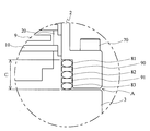
- FIG. 2 is an enlarged view of the tolerance and thermal deformation absorbing structure according to the embodiment of the present invention, indicated by B portion in FIG.
- the tolerance and thermal deformation absorption structure of the turbo molecular pump 1 according to the embodiment of the present invention includes a casing 2, a base 3, O-rings 81, 82, 83, spacers 90, 91. And a bolt 70.
- the tolerance and thermal deformation absorbing structure according to the present embodiment includes an O-ring (81, 82, 83) having a diameter of 5.33 mm and a plate-like spacer (90, 91) having a thickness of 6 mm. I have.
- a gap is provided between the casing 2 and the base 3, and O-rings (81, 82, 83) are arranged in the gap. Further, a spacer 90 and a spacer 91 are provided between the O-ring 81 and the O-ring 82 and between the O-ring 82 and the O-ring 83, respectively.
- the rounded O-rings (81, 82, 83) are arranged and sealed to each other, and there is a possibility that the intended sealing function cannot be fully achieved due to unstable contact between parts. Because there is a structure that sandwiches plate-shaped spacers (90, 91) between them, the structure that contacts the O-ring and the spacer instead of the O-rings stabilizes the contact between parts and improves the sealing function. This is to make it happen.
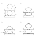
- FIGS. 3 (a) to 3 (d) show a stack of fixed wings 10 and O-rings (81, 82, 83) and spacers (90, 91) in the tolerance and thermal deformation absorbing structure according to the embodiment of the present invention.
- FIG. 4 is a conceptual diagram showing each state at various loads received from the fixed blade spacer 20. In FIG. 3, as an example, the O-rings 81 and 82 and the spacers 90 and 91 are extracted and described.
- FIG. 3A shows a state in which no load is applied to the O-rings (81, 82, 83) in the tolerance and thermal deformation absorbing structure according to the embodiment of the present invention. More specifically, before the casing 2 is covered in the assembly stage of the turbo molecular pump 1 according to the embodiment of the present invention, the O-rings (81, 82, 83) and the spacers (90, 91) are not loaded. The state under load is shown. In the present embodiment, the weights of the main bodies of the O-rings (81, 82, 83) and the main bodies of the spacers (90, 91) are not calculated as “loads” for convenience.
- FIG. 3B to 3D show a state in which the O-rings (81, 82, 83) are crushed due to the tolerance and thermal deformation absorbing structure according to the embodiment of the present invention. More specifically, FIG. 3B shows a state of the O-rings (81, 82, 83) having the design dimensions in the turbo molecular pump 1 according to the embodiment of the present invention. At this time, the collapse rate of the O-rings (81, 82, 83) is about 30%.
- FIG. 3C shows the tolerance and heat in the case where the height dimension due to the stacking of the fixed blade 10 and the fixed blade spacer 20 is minimized when the turbo molecular pump 1 according to the embodiment of the present invention is assembled.
- the state of the O-ring (81, 82, 83) disposed in the deformation absorbing structure is shown.
- the crushing rate of the O-rings (81, 82, 83) after the casing 2 and the base 3 are fastened with the bolt 70 becomes the maximum ( ⁇ : max). That is, since a large difference on the minus side occurs in the height dimension of the fixed blade 10 and the fixed blade spacer 20 stacked, the dimension C in FIG. 2 becomes smaller than the reference dimension, and as a result, the O-ring (81, The collapse rate of 82 and 83) is increased.
- FIG. 3D shows the tolerance and heat in the case where the height dimension due to the stacking of the fixed blade 10 and the fixed blade spacer 20 is maximized when the turbo molecular pump 1 according to the embodiment of the present invention is assembled.
- the state of the O-ring (81, 82, 83) disposed in the deformation absorbing structure is shown.
- the crushing rate of the O-rings (81, 82, 83) after the casing 2 and the base 3 are fastened with the bolt 70 is minimized ( ⁇ : min). That is, since a large plus difference is generated in the tolerance of stacking the fixed wing 10 and the fixed wing spacer 20, the dimension C in FIG. 2 becomes larger than the reference dimension, and as a result, the O-rings (81, 82, 83) the crushing rate is small.
- dH represents “the height fluctuation amount of the O-ring” and can be obtained by the following calculation formula (C).
- C)... DH (product variation + thermal deformation amount + component deformation amount) / N
- the height fluctuation amount (dH) of the O-ring (81, 82, 83) can be obtained only by the variation in the product of the fixed blade 10 or the fixed blade spacer 20.
- the tolerance and the thermal deformation absorbing structure according to the embodiment of the present invention can be calculated by using each component (the fixed wing 10 and the fixed wing spacer 20. Etc.) can be adapted to deformation due to thermal expansion.
- the limit crush rate ( ⁇ 1) of the O-ring which is a limit value at which the O-ring cracks or excessively deforms, is 40% as an example, and the crush rate required for the O-ring seal ( ⁇ 2) ) Is 20% as an example.
- the maximum collapse rate of the O-ring ( ⁇ : max) the limit collapse rate of the O-ring ( ⁇ 1), the minimum collapse rate of the O-ring ( ⁇ : min) and the O-ring seal
- D required crushing ratio
- an appropriate number of O-rings determined as described above are arranged in the gap between the casing 2 and the base 3 via a spacer, and then A plurality of O-rings (81, 82, 83) to be arranged can be configured to exhibit an appropriate repulsive force by fastening the gaps with bolts 70.
- the tolerance and thermal deformation absorbing structure in which the O-ring (81, 82, 83) is disposed can appropriately absorb the variation in the product of the fixed blade 10 or the fixed blade spacer 20 (tolerance absorption function). The difference in thermal expansion can be absorbed and the casing 2 and the base 3 can be properly sealed (surface sealing function).
- the collapse amount with respect to the diameter of the O-ring is expressed as a percentage, but the present invention is not limited to this.
- various representations (calculation methods) such as using an O-ring occupation amount with respect to the O-ring groove or using a contraction (compression) amount of the volume of the O-ring can be adopted.
- the number of O-rings arranged is three (three stages), but the number (number of stages) is not limited to this.
- Various combinations one, two, four, etc. may be considered depending on the clearance size for the tolerance and heat deformation absorbing structure and the type (performance) of the O-ring to be arranged.
- the fixed wing 10 uses a fixed wing having a large height dimensional tolerance (for example, a fixed wing formed by press molding), or is a full-stage wing type having a large number of stages of the fixed wing 10 and the fixed wing spacer 20.
- a large height dimensional tolerance for example, a fixed wing formed by press molding
- the O-ring to be disposed is multi-staged.
- the crushing margin of the O-ring per stage is configured to be less than the allowable strain.
- a spacer is provided between the O-rings arranged in multiple stages and the O-rings to prevent the O-rings from shifting.
- each component (the fixed blade 10 and the fixed blade spacer 20) has a small tolerance, and the fixed Even when the assembled dimensions of the blades 10 and the fixed blade spacers 20 are small, each component (the fixed blades 10 and the fixed blade spacers 20) has large tolerances. Even in the case where the dimension after the assembly of the stacked spacers 20 is large, the casing 2 and the base 3 are fastened with bolts 70 through the tolerance and heat deformation absorbing structure. The blade 10 and the fixed blade spacer 20 can be brought into close contact with each other without a gap. Therefore, the heat generated by the rotor blade 9 generated when the turbo molecular pump 1 operates can be efficiently radiated, and the risk of overheating of the turbo molecular pump 1 can be reduced.
- FIG. 4 is an enlarged view of a modified example of the tolerance and thermal deformation absorbing structure (B portion of FIG. 1) according to the above-described embodiment of the present invention.
- the tolerance and thermal deformation absorbing structure according to the present modification are similar to the embodiment shown in FIG. 2, the casing 2, the base 3, the O-rings 81, 82, 83, and the spacers. 90 and 91 and a bolt 70.
- a gap (gap) is provided in the base 3, and O-rings (81, 82, 83) are arranged in the gap, and the O-ring is arranged.
- a spacer 90 and a spacer 91 are provided between 81 and the O-ring 82 and between the O-ring 82 and the O-ring 83, respectively.
- a gap due to tolerance and a thermal deformation absorbing structure may be formed between the casing 2 and the base 3 as in the above-described embodiment of the present invention. Note that the above-described relational expressions and calculation formulas (A) to (E) are applied in the same way as the embodiment described with reference to FIGS.
- the casing 2 and the base 3 are face-sealed by the tolerance and the thermal deformation absorption structure provided between the casing 2 and the base 3. Therefore, the O-rings (81, 82, 83) disposed in the tolerance and thermal deformation absorbing structure are only loaded from above when assembling the turbo molecular pump 1, and force is applied in the shear direction to the side surface. Since it is not added, it is not necessary to apply vacuum grease for avoiding breakage due to the force in the shear direction.
- the turbo molecular pump 1 can assemble a vacuum pump without using vacuum grease, thereby avoiding the risk of vacuum contamination that can be expected when using vacuum grease. Is possible.
- the turbo molecular pump designed with a large dimensional tolerance of the fixed blade 10 and the fixed blade spacer 20 Appropriate tolerances and thermal deformation absorbing structures and face seal structures can be realized even for all-stage blade type turbo molecular pumps having a large number of stages.
- the present invention is not limited to this, and it varies depending on the diameter of the O-ring to be arranged and the size of the gap (gap) provided between the casing 2 and the base 3 (depth in the axial direction, width in the radial direction). It is possible to change the design. Alternatively, if appropriate stability can be maintained in the tolerance and thermal deformation absorption structure, a configuration in which only a plurality of O-rings are provided without providing a spacer between the O-rings and the O-rings is also possible. Is possible.
- a vacuum pump that can be assembled without using vacuum grease, and thus it is possible to avoid vacuum contamination due to vacuum grease.
- a vacuum pump is provided that can realize an appropriate tolerance, a thermal deformation absorbing structure, and a face seal structure even when the height dimensional tolerance of the fixed blade or the fixed blade spacer is increased. It becomes possible.
Landscapes
- Engineering & Computer Science (AREA)
- Mechanical Engineering (AREA)
- General Engineering & Computer Science (AREA)
- Non-Positive Displacement Air Blowers (AREA)
Abstract
真空グリスを塗布せず組み立てられ、また、適切な面シールが行える真空ポンプを提供することを目的とする。 ケーシングとベースとの間に、適切な反発力を有する程度のつぶししろで潰されるように構成されたOリングが配設された公差及び熱変形吸収構造を設ける。なお、真空ポンプにおいて、高さ寸法公差が大きい固定翼(例えば、プレス成型加工による固定翼など)を用いる場合や、回転翼及び固定翼の段数が多い全段翼式である場合であって、上述した公差及び熱変形吸収構造に配設されるOリングのつぶししろが、1段では、許容歪み(ひずみ)を越えてしまう場合は、配設するOリングを多段にして1段あたりのOリングのつぶししろを、Oリングに適切なシール性能を保てるつぶししろに構成する。また、この場合は、多段に配設されるOリングとOリングとの間にリング状のスペーサを設けて、当該Oリング同士のずれを防止する構成にする。
Description
本発明は真空ポンプに関し、特に、ケーシングとベースとを密着させるシール構造に、Oリングを用いるシール構造を備える真空ポンプに関する。
各種ある真空ポンプのうち、高真空の環境を実現するために多用されるものに全段翼(多段翼)式のターボ分子ポンプや、ねじ溝式ポンプがある。
こうした真空ポンプは、吸気口及び排気口を備えた外装体を形成するケーシングを有し、当該ケーシングの内部に当該真空ポンプに排気機能を発揮させる構造物が収納されている。この排気機能を発揮させる構造物は、大きく分けて、回転自在に軸支された回転部(ロータ部)とケーシングに対して固定された固定部(ステータ部)から構成されている。
ターボ分子ポンプの場合、回転部は、回転軸及びこの回転軸に固定されている回転体からなり、回転体には、放射状に設けられたロータ翼(動翼)が多段に配設されている。また、固定部には、ロータ翼に対して互い違いにステータ翼(静翼)が多段に配設されている。
また、回転軸を高速回転させるためのモータが設けられており、このモータの働きにより回転軸が高速回転すると、ロータ翼とステータ翼との相互作用により気体が吸気口から吸引され、排気口から排出されるようになっている。
こうした真空ポンプを用いて排気処理を行うことで内部が真空に保たれる真空装置のうち、より高い真空状態が求められる電子顕微鏡の測定室や表面分析装置などでは、一般的に多段翼式のターボ分子ポンプが利用される。
こうした真空ポンプは、吸気口及び排気口を備えた外装体を形成するケーシングを有し、当該ケーシングの内部に当該真空ポンプに排気機能を発揮させる構造物が収納されている。この排気機能を発揮させる構造物は、大きく分けて、回転自在に軸支された回転部(ロータ部)とケーシングに対して固定された固定部(ステータ部)から構成されている。
ターボ分子ポンプの場合、回転部は、回転軸及びこの回転軸に固定されている回転体からなり、回転体には、放射状に設けられたロータ翼(動翼)が多段に配設されている。また、固定部には、ロータ翼に対して互い違いにステータ翼(静翼)が多段に配設されている。
また、回転軸を高速回転させるためのモータが設けられており、このモータの働きにより回転軸が高速回転すると、ロータ翼とステータ翼との相互作用により気体が吸気口から吸引され、排気口から排出されるようになっている。
こうした真空ポンプを用いて排気処理を行うことで内部が真空に保たれる真空装置のうち、より高い真空状態が求められる電子顕微鏡の測定室や表面分析装置などでは、一般的に多段翼式のターボ分子ポンプが利用される。
図5は、従来の多段翼式のターボ分子ポンプ100を示した断面図である。
図5に示したように、多段翼式のターボ分子ポンプでは、吸気口4側から排気口6側の軸線方向に固定翼10と固定翼スペーサ20とが交互に積み上げられた構造になっている。このように固定翼10と固定翼スペーサ20とを交互に積み上げると、固定翼10と固定翼スペーサ20のそれぞれが有する寸法公差も同様に積み上がり、結果的に、ターボ分子ポンプとしての設計寸法の適切値(即ち、前もって定めてある寸法公差の許容範囲)から大幅にずれてしまうことがある。
ここで、公差とは、ターボ分子ポンプを構成する1つ1つの部品を製造する際に生じる、基準寸法からの+(プラス)又は-(マイナス)の寸法差であり、通常1つの部品に±数十マイクロメートル程度生じることが多い。
図5に示したターボ分子ポンプ100の製造に際して、固定翼10及び固定翼スペーサ20を組み立てる(積み上げる)とき、当該固定翼10及び固定翼スペーサ20の各々に生じた公差も積み重なる。その結果、大きな寸法ばらつき(積上ばらつき)が生じてしまう。
従来は、上述した寸法公差の積み上げ(積上ばらつき)を吸収するために、固定翼10と固定翼スペーサ20が所定の数だけ積み上げられた後のケーシング2とベース3との間に、計画的に隙間Aを設ける構造にし、積み上げた後にボルト70で締結し、更に、Oリング80を用いて真空シール(円筒シール方法)を行ってこの隙間Aで、寸法公差の積み上げを吸収していた。
ここで、隙間Aは、固定翼10や固定翼スペーサ20の各々の寸法公差が積み上がるために真空ポンプごとに一様ではない。そこで、図5のようにOリング80を用いて円筒シール構造にすることで、各々の寸法公差の積み上げにより、ばらつきが出る隙間Aの大小にかかわらず、Oリング80のつぶししろ(即ち、Oリングをどれだけ圧縮するかに関わる数値)を当該隙間Aと無関係に設定することができた。また、ポンプの運転時に生じる熱で、アルミ材である固定翼及び固定翼スペーサとステンレス材であるケーシングは、それぞれ熱膨張するが、アルミとステンレスの熱膨張の違いにより、それぞれ異なる変形量となる。ポンプの熱が上がった時、アルミの熱膨張率は、ステンレスの熱膨張率より大きいので隙間Aを広げる作用をする。
一方、Oリング溝にOリング80を配設した後にケーシング2を上から被せるこの構造では、ケーシング2を被せる際にケーシング2とOリング80とが接触してしまい、Oリング80はケーシング2から剪断方向に力を受ける。即ち、ケーシング2はOリング80を削り取るかのように接触しながら配設されていた。
そのため、従来では、この剪断方向に加わる力によってOリング80が破損するのを防ぐ目的で、Oリング80の表面に真空グリス(潤滑油)を塗る必要があった。
図5に示したように、多段翼式のターボ分子ポンプでは、吸気口4側から排気口6側の軸線方向に固定翼10と固定翼スペーサ20とが交互に積み上げられた構造になっている。このように固定翼10と固定翼スペーサ20とを交互に積み上げると、固定翼10と固定翼スペーサ20のそれぞれが有する寸法公差も同様に積み上がり、結果的に、ターボ分子ポンプとしての設計寸法の適切値(即ち、前もって定めてある寸法公差の許容範囲)から大幅にずれてしまうことがある。
ここで、公差とは、ターボ分子ポンプを構成する1つ1つの部品を製造する際に生じる、基準寸法からの+(プラス)又は-(マイナス)の寸法差であり、通常1つの部品に±数十マイクロメートル程度生じることが多い。
図5に示したターボ分子ポンプ100の製造に際して、固定翼10及び固定翼スペーサ20を組み立てる(積み上げる)とき、当該固定翼10及び固定翼スペーサ20の各々に生じた公差も積み重なる。その結果、大きな寸法ばらつき(積上ばらつき)が生じてしまう。
従来は、上述した寸法公差の積み上げ(積上ばらつき)を吸収するために、固定翼10と固定翼スペーサ20が所定の数だけ積み上げられた後のケーシング2とベース3との間に、計画的に隙間Aを設ける構造にし、積み上げた後にボルト70で締結し、更に、Oリング80を用いて真空シール(円筒シール方法)を行ってこの隙間Aで、寸法公差の積み上げを吸収していた。
ここで、隙間Aは、固定翼10や固定翼スペーサ20の各々の寸法公差が積み上がるために真空ポンプごとに一様ではない。そこで、図5のようにOリング80を用いて円筒シール構造にすることで、各々の寸法公差の積み上げにより、ばらつきが出る隙間Aの大小にかかわらず、Oリング80のつぶししろ(即ち、Oリングをどれだけ圧縮するかに関わる数値)を当該隙間Aと無関係に設定することができた。また、ポンプの運転時に生じる熱で、アルミ材である固定翼及び固定翼スペーサとステンレス材であるケーシングは、それぞれ熱膨張するが、アルミとステンレスの熱膨張の違いにより、それぞれ異なる変形量となる。ポンプの熱が上がった時、アルミの熱膨張率は、ステンレスの熱膨張率より大きいので隙間Aを広げる作用をする。
一方、Oリング溝にOリング80を配設した後にケーシング2を上から被せるこの構造では、ケーシング2を被せる際にケーシング2とOリング80とが接触してしまい、Oリング80はケーシング2から剪断方向に力を受ける。即ち、ケーシング2はOリング80を削り取るかのように接触しながら配設されていた。
そのため、従来では、この剪断方向に加わる力によってOリング80が破損するのを防ぐ目的で、Oリング80の表面に真空グリス(潤滑油)を塗る必要があった。
ここで、Oリング80の表面に真空グリスを塗布する場合に起こり得る真空汚染のリスクについて説明する。Oリング80に真空グリスを塗布した場合、Oリング80に塗布される真空グリスが、例えばケーシング2とベース3との間に形成される微小な隙間を通って排気経路に混ざり込むなどし、その経路を経て真空空間へ入り込んでしまう真空汚染のリスクが高まる。このように、Oリング80に真空グリスを塗布すると、真空ポンプに配設される装置における真空状態に影響を及ぼしてしまう虞があった。
そのため、Oリング80に真空グリスを塗布せずに真空シールをする必要があった。
そのため、Oリング80に真空グリスを塗布せずに真空シールをする必要があった。
特許文献1では、フランジ(21)とシャシ(5)とを真空密に結合するために、シールリング(21′)が配置されている。
特許文献2では、外側ステータ(4)を断熱材(8a)を介して外側ケーシング(7)にボルトで固定する技術が記載されている。
特許文献2では、外側ステータ(4)を断熱材(8a)を介して外側ケーシング(7)にボルトで固定する技術が記載されている。
特許文献1に記載されているように、Oリング溝を形成してシールをする面シール方法では、Oリングに剪断方向の圧力がかからないので真空グリスを利用せずに真空ポンプを組み立てることができる。
しかしながら、特許文献1に記載されているような面シールの技術では以下の課題があった。
(1)固定翼又は固定翼スペーサが有する高さ寸法公差を厳しく管理する必要が生じ、その結果、製造コストが上がってしまう。
(2)高さ寸法公差が大きい固定翼(例えば、プレス成型加工による固定翼)を使う場合や、段数の多い全段翼(多段翼)式のターボ分子ポンプの場合は、ともに積上ばらつきが大きくなるので、当該積上ばらつきを適切に吸収する構造を設ける必要があった。
より詳しくは、積上寸法が基準寸法よりも大きい場合、ケーシングとベースとの間に隙間が空いてOリングのつぶし量は小さくなる。その結果、Oリングに適切な反発力がなくなって面シール能力が低下し、リークする可能性が高くなってしまう。
一方、積上寸法が基準寸法よりも小さい場合、Oリングによる面シールは適切に働くが、ケーシングとベースとは密着しても、固定翼と固定翼スペーサとが密着しなくなってしまう可能性があった。その結果、回転翼と固定翼スペーサが充分冷却できず、回転翼から放熱された熱に対する適切な熱伝達(熱放射)が行われなくなり、真空ポンプのオーバーヒートの可能性が高くなる。
ポンプの温度が上がると、アルミ材での固定翼及び固定翼スペーサの熱膨張量がステンレス材であるケーシングのそれより大きいので、ケーシングとベースの間に隙間が空いて、Oリングつぶし量が小さくなる。その結果、Oリングに適切な反発力がなくなり、面シール能力が低下し、リークする可能性が高くなってしまう。
(3)Oリングのつぶし量が多くなると、Oリングの永久ひずみが大きくなり、シール能力が低下し、リークが発生する危険性が高くなる。
(1)固定翼又は固定翼スペーサが有する高さ寸法公差を厳しく管理する必要が生じ、その結果、製造コストが上がってしまう。
(2)高さ寸法公差が大きい固定翼(例えば、プレス成型加工による固定翼)を使う場合や、段数の多い全段翼(多段翼)式のターボ分子ポンプの場合は、ともに積上ばらつきが大きくなるので、当該積上ばらつきを適切に吸収する構造を設ける必要があった。
より詳しくは、積上寸法が基準寸法よりも大きい場合、ケーシングとベースとの間に隙間が空いてOリングのつぶし量は小さくなる。その結果、Oリングに適切な反発力がなくなって面シール能力が低下し、リークする可能性が高くなってしまう。
一方、積上寸法が基準寸法よりも小さい場合、Oリングによる面シールは適切に働くが、ケーシングとベースとは密着しても、固定翼と固定翼スペーサとが密着しなくなってしまう可能性があった。その結果、回転翼と固定翼スペーサが充分冷却できず、回転翼から放熱された熱に対する適切な熱伝達(熱放射)が行われなくなり、真空ポンプのオーバーヒートの可能性が高くなる。
ポンプの温度が上がると、アルミ材での固定翼及び固定翼スペーサの熱膨張量がステンレス材であるケーシングのそれより大きいので、ケーシングとベースの間に隙間が空いて、Oリングつぶし量が小さくなる。その結果、Oリングに適切な反発力がなくなり、面シール能力が低下し、リークする可能性が高くなってしまう。
(3)Oリングのつぶし量が多くなると、Oリングの永久ひずみが大きくなり、シール能力が低下し、リークが発生する危険性が高くなる。
また、特許文献2における断熱材(8a)は、外側ステータ(4)と内側ステータ(5)とを熱的に絶縁するためのものであり、ケーシングとベースを真空シールするためのOリングとは機能が異なる。また、断熱材(8a)だけではシール機能を果たしていない。
そこで、本発明は、真空ポンプにおいて、真空グリスを使用することなく組み立てが可能な真空ポンプを提供することを目的とする。また、固定翼又は固定翼スペーサの高さ寸法公差を大きく設計した場合でも、適切な面シール構造を実現することができる真空ポンプを提供することを目的とする。
請求項1記載の発明では、吸気口が形成された外装上体と、排気口が形成された外装下体と、前記外装上体の内側側面に配設される固定部と、前記固定部に固定され、前記外装上体の内周面から前記外装上体の中心に向かって複数枚配設された固定翼と、前記外装上体に内包され、回転自在に軸支された回転軸と、前記回転軸の周囲に放射状に複数枚配設された回転翼と、前記回転軸を回転させるモータと、前記外装上体、前記外装下体、複数のシール部材、前記各シール部材間に配設され当該シール部材を固定するスペーサ、及び、前記外装上体と前記外装下体とを締結する締結具で構成される公差及び熱変形吸収構造と、を備え、前記公差及び熱変形吸収構造は、複数の前記シール部材と前記スペーサが前記締結具の締結方向に交互に積層され、前記締結具が前記外装上体と前記外装下体とを締結する際、当該積層された前記シール部材及び前記スペーサに対して締結方向の押力を与えることで、前記固定部又は前記固定翼の積上ばらつきを吸収することを特徴とする真空ポンプを提供する。
請求項2記載の発明では、前記公差及び熱変形吸収構造に配設される複数の前記シール部材の個数は、複数配設される前記シール部材の各々がつぶれることによって、当該シール部材のシール性能を保てるように決められることを特徴とする請求項1に記載の真空ポンプを提供する。
請求項3記載の発明では、前記外装下体に複数の前記シール部材及び前記スペーサを収容する空隙を設け、前記空隙に前記シール部材及び前記スペーサを配設して前記公差及び熱変形吸収構造を形成することを特徴とする請求項1または請求項2に記載の真空ポンプを提供する。
請求項2記載の発明では、前記公差及び熱変形吸収構造に配設される複数の前記シール部材の個数は、複数配設される前記シール部材の各々がつぶれることによって、当該シール部材のシール性能を保てるように決められることを特徴とする請求項1に記載の真空ポンプを提供する。
請求項3記載の発明では、前記外装下体に複数の前記シール部材及び前記スペーサを収容する空隙を設け、前記空隙に前記シール部材及び前記スペーサを配設して前記公差及び熱変形吸収構造を形成することを特徴とする請求項1または請求項2に記載の真空ポンプを提供する。
本発明によれば、真空ポンプにおいて、真空グリスを使用することなく組み立てられ、また、固定翼又は固定翼スペーサの高さ寸法公差を大きく取っても適切な面シール構造が実現できる真空ポンプを提供することができる。
(i)実施形態の概要
本発明の実施形態の真空ポンプでは、ケーシングとベースとの間に、固定翼又は固定翼スペーサの公差を吸収するための公差及び熱変形吸収構造を設ける。
より詳しくは、この公差及び熱変形吸収構造では、ケーシングとベースとを面シールするためのOリングが配設されており、当該Oリングは、適切な反発力を有する程度のつぶししろ(例えば、10~30%)で潰されるように構成されている。なお、適切な反発力については後述する。
この公差及び熱変形吸収構造により、固定翼又は固定翼スペーサの公差を吸収できるとともに、ケーシングとベースとの適切な面シールを行うことができる。
なお、真空ポンプにおいて、高さ寸法公差が大きい固定翼(例えば、プレス成型加工による固定翼など)を用いる場合や、固定翼又は固定翼スペーサの段数が多い全段翼式である場合であって、上述した公差及び熱変形吸収構造に配設されるOリングのつぶししろが、1段のOリングでは、許容歪み(ひずみ)を越えてしまう場合は、配設するOリングを多段にして1段あたりのOリングのつぶししろを、Oリングに適切なシール性能を保てるつぶししろ(例えば、10~30%)に構成する。また、この場合は、多段に配設されるOリングとOリングとの間に板状のスペーサを設けて、当該Oリング同士のずれを防止する構成にする。
本発明の実施形態の真空ポンプでは、ケーシングとベースとの間に、固定翼又は固定翼スペーサの公差を吸収するための公差及び熱変形吸収構造を設ける。
より詳しくは、この公差及び熱変形吸収構造では、ケーシングとベースとを面シールするためのOリングが配設されており、当該Oリングは、適切な反発力を有する程度のつぶししろ(例えば、10~30%)で潰されるように構成されている。なお、適切な反発力については後述する。
この公差及び熱変形吸収構造により、固定翼又は固定翼スペーサの公差を吸収できるとともに、ケーシングとベースとの適切な面シールを行うことができる。
なお、真空ポンプにおいて、高さ寸法公差が大きい固定翼(例えば、プレス成型加工による固定翼など)を用いる場合や、固定翼又は固定翼スペーサの段数が多い全段翼式である場合であって、上述した公差及び熱変形吸収構造に配設されるOリングのつぶししろが、1段のOリングでは、許容歪み(ひずみ)を越えてしまう場合は、配設するOリングを多段にして1段あたりのOリングのつぶししろを、Oリングに適切なシール性能を保てるつぶししろ(例えば、10~30%)に構成する。また、この場合は、多段に配設されるOリングとOリングとの間に板状のスペーサを設けて、当該Oリング同士のずれを防止する構成にする。
(ii)実施形態の詳細
以下、本発明の好適な実施の形態について、図1~図4を参照して詳細に説明する。
なお、本実施形態では、真空ポンプの一例として、回転翼及び固定翼の段数が多い全段翼(多段翼)式のターボ分子ポンプを用いて説明する。
なお、本実施形態は、ターボ分子ポンプ部とねじ溝式ポンプ部を備えた、いわゆる複合型のターボ分子ポンプに適用しても良い。
以下、本発明の好適な実施の形態について、図1~図4を参照して詳細に説明する。
なお、本実施形態では、真空ポンプの一例として、回転翼及び固定翼の段数が多い全段翼(多段翼)式のターボ分子ポンプを用いて説明する。
なお、本実施形態は、ターボ分子ポンプ部とねじ溝式ポンプ部を備えた、いわゆる複合型のターボ分子ポンプに適用しても良い。
図1は、本発明の実施形態に係る公差及び熱変形吸収構造を備えたターボ分子ポンプ1の概略構成例を示した図である。なお、図1は、ターボ分子ポンプ1の軸線方向の断面図を示している。
ターボ分子ポンプ1の外装体を形成するケーシング2は、略円筒状の形状をしており、ケーシング2の下部(排気口6側)に設けられたベース3と共にターボ分子ポンプ1の筐体を構成している。そして、この筐体の内部には、ターボ分子ポンプ1に排気機能を発揮させる構造物である気体移送機構が収納されている。
この気体移送機構は、大きく分けて、回転自在に軸支された回転部と筐体に対して固定された固定部から構成されている。
ターボ分子ポンプ1の外装体を形成するケーシング2は、略円筒状の形状をしており、ケーシング2の下部(排気口6側)に設けられたベース3と共にターボ分子ポンプ1の筐体を構成している。そして、この筐体の内部には、ターボ分子ポンプ1に排気機能を発揮させる構造物である気体移送機構が収納されている。
この気体移送機構は、大きく分けて、回転自在に軸支された回転部と筐体に対して固定された固定部から構成されている。
ケーシング2の端部には、当該ターボ分子ポンプ1へ気体を導入するための吸気口4が形成されている。また、ケーシング2の吸気口4側の端面には、外周側へ張り出したフランジ部5が形成されている。
また、ベース3には、当該ターボ分子ポンプ1から気体を排気するための排気口6が形成されている。
また、ベース3には、当該ターボ分子ポンプ1から気体を排気するための排気口6が形成されている。
回転部は、回転軸であるシャフト7、このシャフト7に配設されたロータ8、ロータ8に設けられた複数枚の回転翼9などから構成されている。なお、シャフト7及びロータ8によってロータ部が構成されている。
各回転翼9は、シャフト7の軸線に垂直な平面から所定の角度だけ傾斜してシャフト7から放射状に伸びたブレードで構成されている。
各回転翼9は、シャフト7の軸線に垂直な平面から所定の角度だけ傾斜してシャフト7から放射状に伸びたブレードで構成されている。
シャフト7の軸線方向中程には、シャフト7を高速回転させるためのモータ部60が設けられ、ステータコラム50に内包されている。
更に、シャフト7のモータ部60に対して吸気口4側及び排気口6側には、シャフト7をラジアル方向(径方向)に非接触で軸支するための径方向磁気軸受装置30、31、シャフト7の下端には、シャフト7を軸線方向(アキシャル方向)に非接触で軸支するための軸方向磁気軸受装置40が設けられている。
更に、シャフト7のモータ部60に対して吸気口4側及び排気口6側には、シャフト7をラジアル方向(径方向)に非接触で軸支するための径方向磁気軸受装置30、31、シャフト7の下端には、シャフト7を軸線方向(アキシャル方向)に非接触で軸支するための軸方向磁気軸受装置40が設けられている。
筐体の内周側には、固定部が形成されている。この固定部は、吸気口4側から排気口6側にわたって多段に設けられた複数枚の固定翼10が設けられており、各固定翼10は、シャフト7の軸線に垂直な平面から所定の角度だけ傾斜して筐体の内周面からシャフト7に向かって伸びたブレードで構成されている。
各段の固定翼10は、円筒形状をした固定翼スペーサ20により互いに隔てられて固定されている。
本実施形態に係る多段翼式のターボ分子ポンプ部では、固定翼10と、回転翼9とが互い違いに配置され、軸線方向に複数段形成されている。
上述した構成により、ターボ分子ポンプ1は吸気口4から吸引したガスを圧縮し、排気口6から排出することで、当該ターボ分子ポンプ1に配設される真空室(図示しない)内の真空排気処理を行うようになっている。
各段の固定翼10は、円筒形状をした固定翼スペーサ20により互いに隔てられて固定されている。
本実施形態に係る多段翼式のターボ分子ポンプ部では、固定翼10と、回転翼9とが互い違いに配置され、軸線方向に複数段形成されている。
上述した構成により、ターボ分子ポンプ1は吸気口4から吸引したガスを圧縮し、排気口6から排出することで、当該ターボ分子ポンプ1に配設される真空室(図示しない)内の真空排気処理を行うようになっている。
(公差及び熱変形吸収構造)
図2は、図1においてB部で示した、本発明の実施形態に係る公差及び熱変形吸収構造の拡大図である。
図2に示したように、本発明の実施形態に係るターボ分子ポンプ1が有する公差及び熱変形吸収構造は、ケーシング2と、ベース3と、Oリング81、82、83と、スペーサ90、91と、ボルト70とで構成される。
なお、本実施形態に係る公差及び熱変形吸収構造は、一例として、直径が5.33ミリのOリング(81、82、83)と、厚さ6ミリの板状スペーサ(90、91)を備えている。
本発明の実施形態に係るターボ分子ポンプ1は、ケーシング2とベース3との間に空隙(隙間)が設けられ、当該隙間にOリング(81、82、83)が配設されている。
更に、Oリング81及びOリング82の間、並びに、Oリング82及びOリング83の間には、スペーサ90及びスペーサ91が各々備えられている。これは、丸みを帯びたOリング(81、82、83)同士を配設してシールする構造では部品同士の接触が不安定になるなどして目的とするシール機能が充分に発揮できない可能性があるので、板状のスペーサ(90、91)を間に挟む構成にしてOリング同士ではなくOリングとスペーサとを接触させる構成にすることで部品同士の接触を安定させ、シール機能を向上させるためである。
図2は、図1においてB部で示した、本発明の実施形態に係る公差及び熱変形吸収構造の拡大図である。
図2に示したように、本発明の実施形態に係るターボ分子ポンプ1が有する公差及び熱変形吸収構造は、ケーシング2と、ベース3と、Oリング81、82、83と、スペーサ90、91と、ボルト70とで構成される。
なお、本実施形態に係る公差及び熱変形吸収構造は、一例として、直径が5.33ミリのOリング(81、82、83)と、厚さ6ミリの板状スペーサ(90、91)を備えている。
本発明の実施形態に係るターボ分子ポンプ1は、ケーシング2とベース3との間に空隙(隙間)が設けられ、当該隙間にOリング(81、82、83)が配設されている。
更に、Oリング81及びOリング82の間、並びに、Oリング82及びOリング83の間には、スペーサ90及びスペーサ91が各々備えられている。これは、丸みを帯びたOリング(81、82、83)同士を配設してシールする構造では部品同士の接触が不安定になるなどして目的とするシール機能が充分に発揮できない可能性があるので、板状のスペーサ(90、91)を間に挟む構成にしてOリング同士ではなくOリングとスペーサとを接触させる構成にすることで部品同士の接触を安定させ、シール機能を向上させるためである。
次に、本発明の実施形態に係るターボ分子ポンプ1が備える公差及び熱変形吸収構造が、固定翼10又は固定翼スペーサ20の積上ばらつき及び熱変形をどのように吸収するのか、また、ケーシング2とベース3とをどのようにシールするのかについて説明する。
図3(a)~(d)は、本発明の実施形態に係る公差及び熱変形吸収構造におけるOリング(81、82、83)とスペーサ(90、91)の、積み上げられた固定翼10及び固定翼スペーサ20から受ける様々な負荷時における各状態を示した概念図である。
なお、図3では、一例として、Oリング81、82及びスペーサ90、91を抜粋して示して説明している。
図3(a)~(d)は、本発明の実施形態に係る公差及び熱変形吸収構造におけるOリング(81、82、83)とスペーサ(90、91)の、積み上げられた固定翼10及び固定翼スペーサ20から受ける様々な負荷時における各状態を示した概念図である。
なお、図3では、一例として、Oリング81、82及びスペーサ90、91を抜粋して示して説明している。
図3(a)は、本発明の実施形態に係る公差及び熱変形吸収構造において、Oリング(81、82、83)に負荷がかかっていない状態を示している。より詳しくは、本発明の実施形態に係るターボ分子ポンプ1の組立段階においてケーシング2を被せる前であり、Oリング(81、82、83)及びスペーサ(90、91)が負荷を受けていない無負荷時の状態が示されている。なお、本実施形態では、Oリング(81、82、83)の本体、及び、スペーサ(90、91)の本体の重さは便宜上「負荷」としては計算していない。
図3(b)~(d)は、本発明の実施形態に係る公差及び熱変形吸収構造において、Oリング(81、82、83)に負荷がかかり潰れている状態を示している。
より詳しくは、図3(b)は、本発明の実施形態に係るターボ分子ポンプ1における、設計寸法のOリング(81、82、83)の状態が示されている。このときのOリング(81、82、83)のつぶれ率は、30%程度である。
図3(b)~(d)は、本発明の実施形態に係る公差及び熱変形吸収構造において、Oリング(81、82、83)に負荷がかかり潰れている状態を示している。
より詳しくは、図3(b)は、本発明の実施形態に係るターボ分子ポンプ1における、設計寸法のOリング(81、82、83)の状態が示されている。このときのOリング(81、82、83)のつぶれ率は、30%程度である。
図3(c)は、本発明の実施形態に係るターボ分子ポンプ1を組み立てた際に、固定翼10と固定翼スペーサ20との積上げによる高さ寸法が最小になった場合における、公差及び熱変形吸収構造に配設されたOリング(81、82、83)の状態を示している。
この場合、ボルト70でケーシング2とベース3を締結した後のOリング(81、82、83)のつぶれ率は最大(ε:max)になる。即ち、固定翼10と固定翼スペーサ20とを積み上げた高さ寸法にマイナス側の大きな差が生じているので、図2の寸法Cは、基準寸法よりも小さくなり、結果としてOリング(81、82、83)のつぶれ率は大きくなる。
この場合、ボルト70でケーシング2とベース3を締結した後のOリング(81、82、83)のつぶれ率は最大(ε:max)になる。即ち、固定翼10と固定翼スペーサ20とを積み上げた高さ寸法にマイナス側の大きな差が生じているので、図2の寸法Cは、基準寸法よりも小さくなり、結果としてOリング(81、82、83)のつぶれ率は大きくなる。
図3(d)は、本発明の実施形態に係るターボ分子ポンプ1を組み立てた際に、固定翼10と固定翼スペーサ20との積上げによる高さ寸法が最大になった場合における、公差及び熱変形吸収構造に配設されたOリング(81、82、83)の状態を示している。この場合、ボルト70でケーシング2とベース3を締結した後のOリング(81、82、83)のつぶれ率は最小(ε:min)になる。即ち、固定翼10と固定翼スペーサ20とを積み上げた公差にプラス側の大きな差が生じているので、図2の寸法Cは、基準寸法よりも大きくなり、結果としてOリング(81、82、83)のつぶれ率は小さくなる。
本発明の実施形態に係る公差及び熱変形吸収構造に備わるOリング(81、82、83)は、以下に説明するように、適切な反発力を有する程度のつぶししろ(圧縮可能な許容量、許容比率)で潰されるように構成されている。
より具体的には、本発明の実施形態に係る公差及び熱変形吸収構造に配設される各Oリング(81、82、83)の、最大つぶれ率及び最小つぶれ率は以下の計算式(A)(B)に基づいて算出する。
(A)…Oリングの最大つぶれ率(ε:max)={D-(H-dH)}/D
(B)…Oリングの最小つぶれ率(ε:min)={D-(H+dH)}/D
但し、このとき、「dH」は「Oリングの高さ変動量」を表しており、以下の計算式(C)で求めることができる。
(C)…dH=(積上ばらつき+熱変形量+部品の変形量)/N
上述した計算式(C)にあるように、本実施形態では、Oリング(81、82、83)の高さ変動量(dH)は、固定翼10又は固定翼スペーサ20の積上ばらつきだけではなく、当該固定翼10及び固定翼スペーサ20の熱変形量も考慮して算出されるので、本発明の実施形態に係る公差及び熱変形吸収構造は、各部品(固定翼10や固定翼スペーサ20など)の熱膨張による変形にも対応可能な構成になっている。
より具体的には、本発明の実施形態に係る公差及び熱変形吸収構造に配設される各Oリング(81、82、83)の、最大つぶれ率及び最小つぶれ率は以下の計算式(A)(B)に基づいて算出する。
(A)…Oリングの最大つぶれ率(ε:max)={D-(H-dH)}/D
(B)…Oリングの最小つぶれ率(ε:min)={D-(H+dH)}/D
但し、このとき、「dH」は「Oリングの高さ変動量」を表しており、以下の計算式(C)で求めることができる。
(C)…dH=(積上ばらつき+熱変形量+部品の変形量)/N
上述した計算式(C)にあるように、本実施形態では、Oリング(81、82、83)の高さ変動量(dH)は、固定翼10又は固定翼スペーサ20の積上ばらつきだけではなく、当該固定翼10及び固定翼スペーサ20の熱変形量も考慮して算出されるので、本発明の実施形態に係る公差及び熱変形吸収構造は、各部品(固定翼10や固定翼スペーサ20など)の熱膨張による変形にも対応可能な構成になっている。
なお、本発明の実施形態では、Oリングの割れや過度な変形が起こる限界値であるOリングの限界つぶれ率(ε1)を一例として40%、また、Oリングシールに必要なつぶれ率(ε2)を一例として20%とし、更に、Oリングの最大つぶれ率(ε:max)とOリングの限界つぶれ率(ε1)、及び、Oリングの最小つぶれ率(ε:min)とOリングシールに必要なつぶれ率(ε2)との間には以下の関係式(D)かつ(E)が成り立つ構成になっている。
(D)…Oリングの限界つぶれ率(ε1)<Oリングの最大つぶれ率(ε:max)
(E)…Oリングシールに必要なつぶれ率(ε2)<Oリングの最小つぶれ率(ε:min)
なお、上記各式で用いた「D」「H」「N」は以下の数値である。
D…Oリング(81、82、83)の無負荷状態における直径
H…Oリング(81、82、83)の高さ変動が無い状態におけるつぶれ量の設計寸法
N…Oリング(81、82、83)を積み上げた個数
(D)…Oリングの限界つぶれ率(ε1)<Oリングの最大つぶれ率(ε:max)
(E)…Oリングシールに必要なつぶれ率(ε2)<Oリングの最小つぶれ率(ε:min)
なお、上記各式で用いた「D」「H」「N」は以下の数値である。
D…Oリング(81、82、83)の無負荷状態における直径
H…Oリング(81、82、83)の高さ変動が無い状態におけるつぶれ量の設計寸法
N…Oリング(81、82、83)を積み上げた個数
本発明の実施形態に係る公差及び熱変形吸収構造では、上述した各式(計算式、関係式)を満たし、配設されるOリングが有する適正値(18~42%)と、当該Oリングが配設される公差及び熱変形吸収構造のためにターボ分子ポンプ1に確保される隙間寸法と、の両方を考慮した結果、配設されるOリングは3個が適切であることが導き出された。
本実施形態に係る公差及び熱変形吸収構造は、ケーシング2とベース3との間の隙間に、上述のようにして決定した適切な個数のOリングをスペーサを介して配設し、その後、当該隙間をボルト70で締結することで、配設される複数のOリング(81、82、83)が適切な反発力を発揮できるように構成されている。
その結果、当該Oリング(81、82、83)が配設される公差及び熱変形吸収構造は、固定翼10又は固定翼スペーサ20の積上ばらつきを適切に吸収できる(公差吸収機能)と同時に、熱膨張量の差を吸収し、ケーシング2とベース3とを適切にシールすることができる(面シール機能)。
本実施形態に係る公差及び熱変形吸収構造は、ケーシング2とベース3との間の隙間に、上述のようにして決定した適切な個数のOリングをスペーサを介して配設し、その後、当該隙間をボルト70で締結することで、配設される複数のOリング(81、82、83)が適切な反発力を発揮できるように構成されている。
その結果、当該Oリング(81、82、83)が配設される公差及び熱変形吸収構造は、固定翼10又は固定翼スペーサ20の積上ばらつきを適切に吸収できる(公差吸収機能)と同時に、熱膨張量の差を吸収し、ケーシング2とベース3とを適切にシールすることができる(面シール機能)。
なお、本実施形態では、一例として、Oリングの直径に対するつぶれ量を百分率(パーセンテージ)で表しているが、これに限ることはない。例えば、Oリング溝に対するOリングの占有量を用いたり、或いはOリングの体積の縮み(圧縮)量を用いるなど、様々な表し方(算出方法)が採用し得る。
また、本実施形態では配設されるOリングの個数は3個(3段)であるが、個数(段数)はこれに限られることはない。公差及び熱変形吸収構造のための隙間寸法や配設されるOリングの種類(性能)によって様々な組合せ(1個、2個、4個など)が考えられ得る。
つまり、固定翼10に、高さ寸法公差が大きい固定翼(例えば、プレス成型加工による固定翼など)を用いる場合や、固定翼10及び固定翼スペーサ20の段数が多い全段翼式である場合であって、上述した公差及び熱変形吸収構造に配設されるOリングのつぶししろが、1段のOリングでは、許容歪み(ひずみ)を越えてしまう場合は、配設するOリングを多段にして1段あたりのOリングのつぶししろを許容歪み以下に抑えるように構成する。そして、多段に配設されるOリングとOリングとの間にスペーサを設けて、当該Oリング同士のずれを防止する構成にする。
また、本実施形態では配設されるOリングの個数は3個(3段)であるが、個数(段数)はこれに限られることはない。公差及び熱変形吸収構造のための隙間寸法や配設されるOリングの種類(性能)によって様々な組合せ(1個、2個、4個など)が考えられ得る。
つまり、固定翼10に、高さ寸法公差が大きい固定翼(例えば、プレス成型加工による固定翼など)を用いる場合や、固定翼10及び固定翼スペーサ20の段数が多い全段翼式である場合であって、上述した公差及び熱変形吸収構造に配設されるOリングのつぶししろが、1段のOリングでは、許容歪み(ひずみ)を越えてしまう場合は、配設するOリングを多段にして1段あたりのOリングのつぶししろを許容歪み以下に抑えるように構成する。そして、多段に配設されるOリングとOリングとの間にスペーサを設けて、当該Oリング同士のずれを防止する構成にする。
また、上述した構成にすることで、本発明の実施形態に係る公差及び熱変形吸収構造を有するターボ分子ポンプ1では、部品(固定翼10や固定翼スペーサ20)の各公差が小さく、当該固定翼10及び固定翼スペーサ20を積み上げた組み立て後の寸法が小さく構成された場合でも、また逆に、部品(固定翼10や固定翼スペーサ20)の各公差が大きく、当該固定翼10及び固定翼スペーサ20を積み上げた組み立て後の寸法が大きく構成された場合でも、どちらの場合であっても、公差及び熱変形吸収構造を介してケーシング2とベース3とをボルト70で締結することにより、固定翼10及び固定翼スペーサ20を隙間無く密着させることができる。
そのため、ターボ分子ポンプ1が作動する際に発生する回転翼9の発熱を効率よく放熱することができ、ターボ分子ポンプ1のオーバーヒートのリスクを低減させることができる。
そのため、ターボ分子ポンプ1が作動する際に発生する回転翼9の発熱を効率よく放熱することができ、ターボ分子ポンプ1のオーバーヒートのリスクを低減させることができる。
(公差及び熱変形吸収構造の変形例)
次に、本発明の実施形態の変形例について、図4を参照して説明する。
図4は、上述した本発明の実施形態に係る公差及び熱変形吸収構造(図1のB部)の変形例の拡大図である。
図4に示したように、本変形例に係る公差及び熱変形吸収構造は、図2で示した実施形態と同様に、ケーシング2と、ベース3と、Oリング81、82、83と、スペーサ90、91と、ボルト70とで構成される。
ここで、本変形例に係る公差及び熱変形吸収構造は、ベース3に空隙(隙間)が設けられ、当該隙間にOリング(81、82、83)が配設され、配設されるOリング81及びOリング82の間、並びに、Oリング82及びOリング83の間に、スペーサ90及びスペーサ91が各々備えられる。図示されていないが、先述した本発明の実施形態と同様に、Oリングをつぶした後には、ケーシング2とベース3との間に公差及び熱変形吸収構造による隙間が形成されてもよい。
なお、先述した各関係式及び計算式(A)~(E)が適用される点などは図2及び図3を用いて説明した実施形態と同じである。
次に、本発明の実施形態の変形例について、図4を参照して説明する。
図4は、上述した本発明の実施形態に係る公差及び熱変形吸収構造(図1のB部)の変形例の拡大図である。
図4に示したように、本変形例に係る公差及び熱変形吸収構造は、図2で示した実施形態と同様に、ケーシング2と、ベース3と、Oリング81、82、83と、スペーサ90、91と、ボルト70とで構成される。
ここで、本変形例に係る公差及び熱変形吸収構造は、ベース3に空隙(隙間)が設けられ、当該隙間にOリング(81、82、83)が配設され、配設されるOリング81及びOリング82の間、並びに、Oリング82及びOリング83の間に、スペーサ90及びスペーサ91が各々備えられる。図示されていないが、先述した本発明の実施形態と同様に、Oリングをつぶした後には、ケーシング2とベース3との間に公差及び熱変形吸収構造による隙間が形成されてもよい。
なお、先述した各関係式及び計算式(A)~(E)が適用される点などは図2及び図3を用いて説明した実施形態と同じである。
上述したように、本発明の実施形態及び変形例に係るターボ分子ポンプ1では、ケーシング2とベース3との間に設けた公差及び熱変形吸収構造によって当該ケーシング2とベース3とを面シールするので、公差及び熱変形吸収構造に配設されるOリング(81、82、83)は、ターボ分子ポンプ1を組み立てる際に上から加重されるのみであり、側面に対して剪断方向に力が加わることがないため、剪断方向の力に因る破損を回避させるための真空グリスを塗布しておく必要がない。
その結果、本発明の実施形態に係るターボ分子ポンプ1は、真空グリスを使用せずに真空ポンプを組み立てることができるので、真空グリスを使用した場合に予想し得る真空汚染のリスクを回避することが可能になる。
このように、本発明の実施形態に係る公差及び熱変形吸収構造によれば、固定翼10及び固定翼スペーサ20の高さ寸法公差を大きく取って設計されたターボ分子ポンプや、固定翼10の段数が多い全段翼式のターボ分子ポンプに対しても、適切な公差及び熱変形吸収構造及び面シール構造を実現することが可能になる。
その結果、本発明の実施形態に係るターボ分子ポンプ1は、真空グリスを使用せずに真空ポンプを組み立てることができるので、真空グリスを使用した場合に予想し得る真空汚染のリスクを回避することが可能になる。
このように、本発明の実施形態に係る公差及び熱変形吸収構造によれば、固定翼10及び固定翼スペーサ20の高さ寸法公差を大きく取って設計されたターボ分子ポンプや、固定翼10の段数が多い全段翼式のターボ分子ポンプに対しても、適切な公差及び熱変形吸収構造及び面シール構造を実現することが可能になる。
なお、本発明の実施形態では、上述のように、直径5.33ミリのOリングを3個(3段)、及び厚さ6ミリのスペーサを2個(2段)配設する構成としたが、これに限られることはなく、配設するOリングの直径や、ケーシング2とベース3との間に設けるギャップ(隙間)の大きさ(軸方向の深さ、径方向の幅)によって種々に設計変更することが可能である。
或いは、公差及び熱変形吸収構造において適切な安定性が保てるのであれば、OリングとOリングとの間にスペーサを配設することなく、複数のOリングのみを配設する構成にすることも可能である。
或いは、公差及び熱変形吸収構造において適切な安定性が保てるのであれば、OリングとOリングとの間にスペーサを配設することなく、複数のOリングのみを配設する構成にすることも可能である。
このように、本発明の実施形態によれば、真空グリスを使用せずに組み立てることができる真空ポンプを提供することができるので、真空グリスによる真空汚染を回避することが可能になる。
また、真空ポンプにおいて、固定翼又は固定翼スペーサの高さ寸法公差を大きく取った場合であっても、適切な公差及び熱変形吸収構造及び面シール構造を実現することができる真空ポンプを提供することが可能になる。
また、真空ポンプにおいて、固定翼又は固定翼スペーサの高さ寸法公差を大きく取った場合であっても、適切な公差及び熱変形吸収構造及び面シール構造を実現することができる真空ポンプを提供することが可能になる。
1 ターボ分子ポンプ
2 ケーシング
3 ベース
4 吸気口
5 フランジ部
6 排気口
7 シャフト
8 ロータ
9 回転翼
10 固定翼
20 固定翼スペーサ
30、31 径方向磁気軸受装置
40 軸方向磁気軸受装置
50 ステータコラム
60 モータ部
70 ボルト
80、81、82、83 Oリング
90、91 スペーサ
100 ターボ分子ポンプ
2 ケーシング
3 ベース
4 吸気口
5 フランジ部
6 排気口
7 シャフト
8 ロータ
9 回転翼
10 固定翼
20 固定翼スペーサ
30、31 径方向磁気軸受装置
40 軸方向磁気軸受装置
50 ステータコラム
60 モータ部
70 ボルト
80、81、82、83 Oリング
90、91 スペーサ
100 ターボ分子ポンプ
Claims (3)
- 吸気口が形成された外装上体と、
排気口が形成された外装下体と、
前記外装上体の内側側面に配設される固定部と、
前記固定部に固定され、前記外装上体の内周面から前記外装上体の中心に向かって複数枚配設された固定翼と、
前記外装上体に内包され、回転自在に軸支された回転軸と、
前記回転軸の周囲に放射状に複数枚配設された回転翼と、
前記回転軸を回転させるモータと、
前記外装上体、前記外装下体、複数のシール部材、前記各シール部材間に配設され当該シール部材を固定するスペーサ、及び、前記外装上体と前記外装下体とを締結する締結具で構成される公差及び熱変形吸収構造と、を備え、
前記公差及び熱変形吸収構造は、複数の前記シール部材と前記スペーサが前記締結具の締結方向に交互に積層され、前記締結具が前記外装上体と前記外装下体とを締結する際、当該積層された前記シール部材及び前記スペーサに対して締結方向の押力を与えることで、前記固定部又は前記固定翼の積上ばらつきを吸収することを特徴とする真空ポンプ。 - 前記公差及び熱変形吸収構造に配設される複数の前記シール部材の個数は、複数配設される前記シール部材の各々がつぶれることによって、当該シール部材のシール性能を保てるように決められることを特徴とする請求項1に記載の真空ポンプ。
- 前記外装下体に複数の前記シール部材及び前記スペーサを収容する空隙を設け、前記空隙に前記シール部材及び前記スペーサを配設して前記公差及び熱変形吸収構造を形成することを特徴とする請求項1または請求項2に記載の真空ポンプ。
Priority Applications (1)
| Application Number | Priority Date | Filing Date | Title |
|---|---|---|---|
| JP2013517937A JP6113071B2 (ja) | 2011-06-03 | 2012-05-07 | 真空ポンプ |
Applications Claiming Priority (2)
| Application Number | Priority Date | Filing Date | Title |
|---|---|---|---|
| JP2011-125766 | 2011-06-03 | ||
| JP2011125766 | 2011-06-03 |
Publications (1)
| Publication Number | Publication Date |
|---|---|
| WO2012165105A1 true WO2012165105A1 (ja) | 2012-12-06 |
Family
ID=47258969
Family Applications (1)
| Application Number | Title | Priority Date | Filing Date |
|---|---|---|---|
| PCT/JP2012/061672 Ceased WO2012165105A1 (ja) | 2011-06-03 | 2012-05-07 | 真空ポンプ |
Country Status (2)
| Country | Link |
|---|---|
| JP (1) | JP6113071B2 (ja) |
| WO (1) | WO2012165105A1 (ja) |
Cited By (4)
| Publication number | Priority date | Publication date | Assignee | Title |
|---|---|---|---|---|
| JP2016176340A (ja) * | 2015-03-18 | 2016-10-06 | 株式会社島津製作所 | ターボ分子ポンプ |
| GB2553323A (en) * | 2016-09-01 | 2018-03-07 | Edwards Ltd | Pump assemblies with sealing |
| CN108506225A (zh) * | 2017-02-27 | 2018-09-07 | 株式会社岛津制作所 | 电源一体型真空泵 |
| EP4379215A4 (en) * | 2021-07-26 | 2025-07-02 | Edwards Japan Ltd | VACUUM PUMP |
Citations (4)
| Publication number | Priority date | Publication date | Assignee | Title |
|---|---|---|---|---|
| JP2001153087A (ja) * | 1999-10-28 | 2001-06-05 | Pfeiffer Vacuum Gmbh | ターボ分子ポンプ |
| JP2001271786A (ja) * | 2000-03-02 | 2001-10-05 | Pfeiffer Vacuum Gmbh | ターボ分子ポンプ |
| WO2010007975A1 (ja) * | 2008-07-14 | 2010-01-21 | エドワーズ株式会社 | 真空ポンプ |
| WO2010016141A1 (ja) * | 2008-08-08 | 2010-02-11 | 株式会社島津製作所 | 回転真空ポンプ |
Family Cites Families (3)
| Publication number | Priority date | Publication date | Assignee | Title |
|---|---|---|---|---|
| US6508631B1 (en) * | 1999-11-18 | 2003-01-21 | Mks Instruments, Inc. | Radial flow turbomolecular vacuum pump |
| DE102007044945A1 (de) * | 2007-09-20 | 2009-04-09 | Pfeiffer Vacuum Gmbh | Vakuumpumpe |
| JP5115134B2 (ja) * | 2007-10-12 | 2013-01-09 | 株式会社島津製作所 | 真空ポンプ装置 |
-
2012
- 2012-05-07 WO PCT/JP2012/061672 patent/WO2012165105A1/ja not_active Ceased
- 2012-05-07 JP JP2013517937A patent/JP6113071B2/ja not_active Expired - Fee Related
Patent Citations (4)
| Publication number | Priority date | Publication date | Assignee | Title |
|---|---|---|---|---|
| JP2001153087A (ja) * | 1999-10-28 | 2001-06-05 | Pfeiffer Vacuum Gmbh | ターボ分子ポンプ |
| JP2001271786A (ja) * | 2000-03-02 | 2001-10-05 | Pfeiffer Vacuum Gmbh | ターボ分子ポンプ |
| WO2010007975A1 (ja) * | 2008-07-14 | 2010-01-21 | エドワーズ株式会社 | 真空ポンプ |
| WO2010016141A1 (ja) * | 2008-08-08 | 2010-02-11 | 株式会社島津製作所 | 回転真空ポンプ |
Cited By (6)
| Publication number | Priority date | Publication date | Assignee | Title |
|---|---|---|---|---|
| JP2016176340A (ja) * | 2015-03-18 | 2016-10-06 | 株式会社島津製作所 | ターボ分子ポンプ |
| GB2553323A (en) * | 2016-09-01 | 2018-03-07 | Edwards Ltd | Pump assemblies with sealing |
| WO2018042150A1 (en) * | 2016-09-01 | 2018-03-08 | Edwards Limited | Pump assemblies with sealing |
| CN108506225A (zh) * | 2017-02-27 | 2018-09-07 | 株式会社岛津制作所 | 电源一体型真空泵 |
| CN108506225B (zh) * | 2017-02-27 | 2020-05-08 | 株式会社岛津制作所 | 电源一体型真空泵 |
| EP4379215A4 (en) * | 2021-07-26 | 2025-07-02 | Edwards Japan Ltd | VACUUM PUMP |
Also Published As
| Publication number | Publication date |
|---|---|
| JP6113071B2 (ja) | 2017-04-12 |
| JPWO2012165105A1 (ja) | 2015-02-23 |
Similar Documents
| Publication | Publication Date | Title |
|---|---|---|
| JP3961273B2 (ja) | 真空ポンプ | |
| US6343910B1 (en) | Turbo-molecular pump | |
| EP2872744B1 (en) | A rotor for a radial compressor and a method for construction thereof | |
| JP6113071B2 (ja) | 真空ポンプ | |
| US8109744B2 (en) | Turbo vacuum pump | |
| CN103827508B (zh) | 轴流式流体机械及其可变静叶片驱动装置 | |
| JP6154787B2 (ja) | 真空ポンプ | |
| JPWO2009063890A1 (ja) | 多段式ドライポンプ | |
| CN108105121B (zh) | 一种多级复合高真空干泵 | |
| US6409468B1 (en) | Turbo-molecular pump | |
| JP2010265895A (ja) | 真空ポンプ | |
| JP6133213B2 (ja) | 固定部材及び真空ポンプ | |
| KR20020061691A (ko) | 터보 압축기의 열손실 저감구조 | |
| KR102558618B1 (ko) | 가스를 압축 또는 팽창시키기 위한 요소 및 그러한 요소를 제어하기 위한 방법 | |
| JP7677352B2 (ja) | コンプレッサ駆動シャフトアセンブリ及びこれを含むコンプレッサ | |
| US20060280595A1 (en) | Stator disc for a turbomolecular pump | |
| JP2009092039A (ja) | 2段スクリュー式真空ポンプ | |
| JP2004278500A (ja) | 分子ポンプ | |
| CN112983850B (zh) | 一种三轮离心压缩机 | |
| EP1314893B1 (en) | Vacuum pump | |
| CN113518864B (zh) | 真空泵及用于真空泵的密封部件 | |
| WO2016160472A1 (en) | Mounting assembly for a bundle of a compressor | |
| JP2009092041A (ja) | 片持ち式回転ポンプ | |
| WO2022184739A1 (en) | Stator assembly | |
| JPH0275796A (ja) | 複合真空ポンプ |
Legal Events
| Date | Code | Title | Description |
|---|---|---|---|
| 121 | Ep: the epo has been informed by wipo that ep was designated in this application |
Ref document number: 12793498 Country of ref document: EP Kind code of ref document: A1 |
|
| ENP | Entry into the national phase |
Ref document number: 2013517937 Country of ref document: JP Kind code of ref document: A |
|
| NENP | Non-entry into the national phase |
Ref country code: DE |
|
| 122 | Ep: pct application non-entry in european phase |
Ref document number: 12793498 Country of ref document: EP Kind code of ref document: A1 |