WO2012164935A1 - Brake lining for railway vehicles and disc brakes equipped with same - Google Patents
Brake lining for railway vehicles and disc brakes equipped with same Download PDFInfo
- Publication number
- WO2012164935A1 WO2012164935A1 PCT/JP2012/003568 JP2012003568W WO2012164935A1 WO 2012164935 A1 WO2012164935 A1 WO 2012164935A1 JP 2012003568 W JP2012003568 W JP 2012003568W WO 2012164935 A1 WO2012164935 A1 WO 2012164935A1
- Authority
- WO
- WIPO (PCT)
- Prior art keywords
- brake
- friction
- disc
- brake lining
- friction members
- Prior art date
Links
Images


Classifications
-
- F—MECHANICAL ENGINEERING; LIGHTING; HEATING; WEAPONS; BLASTING
- F16—ENGINEERING ELEMENTS AND UNITS; GENERAL MEASURES FOR PRODUCING AND MAINTAINING EFFECTIVE FUNCTIONING OF MACHINES OR INSTALLATIONS; THERMAL INSULATION IN GENERAL
- F16D—COUPLINGS FOR TRANSMITTING ROTATION; CLUTCHES; BRAKES
- F16D55/00—Brakes with substantially-radial braking surfaces pressed together in axial direction, e.g. disc brakes
- F16D55/02—Brakes with substantially-radial braking surfaces pressed together in axial direction, e.g. disc brakes with axially-movable discs or pads pressed against axially-located rotating members
- F16D55/22—Brakes with substantially-radial braking surfaces pressed together in axial direction, e.g. disc brakes with axially-movable discs or pads pressed against axially-located rotating members by clamping an axially-located rotating disc between movable braking members, e.g. movable brake discs or brake pads
-
- B—PERFORMING OPERATIONS; TRANSPORTING
- B61—RAILWAYS
- B61H—BRAKES OR OTHER RETARDING DEVICES SPECIALLY ADAPTED FOR RAIL VEHICLES; ARRANGEMENT OR DISPOSITION THEREOF IN RAIL VEHICLES
- B61H5/00—Applications or arrangements of brakes with substantially radial braking surfaces pressed together in axial direction, e.g. disc brakes
-
- F—MECHANICAL ENGINEERING; LIGHTING; HEATING; WEAPONS; BLASTING
- F16—ENGINEERING ELEMENTS AND UNITS; GENERAL MEASURES FOR PRODUCING AND MAINTAINING EFFECTIVE FUNCTIONING OF MACHINES OR INSTALLATIONS; THERMAL INSULATION IN GENERAL
- F16D—COUPLINGS FOR TRANSMITTING ROTATION; CLUTCHES; BRAKES
- F16D65/00—Parts or details
- F16D65/02—Braking members; Mounting thereof
- F16D65/04—Bands, shoes or pads; Pivots or supporting members therefor
- F16D65/092—Bands, shoes or pads; Pivots or supporting members therefor for axially-engaging brakes, e.g. disc brakes
-
- F—MECHANICAL ENGINEERING; LIGHTING; HEATING; WEAPONS; BLASTING
- F16—ENGINEERING ELEMENTS AND UNITS; GENERAL MEASURES FOR PRODUCING AND MAINTAINING EFFECTIVE FUNCTIONING OF MACHINES OR INSTALLATIONS; THERMAL INSULATION IN GENERAL
- F16D—COUPLINGS FOR TRANSMITTING ROTATION; CLUTCHES; BRAKES
- F16D69/00—Friction linings; Attachment thereof; Selection of coacting friction substances or surfaces
Definitions
- the present invention relates to a disc brake used as a braking device for a railway vehicle, and in particular, a brake lining for a railway vehicle that is pressed against a sliding surface of a brake disc fixed to a wheel or an axle, and a disc brake for a railway vehicle including the same.
- a disc brake used as a braking device for a railway vehicle, and in particular, a brake lining for a railway vehicle that is pressed against a sliding surface of a brake disc fixed to a wheel or an axle, and a disc brake for a railway vehicle including the same.
- a disc brake is a device that obtains a braking force by friction caused by sliding between a brake disc and a brake lining.
- a donut-shaped disc-like brake disc is attached and fixed to a wheel or axle, and braking force is generated by pressing a brake lining against the sliding surface of this brake disc with a brake caliper. This brakes the rotation of the wheel or axle and controls the speed of the vehicle.
- the deceleration speed of the vehicle depends on the braking force of the disc brake, and the braking force greatly depends on the coefficient of friction between the brake disc and the brake lining.
- the friction coefficient between the brake disc and the brake lining is kept constant even if the driving speed at the start of braking is different. It should be stable.
- FIG. 1A and 1B are diagrams showing a conventional general railway vehicle disc brake.
- FIG. 1A is a plan view of a brake lining
- FIG. 1B is a cross-sectional view taken along a line AA in FIG. Each enlarged view is shown.
- FIG. 1A shows a state where the brake lining is viewed from the brake disk side which is the front surface side.
- a conventional general brake lining (hereinafter referred to as “conventional brake lining”) 102 shown in FIG. 1 includes a plurality of wide plate-like friction members 103 and a back metal fixed to the back surface of each friction member 103. 104 and a substrate 106 that holds each friction member 103 together with the back metal 104 from the back side. Each friction member 103 is firmly attached to the substrate 106 by a rivet (not shown) together with the back metal 104.
- the substrate 106 is attached to a brake caliper (not shown), and the surface of each friction member 103 is in a state of facing the sliding surface 101a of the brake disc 101.
- the brake caliper operates using hydraulic pressure or pneumatic pressure as a driving source during braking, and presses the brake lining 102 against the brake disc 101. At this time, the pressing force applied to the brake lining 102 from the brake caliper does not act evenly over the entire area of the brake lining 102 due to the structure of the mounting portions of the two, but acts on a specific part.
- the friction member 103 has a plate shape that is somewhat wide and is firmly fixed to the substrate 106. Therefore, during braking, the brake disc 101 and the brake lining 102 are The contact surface pressure is locally increased. As a result, the temperature rise due to friction during braking becomes locally excessive, and the wear amount of the brake lining 102 (friction member 103) and the brake disc 101 is increased or the brake disc 101 is affected by the excessive temperature rise. Cracks occur. This thermal damage impairs the durability of the disc brake.
- Patent Documents 1 to 3 describe a brake lining in which a friction member of a conventional brake lining is divided into small sizes, and the plurality of divided friction members are arranged with a gap therebetween.
- a back metal is individually fixed to the back surface of each friction member.
- Each friction member is attached to the substrate by a rivet through a spring member individually from the back side together with the back metal, and is individually elastically supported.
- each friction member is fastened to the substrate with one rivet, and thus rotates on the spot during braking.
- the fastening portion between the friction member and the substrate is loosened, and the friction member eventually falls. For this reason, sufficient durability and reliability cannot be ensured.
- the present invention has been made in view of the above-mentioned problems, and while making the contact surface pressure between the brake lining and the brake disc during braking uniform, and stabilizing the friction coefficient between them, it has durability. It is an object of the present invention to provide a railway vehicle brake lining and disc brake capable of improving reliability.
- the uniform contact surface pressure and the stabilization of the friction coefficient shown in the above (a) are a set of two friction members adjacent to each other, and the back surface of this set of friction members is integrated over both of them. This can be achieved by fixing the back metal and attaching each friction member to the substrate by a rivet through the spring member individually from the back side. This is because each friction member can be individually moved by attaching each friction member to the substrate by a rivet via a spring member. In addition, by fixing an integrated back metal to the back surface of the set of friction members, the set of friction members are connected by the back metal, and the movement thereof is restrained to a minimum.
- each friction member is substantially fastened to the substrate with two rivets, so it does not rotate on the spot during braking, It is possible to prevent loosening at the fastening portion between the friction member and the substrate, and even if one fastening portion is damaged, the friction member does not fall off immediately.
- the present invention has been completed based on the findings shown in the above (a) to (c), and the gist thereof is the brake lining for a railway vehicle shown in the following (I) and the railway vehicle shown in the following (II). For disc brakes.
- a brake lining for a railway vehicle characterized in that two friction members adjacent to each other are taken as a set, and the back metal of the set of friction members is integrated.
- the back metal has a constricted portion corresponding to a gap between the friction members fixed to the back metal.
- the minimum width of the constricted portion of the back metal is 1/3 to 2/3 of the maximum width of the friction member fixed to the back metal.
- the back metal preferably has a minimum length of 2 to 7 mm at a portion corresponding to the gap between the friction members fixed to the back metal.
- the brake lining and disc brake for a railway vehicle of the present invention two friction members adjacent to each other are set as one set, and a single back metal is fixed to the back surface of the set of friction members over both of the friction members.
- FIG. 1A and 1B are diagrams showing a conventional general railway vehicle disc brake.
- FIG. 1A is a plan view of a brake lining
- FIG. 1B is a cross-sectional view taken along a line AA in FIG. Each enlarged view is shown.
- FIG. 2 is a diagram showing an example of a railway vehicle disc brake according to the present invention.
- FIG. 2 (a) is a plan view of a brake lining
- FIG. 2 (b) is an enlarged plan view of a set of friction members.
- FIG. 2C is an enlarged view of the BB cross section of FIG.
- FIG. 2 is a diagram showing an example of a railway vehicle disc brake according to the present invention.
- FIG. 2 (a) is a plan view of a brake lining
- FIG. 2 (b) is an enlarged plan view of a set of friction members.
- FIG. 2C is an enlarged view of the BB cross section of FIG.
- FIGS. 2A and 2B show a state in which the brake lining and the pair of friction members are viewed from the brake disc side which is the surface side, respectively.
- the disc brake of the present invention includes a brake disc 1, a brake lining 2, and a brake caliper (not shown) to which the brake lining 2 is attached.
- the brake disc 1 has a donut shape and is attached to a wheel or an axle (not shown) with a bolt or the like and is firmly fixed.
- the brake caliper operates during braking and presses the brake lining 2 against the sliding surface 1 a of the brake disc 1. As a result, friction due to sliding is generated between the brake disc 1 and the brake lining 2, and a braking force is generated.
- the disc brake brakes the rotation of the wheel or axle and controls the speed of the vehicle.
- the brake lining 2 of the present invention shown in FIG. 2 is composed of a plurality of friction members 3, a back metal 4, a spring member 5, and a substrate 6 that holds all of these.
- Each of the friction members 3 faces the sliding surface 1a of the brake disk 1 and is arranged with a gap therebetween.
- the friction member 3 may employ a mode in which a total of 14 friction members 3 are arranged, two in the radial direction of the brake disc 1 and seven in the circumferential direction of the brake disc 1. .
- the arrangement and number of the friction members 3 are not particularly limited.
- the friction member 3 is made of a sintered copper material, a resin material, or the like, and has a small lump shape obtained by dividing the wide plate-like friction member 103 in the conventional brake lining 102 shown in FIG. 1 into small sizes. As shown in FIGS. 2A and 2B, the friction member 3 has a circular planar shape, and has a small hole 3a at the center thereof. A rivet 7 is inserted into the small hole 3 a when the friction member 3 is attached to the substrate 6.
- the planar shape of the friction member 3 is not limited to a circle but may be a polygon such as a quadrangle or a hexagon.
- a back metal 4 made of a thin metal plate such as steel is fixed to the back surface of each friction member 3 in order to maintain its strength and rigidity.
- the back metal 4 is formed as a set of two friction members 3 adjacent to each other, and is integrated over both of the set of friction members 3. Thereby, the set of friction members 3 are connected by the back metal 4.
- the pair of friction members 3 connected by the back metal 4 is not limited in the adjacent direction, and may be adjacent to the radial direction of the brake disk 1 or adjacent to the circumferential direction. It may be adjacent in the direction.
- Each friction member 3 is attached to the substrate 6 by a rivet 7 inserted through a small hole 3a in each central portion together with the back metal 4.
- each of the friction members 3 is provided with a spring member 5 between the back metal 4 and the substrate 6 on the back surface side, thereby being elastically supported individually.
- the spring member 5 although the disk spring is illustrated in FIG. 2, a leaf
- each friction member 3 is individually attached to the substrate 6 by the rivet 7 via the spring member 5, thereby being individually elastically supported. Because it becomes movable individually. For this reason, the contact surface pressure between the brake lining 2 and the brake disc 1 during braking can be made uniform.
- the back metal 4 integral to both sides of the pair of friction members 3 is fixed to the back surface of the pair of friction members 3, and the pair of friction members 3 are connected by the back metal 4, they are connected by the back metal. Compared to the case where there is not, the movement is restrained to the minimum necessary. For this reason, the friction coefficient between the brake disc 1 and the brake lining 2 can be stabilized irrespective of the traveling speed at the time of the start of braking.
- each friction member 3 is substantially fastened to the substrate 6 by two rivets 7, it does not rotate on the spot during braking, and the fastening portion with the substrate 6 is loosened. Can be prevented. Even if those fastening portions are loosened, the friction member 3 will not be lost immediately unless the two fastening portions are damaged at the same time. Therefore, sufficient durability and reliability of the disc brake can be ensured.
- each friction member 3 is elastically supported with the position of the rivet 7 immediately below the center as a fulcrum, it does not tilt greatly even if it makes contact with the brake disc 1 and moves during braking. Wears uniformly over the entire area, and uneven wear does not occur.
- the back metal 4 is a portion 4a corresponding to a gap between a pair of friction members 3 fixed thereto, that is, It is preferable that the connecting portion 4a between the friction members 3 is constricted. This is because it is advantageous in that the weight can be reduced.
- the back metal 4 has a minimum width w of the connecting portion 4a (constriction) that is 1/3 to 2/3 of a maximum width D of the friction member 3 fixed thereto, and a thickness t (FIG. 2 ( c) is preferably 1.5 to 4 mm. This is because the above-described uniform contact area and stabilization of the friction coefficient can be effectively realized.
- the maximum width D of the friction member 3 means the maximum width of the friction member 3 in a direction parallel to the minimum width w of the connecting portion 4a.
- the back metal 4 has a minimum length l of the connecting portion 4a, that is, a minimum gap l between the friction members 3 of 2 to 7 mm.
- the thickness is 3 to 5 mm. This is because if the minimum length 1 of the connecting portion 4a is too short, the movement of the friction member 3 is excessively restricted and it becomes difficult to make the contact area uniform. On the other hand, if it is too long, the movement of the friction member 3 is not sufficiently restricted, and it becomes difficult to stabilize the friction coefficient.
- the spring constant of the spring member 5 for elastically supporting and moving the friction member 3 is preferably about 4 to 10 kN / mm.
- a brake test was conducted to evaluate the stabilization of the friction coefficient between the brake disc and the brake lining during braking.
- the wheel with the brake disc attached was rotated on the spot, and the brake lining attached to the brake caliper was pressed against the brake disc for braking. At this time, the friction coefficient was obtained from the pressing load acting on the brake lining and the measured brake torque.
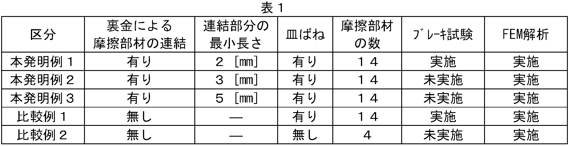
- the disc brake shown in FIG. 2 was adopted, and the analysis was performed for the three conditions of Examples 1 to 3 of the present invention.
- the plate thickness of the back metal was 2.3 mm
- the minimum width of the connection part of the back metal for connecting a pair of friction members was 21 mm.
- the minimum length of the connecting portion of the back metal that connects a pair of friction members was changed to 2 mm in Invention Example 1, 3 mm in Invention Example 2, and 5 mm in Invention Example 3.
- the longitudinal length of the substrate (the length corresponding to the circumferential direction of the brake disc) is 400 mm, and the length in the width direction (the length corresponding to the radial direction of the brake disc).
- the friction member was a copper sintered material, and all other materials were steel materials.
- the number of friction members was 14, and the planar shape was a circle with a diameter of 45 mm.
- the spring constant of the disc spring disposed between the friction member and the substrate was 7 kN / mm.
- the brake disk had a substantially disk shape with an inner diameter of 476 mm and an outer diameter of 724 mm, and the radial length of the sliding surface in contact with the brake lining was 120 mm.
- the FEM analysis was performed with a pressing force of 14 kN and a friction coefficient of the contact surface between the brake disc and the brake lining of 0.3.
- Comparative Example 1 among the various conditions of Example 1 of the present invention, a disc brake in which a backing metal is individually fixed to the back surface of each friction member without connecting a set of friction members with the backing metal (see Patent Document 1).
- Comparative Example 2 the conventional disc brake shown in FIG. 1 was used.
- the test was conducted under the two conditions of the present invention example 1 and the comparative example 1. In each test, eight different speeds were selected from 30 to 330 km / h as initial speeds, and emergency stop brakes were set from the initial speeds.
- An object of the present invention is to achieve both the above-described uniform contact area and stabilization of the friction coefficient, and further to ensure the durability of the disc brake.
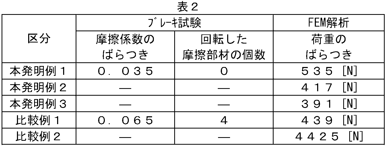
- the variation of the friction coefficient was investigated as an index corresponding to each, and whether or not each friction member was rotated on the spot was examined.
- the maximum value and the minimum value are extracted from the average friction coefficients obtained in the brake test from each initial speed, and the difference between them is defined as the variation in the friction coefficient.
- the variation of the load acting on each friction member was investigated as a corresponding index.
- the maximum value and the minimum value are extracted from among the loads acting on the friction members when the pressing force is applied, and the difference between them is defined as the variation in the load.
- Example 1 of the present invention a set of friction members are connected by a back metal, so that the variation in the friction coefficient is small and the rotation of the friction members does not occur. It can also be seen that the variation in load is reduced in Examples 1 to 3 of the present invention due to the effect of the elastic support of the friction member by the disc spring. From these facts, it becomes clear that the disc brake provided with the brake lining of the present invention can achieve both uniform contact area and stable friction coefficient, and can further ensure durability.
- Comparative Example 1 since a pair of friction members are not connected by a back metal, it can be seen that the variation in the coefficient of friction is relatively large and rotation is caused by a plurality of friction members. In Comparative Example 2, it can be seen that there is a large variation in load due to the conventional brake lining.
- the brake lining and disc brake for a railway vehicle of the present invention can be used effectively for any railway vehicle, and is particularly useful for a high-speed railway vehicle whose traveling speed is wide from low speed to high speed.
Abstract
Description
各々の表面がブレーキディスクの摺動面と対向し、各々が互いに隙間を隔てて配列された複数個の摩擦部材と、
各摩擦部材の裏面に固着された裏金と、
各摩擦部材をその中心部において裏面側からばね部材を介して支持し、ブレーキキャリパに取り付けられる基板と、からなり、
互いに隣接する2個の摩擦部材を一組とし、この一組の摩擦部材の裏金が一体であることを特徴とする鉄道車両用ブレーキライニングである。 (I) Brake lining pressed against a sliding surface of a brake disk fixed to a wheel or axle of a railway vehicle by a brake caliper,
A plurality of friction members, each surface facing the sliding surface of the brake disc, each arranged with a gap therebetween;
A backing metal fixed to the back surface of each friction member;
Each friction member is supported at the center by a spring member from the back side and is attached to a brake caliper.
A brake lining for a railway vehicle characterized in that two friction members adjacent to each other are taken as a set, and the back metal of the set of friction members is integrated.
上記のいずれかのブレーキライニングが取り付けられたブレーキキャリパと、を備えたことを特徴とする鉄道車両用ディスクブレーキである。 (II) a brake disc fixed to a wheel or axle of a railway vehicle;
And a brake caliper to which any one of the above brake linings is attached.
制動中のブレーキライニングとブレーキディスクの接触面圧の均一化を評価するため、FEM解析を行った。解析では、ブレーキライニングとブレーキディスクを弾性体でモデル化し、ブレーキライニングの背面からブレーキキャリパによる押付け力相当の荷重を与えた。このときに個々の摩擦部材に作用する荷重を評価した。 [Outline of analysis and test]
In order to evaluate the uniform contact pressure between the brake lining and the brake disc during braking, FEM analysis was performed. In the analysis, the brake lining and brake disc were modeled with elastic bodies, and a load equivalent to the pressing force by the brake caliper was applied from the back of the brake lining. At this time, the load acting on each friction member was evaluated.
FEM解析およびブレーキ試験の主要な実施条件を下記の表1にまとめて示す。 [Conditions]
The main conditions for FEM analysis and brake test are summarized in Table 1 below.
本発明の目的は、上記した接触面積の均一化と摩擦係数の安定化を両立し、さらにディスクブレーキの耐久性を確保することにある。ブレーキ試験では、摩擦係数の安定化と耐久性を評価するため、それぞれに対応する指標として、摩擦係数のばらつきを調査するとともに、個々の摩擦部材がその場で回転するか否かを調査した。ここでは、各初速度からのブレーキ試験で得られた平均摩擦係数の中で、最大値と最小値を抽出し、その差を摩擦係数のばらつきとした。 [Evaluation methods]
An object of the present invention is to achieve both the above-described uniform contact area and stabilization of the friction coefficient, and further to ensure the durability of the disc brake. In the brake test, in order to evaluate the stabilization and durability of the friction coefficient, the variation of the friction coefficient was investigated as an index corresponding to each, and whether or not each friction member was rotated on the spot was examined. Here, the maximum value and the minimum value are extracted from the average friction coefficients obtained in the brake test from each initial speed, and the difference between them is defined as the variation in the friction coefficient.
FEM解析およびブレーキ試験の結果を下記の表2にまとめて示す。 [result]
The results of FEM analysis and brake test are summarized in Table 2 below.
2:ブレーキライニング、 3:摩擦部材、 3a:小孔、
4:裏金、 4a:連結部分、 5:ばね部材、 6:基板、
7:リベット 1: brake disc, 1a: sliding surface,
2: brake lining, 3: friction member, 3a: small hole,
4: Back metal, 4a: Connection part, 5: Spring member, 6: Substrate,
7: Rivet
Claims (5)
- 鉄道車両の車輪または車軸に固定されたブレーキディスクの摺動面に、ブレーキキャリパによって押し付けられるブレーキライニングであって、
各々の表面がブレーキディスクの摺動面と対向し、各々が互いに隙間を隔てて配列された複数個の摩擦部材と、
各摩擦部材の裏面に固着された裏金と、
各摩擦部材をその中心部において裏面側からばね部材を介して支持し、ブレーキキャリパに取り付けられる基板と、からなり、
互いに隣接する2個の摩擦部材を一組とし、この一組の摩擦部材の裏金が一体であることを特徴とする鉄道車両用ブレーキライニング。 A brake lining that is pressed against a sliding surface of a brake disc fixed to a wheel or axle of a railway vehicle by a brake caliper,
A plurality of friction members, each surface facing the sliding surface of the brake disc, each arranged with a gap therebetween;
A backing metal fixed to the back surface of each friction member;
Each friction member is supported at the center by a spring member from the back side and is attached to a brake caliper.
A brake lining for a railway vehicle, characterized in that two friction members adjacent to each other are made into a set, and the back metal of the set of friction members is integrated. - 前記裏金は、当該裏金に固着された摩擦部材同士の隙間に相当する部分がくびれていることを特徴とする請求項1に記載の鉄道車両用ブレーキライニング。 2. The brake lining for a railway vehicle according to claim 1, wherein the back metal has a narrowed portion corresponding to a gap between friction members fixed to the back metal.
- 前記裏金のくびれ部の最小幅が、当該裏金に固着された摩擦部材の最大幅の1/3~2/3であることを特徴とする請求項2に記載の鉄道車両用ブレーキライニング。 3. The brake lining for a railway vehicle according to claim 2, wherein the minimum width of the constricted portion of the back metal is 1/3 to 2/3 of the maximum width of the friction member fixed to the back metal.
- 前記裏金は、当該裏金に固着された摩擦部材同士の隙間に相当する部分の最小長さが2~7mmであることを特徴とする請求項1~3のいずれかに記載の鉄道車両用ブレーキライニング。 The brake lining for a railway vehicle according to any one of claims 1 to 3, wherein the back metal has a minimum length of 2 to 7 mm corresponding to a gap between the friction members fixed to the back metal. .
- 鉄道車両の車輪または車軸に固定されたブレーキディスクと、
請求項1~4のいずれかに記載のブレーキライニングが取り付けられたブレーキキャリパと、を備えたことを特徴とする鉄道車両用ディスクブレーキ。 A brake disc fixed to a wheel or axle of a railway vehicle;
A disc brake for a railway vehicle, comprising: a brake caliper to which the brake lining according to any one of claims 1 to 4 is attached.
Priority Applications (6)
| Application Number | Priority Date | Filing Date | Title |
|---|---|---|---|
| ES12792495T ES2774259T3 (en) | 2011-06-02 | 2012-05-31 | Brake lining for railway vehicles and disc brakes equipped with the same |
| EP12792495.9A EP2716929B1 (en) | 2011-06-02 | 2012-05-31 | Brake lining for railway vehicles and disc brakes equipped with the same |
| KR1020137034153A KR101526784B1 (en) | 2011-06-02 | 2012-05-31 | Brake lining for railway vehicles and disc brakes equipped with same |
| CN201280026821.1A CN103562587B (en) | 2011-06-02 | 2012-05-31 | Brake lining for railway vehicles and disc brakes equipped with same |
| US14/123,260 US9394953B2 (en) | 2011-06-02 | 2012-05-31 | Brake lining for railway vehicles and disc brake equipped with the same |
| BR112013030757A BR112013030757A2 (en) | 2011-06-02 | 2012-05-31 | brake lining for rail and disc brake vehicles fitted with the same |
Applications Claiming Priority (2)
| Application Number | Priority Date | Filing Date | Title |
|---|---|---|---|
| JP2011-124145 | 2011-06-02 | ||
| JP2011124145A JP5706237B2 (en) | 2011-06-02 | 2011-06-02 | Railway vehicle brake lining and disc brake equipped with the same |
Publications (1)
| Publication Number | Publication Date |
|---|---|
| WO2012164935A1 true WO2012164935A1 (en) | 2012-12-06 |
Family
ID=47258807
Family Applications (1)
| Application Number | Title | Priority Date | Filing Date |
|---|---|---|---|
| PCT/JP2012/003568 WO2012164935A1 (en) | 2011-06-02 | 2012-05-31 | Brake lining for railway vehicles and disc brakes equipped with same |
Country Status (9)
| Country | Link |
|---|---|
| US (1) | US9394953B2 (en) |
| EP (1) | EP2716929B1 (en) |
| JP (1) | JP5706237B2 (en) |
| KR (1) | KR101526784B1 (en) |
| CN (1) | CN103562587B (en) |
| BR (1) | BR112013030757A2 (en) |
| ES (1) | ES2774259T3 (en) |
| TW (1) | TWI621557B (en) |
| WO (1) | WO2012164935A1 (en) |
Cited By (2)
| Publication number | Priority date | Publication date | Assignee | Title |
|---|---|---|---|---|
| JP2018517108A (en) * | 2015-06-09 | 2018-06-28 | フェデラル−モーグル ブレムスベラーク ゲーエムベーハー | Elastic installation of friction lining elements in the brake lining |
| CN108431443A (en) * | 2015-12-25 | 2018-08-21 | 新日铁住金株式会社 | Rail truck brake lining and the disk brake for having the rail truck brake lining |
Families Citing this family (21)
| Publication number | Priority date | Publication date | Assignee | Title |
|---|---|---|---|---|
| JP6041746B2 (en) * | 2013-04-18 | 2016-12-14 | 曙ブレーキ工業株式会社 | Friction pad assembly for disc brake |
| KR101499776B1 (en) * | 2013-10-11 | 2015-03-09 | 한국철도기술연구원 | Disc Brake For Vehicle |
| CN105705820A (en) * | 2013-11-05 | 2016-06-22 | 三菱电机株式会社 | Brake device |
| KR101940834B1 (en) * | 2014-04-14 | 2019-01-22 | 건국대학교 산학협력단 | Brake hils system for a railway vehicle |
| DE102014113058A1 (en) * | 2014-09-10 | 2016-03-10 | Federal-Mogul Bremsbelag Gmbh | Connection of a friction lining on a carrier plate of a brake pad |
| DE202014104703U1 (en) * | 2014-09-30 | 2016-01-07 | Špaček Stanislav | Brake pad and its components |
| CN104500628B (en) * | 2014-12-17 | 2018-03-27 | 北京天宜上佳新材料股份有限公司 | A kind of brake pad |
| KR102535994B1 (en) * | 2015-02-18 | 2023-05-24 | 코프렌 에스.알.엘. | Pad for disc brakes for railway vehicles |
| JP1547756S (en) * | 2015-10-21 | 2016-04-11 | ||
| WO2017069140A1 (en) * | 2015-10-21 | 2017-04-27 | 新日鐵住金株式会社 | Brake lining for railroad vehicle and disk brake provided with same |
| DE102015118783B4 (en) | 2015-11-03 | 2019-10-24 | Saf-Holland Gmbh | brake shoe |
| US11434964B2 (en) | 2015-12-28 | 2022-09-06 | Nippon Steel Corporation | Brake lining for a railway vehicle and disk brake equipped with the same |
| DE102016100454A1 (en) * | 2016-01-13 | 2017-07-13 | Knorr-Bremse Systeme für Schienenfahrzeuge GmbH | Brake pad for disc brakes of rail vehicles |
| US20190078629A1 (en) * | 2016-03-17 | 2019-03-14 | Nippon Steel & Sumitomo Metal Corporation | Brake lining for railway vehicle and disk brake for railway vehicle including the same |
| WO2017196978A1 (en) * | 2016-05-10 | 2017-11-16 | Hyperloop Technologies, Inc. | Friction braking system |
| CN205806293U (en) * | 2016-06-30 | 2016-12-14 | 北京北摩高科摩擦材料有限责任公司 | A kind of train elastic adjusting type brake pad |
| BR112019011911A2 (en) * | 2016-12-27 | 2019-11-05 | Nippon Steel Corp | disc braking device |
| TWI696773B (en) * | 2017-12-15 | 2020-06-21 | 日商日本製鐵股份有限公司 | Brake order for railway vehicles, disc brake system for railway vehicles using the brakes for railway vehicles, and sintered friction materials used for braking for railway vehicles |
| IT201800010235A1 (en) * | 2018-11-12 | 2020-05-12 | Cofren Srl | PAD WITH VARIABLE FLEXIBILITY NUTS FOR DISC BRAKES FOR RAILWAY VEHICLES |
| IT201900006094A1 (en) * | 2019-04-18 | 2020-10-18 | Cofren Srl | PAD FOR DISC BRAKES FOR RAILWAY VEHICLES |
| KR102448524B1 (en) * | 2020-05-26 | 2022-09-29 | (주)베스트카본 | Brake pad for ship oil pump using simultaneous sintering process and method of manufacuring thereof |
Citations (5)
| Publication number | Priority date | Publication date | Assignee | Title |
|---|---|---|---|---|
| JPS4634271Y1 (en) * | 1966-11-21 | 1971-11-26 | ||
| JPH10507250A (en) * | 1994-10-12 | 1998-07-14 | クノル−ブレムゼ ジステーメ フューア シーネンファールツォイゲ ゲゼルシャフト ミット ベシュレンクテル ハフツング | Partial linings, especially for railway vehicles-brake linings for disc brakes |
| WO2002073059A1 (en) | 2001-03-13 | 2002-09-19 | Federal-Mogul Friction Products Limited | Friction pad |
| JP2006194429A (en) | 2005-01-10 | 2006-07-27 | Cofren Srl | Improvement of disc brake pad comprising frictional element mainly used in field of railroad |
| JP2008151188A (en) | 2006-12-14 | 2008-07-03 | Sumitomo Metal Ind Ltd | Brake lining and disk brake for railroad vehicle |
Family Cites Families (20)
| Publication number | Priority date | Publication date | Assignee | Title |
|---|---|---|---|---|
| US2129372A (en) * | 1935-02-15 | 1938-09-06 | Borg Warner | Clutch plate |
| US2986252A (en) * | 1957-10-02 | 1961-05-30 | Bendix Corp | Mounting for friction lining segments |
| US3297117A (en) * | 1965-04-30 | 1967-01-10 | Budd Co | Conformable rotary disk brake shoe assembly |
| GB1400408A (en) * | 1971-06-22 | 1975-07-16 | Bba Group Ltd | Friction clutch devices and components therefor |
| FR2663701B1 (en) * | 1990-06-22 | 1992-11-27 | Valeo | FRICTION DISC, ESPECIALLY FOR CLUTCH. |
| JPH0634271Y2 (en) * | 1990-07-11 | 1994-09-07 | 栄和産業株式会社 | Accessory box |
| IT1261780B (en) * | 1993-04-05 | 1996-06-03 | DISC BRAKE PAD WITH SINTERED FRICTION ELEMENTS. | |
| DK1099061T3 (en) * | 1998-07-25 | 2003-03-10 | Tmd Friction Esco Gmbh | Disc brake linings for rail vehicles or commercial and public vehicles |
| DE29821113U1 (en) | 1998-11-25 | 1999-02-18 | Jurid Werke Gmbh | Brake pad |
| JP2006275230A (en) * | 2005-03-30 | 2006-10-12 | Sumitomo Metal Ind Ltd | Brake lining and disc brake for railroad vehicle |
| JP4006450B2 (en) * | 2005-04-26 | 2007-11-14 | 曙ブレーキ工業株式会社 | Friction material assembly for disc brake |
| GB0523858D0 (en) * | 2005-11-24 | 2006-01-04 | Federal Mogul Friction Product | Pad assembly for use in a disc brake |
| US7593796B2 (en) * | 2006-11-27 | 2009-09-22 | Toyota Motor Engineering & Manufacturing North America, Inc. | Torque estimator for internal combustion engine |
| EP2088050B1 (en) * | 2008-02-07 | 2016-10-05 | Akebono Brake Industry Co., Ltd. | Disc brake friction member assembly |
| AT508297B1 (en) * | 2009-05-29 | 2012-02-15 | Miba Frictec Gmbh | friction |
| KR20110024257A (en) * | 2009-09-01 | 2011-03-09 | 주식회사 다윈프릭션 | Friction pad for brake system |
| IT1396994B1 (en) * | 2009-11-05 | 2012-12-20 | Cofren Srl | IMPROVED SHOE FOR DISC BRAKES FOR RAILWAY AND INDUSTRIAL VEHICLES. |
| CN201714879U (en) * | 2010-01-14 | 2011-01-19 | 贵州新安航空机械有限责任公司 | Elastic brake pad with riveted structure |
| CN201606435U (en) * | 2010-01-14 | 2010-10-13 | 贵州新安航空机械有限责任公司 | Brake pad with elastic floating structure |
| DE102010019765A1 (en) * | 2010-05-07 | 2011-11-10 | Knorr-Bremse Systeme für Schienenfahrzeuge GmbH | Brake lining for a partially coated disc brake |
-
2011
- 2011-06-02 JP JP2011124145A patent/JP5706237B2/en active Active
-
2012
- 2012-05-31 CN CN201280026821.1A patent/CN103562587B/en active Active
- 2012-05-31 WO PCT/JP2012/003568 patent/WO2012164935A1/en active Application Filing
- 2012-05-31 EP EP12792495.9A patent/EP2716929B1/en active Active
- 2012-05-31 BR BR112013030757A patent/BR112013030757A2/en not_active Application Discontinuation
- 2012-05-31 ES ES12792495T patent/ES2774259T3/en active Active
- 2012-05-31 KR KR1020137034153A patent/KR101526784B1/en active IP Right Grant
- 2012-05-31 US US14/123,260 patent/US9394953B2/en active Active
- 2012-06-01 TW TW101119757A patent/TWI621557B/en active
Patent Citations (5)
| Publication number | Priority date | Publication date | Assignee | Title |
|---|---|---|---|---|
| JPS4634271Y1 (en) * | 1966-11-21 | 1971-11-26 | ||
| JPH10507250A (en) * | 1994-10-12 | 1998-07-14 | クノル−ブレムゼ ジステーメ フューア シーネンファールツォイゲ ゲゼルシャフト ミット ベシュレンクテル ハフツング | Partial linings, especially for railway vehicles-brake linings for disc brakes |
| WO2002073059A1 (en) | 2001-03-13 | 2002-09-19 | Federal-Mogul Friction Products Limited | Friction pad |
| JP2006194429A (en) | 2005-01-10 | 2006-07-27 | Cofren Srl | Improvement of disc brake pad comprising frictional element mainly used in field of railroad |
| JP2008151188A (en) | 2006-12-14 | 2008-07-03 | Sumitomo Metal Ind Ltd | Brake lining and disk brake for railroad vehicle |
Non-Patent Citations (1)
| Title |
|---|
| See also references of EP2716929A4 * |
Cited By (3)
| Publication number | Priority date | Publication date | Assignee | Title |
|---|---|---|---|---|
| JP2018517108A (en) * | 2015-06-09 | 2018-06-28 | フェデラル−モーグル ブレムスベラーク ゲーエムベーハー | Elastic installation of friction lining elements in the brake lining |
| CN108431443A (en) * | 2015-12-25 | 2018-08-21 | 新日铁住金株式会社 | Rail truck brake lining and the disk brake for having the rail truck brake lining |
| CN108431443B (en) * | 2015-12-25 | 2020-03-17 | 日本制铁株式会社 | Brake lining for railway vehicle and disc brake provided with same |
Also Published As
| Publication number | Publication date |
|---|---|
| ES2774259T3 (en) | 2020-07-20 |
| US20140097049A1 (en) | 2014-04-10 |
| EP2716929A4 (en) | 2016-01-13 |
| BR112013030757A2 (en) | 2016-12-06 |
| US9394953B2 (en) | 2016-07-19 |
| CN103562587B (en) | 2017-02-15 |
| KR101526784B1 (en) | 2015-06-05 |
| TWI621557B (en) | 2018-04-21 |
| TW201309520A (en) | 2013-03-01 |
| KR20140013094A (en) | 2014-02-04 |
| EP2716929B1 (en) | 2020-01-01 |
| CN103562587A (en) | 2014-02-05 |
| JP5706237B2 (en) | 2015-04-22 |
| JP2012251597A (en) | 2012-12-20 |
| EP2716929A1 (en) | 2014-04-09 |
Similar Documents
| Publication | Publication Date | Title |
|---|---|---|
| JP5706237B2 (en) | Railway vehicle brake lining and disc brake equipped with the same | |
| JP5512337B2 (en) | Brake lining for railway vehicles | |
| CN108474425B (en) | Brake friction lining for railway vehicle and disc brake for railway vehicle using the same | |
| JP6567084B2 (en) | Railway vehicle brake lining and disc brake equipped with the same | |
| WO2013121731A1 (en) | Brake lining for railway vehicle, and disc brake with same | |
| TWI621789B (en) | Brake pad for railway vehicle, and disc brake for railway vehicle using the same | |
| TWI614423B (en) | Brake trucks for railway vehicles and disc brakes with the brakes | |
| JP6773670B2 (en) | Brake linings for rail vehicles and disc brakes with them | |
| JP2006275230A (en) | Brake lining and disc brake for railroad vehicle | |
| JP2020076470A (en) | Brake lining for railway vehicle and disc brake for railway vehicle |
Legal Events
| Date | Code | Title | Description |
|---|---|---|---|
| 121 | Ep: the epo has been informed by wipo that ep was designated in this application |
Ref document number: 12792495 Country of ref document: EP Kind code of ref document: A1 |
|
| NENP | Non-entry into the national phase |
Ref country code: DE |
|
| WWE | Wipo information: entry into national phase |
Ref document number: 14123260 Country of ref document: US |
|
| ENP | Entry into the national phase |
Ref document number: 20137034153 Country of ref document: KR Kind code of ref document: A |
|
| REG | Reference to national code |
Ref country code: BR Ref legal event code: B01A Ref document number: 112013030757 Country of ref document: BR |
|
| ENP | Entry into the national phase |
Ref document number: 112013030757 Country of ref document: BR Kind code of ref document: A2 Effective date: 20131129 |