WO2012164748A1 - 内燃機関の排気浄化装置 - Google Patents
内燃機関の排気浄化装置 Download PDFInfo
- Publication number
- WO2012164748A1 WO2012164748A1 PCT/JP2011/062833 JP2011062833W WO2012164748A1 WO 2012164748 A1 WO2012164748 A1 WO 2012164748A1 JP 2011062833 W JP2011062833 W JP 2011062833W WO 2012164748 A1 WO2012164748 A1 WO 2012164748A1
- Authority
- WO
- WIPO (PCT)
- Prior art keywords
- exhaust
- additive
- internal combustion
- combustion engine
- exhaust passage
- Prior art date
- Legal status (The legal status is an assumption and is not a legal conclusion. Google has not performed a legal analysis and makes no representation as to the accuracy of the status listed.)
- Ceased
Links
Images


Classifications
-
- B—PERFORMING OPERATIONS; TRANSPORTING
- B01—PHYSICAL OR CHEMICAL PROCESSES OR APPARATUS IN GENERAL
- B01F—MIXING, e.g. DISSOLVING, EMULSIFYING OR DISPERSING
- B01F25/00—Flow mixers; Mixers for falling materials, e.g. solid particles
- B01F25/40—Static mixers
- B01F25/42—Static mixers in which the mixing is affected by moving the components jointly in changing directions, e.g. in tubes provided with baffles or obstructions
- B01F25/43—Mixing tubes, e.g. wherein the material is moved in a radial or partly reversed direction
- B01F25/431—Straight mixing tubes with baffles or obstructions that do not cause substantial pressure drop; Baffles therefor
- B01F25/4316—Straight mixing tubes with baffles or obstructions that do not cause substantial pressure drop; Baffles therefor the baffles being flat pieces of material, e.g. intermeshing, fixed to the wall or fixed on a central rod
-
- F—MECHANICAL ENGINEERING; LIGHTING; HEATING; WEAPONS; BLASTING
- F01—MACHINES OR ENGINES IN GENERAL; ENGINE PLANTS IN GENERAL; STEAM ENGINES
- F01N—GAS-FLOW SILENCERS OR EXHAUST APPARATUS FOR MACHINES OR ENGINES IN GENERAL; GAS-FLOW SILENCERS OR EXHAUST APPARATUS FOR INTERNAL-COMBUSTION ENGINES
- F01N3/00—Exhaust or silencing apparatus having means for purifying, rendering innocuous, or otherwise treating exhaust
- F01N3/08—Exhaust or silencing apparatus having means for purifying, rendering innocuous, or otherwise treating exhaust for rendering innocuous
- F01N3/10—Exhaust or silencing apparatus having means for purifying, rendering innocuous, or otherwise treating exhaust for rendering innocuous by thermal or catalytic conversion of noxious components of exhaust
- F01N3/24—Exhaust or silencing apparatus having means for purifying, rendering innocuous, or otherwise treating exhaust for rendering innocuous by thermal or catalytic conversion of noxious components of exhaust characterised by constructional aspects of converting apparatus
- F01N3/28—Construction of catalytic reactors
- F01N3/2892—Exhaust flow directors or the like, e.g. upstream of catalytic device
-
- B—PERFORMING OPERATIONS; TRANSPORTING
- B01—PHYSICAL OR CHEMICAL PROCESSES OR APPARATUS IN GENERAL
- B01F—MIXING, e.g. DISSOLVING, EMULSIFYING OR DISPERSING
- B01F23/00—Mixing according to the phases to be mixed, e.g. dispersing or emulsifying
- B01F23/20—Mixing gases with liquids
- B01F23/21—Mixing gases with liquids by introducing liquids into gaseous media
- B01F23/213—Mixing gases with liquids by introducing liquids into gaseous media by spraying or atomising of the liquids
- B01F23/2132—Mixing gases with liquids by introducing liquids into gaseous media by spraying or atomising of the liquids using nozzles
-
- B—PERFORMING OPERATIONS; TRANSPORTING
- B01—PHYSICAL OR CHEMICAL PROCESSES OR APPARATUS IN GENERAL
- B01F—MIXING, e.g. DISSOLVING, EMULSIFYING OR DISPERSING
- B01F25/00—Flow mixers; Mixers for falling materials, e.g. solid particles
- B01F25/30—Injector mixers
- B01F25/31—Injector mixers in conduits or tubes through which the main component flows
- B01F25/313—Injector mixers in conduits or tubes through which the main component flows wherein additional components are introduced in the centre of the conduit
- B01F25/3131—Injector mixers in conduits or tubes through which the main component flows wherein additional components are introduced in the centre of the conduit with additional mixing means other than injector mixers, e.g. screens, baffles or rotating elements
-
- B—PERFORMING OPERATIONS; TRANSPORTING
- B01—PHYSICAL OR CHEMICAL PROCESSES OR APPARATUS IN GENERAL
- B01F—MIXING, e.g. DISSOLVING, EMULSIFYING OR DISPERSING
- B01F25/00—Flow mixers; Mixers for falling materials, e.g. solid particles
- B01F25/40—Static mixers
- B01F25/42—Static mixers in which the mixing is affected by moving the components jointly in changing directions, e.g. in tubes provided with baffles or obstructions
- B01F25/43—Mixing tubes, e.g. wherein the material is moved in a radial or partly reversed direction
- B01F25/431—Straight mixing tubes with baffles or obstructions that do not cause substantial pressure drop; Baffles therefor
- B01F25/43197—Straight mixing tubes with baffles or obstructions that do not cause substantial pressure drop; Baffles therefor characterised by the mounting of the baffles or obstructions
- B01F25/431974—Support members, e.g. tubular collars, with projecting baffles fitted inside the mixing tube or adjacent to the inner wall
-
- B—PERFORMING OPERATIONS; TRANSPORTING
- B01—PHYSICAL OR CHEMICAL PROCESSES OR APPARATUS IN GENERAL
- B01F—MIXING, e.g. DISSOLVING, EMULSIFYING OR DISPERSING
- B01F25/00—Flow mixers; Mixers for falling materials, e.g. solid particles
- B01F25/20—Jet mixers, i.e. mixers using high-speed fluid streams
- B01F25/25—Mixing by jets impinging against collision plates
-
- F—MECHANICAL ENGINEERING; LIGHTING; HEATING; WEAPONS; BLASTING
- F01—MACHINES OR ENGINES IN GENERAL; ENGINE PLANTS IN GENERAL; STEAM ENGINES
- F01N—GAS-FLOW SILENCERS OR EXHAUST APPARATUS FOR MACHINES OR ENGINES IN GENERAL; GAS-FLOW SILENCERS OR EXHAUST APPARATUS FOR INTERNAL-COMBUSTION ENGINES
- F01N2240/00—Combination or association of two or more different exhaust treating devices, or of at least one such device with an auxiliary device, not covered by indexing codes F01N2230/00 or F01N2250/00, one of the devices being
- F01N2240/20—Combination or association of two or more different exhaust treating devices, or of at least one such device with an auxiliary device, not covered by indexing codes F01N2230/00 or F01N2250/00, one of the devices being a flow director or deflector
-
- F—MECHANICAL ENGINEERING; LIGHTING; HEATING; WEAPONS; BLASTING
- F01—MACHINES OR ENGINES IN GENERAL; ENGINE PLANTS IN GENERAL; STEAM ENGINES
- F01N—GAS-FLOW SILENCERS OR EXHAUST APPARATUS FOR MACHINES OR ENGINES IN GENERAL; GAS-FLOW SILENCERS OR EXHAUST APPARATUS FOR INTERNAL-COMBUSTION ENGINES
- F01N2610/00—Adding substances to exhaust gases
Definitions
- the present invention relates to an exhaust purification device for an internal combustion engine.
- a technology that includes a dispersion plate for dispersing urea water between the selective reduction type NOx catalyst and the injection valve It is known (for example, refer to Patent Document 1). Since the exhaust plate and the urea water are swirled by the dispersion plate, mixing and vaporization of the urea water and the exhaust gas are promoted.
- a technique in which a dispersion plate is provided on the downstream side of the injection nozzle for injecting urea water (for example, see Patent Document 2).
- the dispersion plate is provided so as to be orthogonal to the flow direction of the exhaust gas. Further, the dispersion plate is provided with a plurality of collision pieces obtained by cutting a part of the surface of the dispersion plate and bending it in the downstream direction.
- the reflected additive may be directed to the wall surface of the exhaust passage. If the additive adheres to the wall surface of the exhaust pipe, precipitates derived from urea may be deposited on the wall surface of the exhaust pipe. Further, since the urea water reaching the selective reduction type NOx catalyst is reduced by the amount adhering to the wall surface of the exhaust pipe, there is a possibility that the NOx purification rate is lowered due to the lack of urea water in the selective reduction type NOx catalyst. Further, the gas density may be higher on the wall surface side than on the central axis side of the exhaust passage. If it does so, there exists a possibility that the gas amount and additive amount which are supplied to the center axis
- An object of the present invention is to suppress the bias of the additive supplied into the exhaust gas from the internal combustion engine and to disperse the additive more uniformly.
- an exhaust gas purification apparatus for an internal combustion engine comprises: An exhaust purification catalyst provided in the exhaust passage of the internal combustion engine; A supply unit that is provided in an exhaust passage upstream of the exhaust purification catalyst and supplies an additive to the exhaust purification catalyst; A dispersion part that is provided between the exhaust purification catalyst and the supply part and disperses the additive; An exhaust gas purification apparatus for an internal combustion engine comprising: The dispersion portion includes blades extending from the wall surface side of the exhaust passage to the central axis side of the exhaust passage and to the downstream side in the exhaust flow direction.
- the additive collides with the blades of the dispersion unit.
- the blades extend from the wall surface side of the exhaust passage to the central axis side of the exhaust passage and to the downstream side in the exhaust flow direction. That is, the blade extending from the wall surface of the exhaust passage is located on the downstream side of the exhaust toward the tip end side. This can be said that the blades are inclined toward the downstream side of the exhaust.
- the additive colliding with the blade is easily reflected in the direction of the central axis of the exhaust passage. That is, it can suppress that an additive reflects on the wall surface side of an exhaust passage. Thereby, it can suppress that an additive is biased to the wall surface vicinity of an exhaust passage. Similarly, the exhaust can be suppressed from being biased to the vicinity of the wall surface of the exhaust passage.
- the blade is provided so that the traveling direction after the additive supplied from the supply unit collides with the blade is directed to the central axis side rather than the wall surface side of the exhaust passage. May be.
- the blades so that the angle between the traveling direction of the additive supplied from the supply unit and the direction in which the blades extend from the wall surface side of the exhaust passage is an acute angle, the additive colliding with the blades is Reflected in the direction of the central axis of the exhaust passage, not in the direction of the wall surface of the exhaust passage. For this reason, it can suppress more that an additive is biased to the wall surface vicinity of an exhaust passage.
- the exhaust purification catalyst may be a selective reduction type NOx catalyst, and the additive may be urea water.
- the NOx purification rate can be improved.
- FIG. 1 is a diagram showing a schematic configuration of an exhaust gas purification apparatus for an internal combustion engine according to the present embodiment.
- the internal combustion engine 1 shown in FIG. 1 may be a diesel engine or a gasoline engine.
- the exhaust passage 2 is connected to the internal combustion engine 1.
- An exhaust purification catalyst 3 (hereinafter simply referred to as “catalyst 3”) is provided in the middle of the exhaust passage 2.
- the catalyst 3 is a catalyst whose temperature rises, exhaust gas is purified, or purification ability is restored by supplying an additive.
- the catalyst 3 include an occlusion reduction type NOx catalyst, a selective reduction type NOx catalyst, a three-way catalyst, an oxidation catalyst, and a hydrolysis catalyst.
- the selective reduction type NOx catalyst may be a catalyst that purifies NOx by supplying urea water as an additive.
- the catalyst 3 may be a catalyst having an oxidation function.
- a particulate filter that collects particulate matter may be provided, and the particulate filter may be used as the carrier of the catalyst 3. Moreover, you may arrange
- an injection valve 4 for injecting the additive into the exhaust is provided in the exhaust passage 2 upstream of the catalyst 3.
- the central axis of the injection valve 4 is provided on the extension line of the central axis Z of the exhaust passage on the downstream side of the injection valve 4, and the injection hole thereof faces the downstream side of the exhaust passage 2. For this reason, the center of mass of the additive injected from the injection valve 4 advances on the central axis Z of the exhaust passage 2.
- the additive can be, for example, a reducing agent or an oxidizing agent. Further, for example, fuel, urea water, or ammonia can be used as the additive. What is used as the additive depends on the type of the catalyst 3.
- the injection valve 4 corresponds to the supply unit in the present invention.
- a disperser 5 for dispersing the additive in the exhaust gas is provided in the exhaust passage downstream of the injection valve 4 and upstream of the catalyst 3.
- the disperser 5 corresponds to the disperser in the present invention.
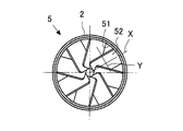
- FIG. 2 is a view of the disperser 5 viewed from the upstream side in the exhaust flow direction.
- FIG. 3 is a cross-sectional view of the disperser 5 cut in parallel with the exhaust flow direction.
- the disperser 5 includes a cylindrical portion 51 that has an outer diameter substantially equal to the inner diameter of the exhaust passage 2 and is formed in a hollow cylindrical shape coaxial with the central axis Z of the exhaust passage 2. .
- a plurality of blades 52 having the same shape extend from the inner peripheral surface of the cylindrical portion 51 toward the central axis Z side of the exhaust passage 2 and toward the downstream side in the exhaust flow direction. That is, the blades 52 extend from the wall surface side of the exhaust passage 2 toward the central axis Z side of the exhaust passage 2 and toward the downstream side in the exhaust flow direction.
- the plurality of blades 52 are arranged radially at equal angles around the central axis of the cylindrical portion 51. In this way, each blade 52 is bent downstream at the base.
- a line connecting the center of the base of the blade 52 and the center of the tip of the blade 52 is defined as a central axis X in the long side direction of the blade 52.
- the central axis X in the long side direction is the central axis in the direction in which the blades 52 extend, and is the central axis in the length direction of the blades 52.
- the center of the base of the blade is the midpoint of the side formed by the intersection of the blade 52 and the cylindrical portion 51.
- the center of the tip of the blade 52 is the midpoint of the side facing the root of the blade 52.
- the central axis X in the long side direction faces the central axis Z side of the exhaust passage 2 and the downstream side in the exhaust flow direction.
- the tip of the blade 52 does not have to be configured with a straight line. For example, it may be a curve. Further, the tip of the blade 52 may be sharp.
- a line connecting the midpoints of the two long sides from the root of the blade 52 to the tip is defined as a central axis Y in the short side direction of the blade 52.
- the blades 52 are formed so that the central axis Y in the short side direction is not orthogonal to the central axis Z of the exhaust passage 2 and has a predetermined angle. Both the central axis X in the long side direction and the central axis Y in the short side direction are not orthogonal to the central axis Z of the exhaust passage 2.
- wing 52 is provided so that it may not contact
- the exhaust gas turns around the central axis of the cylindrical portion 51.
- the dispersion device 5 configured as described above, when the exhaust gas and the additive pass through the dispersion device 5, the flow direction of the exhaust gas is changed by the plurality of blades 52, and the exhaust gas turns around the central axis Z of the exhaust passage 2. To do. Then, when the additive is supplied toward the disperser 5, the additive and the exhaust gas are swirled so that the additive is dispersed in the exhaust gas.
- the blade 52 is provided so that the traveling direction after the additive injected from the injection valve 4 collides with the blade 52 is directed to the central axis Z side rather than the wall surface side of the exhaust passage 2. Yes. That is, the blade 52 is formed so that an angle B formed by the traveling direction of the outer peripheral portion A of the additive spray and the central axis X of the long side direction of the blade 52 extending from the tube portion 51 to the tip of the blade 52 is an acute angle. The tilt angle is set. Thereby, the additive which collided with the blade
- the exhaust gas can be prevented from moving toward the wall surface of the exhaust passage 2 after colliding with the blade 52. Accordingly, since it is possible to suppress the additive and the exhaust from being biased to the vicinity of the wall surface of the exhaust passage 2, the exhaust and the additive flowing into the catalyst 3 become more uniform. That is, an appropriate amount of additive can be supplied also near the central axis of the catalyst 3. Further, the gas density near the central axis of the catalyst 3 can be improved to an appropriate value. As a result, the exhaust purification performance can be improved.
- the exhaust and additive are provided by providing the blade 52 extending from the wall surface side of the exhaust passage 2 to the central axis Z side of the exhaust passage 2 and downstream in the exhaust flow direction. Can be prevented from being biased toward the wall surface side of the exhaust passage 2. Further, since the vane 52 is provided so that the traveling direction after the additive collides with the vane 52 is directed to the central axis Z side rather than the wall surface side of the exhaust passage 2, the exhaust gas and the additive are supplied to the wall surface of the exhaust passage 2. It can suppress more biasing to the side.
- the additive can be dispersed over a short distance, the distance between the disperser 5 and the catalyst 3 can be reduced. Therefore, it is easier to install the disperser 5 than in the prior art.
Landscapes
- Chemical & Material Sciences (AREA)
- Chemical Kinetics & Catalysis (AREA)
- Engineering & Computer Science (AREA)
- Dispersion Chemistry (AREA)
- Health & Medical Sciences (AREA)
- Toxicology (AREA)
- Combustion & Propulsion (AREA)
- Mechanical Engineering (AREA)
- General Engineering & Computer Science (AREA)
- Exhaust Gas After Treatment (AREA)
Abstract
内燃機関からの排気中に供給される添加剤の偏りを抑制して、添加剤をより均一に分散させることを目的とする。内燃機関の排気通路(2)に設けられる排気浄化触媒と、排気浄化触媒よりも上流の排気通路に設けられ排気浄化触媒へ添加剤を供給する供給部(4)と、排気浄化触媒と供給部(4)との間に設けられ添加剤を分散させる分散部(5)と、を備える内燃機関の排気浄化装置において、分散部(5)は、排気通路(2)の壁面から、排気通路(2)の中心軸側で且つ排気の流れ方向の下流側へ延びる羽根(52)を備える。
Description
本発明は、内燃機関の排気浄化装置に関する。
選択還元型NOx触媒と、尿素水を噴射する噴射弁と、を備えたSCRシステムにおいて、選択還元型NOx触媒と、噴射弁との間に、尿素水を分散させるための分散板を備える技術が知られている(例えば、特許文献1参照。)。この分散板により排気及び尿素水が旋回するため、尿素水と排気との混合及び気化が促進される。
また、尿素水を噴射する噴射ノズルよりも下流側に分散板を設ける技術が知られている(例えば、特許文献2参照。)。この分散板は、排気の流れ方向に対して直交するように設けられる。また、分散板には、該分散板の表面の一部を切って下流方向に折り曲げた衝突片が複数備わる。
また、排気通路に接続される噴射通路内に噴射弁を備え、噴射通路の噴射弁側にガスを流入可能な通路を備える技術が知られている(例えば、特許文献3参照。)。この技術では、噴射通路内の気圧の低下を抑制して噴霧の形状を維持するにより、該噴射通路の壁面に添加剤が付着することを抑制している。
ところで、添加剤が分散板に衝突すると、反射した添加剤が排気通路の壁面に向かう虞がある。そして、添加剤が排気管の壁面に付着すると、排気管の壁面に尿素由来の析出物が堆積する虞がある。また、排気管の壁面に付着した分だけ選択還元型NOx触媒へ到達する尿素水が減少するため、選択還元型NOx触媒において尿素水の不足によりNOxの浄化率が低下する虞がある。また、ガスの密度が排気通路の中心軸側よりも壁面側で高くなる虞がある。そうすると、触媒の中心軸側に供給されるガス量や添加剤量が不足する虞がある。
本発明は、内燃機関からの排気中に供給される添加剤の偏りを抑制して、添加剤をより均一に分散させることを目的とする。
上記課題を達成するために本発明による内燃機関の排気浄化装置は、
内燃機関の排気通路に設けられる排気浄化触媒と、
前記排気浄化触媒よりも上流の排気通路に設けられ、前記排気浄化触媒へ添加剤を供給する供給部と、
前記排気浄化触媒と前記供給部との間に設けられ、前記添加剤を分散させる分散部と、
を備える内燃機関の排気浄化装置において、
前記分散部は、排気通路の壁面側から、排気通路の中心軸側で且つ排気の流れ方向の下流側へ延びる羽根を備える。
内燃機関の排気通路に設けられる排気浄化触媒と、
前記排気浄化触媒よりも上流の排気通路に設けられ、前記排気浄化触媒へ添加剤を供給する供給部と、
前記排気浄化触媒と前記供給部との間に設けられ、前記添加剤を分散させる分散部と、
を備える内燃機関の排気浄化装置において、
前記分散部は、排気通路の壁面側から、排気通路の中心軸側で且つ排気の流れ方向の下流側へ延びる羽根を備える。
ここで、供給部より添加剤が供給されると、添加剤は分散部の羽根に衝突する。ここで、羽根は、排気通路の壁面側から、排気通路の中心軸側で且つ排気の流れ方向の下流側へ延びている。すなわち、排気通路の壁面から延びている羽根は、先端部側ほど排気の下流側に位置する。これは、羽根は排気の下流側に向けて傾斜しているともいえる。このため、羽根に衝突した添加剤が、排気通路の中心軸方向に反射し易くなる。すなわち、添加剤が排気通路の壁面側に反射することを抑制できる。これにより、添加剤が排気通路の壁面付近に偏ることを抑制できる。また、排気についても同様に、排気通路の壁面付近に偏ることを抑制できる。
また、本発明においては、前記供給部から供給される添加剤が前記羽根に衝突した後の進行方向を、前記排気通路の壁面側よりも中心軸側へ向けるように、前記羽根が設けられていてもよい。
ここで、供給部から供給される添加剤の進行方向と、排気通路の壁面側から羽根が延びる方向と、の角度が鋭角となるように、羽根を設けることにより、羽根に衝突した添加剤は排気通路の壁面方向ではなく排気通路の中心軸方向に反射する。このため、添加剤が排気通路の壁面付近に偏ることを、より抑制できる。
なお、本発明においては、前記排気浄化触媒は、選択還元型NOx触媒であり、前記添加剤は尿素水であってもよい。
そうすると、選択還元型NOx触媒へ供給される尿素水の偏りを抑制して尿素水を該触媒の中心軸側にも供給することができるため、NOxの浄化率を向上させることができる。
本発明によれば、内燃機関からの排気中に供給される添加剤の偏りを抑制して、添加剤をより均一に分散させることができる。
以下、本発明に係る内燃機関の排気浄化装置の具体的な実施態様について図面に基づいて説明する。
<実施例1>
図1は、本実施例に係る内燃機関の排気浄化装置の概略構成を示す図である。図1に示す内燃機関1は、ディーゼル機関であっても、また、ガソリン機関であってもよい。
図1は、本実施例に係る内燃機関の排気浄化装置の概略構成を示す図である。図1に示す内燃機関1は、ディーゼル機関であっても、また、ガソリン機関であってもよい。
内燃機関1には、排気通路2が接続されている。排気通路2の途中には、排気浄化触媒3(以下、単に「触媒3」という。)が設けられている。触媒3は、添加剤を供給することにより、温度が上昇したり、排気を浄化したり、または浄化能力が回復したりする触媒である。触媒3には、吸蔵還元型NOx触媒、選択還元型NOx触媒、三元触媒、酸化触媒、加水分解触媒などを例示できる。たとえば、選択還元型NOx触媒は、添加剤として尿素水を供給することでNOxを浄化する触媒としてもよい。また、触媒3は、酸化機能を有する触媒としてもよい。さらに、粒子状物質を捕集するパティキュレートフィルタを備え、該パティキュレートフィルタを触媒3の担体としてもよい。また、パティキュレートフィルタよりも上流に触媒3を配置してもよい。
触媒3よりも上流側の排気通路2には、排気中へ添加剤を噴射する噴射弁4が設けられている。噴射弁4は、その中心軸が噴射弁4よりも下流側の排気通路の中心軸Zの延長線上に設けられ、その噴孔は排気通路2の下流側に向いている。このため、噴射弁4から噴射された添加剤の質量の中心は、排気通路2の中心軸Z上を進む。添加剤は、たとえば還元剤または酸化剤とすることができる。また、添加剤には、たとえば、燃料または尿素水、アンモニアを用いることができる。添加剤に何を用いるのかは、触媒3の種類に応じて決まる。なお、本実施例においては噴射弁4が、本発明における供給部に相当する。
そして、噴射弁4よりも下流で且つ触媒3よりも上流の排気通路には、添加剤を排気中に分散させる分散器5が設けられている。なお、本実施例においては分散器5が、本発明における分散部に相当する。
ここで、図2は、分散器5を排気の流れ方向の上流側から見た図である。また、図3は、分散器5を排気の流れ方向と平行に切断したときの断面図である。
分散器5は、排気通路2の内径と略等しい外径となるように、且つ、排気通路2の中心軸Zと同軸で中空の円筒形状となるように形成される筒部51を備えている。この筒部51の内周面から排気通路2の中心軸Z側で且つ排気の流れ方向の下流側に向かって同じ形状の羽根52が複数延びている。すなわち、羽根52は、排気通路2の壁面側から、排気通路2の中心軸Z側で且つ排気の流れ方向の下流側へ向かって延びている。この複数の羽根52は、筒部51の中心軸を中心として等角度に放射状に配置される。このように、夫々の羽根52は、その付け根において下流側へ折れ曲がっている。ここで、羽根52の付け根の中心と、羽根52の先端の中心と、を結ぶ線を、羽根52の長辺方向の中心軸Xとする。長辺方向の中心軸Xは、羽根52が延びる方向の中心軸であり、羽根52の長さ方向の中心軸である。羽根の付け根の中心は、羽根52と筒部51とが交わってできる辺の中点である。羽根52の先端の中心は、羽根52の付け根に対向する辺の中点である。そして、この長辺方向の中心軸Xは、排気通路2の中心軸Z側で且つ排気の流れ方向の下流側を向いている。なお、羽根52の先端は直線で構成されていなくてもよい。たとえば、曲線であってもよい。また、羽根52の先端は、尖っていてもよい。
また、羽根52の付け根から先端に至る2本の長辺の中点を結ぶ線を、羽根52の短辺方向の中心軸Yとする。そして、短辺方向の中心軸Yが排気通路2の中心軸Zに対して直交しないように且つ所定の角度を有するように、羽根52が形成されている。長辺方向の中心軸X及び短辺方向の中心軸Yは、共に、排気通路2の中心軸Zとは直交しない。
そして、夫々の羽根52は、互いに接しないように設けられている。すなわち、隣接する羽根52と羽根52との間には、排気が流通することができるように隙間が設けられている。このように羽根52を配置することで、排気が筒部51の中心軸を中心として旋回する。なお、羽根52の形状や数、角度などは、実験等により求めてもよい。
このように構成された分散器5では、排気および添加剤が分散器5を通過するときに、複数の羽根52によって排気の流れる方向が変わり、排気は排気通路2の中心軸Zを中心として旋回する。そうすると、分散器5に向かって添加剤を供給したときに、添加剤及び排気が旋回することにより、排気中に添加剤が分散する。
なお、本実施例では、噴射弁4から噴射される添加剤が羽根52に衝突した後の進行方向が、排気通路2の壁面側よりも中心軸Z側へ向くように、羽根52を設けている。すなわち、添加剤の噴霧の外周部Aの進行方向と、筒部51から羽根52の先端部に至る羽根52の長辺方向の中心軸Xと、のなす角Bが鋭角となるように羽根52の傾斜角度が設定されている。これにより、羽根52に衝突した添加剤は、排気通路2の中心軸Z側に反射する(図3の矢印を参照)。すなわち、添加剤が羽根52に衝突した後に、排気通路2の壁面側に向かうことを抑制できる。排気についても同様に、羽根52に衝突した後に、排気通路2の壁面側に向かうことを抑制できる。したがって、添加剤及び排気が排気通路2の壁面付近に偏ることを抑制できるため、触媒3に流入する排気および添加剤は、より均一になる。すなわち、触媒3の中心軸付近にも適切な量の添加剤を供給することができる。また、触媒3の中心軸付近のガス密度を適正な値に改善することができる。これらにより、排気の浄化性能を向上させることができる。
以上説明したように本実施例によれば、排気通路2の壁面側から、排気通路2の中心軸Z側で且つ排気の流れ方向の下流側へ延びる羽根52を備えることにより、排気及び添加剤が排気通路2の壁面側に偏ることを抑制できる。また、添加剤が羽根52に衝突した後の進行方向が、排気通路2の壁面側よりも中心軸Z側へ向くように羽根52を設けているため、排気及び添加剤が排気通路2の壁面側に偏ることを、より抑制できる。
また、添加剤の分散を短距離で行うことができるため、分散器5と触媒3との距離を近付けることができる。したがって、従来よりも分散器5の設置が容易になる。
1 内燃機関
2 排気通路
3 排気浄化触媒
4 噴射弁
5 分散器
51 筒部
52 羽根
2 排気通路
3 排気浄化触媒
4 噴射弁
5 分散器
51 筒部
52 羽根
Claims (3)
- 内燃機関の排気通路に設けられる排気浄化触媒と、
前記排気浄化触媒よりも上流の排気通路に設けられ、前記排気浄化触媒へ添加剤を供給する供給部と、
前記排気浄化触媒と前記供給部との間に設けられ、前記添加剤を分散させる分散部と、
を備える内燃機関の排気浄化装置において、
前記分散部は、排気通路の壁面側から、排気通路の中心軸側で且つ排気の流れ方向の下流側へ延びる羽根を備える内燃機関の排気浄化装置。 - 前記供給部から供給される添加剤が前記羽根に衝突した後の進行方向を、前記排気通路の壁面側よりも中心軸側へ向けるように、前記羽根が設けられる請求項1に記載の内燃機関の排気浄化装置。
- 前記排気浄化触媒は、選択還元型NOx触媒であり、前記添加剤は尿素水である請求項1または2に記載の内燃機関の排気浄化装置。
Priority Applications (1)
| Application Number | Priority Date | Filing Date | Title |
|---|---|---|---|
| PCT/JP2011/062833 WO2012164748A1 (ja) | 2011-06-03 | 2011-06-03 | 内燃機関の排気浄化装置 |
Applications Claiming Priority (1)
| Application Number | Priority Date | Filing Date | Title |
|---|---|---|---|
| PCT/JP2011/062833 WO2012164748A1 (ja) | 2011-06-03 | 2011-06-03 | 内燃機関の排気浄化装置 |
Publications (1)
| Publication Number | Publication Date |
|---|---|
| WO2012164748A1 true WO2012164748A1 (ja) | 2012-12-06 |
Family
ID=47258633
Family Applications (1)
| Application Number | Title | Priority Date | Filing Date |
|---|---|---|---|
| PCT/JP2011/062833 Ceased WO2012164748A1 (ja) | 2011-06-03 | 2011-06-03 | 内燃機関の排気浄化装置 |
Country Status (1)
| Country | Link |
|---|---|
| WO (1) | WO2012164748A1 (ja) |
Cited By (3)
| Publication number | Priority date | Publication date | Assignee | Title |
|---|---|---|---|---|
| JP2014163232A (ja) * | 2013-02-21 | 2014-09-08 | Toyota Motor Corp | 分散板及び分散装置 |
| JP2015010508A (ja) * | 2013-06-27 | 2015-01-19 | 株式会社日本自動車部品総合研究所 | 内燃機関の排気浄化装置 |
| US9664082B2 (en) | 2014-06-02 | 2017-05-30 | Caterpillar Inc. | Reductant dosing system having staggered injectors |
Citations (3)
| Publication number | Priority date | Publication date | Assignee | Title |
|---|---|---|---|---|
| JP2008280882A (ja) * | 2007-05-09 | 2008-11-20 | Toyota Motor Corp | 内燃機関の排気浄化装置 |
| JP2009108726A (ja) * | 2007-10-29 | 2009-05-21 | Mitsubishi Heavy Ind Ltd | 排ガス浄化装置 |
| WO2009131666A1 (en) * | 2008-04-25 | 2009-10-29 | Tenneco Automotive Operating Company, Inc. | Exhaust gas additive/treatment system and mixer for use therein |
-
2011
- 2011-06-03 WO PCT/JP2011/062833 patent/WO2012164748A1/ja not_active Ceased
Patent Citations (3)
| Publication number | Priority date | Publication date | Assignee | Title |
|---|---|---|---|---|
| JP2008280882A (ja) * | 2007-05-09 | 2008-11-20 | Toyota Motor Corp | 内燃機関の排気浄化装置 |
| JP2009108726A (ja) * | 2007-10-29 | 2009-05-21 | Mitsubishi Heavy Ind Ltd | 排ガス浄化装置 |
| WO2009131666A1 (en) * | 2008-04-25 | 2009-10-29 | Tenneco Automotive Operating Company, Inc. | Exhaust gas additive/treatment system and mixer for use therein |
Cited By (3)
| Publication number | Priority date | Publication date | Assignee | Title |
|---|---|---|---|---|
| JP2014163232A (ja) * | 2013-02-21 | 2014-09-08 | Toyota Motor Corp | 分散板及び分散装置 |
| JP2015010508A (ja) * | 2013-06-27 | 2015-01-19 | 株式会社日本自動車部品総合研究所 | 内燃機関の排気浄化装置 |
| US9664082B2 (en) | 2014-06-02 | 2017-05-30 | Caterpillar Inc. | Reductant dosing system having staggered injectors |
Similar Documents
| Publication | Publication Date | Title |
|---|---|---|
| CN102725056B (zh) | 用于排气后处理设备的混合系统 | |
| KR101787499B1 (ko) | 스월러를 갖는 천공형 혼합관 | |
| JP2011111927A (ja) | 内燃機関の排気浄化装置 | |
| US9718037B2 (en) | Mixing system for aftertreatment system | |
| US20110079003A1 (en) | Reductant nozzle indentation mount | |
| CN105612324B (zh) | 排气净化装置 | |
| US20120151902A1 (en) | Biased reductant mixer | |
| CN115135404A (zh) | 用于后处理系统中的混合器 | |
| JP5835330B2 (ja) | 内燃機関の排気浄化装置 | |
| WO2011136320A1 (ja) | 内燃機関の排気浄化システム | |
| WO2017170108A1 (ja) | 排気浄化システム | |
| JP2009085050A (ja) | 添加剤噴射弁、添加剤噴射装置、及び排気浄化システム | |
| CN105257377A (zh) | 一种柴油发动机用scr后处理封装结构 | |
| JP2010144569A (ja) | 選択還元触媒装置 | |
| JP5500909B2 (ja) | 排気浄化装置 | |
| WO2012164748A1 (ja) | 内燃機関の排気浄化装置 | |
| WO2011030419A1 (ja) | 内燃機関の排気浄化装置 | |
| JP5760799B2 (ja) | 内燃機関の排気浄化装置 | |
| CN109236430B (zh) | 尾气后处理混合装置及其封装 | |
| JP5791489B2 (ja) | 内燃機関の排気浄化装置 | |
| JP2015110928A (ja) | 排気ガス浄化装置 | |
| CN102852604A (zh) | 船用大功率柴油机尾气脱硝scr系统尿素喷射装置 | |
| US20190388851A1 (en) | Large engine mixer for exhaust system | |
| WO2012164722A1 (ja) | 内燃機関の排気浄化装置 | |
| KR102047184B1 (ko) | 촉매 환원 장치용 혼합기 |
Legal Events
| Date | Code | Title | Description |
|---|---|---|---|
| 121 | Ep: the epo has been informed by wipo that ep was designated in this application |
Ref document number: 11866952 Country of ref document: EP Kind code of ref document: A1 |
|
| NENP | Non-entry into the national phase |
Ref country code: DE |
|
| NENP | Non-entry into the national phase |
Ref country code: JP |
|
| 122 | Ep: pct application non-entry in european phase |
Ref document number: 11866952 Country of ref document: EP Kind code of ref document: A1 |