WO2012164664A1 - 傾斜pet装置及びpet複合装置 - Google Patents
傾斜pet装置及びpet複合装置 Download PDFInfo
- Publication number
- WO2012164664A1 WO2012164664A1 PCT/JP2011/062394 JP2011062394W WO2012164664A1 WO 2012164664 A1 WO2012164664 A1 WO 2012164664A1 JP 2011062394 W JP2011062394 W JP 2011062394W WO 2012164664 A1 WO2012164664 A1 WO 2012164664A1
- Authority
- WO
- WIPO (PCT)
- Prior art keywords
- pet
- detector
- bed
- ring
- detector ring
- Prior art date
- Legal status (The legal status is an assumption and is not a legal conclusion. Google has not performed a legal analysis and makes no representation as to the accuracy of the status listed.)
- Ceased
Links
Images










Classifications
-
- A—HUMAN NECESSITIES
- A61—MEDICAL OR VETERINARY SCIENCE; HYGIENE
- A61B—DIAGNOSIS; SURGERY; IDENTIFICATION
- A61B6/00—Apparatus or devices for radiation diagnosis; Apparatus or devices for radiation diagnosis combined with radiation therapy equipment
- A61B6/02—Arrangements for diagnosis sequentially in different planes; Stereoscopic radiation diagnosis
- A61B6/03—Computed tomography [CT]
- A61B6/037—Emission tomography
-
- A—HUMAN NECESSITIES
- A61—MEDICAL OR VETERINARY SCIENCE; HYGIENE
- A61B—DIAGNOSIS; SURGERY; IDENTIFICATION
- A61B6/00—Apparatus or devices for radiation diagnosis; Apparatus or devices for radiation diagnosis combined with radiation therapy equipment
- A61B6/42—Arrangements for detecting radiation specially adapted for radiation diagnosis
- A61B6/4208—Arrangements for detecting radiation specially adapted for radiation diagnosis characterised by using a particular type of detector
- A61B6/4258—Arrangements for detecting radiation specially adapted for radiation diagnosis characterised by using a particular type of detector for detecting non x-ray radiation, e.g. gamma radiation
-
- A—HUMAN NECESSITIES
- A61—MEDICAL OR VETERINARY SCIENCE; HYGIENE
- A61B—DIAGNOSIS; SURGERY; IDENTIFICATION
- A61B6/00—Apparatus or devices for radiation diagnosis; Apparatus or devices for radiation diagnosis combined with radiation therapy equipment
- A61B6/42—Arrangements for detecting radiation specially adapted for radiation diagnosis
- A61B6/4275—Arrangements for detecting radiation specially adapted for radiation diagnosis using a detector unit almost surrounding the patient, e.g. more than 180°
-
- A—HUMAN NECESSITIES
- A61—MEDICAL OR VETERINARY SCIENCE; HYGIENE
- A61B—DIAGNOSIS; SURGERY; IDENTIFICATION
- A61B6/00—Apparatus or devices for radiation diagnosis; Apparatus or devices for radiation diagnosis combined with radiation therapy equipment
- A61B6/44—Constructional features of apparatus for radiation diagnosis
- A61B6/4429—Constructional features of apparatus for radiation diagnosis related to the mounting of source units and detector units
- A61B6/4435—Constructional features of apparatus for radiation diagnosis related to the mounting of source units and detector units the source unit and the detector unit being coupled by a rigid structure
- A61B6/4447—Tiltable gantries
-
- A—HUMAN NECESSITIES
- A61—MEDICAL OR VETERINARY SCIENCE; HYGIENE
- A61N—ELECTROTHERAPY; MAGNETOTHERAPY; RADIATION THERAPY; ULTRASOUND THERAPY
- A61N5/00—Radiation therapy
- A61N5/10—X-ray therapy; Gamma-ray therapy; Particle-irradiation therapy
- A61N5/1077—Beam delivery systems
-
- G—PHYSICS
- G01—MEASURING; TESTING
- G01T—MEASUREMENT OF NUCLEAR OR X-RADIATION
- G01T1/00—Measuring X-radiation, gamma radiation, corpuscular radiation, or cosmic radiation
- G01T1/29—Measurement performed on radiation beams, e.g. position or section of the beam; Measurement of spatial distribution of radiation
- G01T1/2914—Measurement of spatial distribution of radiation
- G01T1/2985—In depth localisation, e.g. using positron emitters; Tomographic imaging (longitudinal and transverse section imaging; apparatus for radiation diagnosis sequentially in different planes, steroscopic radiation diagnosis)
-
- A—HUMAN NECESSITIES
- A61—MEDICAL OR VETERINARY SCIENCE; HYGIENE
- A61N—ELECTROTHERAPY; MAGNETOTHERAPY; RADIATION THERAPY; ULTRASOUND THERAPY
- A61N5/00—Radiation therapy
- A61N5/10—X-ray therapy; Gamma-ray therapy; Particle-irradiation therapy
- A61N5/1048—Monitoring, verifying, controlling systems and methods
- A61N5/1049—Monitoring, verifying, controlling systems and methods for verifying the position of the patient with respect to the radiation beam
- A61N2005/1052—Monitoring, verifying, controlling systems and methods for verifying the position of the patient with respect to the radiation beam using positron emission tomography [PET] single photon emission computer tomography [SPECT] imaging
Definitions
- the present invention relates to an inclined PET apparatus and a PET combined apparatus, and more particularly to an inclined PET apparatus and a PET combined apparatus suitable for combination with a radiation cancer treatment apparatus.
- PET Positron emission tomography
- a compound labeled with a very small amount of positron emitting nuclide detects annihilation radiation released from the body, which enables glucose metabolism.
- a metabolic function is imaged to check the presence and degree of disease, and a PET apparatus for implementing this method has been put into practical use.
- the principle of PET is as follows.
- the positrons emitted from the positron emitting nuclide by positron decay annihilate with surrounding electrons, and a pair of 511 keV annihilation radiations generated thereby are measured by a pair of radiation detectors by the principle of coincidence counting.
- the nuclide existing position can be specified on one line segment (simultaneous counting line) connecting the pair of detectors.
- the distribution of nuclides on the plane perpendicular to the body axis is the coincidence line measured from various directions on that plane. It is obtained from the data by two-dimensional image reconstruction.
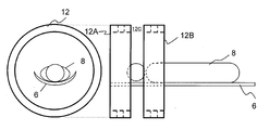
- a cylindrical detector ring 12 in which a large number of PET detectors 10 are arranged in a circumferential direction and an axial direction is arranged in a tunnel shape, and a measurement solid angle is measured. And the distribution of nuclides in the tunnel must be obtained by three-dimensional image reconstruction.
- the long tunnel-like patient port increases the psychological stress of the patient 8 being examined on the bed 6 and provides access to the patient 8 from the outside (for example, for cancer treatment, which is the main purpose of the present invention). It also becomes an obstacle when a radiation beam is irradiated to a patient's affected area.
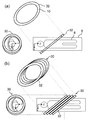
- the detector ring 12 is mainly circular, and the PET detector 10 is stacked in a direction perpendicular to the cut surface of the detector ring 12.
- the applicant arranges the detector rings 12A and 12B divided into a plurality (two in FIG. 2) in the body axis direction, and physically opens the field of view.
- An open PET apparatus also referred to as Open PET
- a region also referred to as an open field of view
- This open-type PET apparatus can be used for real-time PET / CT in addition to enabling PET diagnosis during treatment and whole-body simultaneous imaging, which was impossible with conventional PET apparatuses. Specifically, since it is possible to treat the open visual field from the gap 12C between the detector rings 12A and 12B, taking radiation cancer treatment as an example, the position of the cancer can be determined with an open PET apparatus. It is possible to irradiate a radiation treatment beam while confirming, or to visualize the radiation treatment beam irradiation field in real time with an open PET apparatus.
- the detector ring needs to cover the front and back of the irradiation field, which not only increases the number of detectors but complicates the configuration, and also restricts the direction of access. There is a problem.
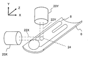
- FIG. 1 An example of a particle beam cancer treatment device such as a heavy particle beam or a proton beam is shown in FIG.
- This apparatus includes, for example, two gates, a horizontal irradiation port 20X and a vertical irradiation port 20Y.
- the irradiation port is not fixed, and there may be provided a rotating gantry that rotates around the patient 8, and the rotating gantry system is mainly used in the proton beam cancer treatment apparatus.
- the axis along the horizontal irradiation treatment beam 22X is the X axis
- the axis along the vertical irradiation treatment beam 22Y is the Y axis
- the axis perpendicular to the Y axis and the X axis is Z.
- the Z-axis often coincides with an axis in the direction of the body axis of the patient 8.
- PET measurement during irradiation is required to confirm the irradiation field 24 in the body of the patient 8.
- Non-Patent Document 1 describes that a detector ring 12 is installed obliquely to secure an open area of width C as shown in FIG. Yes.
- the detector ring 12 is a perfect circle as shown in the upper left of FIG. 4, and the PET detector 10 is stacked in a direction perpendicular to the cut surface of the detector ring 12. Therefore, the inner space shape of the detector ring viewed from the direction perpendicular to the Z axis (the left direction in the figure) is an ellipse.
- Non-Patent Document 1 In order to ensure a sufficient open area width C in Non-Patent Document 1, it is necessary to increase the diameter of the detector ring 12. As a result, the apparatus becomes larger and the number of PET detectors used increases, so that the apparatus cost also increases. Further, as the diameter of the detector ring 12 increases, the spatial resolution decreases due to the angular swing.
- the irradiation port When combined with particle beam therapy, in order to suppress the spread of the treatment beam, it is desirable that the irradiation port be as close as possible to the patient. However, as shown in FIG. Thus, the irradiation port (horizontal irradiation port 20X in FIG. 4) cannot be brought close to the patient 8. Although FIG. 4 shows an example of horizontal irradiation, the method of Non-Patent Document 1 cannot change the orientation of the detector ring 12 in accordance with an arbitrary irradiation direction. It also had the problem that it could not be used for a rotating gantry.
- the PET detector is stacked in a direction perpendicular to the cut surface of the detector ring.
- the PET detector is attached to the long axis of the bed as in the present invention. Is described as being stacked in a direction parallel to the. However, this is to prevent the detector from obstructing the patient's line of sight, and as in Non-Patent Document 1, in order to allow access to the patient, the bed is oriented perpendicular to its long axis. It is not considered to form an open space that penetrates the space.
- the present invention has been made to solve the above-mentioned conventional problems, and it is possible to access an inspection object while ensuring an open space that penetrates the bed in a direction perpendicular to the long axis thereof, and a detector. It is an object of the present invention to reduce the cost of the apparatus by reducing the size of the ring and thus the apparatus and reducing the number of PET detectors.
- the detector arrangement of the PET apparatus of the present invention has a shape in which a cylinder is cut out by two planes inclined with respect to the cut end of the cylinder.
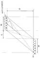
- the inner diameter D and the width W of the detector ring 12 are calculated to ensure the following.
- the inner diameter viewed in the direction perpendicular to the central axis of the detector ring 30 is D and the width W, and the size of the detector ring 30 is that of the bed 6.
- D B as the last size to enter. Then, D and W for securing the open area width of the width C are calculated.
- FIG. 6 The calculation results are shown in FIG.
- the size of one PET detector was an area of 5 cm ⁇ 5 cm.
- FIG. 7A shows the apparatus parameters of the conventional example when the number of detectors is 200
- FIG. 7B shows the apparatus parameters of the present invention example.
- a geometrical relationship as shown in FIG. 8 was used for calculating the major radius a of the ellipse of the cut of the detector ring 30.
- the present invention can achieve high sensitivity with a smaller number of detectors, the number of detectors can be reduced and the cost can be reduced.
- the present invention has been made based on such knowledge, and the plane of the cut surface of the detector ring in which a plurality of PET detectors are arranged is inclined so as not to be orthogonal to the long axis of the bed on which the inspection object is placed.
- each PET detector is stacked in a direction parallel to the long axis of the bed.
- the open space can be arranged according to the access direction to the inspection object.
- the detector ring can be rotated in accordance with the access direction to the inspection object.
- the detector ring can be moved according to the access position to the inspection object.
- the detector ring can be rotated in accordance with the horizontal rotation of the bed.
- the detector ring can be supported by a robot arm.
- the detector ring can be configured by laminating unit rings in which the PET detectors are arranged in an elliptical shape or a polygonal shape in a direction parallel to the long axis of the bed.
- the unit rings can be arranged in a staircase pattern.
- the plane of the cut surface of the detector ring can be rotated to a position perpendicular to the long axis of the bed.
- each unit ring can be translated to a position that matches each other.
- each unit ring can be translated in synchronization with the rotation of the unit ring.
- each PET detector is stacked in a direction parallel to the long axis of the bed by gradually shifting the detector unit in which the plurality of PET detectors are arranged in the long axis direction of the bed. can do.
- the amount of displacement of the detector unit in the bed major axis direction can be a sine wave on the drawing in which the detector ring is developed on a plane.
- the deviation amount of the detector unit can be made variable.
- each PET detector can be inclined according to the amount of deviation of the detector unit so as to go to the center point of the detector ring.
- the present invention also provides a PET combined device comprising the above-described inclined PET device and a second device that performs treatment and examination in an open space of the inclined PET device.
- the second apparatus can be a radiation therapy apparatus, a particle beam therapy apparatus, or an X-ray transmission apparatus.
- the inclined PET device and the second device can be moved and rotated together without interfering with each other.
- At least a part of the second device can be supported on the detector ring of the inclined PET device.
- the apparatus can be reduced in size and the number of PET detectors can be reduced, so that the apparatus cost can be reduced.
- FIG. 6 is a diagram showing an example of apparatus parameters when the number of detectors is 200 in FIG.
- FIG. 17 is an exploded perspective view showing an example of a specific mechanism for realizing the modification of FIG. Same side view Same top view
- the figure which shows the other example of the method of arranging a PET detector The figure which shows the modification of FIG.
- a detector ring 30 in which a plurality of PET detectors 10 are arranged in the circumferential direction is connected to the long axis (Z axis in the figure) of the patient 8 to be examined.
- An open space having a width C that penetrates the bed 6 in a direction (vertical direction in the figure) perpendicular to the major axis is formed to allow access to the patient 8.
- the PET detectors 10 are stacked in the horizontal direction parallel to the long axis of the bed 6.
- the width C of the open space is, for example, equal to or greater than the width of the treatment beam.
- the PET detector 10 constituting the detector ring 30 is laminated in a direction that is not perpendicular to the cut end.
- the direction in which the PET detectors 10 are stacked is close to the Z axis or the long axis of the bed 6.
- the detector ring 30 has a shape like a true cylindrical detector ring 12 similar to the conventional example, which is cut obliquely at two parallel surfaces that are not perpendicular to the axis.
- the cross section of the detector ring 30 as viewed from the Z-axis direction is a perfect circle, and when viewed from the direction perpendicular to the cut surface of the detector ring 30, it is elliptical as shown in the upper left of the figure. Yes.
- single event data of annihilation radiation detected by the PET detector 10 is converted into coincidence data specifying a coincidence line by the coincidence counting circuit 31A and sequentially stored in the data collection system 31B. Then, after accumulating the measurement data for a certain time, the image reconstruction system 31C performs an image reconstruction calculation, and displays or stores the image of the irradiation field on the display / storage system 31D.
- FIG. 10 shows a second embodiment of the present invention in which a horizontal irradiation particle beam therapy system having a horizontal irradiation port 20X is combined with the first embodiment.
- the horizontal irradiation port 20X can be brought closer to the irradiation field 24 of the patient 8 to suppress the spread of the treatment beam 22X.
- a PET image of the irradiation field 24 can be obtained by the same method as in the first embodiment.
- FIG. 11 shows a third embodiment of the present invention in which a vertical irradiation particle beam therapy system having a vertical irradiation port 20Y is combined with the first embodiment.
- the vertical irradiation port 20Y can be brought close to the irradiation field 24 of the patient 8 to suppress the spread of the treatment beam 22Y.
- a PET image of the irradiation field 24 can be obtained by the same method as in the first embodiment.
- the detector ring 30 By making the detector ring 30 rotatable about the Z axis or an axis in the vicinity of the Z axis, the horizontal irradiation shown in FIG. 10 and the vertical irradiation shown in FIG. It is also possible to enable irradiation.
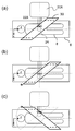
- FIG. 12 shows a fourth embodiment of the present invention in which the detector ring 30 can be translated in the Z-axis direction in accordance with the movement of the irradiation field 24.
- FIG. 12A the case where the irradiation field 24 is in the center has been taken as an example.
- the detector ring 30 may be shifted in the Z axis plus direction (right in the figure).
- FIG. 12C when the irradiation field 24 is moved in the minus direction of the X axis, the detector ring 30 can be further rotated by 180 ° around the Z axis (or on the XZ plane). It ’s fine.
- FIG. 12 shows an example of horizontal irradiation, but the same can be applied to vertical irradiation.
- non-coplanar irradiation in which the long axis of the bed is different from the Z-axis may be performed particularly in the irradiation of the head.
- the detector ring 30 may be rotated in accordance with the rotation of the bed 6 as in the fifth embodiment shown in FIG.
- FIG. 13 shows an example of horizontal irradiation, the same applies to the case of vertical irradiation.
- the open region width C is enlarged by slightly rotating the detector ring 30. be able to.
- the detector ring 30 can be rotated clockwise as indicated by an arrow.
- the open area width can be expanded from C to C ′.
- FIG. 15 shows a seventh embodiment of the present invention in which the detector ring 30 is supported by a robot arm 40 so that, for example, both (a) horizontal irradiation and (b) vertical irradiation can be handled.
- reference numeral 42 denotes a fulcrum of the robot arm. This embodiment can also be applied to a rotating gantry.
- FIG. 16 shows an example.
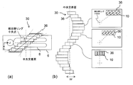
- the PET detectors 10 are arranged in an ellipse on the same plane to form a unit ring 32.
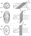
- the unit rings 32 formed in this way are arranged in a step shape in a direction parallel to the Z axis as shown in FIG. Note that the unit ring 32 is not necessarily elliptical, and may be polygonal.
- the distance that the radiation crosses the body becomes longer if the detector ring 30 is tilted as shown in FIG.
- the radiation is strongly absorbed by the body, and the amount of radiation that can be detected is reduced. Therefore, in order to reduce the degree of radiation absorption by the patient's body, the entire detector ring 30 can be rotated along the XZ plane as shown in FIG. Note that the field of view is limited when measuring a long photographic object such as the patient 8 on the bed 6. Therefore, as shown in FIG. 17C, the field of view can be expanded by aligning the unit rings 32.
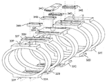
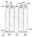
- FIG. 18 (disassembled perspective view), FIG. 19 (side view), and FIG. 20 (top view) show an example of a specific mechanism for performing the deformation from (b) to (c) in FIG.
- This mechanism includes, for example, two pins 32P protruding above and below each of the five unit rings 32A to 32E, a flange 32F formed with a long hole 32H through which the pins 32P are inserted, and a unit ring 32A.
- gears 34A to 34E disposed on the upper portions of the unit rings 32A to 32E, respectively, for sliding with a constant width.
- all the unit rings 32A to 32E can be interlocked and moved from the step shape to the cylinder shape by the rotation of the central gear 34C.
- movement may be manual, it can also be electrified.
- the detector ring 30 of the present invention can be constructed by shifting the bucket 36 little by little in the Z-axis direction.
- the shift amount of the bucket 36 in the Z-axis direction is as shown in the development view of the detector ring 30 shown in FIG.
- DOI Depth-of-interaction
- JP-A-6-337289, JP-A-11-142523, JP-A-2004-132930, and JP-A-2004 capable of discriminating the radiation position in the thickness direction of the scintillator.
- FIG. 23A An example of a specific mechanism for enabling the bucket 36 to move is shown in FIG.
- the PET detector 10 is housed in a detector case 36C constituting the bucket 36, covered with a lid 36L, and adjacent to a long hole 36H formed in a flange 36F of the detector case 36C.
- the nut 36N By fixing the nut 36N through the bolt 36B of the detector case 36C, the bucket 36 can be moved in the longitudinal direction as shown in FIG.
- the main axis of the PET detector 10 can be inclined according to the position of the bucket 36 so that the main axis of the PET detector 10 is directed to the center point of the detector ring 30. .
- the angle of radiation incident on the PET detector can be made nearly vertical, and the position discrimination performance can be maintained even when a normal PET detector that is not a DOI detector is used.
- the detection width in the Z-axis direction is widened.
- the originally elliptical detector ring has a problem that sensitivity decreases due to a decrease in solid angle in the major axis direction of the ellipse compared to the minor axis direction of the ellipse.
- By tilting the main axis of the PET detector 10 in this way there is a problem. The closer to the long axis direction, the wider the detection width and the more the solid angle can be suppressed.
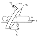
- FIG. 25 shows an eighth embodiment of the present invention relating to a PET composite apparatus in which the PET apparatus according to the present invention is combined with an X-ray transmission apparatus.
- an X-ray source 60 and an X-ray detector 62 independent of the detector ring 30 are provided by an arm 64 so that X-rays to be irradiated pass through an open space.
- the accuracy of the needle biopsy is improved by confirming the positional relationship between the shape of the bone or organ around the tumor and the needle of the needle biopsy with an X-ray image. It becomes possible.
- a PET / CT composite apparatus can be configured by rotating the entire PET apparatus and X-ray transmission apparatus.
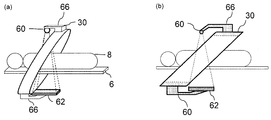
- FIG. 26 (a) (perspective view) and (b) (cross-sectional view), a ninth embodiment of the present invention in which the X-ray source 60 and the X-ray detector 62 are fixed to the detector ring 30 using a holder 66 is shown. Show. According to the present embodiment, the arm as in the eighth embodiment can be omitted, and the PET composite apparatus can be configured at low cost.
- a PET / CT combined apparatus having a simultaneous field of view can be configured by rotating the entire apparatus.
- the PET apparatus concerning this invention was combined with the radiotherapy apparatus and the X-ray transmissive apparatus, the apparatus combined with a PET apparatus is not limited to these. It is also possible to use the PET apparatus alone.
- the PET detectors are not necessarily arranged densely in the circumferential direction and the axial direction of the detector ring, and there may be a gap between the PET detectors.
- An inclined PET apparatus and a PET combined apparatus suitable for combination with a radiotherapy apparatus or an X-ray transmission apparatus can be obtained.
Landscapes
- Health & Medical Sciences (AREA)
- Life Sciences & Earth Sciences (AREA)
- Engineering & Computer Science (AREA)
- Medical Informatics (AREA)
- Biomedical Technology (AREA)
- Physics & Mathematics (AREA)
- Molecular Biology (AREA)
- High Energy & Nuclear Physics (AREA)
- Radiology & Medical Imaging (AREA)
- Veterinary Medicine (AREA)
- Pathology (AREA)
- Nuclear Medicine, Radiotherapy & Molecular Imaging (AREA)
- Public Health (AREA)
- General Health & Medical Sciences (AREA)
- Animal Behavior & Ethology (AREA)
- Surgery (AREA)
- Biophysics (AREA)
- Heart & Thoracic Surgery (AREA)
- Optics & Photonics (AREA)
- General Physics & Mathematics (AREA)
- Spectroscopy & Molecular Physics (AREA)
- Nuclear Medicine (AREA)
Abstract
Description
8…患者(検査対象)
10…PET検出器
20X、20Y…照射ポート
22X、22Y…治療ビーム
24…照射野
30…検出器リング
32…単位リング
36…バケット
60…X線源
62…X線検出器
64…アーム
66…ホルダ
Claims (21)
- 複数のPET検出器を並べた検出器リングの切り口の平面が、検査対象を載せるベッドの長軸に直交しないように傾斜しており、検査対象へのアクセスを可能とするための、ベッドをその長軸と垂直な方向に貫く開放空間が形成された傾斜PET装置において、
各PET検出器をベッドの長軸と平行な方向に積層配置したことを特徴とする傾斜PET装置。 - 前記開放空間が、検査対象へのアクセス方向に合わせて配置されていることを特徴とする請求項1に記載の傾斜PET装置。
- 前記検出器リングが、検査対象へのアクセス方向に合わせて回転可能とされていることを特徴とする請求項1又は2に記載の傾斜PET装置。
- 前記検出器リングが、検査対象へのアクセス位置に合わせて移動可能とされていることを特徴とする、請求項1又は3に記載の傾斜PET装置。
- 前記ベッドの水平回転に合わせて、前記検出器リングが回転するようにされていることを特徴とする請求項1に記載の傾斜PET装置。
- 前記検出器リングが、ロボットアームに支持されていることを特徴とする請求項1に記載の傾斜PET装置。
- 前記PET検出器を楕円状又は多角形状に並べた単位リングをベッドの長軸と平行な方向に積層することにより前記検出器リングが構成されていることを特徴とする請求項1に記載の傾斜PET装置。
- 前記単位リングが、階段状に並べられていることを特徴とする請求項7に記載の傾斜PET装置。
- 前記検出器リングの切り口の平面が、ベッドの長軸と垂直な位置まで回転可能とされていることを特徴とする請求項7に記載の傾斜PET装置。
- 前記各単位リングが、互いに一致する位置まで平行移動可能とされていることを特徴とする請求項7に記載の傾斜PET装置。
- 前記単位リングの回転と同期して、各単位リングが平行移動するようにされていることを特徴とする請求項9に記載の傾斜PET装置。
- 前記PET検出器を複数個ベッドの長軸方向に並べた検出器ユニットを、ベッドの長軸方向に少しずつずらすことにより、各PET検出器がベッドの長軸と平行な方向に積層配置されていることを特徴とする請求項1に記載の傾斜PET装置。
- 前記検出器ユニットのベッド長軸方向のずれ量が、検出器リングを平面上に展開した図面上において、正弦波であることを特徴とする請求項12に記載の傾斜PET装置。
- 前記検出器ユニットのずれ量が可変とされていることを特徴とする請求項12に記載の傾斜PET装置。
- 各PET検出器の主軸が、検出器リングの中央点に向かうように、検出器ユニットのずれ量に応じて傾斜されていることを特徴とする請求項12に記載の傾斜PET装置。
- 請求項1乃至15のいずれかに記載の傾斜PET装置と、
該傾斜PET装置の開放空間で治療や検査を行う第2の装置と、
を備えた事を特徴とするPET複合装置。 - 前記第2の装置が、放射線治療装置であることを特徴とする請求項16に記載のPET複合装置。
- 前記第2の装置が、粒子線治療装置であることを特徴とする請求項16に記載のPET複合装置。
- 前記第2の装置が、X線透過装置であることを特徴とする請求項16に記載のPET複合装置。
- 前記傾斜PET装置と、前記第2の装置が、互いに干渉することなく、一体となって移動や回転することを特徴とする請求項16乃至19のいずれかに記載のPET複合装置。
- 前記傾斜PET装置の検出器リングに、前記第2の装置の少なくとも一部が支持されていることを特徴とする請求項16乃至20のいずれかに記載のPET複合装置。
Priority Applications (4)
| Application Number | Priority Date | Filing Date | Title |
|---|---|---|---|
| US14/113,334 US9538964B2 (en) | 2011-05-30 | 2011-05-30 | Inclined pet device and pet combined device |
| PCT/JP2011/062394 WO2012164664A1 (ja) | 2011-05-30 | 2011-05-30 | 傾斜pet装置及びpet複合装置 |
| JP2013517727A JP5808024B2 (ja) | 2011-05-30 | 2011-05-30 | 傾斜pet装置及びpet複合装置 |
| DE112011105202.2T DE112011105202T5 (de) | 2011-05-30 | 2011-05-30 | Geneigte PET-Vorrichtung und PET-Kombinationsvorrichtung |
Applications Claiming Priority (1)
| Application Number | Priority Date | Filing Date | Title |
|---|---|---|---|
| PCT/JP2011/062394 WO2012164664A1 (ja) | 2011-05-30 | 2011-05-30 | 傾斜pet装置及びpet複合装置 |
Publications (1)
| Publication Number | Publication Date |
|---|---|
| WO2012164664A1 true WO2012164664A1 (ja) | 2012-12-06 |
Family
ID=47258550
Family Applications (1)
| Application Number | Title | Priority Date | Filing Date |
|---|---|---|---|
| PCT/JP2011/062394 Ceased WO2012164664A1 (ja) | 2011-05-30 | 2011-05-30 | 傾斜pet装置及びpet複合装置 |
Country Status (4)
| Country | Link |
|---|---|
| US (1) | US9538964B2 (ja) |
| JP (1) | JP5808024B2 (ja) |
| DE (1) | DE112011105202T5 (ja) |
| WO (1) | WO2012164664A1 (ja) |
Cited By (2)
| Publication number | Priority date | Publication date | Assignee | Title |
|---|---|---|---|---|
| US9226717B2 (en) | 2013-10-30 | 2016-01-05 | National Institute Of Radiological Sciences | Helmet-type PET device |
| JP2019000302A (ja) * | 2017-06-14 | 2019-01-10 | キヤノンメディカルシステムズ株式会社 | アンギオct装置 |
Families Citing this family (2)
| Publication number | Priority date | Publication date | Assignee | Title |
|---|---|---|---|---|
| CN108433739B (zh) * | 2018-05-24 | 2024-07-05 | 明峰医疗系统股份有限公司 | 一种可旋转的pet探测器环的安装方法 |
| US10926111B2 (en) * | 2019-03-21 | 2021-02-23 | Vieworks Co., Ltd. | Bragg peak detector using scintillators and method of operating the same |
Citations (10)
| Publication number | Priority date | Publication date | Assignee | Title |
|---|---|---|---|---|
| JPH02122378U (ja) * | 1989-03-17 | 1990-10-05 | ||
| JP2008538312A (ja) * | 2005-04-19 | 2008-10-23 | ドイチェス クレブスフォルシュングスツェントルム シュティフトゥング デス エッフェントリッヒェンレヒツ | デュアルモダリティイメージングシステムおよび方法 |
| WO2008129666A1 (ja) * | 2007-04-17 | 2008-10-30 | National Institute Of Radiological Sciences | Pet装置、及び、その画像再構成方法 |
| JP2009042029A (ja) * | 2007-08-08 | 2009-02-26 | Toshiba Corp | Pet装置 |
| WO2009122561A1 (ja) * | 2008-04-01 | 2009-10-08 | 独立行政法人放射線医学総合研究所 | 開放型pet装置 |
| WO2010016107A1 (ja) * | 2008-08-05 | 2010-02-11 | 株式会社島津製作所 | Pet装置 |
| JP2010094421A (ja) * | 2008-10-20 | 2010-04-30 | Toshiba Corp | 粒子線治療装置、及び粒子線治療装置制御方法 |
| JP2010101666A (ja) * | 2008-10-22 | 2010-05-06 | Hitachi Medical Corp | 核医学診断装置 |
| JP2010223956A (ja) * | 2009-02-25 | 2010-10-07 | Action Research:Kk | Pet支持装置 |
| JP2011069636A (ja) * | 2009-09-24 | 2011-04-07 | Shimadzu Corp | ポジトロンct装置 |
Family Cites Families (3)
| Publication number | Priority date | Publication date | Assignee | Title |
|---|---|---|---|---|
| EP2197547B1 (en) * | 2007-09-13 | 2014-06-11 | Toby D. Henderson | Imaging positioning system having robotically positioned d-arm |
| CN102170937B (zh) * | 2008-12-16 | 2014-01-29 | 株式会社岛津制作所 | 粒子线治疗装置 |
| EP2412404A1 (en) * | 2009-03-23 | 2012-02-01 | National Institute of Radiological Sciences | Concealment-type radiotherapy/imaging combined device |
-
2011
- 2011-05-30 US US14/113,334 patent/US9538964B2/en active Active
- 2011-05-30 WO PCT/JP2011/062394 patent/WO2012164664A1/ja not_active Ceased
- 2011-05-30 JP JP2013517727A patent/JP5808024B2/ja active Active
- 2011-05-30 DE DE112011105202.2T patent/DE112011105202T5/de not_active Withdrawn
Patent Citations (10)
| Publication number | Priority date | Publication date | Assignee | Title |
|---|---|---|---|---|
| JPH02122378U (ja) * | 1989-03-17 | 1990-10-05 | ||
| JP2008538312A (ja) * | 2005-04-19 | 2008-10-23 | ドイチェス クレブスフォルシュングスツェントルム シュティフトゥング デス エッフェントリッヒェンレヒツ | デュアルモダリティイメージングシステムおよび方法 |
| WO2008129666A1 (ja) * | 2007-04-17 | 2008-10-30 | National Institute Of Radiological Sciences | Pet装置、及び、その画像再構成方法 |
| JP2009042029A (ja) * | 2007-08-08 | 2009-02-26 | Toshiba Corp | Pet装置 |
| WO2009122561A1 (ja) * | 2008-04-01 | 2009-10-08 | 独立行政法人放射線医学総合研究所 | 開放型pet装置 |
| WO2010016107A1 (ja) * | 2008-08-05 | 2010-02-11 | 株式会社島津製作所 | Pet装置 |
| JP2010094421A (ja) * | 2008-10-20 | 2010-04-30 | Toshiba Corp | 粒子線治療装置、及び粒子線治療装置制御方法 |
| JP2010101666A (ja) * | 2008-10-22 | 2010-05-06 | Hitachi Medical Corp | 核医学診断装置 |
| JP2010223956A (ja) * | 2009-02-25 | 2010-10-07 | Action Research:Kk | Pet支持装置 |
| JP2011069636A (ja) * | 2009-09-24 | 2011-04-07 | Shimadzu Corp | ポジトロンct装置 |
Cited By (2)
| Publication number | Priority date | Publication date | Assignee | Title |
|---|---|---|---|---|
| US9226717B2 (en) | 2013-10-30 | 2016-01-05 | National Institute Of Radiological Sciences | Helmet-type PET device |
| JP2019000302A (ja) * | 2017-06-14 | 2019-01-10 | キヤノンメディカルシステムズ株式会社 | アンギオct装置 |
Also Published As
| Publication number | Publication date |
|---|---|
| JPWO2012164664A1 (ja) | 2014-07-31 |
| US9538964B2 (en) | 2017-01-10 |
| DE112011105202T5 (de) | 2014-01-30 |
| US20140046180A1 (en) | 2014-02-13 |
| JP5808024B2 (ja) | 2015-11-10 |
Similar Documents
| Publication | Publication Date | Title |
|---|---|---|
| US8594404B2 (en) | PET scanner and image reconstruction method thereof | |
| JP5339551B2 (ja) | 遮蔽型放射線治療・画像化複合装置、及び、その制御プログラム | |
| JP5360914B2 (ja) | 検出器シフト型放射線治療・pet複合装置 | |
| US7604405B2 (en) | Integrated quality assurance for an image guided radiation treatment delivery system | |
| US10124193B2 (en) | X-ray therapy system and irradiation field determining method | |
| WO2010103645A1 (ja) | 多目的pet装置 | |
| US8995609B2 (en) | X-ray compton scatter imaging on volumetric CT systems | |
| JP6938757B2 (ja) | 光子発射検出装置およびそれを有するホウ素中性子捕捉治療システム | |
| WO2010013346A1 (ja) | 放射線治療・pet複合装置 | |
| KR101948800B1 (ko) | 3차원 산란 방사선 영상장치와 이를 갖는 방사선 의료장비 및 3차원 산란 방사선 영상장치의 배치 방법 | |
| JP5808024B2 (ja) | 傾斜pet装置及びpet複合装置 | |
| Moustakis et al. | A novel approach to SBRT patient quality assurance using EPID-based real-time transit dosimetry: a step to QA with in vivo EPID dosimetry | |
| JP2010101666A (ja) | 核医学診断装置 | |
| US20060269049A1 (en) | Dual-detector, simulation CT, and real time function imaging | |
| Yamaya et al. | Prospects for applying radioactive ion beams in particle therapy | |
| KR101749324B1 (ko) | 3차원 산란 방사선 영상장치 및 이를 갖는 방사선 의료장비 | |
| Oh et al. | Monte Carlo simulation study of an in vivo four-dimensional tracking system with a diverging collimator for monitoring radiation source (Ir-192) location during brachytherapy: proof of concept and feasibility | |
| US10459095B2 (en) | Flat-plate PET imaging device with window | |
| Yamaya et al. | Imaging simulations of an “OpenPET” geometry with shifting detector rings | |
| WO2020195685A1 (ja) | 核医学撮像装置 | |
| Yamaya et al. | OpenPET enabling PET imaging during radiotherapy | |
| Latif et al. | technology and medical imaging | |
| Yamaguchi et al. | A feasibility study of a molecular-based patient setup verification method using a parallel-plane PET system | |
| KR20180077442A (ko) | 적층식 평행다공형 콜리메이터 | |
| Cowell | Dose delivery accuracy of visually gated SBRT: a stress test for clinical acceptance |
Legal Events
| Date | Code | Title | Description |
|---|---|---|---|
| 121 | Ep: the epo has been informed by wipo that ep was designated in this application |
Ref document number: 11867038 Country of ref document: EP Kind code of ref document: A1 |
|
| ENP | Entry into the national phase |
Ref document number: 2013517727 Country of ref document: JP Kind code of ref document: A |
|
| WWE | Wipo information: entry into national phase |
Ref document number: 14113334 Country of ref document: US |
|
| WWE | Wipo information: entry into national phase |
Ref document number: 112011105202 Country of ref document: DE Ref document number: 1120111052022 Country of ref document: DE |
|
| 122 | Ep: pct application non-entry in european phase |
Ref document number: 11867038 Country of ref document: EP Kind code of ref document: A1 |