WO2012161208A1 - ノイズ低減装置、表示装置、ノイズ低減方法およびノイズ低減プログラム - Google Patents
ノイズ低減装置、表示装置、ノイズ低減方法およびノイズ低減プログラム Download PDFInfo
- Publication number
- WO2012161208A1 WO2012161208A1 PCT/JP2012/063150 JP2012063150W WO2012161208A1 WO 2012161208 A1 WO2012161208 A1 WO 2012161208A1 JP 2012063150 W JP2012063150 W JP 2012063150W WO 2012161208 A1 WO2012161208 A1 WO 2012161208A1
- Authority
- WO
- WIPO (PCT)
- Prior art keywords
- pixel
- noise reduction
- noise
- unit
- information indicating
- Prior art date
- Legal status (The legal status is an assumption and is not a legal conclusion. Google has not performed a legal analysis and makes no representation as to the accuracy of the status listed.)
- Ceased
Links
Images

















Classifications
-
- H—ELECTRICITY
- H04—ELECTRIC COMMUNICATION TECHNIQUE
- H04N—PICTORIAL COMMUNICATION, e.g. TELEVISION
- H04N5/00—Details of television systems
- H04N5/14—Picture signal circuitry for video frequency region
- H04N5/21—Circuitry for suppressing or minimising disturbance, e.g. moiré or halo
Definitions
- the present invention relates to a noise reduction device, a display device, a noise reduction method, and a noise reduction program.
- noise components are mixed in the transmission path, and the receiver itself But noise components are mixed.
- an image input device for example, a television imaging device
- noise components are mixed in the transmission path, and the receiver itself
- noise components are mixed.
- analog television broadcasting when the signal level of a received video signal is low, a noise component is significantly mixed in the video signal.
- noise components are significantly mixed in the video signal.
- Patent Document 1 by using the magnitude relationship between the input video signal and the output of the median filter, the smoothing value of the noise component in the vertical blanking period is subtracted from or added to the input signal.
- a noise reduction circuit for reducing residual noise components is described.
- the noise reduction circuit needs to perform noise reduction using a total of three frames including a target frame that is a target for noise reduction and two frames before and after.
- the conventional noise reduction circuit needs to include two frame memories for storing data for two fields when reducing noise between frames. Therefore, there is a problem that the circuit scale of the noise reduction circuit is increased, and as a result, the production cost is increased.
- the present invention has been made in view of the above problems, and provides a technique that makes it possible to reduce the capacity of a memory that stores image data when noise superimposed on an image is reduced. Let it be an issue.
- a first aspect of the present invention is a size relationship storage unit that stores information indicating a size relationship between a target pixel that is a target for noise reduction and a first comparison pixel that is separated by a predetermined interval;
- a noise reduction device comprising: a noise reduction unit that reads information indicating the magnitude relationship from a relationship storage unit and reduces noise of the target pixel based on the read information indicating the magnitude relationship.
- the image processing apparatus further includes a pixel value storage unit that stores information indicating a pixel value of a second comparison pixel that is separated from the target pixel by a predetermined interval
- the noise reduction unit includes: Information indicating the pixel value of the second comparison pixel is read from the pixel value storage unit, and based on the read pixel value of the second comparison pixel, the pixel value of the target pixel, and the magnitude relationship, Noise of the target pixel may be reduced.
- the noise reduction unit calculates a magnitude relationship between a pixel value of the second comparison pixel and a pixel value of the target pixel, and indicates the calculated magnitude relationship May be stored in the magnitude relation storage unit.
- the pixel value of the detection pixel that is a target for detecting the amount of noise included in the image, and the image in the image preceding the image including the detection pixel by a predetermined number of frames.
- a pixel value of a previous frame pixel that is a pixel corresponding to a position of the detection pixel, a pixel value of a pixel separated from the detection pixel by a first interval in an image including the detection pixel, and a first value from the detection pixel
- a calculation unit for calculating a predetermined pixel value based on pixel values of pixels separated by an interval of two, and a noise amount estimation for estimating a noise amount on the image based on the frequency of the calculated value May be further provided.
- the noise amount estimation unit may estimate the frequency mode frequency as the amount of noise included in the image.
- the detection pixel may be located between a pixel separated by the first interval and a pixel separated by the second interval.
- the first interval and the second interval may be predetermined intervals in the vertical direction in an image including the detection pixels.
- an interval between the target pixel and the first comparison pixel and an interval between the target pixel and the second comparison pixel are frame intervals, and the noise reduction unit May reduce noise between frames of the target pixel.
- an interval between the target pixel and the first comparison pixel and an interval between the target pixel and the second comparison pixel are within an image including the target pixel.
- the noise reduction unit may reduce horizontal noise in the image of the target pixel.
- an interval between the target pixel and the first comparison pixel and an interval between the target pixel and the second comparison pixel are within an image including the target pixel. It is a vertical interval, and the noise reduction unit may reduce noise in the vertical direction in the image of the target pixel.
- the second aspect of the present invention is a size relationship storage unit that stores information indicating a size relationship between a target pixel that is a target for noise reduction and a first comparison pixel that is separated by a predetermined interval;
- the display device includes a noise reduction device that includes a noise reduction unit that reads information indicating the magnitude relationship from a relationship storage unit and reduces noise of the target pixel based on the read information indicating the magnitude relationship.
- information indicating a magnitude relationship between a target pixel that is a target for noise reduction and a comparison pixel that is separated by a predetermined interval is stored, information that indicates the magnitude relationship is read, and This is a noise reduction method for reducing the noise of the target pixel based on the read information indicating the magnitude relationship.
- information indicating a magnitude relationship between a target pixel that is a target for noise reduction and a comparison pixel that is separated by a predetermined interval is stored in a computer, and the information that indicates the magnitude relationship is stored.
- the capacity of a memory for storing image data when reducing noise superimposed on an image, the capacity of a memory for storing image data can be reduced.
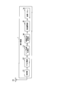
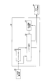
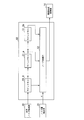
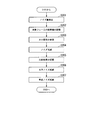
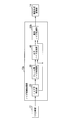
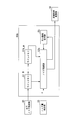
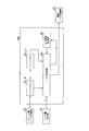
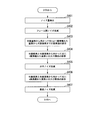
- 1 is a schematic block diagram of a display device according to a first embodiment. It is a figure which shows the connection relation of the signal of a liquid-crystal drive part and a liquid crystal panel. It is a schematic block diagram of the noise reduction process part in 1st Embodiment. It is a functional block diagram of the noise reduction part between frames in a 1st embodiment. It is a figure for demonstrating the process of the noise reduction part between flame
- FIG. 1 is a schematic block diagram of a display device 1 according to the first embodiment.
- a display device 1 includes a detection unit 11, a Y / C (luminance signal / color difference signal) separation unit 12, a noise reduction processing unit 13, and RGB (Red: red, Green: green, Blue: blue).
- a conversion unit 14, a liquid crystal driving unit 15, and a liquid crystal panel 16 are provided.
- the display device 1 is connected to the antenna 10.
- the detection unit 11 receives high-frequency signals of image data of a plurality of channels of terrestrial analog television broadcast supplied from an external antenna 10. Then, the detection unit 11 extracts a modulation signal of a desired channel from the high-frequency signal supplied from the antenna, converts the extracted modulation signal into a baseband signal, and outputs it to the Y / C separation unit 12.
- the Y / C separation unit 12 demodulates the supplied baseband signal, separates it into a luminance signal, a color difference signal, and a color difference signal, and converts each separated signal into a digital signal at a predetermined sampling frequency. . Further, the Y / C separation unit 12 outputs the luminance value Y data converted into the digital signal, and the image data including the color difference Cb data and the color difference Cr data to the noise reduction processing unit 13.
- the noise reduction processing unit 13 calculates the noise level in units of frames or fields.
- the noise reduction processing unit 13 compares the supplied luminance value Y data, color difference Cb data, and color difference Cr data between frames (pixel space in which the pixels are arranged) or between pixels in the same frame, and processes target pixels. It is determined whether or not noise is superimposed on.
- the noise reduction processing unit 13 adds or subtracts a noise amount ⁇ estimated by a method described later from a target pixel determined to have noise superimposed thereon, thereby reducing noise of the target pixel targeted for noise reduction. Perform the process.
- the noise reduction processing unit 13 outputs the image signal after the noise reduction processing to the image format conversion unit 14.
- noise processing is performed for each field, and when the video signal is non-interlaced, noise processing is performed for each frame.
- the image format conversion unit 14 converts the image signal supplied from the noise reduction processing unit 13 into a progressive signal.
- the image format conversion unit 14 adjusts the number of pixels (scaling processing) in accordance with the resolution of the liquid crystal panel 16 for the progressive signal. Then, the image format conversion unit 14 converts the video signal with the adjusted number of pixels into an RGB signal (Red, Green, Blue color video signal), and outputs the converted RGB signal to the liquid crystal drive unit 15.
- RGB signal Red, Green, Blue color video signal
- the liquid crystal drive unit 15 generates a clock signal or the like for displaying video data supplied to the liquid crystal panel 16 on a two-dimensional plane of the screen. Then, the liquid crystal drive unit 15 supplies the generated clock signal to the liquid crystal panel 16.
- FIG. 2 is a diagram illustrating a signal connection relationship between the liquid crystal driving unit 15 and the liquid crystal panel 16.
- the liquid crystal driving unit 15 includes a source driver unit 15_1 and a gate driver unit 15_2.
- the liquid crystal driving unit 15 controls the display elements (liquid crystal elements) PIX arranged at the intersections of the source lines 19 and the gate lines 18 in the liquid crystal panel 16, that is, the liquid crystal elements PIX arranged on the matrix. Display.
- the liquid crystal element PIX includes a TFT (Thin Film Transistor) and a liquid crystal pixel element into which a voltage corresponding to a gradation described later is written (a voltage is applied).
- TFT Thin Film Transistor
- the source driver unit 15_1 generates a gradation voltage for driving the pixel element from the supplied RGB signal, and uses the gradation voltage (a source signal which is gradation degree information) as a source line of the liquid crystal panel 16. Each 19 (column-direction wiring) is held by a hold circuit provided inside.
- the source driver unit 15_1 supplies the source signal to the TFT source line 19 in the liquid crystal element PIX of the liquid crystal panel 16 in synchronization with the clock signal with respect to the vertical arrangement of the screen.
- the gate driver unit 15_2 is synchronized with the clock signal for one row of the liquid crystal element PIX on the screen through the gate line 18 (corresponding to the horizontal wiring, main scanning) of the TFT in the liquid crystal element PIX of the liquid crystal panel 16. A predetermined gate signal is supplied.
- the liquid crystal panel 16 includes an array substrate, a counter substrate, and liquid crystal sealed therebetween.
- a liquid crystal element PIX that is, a pixel electrode connected to the TFT and the drain electrode of the TFT, and a counter electrode (configured by a strip electrode on the counter substrate) ) are arranged one by one.
- the pixel element liquid crystal is sealed between the pixel electrode and the counter electrode.
- the liquid crystal panel 16 has three sub-pixels corresponding to the three primary colors RGB (Red, Green, Blue) for each pixel, that is, for each liquid crystal element PIX.
- the liquid crystal panel 16 has one TFT for each subpixel.
- the TFT is selected and turned on when the gate signal supplied from the gate driver unit is supplied to the gate electrode and the gate signal is at a high level, for example.
- the source signal supplied from the source driver is supplied to the source electrode of the TFT, and when the TFT is in an ON state, a gradation voltage is applied to the pixel electrode connected to the drain electrode of the TFT, that is, the pixel element. Is done.
- the orientation of the liquid crystal of the pixel element changes in accordance with the gradation voltage, thereby changing the light transmittance of the liquid crystal in the region of the pixel element.
- the gradation voltage is held in a liquid crystal capacitance (which constitutes a hold circuit) of a pixel element formed by a liquid crystal portion between a pixel electrode connected to the drain electrode of the TFT and a counter electrode, and the liquid crystal Orientation is maintained.
- the alignment of the liquid crystal is maintained until the next signal is supplied to the source electrode and the maintained voltage value is changed by the gradation voltage, so that the light transmittance of the liquid crystal is maintained.
- the liquid crystal panel 16 performs gradation display on the supplied video data.
- the transmissive liquid crystal panel has been described here, the present invention is not limited to this, and a reflective liquid crystal panel may be used.
- FIG. 3 is a schematic block diagram of the noise reduction processing unit 13 in the first embodiment.
- the noise reduction processing unit 13 includes a noise amount detection unit 20, an interframe noise reduction unit 30, a horizontal noise reduction unit 40, and a vertical noise reduction unit 50.
- the noise reduction processing unit 13 performs noise reduction on at least one of the luminance value Y, the color difference Cb, and the color difference Cr among the pixel values.
- the noise reduction processing of the noise reduction processing unit 13 will be described using the luminance value Y among the pixel values as an example.
- the noise amount detection unit 20 receives image data in which raster-scanned image data is sent sample by sample from the Y / C separation unit 12.
- the noise amount detection unit 20 detects the noise amount ⁇ from the blanking period of the received image data. Specifically, for example, the noise amount detection unit 20 detects the average value of the pixel values in the vertical blanking period as the noise amount ⁇ . Then, the noise amount detection unit 20 outputs information indicating the detected noise amount ⁇ to the inter-frame noise reduction unit 30, the horizontal noise reduction unit 40, and the vertical noise reduction unit 50 together with the raster-scanned image data.
- the inter-frame noise reduction unit 30 reduces the noise between frames superimposed on the image based on the raster-scanned image data supplied from the noise amount detection unit 20 and the information indicating the noise amount ⁇ .
- the inter-frame noise reduction unit 30 outputs information indicating the pixel value after noise reduction between frames to the horizontal noise reduction unit 40.
- the horizontal noise reduction unit 40 is based on information indicating the pixel value after noise reduction between frames supplied from the inter-frame noise reduction unit 30 and information indicating the noise amount ⁇ supplied from the noise amount detection unit 20. Reduce the horizontal noise superimposed on the image.
- the horizontal noise reduction unit 40 outputs information indicating the pixel value after noise reduction in the horizontal direction to the vertical noise reduction unit 50.
- the vertical noise reduction unit 50 is based on the information indicating the pixel value after horizontal noise reduction supplied from the horizontal noise reduction unit 40 and the information indicating the noise amount ⁇ supplied from the noise amount detection unit 20. Reduce the vertical noise superimposed on the image.
- the vertical noise reduction unit 50 outputs information indicating the pixel value after noise reduction in the vertical direction to the image format conversion unit 14.
- inter-frame noise reduction unit 30 Details of the processing of the inter-frame noise reduction unit 30 will be described with reference to FIGS. 4, 5, and 33.
- a conventional interframe noise reduction unit 330 will be described with reference to FIG.
- the inter-frame noise reduction unit 30 according to the first embodiment will be described with reference to FIG.
- FIG. 33 is an example of a schematic block diagram of a conventional inter-frame noise reduction unit 330.
- the inter-frame noise reduction unit 330 includes a frame memory 331_1, a frame memory 331_2, and a noise reduction unit 332.
- the frame memory 331_2 stores image data of a frame immediately before the target frame
- the frame memory 331_2 stores image data of the target frame.
- the noise reduction unit 332 reads the image data of the target frame from the frame memory 331_1, and reads the image data of the frame immediately before the target frame from the frame memory 331_2. In parallel, the noise reduction unit 332 receives input image data D11 supplied from the outside as image data of a frame immediately after the target frame. Further, the noise reduction unit 332 receives information indicating the amount of noise ⁇ supplied from the outside.
- the noise reduction unit 332 reduces the inter-frame noise superimposed on the pixel value in the target frame based on the three image data and the noise amount ⁇ .
- the noise reduction unit 332 outputs the image data after the interframe noise reduction to the outside as output image data D12.
- FIG. 4 is a functional block diagram of the inter-frame noise reduction unit 30 in the first embodiment.
- the interframe noise reduction unit 30 includes a frame memory 31, a noise reduction unit 32, and a magnitude relation storage unit 33.
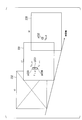
- FIG. 5 is a diagram for explaining processing of the interframe noise reduction unit 30.
- a frame image at time t3, a frame image at time t2, a frame image at time t1, and a frame image at time t0 are shown in order along the time axis.
- the luminance values (Y t3 , Y t2 , Y t1 , Y t0 , respectively) of pixels (p51, p52, p53, p54) having the same relative position in the image are shown.
- the process s56 of the noise reduction part 32 in the case where it did is shown.
- the inter-frame noise reduction unit 30 of the first embodiment stores the comparison result by the common comparison process in the magnitude relation storage unit 33 as information indicating the magnitude relation. Thereby, the inter-frame noise reduction unit 30 can reduce the frame memory that stores the pixel value data of the frame immediately before the target frame.
- the magnitude relationship storage is performed.
- the capacity of the unit 33 may be a quarter of that of the frame memory 331_2.
- the total amount of memory included in the inter-frame noise reduction unit 30 can be reduced from two frame memories to 1.25, and the memory capacity can be reduced (about 35% in this example).
- the noise reduction unit 32 determines the luminance value Y t2 of the pixel p52 and the luminance value of the pixel corresponding to the position of the pixel p52 in the preceding and following frames ( Y t3 , Y t1 ). The noise reduction unit 32, if the maximum luminance value Y t2 of the pixel p52 are subtracts the noise amount ⁇ from the luminance value Y t2, if minimum, adds the noise amount ⁇ to the luminance value Y t2.
- the noise reduction unit 32 causes the magnitude relationship storage unit 33 to store information indicating the magnitude relationship between the luminance value Y t2 of the pixel p52 and the luminance value Y t1 of the pixel p53.
- the noise reduction unit 32 displays information indicating the magnitude relationship between the luminance value Y t2 of the pixel p52 and the luminance value Y t1 of the pixel p53. Read from the magnitude relationship storage unit 33.
- the noise reduction unit 32 does not need to calculate again the magnitude relationship between the luminance value Y t2 of the pixel p52 and the luminance value Y t1 of the pixel p53, and the luminance value Y t1 of the pixel p53 that is the target pixel can be calculated. Only the luminance value Y t0 of the pixel p54 in the next frame may be compared.
- the noise reduction unit 32 does not need to refer to the luminance value Y t2 of the pixel p52 of the previous frame, so that the frame memory in which the pixel value of the previous frame used in the past is stored is stored. Can be reduced.
- the frame memory 31 stores raster-scanned image data supplied from the noise amount detection unit 20 for one frame.
- the magnitude relation storage unit 33 stores the magnitude relation between the pixel value of the pixel corresponding to the position of the pixel to be noise-reduced included in the target frame and the pixel value of the target pixel in the image one frame before. Information to be stored is stored.
- the noise reduction unit 32 receives the raster-scanned image data supplied from the noise amount detection unit 20 as information indicating the pixel value of the pixel after one frame corresponding to the position of the target pixel. In parallel with this, the noise reduction unit 32 reads information indicating the pixel value of the target pixel of the target frame from the frame memory 31. The noise reduction unit 32 also receives information indicating the magnitude relationship between the pixel value of the pixel at the position corresponding to the position of the target pixel and the pixel value of the target pixel in the image one frame before from the magnitude relationship storage unit 33 (for example, , Large, small, 2-bit data indicating the same).
- the noise reduction unit 32 determines the pixel value of the target pixel based on the pixel value of the target pixel of the target frame, the pixel value of the pixel after one frame corresponding to the position of the target pixel, and the information indicating the magnitude relationship. It is determined whether the pixel value is the maximum or the minimum among the pixel values of three pixels (the target pixel, the pixel after one frame corresponding to the position of the target pixel, and the pixel before one frame corresponding to the position of the target pixel).
- the noise reduction unit 32 has a magnitude relationship between the pixel value of the target pixel of the target frame and the pixel value of the pixel at the position corresponding to the position of the target pixel in the image after one frame (for example, large, small, or the same). To extract.
- the noise reduction unit 32 subtracts the noise amount ⁇ supplied from the noise amount detection unit 20 from the pixel value of the target pixel.
- the pixel value of the target pixel is the smallest among the pixel values of the above three pixels (the target pixel, the pixel after one frame corresponding to the position of the target pixel, and the pixel before one frame corresponding to the position of the target pixel).
- the noise reduction unit 32 adds the noise amount ⁇ supplied from the noise amount detection unit 20 from the pixel value of the target pixel.
- the noise reduction unit 32 supplies the horizontal noise reduction unit 40 with information indicating the pixel value after the above processing.
- the noise reduction unit 32 obtains information indicating the magnitude relationship between the pixel value of the pixel corresponding to the position of the target pixel stored in the magnitude relationship storage unit 33 and the pixel value of the target pixel, and the target pixel of the target frame. And information indicating the magnitude relationship between the pixel value of the pixel at the position corresponding to the position of the target pixel in the image after one frame (for example, 2-bit data indicating large, small, or the same) is overwritten.
- the noise reduction unit 32 reads the image data after one frame from the frame memory 31.
- the present invention is not limited to this, and the image signal after a predetermined number of frames is read from the frame memory 31. You may make it read from.
- image data after a predetermined number of frames from the target frame is stored by the noise amount detection unit 20.
- FIG. 6 is a functional block diagram of the horizontal noise reduction unit 40 in the first embodiment.
- the horizontal noise reduction unit 40 includes 2n dot memories 41_i (i is an integer from 0 to 2n) composed of dot memories 41_0,..., 41_n,. And a reduction unit 42.
- the dot memory 41_0 stores information indicating the pixel value supplied from the inter-frame noise reduction unit 30 for one pixel.
- the dot memory 41_0 supplies information indicating the stored pixel value for one pixel to the next dot memory 41_1 and the noise reduction unit 42 every time a predetermined time elapses. In parallel with this, the dot memory 41_0 overwrites the information indicating the stored pixel value with the information indicating the next pixel value supplied from the inter-frame noise reduction unit 30.
- the dot memory 41_i (here, i is an integer from 1 to n-1) stores information indicating the pixel value supplied from the dot memory 41_i-1 for one pixel.
- the dot memory 41_i supplies information indicating the stored pixel value for one pixel to the next dot memory 41_i + 1 every time a predetermined time elapses. In parallel with this, the dot memory 41_i overwrites the information indicating the stored pixel value with the information indicating the next pixel value supplied from the dot memory 41_i-1.
- the dot memory 41_n stores one pixel of information indicating the pixel value supplied from the dot memory 41_n-1.
- the dot memory 41_n supplies information indicating the stored pixel value for one pixel to the next dot memory 41_n + 1 and the noise reduction unit 42 every time a predetermined time elapses. In parallel with this, the dot memory 41_n overwrites the information indicating the stored pixel value with the information indicating the next pixel value supplied from the dot memory 41_n-1.
- the dot memory 41 — i (here, i is an integer from n + 1 to 2n ⁇ 1) stores information indicating the pixel value supplied from the dot memory 41 — i ⁇ 1 for one pixel.
- the dot memory 41_i supplies information indicating the stored pixel value for one pixel to the next dot memory 41_i + 1 every time a predetermined time elapses. In parallel with this, the dot memory 41_i overwrites the information indicating the stored pixel value with the information indicating the next pixel value supplied from the dot memory 41_i-1.
- the dot memory 41_2n stores information indicating the pixel value supplied from the dot memory 41_2n-1 for one pixel.
- the dot memory 41_2n supplies information indicating the stored pixel value for one pixel to the noise reduction unit 42 every time a predetermined time elapses. In parallel, the dot memory 41_2n overwrites the information indicating the stored pixel value with the information indicating the next pixel value supplied from the dot memory 41_2n-1.
- the noise reduction unit 42 receives information indicating the pixel value for one pixel supplied from the dot memory 41_0. In parallel, the noise reduction unit 42 receives information indicating the pixel value for one pixel supplied from the dot memory 41_n and information indicating the pixel value for one pixel supplied from the dot memory 41_2n. In addition, the noise reduction unit 42 receives information indicating the noise amount ⁇ from the noise amount detection unit 20.
- the noise reduction unit 42 compares the received pixel values for the one pixel. If the pixel value for one pixel supplied from the dot memory 41_n is the maximum among the three pixel values for one pixel, the noise reduction unit 42 calculates the pixel value for one pixel supplied from the dot memory 41_n. The noise amount ⁇ supplied from the noise amount detection unit 20 is subtracted. Then, the noise reduction unit 42 outputs information indicating the pixel value after subtraction to the vertical noise reduction unit 50.
- the noise reduction unit 42 supplies the pixel for one pixel supplied from the dot memory 41_n.
- the noise amount ⁇ supplied from the noise amount detection unit 20 is added to the value.
- the noise reduction unit 42 outputs information indicating the pixel value after addition to the vertical noise reduction unit 50.
- the noise reduction unit 42 if the pixel value for one pixel supplied from the dot memory 41_n among the three pixel values for the one pixel is a median value, the noise reduction unit 42 corresponds to one pixel supplied from the dot memory 41_n. Information indicating the pixel value is output to the vertical noise reduction unit 50.
- the pixel value for one pixel supplied from the dot memory 41_n is the pixel value of the target pixel that is the target of noise reduction
- the pixel value for one pixel supplied from the inter-frame noise reduction unit 30 is This corresponds to the pixel value of a pixel that is n pixels away to the right in the horizontal direction in the image.
- the pixel value for one pixel supplied from the dot memory 41_2n corresponds to a pixel that is n pixels away to the left in the horizontal direction.
- the noise reduction unit 42 is between the target pixel, the pixel that is n pixels away to the left from the target pixel in the image, and the pixel that is n pixels to the right from the target pixel in the image. Pixel values can be compared. And the noise reduction part 42 can reduce the noise superimposed on the horizontal direction within the flame
- FIG. 7 is a functional block diagram of the vertical noise reduction unit 50 in the first embodiment.
- the vertical noise reduction unit 50 includes 2m line memories 51_j (j is an integer from 0 to 2m) composed of line memories 51_0, ..., 51_m, ..., 51_2m (m is a positive integer), noise And a reduction unit 52.
- the line memory 51_0 sequentially stores information indicating pixel values sequentially supplied from the horizontal noise reduction unit 40.
- the line memory 51_0 stores information indicating the pixel value of the number of pixels corresponding to one line of the image
- information indicating the pixel value of one pixel stored at the earliest time among the information indicating the stored pixel value is supplied to the line memory 51_1 and the noise reduction unit 52.
- the line memory 51_0 overwrites the information indicating the pixel value stored at the earliest time among the information indicating the pixel value stored with the information indicating the pixel value supplied from the horizontal noise reduction unit 40.
- the line memory 51_j (where j is an integer from 1 to m ⁇ 1) sequentially stores information indicating pixel values sequentially supplied from the line memory 51_j ⁇ 1.
- the line memory 51_j stores information indicating the pixel value of the number of pixels corresponding to one line of the image
- information indicating the pixel value for one pixel stored at the earliest time among the information indicating the stored pixel value is supplied to the line memory 51_j + 1.
- the line memory 51_j overwrites the information indicating the pixel value stored at the earliest time among the information indicating the pixel value stored with the information indicating the pixel value supplied from the line memory 51_j-1.
- the line memory 51_m sequentially stores information indicating pixel values sequentially supplied from the line memory 51_m-1.
- the line memory 51_m stores information indicating the pixel value of the number of pixels corresponding to one line of the image
- information indicating the pixel value for one pixel stored at the earliest time among the information indicating the stored pixel value is supplied to the line memory 51_m + 1 and the noise reduction unit 52.
- the line memory 51_m overwrites the information indicating the pixel value stored at the earliest time among the information indicating the pixel value stored with the information indicating the pixel value supplied from the line memory 51_m-1.
- the line memory 51_j (where j is an integer from m + 1 to 2m ⁇ 1) sequentially receives information indicating pixel values sequentially supplied from the line memory 51_j ⁇ 1, and receives the information indicating the received pixel values as 1 of the image.
- the pixel corresponding to the line is stored.
- the line memory 51_j stores pixels corresponding to one line of the image
- the line memory 51_j is stored in parallel with the information indicating the pixel value for one pixel supplied from the line memory 51_j-1.
- the information indicating the pixel value for one pixel stored at the earliest time among the information indicating the existing pixel value is supplied to the line memory 51_j + 1.
- the line memory 51_j overwrites the information indicating the pixel value stored at the earliest time among the information indicating the pixel value stored with the information indicating the pixel value supplied from the line memory 51_j-1.
- the line memory 51_2m sequentially stores information indicating pixel values sequentially supplied from the line memory 51_2m-1.
- the line memory 51_2m stores information indicating the pixel value of the number of pixels corresponding to one line of the image
- information indicating the pixel value for one pixel stored at the earliest time among the information indicating the stored pixel value is supplied to the noise reduction unit 52.
- the line memory 51_2m overwrites the information indicating the pixel value stored at the earliest time among the information indicating the stored pixel value with the information indicating the pixel value supplied from the line memory 51_2m-1.
- the noise reduction unit 52 receives information indicating the pixel value for one pixel supplied from the line memory 51_0. In parallel, the noise reduction unit 52 receives information indicating the pixel value for one pixel supplied from the line memory 51_m and information indicating the pixel value for one pixel supplied from the line memory 51_2m. Further, the noise reduction unit 52 receives information indicating the noise amount ⁇ from the noise amount detection unit 20.
- the noise reduction unit 52 compares the received pixel values for the one pixel. If the pixel value for one pixel supplied from the line memory 51_m is the maximum among the three pixel values for one pixel, the noise reduction unit 52 calculates the pixel value for one pixel supplied from the line memory 51_m. The noise amount ⁇ supplied from the noise amount detection unit 20 is subtracted. Then, the noise reduction unit 52 outputs information indicating the pixel value after the subtraction to the image format conversion unit 14.
- the noise reduction unit 52 supplies the pixels for one pixel supplied from the line memory 51_m.
- the noise amount ⁇ supplied from the noise amount detection unit 20 is added to the value.
- the noise reduction unit 52 then outputs information indicating the pixel value after the addition to the image format conversion unit 14.
- the noise reduction unit 52 if the pixel value for one pixel supplied from the line memory 51_m among the three pixel values for the one pixel is a median value, the noise reduction unit 52 corresponds to one pixel supplied from the line memory 51_m. Information indicating the pixel value is output to the image format converter 14.
- the pixel value for one pixel supplied from the line memory 51_m is used as the pixel value of the target pixel to be subjected to noise reduction
- the pixel value for one pixel supplied from the horizontal noise reduction unit 40 is This corresponds to the pixel value of a pixel that is m pixels below the target pixel.
- the pixel value for m pixels supplied from the line memory 51_2m corresponds to a pixel value of a pixel that is m pixels away from the target pixel in the image.
- the noise reduction unit 52 compares the pixel values between the target pixel, a pixel that is m pixels above the target pixel in the image, and a pixel that is m pixels below the target pixel in the image. can do. And the noise reduction part 52 can reduce the noise superimposed on the perpendicular direction within the flame
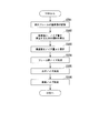
- FIG. 8 is a flowchart showing the flow of processing of the display device 1 in the first embodiment.
- the detection unit 11 is supplied with a broadcast wave signal received from the antenna 10 and outputs the supplied signal to the Y / C separation unit 12.
- the Y / C separation unit 12 demodulates the signal supplied from the detection unit 11, performs Y / C separation, performs A / D conversion, and performs image data (luminance data Y after the A / D conversion).
- Color difference data Cb, color difference data Cr is output to the image processing unit 20 (step S101).
- the noise reduction processing unit 13 performs noise reduction processing on the image data supplied from the Y / C separation unit 12 (step S102).
- the image format conversion unit 14 displays video generated for an I (Interlace) / P (Progressive) conversion (interlace video device) in a progressive format from the image signal subjected to the noise reduction processing.
- the image format converter 14 converts the I / P converted image signal into an RGB signal (red, green, and blue gradation data) (step S103).
- the liquid crystal driving unit 15 generates a clock signal for writing the supplied RGB signals to the liquid crystal elements PIX arranged in a matrix in the liquid crystal panel 16 (step S104).
- the liquid crystal driving unit 15 converts the gradation data in the RGB signal into a gradation voltage for performing liquid crystal driving (step S105).
- the liquid crystal driver 15 holds the gradation voltage for each source line in the liquid crystal panel 16 by an internal hold circuit.
- the liquid crystal driver 15 supplies a predetermined voltage to one of the gate lines in the liquid crystal panel 16, and applies the predetermined voltage to the gate electrode of the TFT of the liquid crystal element (step) S106).
- the liquid crystal driving unit 15 supplies a gradation voltage that is held for each source line in the liquid crystal panel 16 (step S107).
- the gradation voltage is sequentially supplied to the source line within the time when each gate line is selected, and the gradation voltage (gradation degree data) necessary for display is turned on. Data is written to the pixel element connected to the drain of the TFT in the state. As a result, the pixel element changes the transmittance by controlling the orientation of the internal liquid crystal according to the applied gradation voltage. As a result, the video signal received by the detector 11 is displayed on the liquid crystal panel 16 (step S108). Above, the process of the flowchart of FIG. 8 is complete
- FIG. 9 is a flowchart showing details of the processing of the noise reduction processing unit 13 in step S102 of FIG.
- the noise amount detection unit 20 detects the noise amount from the image data input from the Y / C separation unit 12 (step S201).
- the frame memory 31 of the inter-frame noise reduction unit 30 stores information indicating the pixel value of the target frame including the target pixel that is the target of noise reduction (step S202).
- the noise reduction unit 32 refers to information indicating the magnitude relationship between the pixel value of the target pixel stored in the magnitude relationship storage unit 33 and the pixel value of the pixel of the previous frame corresponding to the position of the target pixel. (Step S203). Next, the noise reduction unit 32 compares the pixel value of the target pixel read from the frame memory 31 with the pixel value of the pixel at the position corresponding to the position of the target pixel in the next frame, and the comparison result and reference Noise is reduced based on the information indicating the magnitude relationship that has been made (step S204).
- the noise reduction unit 32 stores information indicating the comparison result in the magnitude relation storage unit 33 (step S205).
- the horizontal noise reduction unit 40 reduces the horizontal noise superimposed in the horizontal direction of the image on the image data after the inter-frame noise reduction (step S206).
- the vertical noise reduction unit 50 reduces the vertical noise superimposed in the vertical direction of the image on the image data after the interframe noise reduction (step S207).
- the process of the flowchart of FIG. 9 is complete
- the processes of steps S202, S203, S204, and S205 are processes of the interframe noise reduction unit 30.
- the noise reduction unit 32 includes the pixel value of the target pixel stored in the magnitude relation storage unit 33 and the previous frame corresponding to the position of the target pixel.
- Information indicating the magnitude relationship between pixel values of pixels is referred to, and noise between frames is reduced based on the information indicating the referenced magnitude relationship.
- the noise reduction processing unit 13 of the first embodiment can reduce the frame memory that stores the pixel value of the pixel of the immediately previous frame, which has been conventionally required, and the magnitude relation storage unit 33. Requires less memory capacity than the frame memory, the total memory capacity of the noise reduction processing unit 13 can be reduced. As a result, the noise reduction processing unit 13 can reduce the production cost of the noise reduction processing unit 13.
- the noise reduction processing unit 13 compares the pixel values between the target pixel and the pixels of the frame around one frame.
- the present invention is not limited to this, and the noise reduction processing unit 13 does not limit the pixel value between the target pixel and the pixels around the predetermined number of frames. Pixel values may be compared.
- FIG. 10 is a schematic block diagram of the display device 2 according to the second embodiment.
- symbol is attached
- the noise reduction processing unit 13 is changed to a noise reduction processing unit 13 b with respect to the configuration of the display device 1 in FIG. 1.
- FIG. 11 is a schematic block diagram of the noise reduction processing unit 13b in the second embodiment.
- symbol is attached
- the vertical noise reduction unit 50 is changed to the vertical noise reduction unit 50b with respect to the configuration of the noise reduction processing unit 13 in FIG.
- FIG. 12 is a functional block diagram of the vertical noise reduction unit 50b in the second embodiment.
- symbol is attached
- the configuration of the vertical noise reduction unit 50b in FIG. 12 is different from the configuration of the vertical noise reduction unit 50 in FIG. 7 in that m line memories up to line memories 51_m + 1,.
- the line memory 51b_m is changed, the noise reduction unit 52 is changed to the noise reduction unit 52b, and a magnitude relation storage unit 53 is added.
- the vertical noise reduction unit 50b includes m line memories 51_i (i is an integer from 0 to m) up to line memories 51_0,..., 51_m ⁇ 1 (m is a positive integer), and line memories 51b_m. And a noise reduction unit 52b and a magnitude relation storage unit 53.
- the line memory 51b_m sequentially receives information indicating the pixel values supplied from the line memory 51b_m-1, and stores the received information indicating the pixel values for the number of pixels corresponding to one line of the image.
- the line memory 51b_m stores pixel values for pixels corresponding to one line of the image
- every time information indicating the pixel values for one pixel supplied from the line memory 51b_m-1 is supplied,
- the information indicating the pixel value for one pixel stored at the earliest time among the information indicating the pixel value stored is used as the information indicating the pixel value of the target pixel that is the target of noise reduction. Supply.
- the line memory 51b_m overwrites the information indicating the pixel value stored at the earliest time among the information indicating the stored pixel value with the information indicating the pixel value supplied from the line memory 51b_m-1.
- the magnitude relation storage unit 53 information indicating the magnitude relation of pixel values between a predetermined pixel and a pixel that is m pixels above the predetermined pixel is stored for m lines above the line including the target pixel. ing.
- the noise reduction unit 52b reads information indicating the magnitude relationship of pixel values between the target pixel and a pixel that is m pixels above the target pixel from the magnitude relation storage unit 53.
- the noise reduction unit 52b uses the information indicating the pixel value for one pixel supplied from the line memory 51_0 as the information indicating the pixel value of the pixel that is m pixels below the target pixel, for each pixel. receive. In parallel with this, the noise reduction unit 52b receives information indicating the pixel value of the target pixel supplied from the line memory 51b_m. In addition, the noise reduction unit 52 b receives information indicating the noise amount ⁇ from the noise amount detection unit 20.
- the noise reduction unit 52b compares the pixel value of the target pixel, the pixel value of the pixel that is m pixels below the target pixel, and the pixel value between the target pixel and the pixel that is m pixels above the target pixel. And noise is reduced based on the noise amount ⁇ .
- the noise reduction unit 52b receives information indicating the pixel values for the three pixels, the pixel value of the target pixel and the pixel value of a pixel that is m pixels below the target pixel And the magnitude relationship of the pixel values between the target pixel and the pixel that is m pixels above the target pixel, the target pixel is the target pixel, the pixel that is m pixels below the target pixel, and the target pixel It is determined whether it is the maximum or the minimum among the pixels separated by m pixels.
- the noise reduction unit 52b extracts a magnitude relationship (large, small, or the same) of pixel values between the target pixel and a pixel that is m pixels below the target pixel.
- the noise reduction unit 52b subtracts the noise amount ⁇ supplied from the noise amount detection unit 20 from the pixel value of the target pixel.
- the noise reduction unit 52 b outputs information indicating the pixel value after subtraction to the image format conversion unit 14.
- the noise reduction unit 52b adds the noise amount ⁇ supplied from the noise amount detection unit 20 to the pixel value of the target pixel.
- the noise reduction unit 52b outputs information indicating the pixel value after the addition to the image format conversion unit 14. Further, if the pixel value of the target pixel is the median value, the noise reduction unit 52b outputs information indicating the pixel value of the target pixel to the image format conversion unit 14.
- the noise reduction unit 52b obtains information indicating the magnitude relationship of pixel values between the target pixel stored in the magnitude relation storage unit 53 and a pixel that is m pixels above the target pixel, from the target pixel and the target pixel.
- the information is overwritten with information indicating the magnitude relationship of pixel values with pixels separated by m pixels below (for example, 2-bit data indicating large, small, or the same).
- FIG. 13 is a diagram for explaining the intra-frame processing in the vertical direction of the noise reduction unit 52b in the second embodiment.
- an image 130 of one frame is shown.
- a pixel p132, a pixel p131 that is m pixels above the pixel p132, a pixel p133 that is m pixels below the pixel p132, and a pixel p134 that is m pixels below the pixel p133 are shown. Yes.
- the luminance value of the pixel p131 is Y j ⁇ m
- the luminance value of the pixel p132 is Y j
- the luminance value of the pixel p133 is Y j + m
- the luminance value of the pixel p134 is Y j + 2m . .
- the noise reduction unit 52b performs a process s131 surrounded by a square. That is, the noise reduction unit 52b subtracts the noise amount ⁇ from the luminance value Y j when (Y j > Y j ⁇ m ) and (Y j > Y j + m ). The noise reduction unit 52b adds the noise amount ⁇ to the luminance value Y j when (Y j ⁇ Y j ⁇ m ) and (Y j ⁇ Y j + m ).
- the noise reduction unit 52b performs a process s133 enclosed by a square. That is, the noise reduction unit 52b subtracts the noise amount ⁇ from the luminance value Y j + m when (Y j + m > Y j ) and (Y j + m > Y j + 2m ). The noise reduction unit 52b adds the noise amount ⁇ to the luminance value Y j + m when (Y j + m ⁇ Y j ) and (Y j + m ⁇ Y j + 2m ).
- the comparison processing between the luminance value Y j + m of the luminance values Y j and the pixel p133 in the pixel p132 in treatment s132, the process of comparison between a luminance value Y j + m of the luminance values Y j and the pixel p133 in the pixel p132 in treatment s134 Indicates that the processing is common.
- the noise reduction unit 52b of the second embodiment stores information indicating the magnitude relationship obtained by the common comparison process in the magnitude relationship storage unit 53. Thereby, the noise reduction part 52b can reduce the line memory which stores the information which shows the pixel value on m line rather than the line containing an object pixel.
- the line memory for storing pixel values for m lines from the line memories 51_m + 1 to 51_2m shown in FIG. 7 is reduced, and a memory for storing the magnitude relationship for m lines is added to the magnitude relation storage unit 53.
- the capacity of 53 is a quarter of the total capacity of the line memories 51_m + 1 to 51_2m.
- FIG. 14 is a flowchart showing details of the processing of the noise reduction processing unit 13b in step S102 of FIG. 8 in the second embodiment.
- the noise amount detection unit 20 detects the noise amount ⁇ from the image data input from the Y / C separation unit 12 (step S301).
- the interframe noise reduction unit 30 reduces interframe noise (step S302).
- the horizontal noise reduction unit 40 reduces the horizontal noise superimposed in the horizontal direction of the image on the image data after the inter-frame noise reduction (step S303).
- the vertical noise reduction unit 50b stores information indicating pixel values from the target line including the target pixel to the m ⁇ 1th line down from the target line in each of the line memories 51_1 to 51b_m (Step S304). .
- the noise reduction unit 52b refers to the magnitude relation storage unit 53, and refers to information indicating the magnitude relation between the target pixel and a pixel that is m pixels above the target pixel (step S305).
- the noise reduction unit 52b indicates information indicating the pixel value of the target pixel, information indicating the pixel value of a pixel that is m pixels below the target pixel, information indicating the magnitude relationship that has been referenced, and the amount of noise. Based on the information, the vertical noise superimposed in the vertical direction on the target pixel is reduced (step S306).
- the noise reduction unit 52b causes the magnitude relationship storage unit 53 to store information indicating the magnitude relationship between the target pixel and a pixel that is m pixels below the target pixel (step S307).
- the process of the flowchart in FIG. 14 ends.
- the processes of steps S304, S305, S306, and S307 are processes of the vertical noise reduction unit 50b.
- the noise reduction processing unit 13b stores the two comparison pixels to be compared with the target pixel at positions symmetrical to the target pixel in the vertical direction, thereby being stored in the magnitude relation storage unit 53.
- the noise reduction process part 13b reduces the noise superimposed on the orthogonal
- the noise reduction processing unit 13b in the second embodiment has the following effects in addition to the memory capacity reduction effect by the inter-frame noise reduction unit 30 described in the first embodiment.
- the noise reduction processing unit 13b can reduce a predetermined number of line memories that have been conventionally required, and the size relationship storage unit 53 requires less memory capacity than the line memory, so the noise reduction processing unit The total capacity of the memory provided in 13b can be reduced. As a result, the noise reduction processing unit 13b can reduce the production cost of the noise reduction processing unit 13b.
- FIG. 15 is a schematic block diagram of the display device 3 according to the third embodiment.
- symbol is attached
- the noise reduction processing unit 13 is changed to a noise reduction processing unit 13 c with respect to the configuration of the display device 1 in FIG. 1.
- FIG. 16 is a schematic block diagram of the noise reduction processing unit 13c in the third embodiment.
- symbol is attached
- the horizontal noise reduction unit 40 is changed to the horizontal noise reduction unit 40c with respect to the configuration of the noise reduction processing unit 13 in FIG.
- FIG. 17 is a functional block diagram of the horizontal noise reduction unit 40c in the third embodiment.
- symbol is attached
- the configuration of the horizontal noise reduction unit 40c in FIG. 17 is different from the configuration of the horizontal noise reduction unit 40 in FIG. 6 in that n dot memories up to dot memories 41_n + 1,.
- the dot memory 41c_n is changed, the noise reduction unit 42 is changed to the noise reduction unit 42c, and a magnitude relation storage unit 43 is added.
- the dot memory 41c_n stores information indicating the pixel value supplied from the dot memory 41_n-1 for one pixel.
- the dot memory 41c_n supplies the stored information indicating the pixel value for one pixel to the noise reduction unit 42c as information indicating the pixel value of the target pixel that is the target of noise reduction every time a predetermined time elapses.
- the dot memory 41c_n overwrites the information indicating the stored pixel value with the information indicating the next pixel value supplied from the dot memory 41_n-1.
- the magnitude relationship storage unit 43 stores information indicating the magnitude relationship of pixel values between a predetermined pixel and a pixel that is n pixels to the left from the predetermined pixel, and the predetermined pixel moves from the target pixel toward the target pixel. Only the amount up to n-1 pixels is stored on the left.
- the noise reduction unit 42c reads information indicating the magnitude relationship of pixel values between the target pixel and a pixel that is n pixels away from the target pixel to the right from the magnitude relationship storage unit 43.
- the noise reduction unit 42c uses the information indicating the pixel value for one pixel supplied from the dot memory 41_0 as information indicating the pixel value of the pixel that is n pixels away from the target pixel to the right. Receive every minute. In parallel with this, the noise reduction unit 42c receives information indicating the pixel value of the target pixel supplied from the dot memory 41c_n. In addition, the noise reduction unit 42 c receives information indicating the noise amount ⁇ from the noise amount detection unit 20.
- the noise reduction unit 42c is a pixel between the pixel value of the target pixel, the pixel value of the pixel that is n pixels to the right from the target pixel, and the pixel that is n pixels to the left from the target pixel. Noise is reduced based on the magnitude relationship between the values and the noise amount ⁇ .
- the noise reduction unit 42c each time the noise reduction unit 42c receives information indicating the pixel values of the three pixels, the noise reduction unit 42c and the pixel value of the target pixel and the pixel n pixels away from the target pixel to the right are displayed. Based on the pixel value and the magnitude relationship of the pixel value between the target pixel and the pixel that is n pixels left from the target pixel, the target pixel is n pixels left from the target pixel and the target pixel It is determined whether it is the maximum or the minimum among the pixels that are n pixels to the right from the pixel and the target pixel. At that time, the noise reduction unit 42c extracts a magnitude relationship (large, small, or the same) of pixel values between the target pixel and a pixel that is n pixels to the right from the target pixel.
- the noise reduction unit 42c subtracts the noise amount ⁇ supplied from the noise amount ⁇ detection unit 20 from the pixel value of the target pixel.
- the noise reduction unit 42 c outputs information indicating the pixel value after subtraction to the image format conversion unit 14.
- the noise reduction unit 42c adds the noise amount ⁇ supplied from the noise amount ⁇ detection unit 20 to the pixel value of the target pixel.
- the noise reduction unit 42 c outputs information indicating the pixel value after the addition to the image format conversion unit 14.
- the noise reduction unit 42c outputs information indicating the pixel value of the target pixel to the image format conversion unit 14.
- the noise reduction unit 42c obtains information indicating the magnitude relationship of pixel values between the target pixel stored in the magnitude relationship storage unit 53 and a pixel that is n pixels away from the target pixel to the left. Overwriting is performed with information indicating the magnitude relationship of pixel values with pixels that are n pixels away from the pixel to the right (for example, 2-bit data indicating large, small, or the same).
- FIG. 18 is a diagram for explaining the intra-frame processing in the horizontal direction of the noise reduction unit 42c according to the third embodiment.
- an image 180 of one frame is shown.
- a pixel p182 a pixel p181 that is n pixels to the left from the pixel p182, a pixel p183 that is n pixels to the right from the pixel p182, and a pixel that is n pixels to the right from the pixel p183 p184 is shown.
- the luminance value of the pixel p181 is Y i ⁇ n
- the luminance value of the pixel p182 is Y i
- the luminance value of the pixel p183 is Y i + n
- the luminance value of the pixel p184 is Y i + 2n . .
- the noise reduction unit 42c performs a process s181 surrounded by a square. That is, the noise reduction unit 42c subtracts the noise amount ⁇ from the luminance value Y i when (Y i > Y i ⁇ n ) and (Y i > Y i + n ). The noise reduction unit 42c adds the noise amount ⁇ to the luminance value Y i when (Y i ⁇ Y i ⁇ n ) and (Y i ⁇ Y i + n ).
- the noise reduction unit 42c performs a process s183 surrounded by a square. That is, the noise reduction unit 42c subtracts the noise amount ⁇ from the luminance value Y i + n when (Y i + n > Y i ) and (Y i + n > Y i + 2n ). The noise reduction unit 42c adds the noise amount ⁇ to the luminance value Y i + n when (Y i + n ⁇ Y i ) and (Y i + n ⁇ Y i + 2n ).
- the comparison processing between the luminance value Y i + n of luminance values Y i and the pixel p183 in the pixel p182 in treatment s 182, and comparison process between the luminance value Y i + n of luminance values Y i and the pixel p183 in the pixel p182 in treatment s184 Indicates that the processing is common.
- the dot memory for storing the pixel values for n pixels from the dot memories 41_n + 1 to 41_2n shown in FIG. 6 is reduced, and a memory for storing the size relationship for n pixels is added to the size relationship storage unit 43.
- the magnitude relation storage section The capacity of 43 is a quarter of the total capacity of the dot memories 41_n + 1 to 41_2n.
- the overall processing flow of the display device 3 according to the third embodiment is the same as the overall processing flow of the display device 1 according to the first embodiment shown in FIG.
- FIG. 19 is a flowchart showing details of the processing of the noise reduction processing unit 13c in step S102 of FIG. 8 in the third embodiment.
- the noise amount detection unit 20 detects the noise amount ⁇ from the image data input from the Y / C separation unit 12 (step S401).
- the interframe noise reduction unit 30 reduces interframe noise (step S302).
- the horizontal noise reduction unit 40c stores information indicating pixel values from the target pixel to the pixel that is n-1 pixels to the right from the target pixel in each dot memory 41_n to 41_1 (step S403).
- the magnitude relation storage unit 42 is referred to, and information indicating the magnitude relation between the target pixel and a pixel that is n pixels away from the target pixel to the left is referenced (step S404).
- the horizontal noise reduction unit 40c includes information indicating the pixel value of the target pixel, information indicating the pixel value of the pixel that is n pixels to the right from the target pixel, information indicating the magnitude relationship that has been referred to, and noise Based on the information indicating the amount, the horizontal noise superimposed on the target pixel in the horizontal direction is reduced (step S405).
- the horizontal noise reduction unit 40c causes the magnitude relation storage unit 43 to store information indicating the magnitude relation between the target pixel and the pixel that is n pixels away from the target pixel to the right (step S406).
- the vertical noise reduction unit 50 reduces the vertical noise superimposed in the vertical direction on the target pixel (step S407).
- the process of the flowchart of FIG. 19 is complete
- the processes of steps S403, S404, S405, and S406 are processes of the horizontal noise reduction unit 40c.
- the noise reduction processing unit 13c stores the two comparison pixels to be compared with the target pixel at positions symmetrical with respect to the target pixel in the horizontal direction, thereby being stored in the magnitude relation storage unit 43.
- the horizontal reference is superimposed on the target pixel in the horizontal direction based on the information indicating the magnitude relationship between the target pixel and the pixel that is a predetermined number of pixels left from the target pixel. Reduce noise.
- the noise reduction processing unit 13c in the third embodiment has the following effects in addition to the memory capacity reduction effect by the interframe noise reduction unit 30 described in the first embodiment.
- the noise reduction processing unit 13c can reduce a predetermined number of dot memories that are conventionally required, and the memory capacity required by the magnitude relation storage unit 43 is larger than the predetermined number of dot memories. Therefore, the total capacity of the memory included in the noise reduction processing unit 13c can be reduced. As a result, the noise reduction processing unit 13c can reduce the production cost of the noise reduction processing unit 13c.
- the noise reduction processing unit 13b of the second embodiment takes two comparison pixels to be compared with the target pixel at positions symmetrical to the target pixel in the vertical direction, and the noise reduction processing unit 13c of the third embodiment
- the two comparison pixels to be compared with the target pixel are positioned symmetrically with respect to the target pixel in the horizontal direction, the present invention is not limited to this.
- the noise reduction processing unit (13b, 13c) only needs to place two comparison pixels to be compared with the target pixel in a point-symmetrical position with respect to the target pixel.
- the two comparison pixels to be compared with the target pixel are used as the target pixel.
- the position may be symmetrical to the diagonal direction.
- the noise reduction process part (13b, 13c) can reduce the noise superimposed on the diagonal direction in the object pixel.
- a noise reduction process part (13, 13b, 13c) reduces noise between frames.
- the noise may be reduced by using at least one of the unit (30), the horizontal noise reduction unit (40c), and the vertical noise reduction unit (50b).
- the display devices (1, 2, 3) in the first to third embodiments detect the amount of noise from the vertical blanking period.
- the display device 4 according to the fourth embodiment estimates the amount of noise using an image of a detection target frame that is a target of noise amount detection and an image of a frame that is a predetermined number before the detection target frame.
- the display device 4 does not require a frame memory in which the pixel values of the image of a predetermined number of frames are stored when estimating the amount of noise. Signal), the amount of noise can be estimated while suppressing the capacity of the frame memory.
- FIG. 20 is a schematic block diagram of the display device 4 according to the fourth embodiment.
- symbol is attached
- the noise reduction processing unit 13 is changed to a noise reduction processing unit 13 d with respect to the configuration of the display device 1 in FIG. 1.
- FIG. 21 is a schematic block diagram of the noise reduction processing unit 13d according to the fourth embodiment.
- symbol is attached
- the noise amount detection unit 20 is changed to a noise amount detection unit 20d with respect to the configuration of the noise reduction processing unit 13 in FIG.
- FIG. 22 is a functional block diagram of the noise amount detection unit 20d according to the fourth embodiment.
- the noise amount detection unit 20 d includes a frame memory 21, a calculation unit 22, and a noise amount estimation unit 23.
- the frame memory 21 sequentially stores information indicating pixel values for one pixel subjected to raster scanning sequentially supplied from the Y / C separation unit 12.
- the frame memory 21 stores the information indicating the pixel value for one frame, each time the information indicating the pixel value for one pixel is supplied from the Y / C separation unit 12, the pixel value stored at the earliest time is stored. Information to be shown is supplied to the calculation unit 22.
- the calculation unit 22 sequentially receives information indicating pixel values for one pixel subjected to raster scanning supplied from the Y / C separation unit 12.
- the calculation unit 22 calculates the pixel value of the detection pixel, the pixel value of the pixel at the position corresponding to the position of the detection pixel in the image one frame before the image including the detection pixel, To estimate the amount of noise based on the pixel value of a pixel that is one pixel above the detection pixel in the image including the detection pixel and the pixel value of a pixel that is one pixel below the detection pixel Is calculated for each pixel in the image including the detected pixel.
- the calculating unit 22 outputs information indicating the value Nd for estimating the calculated noise amount to the noise amount estimating unit 23.
- the calculation unit 22 uses a pixel one pixel above and one pixel below the detection pixel. However, the calculation unit 22 uses a first interval from the detection pixel (the first interval is an integer of 1 or more). ) And pixels separated from the detection pixel by a second interval (the second interval is an integer equal to or greater than 1) may be used. In this case, the first interval and the second interval may be the same or different.
- the calculation unit 22 uses a pixel one frame before the frame including the detection pixel.
- the present invention is not limited to this, and pixels in a frame a predetermined number of frames before the frame including the detection pixel are used. It may be used.
- the calculation unit 22 uses a pixel one frame before the frame including the detection pixel.
- the calculation unit 22 is not limited thereto, and a predetermined number of frames (one or more frames) from the frame including the detection pixel. Only the pixels of the later frame may be used.
- the calculation unit 22 calculates the pixel value of the detection pixel that is a target for detecting the amount of noise included in the image, and the value in the image that is a predetermined number of frames before the image including the detection pixel.
- the pixel value of the previous frame pixel that is a pixel corresponding to the position of the detection pixel, the pixel value of the pixel that is separated from the detection pixel by the first interval in the image including the detection pixel, and the detection pixel from the detection pixel Based on the pixel values of pixels separated by an interval of 2, a value Nd for estimating the amount of noise is calculated for a predetermined pixel.
- FIG. 23 is a diagram for explaining the processing of the calculation unit 22 in the fourth embodiment.
- an image 232 of a frame at time t2 an image 231 of a frame at time t1, and an image 230 of a frame at time t0 are shown in order along the time axis.
- the detection pixel p231 that is a target for detecting the amount of noise in the image 231 of the frame at time t1 and the frame of the frame at time t0.
- a pixel p232 at a position corresponding to the position of the detection pixel p231, a pixel p233 one higher than the detection pixel p231, and a pixel p234 one lower than the detection pixel p231 are shown.
- the noise amount detection unit 20d in the fourth embodiment uses only one of the frame memories 21 and does not use the luminance value of the image 232 of the frame at time t2, the image 232 of the frame at time t2 has a large size. A cross is shown.
- the noise amount detection unit 20d cannot refer to information indicating the pixel value of the pixel at the position corresponding to the position of the detection pixel p231 in the frame at time t2. Instead, the noise amount detection unit 20d uses the pixel values of the pixels around the detection pixel p231 in the frame at time t1, and uses the pixel value Y of the pixel at the position corresponding to the position of the detection pixel p231 in the frame at time t2. Approximate t2_v0 .
- the display frequency of vertical pixels is closer to the frame frequency than the display frequency of horizontal pixels. Since the display frequency of the vertical pixel is closer to the frame frequency than the display frequency of the horizontal pixel, noise characteristics are close. Therefore, the calculation unit 22 uses pixels (p233 and p234) that are adjacent to the detection pixel p231 in the vertical direction. Thus, the pixel value Y t2_v0 of the pixel at the position corresponding to the position of the detection pixel p231 in the frame at time t2 is approximated.
- the calculation unit 22 determines that the average value (Y t1_v ⁇ 1 + Y t1_v + 1 ) / 2 of the pixel p233 and the pixel p234 that are adjacent to the detection pixel p231 in the vertical direction in the frame at time t2.
- the pixel value Yt2_v0 of the pixel at a position corresponding to the position of the detection pixel p231 is approximated. That is, the calculation unit 22 calculates a value Nd for estimating the amount of noise for each pixel in the detection target frame according to the following equation (1).
- Nd Abs (Y t1_v0 ⁇ ((Y t1_v ⁇ 1 + Y t1_v + 1 ) / 2 + Y t0_v0 ) / 2) (1)
- Abs is a function that returns the absolute value of the argument.
- the calculation unit 22 outputs information indicating a value Nd for estimating each noise amount calculated in each pixel to the noise amount estimation unit 23.
- the noise amount detection unit 20d in the fourth embodiment calculates the value Nd for estimating the noise amount using pixels adjacent to the detection pixel p231 in the vertical direction.
- a value Nd for estimating the amount of noise may be calculated using pixels adjacent to p231 in the horizontal direction.
- the noise amount estimation unit 23 estimates the noise amount included in the image based on the frequency of the value Nd for estimating the noise amount supplied from the calculation unit 22. More specifically, the noise amount estimation unit 23 estimates the mode value of the frequency of the value Nd for estimating the noise amount calculated by the calculation unit 22 as the noise amount included in the image.
- the noise amount estimation unit 23 counts the appearance frequency for each value Nd for estimating the noise amount supplied from the calculation unit 22, and estimates the noise amount when the appearance frequency becomes maximum.
- the mode value which is the value Nd for the purpose is extracted.
- the noise amount estimation unit 23 outputs the information indicating the extracted mode value to the inter-frame noise reduction unit 30, the horizontal noise reduction unit 40, and the vertical noise reduction unit 50 as information indicating the noise amount.
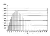
- FIG. 24 is an example of a histogram of the value Nd for estimating the noise amount.
- the vertical axis represents frequency, and the horizontal axis represents a value Nd for estimating the amount of noise.
- the appearance frequency of the value Nd for estimating the amount of noise in the detection target image of a certain frame is shown for each value Nd for estimating the amount of noise.
- the mode value is 10.
- the noise amount estimation unit 23 estimates the mode value as the noise amount ⁇ .
- FIG. 25 shows a luminance distribution when Gaussian noise with a standard deviation of 10 is added to an image having a luminance value 128 of all pixels.
- the luminance distribution w251 shows a Gaussian distribution with a peak having a luminance value of 128 and a standard deviation of 10. Since typical noise superimposed on video is Gaussian noise, the principle of the noise amount detection unit 20d will be described using a luminance distribution w251 to which Gaussian noise is added.
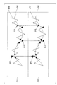
- FIG. 26 is a diagram showing an outline of noise reduction processing in the inter-frame noise reduction unit 30, the horizontal noise reduction unit 40, and the vertical noise reduction unit 50 according to the fourth embodiment.
- a curve w261 indicating the original pixel value
- a curve w262 indicating the pixel value on which noise is superimposed are shown.
- the input video Z11 is information indicating pixel values input to the respective parts (30, 40, 50) indicated by round, square, or triangular dots
- the output video Z12 is round, square, or triangular dots. This is information indicating the pixel value output from each unit (30, 40, 50) indicated by.
- each unit (30, 40, 50) when the pixel value at the middle time is the maximum among the three pixel values acquired at predetermined time intervals (reference C11 in FIG. 26), Subtracts the noise amount ⁇ from the intermediate pixel value (reference P11 in FIG. 26).
- each of the units (30, 40, 50) has a noise amount ⁇ in the middle pixel value of the time when the pixel value at the middle time is the smallest among the three pixel values (reference C12 in FIG. 26). Are added (reference P12 in FIG. 26).
- Each unit (30, 40, 50) performs addition / subtraction with respect to the pixel value at the intermediate time when the pixel value at the intermediate time among the three pixel values is the median value (reference symbol C13 in FIG. 26). No (P13 in FIG. 26).
- FIG. 27 is a diagram for explaining processing performed on image data indicating the luminance distribution w251 in FIG.
- a luminance value region R271 smaller than the luminance value 128 and a luminance value region R272 larger than the luminance value 128 are shown with the luminance value 128 as a boundary.
- Each part (30, 40, 50) tends to add the noise amount ⁇ to the pixel value belonging to the region R271 and subtract the noise amount ⁇ from the pixel value belonging to the region R272 in the image data indicating the luminance distribution w251 in FIG. It is in.
- FIG. 28 shows the frequency distribution of the luminance values after the noise reduction processing is performed for each noise amount.
- the luminance distribution w281 when the noise amount ⁇ is 5 and the noise is reduced the luminance distribution w282 when the noise amount ⁇ is 10 and the noise is reduced
- the noise amount A luminance distribution w283 when ⁇ is 20 and noise is reduced is shown.
- the luminance distribution w283 When the noise amount ⁇ is 20 and the noise is reduced, the luminance distribution w283 has a higher frequency at a luminance value that is 11 luminance values or more away from the luminance value 128 than the luminance distribution w251 before noise reduction.
- the distribution w283 indicates that the noise is higher than the luminance distribution w251 before noise reduction.
- FIG. 29 is a diagram showing the relationship between the noise amount ⁇ and the variance value of the pixel value.
- the vertical axis is the variance value of the pixel value
- the horizontal axis is the noise amount ⁇ .
- the variance value of the pixel value takes the minimum value V11
- the standard deviation of the Gaussian noise is 10
- the variance value of the pixel value takes a value V12 close to the minimum value. It is shown.
- the noise amount ⁇ when each part (30, 40, 50) performs noise reduction processing on an image given Gaussian noise with a standard deviation of 10 is a value smaller than the standard deviation of the noise by a predetermined number.
- the noise reduction effect is most obtained.
- FIG. 30A is a diagram for describing a method of calculating a histogram indicating the frequency for each value Nd ′ for estimating the amount of noise.
- FIG. 30B is a diagram showing a histogram showing the frequency for each value Nd ′ for estimating the amount of noise.
- FIG. 30A shows a frame image 302 at time t2, a frame image 301 at time t1, and a frame image 300 at time t0 in order along the time axis.
- the pixel p301 in the image 301 of the frame at time t1 is a detection pixel that is a target for detecting the amount of noise
- the pixel p302 at the position corresponding to the position of the detection pixel p301 in the image 302 of the frame at time t2 is shown.
- the pixel value of the pixel p302 in Y t2 is given Gaussian noise with a standard deviation of 10.
- a value Nd ′ for estimating the amount of noise is calculated for all the pixels in the image 301 of the frame at time t1 by the following equation (2).
- Nd ′ Abs (Y t1 ⁇ (Y t0 + Y t2 ) / 2)
- FIG. 30B shows a histogram showing the frequency for each value Nd ′ for estimating the noise amount.
- the mode value in FIG. 30B matches the standard deviation 10 of Gaussian noise.
- the mode value of the value Nd ′ for estimating the amount of noise is calculated for an image given Gaussian noise of various standard deviations, the mode value almost coincides with the standard deviation every time. It is a value obtained by subtracting 1 or 2 from the value or standard deviation.
- the noise amount detection unit 20d may perform the following processing.
- the noise amount detection unit 20d calculates the mode value of the value Nd ′ for estimating the noise amount in order to estimate the standard deviation of the noise distribution in the image. Then, the noise amount detection unit 20d may supply the calculated mode value to each unit (30, 40, 50) as information indicating the noise amount ⁇ .
- FIG. 31 is a diagram showing an example of a histogram for comparing the frequency for each value Nd ′ for estimating the noise amount and the frequency for each value Nd for estimating the noise amount.
- a frequency H_Nd ′ for each value Nd ′ for estimating the noise amount and a frequency H_Nd for each value Nd for estimating the noise amount are shown.
- the mode value 10 of the frequency H_Nd ′ and the mode value 10 of the frequency H_Nd are the same.
- the noise amount estimation unit 23 estimates the standard deviation of the Gaussian noise superimposed on the image with the mode value of the frequency Nd for estimating the noise amount, and this mode value is set as the noise amount ⁇ . To do. As a result, the noise amount estimation unit 23 can calculate the noise amount with high accuracy while reducing the frame memory.
- the noise amount estimation unit 23 supplies the frequency mode of the value Nd for estimating the noise amount as the noise amount ⁇ to each unit (30, 40, 50). Thereby, each part (30, 40, 50) of the noise reduction process part 13d can reduce the noise superimposed on the image.
- the noise amount detection unit 20d calculates the noise amount ⁇ according to Equation (2), information indicating the pixel value of the detection frame including the detection pixel and information indicating the pixel value of the frame before the detection frame are stored. Therefore, two frame memories are required. Therefore, the noise amount detection unit 20d of the fourth embodiment approximates information indicating the pixel value of the frame before the detection frame using the pixel values of the pixels around the detection pixel. Thereby, the frame memory which memorize
- the overall processing flow of the display device 4 in the fourth embodiment is the same as the overall processing flow of the display device 1 in the first embodiment shown in FIG.
- FIG. 32 is a flowchart showing details of the processing of the noise reduction processing unit 13d in step S102 of FIG. 8 in the fourth embodiment.
- the frame memory 21 stores information indicating the pixel value of the detection frame for detecting the noise amount ⁇ (step S501).
- the calculation unit 22 calculates a value Nd for estimating the noise amount for each pixel of the detection frame for detecting the noise amount (step S502).
- the noise amount estimation unit 23 estimates the mode value of the value Nd for estimating the noise amount as the noise amount ⁇ (step S503).
- the inter-frame noise reduction unit 30 uses the estimated noise amount ⁇ to reduce inter-frame noise superimposed between frames in the target pixel (step S504).
- the horizontal noise reduction unit 40 uses the estimated noise amount ⁇ to reduce horizontal noise superimposed on the target pixel in the horizontal direction (step S505).
- the vertical noise reduction unit 50 uses the estimated noise amount ⁇ to reduce vertical noise superimposed on the target pixel in the vertical direction (step S506).
- the process of the flowchart of FIG. 32 is complete
- the noise amount detection unit 20d of the fourth embodiment estimates the standard deviation of the Gaussian noise superimposed on the image as the noise amount ⁇ by using one frame memory 21. Accordingly, the noise reduction processing unit 13d in the fourth embodiment has the following effects in addition to the memory capacity reduction effect by the interframe noise reduction unit 30 described in the first embodiment.
- the noise reduction processing unit 13d can accurately estimate the amount of noise superimposed on an image even for a video without a vertical blanking period. As a result, the noise reduction processing unit 13d can reduce noise superimposed on an image even in a video without a vertical blanking period.
- the display device 4 estimates the amount of noise using a predetermined number of frames before the detection target frame, but uses a predetermined number of frames after the noise to detect noise.
- the amount may be estimated.
- the noise amount detection unit 20d estimates the mode value of the value Nd for estimating the noise amount as the noise amount ⁇ .
- the present invention is not limited to this, and a value separated from the mode value by a predetermined number before and after the mode value.
- the noise amount ⁇ may be estimated.
- the noise reduction processing unit 13d includes an inter-frame noise reduction unit 30 according to the first embodiment, a vertical noise reduction unit 50b according to the second embodiment, a horizontal noise reduction unit 40c according to the third embodiment, It is only necessary to include at least one of the noise amount detection units 20d of the fourth embodiment. Thereby, since the noise reduction part process part 13d can make small the size of the memory with which the noise reduction process part 13d is equipped, the circuit scale of the noise reduction part 13d can be made small. As a result, the production cost of the noise reduction processing unit 13d can be reduced.
- the noise reduction processing units (13, 13b, 13c, 13d) are realized as a part of the display device (1, 2, 3, 4). Not limited to this, the noise reduction processing units (13, 13b, 13c, 13d) may be realized as one independent noise reduction device.
- a program for executing each process of the noise reduction processing units (13, 13b, 13c, 13d) of the first to fourth embodiments is recorded on a computer-readable recording medium and recorded on the recording medium.
- the above-described various processes relating to the noise reduction processing units (13, 13b, 13c, 13d) may be performed by causing the computer system to read and execute the program.
- the “computer system” referred to here may include an OS and hardware such as peripheral devices. Further, the “computer system” includes a homepage providing environment (or display environment) if a WWW system is used.
- the “computer-readable recording medium” means a flexible disk, a magneto-optical disk, a ROM, a writable nonvolatile memory such as a flash memory, a portable medium such as a CD-ROM, a hard disk built in a computer system, etc. This is a storage device.
- the “computer-readable recording medium” refers to a volatile memory (for example, DRAM (Dynamic) in a computer system serving as a server or a client when a program is transmitted via a network such as the Internet or a communication line such as a telephone line. Random Access Memory)), etc. that hold a program for a certain period of time.
- the program may be transmitted from a computer system storing the program in a storage device or the like to another computer system via a transmission medium or by a transmission wave in the transmission medium.
- the “transmission medium” for transmitting the program refers to a medium having a function of transmitting information, such as a network (communication network) such as the Internet or a communication line (communication line) such as a telephone line.
- the program may be for realizing a part of the functions described above. Furthermore, what can implement
- the present invention can be applied to a noise reduction device, a display device, a noise reduction method, a noise reduction program, and the like that reduce the capacity of a memory that stores image data.
Landscapes
- Engineering & Computer Science (AREA)
- Multimedia (AREA)
- Signal Processing (AREA)
- Picture Signal Circuits (AREA)
- Noise Elimination (AREA)
Abstract
ノイズ低減装置は、ノイズ低減の対象となる対象画素と所定の間隔だけ離れた第1の比較画素との大小関係を示す情報を記憶する大小関係記憶部と、大小関係記憶部から大小関係を示す情報を読み出し、その読み出した大小関係を示す情報に基づいて、対象画素のノイズを低減するノイズ低減部と、を備える。
Description
本発明は、ノイズ低減装置、表示装置、ノイズ低減方法およびノイズ低減プログラムに関する。
本願は、2011年5月24日に、日本に出願された特願2011-116017号に基づき優先権を主張し、その内容をここに援用する。
本願は、2011年5月24日に、日本に出願された特願2011-116017号に基づき優先権を主張し、その内容をここに援用する。
画像入力機器(例えば、テレビジョン撮像装置)から映像をリアルタイムに取り込み、この取り込んだ映像を映像信号として伝送して受像機器で表示する際には、伝送路に雑音成分が混入し、受信機自体でも雑音成分が混入する。例えば、アナログ方式のテレビジョン放送では、受信する映像信号の信号レベルが低いとき、映像信号には雑音成分が顕著に混入する。また、録画されたアナログ方式の映像をデジタル化して伝送路を通して再放送する場合も同様であり、映像信号には雑音成分が顕著に混入する。
特許文献1には、入力映像信号とメディアンフィルタの出力との大小関係を用いて、入力信号から垂直ブランキング期間の雑音成分の平滑値を減算したり、加算したりすることにより、帯域内に残留する雑音成分を低減するノイズ低減回路が記載されている。
しかしながら、フレーム間で重畳しているノイズを低減するためには、ノイズ低減回路は、ノイズ低減の対象となる対象フレームと、前後2フレームの合計3フレームを用いてノイズ低減行う必要がある。その場合、従来のノイズ低減回路は、フレーム間のノイズを低減する際に、2フィールド分のデータを記憶するフレームメモリを2つ備える必要がある。そのため、ノイズ低減回路の回路規模が大きくなってしまい、その結果、生産コストが高くなってしまうという問題がある。
本発明は、上記問題に鑑みてなされたものであり、画像に重畳しているノイズを低減する際に、画像データを記憶するメモリの容量を削減することを可能とする技術を提供することを課題とする。
(1) 本発明の第1の態様は、ノイズ低減の対象となる対象画素と所定の間隔だけ離れた第1の比較画素との大小関係を示す情報を記憶する大小関係記憶部と、前記大小関係記憶部から前記大小関係を示す情報を読み出し、前記読み出した大小関係を示す情報に基づいて、前記対象画素のノイズを低減するノイズ低減部と、を備えるノイズ低減装置である。
(2) 本発明の第1の態様において、前記対象画素から所定の間隔だけ離れた第2の比較画素の画素値を示す情報を記憶する画素値記憶部を更に備え、前記ノイズ低減部は、前記画素値記憶部から前記第2の比較画素の画素値を示す情報を読み出し、前記読み出した第2の比較画素の画素値と、前記対象画素の画素値と、前記大小関係とに基づいて、前記対象画素のノイズを低減しても良い。
(3) 本発明の第1の態様において、前記ノイズ低減部は、前記第2の比較画素の画素値と前記対象画素の画素値との大小関係を算出し、前記算出した大小関係を示す情報を前記大小関係記憶部に記憶させても良い。
(4) 本発明の第1の態様において、画像に含まれるノイズ量を検出する対象となる検出画素の画素値と、前記検出画素が含まれる画像から所定のフレーム数分だけ前の画像における前記検出画素の位置に相当する位置の画素である前フレーム画素の画素値と、前記検出画素が含まれる画像において前記検出画素から第1の間隔だけ離れた画素の画素値と、前記検出画素から第2の間隔だけ離れた画素の画素値とに基づく値を所定の画素分算出する算出部と、前記算出された値の頻度に基づいて、前記画像に載っているノイズ量を推定するノイズ量推定部と、を更に備えても良い。
(5) 本発明の第1の態様において、前記ノイズ量推定部は、前記頻度の最頻値を前記画像に載っているノイズ量と推定しても良い。
(6) 本発明の第1の態様において、前記検出画素は、前記第1の間隔だけ離れた画素と前記第2の間隔だけ離れた画素の間に位置しても良い。
(7) 本発明の第1の態様において、前記第1の間隔と前記第2の間隔は、前記検出画素が含まれる画像内において垂直方向にそれぞれ予め定められた間隔であっても良い。
(8) 本発明の第1の態様において、前記対象画素と前記第1の比較画素との間隔および前記対象画素と前記第2の比較画素との間隔は、フレーム間隔であり、前記ノイズ低減部は、前記対象画素のフレーム間のノイズを低減しても良い。
(9) 本発明の第1の態様において、前記対象画素と前記第1の比較画素との間隔および前記対象画素と前記第2の比較画素との間隔は、前記対象画素が含まれる画像内における水平方向の間隔であり、前記ノイズ低減部は、前記対象画素の画像内における水平方向のノイズを低減しても良い。
(10) 本発明の第1の態様において、前記対象画素と前記第1の比較画素との間隔および前記対象画素と前記第2の比較画素との間隔は、前記対象画素が含まれる画像内における垂直方向の間隔であり、前記ノイズ低減部は、前記対象画素の画像内における垂直方向のノイズを低減しても良い。
(11) 本発明の第2の態様は、ノイズ低減の対象となる対象画素と所定の間隔だけ離れた第1の比較画素との大小関係を示す情報を記憶する大小関係記憶部と、前記大小関係記憶部から前記大小関係を示す情報を読み出し、その読み出した大小関係を示す情報に基づいて、前記対象画素のノイズを低減するノイズ低減部と、を備えるノイズ低減装置を備える表示装置である。
(12) 本発明の第3の態様は、ノイズ低減の対象となる対象画素と所定の間隔だけ離れた比較画素との大小関係を示す情報を記憶し、前記大小関係を示す情報を読み出し、その読み出した大小関係を示す情報に基づいて、前記対象画素のノイズを低減するノイズ低減方法である。
(13) 本発明の第4の態様は、コンピュータに、ノイズ低減の対象となる対象画素と所定の間隔だけ離れた比較画素との大小関係を示す情報を記憶させ、前記大小関係を示す情報を読み出させ、その読み出させた大小関係を示す情報に基づいて、前記対象画素のノイズを低減させるためのノイズ低減プログラムである。
本発明によれば、画像に重畳しているノイズを低減する際に、画像データを記憶するメモリの容量を削減することができる。
以下、本発明の第1~第4の実施形態について、図面を参照して詳細に説明する。
<第1の実施形態>
図1は、第1の実施形態に係る表示装置1の概略ブロック図である。
図1において、表示装置1は、検波部11と、Y/C(輝度信号/色差信号)分離部12と、ノイズ低減処理部13と、RGB(Red:赤、Green:緑、Blue:青)変換部14と、液晶駆動部15と、液晶パネル16とを備えている。また、表示装置1はアンテナ10に接続されている。
<第1の実施形態>
図1は、第1の実施形態に係る表示装置1の概略ブロック図である。
図1において、表示装置1は、検波部11と、Y/C(輝度信号/色差信号)分離部12と、ノイズ低減処理部13と、RGB(Red:赤、Green:緑、Blue:青)変換部14と、液晶駆動部15と、液晶パネル16とを備えている。また、表示装置1はアンテナ10に接続されている。
検波部11は、一例として、外部のアンテナ10から供給される地上アナログテレビジョン放送の複数チャネルの画像データの高周波信号を受け取る。そして、検波部11は、アンテナから供給される高周波信号から希望のチャネルの変調信号を抽出し、抽出した変調信号をベースバンドの信号に変換し、Y/C分離部12へ出力する。
Y/C分離部12は、供給されたベースバンドの信号を復調し、輝度信号と、色差信号と色差信号とに分離し、分離したそれぞれの信号を、所定のサンプリング周波数でデジタル信号へ変換する。
また、Y/C分離部12は、デジタル信号に変換した輝度値Yデータと、色差Cbデータと色差Crデータとを含む画像データを、ノイズ低減処理部13へ出力する。
また、Y/C分離部12は、デジタル信号に変換した輝度値Yデータと、色差Cbデータと色差Crデータとを含む画像データを、ノイズ低減処理部13へ出力する。
続いて、ノイズ低減処理部13の処理の概要について説明する。ノイズ低減処理部13は、フレーム単位あるいはフィールド単位で雑音レベルの算出を行う。ノイズ低減処理部13は、供給される輝度値Yデータ、色差Cbデータ、色差Crデータそれぞれを、フレーム(画素が配列された画素空間)間あるいは同一フレーム内の画素間において比較し、処理対象画素にノイズが重畳しているか否かの判定を行う。
また、ノイズ低減処理部13は、ノイズが重畳していると判定された対象画素から、後述する方法により推定されたノイズ量αを加減算することで、ノイズ低減の対象となる対象画素のノイズ低減の処理を行う。ノイズ低減処理部13は、ノイズ低減の処理後の画像信号を画像形式変換部14に出力する。
ノイズ低減処理部13における各画素に対する処理の詳細については後述する。映像信号がインターレースである場合、フィールド毎にノイズ処理が行われ、映像信号がノンインターレースである場合、フレーム毎にノイズ処理が行われる。
画像形式変換部14は、ノイズ低減処理部13から供給された画像信号に対し、その画像信号がインターレース信号であれば、それをプログレッシブ信号に変換する。また、画像形式変換部14は、プログレッシブ信号に対し、液晶パネル16の解像度に合わせて、画素数を調整(スケーリング処理)する。
そして、画像形式変換部14は、画素数が調整された映像信号をRGB信号(Red、Green、Blueのカラービデオ信号)に変換し、変換したRGB信号を液晶駆動部15へ出力する。
そして、画像形式変換部14は、画素数が調整された映像信号をRGB信号(Red、Green、Blueのカラービデオ信号)に変換し、変換したRGB信号を液晶駆動部15へ出力する。
液晶駆動部15は、液晶パネル16に供給される映像データを、画面の2次元平面上に表示するためのクロック信号等を生成する。そして、液晶駆動部15は、液晶パネル16に対して生成したクロック信号を供給する。
図2は、液晶駆動部15と液晶パネル16との信号の接続関係を示す図である。
図2に示すように、液晶駆動部15は、ソースドライバ部15_1とゲートドライバ部15_2とを備える。液晶駆動部15は、液晶パネル16において、ソース線19とゲート線18との交差する点に配置された表示素子(液晶素子)PIX、すなわちマトリクス上に配列した液晶素子PIXの制御を行い、画像表示を行う。この液晶素子PIXは、TFT(Thin Film Transistor、薄膜トランジスタ)と、このTFTにより後述する階調度に対応した電圧が書き込まれる(電圧が印加される)ところの液晶の画素素子とから構成されている。
図2に示すように、液晶駆動部15は、ソースドライバ部15_1とゲートドライバ部15_2とを備える。液晶駆動部15は、液晶パネル16において、ソース線19とゲート線18との交差する点に配置された表示素子(液晶素子)PIX、すなわちマトリクス上に配列した液晶素子PIXの制御を行い、画像表示を行う。この液晶素子PIXは、TFT(Thin Film Transistor、薄膜トランジスタ)と、このTFTにより後述する階調度に対応した電圧が書き込まれる(電圧が印加される)ところの液晶の画素素子とから構成されている。
ソースドライバ部15_1は、供給されたRGB信号から画素素子駆動用に階調化した電圧を生成し、その階調化した電圧(階調度の情報であるソース信号)を、液晶パネル16のソース線19(列方向の配線)ごとに、内部に設けられたホールド回路で保持する。
また、ソースドライバ部15_1は、画面の縦方向の配列に対して、クロック信号に同期して、ソース信号を液晶パネル16の液晶素子PIXにおけるTFTのソース線19に供給する。
ゲートドライバ部15_2は、液晶パネル16の液晶素子PIXにおけるTFTのゲート線18(横方向の配線、主走査に対応)を通じて画面の液晶素子PIXの1行分に対して、クロック信号に同期して、所定のゲート信号を供給する。
また、ソースドライバ部15_1は、画面の縦方向の配列に対して、クロック信号に同期して、ソース信号を液晶パネル16の液晶素子PIXにおけるTFTのソース線19に供給する。
ゲートドライバ部15_2は、液晶パネル16の液晶素子PIXにおけるTFTのゲート線18(横方向の配線、主走査に対応)を通じて画面の液晶素子PIXの1行分に対して、クロック信号に同期して、所定のゲート信号を供給する。
液晶パネル16は、アレイ基板と対向基板と、その間に封入された液晶とを備える。アレイ基板上のソース線19とゲート線18との交点ごとに、液晶素子PIX、すなわちTFTとTFTのドレイン電極に接続されている画素電極と対向電極(対向基板上のストリップ電極により構成されている)からなる画素素子とが1組ずつ配置されている。ここで、画素素子には、画素電極と対向電極との間に液晶が封入されている。また、液晶パネル16は、画素ごとに、すなわち液晶素子PIX毎に3原色RGB(Red、Green、Blue)に対応する3つのサブ画素を有する。そして、液晶パネル16は、そのサブ画素毎に1つずつの前記TFTを有している。
TFTは、ゲートドライバ部から供給されたゲート信号がゲート電極に供給され、ゲート信号が例えばハイレベルの時、選択されてオン状態となる。TFTのソース電極には、ソースドライバから供給されたソース信号が供給され、TFTがオン状態の場合、TFTのドレイン電極に接続されている画素電極、すなわち画素素子に階調化された電圧が印加される。
その階調化された電圧に応じて、画素素子の液晶の配向が変化し、これによって画素素子の領域における液晶の光の透過度が変化する。その階調化された電圧がTFTのドレイン電極に接続されている画素電極と対向電極との間の液晶部分により構成された画素素子の液晶容量(ホールド回路を構成するもの)に保持され、液晶の配向が維持される。次の信号がソース電極に供給され、階調化された電圧により、維持された電圧値が変更されるまで、液晶の配向が維持されるので、液晶の光の透過度がその間維持される。
以上説明したようにして、液晶パネル16は、供給された映像データを階調表示する。
なお、ここでは透過型の液晶パネルについて説明したが、これに限らず反射型の液晶パネルを用いてもよい。
なお、ここでは透過型の液晶パネルについて説明したが、これに限らず反射型の液晶パネルを用いてもよい。
図3は、第1の実施形態におけるノイズ低減処理部13の概略ブロック図である。ノイズ低減処理部13は、ノイズ量検出部20と、フレーム間ノイズ低減部30と、水平ノイズ低減部40と、垂直ノイズ低減部50とを備える。ノイズ低減処理部13は、画素値のうち輝度値Y、色差Cb、色差Crのうち少なくとも1つに対してノイズ低減を行う。以下、ノイズ低減処理部13のノイズ低減処理について、画素値のうち輝度値Yを例にして説明する。
ノイズ量検出部20は、ラスタースキャンされた画像データが1サンプルずつ送られた画像データをY/C分離部12から受信する。ノイズ量検出部20は、受信した画像データのブランキング期間からノイズ量αを検出する。具体的には、例えば、ノイズ量検出部20は、垂直ブランキング期間の画素値の平均値をノイズ量αとして検出する。
そして、ノイズ量検出部20は、検出したノイズ量αを示す情報をラスタースキャンされた画像データとともにフレーム間ノイズ低減部30と、水平ノイズ低減部40と、垂直ノイズ低減部50とに出力する。
そして、ノイズ量検出部20は、検出したノイズ量αを示す情報をラスタースキャンされた画像データとともにフレーム間ノイズ低減部30と、水平ノイズ低減部40と、垂直ノイズ低減部50とに出力する。
フレーム間ノイズ低減部30は、ノイズ量検出部20から供給されたラスタースキャンされた画像データと、ノイズ量αを示す情報とに基づいて、画像に重畳しているフレーム間のノイズを低減する。フレーム間ノイズ低減部30は、フレーム間のノイズ低減後の画素値を示す情報を水平ノイズ低減部40に出力する。
水平ノイズ低減部40は、フレーム間ノイズ低減部30から供給されたフレーム間のノイズ低減後の画素値を示す情報と、ノイズ量検出部20から供給されたノイズ量αを示す情報とに基づいて、画像に重畳している水平方向のノイズを低減する。水平ノイズ低減部40は、水平方向のノイズ低減後の画素値を示す情報を垂直ノイズ低減部50に出力する。
垂直ノイズ低減部50は、水平ノイズ低減部40から供給された水平方向のノイズ低減後の画素値を示す情報と、ノイズ量検出部20から供給されたノイズ量αを示す情報とに基づいて、画像に重畳している垂直方向のノイズを低減する。垂直ノイズ低減部50は、垂直方向のノイズ低減後の画素値を示す情報を画像形式変換部14に出力する。
続いて、フレーム間ノイズ低減部30の処理の詳細について、図4と図5と図33とを用いて説明する。まず、従来のフレーム間ノイズ低減部330について図33を用いて説明する。その後、第1の実施形態のフレーム間ノイズ低減部30について図4を用いて説明する。
図33は、従来のフレーム間ノイズ低減部330の概略ブロック図の一例である。フレーム間ノイズ低減部330は、フレームメモリ331_1と、フレームメモリ331_2と、ノイズ低減部332とを備える。外部から供給された入力画像データD11のうち、フレームメモリ331_2は、対象フレームより1つ前のフレームの画像データを記憶し、フレームメモリ331_2は、対象フレームの画像データを記憶する。
ノイズ低減部332は、対象フレームの画像データをフレームメモリ331_1から読み出し、対象フレームより1つ前のフレームの画像データをフレームメモリ331_2から読み出す。並行して、ノイズ低減部332は、外部から供給される入力画像データD11を対象フレームより1つ後のフレームの画像データとして受け取る。また、ノイズ低減部332は、外部から供給されたノイズ量αを示す情報を受け取る。
ノイズ低減部332は、これら3つの画像データとノイズ量αに基づいて、対象フレーム内の画素値に重畳しているフレーム間ノイズを低減する。そして、ノイズ低減部332は、フレーム間ノイズ低減後の画像データを出力画像データD12として外部に出力する。
図4は、第1の実施形態におけるフレーム間ノイズ低減部30の機能ブロック図である。フレーム間ノイズ低減部30は、フレームメモリ31と、ノイズ低減部32、大小関係記憶部33とを備える。
フレーム間ノイズ低減部30のフレーム間処理について具体例を用いて説明する。図5は、フレーム間ノイズ低減部30の処理について説明するための図である。図5において、時間軸に沿って順に、時刻t3のフレームの画像と、時刻t2のフレームの画像と、時刻t1のフレームの画像と、時刻t0のフレームの画像とが示されている。
また、それぞれのフレームにおいて、画像内の相対位置が同一の画素(p51、p52、p53、p54)の輝度値(それぞれ順にYt3、Yt2、Yt1、Yt0)が示されている。
また、それぞれのフレームにおいて、画像内の相対位置が同一の画素(p51、p52、p53、p54)の輝度値(それぞれ順にYt3、Yt2、Yt1、Yt0)が示されている。
また、時刻t2のフレーム内の画素p52をノイズ低減の対象となる対象画素とした場合におけるノイズ低減部32の処理s55と、時刻t1のフレーム内の画素p53をノイズ低減の対象となる対象画素とした場合におけるノイズ低減部32の処理s56とが示されている。
ここで、処理s55における画素p52の輝度値Yt2と画素p53の輝度値Yt1との比較処理と、処理s56における画素p52の輝度値Yt2と画素p53の輝度値Yt1との比較処理とが共通していることが示されている。
第1の実施形態のフレーム間ノイズ低減部30は、この共通している比較処理による比較結果を、大小関係を示す情報として大小関係記憶部33に記憶する。これにより、フレーム間ノイズ低減部30は、対象フレームより1つ前のフレームの画素値のデータを格納するフレームメモリを削減することができる。
第1の実施形態のフレーム間ノイズ低減部30は、この共通している比較処理による比較結果を、大小関係を示す情報として大小関係記憶部33に記憶する。これにより、フレーム間ノイズ低減部30は、対象フレームより1つ前のフレームの画素値のデータを格納するフレームメモリを削減することができる。
その結果、削減されたフレームメモリ331_2に格納されている各画素値のデータが8ビットであり、大小関係記憶部33に記憶される大小関係を示す情報が2ビットであるとすると、大小関係記憶部33の容量は、そのフレームメモリ331_2の4分の1でよい。これにより、フレーム間ノイズ低減部30が備えるメモリの総量をフレームメモリ2枚分から1.25枚分にすることができ、メモリ容量を(この例では、約35%)削減することができる。
時刻t2のフレーム内の画素p52をノイズ低減の対象となる対象画素とすると、ノイズ低減部32は、画素p52の輝度値Yt2と前後のフレームにおいて画素p52の位置に相当する画素の輝度値(Yt3、Yt1)とを比較する。そして、ノイズ低減部32は、画素p52の輝度値Yt2が最大であれば、輝度値Yt2からノイズ量αを減算し、最小であれば、輝度値Yt2にノイズ量αを加算する。
ノイズ低減部32は、画素p52の輝度値Yt2と画素p53の輝度値Yt1との大小関係を示す情報を大小関係記憶部33に記憶させる。ノイズ低減部32は、時刻t1のフレーム内の画素p53をノイズ低減の対象となる対象画素とする場合、画素p52の輝度値Yt2と画素p53の輝度値Yt1との大小関係を示す情報を大小関係記憶部33から読み出す。これにより、ノイズ低減部32は、画素p52の輝度値Yt2と画素p53の輝度値Yt1との大小関係を再度算出する必要がなく、対象画素となっている画素p53の輝度値Yt1と1つ後のフレームの画素p54の輝度値Yt0だけを比較すればよい。
これにより、ノイズ低減部32は、1つ前のフレームの画素p52の輝度値Yt2を参照する必要がないので、従来用いられていた1つ前のフレームの画素値が記憶されるフレームメモリを削減することができる。
図4に戻って、フレームメモリ31には、ノイズ量検出部20から供給されたラスタースキャンされた画像データが1フレーム分記憶される。
大小関係記憶部33には、1フレーム前の画像において、対象フレーム中に含まれるノイズ低減の対象となる画素の位置に相当する位置の画素の画素値と対象画素の画素値との大小関係を示す情報が記憶されている。
大小関係記憶部33には、1フレーム前の画像において、対象フレーム中に含まれるノイズ低減の対象となる画素の位置に相当する位置の画素の画素値と対象画素の画素値との大小関係を示す情報が記憶されている。
ノイズ低減部32は、ノイズ量検出部20から供給されたラスタースキャンされた画像データを対象画素の位置に相当する1フレーム後の画素の画素値を示す情報として受信する。それと並行して、ノイズ低減部32は、フレームメモリ31から対象フレームの対象画素の画素値を示す情報を読み出す。また、ノイズ低減部32は、大小関係記憶部33から、1フレーム前の画像において、対象画素の位置に相当する位置の画素の画素値と対象画素の画素値との大小関係を示す情報(例えば、大きい、小さい、同じを示す2ビットデータ)を読み出す。
ノイズ低減部32は、対象フレームの対象画素の画素値と、対象画素の位置に相当する1フレーム後の画素の画素値と、大小関係を示す情報とに基づいて、対象画素の画素値が上記3つの画素(対象画素、対象画素の位置に相当する1フレーム後の画素、対象画素の位置に相当する1フレーム前の画素)の画素値の中で最大であるか最小であるか判定する。その際、ノイズ低減部32は、対象フレームの対象画素の画素値と1フレーム後の画像において対象画素の位置に相当する位置の画素の画素値との大小関係(例えば、大きい、小さい、同じ)を抽出する。
対象画素の画素値が上記3つの画素(対象画素、対象画素の位置に相当する1フレーム後の画素、対象画素の位置に相当する1フレーム前の画素)の画素値の中で最大の場合には、ノイズ低減部32は、対象画素の画素値からノイズ量検出部20から供給されたノイズ量αを減算する。一方、対象画素の画素値が上記3つの画素(対象画素、対象画素の位置に相当する1フレーム後の画素、対象画素の位置に相当する1フレーム前の画素)の画素値の中で最小の場合には、ノイズ低減部32は、対象画素の画素値からノイズ量検出部20から供給されたノイズ量αを加算する。
ノイズ低減部32は、上記処理後の画素値を示す情報を水平ノイズ低減部40に供給する。ノイズ低減部32は、大小関係記憶部33に記憶されている上記対象画素の位置に相当する位置の画素の画素値と対象画素の画素値との大小関係を示す情報を、対象フレームの対象画素の画素値と1フレーム後の画像において対象画素の位置に相当する位置の画素の画素値との大小関係を示す情報(例えば、大きい、小さい、同じを示す2ビットデータ)で上書きする。
第1の実施形態では、一例として、ノイズ低減部32は、1フレーム後の画像データをフレームメモリ31から読み出したが、これに限らず、所定のフレーム数分だけ後の画像信号をフレームメモリ31から読み出すようにしてもよい。フレームメモリ31には、ノイズ量検出部20により対象フレームより所定のフレーム数だけ後の画像データが記憶される。
図6は、第1の実施形態における水平ノイズ低減部40の機能ブロック図である。水平ノイズ低減部40は、ドットメモリ41_0、・・・、41_n、・・・、41_2n(nは正の整数)からなる2n個のドットメモリ41_i(iは0から2nまでの整数)と、ノイズ低減部42とを備える。
ドットメモリ41_0は、フレーム間ノイズ低減部30から供給された画素値を示す情報を1画素分記憶する。ドットメモリ41_0は、所定の時間経過する毎に、記憶された1画素分の画素値を示す情報を次のドットメモリ41_1とノイズ低減部42に供給する。それと並行して、ドットメモリ41_0は、フレーム間ノイズ低減部30から供給された次の画素値を示す情報で、記憶されている画素値を示す情報を上書きする。
ドットメモリ41_i(ここでは、iが1からn-1までの整数)は、ドットメモリ41_i-1から供給された画素値を示す情報を1画素分記憶する。ドットメモリ41_iは、所定の時間経過する毎に、記憶された1画素分の画素値を示す情報を次のドットメモリ41_i+1に供給する。それと並行して、ドットメモリ41_iは、ドットメモリ41_i-1から供給された次の画素値を示す情報で、記憶されている画素値を示す情報を上書きする。
ドットメモリ41_nは、ドットメモリ41_n-1から供給された画素値を示す情報を1画素分記憶する。ドットメモリ41_nは、所定の時間経過する毎に、記憶された1画素分の画素値を示す情報を次のドットメモリ41_n+1とノイズ低減部42とに供給する。それと並行して、ドットメモリ41_nは、ドットメモリ41_n-1から供給された次の画素値を示す情報で、記憶されている画素値を示す情報を上書きする。
ドットメモリ41_i(ここでは、iがn+1から2n-1までの整数)は、ドットメモリ41_i-1から供給された画素値を示す情報を1画素分記憶する。ドットメモリ41_iは、所定の時間経過する毎に、記憶された1画素分の画素値を示す情報を次のドットメモリ41_i+1に供給する。それと並行して、ドットメモリ41_iは、ドットメモリ41_i-1から供給された次の画素値を示す情報で、記憶されている画素値を示す情報を上書きする。
ドットメモリ41_2nは、ドットメモリ41_2n-1から供給された画素値を示す情報を1画素分記憶する。ドットメモリ41_2nは、所定の時間経過する毎に、記憶された1画素分の画素値を示す情報をノイズ低減部42に供給する。それと並行して、ドットメモリ41_2nは、ドットメモリ41_2n-1から供給された次の画素値を示す情報で、記憶されている画素値を示す情報を上書きする。
ノイズ低減部42は、ドットメモリ41_0から供給されたから供給された1画素分の画素値を示す情報を受け取る。並行して、ノイズ低減部42は、ドットメモリ41_nから供給された1画素分の画素値を示す情報と、ドットメモリ41_2nから供給された1画素分の画素値を示す情報とを受け取る。また、ノイズ低減部42は、ノイズ量検出部20からノイズ量αを示す情報を受け取る。
ノイズ低減部42は、上記3つの1画素分の画素値を受け取る毎に、受け取った上記3つの1画素分の画素値を比較する。上記3つの1画素分の画素値のうちドットメモリ41_nから供給された1画素分の画素値が最大であれば、ノイズ低減部42は、ドットメモリ41_nから供給された1画素分の画素値からノイズ量検出部20から供給されたノイズ量αを減算する。そして、ノイズ低減部42は、減算後の画素値を示す情報を垂直ノイズ低減部50に出力する。
一方、ノイズ低減部42は、上記3つの1画素分の画素値のうちドットメモリ41_nから供給された1画素分の画素値が最小であれば、ドットメモリ41_nから供給された1画素分の画素値にノイズ量検出部20から供給されたノイズ量αを加算する。ノイズ低減部42は、加算後の画素値を示す情報を垂直ノイズ低減部50に出力する。
また、ノイズ低減部42は、上記3つの1画素分の画素値のうちドットメモリ41_nから供給された1画素分の画素値が中央値であれば、ドットメモリ41_nから供給された1画素分の画素値を示す情報を垂直ノイズ低減部50に出力する。
ここで、ドットメモリ41_nから供給された1画素分の画素値をノイズ低減の対象となる対象画素の画素値とした場合、フレーム間ノイズ低減部30から供給された1画素分の画素値は、画像内において水平方向に向かって右にn画素離れた画素の画素値に相当する。また、ドットメモリ41_2nから供給された1画素分の画素値は、水平方向に向かって左にn画素離れた画素に相当する。
これにより、ノイズ低減部42は、対象画素と、画像内において対象画素から向かって左にn画素離れた画素と、画像内において対象画素から向かって右にn画素離れた画素との間で、画素値を比較することができる。そして、ノイズ低減部42は、比較結果に応じて、ノイズ量αを減算または加算することにより、フレーム内で水平方向に重畳したノイズを低減することができる。
図7は、第1の実施形態における垂直ノイズ低減部50の機能ブロック図である。垂直ノイズ低減部50は、ラインメモリ51_0、・・・、51_m、・・・、51_2m(mは正の整数)からなる2m個のラインメモリ51_j(jは0から2mまでの整数)と、ノイズ低減部52とを備える。
ラインメモリ51_0は、水平ノイズ低減部40から順次供給された画素値を示す情報を順次記憶する。ラインメモリ51_0は、画像の1ラインに相当する画素数の画素値を示す情報を記憶すると、次に、水平ノイズ低減部40から供給された1画素分の画素値を示す情報が供給される毎に、それと並行して、記憶されている画素値を示す情報のうち最も早い時刻に記憶された1画素分の画素値を示す情報をラインメモリ51_1とノイズ低減部52とに供給する。そして、ラインメモリ51_0は、記憶されている画素値を示す情報のうち最も早い時刻に記憶された画素値を示す情報を水平ノイズ低減部40から供給された画素値を示す情報で上書きする。
ラインメモリ51_j(ここでは、jは1からm-1までの整数)は、ラインメモリ51_j-1から順次供給された画素値を示す情報を順次記憶する。ラインメモリ51_jは、画像の1ラインに相当する画素数の画素値を示す情報を記憶すると、次に、ラインメモリ51_j-1から供給された1画素分の画素値を示す情報が供給される毎に、それと並行して、記憶されている画素値を示す情報のうち最も早い時刻に記憶された1画素分の画素値を示す情報をラインメモリ51_j+1に供給する。そして、ラインメモリ51_jは、記憶されている画素値を示す情報のうち最も早い時刻に記憶された画素値を示す情報をラインメモリ51_j-1から供給された画素値を示す情報で上書きする。
ラインメモリ51_mは、ラインメモリ51_m-1から順次供給された画素値を示す情報を順次記憶する。ラインメモリ51_mは、画像の1ラインに相当する画素数の画素値を示す情報を記憶すると、次に、ラインメモリ51_m-1から供給された1画素分の画素値を示す情報が供給される毎に、それと並行して、記憶されている画素値を示す情報のうち最も早い時刻に記憶された1画素分の画素値を示す情報をラインメモリ51_m+1とノイズ低減部52に供給する。そして、ラインメモリ51_mは、記憶されている画素値を示す情報のうち最も早い時刻に記憶された画素値を示す情報をラインメモリ51_m-1から供給された画素値を示す情報で上書きする。
ラインメモリ51_j(ここでは、jはm+1から2m-1までの整数)は、ラインメモリ51_j-1から順次供給された画素値を示す情報を順次受け取り、受け取った画素値を示す情報を画像の1ラインに相当する画素分記憶する。ラインメモリ51_jは、画像の1ラインに相当する画素分記憶すると、ラインメモリ51_j-1から供給された1画素分の画素値を示す情報が供給される毎に、それと並行して、記憶されている画素値を示す情報のうち最も早い時刻に記憶された1画素分の画素値を示す情報をラインメモリ51_j+1に供給する。そして、ラインメモリ51_jは、記憶されている画素値を示す情報のうち最も早い時刻に記憶された画素値を示す情報をラインメモリ51_j-1から供給された画素値を示す情報で上書きする。
ラインメモリ51_2mは、ラインメモリ51_2m-1から順次供給された画素値を示す情報を順次記憶する。ラインメモリ51_2mは、画像の1ラインに相当する画素数の画素値を示す情報を記憶すると、次に、ラインメモリ51_2m-1から供給された1画素分の画素値を示す情報が供給される毎に、それと並行して、記憶されている画素値を示す情報のうち最も早い時刻に記憶された1画素分の画素値を示す情報をノイズ低減部52に供給する。そして、ラインメモリ51_2mは、記憶されている画素値を示す情報のうち最も早い時刻に記憶された画素値を示す情報をラインメモリ51_2m-1から供給された画素値を示す情報で上書きする。
ノイズ低減部52は、ラインメモリ51_0から供給された1画素分の画素値を示す情報を受け取る。並行して、ノイズ低減部52は、ラインメモリ51_mから供給された1画素分の画素値を示す情報と、ラインメモリ51_2mから供給された1画素分の画素値を示す情報とを受け取る。また、ノイズ低減部52は、ノイズ量検出部20からノイズ量αを示す情報を受け取る。
ノイズ低減部52は、上記3つの1画素分の画素値を受け取る毎に、受け取った上記3つの1画素分の画素値を比較する。上記3つの1画素分の画素値のうちラインメモリ51_mから供給された1画素分の画素値が最大であれば、ノイズ低減部52は、ラインメモリ51_mから供給された1画素分の画素値からノイズ量検出部20から供給されたノイズ量αを減算する。そして、ノイズ低減部52は、減算後の画素値を示す情報を画像形式変換部14に出力する。
一方、ノイズ低減部52は、上記3つの1画素分の画素値のうちラインメモリ51_mから供給された1画素分の画素値が最小であれば、ラインメモリ51_mから供給された1画素分の画素値にノイズ量検出部20から供給されたノイズ量αを加算する。そして、ノイズ低減部52は、加算後の画素値を示す情報を画像形式変換部14に出力する。
また、ノイズ低減部52は、上記3つの1画素分の画素値のうちラインメモリ51_mから供給された1画素分の画素値が中央値であれば、ラインメモリ51_mから供給された1画素分の画素値を示す情報を画像形式変換部14に出力する。
ここで、ラインメモリ51_mから供給された1画素分の画素値をノイズ低減の対象となる対象画素の画素値とした場合、水平ノイズ低減部40から供給された1画素分の画素値は、画像内において対象画素から下にm画素離れた画素の画素値に相当する。また、ラインメモリ51_2mから供給されたm画素分の画素値は、画像内において対象画素から上にm画素離れた画素の画素値に相当する。
これにより、ノイズ低減部52は、対象画素と、画像内において対象画素から上にm画素離れた画素と、画像内において対象画素から下にm画素離れた画素との間で、画素値を比較することができる。そして、ノイズ低減部52は比較結果に応じて、ノイズ量αを減算または加算することにより、フレーム内で垂直方向に重畳したノイズを低減することができる。
次に、図8に示すフローチャートを用い、表示装置1全体の動作について説明する。図8は、第1の実施形態における表示装置1の処理の流れを示すフローチャートである。
検波部11は、アンテナ10から受信された放送波の信号が供給され、供給された信号をY/C分離部12へ出力する。そして、Y/C分離部12は、検波部11から供給された信号を復調し、Y/C分離を行った後、A/D変換を行い、A/D変換後の画像データ(輝度データY、色差データCb、色差データCr)を画像処理部20へ出力する(ステップS101)。
検波部11は、アンテナ10から受信された放送波の信号が供給され、供給された信号をY/C分離部12へ出力する。そして、Y/C分離部12は、検波部11から供給された信号を復調し、Y/C分離を行った後、A/D変換を行い、A/D変換後の画像データ(輝度データY、色差データCb、色差データCr)を画像処理部20へ出力する(ステップS101)。
次に、ノイズ低減処理部13は、Y/C分離部12から供給される画像データに対して、ノイズ低減処理を施す(ステップS102)。次に、画像形式変換部14は、ノイズ低減処理が施された画像信号から、I(Interlace)/P(Progressive)変換(インターレース方式の映像装置向けに作成された映像を、プログレッシブ方式での表示に適した映像へと変換)する。そして、画像形式変換部14は、I/P変換された画像信号をRGB信号(レッド、グリーン及びブルーの各々の階調度データ)に変換する(ステップS103)。
次に、液晶駆動部15は、供給されるRGB信号を、液晶パネル16におけるマトリクス状に配置された液晶素子PIXに書き込むためのクロック信号を生成する(ステップS104)。
次に、液晶駆動部15は、RGB信号における階調度データを、液晶駆動を行う階調化された電圧に変換する(ステップS105)。
そして、液晶駆動部15は、液晶パネル16におけるソース線毎に、その階調化された電圧を、内部のホールド回路により保持する。
次に、液晶駆動部15は、RGB信号における階調度データを、液晶駆動を行う階調化された電圧に変換する(ステップS105)。
そして、液晶駆動部15は、液晶パネル16におけるソース線毎に、その階調化された電圧を、内部のホールド回路により保持する。
次に、液晶駆動部15は、生成したクロック信号に同期し、所定の電圧を液晶パネル16におけるゲート線のいずれかに供給し、液晶素子のTFTのゲート電極に所定の電圧を印加する(ステップS106)。
次に、液晶駆動部15は、生成したクロック信号に同期し、液晶パネル16におけるソース線毎に保持した電圧であって、階調化された電圧を供給する(ステップS107)。
次に、液晶駆動部15は、生成したクロック信号に同期し、液晶パネル16におけるソース線毎に保持した電圧であって、階調化された電圧を供給する(ステップS107)。
上述した処理により、各ゲート線が選択されている時間内に、階調化された電圧がソース線に順次供給され、表示に必要な階調化された電圧(階調度のデータ)が、オン状態にあるTFTのドレインに接続された画素素子に書き込まれる。これにより、画素素子は、印加された階調化された電圧に応じて、内部の液晶の配向が制御されて透過率が変更される。この結果、液晶パネル16には、検波部11が受信した映像信号が表示される(ステップS108)。以上で、図8のフローチャートの処理は終了する。
図9は、図8のステップS102におけるノイズ低減処理部13の処理の詳細を示したフローチャートである。まず、ノイズ量検出部20は、Y/C分離部12から入力された画像データからノイズ量を検出する(ステップS201)。次に、フレーム間ノイズ低減部30のフレームメモリ31は、ノイズ低減の対象となる対象画素を含む対象フレームの画素値を示す情報を記憶する(ステップS202)。
次に、ノイズ低減部32は、大小関係記憶部33に記憶されている対象画素の画素値と対象画素の位置に相当する1つ前のフレームの画素の画素値の大小関係を示す情報を参照する(ステップS203)。
次に、ノイズ低減部32は、フレームメモリ31から読み出した対象画素の画素値と1つ後のフレームにおいて対象画素の位置に相当する位置の画素の画素値とを比較し、その比較結果と参照した大小関係を示す情報とに基づいて、ノイズを低減する(ステップS204)。
次に、ノイズ低減部32は、フレームメモリ31から読み出した対象画素の画素値と1つ後のフレームにおいて対象画素の位置に相当する位置の画素の画素値とを比較し、その比較結果と参照した大小関係を示す情報とに基づいて、ノイズを低減する(ステップS204)。
次に、ノイズ低減部32は、比較結果を示す情報を大小関係記憶部33に記憶する(ステップS205)。次に、水平ノイズ低減部40は、フレーム間ノイズ低減後の画像データに対して、画像の水平方向に重畳している水平ノイズを低減する(ステップS206)。次に、垂直ノイズ低減部50は、フレーム間ノイズ低減後の画像データに対して、画像の垂直方向に重畳している垂直ノイズを低減する(ステップS207)。以上で、図9のフローチャートの処理は終了する。
なお、図9において、ステップS202、S203、S204、S205の処理は、フレーム間ノイズ低減部30の処理である。
なお、図9において、ステップS202、S203、S204、S205の処理は、フレーム間ノイズ低減部30の処理である。
以上、第1の実施形態のノイズ低減処理部13において、ノイズ低減部32は、大小関係記憶部33に記憶されている対象画素の画素値と対象画素の位置に相当する1つ前のフレームの画素の画素値の大小関係を示す情報を参照し、参照した大小関係を示す情報に基づいてフレーム間のノイズを低減する。
これにより、第1の実施形態のノイズ低減処理部13は、従来必要とされていた1つ前のフレームの画素の画素値を記憶するフレームメモリを削減することができ、かつ大小関係記憶部33が必要とするメモリ容量はフレームメモリよりも少ないので、ノイズ低減処理部13が備えるメモリの総容量を少なくすることができる。その結果、ノイズ低減処理部13は、ノイズ低減処理部13の生産コストを低くすることができる。
なお、ノイズ低減処理部13は、対象画素と1フレーム前後のフレームの画素との間で画素値を比較したが、これに限らず、対象画素と所定のフレーム数だけ前後の画素との間で画素値を比較してもよい。
<第2の実施形態>
図10は、第2の実施形態における表示装置2の概略ブロック図である。なお、図1の第1の実施形態における表示装置1と共通する要素には同一の符号を付し、その具体的な説明を省略する。図10の表示装置2の構成は、図1の表示装置1の構成に対して、ノイズ低減処理部13が、ノイズ低減処理部13bに変更されている。
図10は、第2の実施形態における表示装置2の概略ブロック図である。なお、図1の第1の実施形態における表示装置1と共通する要素には同一の符号を付し、その具体的な説明を省略する。図10の表示装置2の構成は、図1の表示装置1の構成に対して、ノイズ低減処理部13が、ノイズ低減処理部13bに変更されている。
続いて、ノイズ低減処理部13bについて説明する。図11は、第2の実施形態におけるノイズ低減処理部13bの概略ブロック図である。なお、図3の第1の実施形態におけるノイズ低減処理部20と共通する要素には同一の符号を付し、その具体的な説明を省略する。
図11のノイズ低減処理部13bの構成は、図3のノイズ低減処理部13の構成に対して、垂直ノイズ低減部50が垂直ノイズ低減部50bに変更されている。
図11のノイズ低減処理部13bの構成は、図3のノイズ低減処理部13の構成に対して、垂直ノイズ低減部50が垂直ノイズ低減部50bに変更されている。
図12は、第2の実施形態における垂直ノイズ低減部50bの機能ブロック図である。
なお、図7の第1の実施形態における垂直ノイズ低減部50と共通する要素には同一の符号を付し、その具体的な説明を省略する。図12の垂直ノイズ低減部50bの構成は、図7の垂直ノイズ低減部50の構成に対して、ラインメモリ51_m+1、・・・、51_2mまでのm個のラインメモリが削除され、ラインメモリ51_mがラインメモリ51b_mに変更され、ノイズ低減部52がノイズ低減部52bに変更され、大小関係記憶部53が追加されている。
なお、図7の第1の実施形態における垂直ノイズ低減部50と共通する要素には同一の符号を付し、その具体的な説明を省略する。図12の垂直ノイズ低減部50bの構成は、図7の垂直ノイズ低減部50の構成に対して、ラインメモリ51_m+1、・・・、51_2mまでのm個のラインメモリが削除され、ラインメモリ51_mがラインメモリ51b_mに変更され、ノイズ低減部52がノイズ低減部52bに変更され、大小関係記憶部53が追加されている。
すなわち、垂直ノイズ低減部50bは、ラインメモリ51_0、・・・、51_m-1(mは正の整数)までのm個のラインメモリ51_i(iは0からmまでの整数)と、ラインメモリ51b_mと、ノイズ低減部52bと大小関係記憶部53とを備える。
ラインメモリ51b_mは、ラインメモリ51b_m-1から供給された画素値を示す情報を順次受け取り、受け取った画素値を示す情報を画像の1ラインに相当する画素数分記憶する。ラインメモリ51b_mは、画像の1ラインに相当する画素分の画素値を記憶すると、ラインメモリ51b_m-1から供給された1画素分の画素値を示す情報が供給される毎に、それと並行して、記憶されている画素値を示す情報のうち最も早い時刻に記憶された1画素分の画素値を示す情報をノイズ低減の対象となる対象画素の画素値を示す情報として、ノイズ低減部52bに供給する。
そして、ラインメモリ51b_mは、記憶されている画素値を示す情報のうち最も早い時刻に記憶された画素値を示す情報をラインメモリ51b_m-1から供給された画素値を示す情報で上書きする。
そして、ラインメモリ51b_mは、記憶されている画素値を示す情報のうち最も早い時刻に記憶された画素値を示す情報をラインメモリ51b_m-1から供給された画素値を示す情報で上書きする。
大小関係記憶部53には、所定画素と、その所定画素から上にm画素離れた画素との間の画素値の大小関係を示す情報が、対象画素を含むラインから上にmライン分記憶されている。
ノイズ低減部52bは、大小関係記憶部53から、対象画素と対象画素から上にm画素離れた画素との間の画素値の大小関係を示す情報を読み出す。
ノイズ低減部52bは、大小関係記憶部53から、対象画素と対象画素から上にm画素離れた画素との間の画素値の大小関係を示す情報を読み出す。
それと並行して、ノイズ低減部52bは、ラインメモリ51_0から供給された1画素分の画素値を示す情報を対象画素から下にm画素離れた画素の画素値を示す情報として、1画素分ずつ受け取る。また、それと並行して、ノイズ低減部52bは、ラインメモリ51b_mから供給された対象画素の画素値を示す情報を受け取る。また、ノイズ低減部52bは、ノイズ量検出部20からノイズ量αを示す情報を受け取る。
ノイズ低減部52bは、対象画素の画素値と、対象画素から下にm画素離れた画素の画素値と、対象画素と対象画素から上にm画素離れた画素との間の画素値の大小関係と、ノイズ量αとに基づいて、ノイズを低減する。
具体的には、例えば、ノイズ低減部52bは、上記3つの1画素分の画素値を示す情報を受け取る毎に、対象画素の画素値と、対象画素から下にm画素離れた画素の画素値と、対象画素と対象画素から上にm画素離れた画素との間の画素値の大小関係とに基づいて、対象画素が対象画素、対象画素から下にm画素離れた画素および対象画素から上にm画素離れた画素のうちで最大であるか最小であるか判定する。その際、ノイズ低減部52bは、対象画素と対象画素から下にm画素離れた画素との間の画素値の大小関係(大きい、小さい、同じ)を抽出する。
具体的には、例えば、ノイズ低減部52bは、上記3つの1画素分の画素値を示す情報を受け取る毎に、対象画素の画素値と、対象画素から下にm画素離れた画素の画素値と、対象画素と対象画素から上にm画素離れた画素との間の画素値の大小関係とに基づいて、対象画素が対象画素、対象画素から下にm画素離れた画素および対象画素から上にm画素離れた画素のうちで最大であるか最小であるか判定する。その際、ノイズ低減部52bは、対象画素と対象画素から下にm画素離れた画素との間の画素値の大小関係(大きい、小さい、同じ)を抽出する。
ノイズ低減部52bは、対象画素の画素値が最大であれば、対象画素の画素値からノイズ量検出部20から供給されたノイズ量αを減算する。ノイズ低減部52bは、減算後の画素値を示す情報を画像形式変換部14に出力する。
一方、ノイズ低減部52bは、対象画素の画素値が最小であれば、対象画素の画素値にノイズ量検出部20から供給されたノイズ量αを加算する。ノイズ低減部52bは、加算後の画素値を示す情報を画像形式変換部14に出力する。
また、ノイズ低減部52bは、対象画素の画素値が中央値であれば、対象画素の画素値を示す情報を画像形式変換部14に出力する。
一方、ノイズ低減部52bは、対象画素の画素値が最小であれば、対象画素の画素値にノイズ量検出部20から供給されたノイズ量αを加算する。ノイズ低減部52bは、加算後の画素値を示す情報を画像形式変換部14に出力する。
また、ノイズ低減部52bは、対象画素の画素値が中央値であれば、対象画素の画素値を示す情報を画像形式変換部14に出力する。
ノイズ低減部52bは、大小関係記憶部53に記憶されている上記対象画素と対象画素から上にm画素離れた画素との間の画素値の大小関係を示す情報を、対象画素と対象画素から下にm画素離れた画素との間の画素値の大小関係を示す情報(例えば、大きい、小さい、同じを示す2ビットデータ)で上書きする。
ここで、ノイズ低減部52bの上記処理の詳細について図13を用いて説明する。図13は、第2の実施形態におけるノイズ低減部52bの垂直方向のフレーム内処理について説明するための図である。図13において、1フレームの画像130が示されている。画像130において、画素p132と、画素p132から上にm画素離れた画素p131と、画素p132から下にm画素離れた画素p133と、画素p133から下にm画素離れた画素p134とが示されている。また、画素p131の輝度値がYj-mで、画素p132の輝度値がYjで、画素p133の輝度値がYj+mで、画素p134の輝度値がYj+2mであることが示されている。
画素p132をノイズ低減の対象とする対象画素とすると、ノイズ低減部52bは四角で囲われた処理s131を行う。すなわち、ノイズ低減部52bは、(Yj>Yj-m)かつ(Yj>Yj+m)のとき、輝度値Yjからノイズ量αを減算する。ノイズ低減部52bは、(Yj<Yj-m)かつ(Yj<Yj+m)のとき、輝度値Yjにノイズ量αを加算する。
一方、画素p133をノイズ低減の対象とする対象画素とすると、ノイズ低減部52bは四角で囲われた処理s133を行う。すなわち、ノイズ低減部52bは、(Yj+m>Yj)かつ(Yj+m>Yj+2m)のとき、輝度値Yj+mからノイズ量αを減算する。ノイズ低減部52bは、(Yj+m<Yj)かつ(Yj+m<Yj+2m)のとき、輝度値Yj+mにノイズ量αを加算する。
ここで、処理s132における画素p132の輝度値Yjと画素p133の輝度値Yj+mとの比較処理と、処理s134における画素p132の輝度値Yjと画素p133の輝度値Yj+mとの比較処理とは、処理が共通していることが示されている。
第2の実施形態のノイズ低減部52bは、この共通している比較処理により得られる大小関係を示す情報を大小関係記憶部53に記憶する。これにより、ノイズ低減部52bは、対象画素を含むラインよりmライン上の画素値を示す情報を格納するラインメモリを削減することができる。
第2の実施形態のノイズ低減部52bは、この共通している比較処理により得られる大小関係を示す情報を大小関係記憶部53に記憶する。これにより、ノイズ低減部52bは、対象画素を含むラインよりmライン上の画素値を示す情報を格納するラインメモリを削減することができる。
その結果、図7に示されたラインメモリ51_m+1~51_2mまでのmライン分の画素値を記憶するラインメモリが削減され、大小関係記憶部53にmライン分の大小関係を記憶するメモリが追加される。
例えば、ラインメモリ51_m+1~51_2mに格納されている各画素値のデータが8ビットであり、大小関係記憶部53に記憶されている大小関係を示す情報が2ビットであるとすると、大小関係記憶部53の容量は、ラインメモリ51_m+1~51_2mの合計容量の4分の1である。これにより、垂直ノイズ低減部50bが備えるメモリの総量をラインメモリ2m分からラインメモリ1.25m分にすることができ、メモリ容量を(この例では約35%)削減することができる。
例えば、ラインメモリ51_m+1~51_2mに格納されている各画素値のデータが8ビットであり、大小関係記憶部53に記憶されている大小関係を示す情報が2ビットであるとすると、大小関係記憶部53の容量は、ラインメモリ51_m+1~51_2mの合計容量の4分の1である。これにより、垂直ノイズ低減部50bが備えるメモリの総量をラインメモリ2m分からラインメモリ1.25m分にすることができ、メモリ容量を(この例では約35%)削減することができる。
第2の実施形態における表示装置2全体の処理の流れは、図8に示された第1の実施形態における表示装置1全体の処理の流れと同一であるので、その説明を省略する。
図14は、第2の実施形態における図8のステップS102におけるノイズ低減処理部13bの処理の詳細を示したフローチャートである。まず、ノイズ量検出部20は、Y/C分離部12から入力された画像データのからノイズ量αを検出する(ステップS301)。次に、フレーム間ノイズ低減部30は、フレーム間ノイズを低減する(ステップS302)。
図14は、第2の実施形態における図8のステップS102におけるノイズ低減処理部13bの処理の詳細を示したフローチャートである。まず、ノイズ量検出部20は、Y/C分離部12から入力された画像データのからノイズ量αを検出する(ステップS301)。次に、フレーム間ノイズ低減部30は、フレーム間ノイズを低減する(ステップS302)。
次に、水平ノイズ低減部40は、フレーム間ノイズ低減後の画像データに対して、画像の水平方向に重畳している水平ノイズを低減する(ステップS303)。次に、垂直ノイズ低減部50bは各ラインメモリ51_1~51b_mに、それぞれ対象画素を含む対象ラインから対象ラインから下にm-1番目のラインまでの画素値を示す情報を記憶する(ステップS304)。
次に、ノイズ低減部52bは、大小関係記憶部53を参照し、対象画素と対象画素から上にm画素離れた画素との大小関係を示す情報を参照する(ステップS305)。次に、ノイズ低減部52bは、対象画素の画素値を示す情報と、対象画素から下にm画素離れた画素の画素値を示す情報と、参照した大小関係を示す情報と、ノイズ量を示す情報とに基づいて、対象画素において垂直方向に重畳している垂直ノイズを低減する(ステップS306)。
ノイズ低減部52bは、大小関係記憶部53に対象画素と対象画素から下にm画素離れた画素との大小関係を示す情報を記憶させる(ステップS307)。以上で、図14のフローチャートの処理は終了する。
なお、図14において、ステップS304、S305、S306、S307の処理は、垂直ノイズ低減部50bの処理である。
なお、図14において、ステップS304、S305、S306、S307の処理は、垂直ノイズ低減部50bの処理である。
以上、第2の実施形態のノイズ低減処理部13bは、対象画素と比較する2つの比較画素を対象画素に対して垂直方向に対称な位置に取ることにより、大小関係記憶部53に記憶されている対象画素と対象画素から上に所定の数の画素離れた画素との大小関係を示す情報を参照する。そして、ノイズ低減処理部13bは、参照した大小関係を示す情報に基づいて、対象画素において垂直方向に重畳しているノイズを低減する。
これにより、第2の実施形態におけるノイズ低減処理部13bは、第1の実施形態で説明したフレーム間ノイズ低減部30によるメモリ容量の削減効果に加えて、以下の効果を有する。
ノイズ低減処理部13bは、従来必要とされていた所定の数のラインメモリを削減することができ、かつ大小関係記憶部53が必要とするメモリ容量はラインメモリよりも少ないので、ノイズ低減処理部13bが備えるメモリの総容量を少なくすることができる。その結果、ノイズ低減処理部13bは、ノイズ低減処理部13bの生産コストを低くすることができる。
ノイズ低減処理部13bは、従来必要とされていた所定の数のラインメモリを削減することができ、かつ大小関係記憶部53が必要とするメモリ容量はラインメモリよりも少ないので、ノイズ低減処理部13bが備えるメモリの総容量を少なくすることができる。その結果、ノイズ低減処理部13bは、ノイズ低減処理部13bの生産コストを低くすることができる。
<第3の実施形態>
図15は、第3の実施形態における表示装置3の概略ブロック図である。なお、図1の第1の実施形態における表示装置1と共通する要素には同一の符号を付し、その具体的な説明を省略する。図15の表示装置3の構成は、図1の表示装置1の構成に対して、ノイズ低減処理部13が、ノイズ低減処理部13cに変更されている。
図15は、第3の実施形態における表示装置3の概略ブロック図である。なお、図1の第1の実施形態における表示装置1と共通する要素には同一の符号を付し、その具体的な説明を省略する。図15の表示装置3の構成は、図1の表示装置1の構成に対して、ノイズ低減処理部13が、ノイズ低減処理部13cに変更されている。
続いて、ノイズ低減処理部13cについて説明する。図16は、第3の実施形態におけるノイズ低減処理部13cの概略ブロック図である。なお、図3の第1の実施形態におけるノイズ低減処理部20と共通する要素には同一の符号を付し、その具体的な説明を省略する。図16のノイズ低減処理部13cの構成は、図3のノイズ低減処理部13の構成に対して、水平ノイズ低減部40が水平ノイズ低減部40cに変更されている。
図17は、第3の実施形態における水平ノイズ低減部40cの機能ブロック図である。
なお、図6の第1の実施形態における水平ノイズ低減部40と共通する要素には同一の符号を付し、その具体的な説明を省略する。図17の水平ノイズ低減部40cの構成は、図6の水平ノイズ低減部40の構成に対して、ドットメモリ41_n+1、・・・、41_2nまでのn個のドットメモリが削除され、ドットメモリ41_nがドットメモリ41c_nに変更され、ノイズ低減部42がノイズ低減部42cに変更され、大小関係記憶部43が追加されている。
なお、図6の第1の実施形態における水平ノイズ低減部40と共通する要素には同一の符号を付し、その具体的な説明を省略する。図17の水平ノイズ低減部40cの構成は、図6の水平ノイズ低減部40の構成に対して、ドットメモリ41_n+1、・・・、41_2nまでのn個のドットメモリが削除され、ドットメモリ41_nがドットメモリ41c_nに変更され、ノイズ低減部42がノイズ低減部42cに変更され、大小関係記憶部43が追加されている。
ドットメモリ41c_nは、ドットメモリ41_n-1から供給された画素値を示す情報を1画素分記憶する。ドットメモリ41c_nは、所定の時間経過する毎に、記憶された1画素分の画素値を示す情報をノイズ低減の対象となる対象画素の画素値を示す情報として、ノイズ低減部42cに供給する。
それと並行して、ドットメモリ41c_nは、ドットメモリ41_n-1から供給された次の画素値を示す情報で、記憶されている画素値を示す情報を上書きする。
それと並行して、ドットメモリ41c_nは、ドットメモリ41_n-1から供給された次の画素値を示す情報で、記憶されている画素値を示す情報を上書きする。
大小関係記憶部43は、所定画素と、その所定画素から向かって左にn画素離れた画素との間の画素値の大小関係を示す情報が、その所定画素が対象画素から対象画素から向かって左にn-1画素までの場合の分だけ記憶されている。
ノイズ低減部42cは、大小関係記憶部43から、対象画素と対象画素から向かって右にn画素離れた画素との間の画素値の大小関係を示す情報を読み出す。
ノイズ低減部42cは、大小関係記憶部43から、対象画素と対象画素から向かって右にn画素離れた画素との間の画素値の大小関係を示す情報を読み出す。
それと並行して、ノイズ低減部42cは、ドットメモリ41_0から供給された1画素分の画素値を示す情報を対象画素から向かって右にn画素離れた画素の画素値を示す情報として、1画素分ずつ受け取る。また、それと並行して、ノイズ低減部42cは、ドットメモリ41c_nから供給された対象画素の画素値を示す情報を受け取る。また、ノイズ低減部42cは、ノイズ量検出部20からノイズ量αを示す情報を受け取る。
ノイズ低減部42cは、対象画素の画素値と、対象画素から向かって右にn画素離れた画素の画素値と、対象画素と対象画素から向かって左にn画素離れた画素との間の画素値の大小関係と、ノイズ量αとに基づいて、ノイズを低減する。
具体的には、例えば、ノイズ低減部42cは、上記3つの1画素分の画素値を示す情報を受け取る毎に、対象画素の画素値と、対象画素から向かって右にn画素離れた画素の画素値と、対象画素と対象画素から向かって左にn画素離れた画素との間の画素値の大小関係とに基づいて、対象画素が対象画素、対象画素から向かって左にn画素離れた画素および対象画素から向かって右にn画素離れた画素のうちで最大であるか最小であるか判定する。その際、ノイズ低減部42cは、対象画素と対象画素から向かって右にn画素離れた画素との間の画素値の大小関係(大きい、小さい、同じ)抽出する。
ノイズ低減部42cは、対象画素の画素値が最大であれば、対象画素の画素値からノイズ量α検出部20から供給されたノイズ量αを減算する。ノイズ低減部42cは、減算後の画素値を示す情報を画像形式変換部14に出力する。
一方、ノイズ低減部42cは、対象画素の画素値が最小であれば、対象画素の画素値にノイズ量α検出部20から供給されたノイズ量αを加算する。ノイズ低減部42cは、加算後の画素値を示す情報を画像形式変換部14に出力する。
また、ノイズ低減部42cは、対象画素の画素値が中央値であれば、対象画素の画素値を示す情報を画像形式変換部14に出力する。
一方、ノイズ低減部42cは、対象画素の画素値が最小であれば、対象画素の画素値にノイズ量α検出部20から供給されたノイズ量αを加算する。ノイズ低減部42cは、加算後の画素値を示す情報を画像形式変換部14に出力する。
また、ノイズ低減部42cは、対象画素の画素値が中央値であれば、対象画素の画素値を示す情報を画像形式変換部14に出力する。
ノイズ低減部42cは、大小関係記憶部53が記憶されている上記対象画素と対象画素から向かって左にn画素離れた画素との間の画素値の大小関係を示す情報を、対象画素と対象画素から向かって右にn画素離れた画素との間の画素値の大小関係を示す情報(例えば、大きい、小さい、同じを示す2ビットデータ)で上書きする。
ここで、ノイズ低減部42cの上記処理の詳細について図18を用いて説明する。図18は、第3の実施形態におけるノイズ低減部42cの水平方向のフレーム内処理について説明するための図である。図18において、1フレームの画像180が示されている。画像180において、画素p182と、画素p182から向かって左にn画素離れた画素p181と、画素p182から向かって右にn画素離れた画素p183と、画素p183から向かって右にn画素離れた画素p184とが示されている。また、画素p181の輝度値がYi-nで、画素p182の輝度値がYiで、画素p183の輝度値がYi+nで、画素p184の輝度値がYi+2nであることが示されている。
画素p182をノイズ低減の対象とする対象画素とすると、ノイズ低減部42cは四角で囲われた処理s181を行う。すなわち、ノイズ低減部42cは、(Yi>Yi-n)かつ(Yi>Yi+n)のとき、輝度値Yiからノイズ量αを減算する。ノイズ低減部42cは、(Yi<Yi-n)かつ(Yi<Yi+n)のとき、輝度値Yiにノイズ量αを加算する。
一方、画素p183をノイズ低減の対象とする対象画素とすると、ノイズ低減部42cは四角で囲われた処理s183を行う。すなわち、ノイズ低減部42cは、(Yi+n>Yi)かつ(Yi+n>Yi+2n)のとき、輝度値Yi+nからノイズ量αを減算する。ノイズ低減部42cは、(Yi+n<Yi)かつ(Yi+n<Yi+2n)のとき、輝度値Yi+nにノイズ量αを加算する。
ここで、処理s182における画素p182の輝度値Yiと画素p183の輝度値Yi+nとの比較処理と、処理s184における画素p182の輝度値Yiと画素p183の輝度値Yi+nとの比較処理とは、処理が共通していることが示されている。
第3の実施形態のノイズ低減部42cは、この共通している比較処理による比較結果を、大小関係を示す情報として大小関係記憶部43に記憶する。これにより、ノイズ低減部52bは、対象画素から向かって左にn個の画素値を示す情報を格納するドットメモリを削減することができる。
第3の実施形態のノイズ低減部42cは、この共通している比較処理による比較結果を、大小関係を示す情報として大小関係記憶部43に記憶する。これにより、ノイズ低減部52bは、対象画素から向かって左にn個の画素値を示す情報を格納するドットメモリを削減することができる。
その結果、図6に示されたドットメモリ41_n+1~41_2nまでのn画素分の画素値を記憶するドットメモリが削減され、大小関係記憶部43にn画素分の大小関係を記憶するメモリが追加される。
例えば、ドットメモリ41_n+1~41_2nに格納されている各画素値のデータが8ビットであり、大小関係記憶部43に記憶されている大小関係を示す情報が2ビットであるとすると、大小関係記憶部43の容量は、ドットメモリ41_n+1~41_2nの合計容量の4分の1である。これにより、水平ノイズ低減部40cが備えるメモリの総量をドットメモリ2n分からドットメモリ1.25n分にすることができ、メモリ容量を(この例では約35%)削減することができる。
例えば、ドットメモリ41_n+1~41_2nに格納されている各画素値のデータが8ビットであり、大小関係記憶部43に記憶されている大小関係を示す情報が2ビットであるとすると、大小関係記憶部43の容量は、ドットメモリ41_n+1~41_2nの合計容量の4分の1である。これにより、水平ノイズ低減部40cが備えるメモリの総量をドットメモリ2n分からドットメモリ1.25n分にすることができ、メモリ容量を(この例では約35%)削減することができる。
第3の実施形態における表示装置3全体の処理の流れは、図8に示された第1の実施形態における表示装置1全体の処理の流れと同一であるので、その説明を省略する。
図19は、第3の実施形態における図8のステップS102におけるノイズ低減処理部13cの処理の詳細を示したフローチャートである。まず、ノイズ量検出部20は、Y/C分離部12から入力された画像データのからノイズ量αを検出する(ステップS401)。次に、フレーム間ノイズ低減部30は、フレーム間ノイズを低減する(ステップS302)。
図19は、第3の実施形態における図8のステップS102におけるノイズ低減処理部13cの処理の詳細を示したフローチャートである。まず、ノイズ量検出部20は、Y/C分離部12から入力された画像データのからノイズ量αを検出する(ステップS401)。次に、フレーム間ノイズ低減部30は、フレーム間ノイズを低減する(ステップS302)。
次に、水平ノイズ低減部40cは、対象画素から対象画素から向かって右にn-1画素離れた画素までの画素値を示す情報を、それぞれ各ドットメモリ41_n~41_1に保存する(ステップS403)。次に、大小関係記憶部42を参照し、対象画素と対象画素から向かって左にn画素離れた画素との大小関係を示す情報を参照する(ステップS404)。
次に、水平ノイズ低減部40cは、対象画素の画素値を示す情報と、対象画素から向かって右にn画素離れた画素の画素値を示す情報と、参照した大小関係を示す情報と、ノイズ量を示す情報とに基づいて、対象画素において水平方向に重畳している水平ノイズを低減する(ステップS405)。
次に、水平ノイズ低減部40cは、対象画素と対象画素から向かって右にn画素離れた画素との大小関係を示す情報を大小関係記憶部43に記憶させる(ステップS406)。
次に、垂直ノイズ低減部50は、対象画素において垂直方向に重畳している垂直ノイズを低減する(ステップS407)。以上で、図19のフローチャートの処理は終了する。
なお、図19において、ステップS403、S404、S405、S406の処理は、水平ノイズ低減部40cの処理である。
次に、垂直ノイズ低減部50は、対象画素において垂直方向に重畳している垂直ノイズを低減する(ステップS407)。以上で、図19のフローチャートの処理は終了する。
なお、図19において、ステップS403、S404、S405、S406の処理は、水平ノイズ低減部40cの処理である。
以上、第3の実施形態のノイズ低減処理部13cは、対象画素と比較する2つの比較画素を対象画素に対して水平方向に対称な位置にとることにより、大小関係記憶部43に記憶されている対象画素と対象画素から左に所定の数の画素離れた画素との大小関係を示す情報を参照し、参照した大小関係を示す情報に基づいて、対象画素において水平方向に重畳している水平ノイズを低減する。
これにより、第3の実施形態におけるノイズ低減処理部13cは、第1の実施形態で説明したフレーム間ノイズ低減部30によるメモリ容量の削減効果に加えて、以下の効果を有する。
ノイズ低減処理部13cは、従来必要とされていた所定の数分のドットメモリを削減することができ、かつ大小関係記憶部43が必要とするメモリ容量はその所定の数分のドットメモリよりも少ないので、ノイズ低減処理部13cが備えるメモリの総容量を少なくすることができる。その結果、ノイズ低減処理部13cは、ノイズ低減処理部13cの生産コストを低くすることができる。
ノイズ低減処理部13cは、従来必要とされていた所定の数分のドットメモリを削減することができ、かつ大小関係記憶部43が必要とするメモリ容量はその所定の数分のドットメモリよりも少ないので、ノイズ低減処理部13cが備えるメモリの総容量を少なくすることができる。その結果、ノイズ低減処理部13cは、ノイズ低減処理部13cの生産コストを低くすることができる。
なお、第2の実施形態のノイズ低減処理部13bは、対象画素と比較する2つの比較画素を対象画素に対して垂直方向に対称な位置にとり、第3の実施形態のノイズ低減処理部13cは、対象画素と比較する2つの比較画素を対象画素に対して水平方向に対称な位置にとったが、これに限ったものではない。
ノイズ低減処理部(13b、13c)は、対象画素と比較する2つの比較画素を対象画素に対して点対称な位置にとればよく、例えば、対象画素と比較する2つの比較画素を対象画素に対して斜め方向に対称な位置にとってもよい。これにより、ノイズ低減処理部(13b、13c)は、対象画素において、斜め方向に重畳しているノイズを低減することができる。
また、第1の実施形態、第2の実施形態、第3の実施形態と個別に記載したがこれに限ったものではなく、ノイズ低減処理部(13、13b、13c)は、フレーム間ノイズ低減部(30)、水平ノイズ低減部(40c)、垂直ノイズ低減部(50b)を少なくとも1つ用いてノイズ低減してもよい。
また、第1の実施形態、第2の実施形態、第3の実施形態と個別に記載したがこれに限ったものではなく、ノイズ低減処理部(13、13b、13c)は、フレーム間ノイズ低減部(30)、水平ノイズ低減部(40c)、垂直ノイズ低減部(50b)を少なくとも1つ用いてノイズ低減してもよい。
<第4の実施形態>
第1の実施形態から第3の実施形態における表示装置(1、2、3)は、垂直ブランキング期間からノイズ量を検出した。第4の実施形態における表示装置4は、ノイズ量の検出の対象となる検出対象フレームの画像とその検出対象フレームから所定の数だけ前のフレームの画像とを用いて、ノイズ量を推定する。これにより、表示装置4は、ノイズ量推定の際に、所定の数後のフレームの画像の画素値が記憶されるフレームメモリを必要としないので、垂直ブランキング期間のない映像(例えば、デジタル映像信号)でも、フレームメモリの容量を抑えつつ、ノイズ量を推定することができる。
第1の実施形態から第3の実施形態における表示装置(1、2、3)は、垂直ブランキング期間からノイズ量を検出した。第4の実施形態における表示装置4は、ノイズ量の検出の対象となる検出対象フレームの画像とその検出対象フレームから所定の数だけ前のフレームの画像とを用いて、ノイズ量を推定する。これにより、表示装置4は、ノイズ量推定の際に、所定の数後のフレームの画像の画素値が記憶されるフレームメモリを必要としないので、垂直ブランキング期間のない映像(例えば、デジタル映像信号)でも、フレームメモリの容量を抑えつつ、ノイズ量を推定することができる。
図20は、第4の実施形態における表示装置4の概略ブロック図である。なお、図1の第1の実施形態における表示装置1と共通する要素には同一の符号を付し、その具体的な説明を省略する。図20の表示装置4の構成は、図1の表示装置1の構成に対して、ノイズ低減処理部13が、ノイズ低減処理部13dに変更されている。
続いて、ノイズ低減処理部13dについて説明する。図21は、第4の実施形態におけるノイズ低減処理部13dの概略ブロック図である。なお、図3の第1の実施形態におけるノイズ低減処理部20と共通する要素には同一の符号を付し、その具体的な説明を省略する。
図21のノイズ低減処理部13dの構成は、図3のノイズ低減処理部13の構成に対して、ノイズ量検出部20がノイズ量検出部20dに変更されている。
図21のノイズ低減処理部13dの構成は、図3のノイズ低減処理部13の構成に対して、ノイズ量検出部20がノイズ量検出部20dに変更されている。
図22は、第4の実施形態におけるノイズ量検出部20dの機能ブロック図である。ノイズ量検出部20dは、フレームメモリ21と、算出部22と、ノイズ量推定部23とを備える。
フレームメモリ21は、Y/C分離部12から順次供給されるラスタースキャンされた1画素分の画素値を示す情報を順次記憶する。フレームメモリ21は、画素値を示す情報を1フレーム分記憶すると、Y/C分離部12から1画素分の画素値を示す情報が供給される毎に、最も早い時刻に記憶された画素値を示す情報を算出部22に供給する。
フレームメモリ21は、Y/C分離部12から順次供給されるラスタースキャンされた1画素分の画素値を示す情報を順次記憶する。フレームメモリ21は、画素値を示す情報を1フレーム分記憶すると、Y/C分離部12から1画素分の画素値を示す情報が供給される毎に、最も早い時刻に記憶された画素値を示す情報を算出部22に供給する。
まず、算出部22の処理の概要について説明する。算出部22は、Y/C分離部12から供給されたラスタースキャンされた1画素分の画素値を示す情報を順次受け取る。
具体的には、例えば、算出部22は、検出画素の画素値と、その検出画素が含まれる画像から1フレーム前の画像におけるその検出画素の位置に相当する位置の画素の画素値と、その検出画素が含まれる画像においてその検出画素から1画素だけ上に離れた画素の画素値と、その検出画素から1画素だけ下に離れた画素の画素値とに基づいて、ノイズ量を推定するための値Ndを検出画素が含まれる画像内の画素毎に算出する。算出部22は、算出したノイズ量を推定するための値Ndを示す情報をノイズ量推定部23に出力する。
第4の実施形態では、算出部22は、検出画素から1画素上の画素と1画素下の画素とを用いたが、それぞれ検出画素から第1の間隔(第1の間隔は1以上の整数)だけ離れた画素と検出画素から第2の間隔(第2の間隔は1以上の整数)だけ離れた画素とを用いてもよい。この場合、第1の間隔と第2の間隔とは同じでも異なっていてもよい。
また、第4の実施形態では、算出部22は検出画素を含むフレームより1フレーム前の画素を用いたがこれに限らず、検出画素を含むフレームより所定のフレーム数だけ前のフレームの画素を用いてもよい。
また、第4の実施形態では、算出部22は検出画素を含むフレームより1フレーム前の画素を用いたがこれに限らず、検出画素を含むフレームより所定のフレーム数(1以上のフレーム数)だけ後のフレームの画素を用いてもよい。
また、第4の実施形態では、算出部22は検出画素を含むフレームより1フレーム前の画素を用いたがこれに限らず、検出画素を含むフレームより所定のフレーム数(1以上のフレーム数)だけ後のフレームの画素を用いてもよい。
以上の処理をまとめると、算出部22は、画像に含まれるノイズ量を検出する対象となる検出画素の画素値と、その検出画素が含まれる画像から所定のフレーム数分だけ前の画像におけるその検出画素の位置に相当する位置の画素である前フレーム画素の画素値と、その検出画素が含まれる画像においてその検出画素から第1の間隔だけ離れた画素の画素値と、その検出画素から第2の間隔だけ離れた画素の画素値とに基づいて、ノイズ量を推定するための値Ndを所定の画素分算出する。
続いて、算出部22に処理の詳細について説明する。図23は、第4の実施形態における算出部22の処理を説明するための図である。図23において、時間軸に沿って順に、時刻t2のフレームの画像232と、時刻t1のフレームの画像231と、時刻t0のフレームの画像230とが示されている。
また、時刻t1のフレームの画像231を、ノイズを検出する対象である検出対象フレームとすると、時刻t1のフレームの画像231にノイズ量を検出する対象となる検出画素p231と、時刻t0のフレームの画像230において検出画素p231の位置に相当する位置の画素p232と、検出画素p231から1つ上の画素p233と、検出画素p231から1つ下の画素p234とが示されている。
第4の実施形態におけるノイズ量検出部20dは、フレームメモリ21の1つのみを利用し、時刻t2のフレームの画像232の輝度値を利用しないので、時刻t2のフレームの画像232には、大きく×印が示されている。
ノイズ量検出部20dは、時刻t2のフレームにおいて検出画素p231の位置に相当する位置の画素の画素値を示す情報を参照することができない。そのかわりに、ノイズ量検出部20dは、時刻t1のフレームの検出画素p231の周りの画素の画素値を用いて、時刻t2のフレームにおいて検出画素p231の位置に相当する位置の画素の画素値Yt2_v0を近似する。
第4の実施形態では、垂直画素の表示周波数の方が水平画素の表示周波数よりもフレーム周波数に近いことを前提とする。垂直画素の表示周波数の方が水平画素の表示周波数よりもフレーム周波数に近いがゆえにノイズの性質が近いので、算出部22は、検出画素p231と垂直方向に隣り合う画素(p233、p234)を用いて、時刻t2のフレームにおいて検出画素p231の位置に相当する位置の画素の画素値Yt2_v0を近似する。
具体的には、例えば、算出部22は、検出画素p231と垂直方向に隣り合う画素p233と画素p234との平均値(Yt1_v-1+Yt1_v+1)/2とに基づいて、時刻t2のフレームにおいて検出画素p231の位置に相当する位置の画素の画素値Yt2_v0を近似する。すなわち、算出部22は、以下の式(1)に従って、ノイズ量を推定するための値Ndを検出対象フレーム内の各画素に対して算出する。
Nd=Abs(Yt1_v0-((Yt1_v-1+Yt1_v+1)/2+Yt0_v0)/2) ・・・(1)
ここで、Absは引数の絶対値を返す関数である。算出部22は、各画素において算出された各ノイズ量を推定するための値Ndを示す情報をノイズ量推定部23に出力する。
なお、第4の実施形態におけるノイズ量検出部20dは、検出画素p231と垂直方向に隣り合う画素を用いて、ノイズ量を推定するための値Ndを算出したが、これに限らず、検出画素p231と水平方向に隣り合う画素を用いて、ノイズ量を推定するための値Ndを算出してもよい。
図22に戻って、ノイズ量推定部23の処理の概要について説明する。ノイズ量推定部23は、算出部22から供給されたノイズ量を推定するための値Ndの頻度に基づいて、画像に載っているノイズ量を推定する。より詳細には、ノイズ量推定部23は算出部22により算出されたノイズ量を推定するための値Ndの頻度の最頻値を画像に載っているノイズ量と推定する。
具体的には、例えば、ノイズ量推定部23は、算出部22から供給されたノイズ量を推定するための値Nd毎に出現頻度を計数し、出現頻度が最大となるときのノイズ量を推定するための値Ndである最頻値を抽出する。ノイズ量推定部23は、抽出した最頻値を示す情報を、ノイズ量を示す情報としてフレーム間ノイズ低減部30と、水平ノイズ低減部40と、垂直ノイズ低減部50とに出力する。
図24は、ノイズ量を推定するための値Ndのヒストグラムの一例である。縦軸は頻度で、横軸はノイズ量を推定するための値Ndである。図24において、ある1フレームの検出対象画像におけるノイズ量を推定するための値Ndの出現頻度がノイズ量を推定するための値Nd毎に示されている。ここで、最頻値が10であることが示されている。ノイズ量推定部23は、この最頻値をノイズ量αと推定する。
続いて、第4の実施形態のノイズ量検出部20dの原理について図25から図31を用いて説明する。図25は、全画素の輝度値128の画像に標準偏差10のガウスノイズを加えたときの輝度分布である。図25において、輝度分布w251は、ピークが輝度値128で、標準偏差が10であるガウス分布が示されている。映像に重畳するノイズのうち代表的なものがガウスノイズであるので、ノイズ量検出部20dの原理について、このガウスノイズを加えられた輝度分布w251を用いて説明する。
図26は、第4の実施形態のフレーム間ノイズ低減部30、水平ノイズ低減部40、垂直ノイズ低減部50におけるノイズ低減処理の概要が示された図である。図26において、元の画素値を示す曲線w261と、ノイズが重畳した画素値を示す曲線w262とが示されている。また、入力映像Z11は、丸、四角または三角のドットで示された各部(30、40、50)に入力される画素値を示す情報であり、出力映像Z12は、丸、四角または三角のドットで示された各部(30、40、50)から出力される画素値を示す情報である。
入力映像において、各部(30、40、50)は、所定の時間間隔で取得した3点の画素値のうち時刻が中間の画素値が最大である場合には(図26の符号C11)、時刻が中間の画素値からノイズ量αを減算する(図26の符号P11)。一方、各部(30、40、50)は、3点の画素値のうち時刻が中間の画素値が最小である場合には(図26の符号C12)、時刻が中間の画素値にノイズ量αを加算する(図26の符号P12)。また、各部(30、40、50)は、3点の画素値のうち時刻が中間の画素値が中央値の場合(図26の符号C13)、時刻が中間の画素値に対して加減算を行わない(図26の符号P13)。
図27は、図25の輝度分布w251を示す画像データに対して行われる処理を説明するための図である。図25において、輝度値128を境に、輝度値128より小さい輝度値の領域R271と、輝度値128より大きい輝度値の領域R272とが示されている。
各部(30、40、50)は、図25の輝度分布w251を示す画像データにおいて、領域R271に属する画素値にノイズ量αを加算し、領域R272に属する画素値にノイズ量αを減算する傾向にある。
各部(30、40、50)は、図25の輝度分布w251を示す画像データにおいて、領域R271に属する画素値にノイズ量αを加算し、領域R272に属する画素値にノイズ量αを減算する傾向にある。
図28は、各ノイズ量でノイズ低減処理を施した後の輝度値の頻度分布が示されている。図28において、図25の輝度分布w251に対して、ノイズ量αが5でノイズを低減した場合の輝度分布w281と、ノイズ量αが10でノイズを低減した場合の輝度分布w282と、ノイズ量αが20でノイズを低減した場合の輝度分布w283とが示されている。
ノイズ量αが20でノイズを低減した場合の輝度分布w283は、ノイズ低減前の輝度分布w251に比べて、輝度値128から11輝度値分以上離れた輝度値において頻度が高くなっており、輝度分布w283は、ノイズ低減前の輝度分布w251よりノイズが増えていることが示されている。
図29は、ノイズ量αと画素値の分散値との関係が示された図である、縦軸は、画素値の分散値であり、横軸はノイズ量αである。図29において、ノイズ量αが8のときに、画素値の分散値が最小値V11をとり、ガウスノイズの標準偏差10のときに、画素値の分散値が最小値に近い値V12をとることが示されている。
ここで、画素値の分散値が最小のときが、もっともノイズのばらつきが抑えられるため、ノイズが低減されていると考えられる。よって、標準偏差10のガウスノイズを与えた画像に対して、各部(30、40、50)がノイズ低減処理を行うときのノイズ量αが、ノイズの標準偏差より所定の数だけ小さい値のときに、ノイズ低減効果も最も得られることが分かる。
図30Aは、ノイズ量を推定するための値Nd´毎の頻度が示されたヒストグラムを算出する方法を説明する図である。図30Bは、ノイズ量を推定するための値Nd´毎の頻度が示されたヒストグラムを示す図である。
図30Aには、時間軸に沿って順に、時刻t2のフレームの画像302と、時刻t1のフレームの画像301と、時刻t0のフレームの画像300とが示されている。
時刻t1のフレームの画像301内の画素p301を、ノイズ量を検出する対象となる検出画素とすると、時刻t2のフレームの画像302において検出画素p301の位置に相当する位置の画素p302と、時刻t0のフレームの画像300において検出画素p301の位置に相当する位置の画素p301とが示されている。
図30Aには、時間軸に沿って順に、時刻t2のフレームの画像302と、時刻t1のフレームの画像301と、時刻t0のフレームの画像300とが示されている。
時刻t1のフレームの画像301内の画素p301を、ノイズ量を検出する対象となる検出画素とすると、時刻t2のフレームの画像302において検出画素p301の位置に相当する位置の画素p302と、時刻t0のフレームの画像300において検出画素p301の位置に相当する位置の画素p301とが示されている。
また、画素p302の画素値はYt2で、画素p301の画素値はYt1で、画素p300の画素値はYt0である。また、各画像には、標準偏差10のガウスノイズが与えられている。
下記の式(2)によって、ノイズ量を推定するための値Nd´が時刻t1のフレームの画像301内の全ての画素で算出される。
下記の式(2)によって、ノイズ量を推定するための値Nd´が時刻t1のフレームの画像301内の全ての画素で算出される。
Nd´=Abs(Yt1-(Yt0+Yt2)/2) ・・・(2)
図30Bには、ノイズ量を推定するための値Nd´毎の頻度が示されたヒストグラムが示されている。図30Bにおける最頻値が、ガウスノイズの標準偏差10に一致する。
この例以外に、様々な標準偏差のガウスノイズを与えた画像に対して、ノイズ量を推定するための値Nd´の最頻値を算出したところ、最頻値は、ほぼ毎回標準偏差と一致する値または標準偏差から1または2を減算した値になる。
この例以外に、様々な標準偏差のガウスノイズを与えた画像に対して、ノイズ量を推定するための値Nd´の最頻値を算出したところ、最頻値は、ほぼ毎回標準偏差と一致する値または標準偏差から1または2を減算した値になる。
従って、ノイズ量検出部20dは、以下の処理をしてもよい。ノイズ量検出部20dは、画像内のノイズ分布の標準偏差を推定するために、ノイズ量を推定するための値Nd´の最頻値を算出する。そして、ノイズ量検出部20dは、算出した最頻値をノイズ量αを示す情報として、各部(30、40、50)に供給してもよい。
図31は、ノイズ量を推定するための値Nd´毎の頻度とノイズ量を推定するための値Nd毎の頻度とを比較するためのヒストグラムの一例が示された図である。図31において、ノイズ量を推定するための値Nd´毎の頻度H_Nd´と、ノイズ量を推定するための値Nd毎の頻度H_Ndとが示されている。図31において、頻度H_Nd´の最頻値10と頻度H_Ndの最頻値10とは値が一致している。
従って、ノイズ量推定部23は、画像に重畳しているガウスノイズの標準偏差を、ノイズ量を推定するための値Ndの頻度の最頻値で推定し、この最頻値をノイズ量αとする。
これにより、ノイズ量推定部23は、フレームメモリを削減しつつ、精度良くノイズ量を算出することができる。
これにより、ノイズ量推定部23は、フレームメモリを削減しつつ、精度良くノイズ量を算出することができる。
そして、ノイズ量推定部23は、ノイズ量を推定するための値Ndの頻度の最頻値をノイズ量αとして、各部(30、40、50)に供給する。これにより、ノイズ低減処理部13dの各部(30、40、50)は、画像に重畳しているノイズを低減することができる。
ノイズ量検出部20dが式(2)に従って、ノイズ量αを算出した場合、検出画素を含む検出フレームの画素値を示す情報と、その検出フレームの前のフレームの画素値を示す情報とが記憶されている必要があるので、フレームメモリが2枚必要である。
そこで、第4の実施形態のノイズ量検出部20dは、検出フレームの前のフレームの画素値を示す情報を検出画素の周りの画素の画素値を用いて近似する。これにより、検出フレームの前のフレームの画素値を示す情報を記憶するフレームメモリを削減することができる。
そこで、第4の実施形態のノイズ量検出部20dは、検出フレームの前のフレームの画素値を示す情報を検出画素の周りの画素の画素値を用いて近似する。これにより、検出フレームの前のフレームの画素値を示す情報を記憶するフレームメモリを削減することができる。
第4の実施形態における表示装置4全体の処理の流れは、図8に示された第1の実施形態における表示装置1全体の処理の流れと同一であるので、その説明を省略する。
図32は、第4の実施形態における図8のステップS102におけるノイズ低減処理部13dの処理の詳細を示したフローチャートである。まず、フレームメモリ21は、ノイズ量αを検出する検出フレームの画素値を示す情報を記憶する(ステップS501)。次に、算出部22は、ノイズ量を検出する検出フレームの画素毎に、ノイズ量を推定するための値Ndを算出する(ステップS502)。次に、ノイズ量推定部23は、ノイズ量を推定するための値Ndの最頻値をノイズ量αとして推定する(ステップS503)。
図32は、第4の実施形態における図8のステップS102におけるノイズ低減処理部13dの処理の詳細を示したフローチャートである。まず、フレームメモリ21は、ノイズ量αを検出する検出フレームの画素値を示す情報を記憶する(ステップS501)。次に、算出部22は、ノイズ量を検出する検出フレームの画素毎に、ノイズ量を推定するための値Ndを算出する(ステップS502)。次に、ノイズ量推定部23は、ノイズ量を推定するための値Ndの最頻値をノイズ量αとして推定する(ステップS503)。
次に、フレーム間ノイズ低減部30は、推定されたノイズ量αを用いて、対象画素においてフレーム間で重畳しているフレーム間ノイズを低減する(ステップS504)。
次に、水平ノイズ低減部40は、推定されたノイズ量αを用いて、対象画素において水平方向に重畳している水平ノイズを低減する(ステップS505)。
次に、水平ノイズ低減部40は、推定されたノイズ量αを用いて、対象画素において水平方向に重畳している水平ノイズを低減する(ステップS505)。
次に、垂直ノイズ低減部50は、推定されたノイズ量αを用いて、対象画素において垂直方向に重畳している垂直ノイズを低減する(ステップS506)。以上で、図32のフローチャートの処理は終了する。
以上、第4の実施形態のノイズ量検出部20dは、1つのフレームメモリ21を用いることにより、画像に重畳しているガウスノイズの標準偏差をノイズ量αとして推定する。これにより、第4の実施形態におけるノイズ低減処理部13dは、第1の実施形態で説明したフレーム間ノイズ低減部30によるメモリ容量の削減効果に加えて、以下の効果を有する。
ノイズ低減処理部13dは垂直ブランキング期間のない映像でも、精度良く画像に重畳しているノイズ量を推定することができる。その結果、ノイズ低減処理部13dは、垂直ブランキング期間のない映像でも、画像に重畳しているノイズを低減することができる。
ノイズ低減処理部13dは垂直ブランキング期間のない映像でも、精度良く画像に重畳しているノイズ量を推定することができる。その結果、ノイズ低減処理部13dは、垂直ブランキング期間のない映像でも、画像に重畳しているノイズを低減することができる。
なお、第4の実施形態における表示装置4は、検出対象フレームから所定の数だけ前のフレームの画像を用いてノイズ量を推定したが、所定の数だけ後のフレームの画像を用いて、ノイズ量を推定してもよい。また、ノイズ量検出部20dは、ノイズ量を推定するための値Ndの最頻値をノイズ量αとして推定したがこれに限らず、その最頻値から前後に所定の数だけ離れた値をノイズ量αとして推定してもよい。
また、ノイズ低減処理部13dは、第1の実施形態のフレーム間ノイズ低減部30と、第2の実施形態の垂直ノイズ低減部50bと、第3の実施形態の水平ノイズ低減部40cと、第4の実施形態のノイズ量検出部20dのうち少なくとも1つを含んでいればよい。
これにより、ノイズ低減部処理部13dは、ノイズ低減処理部13dが備えるメモリのサイズを小さくすることができるので、ノイズ低減部13dの回路規模を小さくすることができる。その結果、ノイズ低減処理部13dの生産コストを低くすることができる。
これにより、ノイズ低減部処理部13dは、ノイズ低減処理部13dが備えるメモリのサイズを小さくすることができるので、ノイズ低減部13dの回路規模を小さくすることができる。その結果、ノイズ低減処理部13dの生産コストを低くすることができる。
また、第1~第4の実施形態に共通して、ノイズ低減処理部(13、13b、13c、13d)は、表示装置(1、2、3、4)の一部として実現すると説明したが、これに限らず、ノイズ低減処理部(13、13b、13c、13d)は、1つの独立したノイズ低減装置として実現されてもよい。
また、第1~第4の実施形態のノイズ低減処理部(13、13b、13c、13d)の各処理を実行するためのプログラムをコンピュータ読み取り可能な記録媒体に記録して、その記録媒体に記録されたプログラムをコンピュータシステムに読み込ませ、実行することにより、ノイズ低減処理部(13、13b、13c、13d)に係る上述した種々の処理を行ってもよい。
なお、ここでいう「コンピュータシステム」とは、OSや周辺機器等のハードウェアを含むものであってもよい。また、「コンピュータシステム」は、WWWシステムを利用している場合であれば、ホームページ提供環境(あるいは表示環境)も含む。また、「コンピュータ読み取り可能な記録媒体」とは、フレキシブルディスク、光磁気ディスク、ROM、フラッシュメモリ等の書き込み可能な不揮発性メモリ、CD-ROM等の可搬媒体、コンピュータシステムに内蔵されるハードディスク等の記憶装置のことをいう。
さらに「コンピュータ読み取り可能な記録媒体」とは、インターネット等のネットワークや電話回線等の通信回線を介してプログラムが送信された場合のサーバやクライアントとなるコンピュータシステム内部の揮発性メモリ(例えばDRAM(Dynamic Random Access Memory))のように、一定時間プログラムを保持しているものも含む。また、上記プログラムは、このプログラムを記憶装置等に格納したコンピュータシステムから、伝送媒体を介して、あるいは、伝送媒体中の伝送波により他のコンピュータシステムに伝送されてもよい。ここで、プログラムを伝送する「伝送媒体」は、インターネット等のネットワーク(通信網)や電話回線等の通信回線(通信線)のように情報を伝送する機能を有する媒体のことをいう。また、上記プログラムは、前述した機能の一部を実現するためのものであっても良い。さらに、前述した機能をコンピュータシステムにすでに記録されているプログラムとの組み合わせで実現できるもの、いわゆる差分ファイル(差分プログラム)であっても良い。
以上、本発明の第1~第4の実施形態について図面を参照して詳述したが、具体的な構成はこの実施形態に限られるものではなく、この発明の要旨を逸脱しない範囲の設計等も含まれる。
画像に重畳しているノイズを低減する際に、画像データを記憶するメモリの容量を削減するノイズ低減装置、表示装置、ノイズ低減方法及びノイズ低減プログラムなどに適用することができる。
1、2、3、4 表示装置
10 アンテナ
11 検波部
12 Y/C分離部
13、13b、13c、13d ノイズ低減処理部
14 画像形式変換部
15 液晶駆動部
16 液晶パネル
20、20d ノイズ量検出部
21、31、331_1、331_2 フレームメモリ
22 算出部
23 ノイズ量推定部
30 フレーム間ノイズ低減部
32、42、42c、52、52b、332 ノイズ低減部
33、43、53 大小関係記憶部
40、40c 水平ノイズ低減部
41_1~41_2n ドットメモリ
50、50b 垂直ノイズ低減部
51_1~51_2m ラインメモリ
10 アンテナ
11 検波部
12 Y/C分離部
13、13b、13c、13d ノイズ低減処理部
14 画像形式変換部
15 液晶駆動部
16 液晶パネル
20、20d ノイズ量検出部
21、31、331_1、331_2 フレームメモリ
22 算出部
23 ノイズ量推定部
30 フレーム間ノイズ低減部
32、42、42c、52、52b、332 ノイズ低減部
33、43、53 大小関係記憶部
40、40c 水平ノイズ低減部
41_1~41_2n ドットメモリ
50、50b 垂直ノイズ低減部
51_1~51_2m ラインメモリ
Claims (13)
- ノイズ低減の対象となる対象画素と所定の間隔だけ離れた第1の比較画素との大小関係を示す情報を記憶する大小関係記憶部と、
前記大小関係記憶部から前記大小関係を示す情報を読み出し、前記読み出した大小関係を示す情報に基づいて、前記対象画素のノイズを低減するノイズ低減部と、
を備えるノイズ低減装置。 - 前記対象画素から所定の間隔だけ離れた第2の比較画素の画素値を示す情報を記憶する画素値記憶部を更に備え、
前記ノイズ低減部は、前記画素値記憶部から前記第2の比較画素の画素値を示す情報を読み出し、前記読み出した第2の比較画素の画素値と、前記対象画素の画素値と、前記大小関係とに基づいて、前記対象画素のノイズを低減する請求項1に記載のノイズ低減装置。 - 前記ノイズ低減部は、前記第2の比較画素の画素値と前記対象画素の画素値との大小関係を算出し、前記算出した大小関係を示す情報を前記大小関係記憶部に記憶させる請求項2に記載のノイズ低減装置。
- 画像に含まれるノイズ量を検出する対象となる検出画素の画素値と、前記検出画素が含まれる画像から所定のフレーム数分だけ前の画像における前記検出画素の位置に相当する位置の画素である前フレーム画素の画素値と、前記検出画素が含まれる画像において前記検出画素から第1の間隔だけ離れた画素の画素値と、前記検出画素から第2の間隔だけ離れた画素の画素値とに基づく値を所定の画素分算出する算出部と、
前記算出された値の頻度に基づいて、前記画像に載っているノイズ量を推定するノイズ量推定部と、
を更に備える請求項1に記載のノイズ低減装置。 - 前記ノイズ量推定部は、前記頻度の最頻値を前記画像に載っているノイズ量と推定する請求項4に記載のノイズ低減装置。
- 前記検出画素は、前記第1の間隔だけ離れた画素と前記第2の間隔だけ離れた画素の間に位置する請求項4に記載のノイズ低減装置。
- 前記第1の間隔と前記第2の間隔は、前記検出画素が含まれる画像内において垂直方向にそれぞれ予め定められた間隔である請求項4に記載のノイズ低減装置。
- 前記対象画素と前記第1の比較画素との間隔および前記対象画素と前記第2の比較画素との間隔は、フレーム間隔であり、
前記ノイズ低減部は、前記対象画素のフレーム間のノイズを低減する請求項2に記載のノイズ低減装置。 - 前記対象画素と前記第1の比較画素との間隔および前記対象画素と前記第2の比較画素との間隔は、前記対象画素が含まれる画像内における水平方向の間隔であり、
前記ノイズ低減部は、前記対象画素の画像内における水平方向のノイズを低減する請求項2に記載のノイズ低減装置。 - 前記対象画素と前記第1の比較画素との間隔および前記対象画素と前記第2の比較画素との間隔は、前記対象画素が含まれる画像内における垂直方向の間隔であり、
前記ノイズ低減部は、前記対象画素の画像内における垂直方向のノイズを低減する請求項2に記載のノイズ低減装置。 - ノイズ低減の対象となる対象画素と所定の間隔だけ離れた第1の比較画素との大小関係を示す情報を記憶する大小関係記憶部と、
前記大小関係記憶部から前記大小関係を示す情報を読み出し、その読み出した大小関係を示す情報に基づいて、前記対象画素のノイズを低減するノイズ低減部と、
を備えるノイズ低減装置を備える表示装置。 - ノイズ低減の対象となる対象画素と所定の間隔だけ離れた比較画素との大小関係を示す情報を記憶し、
前記大小関係を示す情報を読み出し、前記読み出した大小関係を示す情報に基づいて、前記対象画素のノイズを低減するノイズ低減方法。 - コンピュータに、
ノイズ低減の対象となる対象画素と所定の間隔だけ離れた比較画素との大小関係を示す情報を記憶させ、
前記大小関係を示す情報を読み出させ、前記読み出させた大小関係を示す情報に基づいて、前記対象画素のノイズを低減させるためのノイズ低減プログラム。
Applications Claiming Priority (2)
| Application Number | Priority Date | Filing Date | Title |
|---|---|---|---|
| JP2011116017A JP2014150295A (ja) | 2011-05-24 | 2011-05-24 | ノイズ低減装置、表示装置、ノイズ低減方法およびノイズ低減プログラム |
| JP2011-116017 | 2011-05-24 |
Publications (1)
| Publication Number | Publication Date |
|---|---|
| WO2012161208A1 true WO2012161208A1 (ja) | 2012-11-29 |
Family
ID=47217284
Family Applications (1)
| Application Number | Title | Priority Date | Filing Date |
|---|---|---|---|
| PCT/JP2012/063150 Ceased WO2012161208A1 (ja) | 2011-05-24 | 2012-05-23 | ノイズ低減装置、表示装置、ノイズ低減方法およびノイズ低減プログラム |
Country Status (2)
| Country | Link |
|---|---|
| JP (1) | JP2014150295A (ja) |
| WO (1) | WO2012161208A1 (ja) |
Citations (6)
| Publication number | Priority date | Publication date | Assignee | Title |
|---|---|---|---|---|
| JPH07250264A (ja) * | 1994-03-10 | 1995-09-26 | Nippon Hoso Kyokai <Nhk> | 雑音低減回路 |
| JPH09163185A (ja) * | 1995-12-12 | 1997-06-20 | Hitachi Ltd | Sn比改善装置 |
| JPH10248027A (ja) * | 1997-03-04 | 1998-09-14 | Hitachi Ltd | Sn比改善装置 |
| JP2009003599A (ja) * | 2007-06-20 | 2009-01-08 | Sony Corp | 計測装置および方法、プログラム、並びに記録媒体 |
| JP2009246958A (ja) * | 2008-03-11 | 2009-10-22 | Sony Corp | 画像処理装置および方法 |
| JP2011004073A (ja) * | 2009-06-17 | 2011-01-06 | Renesas Electronics Corp | 無線通信装置とオフセット補正方法 |
-
2011
- 2011-05-24 JP JP2011116017A patent/JP2014150295A/ja not_active Withdrawn
-
2012
- 2012-05-23 WO PCT/JP2012/063150 patent/WO2012161208A1/ja not_active Ceased
Patent Citations (6)
| Publication number | Priority date | Publication date | Assignee | Title |
|---|---|---|---|---|
| JPH07250264A (ja) * | 1994-03-10 | 1995-09-26 | Nippon Hoso Kyokai <Nhk> | 雑音低減回路 |
| JPH09163185A (ja) * | 1995-12-12 | 1997-06-20 | Hitachi Ltd | Sn比改善装置 |
| JPH10248027A (ja) * | 1997-03-04 | 1998-09-14 | Hitachi Ltd | Sn比改善装置 |
| JP2009003599A (ja) * | 2007-06-20 | 2009-01-08 | Sony Corp | 計測装置および方法、プログラム、並びに記録媒体 |
| JP2009246958A (ja) * | 2008-03-11 | 2009-10-22 | Sony Corp | 画像処理装置および方法 |
| JP2011004073A (ja) * | 2009-06-17 | 2011-01-06 | Renesas Electronics Corp | 無線通信装置とオフセット補正方法 |
Also Published As
| Publication number | Publication date |
|---|---|
| JP2014150295A (ja) | 2014-08-21 |
Similar Documents
| Publication | Publication Date | Title |
|---|---|---|
| KR101138852B1 (ko) | 모바일 디스플레이를 위한 스마트 클리퍼 | |
| US20100067818A1 (en) | System and method for high quality image and video upscaling | |
| KR20040096763A (ko) | 디스플레이 해상도를 향상시키는 시스템 | |
| JP2004104656A (ja) | 動きベクトル検出方法、フレーム補間画像作成方法及び画像表示システム | |
| JP2008244687A (ja) | 画像処理装置及び画像処理方法 | |
| JP2015039085A (ja) | 画像処理装置及び画像処理方法 | |
| CN109947973B (zh) | 展示区域的背景配置方法、装置、设备及可读介质 | |
| JP2011250013A (ja) | 画質評価方法、画質評価装置、及びプログラム | |
| US12260526B2 (en) | Self-emitting display (SED) burn-in prevention based on stationary luminance reduction | |
| US20100158403A1 (en) | Image Processing Apparatus and Image Processing Method | |
| US20090161015A1 (en) | Display device, video signal correction device, and video signal correction method | |
| CN101325664A (zh) | 一种数字图像中处理叠加信息颜色的方法 | |
| WO2012161208A1 (ja) | ノイズ低減装置、表示装置、ノイズ低減方法およびノイズ低減プログラム | |
| US20140307169A1 (en) | Noise reduction apparatus, display apparatus, noise reduction method, and noise reduction program | |
| CN101364303B (zh) | 边缘像素提取及处理方法 | |
| Yoshiyama et al. | 19.5 L: LateNews Paper: A New Advantage of MultiPrimaryColor Displays | |
| Ryu et al. | Enhanced reduction of color blending by a gamma-based image boosting method for optical see-through displays | |
| KR20100106067A (ko) | 프레임 레이트 업 컨버젼 방법 및 장치 | |
| JP2007086577A (ja) | 画像処理装置、画像処理方法、画像処理プログラム及び画像表示装置 | |
| CN119299592B (zh) | 图像处理方法及其装置 | |
| WO2011162124A1 (ja) | 信号処理装置、信号処理プログラム、および表示装置 | |
| JP2014123785A (ja) | 雑音低減装置、表示装置、雑音低減方法および雑音低減プログラム | |
| KR101373334B1 (ko) | 서브픽셀의 후처리를 이용한 영상처리 방법 및 장치 | |
| Yotam et al. | MTF for Bayer pattern color detector | |
| KR20070080733A (ko) | 에지 신호 성분을 이용한 효율적인 영상 확대 방법 및 이를위한 장치 |
Legal Events
| Date | Code | Title | Description |
|---|---|---|---|
| 121 | Ep: the epo has been informed by wipo that ep was designated in this application |
Ref document number: 12789589 Country of ref document: EP Kind code of ref document: A1 |
|
| NENP | Non-entry into the national phase |
Ref country code: DE |
|
| 122 | Ep: pct application non-entry in european phase |
Ref document number: 12789589 Country of ref document: EP Kind code of ref document: A1 |
|
| NENP | Non-entry into the national phase |
Ref country code: JP |