WO2012161075A1 - Display device and method, and program - Google Patents
Display device and method, and program Download PDFInfo
- Publication number
- WO2012161075A1 WO2012161075A1 PCT/JP2012/062636 JP2012062636W WO2012161075A1 WO 2012161075 A1 WO2012161075 A1 WO 2012161075A1 JP 2012062636 W JP2012062636 W JP 2012062636W WO 2012161075 A1 WO2012161075 A1 WO 2012161075A1
- Authority
- WO
- WIPO (PCT)
- Prior art keywords
- parallax
- channel
- pixel
- image
- pixels
- Prior art date
Links
Images


Classifications
-
- G—PHYSICS
- G02—OPTICS
- G02B—OPTICAL ELEMENTS, SYSTEMS OR APPARATUS
- G02B30/00—Optical systems or apparatus for producing three-dimensional [3D] effects, e.g. stereoscopic images
-
- H—ELECTRICITY
- H04—ELECTRIC COMMUNICATION TECHNIQUE
- H04N—PICTORIAL COMMUNICATION, e.g. TELEVISION
- H04N13/00—Stereoscopic video systems; Multi-view video systems; Details thereof
- H04N13/30—Image reproducers
- H04N13/302—Image reproducers for viewing without the aid of special glasses, i.e. using autostereoscopic displays
- H04N13/31—Image reproducers for viewing without the aid of special glasses, i.e. using autostereoscopic displays using parallax barriers
Definitions
- the present technology relates to a display device, a method, and a program, and more particularly, to a display device, a method, and a program for performing stereoscopic display of an image by a naked eye method using a parallax separation unit such as a parallax barrier.
- a glasses method using stereoscopic glasses and a naked-eye method that enables stereoscopic viewing with no naked eyes without using special glasses for stereoscopic viewing.
- a shutter spectacle method using shutter spectacles having a left eye shutter and a right eye shutter there is a shutter spectacle method using shutter spectacles having a left eye shutter and a right eye shutter.
- the left-eye and right-eye parallax images are alternately displayed on the two-dimensional display panel at a high frame sequential speed.
- the left-eye shutter and the right-eye shutter are alternately switched in accordance with the display timing of each parallax image, so that the left-eye parallax image for the observer's left eye and the right-eye parallax for the right eye Only the image is incident, and stereoscopic viewing of the image becomes possible.
- typical examples of the naked eye method include a parallax barrier method and a lenticular method.
- a parallax image for stereoscopic viewing (a parallax image for the right eye and a parallax image for the left eye in the case of two viewpoints) is displayed in a space-divided manner on the two-dimensional display panel.
- the image is separated in the horizontal direction by the parallax separation unit to realize stereoscopic viewing.
- a parallax barrier provided with a slit-shaped opening is used as a parallax separation unit
- a lenticular lens in which a plurality of cylindrical divided lenses are arranged in parallel is used as a parallax separation unit. It is done.
- the present technology has been made in view of such a situation, and makes it possible to present a high-quality stereoscopic image more easily.
- a display device includes a display unit in which a plurality of block regions each including pixels of a plurality of channels of three or more are provided, and a separation unit that separates an image displayed on each channel pixel in the block region And a parallax image is displayed in a first area consisting of a plurality of pixels adjacent to each other in the block area, and pixels of two or more different channels, according to the viewpoint position of the user observing the display unit, A plurality of parallax images for each channel pixel in the block area so that the parallax image and other parallax images having parallax are displayed in a second area different from the first area in the block area.
- An allocation control unit that allocates any one of the above, and a generation unit that synthesizes a plurality of parallax images according to the allocation by the allocation control unit and generates a composite image.
- the plurality of parallax images may be the right-eye parallax image and the left-eye parallax image.
- pixels of different channels can be observed depending on the block area.
- the allocation control unit includes a viewing position calculation unit that obtains a viewing position on a viewing pixel in the block region observed by the user for each block region based on the viewpoint position, and the viewing position includes the viewing position.
- the position of the block area that is substantially the center of the visual pixel is calculated as a boundary position, and the block area between the boundary position and another boundary position closest to the boundary position is calculated for the block area.
- a boundary position calculation unit that assigns the same parallax image to pixels of the same channel in the block region can be provided.
- the channel of the visual pixel of the block area at the boundary position, and the other boundary position can be assigned to the pixel of the same channel as the channel of the visible pixel in the block area.
- an intermediate position between the boundary position calculated with reference to the user's right eye and the boundary position calculated with reference to the user's left eye is determined as the final boundary. Position.
- the allocation control unit can cause the display unit to display either the parallax image for the right eye or the left eye when the viewpoint position is outside a predetermined region. .
- a display method or program includes a plurality of pixels adjacent to each other in a block region according to a viewpoint position of a user observing the display unit, and a first method including pixels of two or more different channels.
- Each parallax image in the block area is displayed such that a parallax image is displayed in the area and another parallax image having parallax with the parallax image is displayed in a second area different from the first area in the block area.
- a parallax image is formed in a first area including pixels of two or more different channels in a block area, which are adjacent to each other in a block area, according to a viewpoint position of a user observing the display unit. Is displayed on the pixel of each channel in the block area so that the parallax image and another parallax image having parallax are displayed in a second area different from the first area in the block area. Any one of a plurality of parallax images is assigned, and the plurality of parallax images are synthesized according to the assignment to generate a synthesized image.
- a high-quality stereoscopic image can be presented more easily.
- FIG. 1 It is a figure which shows the structural example of one Embodiment of a display apparatus. It is a figure which shows the more detailed structural example of a display part. It is a figure explaining the stereoscopic display of the parallax image of 4 viewpoints. It is a figure explaining the design of each part of an opening part. It is a figure explaining the viewing from the half distance of a suitable viewing distance. It is a figure explaining the channel of the pixel observed by a user. It is a figure explaining allocation of the parallax picture to each channel. It is a figure explaining the boundary position of a continuous block area
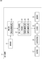
- FIG. 1 is a diagram illustrating a configuration example of an embodiment of a display device to which the present technology is applied.
- the display device 11 is a display device that stereoscopically displays a subject using parallax images from a plurality of viewpoints.
- the display device 11 includes an imaging unit 21, a detection unit 22, an assignment control unit 23, a recording unit 24, a generation unit 25, a display control unit 26, and a display unit 27.
- the imaging unit 21 captures and detects an image of a user around the display device 11, for example, an image of a user observing an image displayed on the display unit 27 (hereinafter referred to as a peripheral image) from almost the front of the display unit 27. Supplied to the unit 22.
- the detection unit 22 detects the user's eyes from the peripheral image supplied from the imaging unit 21 and supplies the detection result to the assignment control unit 23.
- the detection unit 22 includes a viewpoint position calculation unit 31, and the viewpoint position calculation unit 31 calculates a user's viewpoint position with respect to the display unit 27 based on the peripheral image and supplies the calculated position to the assignment control unit 23.
- the allocation control unit 23 allocates a plurality of parallax images to each region on the display surface of the display unit 27 based on the detection result from the detection unit 22 and the viewpoint position of the user.
- the allocation control unit 23 includes a determination unit 32, a visual position calculation unit 33, and a boundary position calculation unit 34.
- the determination unit 32 determines whether or not stereoscopic display (3D display) of a subject using a plurality of parallax images is possible, and the allocation control unit 23 determines whether or not the subject is stereoscopically displayed. Image generation in the generation unit 25 is controlled.
- the visual recognition position calculation unit 33 calculates the position in the pixel on the display surface of the display unit 27 visually recognized by the user as the visual recognition position based on the viewpoint position from the detection unit 22.
- the boundary position calculation unit 34 assigns a plurality of parallax images to each region on the display surface of the display unit 27 based on the visual recognition position.
- the recording unit 24 records a plurality of parallax images constituting a stereoscopic image, and supplies the parallax images to the generation unit 25 as necessary.
- the generation unit 25 Based on the parallax image from the recording unit 24, the generation unit 25 generates a synthesized image obtained by spatially dividing these parallax images and supplies the synthesized image to the display control unit 26 under the control of the allocation control unit 23.
- the generation unit 25 supplies any of the parallax images from the recording unit 24 to the display control unit 26 as it is under the control of the allocation control unit 23.
- the display control unit 26 supplies the composite image from the generation unit 25 to the display unit 27 to display the stereoscopic image of the subject on the parallax image, or supplies the parallax image from the generation unit 25 to the display unit 27.
- the display unit 27 includes a liquid crystal display panel that can display a stereoscopic image by the naked eye method, and displays a composite image or a parallax image supplied from the display control unit 26.
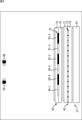
- [Configuration example of display unit] 1 is configured as shown in FIG. 2, for example.
- the display unit 27 includes a backlight 61, a light modulation panel 62, and a barrier element 63.
- the backlight 61 includes, for example, an LED (Light Emitting Diode) light source, a light guide plate, and the like, emits light for displaying an image, and enters the light modulation panel 62.
- LED Light Emitting Diode
- the light modulation panel 62 is made of, for example, a liquid crystal layer or color filters of R, G, and B colors, and transmits light incident from the backlight 61 to display an image. At this time, the light modulation panel 62 performs gradation display of each pixel of the image by changing the light transmittance for each pixel provided in the light modulation panel 62.
- the light modulation panel 62 includes a transparent substrate 71, a transparent substrate 72, and a liquid crystal layer 73.
- the liquid crystal layer 73 is a flat transparent substrate 71 and a transparent substrate that are disposed so as to face each other. 72 is formed.
- the liquid crystal layer 73 is provided with a transmissive portion as a pixel for displaying an image.
- the barrier element 63 includes a polarizing plate, a switch liquid crystal layer, and the like.
- the barrier element 63 optically separates the parallax images by blocking a part of the light incident from the light modulation panel 62 and transmitting the remaining part.
- the barrier element 63 includes a transparent substrate 74, a transparent substrate 75, and a switch liquid crystal layer 76, and the switch liquid crystal layer 76 is disposed between the flat transparent substrate 74 and the transparent substrate 75 arranged so as to face each other. Is formed.
- Electrodes are formed on the transparent substrate 74 and the transparent substrate 75, and when a voltage is applied to some or all of these electrodes, the orientation direction of the liquid crystal molecules in the switch liquid crystal layer 76 changes, thereby A parallax barrier is formed in the switch liquid crystal layer 76.
- the openings 81-1 to 81-3 that transmit the light incident from the light modulation panel 62 and the shielding portions 82-1 to 82-3 that shield the light incident from the light modulation panel 62 are used.
- -3 is formed in the switch liquid crystal layer 76.
- openings 81-1 to 81-3 are also simply referred to as the openings 81, and it is not necessary to particularly distinguish the shielding parts 82-1 to 82-3. Also simply referred to as a shielding portion 82.
- a parallax barrier is formed on the barrier element 63, but a parallax image that is a 2D image is displayed on the light modulation panel 62. In that case, no parallax barrier is formed in the barrier element 63.
- the user observes an image displayed on the light modulation panel 62 from the barrier element 63 side.
- the barrier element 63 when a composite image is displayed, light emitted from the backlight 61 and transmitted through the light modulation panel 62 and the barrier element 63 is incident on the user's right eye ER or left eye EL.
- different lights separated by the barrier element 63 are incident on the user's right eye ER and left eye EL, different parallax images having parallax are observed between the right eye ER and the left eye EL.
- the barrier element 63 has been described as an example of a separation unit that optically separates parallax images.
- the separation unit is not limited to a parallax barrier, and may be a lenticular lens or the like.
- the parallax barrier as the separation unit is not limited to a variable barrier, and may be a fixed barrier in which an opening is provided in a shielding plate or the like.
- the barrier element 63 may be disposed between the light modulation panel 62 and the backlight 61.
- the intermediate position between the user's right eye ER and left eye EL is the user's viewpoint position
- the user's viewpoint position is a distance Z0 from the surface of the barrier element 63 (hereinafter referred to as an appropriate viewing distance Z0).
- the distance between the right eye ER and the left eye EL is 65 mm.
- a typical adult interocular distance is about 65 mm.
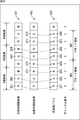
- one square in the light modulation panel 62 represents one pixel, and in the figure of those pixels, the channel number to which each pixel belongs is shown below.
- the horizontal direction and the vertical direction are the x direction and the y direction, respectively, and the direction perpendicular to the x direction and the y direction is the z direction.
- the x direction is the direction in which the user's right eye ER and left eye EL are arranged, that is, the parallax direction of the parallax image displayed on the light modulation panel 62
- the y direction is the direction perpendicular to the display surface of the light modulation panel 62. It is.
- the pixel of channel CH0, the pixel of channel CH1, the pixel of channel CH2, and the pixel of channel CH3 are arranged in order from the right side to the left side.
- pixels of the same channel are arranged in the z direction, for example.
- Such block areas are continuously arranged in the x direction on the display surface of the light modulation panel 62.
- an area composed of pixels of the same channel in one block area is also referred to as a channel area.
- the barrier element 63 is provided with one opening 81 constituting a parallax barrier for one block region. Accordingly, when the parallax images of the viewpoints P0 to P3 are displayed on the pixels of the channels CH0 to CH3, the parallax images of the viewpoints are optically separated by the barrier element 63.
- the light emitted from each pixel of the channel CH3 and passed through the opening 81 reaches the region CR0 and is emitted from each pixel of the channel CH2.
- the light that has passed through the opening 81 reaches the region CR1.
- light emitted from each pixel of the channel CH1 and passed through the opening 81 reaches the region CR2, and light emitted from each pixel of the channel CH0 and passed through the opening 81 reaches the region CR3.
- the numbers 0 to 3 arranged in the x direction on the upper side indicate the channel numbers of the pixels from which the light reaching the area where the number is written is emitted.
- the number “3” on the upper side in the drawing of the region CR0 indicates that the light from the pixel of the channel CH3 reaches the region CR0.
- the parallax of the viewpoint P1 is respectively displayed on the user's right eye ER and left eye EL. The image and the parallax image of the viewpoint P2 are observed. As a result, the subject on the parallax image is perceived three-dimensionally by the user.
- the parallax image at the viewpoint P0 and the parallax image at the viewpoint P1 are respectively displayed on the user's right eye ER and left eye EL. Will be observed.
- pixels adjacent to each other on the light modulation panel 62 are observed through the opening 81 in the left and right eyes of the user.
- the appropriate viewing distance Z0 is 900 mm
- a distance D1 from the opening 81 to the light modulation panel 62 and a distance D2 between the openings 81 are determined as shown in FIG.
- the horizontal direction and the vertical direction indicate the x direction and the y direction.
- each square on the lower side represents a pixel on the light modulation panel 62.
- one pixel G11 is visually recognized through the opening 81 from the position PE11 of the user's eye as shown on the left side in the figure. Assuming that the distance between the pixels is D3, the center of the pixel G11 is at a position away from the straight line A11 by (D3) / 2.
- the position of the light modulation panel 62 seen through the screen should be separated by 4 pixels.
- the light from one point on the light modulation panel 62 of the display unit 27 includes the light that reaches the left end of the region CR2 through the position of the user's right eye ER and the region that passes through the position of the left eye EL. And light reaching the right end of CR1.
- the distance in the x direction between the arrival points of these lights is twice the distance E between the eyes. That is, there is a shift by two viewpoints.
- the channel of the block region is transmitted from the user's left eye EL through the same opening 81.
- the CH3 pixel is visible.
- each area (block area) of the display unit 27 The region on the xz plane where the light passing through the eye position reaches is different.
- the channel number of the pixel from which the light that reaches the region is emitted. Has been.
- the right eye ER of the user is connected to the right eye ER via the opening 81.
- the pixel of channel CH2 is visually recognized. That is, the light emitted from the pixel of the channel CH2 enters the user's right eye ER through the opening 81.
- the pixel of the channel CH1 is visually recognized by the user's right eye ER through the opening 81. Furthermore, in the area of the light modulation panel 62, which is the third block from the left end and the right end of the block modulation area 62, the right eye ER of the user is connected to the pixel of the channel CH0 through the opening 81, respectively. And the pixel of channel CH3 is visually recognized.
- the squares indicated by the arrows Q11 represent the areas on the light modulation panel 62, and the numbers in these areas indicate the channel numbers of the pixels that are visually recognized by the user's right eye ER.
- the upper curve indicates the luminance distribution of light emitted from the pixels of each area and reaching the user's right eye ER. For example, at the left end of the area where the channel number “3” is written on the light modulation panel 62, the light from the pixel of the channel CH3 and the light from the pixel of the channel CH0 are incident on the right eye ER of the user with the same luminance. To do.
- the pixel of the channel CH0 is connected to the left eye EL of the user via the opening 81. Visible.
- the pixel of the channel CH3 is visually recognized by the user's left eye EL through the opening 81. Furthermore, in the area of the light modulation panel 62, which is the third block from the left end and the right end of the block modulation area 62, the left eye EL of the user is connected to the pixel of the channel CH2 via the opening 81, respectively. And the pixel of channel CH1 is visually recognized.
- rectangles indicated by the arrows Q12 represent the respective areas on the light modulation panel 62, and the numbers in these areas indicate the channel numbers of the pixels that are visually recognized by the user's left eye EL. Further, in the quadrangular diagram representing each region, the upper curve indicates the luminance distribution of light emitted from the pixels of each region and reaching the user's left eye EL.
- the right-eye and left-eye parallax images are appropriately displayed on the pixels of each channel, and the user has the appropriate viewing distance Z0. If a parallax image is observed from about half the distance, the occurrence of crosstalk can be suppressed.
- the user's right eye ER observes the pixel of channel CH1
- the user's left eye EL observes the pixel of channel CH2. From this state, for example, it is assumed that the user has moved slightly to the right in FIG. Then, since the pixel of the channel CH1 and the pixel of the channel CH2 are adjacent to each other, not only the pixel of the channel CH1 that has been seen so far but also the channel CH2 that has been seen by the left eye EL to the user's right eye ER. Pixels are also visible and crosstalk occurs. That is, the subject on the left and right parallax images looks double.
- the right-eye parallax image is displayed on the channel CH1 of the block area slightly on the left side from the center in the figure of the light modulation panel 62, and the channel CH3 of the same block area is displayed. It is assumed that a parallax image for the left eye is displayed on the screen.
- the user can feel the switching of the display of the left and right parallax images in each region. Thus, a more natural image can be presented.
- a stereoscopic image display method As described above, according to the viewpoint position of the user, appropriately display the parallax image for the right eye or the left eye on the pixel of each channel, and if the user observes from a distance about half of the normal suitable viewing distance, It is possible to suppress the occurrence of crosstalk and present a higher quality image.
- a semi-viewing distance display method such a stereoscopic image display method is referred to as a semi-viewing distance display method.
- the channel CH0 pixel, the channel CH3 pixel, the channel CH2 pixel, and the channel CH1 pixel are visually recognized by the user's left eye.
- region B14 are areas which consist of a some block area
- the display device 11 specifies the position of the block region where the luminance of the light from the pixel viewed by the user is the highest among the block regions in the regions B11 to B14, These positions are defined as a boundary position LB11 to a boundary position LB14.
- the boundary position LB11 is the position of the block area where the luminance of light from the visible pixel is highest among the block areas in the area B11.
- each of the boundary positions LB12 to LB14 is the position of each of the block areas where the luminance of light from the visible pixel is highest among the block areas in each of the areas B12 to B14.
- the display device 11 assigns left and right parallax images to each channel for each region divided by the boundary position LB11 to the boundary position LB14 on the light modulation panel 62. Do.
- a right-eye parallax image is assigned to the pixels of the channel CH2 and the channel CH3, and the pixels of the channel CH0 and the channel CH1 are left.
- An eye parallax image is assigned.
- a right-eye parallax image is assigned to the channel CH1 and channel CH2 pixels, and a left-eye parallax image is assigned to the channel CH0 and channel CH3 pixels.
- a parallax image is assigned.
- a right-eye parallax image is assigned to the channel CH0 and channel CH1 pixels, and a left-eye parallax is assigned to the channel CH2 and channel CH3 pixels.
- An image is assigned.
- a parallax image for the right eye is allocated to the pixels of the channel CH0 and the channel CH3, and a parallax for the left eye is allocated to the pixels of the channel CH1 and the channel CH2.
- An image is assigned.
- a right-eye parallax image is assigned to the channel CH2 and channel CH3 pixels, and a left-eye parallax image is assigned to the channel CH0 and channel CH1 pixels.
- a parallax image is assigned.
- a composite image is generated according to the assignment of the parallax image to each channel in such a block region, and the generated composite image is displayed on the light modulation panel 62.
- the channel of the pixel visually recognized by the user in each block area changes, so the positions of the boundary positions LB11 to LB14 also move following the change of the viewpoint position. To do. Then, according to the movement of the boundary position LB11 to the boundary position LB14, the assignment of parallax images to the pixels of each channel in the block region is changed.
- an area composed of several block areas arranged in succession, and an area composed of block areas in which the same parallax image is assigned to pixels of the same channel is also referred to as a continuous block area.
- a region composed of each block region between the boundary position LB11 and the boundary position LB12 and a region composed of each block region between the boundary position LB12 and the boundary position LB13 are one continuous.
- the block area That is, in FIG. 7, each of the boundary positions LB11 to LB14 becomes a boundary of the continuous block region.
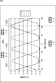
- the boundary position of the continuous block area is the position of the block area where the luminance of the light from the pixel visually recognized by the user is the highest. For example, as shown in FIG. The pixel of the channel different from the high pixel has the lowest luminance.
- the horizontal axis indicates the viewpoint position of the user in the x direction
- the vertical axis indicates the light transmittance from the pixels of each channel in the predetermined block region at those positions, that is, the pixels of each channel. The brightness of the light from is shown.
- FIG. 8 shows the luminance of light from the pixels of each channel incident on the user's eyes when the user's viewpoint position is at each position when focusing on a specific block region.
- each of the two-dot chain line, the one-dot chain line, the dotted line, and the solid line indicates the luminance of light from the pixels of the channels CH0 to CH3.
- the luminance of light from a predetermined pixel observed by the user is maximized. Therefore, for example, when the user's right eye is at the position LB22, since the center of the pixel of the channel CH1 of the block area of interest is observed by the user's right eye, this block area is defined as the boundary position of the continuous block area. Become.
- the parallax image for the right eye is displayed on the pixels of the channel CH0 and the channel CH1 in the block area of interest.
- a parallax image for the right eye is displayed on the pixels of the channel CH1 and the channel CH2 in the block area of interest. Will come to be.
- the display of the parallax image for the right eye is switched from the channel CH0 and the channel CH1 to the channel CH1 and the channel CH2 in the block area of interest. That is, the light from the pixels of different channels is perceived by the right eye of the user due to the movement of the viewpoint position of the user.
- the luminance of the pixels of the other channels CH0 and CH2 is relatively lowest with respect to the luminance of the pixel of the channel CH1. Therefore, in the vicinity of the position LB22, what is observed by the user's right eye is almost light from the pixel of the channel CH1, and the parallax image is assigned from the channel CH0 to the channel CH2 with the luminance of the other pixels being the lowest. Will be switched to. As a result, it is possible to present a high-quality image without causing the user to feel uncomfortable.
- the boundary position of the continuous block area is the position of the block area where the luminance of light from the pixel visually recognized by the user is highest.
- the block region having the highest luminance is a block region where the approximate center of the pixel is visually recognized by the user.
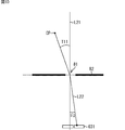
- a predetermined light beam H11 passes through the air, enters a glass material having a thickness D21, and reaches the surface of the light modulation panel 62.
- a straight line passing through the incident position of the light beam H11 on the glass material and perpendicular to the surface of the glass material is defined as a straight line A21.
- the horizontal direction in the figure that is, the direction parallel to the display surface of the light modulation panel 62 is the x direction
- the vertical direction in the figure that is, the display surface of the light modulation panel 62.
- a predetermined position on the xy coordinate system is a position CP of the user's eyes, where the direction perpendicular to the y direction is the y direction.
- the opening 81 in the center of the barrier element 63 is defined as the 0th opening 81
- the nth opening 81 in the left direction from the opening 81 in the figure is defined as the nth opening 81, and the 0th.
- the n-th opening 81 in the right direction from the first opening 81 is defined as the ⁇ n-th opening 81.
- the incident angle T11 of the light beam from the position CP to the nth opening 81 is obtained. That is, the incident angle T11 is an angle formed by the straight line L21 parallel to the y direction and the light beam from the position CP.
- the position in the pixel visually recognized by the user is a value between ⁇ 0.5 and 0.5, with the center position of the pixel being 0.
- the right end position in the pixel diagram is ⁇ 0.5
- the left end position in the pixel diagram is 0.5.
- the channel m of the pixel (hereinafter also referred to as a visible pixel) visually recognized by the user for each block region (opening 81), and the visual position on the visible pixel
- the result shown on the right side of FIG. 11 is obtained.
- the horizontal axis indicates the number n of the opening 81
- the vertical axis indicates the channel number or the viewing position of the viewing pixel.
- the broken line C11 indicates the channel number of the visible pixel in each block area visible from the user's right eye
- the broken line C12 indicates the visual recognition position in the visible pixel of each block area visible from the user's right eye.
- the direction from the 0th opening 81 toward the nth (where 1 ⁇ n) opening 81 is the + x direction
- the direction opposite to the + x direction is the ⁇ x direction.
- the pixel of the channel CH1 is visually recognized through the openings 81 to the right eye of the user who observes some openings 81 adjacent to the 0th opening 81 on the + x direction side.
- the substantially center of the pixels of the channel CH1 is observed by the user's right eye through the opening 81. You can see that.
- the channel CH2 pixel is observed in the right eye of the user, and the left side of the figure is the left side in the figure.
- the pixel of the channel CH1 is observed in the right eye of the user.
- the pixel of the channel CH0 is observed in the user's right eye, and in the region adjacent to the left side of the region, the user's right The pixel of channel CH3 is observed in the eye.
- boundary positions LB51 to LB54 are determined.
- a parallax image for the right eye is assigned to pixels of two channels that are viewed pixels in the continuous block area.
- a parallax image for the right eye is assigned to the pixels of the channel CH2 and the channel CH3. Also, between the boundary position LB51 and the boundary position LB52, parallax images for the right eye are assigned to the pixels of the channel CH0 and the channel CH3, and between the boundary position LB52 and the boundary position LB53, the channel CH0 and the channel CH1. A right-eye parallax image is assigned to the pixel.
- right-eye parallax images are assigned to the pixels of the channel CH1 and the channel CH2, and between the boundary position LB54 and the end of the light modulation panel 62 on the + x direction side. , Right-eye parallax images are assigned to the pixels of channel CH2 and channel CH3.
- the broken line C13 indicates the channel number of the visible pixel in each block area visible from the user's left eye
- the broken line C14 indicates the block area visible from the user's left eye.
- the visual recognition position in the visual recognition pixel is shown.
- the pixel of the channel CH3 is visually recognized through the openings 81 to the left eye of the user who observes some openings 81 adjacent to the 0th opening 81 on the + x direction side. I understand.
- a parallax image for the left eye is assigned to pixels of two channels that are viewed pixels in the continuous block area.
- a left-eye parallax image is assigned to the pixels of the channel CH0 and the channel CH1. Also, between the boundary position LB61 and the boundary position LB62, parallax images for the left eye are assigned to the pixels of the channel CH1 and the channel CH2, and between the boundary position LB62 and the boundary position LB63, the channel CH2 and the channel CH3. A left-eye parallax image is assigned to the pixel.
- the parallax images for the left eye are assigned to the pixels of the channel CH0 and the channel CH3, and between the boundary position LB64 and the end of the light modulation panel 62 on the + x direction side.
- the parallax images for the left eye are assigned to the pixels of channel CH0 and channel CH1.
- the boundary position of the continuous block region is determined.
- a channel to which the left and right parallax images are assigned is determined for each block area belonging to each continuous block area.
- the boundary position of the continuous block area is ideally the same as the boundary position when viewed from the right eye and the boundary position when viewed from the left eye. Since the positions of the eyes and the left eye are different from each other, a shift occurs in the boundary position between them.
- the horizontal axis indicates the number n of the opening 81
- the vertical axis indicates the channel number or the viewing position of the viewing pixel.
- a broken line C ⁇ b> 21 indicates a channel number of a visible pixel in each block area visible from the user's right eye
- a broken line C ⁇ b> 22 indicates a visible position in the visible pixel of each block area visible from the user's right eye.
- straight lines LB71 to LB74 indicate the boundary positions of the continuous block regions determined from the polygonal line C22.
- the broken line C23 indicates the channel number of the visible pixel in each block area visible from the user's left eye
- the broken line C24 indicates the visual recognition position in the visible pixel of each block area visible from the user's left eye.
- straight lines LB81 to LB84 indicate the boundary positions of the continuous block areas determined from the polygonal line C24.
- straight lines LB71 to LB74 are also referred to as boundary positions LB71 to LB74
- straight lines LB81 to LB84 are also referred to as boundary positions LB81 to LB84.
- each of the boundary positions LB81 to LB84 based on the left eye corresponds to the boundary positions LB71 to LB74 based on the right eye.
- the boundary position located farther from the center of the modulation panel 62 is larger.
- the right-eye parallax image is assigned to the pixels of the channel CH0 and the channel CH3 in the block region between the boundary position LB71 and the boundary position LB72 with the right eye as a reference.
- a parallax image for the left eye is assigned to the pixels of the channel CH0 and the channel CH1 in the block region between the end of the light modulation panel 62 on the ⁇ x direction side and the boundary position LB81 with the left eye as a reference.
- both the right-eye parallax image and the left-eye parallax image are assigned to the pixel of the channel CH0.
- the boundary positions LB71 to LB74 and the intermediate positions (average positions) between the boundary positions LB81 to LB84 are determined as boundary positions LB91 to Boundary positions which are final boundary positions. LB94.
- the area divided by the boundary position LB91 to the boundary position LB94 is set as a continuous block area, and a parallax image is allocated in each block area.
- the channel numbers of the pixels to which the parallax images for the right eye and the left eye are assigned in each region are shown on the lower side.
- a right-eye parallax image is assigned to the channel CH0 and channel CH3 pixels in the block region, and a left-eye parallax image is assigned to the channel CH1 and channel CH2 pixels. Is assigned.
- a right-eye parallax image is assigned to the pixels of the channel CH0 and the channel CH1 in the block region, and a left-eye parallax image is assigned to the pixels of the channel CH2 and the channel CH3. Assigned.
- the boundary position between the boundary position based on the right eye and the boundary position based on the left eye is the boundary position of the final continuous block region, the right eye or the left eye is used as the reference in the vicinity of the boundary position.
- pixels in the same channel are observed as visual pixels in the user's right eye and left eye in some block areas.
- the horizontal axis indicates the number n of the opening 81
- the vertical axis indicates the channel number or the viewing position of the viewing pixel.
- the broken line C31 indicates the channel number of the visible pixel in each block area visible from the user's right eye
- the broken line C32 indicates the visual recognition position in the visible pixel of each block area visible from the user's right eye.
- a broken line C33 indicates the channel number of the visible pixel in each block area visible from the user's left eye
- a broken line C34 indicates the visual recognition position in the visible pixel of each block area visible from the user's left eye.
- the polygonal line C31 and the polygonal line C33 partially overlap, and in these parts, pixels in the same channel are observed as visual pixels in the block area by the user's right eye and left eye. Therefore, even if an intermediate position between the boundary position obtained with reference to the right eye and the boundary position obtained with reference to the left eye is set as the boundary position of the final continuous block region, the right eye is assigned to the same channel in a predetermined block region. Both parallax images for left and right eyes must be assigned. That is, the user cannot observe the subject stereoscopically, and stereoscopic display using the parallax image for the right eye and the parallax image for the left eye becomes impossible.
- the parallax is obtained when the user observes the display unit 27 from the current viewpoint position. It is possible to specify whether an image can be stereoscopically viewed.
- an operation for obtaining a visible pixel for each block area is performed for each viewpoint position, for example, as shown in FIG. 14, an area capable of stereoscopic display (stereoscopic view) and an impossible area are obtained on the xy plane. be able to.
- the horizontal direction and the vertical direction indicate the x direction and the y direction.
- a hatched area WR ⁇ b> 11 among the areas around the display unit 27 indicates an area in which a parallax image can be stereoscopically displayed. Therefore, when the stereoscopic display of the parallax image is performed by the semi-view distance display method, the display device 11 sets the region WR12 in the region WR11 as a region where the stereoscopic display of the parallax image is possible. The display device 11 stereoscopically displays the subject based on the left and right parallax images when the user's viewpoint position is within the region WR12, and when the user's viewpoint position is outside the region WR12, A parallax image is displayed.
- the display device 11 performs display processing when a stereoscopic image including a parallax image for the right eye and a parallax image for the left eye is designated, and display of these parallax images by the semi-viewing distance display method is instructed, A parallax image is stereoscopically displayed.
- display processing by the display device 11 will be described with reference to the flowchart of FIG.
- step S ⁇ b> 11 the imaging unit 21 captures an image of a region around the display unit 27 as a peripheral image and supplies the image to the detection unit 22.
- step S ⁇ b> 12 the detection unit 22 detects the user's eyes based on the peripheral image supplied from the imaging unit 21. For example, the detection unit 22 detects the user's face from the peripheral image, and further detects the user's eyes from the detected face area.
- step S13 the detection unit 22 determines whether or not the user's eyes are detected from the surrounding images.
- step S14 the viewpoint position calculation unit 31 calculates the user's viewpoint position from the detected user's eye position, and sends it to the assignment control unit 23. Supply. For example, the viewpoint position calculation unit 31 obtains an intermediate position between the left and right eyes of the user on the xy plane as the viewpoint position.
- step S15 the determination unit 32 of the allocation control unit 23 determines whether or not stereoscopic display of a parallax image is possible based on the viewpoint position of the user supplied from the viewpoint position calculation unit 31.
- the determination unit 32 records area information for specifying the stereoscopically displayable area WR12 shown in FIG. 14 in advance, and based on the recorded area information, the user's viewpoint position is within the area WR12. By specifying whether or not it is a position, it is determined whether or not stereoscopic display is possible. Therefore, for example, when the viewpoint position of the user is a position in the region WR12, it is determined that stereoscopic display is possible.
- step S16 the viewing position calculation unit 33 visually recognizes each opening 81 based on the viewpoint position of the user supplied from the viewpoint position calculation unit 31. Pixels and viewing positions are calculated.
- the visual recognition position calculation unit 33 performs the calculation described with reference to FIG. 10 on the right eye position and the left eye position of the user determined from the viewpoint position, and opens the opening for each opening 81 (block region).
- the visual recognition pixel observed through the part 81 and the visual recognition position in the visual recognition pixel are calculated.
- the calculation result shown in FIG. 11 is obtained. That is, for each block region, a channel number of a pixel (viewing pixel) observed from the user's right eye or left eye and a position (viewing position) observed by the user on the pixel are obtained.
- step S17 the boundary position calculation unit 34 calculates the boundary position of the continuous block area based on the calculation result of the visual recognition position for each block area.
- the boundary position calculation unit 34 determines the position where the visual recognition position is “0” based on the calculation result of the visual recognition position of each block area obtained with respect to the right eye position as the boundary position based on the right eye. And That is, the position of the block region where the center of the pixel is observed by the right eye through the opening 81 is set as the boundary position with the right eye as a reference. Similarly, the boundary position calculation unit 34 determines the position where the visual recognition position is “0” as the boundary position with reference to the left eye based on the calculation result of the visual recognition position of each block region obtained for the left eye position. To do.
- the boundary position calculation unit 34 determines the intermediate position between the boundary position with reference to the right eye and the boundary position with reference to the left eye corresponding to these boundary positions as the boundary of the final continuous block region.
- Position the boundary position based on the left eye, which corresponds to the boundary position based on the right eye, is the boundary position based on the left eye that is closest to the boundary position based on the right eye. is there.
- step S18 the boundary position calculation unit 34 assigns right-eye or left-eye parallax images to the pixels in each block area based on the calculation result of the boundary position of the continuous block area.
- the pixels (channel areas) of the channel CH0 and the channel CH3 A parallax image for the right eye is assigned. Also, in the block region between the boundary position LB91 and the boundary position LB92, a parallax image for the left eye is assigned to the pixels of the channel CH1 and the channel CH2.
- an area composed of four pixels on the light modulation panel 62 is a block area BR1 and a block area BR2.
- the horizontal direction indicates the x direction.
- the rectangles indicated by arrows Q41 to Q43 represent the parallax image for the right eye, the parallax image for the left eye, and the light modulation panel 62.
- one rectangle in the rectangle represents one pixel, and the characters “R”, “G”, and “B” in each pixel represent the color of the pixel.
- a region including the pixels G51 to G54 on the light modulation panel 62 is a block region BR1
- a region including the pixels G55 to G58 is a block region BR2.
- the pixel G51 is a pixel that is provided with an R (red) color filter and transmits only R light
- the pixel G52 is a G light that is provided with a G (green) color filter. It is a pixel that transmits only.
- each pixel on the light modulation panel 62 the channel numbers of these pixels are written on the lower side.
- the pixel G51 is a pixel of the channel CH0
- the pixel G52 is a pixel of the channel CH1.
- pixels on an image have values of R, G, and B colors
- adjacent R, G, and B areas are defined as one pixel
- R, G, and B color areas are defined as one pixel. It is often treated as a subpixel (subpixel).
- a region composed of three consecutive pixels of R, G, and B at the left end is generally one pixel (hereinafter also referred to as RGB pixel as appropriate).
- the pixels G61 and G62 of each color are treated as sub-pixels. However, here, these pixels G61 and G62 are referred to as one pixel.
- three color regions including the pixels G51 to G53 may be treated as one pixel, but here, each of the pixels G51 to G53 is treated as one pixel. To do.
- the boundary position calculation unit 34 assigns a right-eye parallax image to the pixels of the channel CH0 and the channel CH1, and a parallax image for the left eye to the pixels of the channel CH2 and the channel CH3. Is assigned.
- the boundary position calculation unit 34 assigns the pixel G61 and the pixel G62 of the parallax image for the right eye to the pixel G51 and the pixel G52 on the light modulation panel 62 at the same position as those pixels. Further, the boundary position calculation unit 34 assigns the pixel G71 and the pixel G72 of the parallax image for the left eye to the pixel G53 and the pixel G54 on the light modulation panel 62 at the same position as those pixels.
- the boundary position calculation unit 34 assigns the pixel G63 and the pixel G64 of the parallax image for the right eye to the pixel G55 and the pixel G56, the pixel G73 and the pixel G74 of the parallax image for the left eye, and the pixel G57 and the pixel G57. Assign to G58.
- a right-eye or left-eye parallax image is assigned to a predetermined channel of a block region, more specifically, a pixel of the channel is used for the right eye or the same position as the pixel. Pixels of the parallax image for the left eye are assigned.
- the boundary position calculation unit 34 supplies the assignment result to the generation unit 25, and the composite image Instruct the generation of.
- step S ⁇ b> 19 the generation unit 25 generates a composite image based on the allocation result supplied from the boundary position calculation unit 34 and the right-eye and left-eye parallax images read from the recording unit 24, and displays them. It supplies to the control part 26. For example, when the assignment illustrated in FIG. 16 is performed, the generation unit 25 displays the pixel G61 and the pixel G62 of the parallax image for the right eye on the pixel G51 and the pixel G52, and the pixel of the parallax image for the left eye. A composite image is generated so that G71 and pixel G72 are displayed on pixel G53 and pixel G54.
- the parallax image may be acquired from an external device or the parallax image may be received.
- step S20 the display control unit 26 supplies the composite image supplied from the generation unit 25 to the display unit 27 for display.
- the display unit 27 emits light from the backlight 61 based on the supplied composite image, and applies a voltage to the light modulation panel 62 to control the transmittance of light from the backlight 61 for each pixel. Further, the display unit 27 applies a voltage to the barrier element 63 to form a parallax barrier composed of the opening 81 and the shielding unit 82.
- the light transmitted through each pixel of the light modulation panel 62 from the backlight 61 is optically separated by the parallax barrier, and a part of the separated light is incident on the right eye or the left eye of the user,
- the user observes the subject on the parallax image stereoscopically. That is, the parallax image area for the right eye on the synthesized image is observed by the user's right eye, and the parallax image area for the left eye on the synthesized image is observed by the user's left eye.
- the display device 11 outputs the accompanying sound from a speaker (not shown) in accordance with the display of the composite image.
- step S21 the display device 11 determines whether to turn off the power of the display device 11. For example, when an instruction to turn off the power is given by a user operation, it is determined that the power is turned off.
- step S21 If it is determined in step S21 that the power is not turned off, the process returns to step S11 and the above-described process is repeated. That is, according to the movement of the user's viewpoint position, the assignment of the parallax image to the pixel of each channel in the block region is changed, and the composite image generated according to the new assignment is displayed.
- step S21 when it is determined in step S21 that the power is turned off, the display device 11 stops the processing of each unit and turns off the power, and the display process ends.
- step S15 If it is determined in step S15 that stereoscopic display is not possible, the allocation control unit 23 instructs the generation unit 25 to display a two-dimensional parallax image, and the process proceeds to step S22.
- step S22 the generation unit 25 displays a two-dimensional parallax image in response to an instruction from the allocation control unit 23. That is, the generation unit 25 reads out the right-eye or left-eye parallax image from the recording unit 24 and supplies the read-out parallax image to the display control unit 26 as it is.
- the display control unit 26 supplies the parallax image supplied from the generation unit 25 to the display unit 27 to display the parallax image.
- the barrier element 63 does not form a parallax barrier, and the display unit 27 displays the parallax image as it is.
- the parallax image is displayed two-dimensionally (2D display) by causing the display unit 27 to display the parallax image as it is.
- step S22 When the parallax image is displayed in step S22, the process thereafter proceeds to step S21, and the above-described process is performed.
- step S13 If it is determined in step S13 that the user's eyes have not been detected, the detection unit 22 supplies a detection result indicating that no eyes have been detected to the assignment control unit 23, and the process proceeds to step S23.
- step S23 the allocation control unit 23 determines whether or not a predetermined time has elapsed since the user's eyes are not detected.
- step S23 If it is determined in step S23 that the predetermined time has not elapsed, the process proceeds to step S22, and the above-described process is performed. That is, the parallax image is two-dimensionally displayed on the display unit 27.
- step S24 the allocation control unit 23 controls the generation unit 25 so that no image is displayed.
- the generation unit 25 stops the supply of the image to the display control unit 26 according to the control of the allocation control unit 23. As a result, no image is displayed on the display unit 27. That is, the image is erased.
- the power consumption can be suppressed by erasing the image.
- step S24 If it is determined that the image is erased in step S24, then the process proceeds to step S21, the above-described process is performed, and the display process ends.
- the display device 11 calculates the viewing pixel and the viewing position for each block area based on the viewpoint position of the user, and based on the calculation result, the display device 11 applies the right eye to the pixel of each channel in the block area.
- a composite image is generated by assigning parallax images for the left eye or the left eye.
- the same parallax image of the right-eye or left-eye parallax images is assigned to at least two pixels arranged adjacent to each other in the x direction of the block region, so that crosstalk can be more easily performed.
- production can be suppressed and a higher quality image can be shown now.
- the user can feel more natural without switching the display of the parallax image in each channel. Can present high-quality images.
- the determination unit 32 records in advance area information for specifying an area that can be stereoscopically displayed.
- area information is not recorded in advance and is visually recognized. Whether or not stereoscopic display is possible may be determined from the pixel calculation result.
- the determination unit 32 uses the calculation result of the visual pixel in each block area calculated by the visual position calculation unit 33. That is, the determination unit 32 determines that stereoscopic display is not possible when there is a block region in which a visual pixel based on the right eye and a visual pixel based on the left eye are pixels of the same channel.
- ⁇ Modification 1> In the above description, it has been described that the display device 11 performs stereoscopic display by the semi-viewing distance display method alone. However, a stereoscopic display by the semi-viewing distance display method is performed by a display system including several devices. It may be.
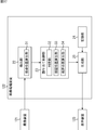
- the display system is configured as shown in FIG.
- the display system of FIG. 17 includes an imaging device 121, an image processing device 122, and a display device 123.
- the same reference numerals are given to the portions corresponding to those in FIG. 1, and description thereof will be omitted as appropriate.
- the imaging device 121 captures an image around the display device 123 as a peripheral image and supplies it to the image processing device 122.
- the image processing device 122 generates a composite image using the peripheral image from the imaging device 121 and supplies the composite image to the display device 123.
- the image processing apparatus 122 includes a detection unit 22, an assignment control unit 23, a recording unit 24, and a generation unit 25.
- the detection unit 22 detects the user's eyes from the peripheral image from the imaging device 121 and supplies the detection result to the allocation control unit 23.
- the allocation control unit 23 is based on the detection result from the detection unit 22.
- the parallax image is assigned to the pixel of each channel in the block area.
- the generation unit 25 generates a composite image from the parallax images of the left and right eyes recorded in the recording unit 24 according to the control of the assignment control unit 23 and supplies the composite image to the display device 123.
- the display device 123 is a display device that has the same functions as the display unit 27 and the display control unit 26 and can display a stereoscopic image. Based on the composite image supplied from the generation unit 25, the display device 123 displays a subject on the parallax image. Is displayed in 3D.
- the display unit 27 is a display device capable of stereoscopically displaying parallax images of four viewpoints.
- the display unit 27 can stereoscopically display parallax images of five or more viewpoints. It may be a display device.
- the display unit 27 can stereoscopically display a parallax image of six viewpoints, as illustrated in FIG. 18, an area including pixels of six different channels is set as a block area, and one opening is provided for the block area. A part 81 is provided.
- FIG. 18 parts corresponding to those in FIG. 3 are denoted by the same reference numerals, and description thereof is omitted as appropriate.
- an area including the pixels G91 to G96 of six different channels is defined as one block area.
- the viewpoint position of the user who can stereoscopically view the parallax image is such a position that the pixels located at a distance of 3 pixels from each other become the viewing pixels based on the user's right eye and left eye.
- the pixel G95 is visually recognized by the user's right eye ER
- the pixel G92 is visually recognized by the user's left eye EL.
- parallax images for right eye or left eye are assigned to pixels of at least three consecutively arranged channels. For example, in FIG. 18, parallax images for the left eye are allocated to the pixels G91 to G93, and parallax images for the right eye are allocated to the pixels G94 to G96.
- the right and left eye viewing pixels are arranged two or more pixels continuously arranged in the parallax direction.
- a parallax image of the same viewpoint can be assigned to the above pixels.
- the series of processes described above can be executed by hardware or software.
- a program constituting the software may execute various functions by installing a computer incorporated in dedicated hardware or various programs. For example, it is installed from a program recording medium in a general-purpose personal computer or the like.
- FIG. 19 is a block diagram showing an example of a hardware configuration of a computer that executes the above-described series of processing by a program.
- a CPU Central Processing Unit
- ROM Read Only Memory
- RAM Random Access Memory
- An input / output interface 205 is further connected to the bus 204.
- the input / output interface 205 includes an input unit 206 including a keyboard, a mouse, and a microphone, an output unit 207 including a display and a speaker, a recording unit 208 including a hard disk and nonvolatile memory, and a communication unit 209 including a network interface.
- a drive 210 for driving a removable medium 211 such as a magnetic disk, an optical disk, a magneto-optical disk, or a semiconductor memory is connected.
- the CPU 201 loads, for example, the program recorded in the recording unit 208 to the RAM 203 via the input / output interface 205 and the bus 204, and executes the program. Is performed.
- Programs executed by the computer (CPU 201) are, for example, a magnetic disk (including a flexible disk), an optical disk (CD-ROM (Compact Disc-Read Only Memory), DVD (Digital Versatile Disc), etc.), a magneto-optical disk, or a semiconductor.
- the program is recorded on a removable medium 211 that is a package medium including a memory or the like, or provided via a wired or wireless transmission medium such as a local area network, the Internet, or digital satellite broadcasting.
- the program can be installed in the recording unit 208 via the input / output interface 205 by attaching the removable medium 211 to the drive 210.
- the program can be received by the communication unit 209 via a wired or wireless transmission medium and installed in the recording unit 208.
- the program can be installed in the ROM 202 or the recording unit 208 in advance.
- the program executed by the computer may be a program that is processed in time series in the order described in this specification, or in parallel or at a necessary timing such as when a call is made. It may be a program for processing.
- the present technology can be configured as follows.
- a display unit provided with a plurality of block regions each including pixels of three or more channels; A separation unit that separates an image displayed on a pixel of each channel in the block region; According to the viewpoint position of the user observing the display unit, a parallax image is displayed in a first area consisting of a plurality of pixels adjacent to each other in the block area, and pixels of two or more different channels, and the parallax Any of a plurality of parallax images is displayed on each channel pixel in the block area so that another parallax image having parallax with the image is displayed in a second area different from the first area in the block area.
- An assignment control unit for assigning A display device comprising: a generation unit configured to combine a plurality of parallax images according to the allocation by the allocation control unit and generate a composite image.
- a generation unit configured to combine a plurality of parallax images according to the allocation by the allocation control unit and generate a composite image.
- the allocation control unit Based on the viewpoint position, for each block area, a viewing position calculation unit that obtains a viewing position on a viewing pixel in the block area observed by the user; The position of the block area where the visual recognition position is substantially the center of the visual recognition pixel is calculated as a boundary position, and the block area between the boundary position and another boundary position closest to the boundary position is calculated. And a boundary position calculation unit that assigns the same parallax image to pixels of the same channel in the block region. [5] The boundary position calculation unit is configured to determine the channel of the visible pixel in the block area at the boundary position and the other boundary position with respect to the block area between the boundary position and the other boundary position.
- the display device wherein the same parallax image is assigned to a pixel of the same channel as the channel of the visual recognition pixel in a certain block region.
- the boundary position calculation unit calculates an intermediate position between the boundary position calculated with reference to the user's right eye and the boundary position calculated with reference to the user's left eye as the final boundary position.
- the display device according to [4] or [5].
- the allocation control unit causes the display unit to display one of the parallax images for the right eye or the left eye when the viewpoint position is outside a predetermined region.
- the display device according to any one of [4].
- 11 display device 21 imaging unit, 22 detection unit, 23 allocation control unit, 25 generation unit, 26 display control unit, 27 display unit, 31 viewpoint position calculation unit, 32 determination unit, 33 visual recognition position calculation unit, 34 boundary position calculation Part, 81-1 to 81-3, 81 opening
Landscapes
- Physics & Mathematics (AREA)
- Engineering & Computer Science (AREA)
- Multimedia (AREA)
- Signal Processing (AREA)
- General Physics & Mathematics (AREA)
- Optics & Photonics (AREA)
- Testing, Inspecting, Measuring Of Stereoscopic Televisions And Televisions (AREA)
Abstract
Description
[表示装置の構成例]
図1は、本技術を適用した表示装置の一実施の形態の構成例を示す図である。 <First Embodiment>
[Configuration example of display device]
FIG. 1 is a diagram illustrating a configuration example of an embodiment of a display device to which the present technology is applied.
また、図1の表示部27は、例えば図2に示すように構成される。 [Configuration example of display unit]
1 is configured as shown in FIG. 2, for example.
ところで、表示装置11に4つの異なる視点の視差画像を合成して得られた合成画像を表示し、ユーザが表示部27から所定の距離だけ離れた位置から表示部27を観察する場合について考える。 [Observation of stereoscopic images from appropriate viewing distance]
By the way, consider a case where a composite image obtained by synthesizing parallax images of four different viewpoints is displayed on the
このように、適視距離Z0だけ離れた位置から表示部27を観察するユーザに、各開口部81を介して同じチャンネルの画素が視認されるようにするには、開口部81間の距離や、開口部81から光変調パネル62までの距離などを適切に定める必要がある。 [Parallax barrier design]
Thus, in order for a user observing the
ところで、例えば図5に示すように、ユーザの視点位置が、表示部27からy方向に上述した適視距離の半分の距離Z0/2だけ離れた位置にあるとする。 [Observation from half the optimum viewing distance]
By the way, as shown in FIG. 5, for example, it is assumed that the viewpoint position of the user is at a position away from the
このように、適視距離Z0の約半分の距離から表示部27を観察すると、ユーザの右眼と左眼により視認されるブロック領域内の画素は、2画素分の距離だけ離れた位置にある画素となる。 [Displaying images on a display device]
As described above, when the
次に、左眼用と右眼用の視差画像に基づいて、半視距離表示方式により立体画像を表示させる具体的な制御について説明する。 [Display control in semi-viewing distance display method]
Next, specific control for displaying a stereoscopic image by the semi-viewing distance display method based on the parallax images for the left eye and the right eye will be described.
次に、表示装置11の具体的な動作について説明する。 [Description of display processing]
Next, a specific operation of the
また、以上においては、表示装置11が単独で半視距離表示方式による立体表示を行なうと説明したが、いくつかの装置からなる表示システムにより、半視距離表示方式での立体表示が行なわれるようにしてもよい。 <
In the above description, it has been described that the
さらに、以上においては、表示部27が4視点の視差画像を立体表示可能な表示装置である場合を例として説明したが、表示部27は、5以上の複数視点の視差画像を立体表示可能な表示装置であってもよい。 <
Furthermore, in the above description, the case where the
3以上の複数のチャンネルの画素からなるブロック領域が複数設けられた表示部と、
前記ブロック領域内の各チャンネルの画素に表示された画像を分離させる分離部と、
前記表示部を観察するユーザの視点位置に応じて、前記ブロック領域内の互いに隣接する複数の画素からなり、異なる2以上のチャンネルの画素からなる第1の領域に視差画像が表示され、前記視差画像と視差を有する他の視差画像が前記ブロック領域内の前記第1の領域とは異なる第2の領域に表示されるように、前記ブロック領域内の各チャンネルの画素に複数の視差画像の何れかを割り当てる割り当て制御部と、
前記割り当て制御部による割り当てにしたがって複数の視差画像を合成し、合成画像を生成する生成部と
を備える表示装置。
[2]
前記複数の前記視差画像は、右眼用の前記視差画像と左眼用の前記視差画像である
[1]に記載の表示装置。
[3]
所定の視点位置から前記ユーザが前記表示部を観察した場合、前記ブロック領域によって異なるチャンネルの画素が観察される
[2]に記載の表示装置。
[4]
前記割り当て制御部は、
前記視点位置に基づいて、前記ブロック領域ごとに、前記ユーザにより観察される前記ブロック領域内の視認画素上の視認位置を求める視認位置算出部と、
前記視認位置が前記視認画素の略中央となる前記ブロック領域の位置を境界位置として算出するとともに、前記境界位置から、前記境界位置に最も近い他の境界位置までの間にある前記ブロック領域に対して、それらの前記ブロック領域の同じチャンネルの画素に同じ前記視差画像を割り当てる境界位置算出部と
を備える[3]に記載の表示装置。
[5]
前記境界位置算出部は、前記境界位置から前記他の境界位置までの間にある前記ブロック領域に対して、前記境界位置にある前記ブロック領域の前記視認画素のチャンネル、および前記他の境界位置にある前記ブロック領域の前記視認画素のチャンネルと同じチャンネルの画素に、同じ前記視差画像を割り当てる
[4]に記載の表示装置。
[6]
前記境界位置算出部は、前記ユーザの右眼を基準として算出された前記境界位置と、前記ユーザの左眼を基準として算出された前記境界位置との中間の位置を、最終的な前記境界位置とする
[4]または[5]に記載の表示装置。
[7]
前記割り当て制御部は、前記視点位置が予め定められた領域外にある場合、前記右眼用または前記左眼用の前記視差画像のうちの何れかを、前記表示部に表示させる
[2]乃至[4]の何れかに記載の表示装置。 [1]
A display unit provided with a plurality of block regions each including pixels of three or more channels;
A separation unit that separates an image displayed on a pixel of each channel in the block region;
According to the viewpoint position of the user observing the display unit, a parallax image is displayed in a first area consisting of a plurality of pixels adjacent to each other in the block area, and pixels of two or more different channels, and the parallax Any of a plurality of parallax images is displayed on each channel pixel in the block area so that another parallax image having parallax with the image is displayed in a second area different from the first area in the block area. An assignment control unit for assigning
A display device comprising: a generation unit configured to combine a plurality of parallax images according to the allocation by the allocation control unit and generate a composite image.
[2]
The display device according to [1], wherein the plurality of parallax images are the parallax image for the right eye and the parallax image for the left eye.
[3]
The display device according to [2], wherein when the user observes the display unit from a predetermined viewpoint position, pixels of different channels are observed depending on the block region.
[4]
The allocation control unit
Based on the viewpoint position, for each block area, a viewing position calculation unit that obtains a viewing position on a viewing pixel in the block area observed by the user;
The position of the block area where the visual recognition position is substantially the center of the visual recognition pixel is calculated as a boundary position, and the block area between the boundary position and another boundary position closest to the boundary position is calculated. And a boundary position calculation unit that assigns the same parallax image to pixels of the same channel in the block region.
[5]
The boundary position calculation unit is configured to determine the channel of the visible pixel in the block area at the boundary position and the other boundary position with respect to the block area between the boundary position and the other boundary position. The display device according to [4], wherein the same parallax image is assigned to a pixel of the same channel as the channel of the visual recognition pixel in a certain block region.
[6]
The boundary position calculation unit calculates an intermediate position between the boundary position calculated with reference to the user's right eye and the boundary position calculated with reference to the user's left eye as the final boundary position. The display device according to [4] or [5].
[7]
The allocation control unit causes the display unit to display one of the parallax images for the right eye or the left eye when the viewpoint position is outside a predetermined region. The display device according to any one of [4].
Claims (9)
- 3以上の複数のチャンネルの画素からなるブロック領域が複数設けられた表示部と、
前記ブロック領域内の各チャンネルの画素に表示された画像を分離させる分離部と、
前記表示部を観察するユーザの視点位置に応じて、前記ブロック領域内の互いに隣接する複数の画素からなり、異なる2以上のチャンネルの画素からなる第1の領域に視差画像が表示され、前記視差画像と視差を有する他の視差画像が前記ブロック領域内の前記第1の領域とは異なる第2の領域に表示されるように、前記ブロック領域内の各チャンネルの画素に複数の視差画像の何れかを割り当てる割り当て制御部と、
前記割り当て制御部による割り当てにしたがって複数の視差画像を合成し、合成画像を生成する生成部と
を備える表示装置。 A display unit provided with a plurality of block regions each including pixels of three or more channels;
A separation unit that separates an image displayed on a pixel of each channel in the block region;
According to the viewpoint position of the user observing the display unit, a parallax image is displayed in a first area consisting of a plurality of pixels adjacent to each other in the block area, and pixels of two or more different channels, and the parallax Any of a plurality of parallax images is displayed on each channel pixel in the block area so that another parallax image having parallax with the image is displayed in a second area different from the first area in the block area. An assignment control unit for assigning
A display device comprising: a generation unit configured to combine a plurality of parallax images according to the allocation by the allocation control unit and generate a composite image. - 前記複数の前記視差画像は、右眼用の前記視差画像と左眼用の前記視差画像である
請求項1に記載の表示装置。 The display device according to claim 1, wherein the plurality of parallax images are the parallax image for the right eye and the parallax image for the left eye. - 所定の視点位置から前記ユーザが前記表示部を観察した場合、前記ブロック領域によって異なるチャンネルの画素が観察される
請求項2に記載の表示装置。 The display device according to claim 2, wherein when the user observes the display unit from a predetermined viewpoint position, pixels of different channels are observed depending on the block region. - 前記割り当て制御部は、
前記視点位置に基づいて、前記ブロック領域ごとに、前記ユーザにより観察される前記ブロック領域内の視認画素上の視認位置を求める視認位置算出部と、
前記視認位置が前記視認画素の略中央となる前記ブロック領域の位置を境界位置として算出するとともに、前記境界位置から、前記境界位置に最も近い他の境界位置までの間にある前記ブロック領域に対して、それらの前記ブロック領域の同じチャンネルの画素に同じ前記視差画像を割り当てる境界位置算出部と
を備える請求項3に記載の表示装置。 The allocation control unit
Based on the viewpoint position, for each block area, a viewing position calculation unit that obtains a viewing position on a viewing pixel in the block area observed by the user;
The position of the block area where the visual recognition position is substantially the center of the visual recognition pixel is calculated as a boundary position, and the block area between the boundary position and another boundary position closest to the boundary position is calculated. The display device according to claim 3, further comprising: a boundary position calculation unit that assigns the same parallax image to pixels of the same channel in the block region. - 前記境界位置算出部は、前記境界位置から前記他の境界位置までの間にある前記ブロック領域に対して、前記境界位置にある前記ブロック領域の前記視認画素のチャンネル、および前記他の境界位置にある前記ブロック領域の前記視認画素のチャンネルと同じチャンネルの画素に、同じ前記視差画像を割り当てる
請求項4に記載の表示装置。 The boundary position calculation unit is configured to determine the channel of the visible pixel in the block area at the boundary position and the other boundary position with respect to the block area between the boundary position and the other boundary position. The display device according to claim 4, wherein the same parallax image is assigned to a pixel of the same channel as the channel of the visible pixel in a certain block region. - 前記境界位置算出部は、前記ユーザの右眼を基準として算出された前記境界位置と、前記ユーザの左眼を基準として算出された前記境界位置との中間の位置を、最終的な前記境界位置とする
請求項5に記載の表示装置。 The boundary position calculation unit calculates an intermediate position between the boundary position calculated with reference to the user's right eye and the boundary position calculated with reference to the user's left eye as the final boundary position. The display device according to claim 5. - 前記割り当て制御部は、前記視点位置が予め定められた領域外にある場合、前記右眼用または前記左眼用の前記視差画像のうちの何れかを、前記表示部に表示させる
請求項4に記載の表示装置。 The allocation control unit causes the display unit to display one of the parallax images for the right eye or the left eye when the viewpoint position is outside a predetermined region. The display device described. - 3以上の複数のチャンネルの画素からなるブロック領域が複数設けられた表示部と、
前記ブロック領域内の各チャンネルの画素に表示された画像を分離させる分離部と、
前記表示部を観察するユーザの視点位置に応じて、前記ブロック領域内の互いに隣接する複数の画素からなり、異なる2以上のチャンネルの画素からなる第1の領域に視差画像が表示され、前記視差画像と視差を有する他の視差画像が前記ブロック領域内の前記第1の領域とは異なる第2の領域に表示されるように、前記ブロック領域内の各チャンネルの画素に複数の視差画像の何れかを割り当てる割り当て制御部と、
前記割り当て制御部による割り当てにしたがって複数の視差画像を合成し、合成画像を生成する生成部と
を備える表示装置の表示方法であって、
前記割り当て制御部が前記ブロック領域内の各チャンネルの画素に視差画像を割り当て、
前記生成部が前記合成画像を生成する
ステップを含む表示方法。 A display unit provided with a plurality of block regions each including pixels of three or more channels;
A separation unit that separates an image displayed on a pixel of each channel in the block region;
According to the viewpoint position of the user observing the display unit, a parallax image is displayed in a first area consisting of a plurality of pixels adjacent to each other in the block area, and pixels of two or more different channels, and the parallax Any of a plurality of parallax images is displayed on each channel pixel in the block area so that another parallax image having parallax with the image is displayed in a second area different from the first area in the block area. An assignment control unit for assigning
A display unit comprising: a generation unit configured to combine a plurality of parallax images according to the allocation by the allocation control unit and generate a composite image;
The allocation control unit allocates a parallax image to a pixel of each channel in the block region;
A display method including a step in which the generation unit generates the composite image. - 3以上の複数のチャンネルの画素からなるブロック領域が複数設けられた表示部と、前記ブロック領域内の各チャンネルの画素に表示された画像を分離させる分離部とを備える表示装置を制御するコンピュータに、
前記表示部を観察するユーザの視点位置に応じて、前記ブロック領域内の互いに隣接する複数の画素からなり、異なる2以上のチャンネルの画素からなる第1の領域に視差画像が表示され、前記視差画像と視差を有する他の視差画像が前記ブロック領域内の前記第1の領域とは異なる第2の領域に表示されるように、前記ブロック領域内の各チャンネルの画素に複数の視差画像の何れかを割り当て、
前記割り当てにしたがって複数の視差画像を合成し、合成画像を生成する
ステップを含む処理を実行させるプログラム。 A computer that controls a display device that includes a display unit provided with a plurality of block regions each including pixels of a plurality of channels of three or more and a separation unit that separates images displayed on the pixels of each channel in the block region. ,
According to the viewpoint position of the user observing the display unit, a parallax image is displayed in a first area consisting of a plurality of pixels adjacent to each other in the block area, and pixels of two or more different channels, and the parallax Any of a plurality of parallax images is displayed on each channel pixel in the block area so that another parallax image having parallax with the image is displayed in a second area different from the first area in the block area. Assign or
A program for executing processing including a step of generating a composite image by combining a plurality of parallax images according to the assignment.
Priority Applications (3)
| Application Number | Priority Date | Filing Date | Title |
|---|---|---|---|
| EP12789388.1A EP2717584A4 (en) | 2011-05-26 | 2012-05-17 | Display device and method, and program |
| KR1020137030103A KR20140022892A (en) | 2011-05-26 | 2012-05-17 | Display device and method, and program |
| US14/114,262 US20140049622A1 (en) | 2011-05-06 | 2012-05-17 | Display device, method, and program |
Applications Claiming Priority (2)
| Application Number | Priority Date | Filing Date | Title |
|---|---|---|---|
| JP2011-117648 | 2011-05-06 | ||
| JP2011117648A JP5874197B2 (en) | 2011-05-26 | 2011-05-26 | Display device and method, and program |
Publications (1)
| Publication Number | Publication Date |
|---|---|
| WO2012161075A1 true WO2012161075A1 (en) | 2012-11-29 |
Family
ID=47217153
Family Applications (1)
| Application Number | Title | Priority Date | Filing Date |
|---|---|---|---|
| PCT/JP2012/062636 WO2012161075A1 (en) | 2011-05-06 | 2012-05-17 | Display device and method, and program |
Country Status (5)
| Country | Link |
|---|---|
| US (1) | US20140049622A1 (en) |
| EP (1) | EP2717584A4 (en) |
| JP (1) | JP5874197B2 (en) |
| KR (1) | KR20140022892A (en) |
| WO (1) | WO2012161075A1 (en) |
Cited By (2)
| Publication number | Priority date | Publication date | Assignee | Title |
|---|---|---|---|---|
| EP2863254A4 (en) * | 2013-08-19 | 2016-01-13 | Boe Technology Group Co Ltd | 3d display method |
| US9986226B2 (en) | 2014-03-06 | 2018-05-29 | Panasonic Intellectual Property Management Co., Ltd. | Video display method and video display apparatus |
Families Citing this family (12)
| Publication number | Priority date | Publication date | Assignee | Title |
|---|---|---|---|---|
| JP5643160B2 (en) * | 2011-07-01 | 2014-12-17 | 株式会社ジャパンディスプレイ | Display device |
| WO2014136144A1 (en) * | 2013-03-07 | 2014-09-12 | パナソニック株式会社 | Image display device and image display method |
| CN104071010B (en) | 2013-03-29 | 2018-02-13 | 株式会社斯巴鲁 | Transporting equipment display device |
| JP6166931B2 (en) * | 2013-03-29 | 2017-07-19 | 株式会社Subaru | Vehicle display device |
| JP2015191050A (en) * | 2014-03-27 | 2015-11-02 | ソニー株式会社 | Spatial video image displace device and spatial video image display method |
| CN104270625B (en) * | 2014-10-09 | 2016-08-17 | 成都斯斐德科技有限公司 | A kind of synthesis drawing generating method weakening the counterfeit three dimensional image of Auto-stereo display |
| KR102281690B1 (en) * | 2014-12-01 | 2021-07-26 | 삼성전자주식회사 | Method and apparatus for generating 3 dimension image |
| JP6520242B2 (en) * | 2015-03-12 | 2019-05-29 | ソニー株式会社 | INFORMATION PROCESSING APPARATUS, COMMUNICATION SYSTEM, INFORMATION PROCESSING METHOD, AND PROGRAM |
| KR102564478B1 (en) | 2016-11-22 | 2023-08-07 | 삼성전자주식회사 | Method and apparatus for rendering 3d image |
| KR102564479B1 (en) * | 2016-11-22 | 2023-08-07 | 삼성전자주식회사 | Method and apparatus of 3d rendering user' eyes |
| KR102655810B1 (en) * | 2016-11-22 | 2024-04-09 | 삼성전자주식회사 | Method and apparatus for rendering 3d image |
| KR102652943B1 (en) * | 2018-12-03 | 2024-03-29 | 삼성전자주식회사 | Method for outputting a three dimensional image and an electronic device performing the method |
Citations (3)
| Publication number | Priority date | Publication date | Assignee | Title |
|---|---|---|---|---|
| JPH0950019A (en) | 1995-05-30 | 1997-02-18 | Sanyo Electric Co Ltd | Stereoscopic display device |
| JP2009077234A (en) * | 2007-09-21 | 2009-04-09 | Toshiba Corp | Apparatus, method and program for processing three-dimensional image |
| US20090123030A1 (en) * | 2006-07-06 | 2009-05-14 | Rene De La Barre | Method For The Autostereoscopic Presentation Of Image Information With Adaptation To Suit Changes In The Head Position Of The Observer |
Family Cites Families (4)
| Publication number | Priority date | Publication date | Assignee | Title |
|---|---|---|---|---|
| US6791570B1 (en) * | 1996-12-18 | 2004-09-14 | Seereal Technologies Gmbh | Method and device for the three-dimensional representation of information with viewer movement compensation |
| DE102004059729B3 (en) * | 2004-12-11 | 2006-04-13 | Fraunhofer-Gesellschaft zur Förderung der angewandten Forschung e.V. | Imaging method for the autostereoscopic generation of three-dimensional image data from scanned sub-pixel extracts from left and right views of an image uses an optical separating grid |
| DE102007055026B4 (en) * | 2007-11-15 | 2011-04-28 | Fraunhofer-Gesellschaft zur Förderung der angewandten Forschung e.V. | Method and device for autostereoscopic display of image information |
| KR101629479B1 (en) * | 2009-11-04 | 2016-06-10 | 삼성전자주식회사 | High density multi-view display system and method based on the active sub-pixel rendering |
-
2011
- 2011-05-26 JP JP2011117648A patent/JP5874197B2/en not_active Expired - Fee Related
-
2012
- 2012-05-17 EP EP12789388.1A patent/EP2717584A4/en not_active Withdrawn
- 2012-05-17 WO PCT/JP2012/062636 patent/WO2012161075A1/en active Application Filing
- 2012-05-17 US US14/114,262 patent/US20140049622A1/en not_active Abandoned
- 2012-05-17 KR KR1020137030103A patent/KR20140022892A/en not_active Application Discontinuation
Patent Citations (3)
| Publication number | Priority date | Publication date | Assignee | Title |
|---|---|---|---|---|
| JPH0950019A (en) | 1995-05-30 | 1997-02-18 | Sanyo Electric Co Ltd | Stereoscopic display device |
| US20090123030A1 (en) * | 2006-07-06 | 2009-05-14 | Rene De La Barre | Method For The Autostereoscopic Presentation Of Image Information With Adaptation To Suit Changes In The Head Position Of The Observer |
| JP2009077234A (en) * | 2007-09-21 | 2009-04-09 | Toshiba Corp | Apparatus, method and program for processing three-dimensional image |
Non-Patent Citations (1)
| Title |
|---|
| See also references of EP2717584A4 * |
Cited By (3)
| Publication number | Priority date | Publication date | Assignee | Title |
|---|---|---|---|---|
| EP2863254A4 (en) * | 2013-08-19 | 2016-01-13 | Boe Technology Group Co Ltd | 3d display method |
| US9762894B2 (en) | 2013-08-19 | 2017-09-12 | Boe Technology Group Co., Ltd. | 3D display method |
| US9986226B2 (en) | 2014-03-06 | 2018-05-29 | Panasonic Intellectual Property Management Co., Ltd. | Video display method and video display apparatus |
Also Published As
| Publication number | Publication date |
|---|---|
| EP2717584A4 (en) | 2014-12-03 |
| JP2012248979A (en) | 2012-12-13 |
| EP2717584A1 (en) | 2014-04-09 |
| US20140049622A1 (en) | 2014-02-20 |
| JP5874197B2 (en) | 2016-03-02 |
| KR20140022892A (en) | 2014-02-25 |
Similar Documents
| Publication | Publication Date | Title |
|---|---|---|
| JP5874197B2 (en) | Display device and method, and program | |
| JP5924046B2 (en) | Display device and method, information processing device and method, and program | |
| JP6050941B2 (en) | Display device and method, and program | |
| CN109495734B (en) | Image processing method and apparatus for autostereoscopic three-dimensional display | |
| US20130135299A1 (en) | Image processing apparatus and method for subpixel rendering | |
| US20100171811A1 (en) | Method and device for the creation of pseudo-holographic images | |
| US11272169B2 (en) | Viewpoint controllable three-dimensional image display apparatus and method for displaying three-dimensional image | |
| WO2013061734A1 (en) | 3d display device | |
| KR102174258B1 (en) | Glassless 3d display apparatus and contorl method thereof | |
| US9509984B2 (en) | Three dimensional image display method and device utilizing a two dimensional image signal at low-depth areas | |
| KR102218777B1 (en) | Autostereoscopic 3d display device | |
| KR101975246B1 (en) | Multi view image display apparatus and contorl method thereof | |
| US20140071237A1 (en) | Image processing device and method thereof, and program | |
| KR20150065056A (en) | Image display apparatus | |
| JP2019154008A (en) | Stereoscopic image display device, method for displaying liquid crystal display, and program for liquid crystal display | |
| JP5924047B2 (en) | Display device and method, and program | |
| US9618762B2 (en) | Autostereoscopic display system | |
| KR20170036476A (en) | Multi view image display apparatus and contorl method thereof | |
| US8994791B2 (en) | Apparatus and method for displaying three-dimensional images | |
| JP2013192060A (en) | Display device, information processing method and program | |
| JP2013015711A (en) | Display device | |
| JP2013121041A (en) | Stereoscopic image display device and stereoscopic image display method | |
| JP2012203050A (en) | Stereoscopic display device and signal processor | |
| KR20110082228A (en) | Method for displaying image and display apparatus for performing the same | |
| KR102662883B1 (en) | Glasses-free stereoscopic display device and display method |
Legal Events
| Date | Code | Title | Description |
|---|---|---|---|
| 121 | Ep: the epo has been informed by wipo that ep was designated in this application |
Ref document number: 12789388 Country of ref document: EP Kind code of ref document: A1 |
|
| WWE | Wipo information: entry into national phase |
Ref document number: 2012789388 Country of ref document: EP |
|
| WWE | Wipo information: entry into national phase |
Ref document number: 14114262 Country of ref document: US |
|
| ENP | Entry into the national phase |
Ref document number: 20137030103 Country of ref document: KR Kind code of ref document: A |
|
| NENP | Non-entry into the national phase |
Ref country code: DE |