KR20140022892A - Display device and method, and program - Google Patents
Display device and method, and program Download PDFInfo
- Publication number
- KR20140022892A KR20140022892A KR1020137030103A KR20137030103A KR20140022892A KR 20140022892 A KR20140022892 A KR 20140022892A KR 1020137030103 A KR1020137030103 A KR 1020137030103A KR 20137030103 A KR20137030103 A KR 20137030103A KR 20140022892 A KR20140022892 A KR 20140022892A
- Authority
- KR
- South Korea
- Prior art keywords
- channel
- pixel
- parallax
- image
- user
- Prior art date
Links
Images


Classifications
-
- G—PHYSICS
- G02—OPTICS
- G02B—OPTICAL ELEMENTS, SYSTEMS OR APPARATUS
- G02B30/00—Optical systems or apparatus for producing three-dimensional [3D] effects, e.g. stereoscopic images
-
- H—ELECTRICITY
- H04—ELECTRIC COMMUNICATION TECHNIQUE
- H04N—PICTORIAL COMMUNICATION, e.g. TELEVISION
- H04N13/00—Stereoscopic video systems; Multi-view video systems; Details thereof
- H04N13/30—Image reproducers
- H04N13/302—Image reproducers for viewing without the aid of special glasses, i.e. using autostereoscopic displays
- H04N13/31—Image reproducers for viewing without the aid of special glasses, i.e. using autostereoscopic displays using parallax barriers
Abstract
본 기술은, 보다 간단하게 고품질의 입체 화상을 제시할 수 있게 하는 표시 장치 및 방법, 및 프로그램에 관한 것이다. 표시부는 패럴랙스 배리어를 갖는 4 시점용의 표시 장치이며, 표시부에는 시차 방향으로 늘어선 채널 CH0 내지 채널 CH3 화소를 포함하여 이루어지는 블록 영역이, 시차 방향으로 복수 배열되어 형성되어 있다. 할당 제어부는, 유저의 시점 위치에 따라서, 블록 영역의 각 채널 화소에 좌안용 또는 우안용 시차 화상을 할당한다. 예를 들어, 시차 방향에 인접하는 2개의 서로 다른 채널 화소에 동일한 시차 화상이 할당된다. 생성부는, 할당 제어부의 할당에 따라서, 좌안용 및 우안용 시차 화상을 합성하여 합성 화상을 생성하고, 표시부에서 입체 표시시킨다. 본 발명은 표시 장치에 적용할 수 있다.TECHNICAL FIELD The present technology relates to a display device, a method, and a program that make it possible to present a high quality stereoscopic image more simply. The display portion is a display device for four views having a parallax barrier, and a plurality of block regions including the channel CH0 to channel CH3 pixels lined up in the parallax direction are arranged in a plurality in the parallax direction. The allocation control unit allocates the left-eye or right-eye parallax image to each channel pixel in the block area according to the user's viewpoint position. For example, the same parallax image is allocated to two different channel pixels adjacent to the parallax direction. The generation unit generates a synthesized image by synthesizing the left-eye and right-eye parallax images according to the assignment of the assignment control unit, and causes the display unit to display three-dimensionally. The present invention can be applied to a display device.

Description
본 기술은 표시 장치 및 방법, 및 프로그램에 관한 것으로, 특히 패럴랙스 배리어(parallax barrier) 등의 시차 분리부를 이용하여 나안(裸眼) 방식에 의한 화상의 입체 표시를 행하는 표시 장치 및 방법, 및 프로그램에 관한 것이다.TECHNICAL FIELD The present technology relates to a display device, a method, and a program, and more particularly, to a display device, a method, and a program for performing stereoscopic display of an image by a naked eye method using a parallax separation unit such as a parallax barrier. It is about.
예를 들어, 입체 화상을 표시하는 방법으로서, 입체시(立體視)용 안경을 사용하는 안경 방식과, 입체시용의 특수한 안경을 사용하지 않고 나안으로 입체시를 가능하게 한 나안 방식이 알려져 있다.For example, as a method of displaying a stereoscopic image, a spectacle method using stereoscopic glasses and a naked eye system that enables stereoscopic vision in the naked eye without using special spectacles for stereoscopic vision are known.
안경 방식의 대표적인 것으로서는, 좌안용 셔터와 우안용 셔터를 갖는 셔터 안경을 사용하는 셔터 안경 방식이 있다. 셔터 안경 방식에서는, 프레임 시퀀셜에 의해 고속으로, 좌안용과 우안용의 각 시차(視差) 화상이 교대로 2차원 표시 패널에 표시된다. 그리고, 각 시차 화상의 표시 타이밍에 맞춰서 좌안용 셔터와 우안용 셔터가 교대로 전환됨으로써, 관찰자의 좌안에는 좌안용 시차 화상, 우안에는 우안용 시차 화상만이 입사하고, 화상의 입체시가 가능해진다.As a representative example of the spectacle method, there is a shutter spectacle method using a shutter spectacle having a left eye shutter and a right eye shutter. In the shutter glasses method, the parallax images for the left eye and the right eye are alternately displayed on the two-dimensional display panel by frame sequential. Then, the left eye shutter and the right eye shutter are alternately switched in accordance with the display timing of each parallax image, so that only the left eye parallax image enters the observer's left eye and the right eye parallax image enters, and stereoscopic vision of the image is possible. .
한편, 나안 방식의 대표적인 것으로서는, 패럴랙스 배리어 방식과 렌티큘러 방식이 있다. 패럴랙스 배리어 방식이나 렌티큘러 방식의 경우, 2차원 표시 패널에 입체시용 시차 화상(2 시점(視點)의 경우에는 우안용 시차 화상과 좌안용 시차 화상)이 공간 분할되어 표시되고, 그 시차 화상이 시차 분리부에 의해 수평 방향으로 시차 분리되어 입체시가 실현된다. 이때 패럴랙스 배리어 방식에서는, 시차 분리부로서 슬릿 형상의 개구가 설치된 패럴랙스 배리어가 사용되고, 렌티큘러 방식에서는, 시차 분리부로서, 원통 형상의 분할 렌즈를 복수 병렬 배치한 렌티큘러 렌즈가 사용된다.Meanwhile, representative examples of the naked eye method include a parallax barrier method and a lenticular method. In the parallax barrier method or the lenticular method, a stereoscopic parallax image (a right eye parallax image and a left eye parallax image in the case of two views) is spatially divided and displayed on a two-dimensional display panel. Stereoscopic separation is realized by disparity separation in the horizontal direction by the separating unit. At this time, in the parallax barrier system, a parallax barrier provided with a slit-shaped opening is used as the parallax separation unit. In the lenticular method, a lenticular lens in which a plurality of cylindrical split lenses are arranged in parallel is used as the parallax separation unit.
또한, 나안 방식의 표시 장치로서, 액정 패널의 화상 형성면과 패럴랙스 배리어의 거리를 짧게 함으로써, 설계상의 적시거리(適視距離)를 짧게 할 수 있도록 하는 것도 제안되어 있다(예를 들어, 특허문헌 1 참조).In addition, as a naked eye display device, it is also proposed to shorten the design timely distance by shortening the distance between the image forming surface of the liquid crystal panel and the parallax barrier (for example, a patent). See Document 1).
그러나 시차 분리부를 사용한 나안 방식에서는, 유저의 시점 위치가 변화하면, 유저의 한쪽 눈으로 좌우의 시차 화상이 관찰되는 크로스토크가 발생하기 쉬워, 안정적으로 고품질의 입체 화상을 표시시킬 수 없었다.However, in the naked eye system using a parallax separation part, when the user's viewpoint position changes, crosstalk in which left and right parallax images are observed is easy to generate | occur | produce with one eye of a user, and it was not able to display a high quality stereoscopic image stably.
본 기술은, 이러한 상황을 감안하여 이루어진 것으로, 보다 간단하게 고품질의 입체 화상을 제시할 수 있도록 하는 것이다.This technology is made in view of such a situation, and makes it possible to present a high quality stereoscopic image more simply.
본 기술의 일 측면의 표시 장치는, 3 이상의 복수의 채널 화소를 포함하여 이루어지는 블록 영역이 복수 형성된 표시부와, 상기 블록 영역 내의 각 채널 화소에 표시된 화상을 분리시키는 분리부와, 상기 표시부를 관찰하는 유저의 시점 위치에 따라서, 상기 블록 영역 내의 서로 인접하는 복수의 화소를 포함하여 이루어지며, 서로 다른 2 이상의 채널 화소를 포함하여 이루어지는 제1 영역에 시차 화상이 표시되고, 상기 시차 화상과 시차를 갖는 다른 시차 화상이 상기 블록 영역 내의 상기 제1 영역과는 다른 제2 영역에 표시되도록, 상기 블록 영역 내의 각 채널 화소에 복수의 시차 화상 중 어느 하나를 할당하는 할당 제어부와, 상기 할당 제어부에 의한 할당에 따라서 복수의 시차 화상을 합성하고, 합성 화상을 생성하는 생성부를 구비한다.A display device according to one aspect of the present technology includes a display unit in which a plurality of block regions including three or more channel pixels are formed, a separation unit for separating images displayed on each channel pixel in the block region, and the display unit. A parallax image is displayed in a first area including a plurality of pixels adjacent to each other in the block area according to a user's viewpoint position, and including two or more different channel pixels, and having a parallax with the parallax image. An allocation control unit for assigning any one of a plurality of parallax images to each channel pixel in the block region so that another parallax image is displayed in a second region different from the first region in the block region; And a generation unit for synthesizing a plurality of parallax images and generating a synthesized image.
상기 복수의 시차 화상을, 우안용 상기 시차 화상과 좌안용 상기 시차 화상으로 할 수 있다.The plurality of parallax images can be the parallax image for the right eye and the parallax image for the left eye.
소정의 시점 위치로부터 상기 유저가 상기 표시부를 관찰한 경우, 상기 블록 영역에 의해 서로 다른 채널 화소가 관찰되도록 할 수 있다.When the user observes the display unit from a predetermined viewpoint position, different channel pixels may be observed by the block area.
상기 할당 제어부에는, 상기 시점 위치에 기초하여, 상기 블록 영역마다, 상기 유저에 의해 관찰되는 상기 블록 영역 내의 시인(視認) 화소 위의 시인 위치를 구하는 시인 위치 산출부와, 상기 시인 위치가 상기 시인 화소의 대략 중앙이 되는 상기 블록 영역의 위치를 경계 위치로서 산출함과 함께, 상기 경계 위치로부터, 상기 경계 위치에 가장 가까운 다른 경계 위치까지의 사이에 있는 상기 블록 영역에 대하여, 그들 상기 블록 영역의 동일한 채널 화소에 동일한 상기 시차 화상을 할당하는 경계 위치 산출부를 형성할 수 있다.The assignment control section includes a viewer position calculation unit that obtains a viewer position on a viewer pixel in the block region observed by the user based on the viewpoint position, and the viewer position is the viewer position. The position of the block region, which is approximately the center of the pixel, is calculated as a boundary position, and with respect to the block region between the boundary position and another boundary position closest to the boundary position, A boundary position calculator for assigning the same parallax image to the same channel pixel can be formed.
상기 경계 위치 산출부에는, 상기 경계 위치로부터 상기 다른 경계 위치까지의 사이에 있는 상기 블록 영역에 대하여, 상기 경계 위치에 있는 상기 블록 영역의 상기 시인 화소의 채널, 및 상기 다른 경계 위치에 있는 상기 블록 영역의 상기 시인 화소의 채널과 동일한 채널 화소에, 동일한 상기 시차 화상을 할당시킬 수 있다.The boundary position calculating section includes a channel of the viewer pixel of the block region at the boundary position and the block at the other boundary position with respect to the block region between the boundary position and the other boundary position. The same parallax image can be assigned to the same channel pixel as the channel of the viewing pixel in the region.
상기 경계 위치 산출부에는, 상기 유저의 우안을 기준으로 하여 산출된 상기 경계 위치와, 상기 유저의 좌안을 기준으로 하여 산출된 상기 경계 위치의 중간 위치를, 최종적인 상기 경계 위치로 할 수 있다.In the boundary position calculation unit, the intermediate position between the boundary position calculated on the basis of the right eye of the user and the boundary position calculated on the basis of the left eye of the user may be the final boundary position.
상기 할당 제어부에는, 상기 시점 위치가 미리 정해진 영역 밖에 있는 경우, 상기 우안용 또는 상기 좌안용 상기 시차 화상 중 어느 하나를, 상기 표시부에 표시시킬 수 있다.When the viewpoint position is outside a predetermined area, the allocation control unit can display either the right eye or the left eye parallax image on the display unit.
본 기술의 일 측면의 표시 방법 또는 프로그램은, 표시부를 관찰하는 유저의 시점 위치에 따라서, 블록 영역 내의 서로 인접하는 복수의 화소를 포함하여 이루어지며, 서로 다른 2 이상의 채널 화소를 포함하여 이루어지는 제1 영역에 시차 화상이 표시되고, 상기 시차 화상과 시차를 갖는 다른 시차 화상이 상기 블록 영역 내의 상기 제1 영역과는 다른 제2 영역에 표시되도록, 상기 블록 영역 내의 각 채널 화소에 복수의 시차 화상 중 어느 하나를 할당하고, 상기 할당에 따라서 복수의 시차 화상을 합성하고, 합성 화상을 생성하는 스텝을 포함한다.A display method or program of one aspect of the present technology includes a plurality of pixels adjacent to each other in a block area according to a viewpoint position of a user who observes a display unit, and includes a first two or more different channel pixels. A parallax image is displayed in an area, and among the plurality of parallax images in each channel pixel in the block area so that another parallax image having a parallax with the parallax image is displayed in a second area different from the first area in the block area. And assigning either one, synthesizing a plurality of parallax images in accordance with the assignment, and generating a synthesized image.
본 기술의 일 측면에 있어서는, 표시부를 관찰하는 유저의 시점 위치에 따라서, 블록 영역 내의 서로 인접하는 복수의 화소를 포함하여 이루어지며, 서로 다른 2 이상의 채널 화소를 포함하여 이루어지는 제1 영역에 시차 화상이 표시되고, 상기 시차 화상과 시차를 갖는 다른 시차 화상이 상기 블록 영역 내의 상기 제1 영역과는 다른 제2 영역에 표시되도록, 상기 블록 영역 내의 각 채널 화소에 복수의 시차 화상 중 어느 하나가 할당되고, 상기 할당에 따라서 복수의 시차 화상이 합성되고, 합성 화상이 생성된다.In one aspect of the present technology, a parallax image is included in a first area including a plurality of pixels adjacent to each other in a block area according to a viewpoint position of a user who observes the display unit and including two or more different channel pixels. Is displayed, and any one of a plurality of parallax images is assigned to each channel pixel in the block region so that another parallax image having parallax with the parallax image is displayed in a second region different from the first region in the block region. In accordance with the assignment, a plurality of parallax images are synthesized, and a synthesized image is generated.
본 기술의 일 측면에 의하면, 보다 간단하게 고품질의 입체 화상을 제시할 수 있다.According to one aspect of the present technology, a high quality stereoscopic image can be presented more simply.
도 1은 표시 장치의 일 실시 형태의 구성예를 나타내는 도면이다.
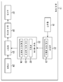
도 2는 표시부의 보다 상세한 구성예를 나타내는 도면이다.
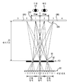
도 3은 4 시점의 시차 화상의 입체 표시에 대하여 설명하는 도면이다.
도 4는 개구부의 각 부의 설계에 대하여 설명하는 도면이다.
도 5는 적시거리의 절반 거리로부터의 시청에 대하여 설명하는 도면이다.
도 6은 유저에 의해 관찰되는 화소의 채널에 대하여 설명하는 도면이다.
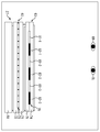
도 7은 각 채널에의 시차 화상의 할당에 대하여 설명하는 도면이다.
도 8은 연속 블록 영역의 경계 위치에 대하여 설명하는 도면이다.
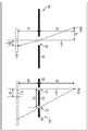
도 9는 시인 위치의 산출에 대하여 설명하는 도면이다.
도 10은 시인 위치의 산출에 대하여 설명하는 도면이다.
도 11은 시차 화상의 할당에 대하여 설명하는 도면이다.
도 12는 경계 위치의 산출에 대하여 설명하는 도면이다.
도 13은 입체 표시할 수 없는 시점 위치에 대하여 설명하는 도면이다.
도 14는 입체 표시 가능한 영역에 대하여 설명하는 도면이다.
도 15는 표시 처리를 설명하는 흐름도이다.
도 16은 시차 화상의 할당에 대하여 설명하는 도면이다.
도 17은 표시 시스템의 구성예를 나타내는 도면이다.
도 18은 6 시점용 표시부에 있어서의 시차 화상의 할당에 대하여 설명하는 도면이다.
도 19는 컴퓨터의 구성예를 나타내는 도면이다.1 is a diagram illustrating a configuration example of an embodiment of a display device.
2 is a diagram illustrating a more detailed configuration example of the display unit.
It is a figure explaining the stereoscopic display of the parallax image from four viewpoints.
It is a figure explaining the design of each part of an opening part.
It is a figure explaining the viewing from half distance of timely distance.
It is a figure explaining the channel of the pixel observed by a user.
It is a figure explaining the assignment of the parallax image to each channel.
It is a figure explaining the boundary position of a continuous block area | region.
It is a figure explaining the calculation of the visual recognition position.
It is a figure explaining the calculation of the visual recognition position.
It is a figure explaining the assignment of a parallax image.
It is a figure explaining the calculation of a boundary position.
It is a figure explaining the viewpoint position which cannot be stereoscopically displayed.
It is a figure explaining the three-dimensional display area.
15 is a flowchart for explaining display processing.
It is a figure explaining the assignment of a parallax image.
It is a figure which shows the structural example of a display system.
It is a figure explaining the assignment of the parallax image in a 6-view display part.
19 is a diagram showing a configuration example of a computer.
이하, 도면을 참조하여, 본 기술을 적용한 실시 형태에 대하여 설명한다.EMBODIMENT OF THE INVENTION Hereinafter, with reference to drawings, embodiment which applied this technique is described.
<제1 실시 형태>≪ First Embodiment >
[표시 장치의 구성예][Configuration example of display device]
도 1은, 본 기술을 적용한 표시 장치의 일 실시 형태의 구성예를 나타내는 도면이다.1 is a diagram illustrating a configuration example of an embodiment of a display device to which the present technology is applied.
이 표시 장치(11)는 복수 시점의 시차 화상을 이용하여 피사체를 입체 표시시키는 표시 장치이다. 표시 장치(11)는 촬상부(21), 검출부(22), 할당 제어부(23), 기록부(24), 생성부(25), 표시 제어부(26) 및 표시부(27)로 구성된다.The
촬상부(21)는 표시 장치(11) 주변의 유저의 화상, 예를 들어 표시부(27)의 거의 정면으로부터, 표시부(27)에 표시된 화상을 관찰하는 유저의 화상(이하, '주변 화상'이라 함)을 촬상하고, 검출부(22)에 공급한다.The
검출부(22)는 촬상부(21)로부터 공급된 주변 화상으로부터 유저의 눈을 검출하고, 그 검출 결과를 할당 제어부(23)에 공급한다. 또한, 검출부(22)는 시점 위치 산출부(31)를 구비하고 있으며, 시점 위치 산출부(31)는 주변 화상에 기초하여, 표시부(27)에 대한 유저의 시점 위치를 산출하고, 할당 제어부(23)에 공급한다.The
할당 제어부(23)는 검출부(22)로부터의 검출 결과나 유저의 시점 위치에 기초하여, 표시부(27)의 표시면 위의 각 영역에, 복수의 시차 화상을 할당한다. 할당 제어부(23)는 판정부(32), 시인 위치 산출부(33), 및 경계 위치 산출부(34)를 구비하고 있다.The
판정부(32)는 검출부(22)로부터의 시점 위치에 기초하여, 복수의 시차 화상에 의한 피사체의 입체 표시(3D 표시)가 가능한지 여부를 판정하고, 할당 제어부(23)는 그 판정 결과에 따라서 생성부(25)에서의 화상 생성을 제어한다.The
시인 위치 산출부(33)는 검출부(22)로부터의 시점 위치에 기초하여, 유저에 의해 시인되고 있는 표시부(27)의 표시면 위의 화소 내의 위치를 시인 위치로서 산출한다. 경계 위치 산출부(34)는 시인 위치에 기초하여, 표시부(27)의 표시면 위의 각 영역에 복수의 시차 화상을 할당한다.The visual recognition
기록부(24)는 입체 화상을 구성하는 복수의 시차 화상을 기록하고 있으며, 필요에 따라서 시차 화상을 생성부(25)에 공급한다. 생성부(25)는 할당 제어부(23)의 제어에 따라서, 기록부(24)로부터의 시차 화상에 기초하여, 그들 시차 화상을 공간 분할하여 합성한 합성 화상을 생성하고, 표시 제어부(26)에 공급한다. 또한, 생성부(25)는 할당 제어부(23)의 제어에 따라서, 기록부(24)로부터의 시차 화상 중 어느 하나를, 그대로 표시 제어부(26)에 공급한다.The
표시 제어부(26)는 생성부(25)로부터의 합성 화상을 표시부(27)에 공급하여 표시시킴으로써, 시차 화상 위의 피사체를 입체 표시시키거나, 생성부(25)로부터의 시차 화상을 표시부(27)에 공급하여 표시시키거나 한다. 표시부(27)는 나안 방식에 의해 입체 화상을 표시 가능한 액정 표시 패널 등을 포함하고, 표시 제어부(26)로부터 공급된 합성 화상이나 시차 화상을 표시한다.The
[표시부의 구성예][Configuration example of the display unit]
또한, 도 1의 표시부(27)는 예를 들어 도 2에 도시한 바와 같이 구성된다.In addition, the
즉, 표시부(27)는 백라이트(61), 광 변조 패널(62), 및 배리어 소자(63)로 구성된다.That is, the
백라이트(61)는, 예를 들어 LED(Light Emitting Diode) 광원이나 도광판 등을 포함하며, 화상을 표시시키기 위한 광을 사출하고, 광 변조 패널(62)에 입사시킨다.The
광 변조 패널(62)은, 예를 들어 액정층이나 R, G, B의 각 색의 컬러 필터 등을 포함하며, 백라이트(61)로부터 입사한 광을 투과시킴으로써, 화상을 표시시킨다. 이때, 광 변조 패널(62)은 광 변조 패널(62)에 설치된 화소마다, 광의 투과율을 변화시킴으로써, 화상의 각 화소의 계조 표시를 행한다.The
보다 상세하게는, 광 변조 패널(62)은 투명 기판(71), 투명 기판(72), 및 액정층(73)을 구비하고 있으며, 액정층(73)은 서로 대향하도록 배치된 평판 형상의 투명 기판(71)과 투명 기판(72) 사이에 형성되어 있다. 액정층(73)에는, 화상이 표시되는 화소로서의 투과부가 형성되어 있으며, 화상의 표시 시에 있어서, 투명 기판(71)과 투명 기판(72)에 설치되어 있는 전극에 전압이 인가되면, 백라이트(61)로부터 투과부에 입사한 광의 투과율이 인가된 전압에 따라서 변화한다.More specifically, the
또한, 배리어 소자(63)는 편광판이나 스위치 액정층 등을 포함하며, 광 변조 패널(62)로부터 입사한 광의 일부를 차광하고, 남은 일부를 투과시킴으로써, 각 시차 화상을 광학적으로 분리시킨다. 배리어 소자(63)는 투명 기판(74), 투명 기판(75), 및 스위치 액정층(76)을 구비하고 있으며, 스위치 액정층(76)은 서로 대향하도록 배치된 평판 형상의 투명 기판(74)과 투명 기판(75) 사이에 형성되어 있다.In addition, the
투명 기판(74)과 투명 기판(75)에는, 전극이 형성되어 있으며, 이들 전극의 일부 또는 전부에 전압이 인가되면, 스위치 액정층(76) 내의 액정 분자의 배향 방향이 변화하고, 이에 의해, 스위치 액정층(76)에는 패럴랙스 배리어가 형성된다.Electrodes are formed on the
도 2의 예에서는, 광 변조 패널(62)로부터 입사한 광을 투과시키는 개구부(81-1) 내지 개구부(81-3)와, 광 변조 패널(62)로부터 입사한 광을 차광하는 차폐부(82-1) 내지 차폐부(82-3)를 포함하여 이루어지는 패럴랙스 배리어가, 스위치 액정층(76)에 형성되어 있다.In the example of FIG. 2, the openings 81-1 to 81-3 through which light incident from the
또한, 이하, 개구부(81-1) 내지 개구부(81-3)를 특별히 구별할 필요가 없는 경우, 단순히 '개구부(81)'라고도 하고, 차폐부(82-1) 내지 차폐부(82-3)를 특별히 구별할 필요가 없는 경우, 단순히 '차폐부(82)'라고도 한다. 또한, 피사체를 입체 표시하는 합성 화상이 광 변조 패널(62)에 표시되는 경우에는, 배리어 소자(63)에 패럴랙스 배리어가 형성되지만, 2D 화상인 시차 화상이 광 변조 패널(62)에 표시되는 경우에는, 배리어 소자(63)에 패럴랙스 배리어는 형성되지 않는다.In addition, below, when it is not necessary to distinguish between the opening part 81-1 and the opening part 81-3 especially, it is also only called the "opening
도 2와 같이 구성되는 표시부(27)에서는, 유저는 배리어 소자(63) 측으로부터 광 변조 패널(62)에 표시되는 화상을 관찰한다. 특히, 합성 화상의 표시 시에는, 백라이트(61)로부터 사출되고, 광 변조 패널(62) 및 배리어 소자(63)를 투과한 광이, 유저의 우안 ER 또는 좌안 EL에 입사한다. 이때, 유저의 우안 ER과 좌안 EL에는, 배리어 소자(63)에서 분리된 서로 다른 광이 입사하므로, 우안 ER과 좌안 EL에서 서로 시차를 갖는 상이한 시차 화상이 관찰된다.In the
또한, 도 2에서는, 시차 화상을 광학적으로 분리하는 분리부의 예로서 배리어 소자(63)에 대하여 설명하였지만, 분리부는 패럴랙스 배리어에 한하지 않고, 렌티큘러 렌즈 등으로 되어도 된다. 또한, 분리부로서의 패럴랙스 배리어는, 가변식의 배리어에 한하지 않고, 차폐판 등에 개구부가 설치된 고정식 배리어로 되어도 된다.In addition, although the
또한, 배리어 소자(63)는 광 변조 패널(62)과 백라이트(61) 사이에 배치되도록 하여도 된다.In addition, the
[적시거리로부터의 입체 화상의 관찰에 대하여][Observation of three-dimensional image from timely distance]
이제, 표시 장치(11)에 4개의 서로 다른 시점의 시차 화상을 합성하여 얻어진 합성 화상을 표시하고, 유저가 표시부(27)로부터 소정의 거리만큼 이격된 위치로부터 표시부(27)를 관찰하는 경우에 대하여 생각한다.Now, when the synthesized image obtained by combining the disparity images of four different viewpoints is displayed on the
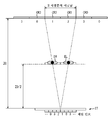
예를 들어 도 3에 도시한 바와 같이, 유저의 우안 ER과 좌안 EL의 중간 위치를 유저의 시점 위치로 하고, 유저의 시점 위치가 배리어 소자(63)의 표면으로부터 거리 Z0(이하, '적시거리 Z0'이라 함)만큼 이격된 위치에 있다고 하자. 또한, 우안 ER과 좌안 EL의 거리(이하, '눈간 거리 E'라 함)가 65㎜인 것으로 한다. 또, 일반적인 어른의 눈간 거리는 약 65㎜이다.For example, as shown in FIG. 3, the intermediate position between the user's right eye ER and the left eye EL is the user's viewpoint position, and the user's viewpoint position is a distance Z0 (hereinafter, 'timely distance') from the surface of the
또한, 광 변조 패널(62)의 표시면 위에는, 4개의 시점의 시차 화상 각각이 표시되는 화소인, 채널 CH0 내지 채널 CH3의 4개의 각 채널 화소를 포함하여 이루어지는 블록 영역이, 도면에서 가로 방향으로 나란히 형성되어 있다.In addition, on the display surface of the
또한, 도 3에서는, 광 변조 패널(62)에 있어서의 1개의 사각형은 1개의 화소를 나타내고 있으며, 그들 화소의 도면에서 하측에는, 각 화소가 속하는 채널 번호가 나타나 있다. 또한, 도면에서 가로 방향 및 세로 방향을 각각 x 방향 및 y 방향이라 하고, x 방향 및 y 방향에 수직인 방향을 z 방향이라 한다. 여기서, x 방향은 유저의 우안 ER과 좌안 EL이 나란한 방향, 즉 광 변조 패널(62)에 표시되는 시차 화상의 시차 방향이며, y 방향은 광 변조 패널(62)의 표시면과 수직인 방향이다.In addition, in FIG. 3, one square in the
도 3에서는, 블록 영역 내에 있어서, 도면 중, 우측에서 좌측까지 채널 CH0 화소, 채널 CH1 화소, 채널 CH2 화소 및 채널 CH3 화소가 순서대로 배열되어 있다.In FIG. 3, in the block area, channel CH0 pixels, channel CH1 pixels, channel CH2 pixels, and channel CH3 pixels are arranged in order from the right to the left in the figure.
또한, 블록 영역에 있어서, 예를 들어 z 방향에는, 동일한 채널 화소가 배열되어 있다. 그리고, 광 변조 패널(62)의 표시면 위에는, 이러한 블록 영역이 x 방향으로 연속하여 배열되어 있다. 이하, 1개의 블록 영역 내에 있어서, 동일한 채널 화소를 포함하여 이루어지는 영역을 '채널 영역'이라고도 칭하기로 한다.In the block region, the same channel pixel is arranged in the z-direction, for example. On the display surface of the
또한, 배리어 소자(63)에는, 1개의 블록 영역에 대하여, 패럴랙스 배리어를 구성하는 1개의 개구부(81)가 설치되어 있다. 따라서, 시점 P0 내지 시점 P3의 시차 화상 각각이, 채널 CH0 내지 채널 CH3 화소의 각각에 표시되면, 그들 각 시점의 시차 화상은, 배리어 소자(63)에 의해 광학적으로 분리된다.The
즉, 배리어 소자(63)로부터 적시거리 Z0만큼 이격된 xz 평면 위에 있어서, 채널 CH3의 각 화소로부터 사출되고, 개구부(81)를 통과한 광은 영역 CR0에 도달하고, 채널 CH2의 각 화소로부터 사출되고, 개구부(81)를 통과한 광은 영역 CR1에 도달한다. 마찬가지로, 채널 CH1의 각 화소로부터 사출되어, 개구부(81)를 통과한 광은 영역 CR2에 도달하고, 채널 CH0의 각 화소로부터 사출되어, 개구부(81)를 통과한 광은 영역 CR3에 도달한다.That is, on the xz plane spaced apart from the
또한, 도면 중, 상측에 있어서 x 방향으로 나란한 숫자 0 내지 숫자 3은 그 숫자가 기재된 영역에 도달하는 광이 방출된 화소의 채널 번호를 나타내고 있다. 예를 들어, 영역 CR0의 도면 중, 상측에 기재된 숫자 「3」은, 영역 CR0에는, 채널 CH3 화소로부터의 광이 도달하는 것을 나타내고 있다.In the figure,
여기서, 영역 CR0 내지 영역 CR3의 각 영역의 x 방향의 폭은 눈간 거리 E(=65㎜)로 된다. 따라서, 배리어 소자(63)로부터 적시거리 Z0만큼 이격된 xz 평면 위에 위치하는 유저의 좌우 눈에는, 1 시점분만큼 어긋난 서로 다른 시점의 시차 화상이 관찰되게 된다. 예를 들어, 도 3의 예에서는, 유저의 우안 ER은 영역 CR2 안에 위치하고, 좌안 EL은 영역 CR1 안에 위치하기 때문에, 유저의 우안 ER 및 좌안 EL에는, 각각 시점 P1의 시차 화상 및 시점 P2의 시차 화상이 관찰되게 된다. 그 결과, 유저에게 그들 시차 화상 위의 피사체가 입체적으로 지각된다.Here, the width | variety of the x direction of each area | region of area | region CR0-area | region CR3 is set as the eye distance E (= 65 mm). Therefore, parallax images of different viewpoints shifted by one viewpoint are observed in the left and right eyes of the user located on the xz plane spaced apart from the
또한, 예를 들어 이 상태로부터 유저의 시점 위치가 도면 중, 좌측 방향으로 눈간 거리 E만큼 이동하면, 유저의 우안 ER 및 좌안 EL에는, 각각 시점 P0의 시차 화상, 및 시점 P1의 시차 화상이 관찰되게 된다.For example, when the user's viewpoint position moves from the state to the leftward distance E in the figure, the parallax image of the viewpoint P0 and the parallax image of the viewpoint P1 are observed in the right eye ER and the left eye EL of the user, respectively. Will be.
[패럴랙스 배리어의 설계에 대하여][Design of Parallax Barrier]
이와 같이, 적시거리 Z0만큼 이격된 위치로부터 표시부(27)를 관찰하는 유저에게, 각 개구부(81)를 통하여 동일한 채널 화소가 시인되도록 하기 위해서는, 개구부(81) 사이의 거리나, 개구부(81)로부터 광 변조 패널(62)까지의 거리 등을 적절하게 정할 필요가 있다.Thus, in order for the user who observes the
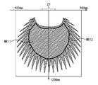
예를 들어, 도 3의 예에서는, 유저의 좌우 눈에는, 광 변조 패널(62) 위의 서로 인접하는 화소가 개구부(81)를 통하여 관찰된다. 이러한 경우, 적시거리Z0=900㎜라고 하면, 도 4에 도시한 바와 같이, 개구부(81)로부터 광 변조 패널(62)까지의 거리 D1과, 개구부(81) 사이의 거리 D2가 정해진다. 또한, 도면 중, 가로 방향 및 세로 방향은 x 방향 및 y 방향을 나타내고 있다.For example, in the example of FIG. 3, pixels adjacent to each other on the
도 4의 좌측에 있어서, 개구부(81)의 중심을 통과하는 y 방향에 평행한 직선을 직선 A11로 하고, 유저의 한쪽 눈이 점 PE11에 있다고 하자. 여기서, 점 PE11은, 직선 A11로부터 x 방향으로 거리 X1만큼 이격되어 있으면서, 개구부(81)로부터 y 방향으로 적시거리 Z0만큼 이격된 위치에 있다. 또한, 배리어 소자(63)의 도면 중, 하측에 있는 각 사각형은, 광 변조 패널(62) 위의 화소를 나타내고 있다.In the left side of FIG. 4, suppose the straight line parallel to the y direction passing through the center of the
예를 들어, 도면 중, 좌측에 도시한 바와 같이 유저의 눈의 위치 PE11로부터, 개구부(81)를 통하여 1개의 화소 G11이 시인된다고 하자. 각 화소 간 거리를 D3라고 하면, 이 화소 G11의 중심은, 직선 A11로부터 (D3)/2만큼 이격된 위치에 있다.For example, suppose that one pixel G11 is visually recognized through the opening
여기서, 배리어 소자(63)로부터 광 변조 패널(62)의 각 화소까지의 사이가 유리재로 채워져 있으며, 점 PE11로부터 이 유리재로 진행하는 광의 상대 굴절률이k1이라 하면, X1:Z0=(D3)/2:D1/k1이므로, D1=Z0×((D3)/2)×k1/X1이 된다. 예를 들어, Z0=900㎜, D3=0.05435㎜, X1=32.5㎜, k1=1.5라 하면, 이들 값으로부터 D1=900×((0.05435)/2)×1.5/32.5=1.1288㎜로 된다.Here, assuming that the distance from the
또한, 도면 중, 우측에 도시한 바와 같이, 유저의 눈이 직선 A11 위의 점PE12에 있다고 하자. 이 경우, 광 변조 패널(62)은 4 시점용이기 때문에, 점 PE12로부터 도면 중, 좌측의 개구부(81)를 통하여 보이는 광 변조 패널(62)의 위치와, 그 개구부(81)의 우측에 인접하는 개구부(81)를 통하여 보이는 광 변조 패널(62)의 위치는 4 화소분만큼 이격되어 있을 것이다.In addition, as shown to the right in the figure, it is assumed that the eyes of the user are at the point PE12 on the straight line A11. In this case, since the
따라서, Z0:D2=(Z0+(D1/k1)):4×D3이 성립하므로, D2=Z0×D3×4/(Z0+(D1/k1))에 의해, 개구부(81) 사이의 거리 D2가 구해진다. 여기서, Z0=900㎜, D3=0.05435㎜, D1=1.1288㎜, k1=1.5라 하면, 이들 값으로부터 D2=900×0.05435×4/(900+(1.1288/1.5))=0.2172184㎜로 된다.Therefore, since Z0: D2 = (Z0 + (D1 / k1)): 4 × D3 holds, the distance D2 between the
[적시거리의 절반 거리로부터의 관찰에 대하여][Observation from half distance of timely distance]
그런데, 예를 들어 도 5에 도시한 바와 같이, 유저의 시점 위치가, 표시부(27)로부터 y 방향으로 전술한 적시거리의 절반 거리 Z0/2만큼 이격된 위치에 있다고 하자.By the way, as shown, for example in FIG. 5, suppose that the user's viewpoint position is spaced apart from the
이 경우, 표시부(27)의 광 변조 패널(62) 위의 1점으로부터의 광에는, 유저의 우안 ER의 위치를 통과하여 영역 CR2의 좌측 단부에 도달하는 광과, 좌안 EL의 위치를 통과하여 영역 CR1의 우측 단부에 도달하는 광이 있다. 표시부(27)로부터 적시거리 Z0만큼 이격된 xz 평면 위에 있어서, 이들 광의 도달점 간의 x 방향의 거리는 눈간 거리 E의 2배 거리로 된다. 즉, 2 시점분만큼 어긋남이 발생하고 있다.In this case, the light from one point on the
그로 인해, 예를 들어 유저의 우안 ER로부터 소정의 개구부(81)를 통하여 블록 영역의 채널 CH1 화소가 보이고 있는 상태에서는, 유저의 좌안 EL로부터는, 동일한 개구부(81)를 통하여 블록 영역의 채널 CH3 화소가 보이게 된다.Therefore, for example, in the state where the channel CH1 pixel of the block region is seen from the right eye ER of the user through the
또한, 유저의 시점 위치가 동일하여도, 예를 들어 도 6에 도시한 바와 같이, 유저가 적시거리 Z0의 절반 거리로부터 표시부(27)를 관찰하면, 표시부(27)의 각 영역(블록 영역)에 의해, 유저의 눈의 위치를 통과하는 광이 도달하는 xz 평면 위의 영역이 서로 다르다. 또한, 도 6에 있어서는, 도 3에 있어서의 경우와 마찬가지로, 표시부(27)로부터 적시거리 Z0만큼 이격된 xz 평면 위의 영역에는, 그 영역에 도달하는 광이 방출된 화소의 채널 번호가 기재되어 있다.In addition, even if the user's viewpoint position is the same, for example, as shown in FIG. 6, when the user observes the
예를 들어, 도 6의 상태에서는, 화살표 Q11로 나타낸 바와 같이, 광 변조 패널(62)의 도면 중, 좌측 단부에 있는, 몇 개의 블록 영역을 포함하여 이루어지는 영역에서는, 유저의 우안 ER에는 개구부(81)를 통하여 채널 CH2 화소가 시인되게 된다. 즉 채널 CH2 화소로부터 방출된 광이, 개구부(81)를 통하여 유저의 우안 ER에 입사한다.For example, in the state of FIG. 6, as indicated by the arrow Q11, in the region including some block regions at the left end of the
또한, 광 변조 패널(62)의 도면 중, 좌측 단부로부터 2번째에 있는, 몇 개의 블록 영역을 포함하여 이루어지는 영역에서는, 유저의 우안 ER에는 개구부(81)를 통하여 채널 CH1 화소가 시인된다. 또한, 광 변조 패널(62)의 도면 중, 좌측 단부로부터 3번째 및 우측 단부에 있는, 몇 개의 블록 영역을 포함하여 이루어지는 영역에서는, 유저의 우안 ER에는 개구부(81)를 통하여, 각각 채널 CH0 화소 및 채널 CH3 화소가 시인된다.Moreover, in the area | region which consists of several block area | regions which are 2nd from the left edge part in the figure of the
또한, 화살표 Q11로 나타내는 사각형은, 광 변조 패널(62) 위의 각 영역을 나타내고 있으며, 그들 영역 내의 숫자는, 유저의 우안 ER에 의해 시인되는 화소의 채널 번호를 나타내고 있다. 또한, 각 영역을 나타내는 사각형의 도면 중, 상측의 곡선은, 각 영역의 화소로부터 방출되고, 유저의 우안 ER에 도달하는 광의 휘도 분포를 나타내고 있다. 예를 들어, 광 변조 패널(62) 위의 채널 번호 「3」이 기재된 영역의 좌측 단부에서는, 채널 CH3 화소로부터의 광과 채널 CH0 화소로부터의 광이, 동일한 휘도로 유저의 우안 ER에 입사한다.In addition, the square shown by the arrow Q11 has shown each area | region on the
마찬가지로, 화살표 Q12로 나타낸 바와 같이, 광 변조 패널(62)의 도면 중, 좌측 단부에 있는, 몇 개의 블록 영역을 포함하여 이루어지는 영역에서는, 유저의 좌안 EL에는 개구부(81)를 통하여 채널 CH0 화소가 시인된다.Similarly, as indicated by arrow Q12, in the region including some block regions at the left end of the
또한, 광 변조 패널(62)의 도면 중, 좌측 단부로부터 2번째로 있는, 몇 개의 블록 영역을 포함하여 이루어지는 영역에서는, 유저의 좌안 EL에는 개구부(81)를 통하여 채널 CH3 화소가 시인된다. 또한, 광 변조 패널(62)의 도면 중, 좌측 단부로부터 3번째 및 우측 단부에 있는, 몇 개의 블록 영역을 포함하여 이루어지는 영역에서는, 유저의 좌안 EL에는 개구부(81)를 통하여, 각각 채널 CH2 화소 및 채널 CH1 화소가 시인된다.Moreover, in the area | region which consists of several block area | regions which are 2nd from a left edge part in the figure of the
또한, 화살표 Q12로 나타내는 사각형은, 광 변조 패널(62) 위의 각 영역을 나타내고 있으며, 그들 영역 내의 숫자는, 유저의 좌안 EL에 의해 시인되는 화소의 채널 번호를 나타내고 있다. 또한, 각 영역을 나타내는 사각형의 도면 중, 상측의 곡선은, 각 영역의 화소로부터 방출되고, 유저의 좌안 EL에 도달하는 광의 휘도 분포를 나타내고 있다.In addition, the square shown by the arrow Q12 has shown each area | region on the
[표시 장치에 의한 화상의 표시에 대하여][Display of image by display device]
이와 같이, 적시거리 Z0의 약 절반 거리로부터 표시부(27)를 관찰하면, 유저의 우안과 좌안에 의해 시인되는 블록 영역 내의 화소는, 2 화소분의 거리만큼 이격된 위치에 있는 화소가 된다.Thus, when the
그로 인해, 우안용과 좌안용 시차 화상을 표시부(27)에 표시시키는 경우에, 각 채널 화소에 적절하게 우안용 또는 좌안용 시차 화상을 표시시켜서, 유저가 적시거리 Z0의 약 절반 거리로부터 시차 화상을 관찰하면, 크로스토크의 발생을 억제할 수 있다.Therefore, when displaying the right-eye and left-eye parallax image on the
예를 들어, 도 3에 도시한 상태에서는, 유저의 우안 ER은 채널 CH1 화소를 관찰하고 있으며, 유저의 좌안 EL은 채널 CH2 화소를 관찰하고 있다. 이 상태로부터, 예를 들어 유저가 도 3에서, 우측 방향으로 조금 이동하였다고 하자. 그렇게 하면, 채널 CH1 화소와 채널 CH2 화소는 서로 인접하고 있기 때문에, 유저의 우안 ER에는, 지금까지 보이고 있던 채널 CH1 화소뿐만 아니라, 좌안 EL로 보고 있던 채널 CH2 화소도 보여, 크로스토크가 발생한다. 즉, 좌우의 시차 화상 위의 피사체가 2겹으로 보이게 된다.For example, in the state shown in FIG. 3, the right eye ER of the user observes the channel CH1 pixel, and the left eye EL of the user observes the channel CH2 pixel. From this state, for example, assume that the user has moved slightly in the right direction in FIG. 3. In this case, since the channel CH1 pixel and the channel CH2 pixel are adjacent to each other, not only the channel CH1 pixel seen so far but also the channel CH2 pixel viewed by the left eye EL appear in the right eye ER of the user, and crosstalk occurs. That is, the subjects on the left and right parallax images appear in two layers.
이에 반하여, 예를 들어 도 6에 도시한 상태에서, 광 변조 패널(62)의 도면 중, 중앙으로부터 약간 좌측에 있는 블록 영역의 채널 CH1에 우안용 시차 화상을 표시시키고, 동일한 블록 영역의 채널 CH3에 좌안용 시차 화상을 표시시켰다고 하자.On the other hand, in the state shown in FIG. 6, for example, in the figure of the
이 경우, 유저의 우안 ER에는 우안용 시차 화상이 관찰되고, 유저의 좌안 EL에는 좌안용 시차 화상이 관찰되게 된다. 이 상태로부터 유저가 도면 중, 우측 방향에 조금 이동하여도, 채널 CH1과 채널 CH3 화소는 2 화소분만큼 이격되어 있으므로, 유저의 우안 ER에 좌안용 시차 화상이 관찰되는 경우는 없다.In this case, a parallax image for the right eye is observed in the right eye ER of the user, and a parallax image for the left eye is observed in the left eye EL of the user. From this state, even if the user moves slightly in the right direction in the figure, the channel CH1 and the channel CH3 pixels are separated by two pixels, so that the left eye parallax image is not observed in the right eye ER of the user.
또한, 유저의 시점 위치의 이동에 따라서, 크로스토크가 발생하기 전에 각 채널 화소에 있어서의 시차 화상의 표시 전환을 행하면, 각 영역에서의 좌우 시차 화상의 표시 전환을 유저가 느낄 수 없어, 보다 자연스러운 화상의 제시가 가능해진다.In addition, when the user switches the display position of the parallax image in each channel pixel before crosstalk occurs, the user cannot feel the display switching of the left and right parallax images in each area, and the user is more natural. Images can be presented.
이와 같이, 유저의 시점 위치에 따라서, 각 채널 화소에 적절하게 우안용 또는 좌안용 시차 화상을 표시시켜, 유저가 통상의 적시거리인 약 절반 거리에서 관찰하면, 크로스토크의 발생을 억제하여, 보다 고품질의 화상을 제시하는 것이 가능하다. 이하, 이러한 입체 화상의 표시 방식을, '반 시거리 표시 방식'이라 칭하기로 한다.In this way, if the right eye or left eye parallax image is appropriately displayed on each channel pixel according to the user's viewpoint position, and the user observes at about half distance which is a normal timely distance, the occurrence of crosstalk is suppressed, It is possible to present high quality images. Hereinafter, the display system of such a three-dimensional image will be referred to as a "half viewing distance display system".
[반 시거리 표시 방식에 있어서의 표시 제어에 대하여][Display Control in Half Viewing Distance Display Method]
다음으로, 좌안용과 우안용 시차 화상에 기초하여, 반 시거리 표시 방식에 의해 입체 화상을 표시시키는 구체적인 제어에 대하여 설명한다.Next, the specific control which displays a stereoscopic image by the half viewing distance display system based on the parallax image for left eye and right eye is demonstrated.
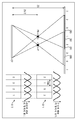
예를 들어, 도 7에 도시한 바와 같이, 유저가 소정의 위치에 있는 경우에, 유저의 우안에 광 변조 패널(62)의 도면 중, 좌측 단부의 영역 B11 안의 채널 CH2 화소가 시인되었다고 하자. 또한, 광 변조 패널(62)의 영역 B12, 영역 B13 및 영역 B14에서는, 각각 유저의 우안에 의해 채널 CH1 화소, 채널 CH0 화소 및 채널 CH3 화소가 시인되었다고 하자.For example, as shown in FIG. 7, suppose that the channel CH2 pixel in the area B11 of the left end is visually recognized in the figure of the
이 경우, 광 변조 패널(62)의 영역 B11 내지 영역 B14에서는, 유저의 좌안에는, 각각 채널 CH0 화소, 채널 CH3 화소, 채널 CH2 화소 및 채널 CH1 화소가 시인된다.In this case, in the areas B11 to B14 of the
또한, 이들 영역 B11 내지 영역 B14는, 복수의 블록 영역을 포함하여 이루어지는 영역이다. 이러한 상태에서, 표시 장치(11)는 영역 B11 내지 영역 B14에 대하여, 그들 영역 내의 블록 영역 중, 유저에 의해 시인되는 화소로부터의 광의 휘도가 가장 높아지는 블록 영역의 위치를 특정하고, 그들 위치를 경계 위치 LB11 내지 경계 위치 LB14라고 하자.These areas B11 to B14 are areas including a plurality of block areas. In such a state, the
즉, 경계 위치 LB11은, 영역 B11 안의 블록 영역 중, 시인되는 화소로부터의 광의 휘도가 가장 높은 블록 영역의 위치이다. 마찬가지로, 경계 위치 LB12 내지 경계 위치 LB14 각각은, 영역 B12 내지 영역 B14 각각에 있는 블록 영역 중, 시인되는 화소로부터의 광의 휘도가 가장 높은 블록 영역 각각의 위치이다.In other words, the boundary position LB11 is the position of the block region having the highest luminance of light from the visible pixel among the block regions in the region B11. Similarly, each of the boundary positions LB12 to LB14 is a position of each of the block regions having the highest luminance of light from the visible pixel among the block regions in each of the regions B12 to B14.
이와 같이 하여 경계 위치가 특정되면, 표시 장치(11)는 광 변조 패널(62) 위의 경계 위치 LB11 내지 경계 위치 LB14에 의해 분할되는 각 영역에 대하여, 각 채널에의 좌우 시차 화상의 할당을 행한다.When the boundary position is specified in this manner, the
구체적으로는, 영역 B11의 좌측 단부로부터 경계 위치 LB11까지의 사이에 있는 각 블록 영역에서는, 채널 CH2와 채널 CH3 화소에 우안용 시차 화상이 할당되고, 채널 CH0과 채널 CH1 화소에 좌안용 시차 화상이 할당된다.Specifically, in each block area between the left end of the area B11 and the boundary position LB11, a right eye parallax image is assigned to the channel CH2 and channel CH3 pixels, and a left eye parallax image is assigned to the channel CH0 and channel CH1 pixels. Is assigned.
마찬가지로, 경계 위치 LB11로부터 경계 위치 LB12까지의 사이에 있는 각 블록 영역에서는, 채널 CH1과 채널 CH2 화소에 우안용 시차 화상이 할당되고, 채널 CH0과 채널 CH3 화소에 좌안용 시차 화상이 할당된다. 또한, 경계 위치 LB12로부터 경계 위치 LB13까지의 사이에 있는 각 블록 영역에서는, 채널 CH0과 채널 CH1 화소에 우안용 시차 화상이 할당되고, 채널 CH2와 채널 CH3 화소에 좌안용 시차 화상이 할당된다.Similarly, in each block area between the boundary position LB11 and the boundary position LB12, the right eye parallax image is allocated to the channel CH1 and channel CH2 pixels, and the left eye parallax image is allocated to the channel CH0 and channel CH3 pixels. In addition, in each block area between the boundary position LB12 and the boundary position LB13, the right eye parallax image is allocated to the channel CH0 and the channel CH1 pixels, and the left eye parallax image is allocated to the channel CH2 and channel CH3 pixels.
또한, 경계 위치 LB13으로부터 경계 위치 LB14까지의 사이에 있는 각 블록 영역에서는, 채널 CH0과 채널 CH3 화소에 우안용 시차 화상이 할당되고, 채널 CH1과 채널 CH2 화소에 좌안용 시차 화상이 할당된다. 또한, 경계 위치 LB14로부터 영역 B14의 우측 단부까지의 사이에 있는 각 블록 영역에서는, 채널 CH2와 채널 CH3 화소에 우안용 시차 화상이 할당되고, 채널 CH0과 채널 CH1 화소에 좌안용 시차 화상이 할당된다.In addition, in each block area between the boundary position LB13 and the boundary position LB14, the right eye parallax image is allocated to the channel CH0 and the channel CH3 pixels, and the left eye parallax image is allocated to the channel CH1 and channel CH2 pixels. In addition, in each block area between the boundary position LB14 and the right end of the area B14, the right eye parallax image is allocated to the channel CH2 and the channel CH3 pixels, and the left eye parallax image is allocated to the channel CH0 and the channel CH1 pixels. .
그리고, 이러한 블록 영역에서의 각 채널에의 시차 화상의 할당에 따라서 합성 화상이 생성되고, 생성된 합성 화상이 광 변조 패널(62)에 표시된다.Then, a composite image is generated in accordance with the assignment of the parallax image to each channel in such a block area, and the generated synthesized image is displayed on the
또한, 이 상태로부터 유저의 시점 위치가 이동하면, 각 블록 영역 내에서 유저에 의해 시인되는 화소의 채널이 변화하므로, 시점 위치의 변화에 추종하여 경계 위치 LB11 내지 경계 위치 LB14의 위치도 이동한다. 그리고, 경계 위치 LB11 내지 경계 위치 LB14의 이동에 따라서, 블록 영역 내의 각 채널 화소에 대한 시차 화상의 할당이 변경된다.In addition, when the viewpoint position of a user moves from this state, since the channel of the pixel visually recognized by the user in each block area | region changes, following the change of viewpoint position, the position of boundary position LB11-boundary position LB14 also moves. Then, in accordance with the movement of the boundary positions LB11 to LB14, the allocation of the parallax image to each channel pixel in the block region is changed.
또한, 이하, 광 변조 패널(62)에 있어서, 연속하여 배열하는 몇 개의 블록 영역을 포함하여 이루어지는 영역으로서, 동일한 채널 화소에 동일한 시차 화상이 할당되는 블록 영역을 포함하여 이루어지는 영역을, '연속 블록 영역'이라고도 칭하기로 한다.In addition, hereinafter, the
예를 들어, 도 7의 예에서는, 경계 위치 LB11로부터 경계 위치 LB12까지의 사이에 있는 각 블록 영역을 포함하여 이루어지는 영역이나, 경계 위치 LB12로부터 경계 위치 LB13까지의 사이에 있는 각 블록 영역을 포함하여 이루어지는 영역이 하나의 연속 블록 영역으로 된다. 즉, 도 7에서는, 경계 위치 LB11 내지 경계 위치 LB14 각각이, 연속 블록 영역의 경계로 된다.For example, in the example of FIG. 7, the area including each block area between the boundary position LB11 and the boundary position LB12, or each block area between the boundary position LB12 and the boundary position LB13 is included. The area formed consists of one continuous block area. That is, in Fig. 7, each of the boundary positions LB11 to LB14 serves as a boundary of the continuous block area.
연속 블록 영역의 경계 위치는, 전술한 바와 같이, 유저에 의해 시인되는 화소로부터의 광의 휘도가 가장 높아지는 블록 영역의 위치이지만, 예를 들어 도 8에 도시한 바와 같이 경계 위치에서는, 가장 휘도가 높은 화소와 서로 다른 채널 화소는, 상대적으로 가장 휘도가 낮아진다.As described above, the boundary position of the continuous block region is the position of the block region where the luminance of light from the pixel visually recognized by the user is the highest, but for example, as shown in FIG. 8, the boundary position of the continuous block region has the highest luminance. Channel pixels different from the pixels have the lowest luminance relatively.
또한, 도 8에 있어서, 횡축은 유저의 x 방향의 시점 위치를 나타내고 있으며, 종축은 그들 위치에 있어서의, 소정 블록 영역 내의 각 채널 화소로부터의 광의 투과율, 즉 각 채널 화소로부터의 광의 휘도를 나타내고 있다.In FIG. 8, the horizontal axis represents the viewpoint position in the x direction of the user, and the vertical axis represents the transmittance of the light from each channel pixel in the predetermined block region, that is, the brightness of the light from each channel pixel at those positions. have.
도 8은, 특정한 블록 영역에 주목한 경우에, 유저의 시점 위치가 각 위치에 있을 때, 유저의 눈에 입사하는 각 채널 화소로부터의 광의 휘도를 나타내고 있다. 도 8에서는, 이점쇄선, 일점쇄선, 점선 및 실선의 각각은, 채널 CH0 내지 채널 CH3 화소로부터의 광의 휘도를 나타내고 있다.8 shows the luminance of light from each channel pixel incident on the user's eye when the user's viewpoint position is at each position when attention is paid to a specific block area. In Fig. 8, each of the dashed-dotted line, the dashed-dotted line, the dotted line and the solid line represents the luminance of the light from the channel CH0 to channel CH3 pixels.
이 예에서는, 유저의 눈이 위치 LB21 내지 위치 LB24의 각각에 있는 경우에, 유저에 의해 관찰되는 소정의 화소로부터의 광의 휘도가 최대로 되어 있다. 그로 인해, 예를 들어 유저의 우안이 위치 LB22에 있는 경우, 주목하고 있는 블록 영역의 채널 CH1 화소의 거의 중앙이 유저의 우안에 관찰되므로, 이 블록 영역이 연속 블록 영역의 경계 위치로 된다.In this example, when the eyes of the user are in each of the positions LB21 to LB24, the luminance of the light from the predetermined pixel observed by the user is maximized. Therefore, for example, when the right eye of the user is in the position LB22, since the center of the channel CH1 pixel of the block region of interest is observed in the right eye of the user, this block region becomes the boundary position of the continuous block region.
따라서, 유저의 우안이 위치 LB22보다도 도면 중 약간 좌측에 있는 경우, 주목하고 있는 블록 영역에서는, 채널 CH0과 채널 CH1 화소에 우안용 시차 화상이 표시되게 된다. 그리고, 이 상태로부터 유저의 우안이 위치 LB22보다도 도면 중 약간 우측의 위치로 이동하면, 주목하고 있는 블록 영역에서는, 채널 CH1과 채널 CH2 화소에 우안용 시차 화상이 표시되게 된다.Therefore, when the user's right eye is slightly to the left of the drawing than the position LB22, the right eye parallax image is displayed in the channel CH0 and the channel CH1 pixels in the block region of interest. In this state, when the user's right eye moves to a position slightly to the right of the figure than the position LB22, the right eye parallax image is displayed in the channel CH1 and channel CH2 pixels in the block region of interest.
즉, 유저의 시점 위치의 이동에 수반하여, 주목하고 있는 블록 영역에서는, 우안용 시차 화상의 표시가, 채널 CH0과 채널 CH1로부터, 채널 CH1과 채널 CH2로 전환하게 된다. 즉, 유저의 시점 위치의 이동에 따라, 서로 다른 채널 화소로부터의 광이 유저의 우안에 의해 지각되게 된다.In other words, with the movement of the user's viewpoint position, the right eye disparity image is switched from channel CH0 and channel CH1 to channel CH1 and channel CH2 in the block region of interest. That is, as the user moves the viewpoint position, light from different channel pixels is perceived by the user's right eye.
그러나, 위치 LB22 근방에서는, 채널 CH1 화소의 휘도에 비하여, 다른 채널 CH0과 채널 CH2 화소의 휘도가 상대적으로 가장 낮게 되어 있다. 따라서, 위치 LB22 근방에서는, 유저의 우안에 의해 관찰되는 것은, 거의 채널 CH1 화소로부터의 광이며, 다른 화소의 휘도가 가장 낮은 상태에서, 시차 화상의 할당이 채널 CH0으로부터 채널 CH2로 전환되게 된다. 이에 의해, 유저에게 위화감을 주지 않고, 고품질의 화상을 제시하는 것이 가능해진다.However, in the vicinity of the position LB22, the luminance of the other channel CH0 and the channel CH2 pixels is relatively lower than that of the channel CH1 pixel. Therefore, near the position LB22, what is observed by the right eye of the user is almost light from the channel CH1 pixel, and the disparity image allocation is switched from the channel CH0 to the channel CH2 in the state where the luminance of the other pixel is the lowest. This makes it possible to present a high quality image without causing discomfort to the user.
그런데, 연속 블록 영역의 경계 위치는, 유저에 의해 시인되는 화소로부터의 광의 휘도가 가장 높아지는 블록 영역의 위치이다. 여기서, 휘도가 가장 높아지는 블록 영역이란, 유저에 의해 화소의 대략 중앙이 시인되고 있는 블록 영역이다.By the way, the boundary position of a continuous block area | region is a position of the block area which the brightness of the light from the pixel visually recognized by a user becomes the highest. Here, the block area with the highest luminance is a block area in which the center of the pixel is visually recognized by the user.
표시부(27)의 단부에서는, 배리어 소자(63)와 광 변조 패널(62)의 사이에 있는 유리의 외관상 두께가 얇아진다는 현상이 일어나는 것이 알려져 있다. 그로 인해, 유저의 시점 위치에 기초하여, 연속 블록 영역의 경계 위치를 구하는 경우에는, 광의 입사각과 굴절각의 엄밀식을 이용하여, 블록 영역마다 어느 채널 화소의 어느 위치가 유저에 의해 시인되고 있는지 정확하게 구하는 것이 바람직하다.It is known that at the end of the
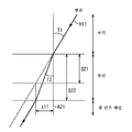
예를 들어, 도 9에 도시한 바와 같이, 소정의 광선 H11이 공기 중을 통과하여, 두께 D21의 유리재에 입사하고, 광 변조 패널(62)의 표면에 도달하였다고 하자. 또한, 광선 H11의 유리재로의 입사 위치를 통과하고, 유리재의 표면에 수직인 직선을 직선 A21이라고 하자.For example, as shown in FIG. 9, it is assumed that the predetermined light beam H11 passes through the air, enters the glass material having a thickness D21, and reaches the surface of the
이때, 공기 중을 전파하는 광선 H11의 유리재로의 입사 각도 T1에 대하여, 광선 H11의 유리재로의 입사 후의 광로와, 직선 A21의 이루는 각도 T2는, 광선 H11이 공기 중에서 유리재로 진행할 때의 상대 굴절률 k11과 입사 각도 T1로 구해진다. 즉, 각도 T2=asin(sin(T1/k11))이다.At this time, with respect to the incident angle T1 of the light beam H11 propagating in the air, the light path after the light beam H11 enters the glass material and the angle T2 of the straight line A21 are used when the light beam H11 proceeds to the glass material in the air. Is obtained by the relative refractive index k11 and the incident angle T1. That is, the angle T2 = asin (sin (T1 / k11)).
또한, 각도 T2가 구해지면, 유리재의 외관 두께 D22와 각도 T2에 의해, 직선 A21로부터, 광선 H11의 광 변조 패널(62)의 표면에의 입사 위치까지의 거리 x11이 구해진다. 즉, 거리 x11=D22×tan(T2)이다.Moreover, when angle T2 is calculated | required, the distance x11 from the straight line A21 to the incident position to the surface of the
이와 같이 하여 거리 x11을 구함으로써, 각 블록 영역에 대하여, 유저에 의해 시인되는 화소 위의 정확한 위치(이하, '화소의 시인 위치'라고도 함)를 구할 수 있다.By thus obtaining the distance x11, it is possible to obtain the exact position (hereinafter, also referred to as the 'view position of the pixel') on the pixel visually recognized by the user for each block area.
구체적으로는, 예를 들어 도 10에 도시한 바와 같이, 도면 중 가로 방향, 즉 광 변조 패널(62)의 표시면과 평행한 방향을 x 방향이라 하고, 도면 중, 세로 방향, 즉 광 변조 패널(62)의 표시면과 수직인 방향을 y 방향이라 하여, xy 좌표계 위의 소정 위치가 유저의 눈의 위치 CP라고 하자.Specifically, for example, as shown in FIG. 10, the horizontal direction in the drawing, that is, the direction parallel to the display surface of the
또한, 배리어 소자(63)의 중앙에 있는 개구부(81)를 0번째의 개구부(81)라 하고, 그 개구부(81)로부터 도면 중, 좌측 방향으로 n번째에 있는 개구부(81)를 n번째의 개구부(81)라 하고, 0번째의 개구부(81)로부터 도면 중, 우측 방향으로 n번째에 있는 개구부(81)를 -n번째의 개구부(81)라 한다.In addition, the opening
여기서, n번째의 개구부(81: 이하, '번호 n의 개구부(81)'라고도 함)에 대하여, 그 개구부(81)로부터 유저에 의해 블록 영역 내의 어느 채널 화소가 시인되는지 구하는 것을 고려한다. 우선, 위치 CP의 좌표와, 개구부(81)의 중심 위치의 좌표로부터, 위치 CP로부터의 광선의 n번째의 개구부(81)에의 입사 각도 T11이 구해진다. 즉, 입사 각도 T11은, y 방향에 평행한 직선 L21과, 위치 CP로부터의 광선과 이루는 각도이다.Here, for the n-th opening portion 81 (hereinafter also referred to as 'opening
입사 각도 T11이 구해지면, 위치 CP로부터 개구부(81)에 입사하고, 광 변조 패널(62)로 진행하는 광선, 즉 그 광선의 광로를 나타내는 직선 L22와, 직선 L21의 이루는 각도 T12가 구해진다. 즉, 도 9를 참조하여 설명한 바와 같이, 입사 각도 T11과, 개구부(81)로부터 광 변조 패널(62)의 화소까지 사이의 유리재의 굴절률 k11로부터, 각도 T12=asin(sin(T11/k11))이 구해진다.When the incidence angle T11 is obtained, a light ray entering the
그렇게 하면, 직선 L22를 나타내는 식(예를 들어, y=ax+b)이 구해지므로, 광선의 광로를 나타내는 직선 L22가 광 변조 패널(62)의 화소와 교차하는 점의 좌표를 구하면, 어느 채널 화소의 어느 위치가 유저에 의해 시인되는지를 구할 수 있다. 도 10에서는, 위치 CP로부터의 광선은, 화소 G31에 도달하고 있으며, 이 화소 G31이 유저에 의해 시인되는 것을 알 수 있다.Then, an equation representing the straight line L22 (for example, y = ax + b) is obtained. Therefore, when a coordinate of the point where the straight line L22 representing the optical path of the light beam intersects the pixel of the
또한, 유저에 의해 시인되는 화소 내의 위치, 즉 화소에 있어서의 유저의 시인 위치는, 화소의 중심 위치가 0으로 되어, -0.5 내지 0.5까지 사이의 값으로 된다. 예를 들어, 화소의 도면 중, 우측 단부의 위치가 -0.5로 되고, 화소의 도면 중, 좌측 단부의 위치가 0.5로 된다.In addition, the position in the pixel visually recognized by the user, that is, the position of the visual recognition of the user in the pixel, becomes the value between -0.5 and 0.5, with the center position of the pixel being zero. For example, the position of the right end part is -0.5 in the figure of a pixel, and the position of the left end part is 0.5 in the figure of a pixel.
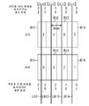
이와 같이 하여, 유저의 우안과 좌안에 대하여, 블록 영역(개구부(81))마다 유저에 의해 시인되는 화소(이하, '시인 화소'라고도 함)의 채널 m과, 그 시인 화소 위의 시인 위치를 구하면, 예를 들어 도 11의 우측에 도시한 결과가 얻어진다.In this manner, the channel m of the pixel (hereinafter, also referred to as the "viewing pixel") visually recognized by the user for each block area (opening portion 81) with respect to the right eye and the left eye of the user, and the position of the viewing position on the viewing pixel In this case, for example, the result shown on the right side of FIG. 11 is obtained.
또한, 도 11의 우측에 있어서, 횡축은 개구부(81)의 번호 n을 나타내고 있으며, 종축은 시인 화소의 채널 번호 또는 시인 위치를 나타내고 있다.In addition, in the right side of FIG. 11, the horizontal axis has shown the number n of the
도 11에서는, 꺾은선 C11은, 유저의 우안으로 보이는 각 블록 영역의 시인 화소의 채널 번호를 나타내고 있으며, 꺾은선 C12는, 유저의 우안으로 보이는 각 블록 영역의 시인 화소에 있어서의 시인 위치를 나타내고 있다.In FIG. 11, the broken line C11 shows the channel number of the visual recognition pixel of each block area seen by the user's right eye, and the broken line C12 shows the visual recognition position in the visual recognition pixel of each block area seen by the user's right eye. have.
여기서 0번째의 개구부(81)로부터, n번째(단, 1≤n)의 개구부(81)를 향하는 방향을 +x 방향이라 하고, +x 방향과 반대 방향을 -x 방향이라고 하자. 이 경우, 예를 들어 0번째의 개구부(81)에 대하여, +x 방향측에 인접하는 몇 개의 개구부(81)를 관찰하는 유저의 우안에는, 그들 개구부(81)를 통하여 채널 CH1 화소가 시인됨을 알 수 있다. 또한, 채널 CH1 화소가 시인되는 연속하여 배열하는 개구부(81)의 거의 중앙에 있는 개구부(81)에서는, 그 개구부(81)를 통하여, 채널 CH1 화소의 거의 중앙이, 유저의 우안으로 관찰되고 있음을 알 수 있다.Here, let the direction from the
이와 같은 꺾은선 C11로부터, 화살표 Q21로 나타낸 바와 같이, 광 변조 패널(62)의 표시면 위의 각 영역에서, 유저의 우안에 의해 어느 채널 화소가 관찰될지를 알 수 있다. 또한, 화살표 Q21로 나타내는 가로로 긴 사각형은, 유저로부터 보이는 광 변조 패널(62)의 표시면 전체를 나타내고 있으며, 그 사각형 안의 세로로 긴 직사각형 안의 숫자는, 그 직사각형의 영역을 관찰하는 유저의 우안에 의해 시인되는 화소의 채널 번호를 나타내고 있다.From such a broken line C11, as shown by arrow Q21, it is possible to know which channel pixel is observed by the user's right eye in each area on the display surface of the
따라서, 광 변조 패널(62)의 표시면의 도면 중, 우측 단부의 영역, 즉 +x 방향측의 단부 영역에서는, 유저의 우안에는 채널 CH2 화소가 관찰되고, 그 영역에 대하여 도면 중, 좌측에 인접하는 영역에서는, 유저의 우안에는 채널 CH1 화소가 관찰된다. 또한, 광 변조 패널(62)의 표시면의 중앙으로부터 약간 -x 방향측에 위치하는 영역에서는, 유저의 우안에는 채널 CH0 화소가 관찰되고, 그 영역의 좌측에 인접하는 영역에서는, 유저의 우안에는 채널 CH3 화소가 관찰된다.Therefore, in the area of the right end of the display surface of the
또한, 꺾은선 C12로부터, 유저의 우안 위치에서 본 각 시인 화소의 시인 위치를 알 수 있으므로, 시인 위치가 0으로 되는 블록 영역(개구부(81))의 위치를 연속 블록 영역의 경계 위치라고 하면, 화살표 Q21로 나타낸 바와 같이 경계 위치 LB51 내지 경계 위치 LB54가 정해진다.In addition, since the visual recognition position of each visual recognition pixel seen from the right eye position of a user can be known from the broken line C12, when the position of the block area | region (opening part 81) where the visual recognition position becomes 0 is made into the boundary position of a continuous block area | region, As indicated by the arrow Q21, the boundary position LB51 to the boundary position LB54 are determined.
경계 위치 LB51 내지 경계 위치 LB54에 의해 분할되어 얻어지는 각 연속 블록 영역에서는, 그 연속 블록 영역 내에서 시인 화소로 되는 2개의 채널 화소에, 우안용 시차 화상이 할당된다.In each continuous block region obtained by dividing by the boundary positions LB51 to LB54, the right eye parallax image is allocated to two channel pixels serving as the visible pixels in the continuous block region.
즉, 예를 들어 광 변조 패널(62)의 -x 방향측의 단부로부터 경계 위치 LB51까지의 사이에 있는 각 블록 영역에서는, 채널 CH2와 채널 CH3 화소에, 우안용 시차 화상이 할당된다. 또한, 경계 위치 LB51로부터 경계 위치 LB52까지의 사이에서는, 채널 CH0과 채널 CH3 화소에 우안용 시차 화상이 할당되고, 경계 위치 LB52로부터 경계 위치 LB53까지의 사이에서는, 채널 CH0과 채널 CH1 화소에 우안용 시차 화상이 할당된다.That is, in each block area between the edge part of the side of -x direction of the
또한, 경계 위치 LB53으로부터 경계 위치 LB54까지의 사이에서는, 채널 CH1과 채널 CH2 화소에 우안용 시차 화상이 할당되고, 경계 위치 LB54로부터 광 변조 패널(62)의 +x 방향측의 단부까지의 사이에서는, 채널 CH2와 채널 CH3 화소에 우안용 시차 화상이 할당된다.In addition, between the boundary position LB53 and the boundary position LB54, the parallax image for the right eye is assigned to the channel CH1 and the channel CH2 pixels, and from the boundary position LB54 to the edge part of the + x direction side of the
우안에 있어서의 경우와 마찬가지로, 도 11에 있어서, 꺾은선 C13은, 유저의 좌안으로 보이는 각 블록 영역의 시인 화소의 채널 번호를 나타내고 있으며, 꺾은선 C14는, 유저의 좌안으로 보이는 각 블록 영역의 시인 화소에 있어서의 시인 위치를 나타내고 있다. 예를 들어, 0번째의 개구부(81)에 대하여 +x 방향측에 인접하는 몇 개의 개구부(81)를 관찰하는 유저의 좌안에는, 그들 개구부(81)를 통하여 채널 CH3 화소가 시인되는 것을 알 수 있다.As in the case of the right eye, in Fig. 11, the broken line C13 indicates the channel number of the visual pixel of each block area seen by the left eye of the user, and the broken line C14 shows the block number of each block area seen by the left eye of the user. The viewing position in the viewing pixel is shown. For example, it can be seen that the channel CH3 pixel is visually recognized through the
이와 같은 꺾은선 C13으로부터, 화살표 Q22로 나타낸 바와 같이, 광 변조 패널(62)의 표시면 위의 각 영역에서, 유저의 좌안에 의해 어느 채널 화소가 관찰될지를 알 수 있다. 또한, 화살표 Q22로 나타내는 가로로 긴 사각형은, 광 변조 패널(62)의 표시면 전체를 나타내고 있으며, 그 사각형 안의 세로로 긴 직사각형 안의 숫자는, 그 직사각형 영역을 관찰하는 유저의 좌안에 의해 시인되는 화소의 채널 번호를 나타내고 있다.From such a broken line C13, as shown by arrow Q22, it is possible to know which channel pixel is observed by the left eye of the user in each area on the display surface of the
따라서, 광 변조 패널(62)의 표시면의 도면 중, 우측 단부의 영역으로부터 좌측 단부의 영역까지 순서대로, 유저의 좌안에 의해, 채널 CH0, 채널 CH3, 채널 CH2, 및 채널 CH1 화소가 관찰되는 영역이 배열되어 있는 것을 알 수 있다.Therefore, in the drawing of the display surface of the
또한, 꺾은선 C14로부터, 유저의 좌안 위치에서 본 각 시인 화소의 시인 위치를 알 수 있으므로, 시인 위치가 0으로 되는 블록 영역(개구부(81))의 위치를 연속 블록 영역의 경계 위치라고 하면, 화살표 Q22로 나타낸 바와 같이 경계 위치 LB61 내지 경계 위치 LB64가 정해진다.In addition, since the visual recognition position of each visual recognition pixel seen from the left eye position of a user can be known from the broken line C14, suppose the position of the block area | region (opening part 81) which becomes the visual recognition position is 0 as a boundary position of a continuous block area | region, As indicated by the arrow Q22, the boundary position LB61 to the boundary position LB64 are determined.
경계 위치 LB61 내지 경계 위치 LB64에 의해 분할되어 얻어지는 각 연속 블록 영역에서는, 그 연속 블록 영역 내에서 시인 화소로 되는 2개의 채널 화소에, 좌안용 시차 화상이 할당된다.In each continuous block area obtained by dividing by the boundary positions LB61 to LB64, the left eye parallax image is allocated to two channel pixels serving as the visible pixels in the continuous block region.
즉, 광 변조 패널(62)의 -x 방향측의 단부로부터 경계 위치 LB61까지의 사이에 있는 각 블록 영역에서는, 채널 CH0과 채널 CH1 화소에, 좌안용 시차 화상이 할당된다. 또한, 경계 위치 LB61로부터 경계 위치 LB62까지의 사이에서는, 채널 CH1과 채널 CH2 화소에 좌안용 시차 화상이 할당되고, 경계 위치 LB62로부터 경계 위치 LB63까지의 사이에서는, 채널 CH2와 채널 CH3 화소에 좌안용 시차 화상이 할당된다.That is, in each block area between the edge part on the side of the -x direction of the
또한, 경계 위치 LB63으로부터 경계 위치 LB64까지의 사이에서는, 채널 CH0과 채널 CH3 화소에 좌안용 시차 화상이 할당되고, 경계 위치 LB64로부터 광 변조 패널(62)의 +x 방향측의 단부까지의 사이에서는, 채널 CH0과 채널 CH1 화소에 좌안용 시차 화상이 할당된다.In addition, between the boundary position LB63 and the boundary position LB64, the left eye parallax image is allocated to the channel CH0 and the channel CH3 pixels, and from the boundary position LB64 to the edge part of the side of the + modulation direction of the
이와 같이, 각 개구부(81: 블록 영역)에 대하여, 시인 화소의 채널 번호와, 그 시인 화소에 있어서의 시인 위치가 구해지면, 연속 블록 영역의 경계 위치가 정해진다. 이에 의해, 각 연속 블록 영역에 속하는 블록 영역마다, 좌우 시차 화상을 할당하는 채널이 정해진다.In this way, for each opening 81 (block region), when the channel number of the viewer pixel and the viewer position in the viewer pixel are obtained, the boundary position of the continuous block region is determined. As a result, a channel for allocating left and right parallax images is determined for each block region belonging to each continuous block region.
단, 연속 블록 영역의 경계 위치는, 우안에서 보았을 때의 경계 위치와, 좌안에서 보았을 때의 경계 위치가 동일한 위치로 되는 것이 이상적이지만, 실제로는 유저의 우안과 좌안의 위치는 다른 위치에 있으므로, 그들 경계 위치에 어긋남이 발생한다.However, the boundary position of the continuous block area is ideally the same as the boundary position when viewed from the right eye and the boundary position when viewed from the left eye, but in reality, the positions of the user's right eye and the left eye are at different positions. The deviation occurs at their boundary positions.
예를 들어, 유저의 시점 위치가 번호 0의 개구부(81)의 대략 정면에 위치하면서, 표시부(27)로부터 시점 위치까지의 거리가 적시거리 Z0의 대략 절반인 경우에도, 도 12에 도시한 바와 같이 유저의 우안과 좌안을 기준으로 한 경계 위치의 어긋남은, 중앙으로부터 이격된 위치만큼 커진다.For example, even when the user's viewpoint position is located substantially in front of the opening
또한, 도 12에 있어서, 횡축은 개구부(81)의 번호 n을 나타내고 있으며, 종축은 시인 화소의 채널 번호 또는 시인 위치를 나타내고 있다.12, the horizontal axis has shown the number n of the
도 12에서는, 꺾은선 C21은, 유저의 우안으로 보이는 각 블록 영역의 시인 화소의 채널 번호를 나타내고 있으며, 꺾은선 C22는, 유저의 우안으로 보이는 각 블록 영역의 시인 화소에 있어서의 시인 위치를 나타내고 있다. 또한, 직선 LB71 내지 직선 LB74는, 각각 꺾은선 C22로부터 정해지는 연속 블록 영역의 경계 위치를 나타내고 있다.In FIG. 12, the line C21 shows the channel number of the visual recognition pixel of each block area seen by the user's right eye, and the line C22 shows the visual recognition position in the visual recognition pixel of each block area seen by the user's right eye. have. Moreover, the straight line LB71-the straight line LB74 have shown the boundary position of the continuous block area | region determined from the broken line C22, respectively.
또한, 꺾은선 C23은, 유저의 좌안으로 보이는 각 블록 영역의 시인 화소의 채널 번호를 나타내고 있으며, 꺾은선 C24는, 유저의 좌안으로 보이는 각 블록 영역의 시인 화소에 있어서의 시인 위치를 나타내고 있다. 또한, 직선 LB81 내지 직선 LB84는, 각각 꺾은선 C24로부터 정해지는 연속 블록 영역의 경계 위치를 나타내고 있다.Moreover, the broken line C23 has shown the channel number of the visual pixel of each block area seen by the left eye of a user, and the broken line C24 has shown the visual recognition position in the visual pixel of each block area seen by the left eye of a user. Moreover, the straight line LB81-the straight line LB84 have shown the boundary position of the continuous block area | region determined from the broken line C24, respectively.
또한, 이하, 직선 LB71 내지 직선 LB74를 경계 위치 LB71 내지 경계 위치 LB74라고도 하고, 직선 LB81 내지 직선 LB84를 경계 위치 LB81 내지 경계 위치 LB84라고도 한다.In addition, the straight line LB71 thru | or the straight line LB74 are also called boundary position LB71 thru | or the boundary position LB74 hereafter, and the straight line LB81 thru | or straight line LB84 is also called boundary position LB81 thru | or boundary position LB84.
도 12의 예에서는, 좌안을 기준으로 한 경계 위치 LB81 내지 경계 위치 LB84 각각이, 우안을 기준으로 한 경계 위치 LB71 내지 경계 위치 LB74에 대응하지만, 그들 경계 위치의 어긋남은, 광 변조 패널(62)의 중앙에서 먼 위치에 있는 경계 위치만큼 크다.In the example of FIG. 12, each of the boundary positions LB81 to LB84 relative to the left eye corresponds to the boundary positions LB71 to LB74 based on the right eye, but the deviation of these boundary positions is the
이와 같은 어긋남이 발생하면, 블록 영역에서의 각 채널 화소에의 시차 화상의 할당에 모순이 발생해버린다.When such a deviation occurs, a contradiction occurs in the assignment of the parallax image to each channel pixel in the block area.
예를 들어, 우안을 기준으로 하여, 경계 위치 LB71로부터 경계 위치 LB72까지의 사이의 블록 영역에서, 채널 CH0과 채널 CH3 화소에 우안용 시차 화상을 할당한다고 하자. 또한, 좌안을 기준으로 하여, 광 변조 패널(62)의 -x 방향측의 단부로부터 경계 위치 LB81까지의 사이의 블록 영역에서, 채널 CH0과 채널 CH1 화소에 좌안용 시차 화상을 할당한다고 하자.For example, suppose that the right eye parallax image is allocated to the channel CH0 and the channel CH3 pixels in the block area between the boundary position LB71 and the boundary position LB72 on the basis of the right eye. Further, suppose that the left eye parallax image is allocated to the channel CH0 and the channel CH1 pixels in the block region between the end of the side of the
그렇게 하면, 경계 위치 LB71로부터 경계 위치 LB81까지의 사이의 블록 영역에서는, 채널 CH0 화소에 대하여 우안용 시차 화상과 좌안용 시차 화상의 양쪽이 할당되게 되어버린다.As a result, in the block area between the boundary position LB71 and the boundary position LB81, both the right eye parallax image and the left eye parallax image are allocated to the channel CH0 pixel.
따라서, 표시 장치(11)에서는, 경계 위치 LB71 내지 경계 위치 LB74의 각각과, 경계 위치 LB81 내지 경계 위치 LB84의 각각의 중간 위치(평균 위치)를 최종적인 경계 위치인 경계 위치 LB91 내지 경계 위치 LB94라 한다.Accordingly, in the
이에 의해, 예를 들어 도면 중, 하측에 도시한 바와 같이, 경계 위치 LB91 내지 경계 위치 LB94로 분할되는 영역을 연속 블록 영역으로 하여, 각 블록 영역에서 시차 화상의 할당이 행해진다. 또한, 도면 중, 하측에는, 각 영역에서 우안용 및 좌안용 시차 화상이 할당되는 화소의 채널 번호가 기재되어 있다.As a result, for example, as shown in the lower part of the figure, parallax images are assigned in each block region, with the region divided into the boundary positions LB91 to LB94 as the continuous block region. In addition, in the lower part, the channel number of the pixel to which the right-eye and left-eye parallax image is allocated in each area | region is described.
예를 들어, 경계 위치 LB91로부터 경계 위치 LB92까지의 사이에서는, 블록 영역 내의 채널 CH0과 채널 CH3 화소에 우안용 시차 화상이 할당되고, 채널 CH1과 채널 CH2 화소에 좌안용 시차 화상이 할당된다.For example, between the boundary position LB91 and the boundary position LB92, the right eye parallax image is allocated to the channel CH0 and channel CH3 pixels in a block area, and the left eye parallax image is allocated to the channel CH1 and channel CH2 pixels.
또한, 경계 위치 LB92로부터 경계 위치 LB93의 사이에서는, 블록 영역 내의 채널 CH0과 채널 CH1 화소에 우안용 시차 화상이 할당되고, 채널 CH2와 채널 CH3 화소에 좌안용 시차 화상이 할당된다.In addition, between the boundary position LB92 and the boundary position LB93, the right eye parallax image is allocated to the channel CH0 and channel CH1 pixels in a block area, and the left eye parallax image is allocated to the channel CH2 and channel CH3 pixels.
또한, 우안을 기준으로 하는 경계 위치와 좌안을 기준으로 하는 경계 위치의 중간 위치를, 최종적인 연속 블록 영역의 경계 위치라고 하면, 경계 위치 근방에서는 우안 또는 좌안을 기준으로 한 시차 화상의 할당과 다소의 어긋남이 발생하지만, 특히 시차 화상의 입체시에 영향은 발생하지 않는다.In addition, if the intermediate position between the boundary position based on the right eye and the boundary position based on the left eye is called the boundary position of the final continuous block area, the allocation of the parallax image based on the right eye or the left eye is somewhat different in the vicinity of the boundary position. Misalignment occurs, but the influence of stereoscopic image in particular does not occur.
단, 유저의 시점 위치가, 반 시거리 표시 방식에 있어서의 최적의 시거리인 Z0/2로부터 어긋나게 되면, 즉 예를 들어 유저의 시점 위치가 표시부(27)에 접근하거나, 멀어지거나 하면, 점차 우안을 기준으로 하는 경계 위치와 좌안을 기준으로 하는 경계 위치의 어긋남이 커진다.However, when the user's viewpoint position is shifted from Z0 / 2, which is the optimal viewing distance in the half viewing distance display system, that is, when the user's viewpoint position approaches or moves away from the
그렇게 하면, 예를 들어 도 13에 도시한 바와 같이, 몇 개의 블록 영역에 있어서, 유저의 우안과 좌안에서 동일한 채널 화소가 시인 화소로서 관찰되어버린다. 또한, 도 13에 있어서, 횡축은 개구부(81)의 번호 n을 나타내고 있으며, 종축은 시인 화소의 채널 번호 또는 시인 위치를 나타내고 있다.Then, as shown, for example in FIG. 13, the same channel pixel is observed as a viewing pixel in the right eye and left eye of a user in some block area | regions. In addition, in FIG. 13, the horizontal axis has shown the number n of the
도 13에서는, 꺾은선 C31은, 유저의 우안으로 보이는 각 블록 영역의 시인 화소의 채널 번호를 나타내고 있으며, 꺾은선 C32는, 유저의 우안으로 보이는 각 블록 영역의 시인 화소에 있어서의 시인 위치를 나타내고 있다. 또한, 꺾은선 C33은, 유저의 좌안으로 보이는 각 블록 영역의 시인 화소의 채널 번호를 나타내고 있으며, 꺾은선 C34는, 유저의 좌안으로 보이는 각 블록 영역의 시인 화소에 있어서의 시인 위치를 나타내고 있다.In FIG. 13, the broken line C31 shows the channel number of the visual recognition pixel of each block area seen by the user's right eye, and the broken line C32 shows the visual recognition position in the visual recognition pixel of each block area seen by the user's right eye. have. Moreover, the broken line C33 has shown the channel number of the visual pixel of each block area seen by the left eye of a user, and the broken line C34 has shown the visual recognition position in the visual pixel of each block area seen by the left eye of a user.
이 예에서는, 꺾은선 C31과 꺾은선 C33의 일부가 겹쳐 있으며, 이들 부분에서는 블록 영역에 있어서, 유저의 우안과 좌안에서 동일한 채널 화소가 시인 화소로서 관찰된다. 그로 인해, 우안을 기준으로 하여 구한 경계 위치와, 좌안을 기준으로 하여 구한 경계 위치의 중간 위치를 최종적인 연속 블록 영역의 경계 위치로 하여도, 소정의 블록 영역에서는, 동일한 채널에 우안용과 좌안용 양쪽의 시차 화상을 할당하지 않으면 안 된다. 즉, 유저가 피사체를 입체적으로 관찰할 수 없게 되어, 우안용 시차 화상과 좌안용 시차 화상을 이용한 입체 표시가 불가능해진다.In this example, part of the broken line C31 and a part of the broken line C33 overlap, and in these parts, the same channel pixel is observed as the visual pixel in the right eye and the left eye of the user in the block area. Therefore, even if the boundary position obtained on the basis of the right eye and the intermediate position of the boundary position obtained on the basis of the left eye are the boundary positions of the final continuous block area, the right channel and the left eye are used for the same channel in the predetermined block area. Both parallax images must be allocated. That is, the user cannot observe the subject three-dimensionally, and three-dimensional display using the right-eye parallax image and the left-eye parallax image becomes impossible.
이와 같이, 소정의 시점 위치에 있어서, 개구부(81: 블록 영역)마다, 블록 영역 내의 시인 화소를 구하면, 그 결과로부터, 유저가 현 시점 위치에서 표시부(27)를 관찰하는 경우에, 시차 화상의 입체시가 가능한지 특정할 수 있다.As described above, when the visual recognition pixel in the block region is obtained for each opening 81 (block region) at a predetermined viewpoint position, from the result, when the user observes the
따라서, 각 시점 위치에 대하여, 블록 영역마다 시인 화소를 구하는 연산을 행하면, 예를 들어 도 14에 도시한 바와 같이, xy 평면 위에 있어서 입체 표시(입체시)가 가능한 영역과 불가능한 영역을 구할 수 있다. 또한, 도 14에 있어서, 가로 방향 및 세로 방향은 x 방향 및 y 방향을 나타내고 있다.Therefore, when a view pixel is calculated for each block region for each viewpoint position, for example, as shown in FIG. 14, a region capable of stereoscopic display (when stereoscopic) and an impossible region on the xy plane can be obtained. . In addition, in FIG. 14, the horizontal direction and the vertical direction have shown the x direction and the y direction.
도 14의 예에서는, 표시부(27)의 주위 영역 중, 사선이 그어진 영역 WR11은, 시차 화상의 입체 표시가 가능한 영역을 나타내고 있다. 따라서, 표시 장치(11)는 반 시거리 표시 방식에 의해 시차 화상의 입체 표시를 행하는 경우에 있어서, 영역 WR11 안에 있는 영역 WR12를 시차 화상의 입체 표시가 가능한 영역이라 한다. 그리고, 표시 장치(11)는 유저의 시점 위치가 영역 WR12 안에 있는 경우, 좌우 시차 화상에 기초하여 피사체를 입체 표시시키고, 유저의 시점 위치가 영역 WR12 밖에 있는 경우, 좌우 중 어느 한쪽의 시차 화상을 표시한다.In the example of FIG. 14, the area WR11 in which the diagonal lines are drawn out of the peripheral area of the
이와 같이 유저의 시점 위치에 따라서, 3D 표시와 2D 표시를 전환함으로써, 유저에게 위화감이 없는 자연스러운 화상을 제시할 수 있다.In this way, by switching the 3D display and the 2D display in accordance with the position of the user's viewpoint, a natural image without discomfort can be presented to the user.
[표시 처리의 설명][Description of Display Processing]
다음으로, 표시 장치(11)의 구체적인 동작에 대하여 설명한다.Next, a specific operation of the
표시 장치(11)는 우안용 시차 화상과 좌안용 시차 화상을 포함하여 이루어지는 입체 화상이 지정되고, 이들 시차 화상의 반 시거리 표시 방식에 의한 표시가 지시되면, 표시 처리를 행하여, 시차 화상을 입체 표시시킨다. 이하, 도 15의 흐름도를 참조하여, 표시 장치(11)에 의한 표시 처리에 대하여 설명한다.The
스텝 S11에 있어서, 촬상부(21)는 표시부(27)의 주위 영역의 화상을 주변 화상으로서 촬상하고, 검출부(22)에 공급한다.In step S11, the
스텝 S12에 있어서, 검출부(22)는 촬상부(21)로부터 공급된 주변 화상에 기초하여, 유저의 눈을 검출한다. 예를 들어 검출부(22)는 주변 화상으로부터 유저의 얼굴을 검출하고, 검출된 얼굴의 영역으로부터, 또한 유저의 눈을 검출한다.In step S12, the
스텝 S13에 있어서, 검출부(22)는 주변 화상으로부터 유저의 눈이 검출되었는지 여부를 판정한다.In step S13, the
스텝 S13에 있어서, 유저의 눈이 검출되었다고 판정된 경우, 스텝 S14에 있어서, 시점 위치 산출부(31)는 검출된 유저의 눈의 위치로부터, 유저의 시점 위치를 산출하고, 할당 제어부(23)에 공급한다. 예를 들어 시점 위치 산출부(31)는 xy 평면 위에 있어서의 유저의 좌우 눈의 중간 위치를, 시점 위치로서 구한다.When it is determined in step S13 that the eyes of the user are detected, in step S14, the viewpoint
스텝 S15에 있어서, 할당 제어부(23)의 판정부(32)는 시점 위치 산출부(31)로부터 공급된 유저의 시점 위치에 기초하여, 시차 화상의 입체 표시가 가능한지 여부를 판정한다.In step S15, the
예를 들어 판정부(32)는 도 14에 도시한 입체 표시 가능한 영역 WR12를 특정하기 위한 영역 정보를 미리 기록하고 있으며, 기록하고 있는 영역 정보에 기초하여, 유저의 시점 위치가 영역 WR12 안의 위치인지 여부를 특정함으로써, 입체 표시가 가능할지를 판정한다. 따라서, 예를 들어 유저의 시점 위치가 영역 WR12 안의 위치인 경우, 입체 표시가 가능하다고 판정된다.For example, the
스텝 S15에 있어서, 입체 표시가 가능하다고 판정된 경우, 스텝 S16에 있어서, 시인 위치 산출부(33)는 시점 위치 산출부(31)로부터 공급된 유저의 시점 위치에 기초하여, 개구부(81)마다 시인 화소 및 시인 위치를 산출한다.When it is determined in step S15 that stereoscopic display is possible, in step S16, the visual recognition
즉, 시인 위치 산출부(33)는 시점 위치로부터 정해지는 유저의 우안 위치와 좌안 위치에 대하여, 도 10을 참조하여 설명한 연산을 행하여, 개구부(81: 블록 영역)마다, 그 개구부(81)를 통하여 관찰되는 시인 화소와, 그 시인 화소에 있어서의 시인 위치를 산출한다. 이에 의해, 예를 들어 도 11에 도시한 연산 결과가 얻어진다. 즉, 각 블록 영역에 대하여, 유저의 우안 또는 좌안에서 관찰되는 화소(시인 화소)의 채널 번호와, 그 화소 위의 유저에 의해 관찰되는 위치(시인 위치)가 구해진다.That is, the visual recognition
스텝 S17에 있어서, 경계 위치 산출부(34)는 각 블록 영역에 대한 시인 위치의 산출 결과에 기초하여, 연속 블록 영역의 경계 위치를 산출한다.In step S17, the boundary
구체적으로는 경계 위치 산출부(34)는 우안 위치에 대하여 구해진 각 블록 영역의 시인 위치의 산출 결과에 기초하여, 시인 위치가 「0」이 되는 위치를, 우안을 기준으로 하는 경계 위치라고 한다. 즉, 개구부(81)를 통하여, 우안에 의해 화소의 중앙이 관찰되는 블록 영역의 위치가, 우안을 기준으로 하는 경계 위치로 된다. 마찬가지로, 경계 위치 산출부(34)는 좌안 위치에 대하여 구해진 각 블록 영역의 시인 위치의 산출 결과에 기초하여, 시인 위치가 「0」으로 되는 위치를, 좌안을 기준으로 하는 경계 위치라고 한다.Specifically, the boundary
그리고, 경계 위치 산출부(34)는 우안을 기준으로 하는 경계 위치와, 그들 경계 위치에 대응하는, 좌안을 기준으로 하는 경계 위치의 중간 위치를, 최종적인 연속 블록 영역의 경계 위치라고 한다. 여기서, 우안을 기준으로 하는 경계 위치에 대응하는, 좌안을 기준으로 하는 경계 위치란, 우안을 기준으로 하는 경계 위치에 가장 가까운 위치에 있는, 좌안을 기준으로 하는 경계 위치이다.The
이와 같은 연산에 의해, 예를 들어 도 12에 도시한 경계 위치 LB91 내지 경계 위치 LB94가 구해진다.By such calculation, the boundary position LB91 thru | or the boundary position LB94 shown, for example in FIG. 12 are calculated | required.
스텝 S18에 있어서, 경계 위치 산출부(34)는 연속 블록 영역의 경계 위치의 산출 결과에 기초하여, 각 블록 영역의 화소에 우안용 또는 좌안용 시차 화상을 할당한다.In step S18, the boundary
도 12의 예에서는, 예를 들어 광 변조 패널(62)의 표시면 위의 블록 영역 중, 경계 위치 LB91로부터 경계 위치 LB92의 사이에 있는 블록 영역에서는, 채널 CH0과 채널 CH3 화소(채널 영역)에 대하여 우안용 시차 화상이 할당된다. 또한, 경계 위치 LB91로부터 경계 위치 LB92의 사이에 있는 블록 영역에 있어서, 채널 CH1과 채널 CH2 화소에 대하여 좌안용 시차 화상이 할당된다.In the example of FIG. 12, for example, in the block region on the display surface of the
보다 구체적으로는, 예를 들어 도 16에 도시한 바와 같이, 광 변조 패널(62) 위의 4개의 화소를 포함하여 이루어지는 영역이 블록 영역 BR1 및 블록 영역 BR2로 되었다고 하자. 또한, 도 16에 있어서, 가로 방향은 x 방향을 나타내고 있다.More specifically, for example, as shown in FIG. 16, it is assumed that a region including four pixels on the
도 16에서는, 화살표 Q41 내지 화살표 Q43에 의해 나타내는 직사각형은, 우안용 시차 화상, 좌안용 시차 화상 및 광 변조 패널(62)을 나타내고 있다. 또한, 그들 직사각형 안의 1개의 사각형은 1개의 화소를 나타내고 있으며, 각 화소 내의 문자 「R」, 「G」, 「B」는, 각각 화소의 색을 나타내고 있다.In FIG. 16, the rectangles indicated by arrows Q41 to Q43 represent the right eye parallax image, the left eye parallax image, and the
예를 들어, 광 변조 패널(62) 위의 화소 G51 내지 화소 G54가 포함되는 영역이, 블록 영역 BR1로 되어 있으며, 화소 G55 내지 화소 G58이 포함되는 영역이, 블록 영역 BR2로 되어 있다. 여기서, 예를 들어 화소 G51은 R(적색)의 컬러 필터가 설치된, R의 광만을 투과시키는 화소이며, 화소 G52는 G(녹색)의 컬러 필터가 설치된, G의 광만을 투과시키는 화소이다.For example, the area in which the pixels G51 to G54 on the
또한, 광 변조 패널(62) 위의 각 화소의 도면 중, 하측에는 그들 화소의 채널 번호가 기재되어 있다. 예를 들어, 화소 G51은 채널 CH0 화소이며, 화소 G52는 채널 CH1 화소이다.In the drawing of each pixel on the
또한, 도면 중, 가로 방향에 있어서 광 변조 패널(62) 위의 각 화소와 동일한 위치에는, 그들 화소와 동일한 위치에 있는, 우안용 및 좌안용 시차 화상의 화소가 나타나 있다.Moreover, in the figure, the pixel of the right-eye and left-eye parallax image which is in the same position as those pixel on the same position as each pixel on the
일반적으로, 화상 위의 화소는, R, G, B의 각 색의 값을 가지기 때문에, 서로 인접하는 R, G, B의 영역이 1개의 화소로 되고, R, G, B의 각 색의 영역이 서브 픽셀(서브 화소)로서 다루어지는 경우가 많다.In general, since the pixels on the image have values of respective colors of R, G, and B, areas of R, G, and B adjacent to each other become one pixel, and regions of each of the colors of R, G, and B It is often treated as this subpixel (subpixel).
구체적으로는, 예를 들어 우안용 시차 화상의 도면 중, 좌측 단부가 연속하는 R, G, B의 3개의 화소를 포함하여 이루어지는 영역이 일반적으로는 1개의 화소(이하, 적절히 'RGB 화소'라고도 함)로 되고, 각 색의 화소 G61이나 화소 G62가 서브 픽셀로서 다루어지는 경우가 많다. 그러나, 여기에서는, 이들 화소 G61이나 화소 G62를 '1개의 화소'라 칭하기로 한다.Specifically, for example, in the drawing of the parallax image for the right eye, an area including three pixels of R, G, and B, which are continuous at the left end, is generally one pixel (hereinafter, also appropriately referred to as an 'RGB pixel'). The pixel G61 and the pixel G62 of each color are often treated as subpixels. However, here, these pixels G61 and G62 will be referred to as "one pixel".
마찬가지로, 예를 들어 일반적으로, 화소 G51 내지 화소 G53을 포함하여 이루어지는 3개의 색의 영역이 1개의 화소로서 다루는 경우가 있지만, 여기에서는 화소 G51 내지 화소 G53의 각각을, 1개의 화소로서 다루기로 한다.Similarly, for example, in general, three color regions including the pixels G51 to G53 may be treated as one pixel. However, each of the pixels G51 to G53 will be treated as one pixel. .
예를 들어, 블록 영역 BR1과 블록 영역 BR2에 있어서, 경계 위치 산출부(34)에 의해, 채널 CH0과 채널 CH1 화소에 우안용 시차 화상이 할당되고, 채널 CH2와 채널 CH3 화소에 좌안용 시차 화상이 할당되었다고 하자.For example, in the block area BR1 and the block area BR2, the
이때, 경계 위치 산출부(34)는 우안용 시차 화상의 화소 G61과 화소 G62를, 그들 화소와 동일한 위치에 있는 광 변조 패널(62) 위의 화소 G51과 화소 G52에 할당한다. 또한, 경계 위치 산출부(34)는 좌안용 시차 화상의 화소 G71과 화소 G72를, 그들 화소와 동일한 위치에 있는 광 변조 패널(62) 위의 화소 G53과 화소 G54에 할당한다.At this time, the
마찬가지로, 경계 위치 산출부(34)는 우안용 시차 화상의 화소 G63과 화소 G64를, 화소 G55와 화소 G56에 할당하고, 좌안용 시차 화상의 화소 G73과 화소 G74를, 화소 G57과 화소 G58에 할당한다.Similarly, the boundary
이와 같이, 블록 영역의 소정의 채널에 우안용 또는 좌안용 시차 화상이 할당되었을 때, 보다 상세하게는, 그 채널 화소에는, 그 화소와 동일한 위치에 있는 우안용 또는 좌안용 시차 화상의 화소가 할당된다.In this way, when a right eye or left eye parallax image is assigned to a predetermined channel in the block area, more specifically, the pixel of the right eye or left eye parallax image at the same position as the pixel is assigned to the channel pixel. do.
이와 같이 하여, 블록 영역마다, 각 채널 화소에 대하여 우안용 또는 좌안용 시차 화상을 할당하면, 경계 위치 산출부(34)는 그 할당 결과를 생성부(25)에 공급하고, 합성 화상의 생성을 지시한다.In this way, when the right-eye or left-eye parallax image is assigned to each channel pixel for each block region, the boundary
스텝 S19에 있어서, 생성부(25)는 경계 위치 산출부(34)로부터 공급된 할당 결과와, 기록부(24)로부터 판독한 우안용 및 좌안용 시차 화상에 기초하여, 합성 화상을 생성하고, 표시 제어부(26)에 공급한다. 예를 들어, 도 16에 도시한 할당이 행해진 경우, 생성부(25)는 우안용 시차 화상의 화소 G61과 화소 G62가, 화소 G51과 화소 G52에 표시되고, 좌안용 시차 화상의 화소 G71과 화소 G72가, 화소 G53과 화소 G54에 표시되도록, 합성 화상을 생성한다.In step S19, the
또한, 시차 화상을 기록부(24)로부터 취득하는 것이 아니라, 외부 장치로부터 시차 화상을 취득하거나, 시차 화상을 수신하도록 하여도 된다.In addition, instead of acquiring the parallax image from the
스텝 S20에 있어서, 표시 제어부(26)는 생성부(25)로부터 공급된 합성 화상을 표시부(27)에 공급하여 표시시킨다.In step S20, the
예를 들어, 표시부(27)는 공급된 합성 화상에 기초하여 백라이트(61)로부터 광을 사출시킴과 함께, 광 변조 패널(62)에 전압을 인가시켜서 백라이트(61)로부터의 광의 투과율을 화소마다 제어한다. 또한, 표시부(27)는 배리어 소자(63)에 전압을 인가시켜서 개구부(81)와 차폐부(82)를 포함하여 이루어지는 패럴랙스 배리어를 형성시킨다.For example, the
이에 의해, 백라이트(61)로부터 광 변조 패널(62)의 각 화소를 투과한 광은, 패럴랙스 배리어에 의해 광학적으로 분리되고, 분리된 일부 광이 유저의 우안 또는 좌안에 입사하여, 유저에 의해 시차 화상 위의 피사체가 입체적으로 관찰된다. 즉, 합성 화상 위의 우안용 시차 화상의 영역이 유저의 우안에 의해 관찰되고, 합성 화상 위의 좌안용 시차 화상의 영역이 유저의 좌안에 의해 관찰된다.As a result, the light transmitted through each pixel of the
이때, 예를 들어 좌우의 시차 화상에 부수되는 음성이 있는 경우에는, 표시 장치(11)는 합성 화상의 표시에 맞춰, 부수되는 음성을 스피커(도시생략)로부터 출력시킨다.At this time, for example, when there is audio accompanying the left and right parallax images, the
스텝 S21에 있어서, 표시 장치(11)는 표시 장치(11)의 전원을 오프할지 여부를 판정한다. 예를 들어, 유저의 조작에 의해 전원의 오프가 지시된 경우, 전원을 오프한다고 판정된다.In step S21, the
스텝 S21에 있어서, 전원을 오프하지 않는다고 판정된 경우, 처리는 스텝 S11로 되돌아가고, 전술한 처리가 반복된다. 즉, 유저의 시점 위치의 이동에 따라서, 블록 영역 내의 각 채널 화소에 대한 시차 화상의 할당이 변경되고, 새로운 할당에 따라서 생성된 합성 화상이 표시된다.If it is determined in step S21 that the power supply is not turned off, the process returns to step S11 and the above-described process is repeated. That is, in accordance with the movement of the viewpoint position of the user, the assignment of the parallax image to each channel pixel in the block area is changed, and the synthesized image generated according to the new assignment is displayed.
이에 반하여, 스텝 S21에 있어서, 전원을 오프한다고 판정된 경우, 표시 장치(11)는 각 부의 처리를 정지시켜 전원을 오프하고, 표시 처리는 종료된다.On the other hand, when it is determined in step S21 that the power supply is turned off, the
또한, 스텝 S15에 있어서, 입체 표시가 가능하지 않다고 판정된 경우, 할당 제어부(23)는 생성부(25)에 2차원의 시차 화상의 표시를 지시하고, 처리는 스텝 S22로 진행한다.If it is determined in step S15 that stereoscopic display is not possible, the
스텝 S22에 있어서, 생성부(25)는 할당 제어부(23)로부터의 지시에 따라서, 2차원의 시차 화상을 표시시킨다. 즉, 생성부(25)는 기록부(24)로부터 우안용 또는 좌안용 중 어느 하나의 시차 화상을 판독하여, 판독한 시차 화상을 그대로 표시 제어부(26)에 공급한다.In step S22, the
그렇게 하면, 표시 제어부(26)는 생성부(25)로부터 공급된 시차 화상을 표시부(27)에 공급하고, 시차 화상을 표시시킨다. 이때, 예를 들어 배리어 소자(63)는 패럴랙스 배리어를 형성하지 않고, 표시부(27)는 시차 화상을 그대로 표시시킨다. 또한, 표시부(27)에 설치되는 패럴랙스 배리어가 고정식의 것인 경우에서도, 표시부(27)에 시차 화상을 그대로 표시시킴으로써, 시차 화상이 2차원 표시(2D 표시)된다.Then, the
스텝 S22에 있어서 시차 화상이 표시되면, 그 후, 처리는 스텝 S21로 진행하고, 전술한 처리가 행해진다.If a parallax image is displayed in step S22, the process then proceeds to step S21 and the above-described process is performed.
또한, 스텝 S13에 있어서, 유저의 눈이 검출되지 않았다고 판정된 경우, 검출부(22)는 눈이 검출되지 않은 취지의 검출 결과를 할당 제어부(23)에 공급하고, 처리는 스텝 S23으로 진행한다.In addition, when it is determined in step S13 that the user's eyes have not been detected, the
스텝 S23에 있어서, 할당 제어부(23)는 유저의 눈이 검출되지 않은 상태로 되고 나서, 일정 시간이 경과하였는지 여부를 판정한다.In step S23, the
스텝 S23에 있어서, 일정 시간이 경과하지 않았다고 판단된 경우, 처리는 스텝 S22로 진행하고, 전술한 처리가 행해진다. 즉, 표시부(27)에 시차 화상이 2차원 표시된다.If it is determined in step S23 that the fixed time has not elapsed, the process proceeds to step S22 and the above-described process is performed. That is, the parallax image is displayed two-dimensionally on the
이에 반하여, 스텝 S23에 있어서, 일정 시간 경과하였다고 판정된 경우, 스텝 S24에 있어서, 할당 제어부(23)는 생성부(25)를 제어하여 화상이 표시되지 않는 상태로 한다. 생성부(25)는 할당 제어부(23)의 제어에 따라서, 화상의 표시 제어부(26)에의 공급을 정지한다. 이에 의해, 표시부(27)에는, 화상이 표시되지 않는 상태로 된다. 즉, 화면 끄기 상태로 된다.On the other hand, when it is determined in step S23 that the predetermined time has elapsed, in step S24, the
또한, 시차 화상에 부수되는 음성이 있는 경우, 화면 끄기 상태에서 음성만이 계속하여 재생되도록 하여도 되고, 음성도 소거되도록 하여도 된다. 이와 같이, 일정 시간, 유저의 눈이 검출되지 않은 경우, 유저는 시차 화상을 보고 있지 않을 것이므로, 화면 끄기함으로써 소비 전력을 억제할 수 있다.In addition, when there is a voice accompanying the parallax image, only the voice may be continuously reproduced in the screen off state, or the voice may also be erased. In this manner, when the user's eyes are not detected for a certain time, the user will not be viewing a parallax image, so that power consumption can be suppressed by turning off the screen.
스텝 S24에 있어서 화면 끄기 상태로 되면, 그 후, 처리는 스텝 S21로 진행하여, 전술한 처리가 행해지고 표시 처리는 종료된다.When the screen is turned off in step S24, the processing proceeds to step S21 after which the above-described processing is performed and the display processing ends.
이상과 같이 하여, 표시 장치(11)는 유저의 시점 위치에 기초하여, 블록 영역마다 시인 화소와 시인 위치를 산출하고, 그 산출 결과에 기초하여, 블록 영역의 각 채널 화소에, 우안용 또는 좌안용 시차 화상을 할당하여 합성 화상을 생성한다.As described above, the
이때, 블록 영역의 x 방향에 인접하여 배열하는 적어도 2개의 화소에, 우안용 또는 좌안용 시차 화상 중 동일한 시차 화상이 할당되도록 함으로써, 보다 간단하게 크로스토크의 발생을 억제하여, 보다 고품위의 화상을 제시할 수 있게 된다.At this time, by assigning the same parallax image among the right-eye or left-eye parallax images to at least two pixels arranged adjacent to the x-direction of the block area, the occurrence of crosstalk can be more easily suppressed, and a higher quality image can be obtained. Can present.
또한, 유저의 시점 위치의 이동에 따라서, 블록 영역 내의 각 채널 화소에 대한 시차 화상의 할당을 변화시킴으로써, 각 채널에 있어서의 시차 화상의 표시 전환을 유저가 느낄 수 없어, 보다 자연스럽고 고품위의 화상을 제시할 수 있다.In addition, by changing the allocation of the parallax image for each channel pixel in the block area in accordance with the movement of the viewpoint position of the user, the user cannot feel the display switching of the parallax image in each channel, and the image is more natural and higher quality. Can be presented.
또한, 이상에 있어서 설명한 표시 처리에서는, 판정부(32)가 입체 표시 가능한 영역을 특정하기 위한 영역 정보를 미리 기록하고 있다고 설명하였지만, 그러한 영역 정보를 미리 기록하지 않고, 시인 화소의 산출 결과로부터, 입체 표시 가능한지 판정하도록 하여도 된다.In addition, although the display process demonstrated above demonstrated that the
그와 같은 경우, 판정부(32)는 시인 위치 산출부(33)에 의해 산출된, 각 블록 영역의 시인 화소의 산출 결과를 이용한다. 즉, 판정부(32)는 우안을 기준으로 하는 시인 화소와, 좌안을 기준으로 하는 시인 화소가, 동일한 채널 화소로 되는 블록 영역이 있는 경우, 입체 표시가 가능하지 않다고 판정한다.In such a case, the
<변형예 1>≪ Modification Example 1 &
또한, 이상에 있어서는, 표시 장치(11)가 단독으로 반 시거리 표시 방식에 의한 입체 표시를 행한다고 설명하였지만, 몇 개의 장치를 포함하여 이루어지는 표시 시스템에 의해, 반 시거리 표시 방식에서의 입체 표시가 행해지도록 하여도 된다.In addition, in the above description, although the
그와 같은 경우, 표시 시스템은, 예를 들어 도 17에 도시한 바와 같이 구성된다.In such a case, the display system is configured as shown in FIG. 17, for example.
즉, 도 17의 표시 시스템은, 촬상 장치(121), 화상 처리 장치(122), 및 표시 장치(123)로 구성된다. 또한, 도 17에 있어서, 도 1에서의 경우와 대응하는 부분에는 동일한 부호를 부여하고 있으며, 그 설명은 적절히 생략한다.That is, the display system of FIG. 17 is comprised by the
촬상 장치(121)는 표시 장치(123)의 주위 화상을 주변 화상으로서 촬상하고, 화상 처리 장치(122)에 공급한다. 화상 처리 장치(122)는 촬상 장치(121)로부터의 주변 화상을 이용하여 합성 화상을 생성하고, 표시 장치(123)에 공급한다.The
화상 처리 장치(122)는 검출부(22), 할당 제어부(23), 기록부(24) 및 생성부(25)로 구성된다. 검출부(22)는 촬상 장치(121)로부터의 주변 화상으로부터 유저의 눈을 검출하여, 그 검출 결과를 할당 제어부(23)에 공급하고, 할당 제어부(23)는 검출부(22)로부터의 검출 결과에 기초하여, 블록 영역의 각 채널 화소에의 시차 화상의 할당을 행한다.The
또한, 생성부(25)는 할당 제어부(23)의 제어에 따라서 기록부(24)에 기록된 좌우 눈의 시차 화상으로부터 합성 화상을 생성하고, 표시 장치(123)에 공급한다.The
표시 장치(123)는 예를 들어 표시부(27) 및 표시 제어부(26)와 마찬가지의 기능을 갖는 입체 화상을 표시 가능한 표시 장치이며, 생성부(25)로부터 공급된 합성 화상에 기초하여, 시차 화상 위의 피사체를 입체 표시한다.The
<변형예 2>≪ Modification Example 2 &
또한, 이상에 있어서는, 표시부(27)가 4 시점의 시차 화상을 입체 표시 가능한 표시 장치인 경우를 예로서 설명하였지만, 표시부(27)는 5 이상의 복수 시점의 시차 화상을 입체 표시 가능한 표시 장치이어도 된다.In the above description, the case where the
예를 들어, 표시부(27)가 6 시점의 시차 화상을 입체 표시 가능한 경우, 도 18에 도시한 바와 같이, 6개의 서로 다른 채널 화소를 포함하여 이루어지는 영역이 블록 영역으로 되고, 그 블록 영역에 대하여 1개의 개구부(81)가 설치된다. 또한, 도 18에 있어서, 도 3에서의 경우와 대응하는 부분에는 동일한 부호를 부여하고 있으며, 그 설명은 적절히 생략한다.For example, when the
도 18의 예에서는, 6개의 서로 다른 채널 화소 G91 내지 화소 G96을 포함하는 영역이, 1개의 블록 영역으로 되어 있다.In the example of FIG. 18, an area including six different channel pixels G91 to G96 serves as one block area.
이 경우, 시차 화상을 입체시 가능한 유저의 시점 위치는, 서로 3 화소만큼 이격된 위치에 있는 화소가, 유저의 우안 및 좌안을 기준으로 한 시인 화소로 되는 위치로 된다. 도 18의 예에서는, 유저의 우안 ER에 의해 화소 G95가 시인되고 있으며, 유저의 좌안 EL에 의해 화소 G92가 시인되고 있다.In this case, the viewpoint position of the user who can stereoscopically view the parallax image becomes a position where the pixels at positions separated from each other by three pixels become the pixel of the viewer which is based on the right eye and the left eye of the user. In the example of FIG. 18, the pixel G95 is visually recognized by the right eye ER of the user, and the pixel G92 is visually recognized by the left eye EL of the user.
또한, 시차 화상의 할당 시에는, 적어도 연속하여 배열하는 3개의 채널 화소에, 우안용 또는 좌안용 중 어느 하나의 시차 화상이 할당된다. 예를 들어, 도 18에서는 화소 G91 내지 화소 G93에 좌안용 시차 화상이 할당되고, 화소 G94 내지 화소 G96에 우안용 시차 화상이 할당된다.In addition, at the time of assigning a parallax image, the parallax image of either right eye or left eye is allocated to the three channel pixels arranged at least continuously. For example, in FIG. 18, the left eye parallax image is assigned to the pixels G91 to G93, and the right eye parallax image is assigned to the pixels G94 to G96.
이와 같이, 복수 시점의 시차 화상을 입체 표시 가능한 표시부에서는, 우안과 좌안의 시인 화소가, 2 화소 이상 이격된 화소로 되도록 함으로써, 시차 방향으로 연속하여 배열하는 2 이상의 화소에 동일한 시점의 시차 화상을 할당할 수 있다. 이에 의해, 간단하게 크로스토크의 발생을 억제하여, 보다 고품질의 시차 화상을 제시할 수 있게 된다.As described above, in the display unit capable of stereoscopic display of parallax images of a plurality of viewpoints, the pixels of the right eye and the left eye are arranged to be two pixels or more separated from each other, thereby distributing the parallax images of the same viewpoint to two or more pixels continuously arranged in the parallax direction. Can be assigned. This makes it possible to easily suppress the occurrence of crosstalk and to present a higher quality parallax image.
전술한 일련의 처리는, 하드웨어에 의해 실행할 수도 있고, 소프트웨어에 의해 실행할 수도 있다. 일련의 처리를 소프트웨어에 의해 실행하는 경우에는, 그 소프트웨어를 구성하는 프로그램이, 전용의 하드웨어에 내장되어 있는 컴퓨터, 또는 각종 프로그램을 인스톨함으로써, 각종 기능을 실행하는 것이 가능한, 예를 들어 범용의 퍼스널 컴퓨터 등에, 프로그램 기록 매체로 인스톨된다.The series of processes described above may be executed by hardware or by software. When a series of processes are performed by software, the program which comprises the software can perform various functions by installing the computer or various programs which were built in exclusive hardware, for example, a general purpose personal It is installed in a computer or the like on a program recording medium.
도 19는, 전술한 일련의 처리를 프로그램에 의해 실행하는 컴퓨터 하드웨어의 구성예를 나타내는 블록도이다.19 is a block diagram showing an example of the configuration of computer hardware for executing the above-described series of processes by a program.
컴퓨터에 있어서, CPU(201: Central Processing Unit), ROM(202: Read Only Memory), RAM(203: Random Access Memory)은, 버스(204)에 의해 서로 접속되어 있다.A central processing unit (CPU) 201, a read only memory (ROM) 202 and a random access memory (RAM) 203 are connected to each other by a
버스(204)에는 또한, 입출력 인터페이스(205)가 접속되어 있다. 입출력 인터페이스(205)에는, 키보드, 마우스, 마이크로폰 등을 포함하는 입력부(206), 디스플레이, 스피커 등을 포함하는 출력부(207), 하드디스크나 불휘발성 메모리 등을 포함하는 기록부(208), 네트워크 인터페이스 등을 포함하는 통신부(209), 자기디스크, 광디스크, 광자기디스크, 또는 반도체 메모리 등의 리무버블 미디어(211)를 구동하는 드라이브(210)가 접속되어 있다.An input /
이상과 같이 구성되는 컴퓨터에서는, CPU(201)가, 예를 들어 기록부(208)에 기록되어 있는 프로그램을, 입출력 인터페이스(205) 및 버스(204)를 통하여, RAM(203)에 로드하여 실행함으로써, 전술한 일련의 처리가 행해진다.In the computer configured as described above, the
컴퓨터(CPU(201))가 실행하는 프로그램은, 예를 들어 자기디스크(플렉시블디스크를 포함함), 광디스크(CD-ROM(Compact Disc-Read Only Memory), DVD(Digital Versatile Disc) 등), 광자기 디스크, 또는 반도체 메모리 등을 포함하는 패키지 미디어인 리무버블 미디어(211)에 기록하거나, 또는 근거리 네트워크, 인터넷, 디지털 위성 방송과 같은 유선 또는 무선의 전송 매체를 통하여 제공된다.The program executed by the computer (CPU 201) may be, for example, a magnetic disk (including a flexible disk), an optical disk (CD-ROM (Compact Disc-Read Only Memory), DVD (Digital Versatile Disc, etc.), optical It is recorded on the
그리고, 프로그램은, 리무버블 미디어(211)를 드라이브(210)에 장착함으로써, 입출력 인터페이스(205)를 통하여, 기록부(208)에 인스톨할 수 있다. 또한, 프로그램은, 유선 또는 무선의 전송 매체를 통하여, 통신부(209)에서 수신하고, 기록부(208)에 인스톨할 수 있다. 그 밖에, 프로그램은, ROM(202)이나 기록부(208)에, 미리 인스톨해 둘 수 있다.The program can be installed in the
또한, 컴퓨터가 실행하는 프로그램은, 본 명세서에서 설명하는 순서를 따라서 시계열로 처리가 행해지는 프로그램이어도 되고, 병렬로, 또는 호출이 행해졌을 때 등의 필요한 타이밍에 처리가 행해지는 프로그램이어도 된다.The program executed by the computer may be a program that is processed in a time series according to the procedure described herein, or a program that is processed at a necessary timing such as when executed in parallel or when a call is made.
또한, 본 기술의 실시 형태는, 전술한 실시 형태에 한정되는 것은 아니며, 본 기술의 요지를 일탈하지 않는 범위에서 다양한 변경이 가능하다.The embodiments of the present technology are not limited to the above-described embodiments, and various modifications are possible without departing from the gist of the present invention.
또한, 본 기술은, 이하의 구성으로 하는 것도 가능하다.In addition, this technology can also be set as the following structures.
[1][One]
3 이상의 복수의 채널 화소를 포함하여 이루어지는 블록 영역이 복수 형성된 표시부와,A display unit in which a plurality of block regions including three or more channel pixels are formed;
상기 블록 영역 내의 각 채널 화소에 표시된 화상을 분리시키는 분리부와,A separation unit for separating an image displayed on each channel pixel in the block area;
상기 표시부를 관찰하는 유저의 시점 위치에 따라서, 상기 블록 영역 내의 서로 인접하는 복수의 화소를 포함하여 이루어지며, 서로 다른 2 이상의 채널 화소를 포함하여 이루어지는 제1 영역에 시차 화상이 표시되고, 상기 시차 화상과 시차를 갖는 다른 시차 화상이 상기 블록 영역 내의 상기 제1 영역과는 다른 제2 영역에 표시되도록, 상기 블록 영역 내의 각 채널 화소에 복수의 시차 화상 중 어느 하나를 할당하는 할당 제어부와,A parallax image is displayed in a first area including a plurality of pixels adjacent to each other in the block area and including two or more different channel pixels according to the viewpoint position of the user who observes the display unit, and the parallax An allocation control unit for assigning any one of a plurality of parallax images to each channel pixel in the block region so that another parallax image having a parallax with the image is displayed in a second region different from the first region in the block region;
상기 할당 제어부에 의한 할당에 따라서 복수의 시차 화상을 합성하고, 합성 화상을 생성하는 생성부를 구비하는 표시 장치.And a generation unit for synthesizing a plurality of parallax images in accordance with assignment by the allocation control unit and generating a synthesized image.
[2][2]
상기 복수의 시차 화상은 우안용 상기 시차 화상과 좌안용 상기 시차 화상인 상기 [1]에 기재된 표시 장치.The display device according to the above [1], wherein the plurality of parallax images are the parallax images for the right eye and the parallax images for the left eye.
[3][3]
소정의 시점 위치로부터 상기 유저가 상기 표시부를 관찰한 경우, 상기 블록 영역에 의해 서로 다른 채널 화소가 관찰되는 상기 [2]에 기재된 표시 장치.The display device according to [2], wherein different channel pixels are observed by the block area when the user observes the display unit from a predetermined viewpoint position.
[4][4]
상기 할당 제어부는,The allocation control unit,
상기 시점 위치에 기초하여, 상기 블록 영역마다, 상기 유저에 의해 관찰되는 상기 블록 영역 내의 시인 화소 위의 시인 위치를 구하는 시인 위치 산출부와,A viewer position calculation unit for obtaining a viewer position on the viewer pixel in the block region observed by the user based on the viewpoint position;
상기 시인 위치가 상기 시인 화소의 대략 중앙으로 되는 상기 블록 영역의 위치를 경계 위치로서 산출함과 함께, 상기 경계 위치로부터, 상기 경계 위치에 가장 가까운 다른 경계 위치까지의 사이에 있는 상기 블록 영역에 대하여, 그들 상기 블록 영역의 동일한 채널 화소에 동일한 상기 시차 화상을 할당하는 경계 위치 산출부를 구비하는 상기 [3]에 기재된 표시 장치.Computing the position of the block region where the viewer position is approximately the center of the viewer pixel as a boundary position, and with respect to the block region between the boundary position and another boundary position closest to the boundary position. And the boundary position calculating section which assigns the same parallax image to the same channel pixel of the said block area | region.
[5][5]
상기 경계 위치 산출부는, 상기 경계 위치로부터 상기 다른 경계 위치까지의 사이에 있는 상기 블록 영역에 대하여, 상기 경계 위치에 있는 상기 블록 영역의 상기 시인 화소의 채널, 및 상기 다른 경계 위치에 있는 상기 블록 영역의 상기 시인 화소의 채널과 동일한 채널 화소에, 동일한 상기 시차 화상을 할당하는 상기 [4]에 기재된 표시 장치.The boundary position calculating section is a channel of the viewer pixel of the block region at the boundary position and the block region at the other boundary position with respect to the block region between the boundary position and the other boundary position. The display device according to the above [4], wherein the same parallax image is assigned to the same channel pixel as the channel of the viewing pixel of.
[6][6]
상기 경계 위치 산출부는, 상기 유저의 우안을 기준으로 하여 산출된 상기 경계 위치와, 상기 유저의 좌안을 기준으로 하여 산출된 상기 경계 위치의 중간 위치를, 최종적인 상기 경계 위치로 하는 상기 [4] 또는 [5]에 기재된 표시 장치.[4] The boundary position calculating unit sets the intermediate position between the boundary position calculated on the basis of the right eye of the user and the boundary position calculated on the basis of the left eye of the user as the final boundary position. Or the display device as described in [5].
[7][7]
상기 할당 제어부는, 상기 시점 위치가 미리 정해진 영역 밖에 있는 경우, 상기 우안용 또는 상기 좌안용의 상기 시차 화상 중 어느 하나를, 상기 표시부에 표시시키는 상기 [2] 내지 [4] 중 어느 하나에 기재된 표시 장치.The said assignment control part is described in any one of said [2]-[4] which makes the said display part display any one of the said parallax image for the right eye or the left eye, when the said viewpoint position is outside the predetermined area. Display device.
11: 표시 장치
21: 촬상부
22: 검출부
23: 할당 제어부
25: 생성부
26: 표시 제어부
27: 표시부
31: 시점 위치 산출부
32: 판정부
33: 시인 위치 산출부
34: 경계 위치 산출부
81-1 내지 81-3, 81: 개구부11: display device
21: imaging unit
22: detector
23: allocation control unit
25: generation unit
26: display control unit
27:
31: viewpoint position calculation unit
32: judgment unit
33: Poet position calculation unit
34: boundary position calculation unit
81-1 to 81-3, 81: opening
Claims (9)
3 이상의 복수의 채널 화소를 포함하여 이루어지는 블록 영역이 복수 형성된 표시부와,
상기 블록 영역 내의 각 채널 화소에 표시된 화상을 분리시키는 분리부와,
상기 표시부를 관찰하는 유저의 시점 위치에 따라서, 상기 블록 영역 내의 서로 인접하는 복수의 화소를 포함하여 이루어지며, 서로 다른 2 이상의 채널 화소를 포함하여 이루어지는 제1 영역에 시차 화상이 표시되고, 상기 시차 화상과 시차를 갖는 다른 시차 화상이 상기 블록 영역 내의 상기 제1 영역과는 다른 제2 영역에 표시되도록, 상기 블록 영역 내의 각 채널 화소에 복수의 시차 화상 중 어느 하나를 할당하는 할당 제어부와,
상기 할당 제어부에 의한 할당에 따라서 복수의 시차 화상을 합성하고, 합성 화상을 생성하는 생성부를 구비하는, 표시 장치.As a display device,
A display unit in which a plurality of block regions including three or more channel pixels are formed;
A separation unit for separating an image displayed on each channel pixel in the block area;
A parallax image is displayed in a first area including a plurality of pixels adjacent to each other in the block area and including two or more different channel pixels according to the viewpoint position of the user who observes the display unit, and the parallax An allocation control unit for assigning any one of a plurality of parallax images to each channel pixel in the block region so that another parallax image having a parallax with the image is displayed in a second region different from the first region in the block region;
And a generation unit for synthesizing a plurality of parallax images in accordance with assignment by the assignment control unit and generating a synthesized image.
상기 복수의 시차 화상은 우안용 상기 시차 화상과 좌안용 상기 시차 화상인, 표시 장치.The method of claim 1,
The plurality of parallax images are the parallax images for the right eye and the parallax images for the left eye.
소정의 시점 위치로부터 상기 유저가 상기 표시부를 관찰한 경우, 상기 블록 영역에 의해 서로 다른 채널 화소가 관찰되는, 표시 장치.3. The method of claim 2,
And a different channel pixel is observed by the block area when the user observes the display unit from a predetermined viewpoint position.
상기 할당 제어부는,
상기 시점 위치에 기초하여, 상기 블록 영역마다, 상기 유저에 의해 관찰되는 상기 블록 영역 내의 시인(視認) 화소 위의 시인 위치를 구하는 시인 위치 산출부와,
상기 시인 위치가 상기 시인 화소의 대략 중앙이 되는 상기 블록 영역의 위치를 경계 위치로서 산출함과 함께, 상기 경계 위치로부터, 상기 경계 위치에 가장 가까운 다른 경계 위치까지의 사이에 있는 상기 블록 영역에 대하여, 그들 상기 블록 영역의 동일한 채널 화소에 동일한 상기 시차 화상을 할당하는 경계 위치 산출부를 구비하는, 표시 장치.The method of claim 3,
The allocation control unit,
A visual recognition position calculation unit for obtaining a visual recognition position on the visual recognition pixel in the block region observed by the user based on the viewpoint position;
Computing the position of the block region where the visual recognition position is approximately the center of the visual recognition pixel as a boundary position, and with respect to the block region between the boundary position and another boundary position closest to the boundary position. And a boundary position calculator that assigns the same parallax image to the same channel pixel in the block area.
상기 경계 위치 산출부는, 상기 경계 위치로부터 상기 다른 경계 위치까지의 사이에 있는 상기 블록 영역에 대하여, 상기 경계 위치에 있는 상기 블록 영역의 상기 시인 화소의 채널, 및 상기 다른 경계 위치에 있는 상기 블록 영역의 상기 시인 화소의 채널과 동일한 채널 화소에, 동일한 상기 시차 화상을 할당하는, 표시 장치.5. The method of claim 4,
The boundary position calculating section is a channel of the viewer pixel of the block region at the boundary position and the block region at the other boundary position with respect to the block region between the boundary position and the other boundary position. The display device which allocates the same parallax image to the same channel pixel as the channel of the viewing pixel of.
상기 경계 위치 산출부는, 상기 유저의 우안을 기준으로 하여 산출된 상기 경계 위치와, 상기 유저의 좌안을 기준으로 하여 산출된 상기 경계 위치의 중간 위치를, 최종적인 상기 경계 위치로 하는, 표시 장치.The method of claim 5,
And the boundary position calculating unit makes the intermediate position between the boundary position calculated on the basis of the right eye of the user and the boundary position calculated on the basis of the left eye of the user as the final boundary position.
상기 할당 제어부는, 상기 시점 위치가 미리 정해진 영역 밖에 있는 경우, 상기 우안용 또는 상기 좌안용 시차 화상 중 어느 하나를, 상기 표시부에 표시시키는, 표시 장치.5. The method of claim 4,
And the allocation control unit causes the display unit to display either the right eye or left eye parallax image when the viewpoint position is outside a predetermined area.
상기 블록 영역 내의 각 채널 화소에 표시된 화상을 분리시키는 분리부와,
상기 표시부를 관찰하는 유저의 시점 위치에 따라서, 상기 블록 영역 내의 서로 인접하는 복수의 화소를 포함하여 이루어지며, 서로 다른 2 이상의 채널 화소를 포함하여 이루어지는 제1 영역에 시차 화상이 표시되고, 상기 시차 화상과 시차를 갖는 다른 시차 화상이 상기 블록 영역 내의 상기 제1 영역과는 다른 제2 영역에 표시되도록, 상기 블록 영역 내의 각 채널 화소에 복수의 시차 화상 중 어느 하나를 할당하는 할당 제어부와,
상기 할당 제어부에 의한 할당에 따라서 복수의 시차 화상을 합성하고, 합성 화상을 생성하는 생성부를 구비하는 표시 장치의 표시 방법으로서,
상기 할당 제어부가 상기 블록 영역 내의 각 채널 화소에 시차 화상을 할당하는 단계와,
상기 생성부가 상기 합성 화상을 생성하는 단계
를 포함하는, 표시 방법.A display unit in which a plurality of block regions including three or more channel pixels are formed;
A separation unit for separating an image displayed on each channel pixel in the block area;
A parallax image is displayed in a first area including a plurality of pixels adjacent to each other in the block area and including two or more different channel pixels according to the viewpoint position of the user who observes the display unit, and the parallax An allocation control unit for assigning any one of a plurality of parallax images to each channel pixel in the block region so that another parallax image having a parallax with the image is displayed in a second region different from the first region in the block region;
A display method of a display device comprising a generation unit for synthesizing a plurality of parallax images in accordance with assignment by the assignment control unit and generating a synthesized image,
Allocating a parallax image to each channel pixel in the block area by the allocation controller;
Generating the composite image by the generation unit
Including, display method.
상기 표시부를 관찰하는 유저의 시점 위치에 따라서, 상기 블록 영역 내의 서로 인접하는 복수의 화소를 포함하여 이루어지며, 서로 다른 2 이상의 채널 화소를 포함하여 이루어지는 제1 영역에 시차 화상이 표시되고, 상기 시차 화상과 시차를 갖는 다른 시차 화상이 상기 블록 영역 내의 상기 제1 영역과는 다른 제2 영역에 표시되도록, 상기 블록 영역 내의 각 채널 화소에 복수의 시차 화상 중 어느 하나를 할당하는 단계,
상기 할당에 따라서 복수의 시차 화상을 합성하고, 합성 화상을 생성하는 단계
를 포함하는 처리를 실행시키는, 프로그램.In a computer that controls a display device including a display unit in which a plurality of block regions including three or more plurality of channel pixels are formed, and a separation unit for separating images displayed on each channel pixel in the block region.
A parallax image is displayed in a first area including a plurality of pixels adjacent to each other in the block area and including two or more different channel pixels according to the viewpoint position of the user who observes the display unit, and the parallax Assigning any one of a plurality of parallax images to each channel pixel in the block region so that another parallax image having a parallax with the image is displayed in a second region different from the first region in the block region,
Synthesizing a plurality of parallax images according to the assignment, and generating a synthesized image
And execute a process comprising a.
Applications Claiming Priority (3)
| Application Number | Priority Date | Filing Date | Title |
|---|---|---|---|
| JP2011117648A JP5874197B2 (en) | 2011-05-26 | 2011-05-26 | Display device and method, and program |
| JPJP-P-2011-117648 | 2011-05-26 | ||
| PCT/JP2012/062636 WO2012161075A1 (en) | 2011-05-26 | 2012-05-17 | Display device and method, and program |
Publications (1)
| Publication Number | Publication Date |
|---|---|
| KR20140022892A true KR20140022892A (en) | 2014-02-25 |
Family
ID=47217153
Family Applications (1)
| Application Number | Title | Priority Date | Filing Date |
|---|---|---|---|
| KR1020137030103A KR20140022892A (en) | 2011-05-26 | 2012-05-17 | Display device and method, and program |
Country Status (5)
| Country | Link |
|---|---|
| US (1) | US20140049622A1 (en) |
| EP (1) | EP2717584A4 (en) |
| JP (1) | JP5874197B2 (en) |
| KR (1) | KR20140022892A (en) |
| WO (1) | WO2012161075A1 (en) |
Cited By (3)
| Publication number | Priority date | Publication date | Assignee | Title |
|---|---|---|---|---|
| KR20160065555A (en) * | 2014-12-01 | 2016-06-09 | 삼성전자주식회사 | Method and apparatus for generating 3 dimension image |
| KR20180057263A (en) * | 2016-11-22 | 2018-05-30 | 삼성전자주식회사 | Method and apparatus for rendering 3d image |
| KR20180057240A (en) * | 2016-11-22 | 2018-05-30 | 삼성전자주식회사 | Method and apparatus for rendering 3d image |
Families Citing this family (11)
| Publication number | Priority date | Publication date | Assignee | Title |
|---|---|---|---|---|
| JP5643160B2 (en) * | 2011-07-01 | 2014-12-17 | 株式会社ジャパンディスプレイ | Display device |
| WO2014136144A1 (en) * | 2013-03-07 | 2014-09-12 | パナソニック株式会社 | Image display device and image display method |
| JP6166931B2 (en) * | 2013-03-29 | 2017-07-19 | 株式会社Subaru | Vehicle display device |
| CN107264283B (en) | 2013-03-29 | 2019-07-19 | 株式会社斯巴鲁 | Transporting equipment display device |
| CN103424874B (en) * | 2013-08-19 | 2015-11-25 | 京东方科技集团股份有限公司 | 3D display drive method |
| JPWO2015132828A1 (en) | 2014-03-06 | 2017-03-30 | パナソニックIpマネジメント株式会社 | Video display method and video display device |
| JP2015191050A (en) * | 2014-03-27 | 2015-11-02 | ソニー株式会社 | Spatial video image displace device and spatial video image display method |
| CN104270625B (en) * | 2014-10-09 | 2016-08-17 | 成都斯斐德科技有限公司 | A kind of synthesis drawing generating method weakening the counterfeit three dimensional image of Auto-stereo display |
| JP6520242B2 (en) * | 2015-03-12 | 2019-05-29 | ソニー株式会社 | INFORMATION PROCESSING APPARATUS, COMMUNICATION SYSTEM, INFORMATION PROCESSING METHOD, AND PROGRAM |
| KR102564479B1 (en) | 2016-11-22 | 2023-08-07 | 삼성전자주식회사 | Method and apparatus of 3d rendering user' eyes |
| KR102652943B1 (en) * | 2018-12-03 | 2024-03-29 | 삼성전자주식회사 | Method for outputting a three dimensional image and an electronic device performing the method |
Family Cites Families (7)
| Publication number | Priority date | Publication date | Assignee | Title |
|---|---|---|---|---|
| JP2983891B2 (en) | 1995-05-30 | 1999-11-29 | 三洋電機株式会社 | 3D display device |
| WO1998027451A1 (en) * | 1996-12-18 | 1998-06-25 | Technische Universität Dresden | Method and device for the three-dimensional representation of information |
| DE102004059729B3 (en) * | 2004-12-11 | 2006-04-13 | Fraunhofer-Gesellschaft zur Förderung der angewandten Forschung e.V. | Imaging method for the autostereoscopic generation of three-dimensional image data from scanned sub-pixel extracts from left and right views of an image uses an optical separating grid |
| DE102006031799B3 (en) * | 2006-07-06 | 2008-01-31 | Fraunhofer-Gesellschaft zur Förderung der angewandten Forschung e.V. | Method for autostereoscopic display of image information with adaptation to changes in the head position of the viewer |
| JP2009077234A (en) * | 2007-09-21 | 2009-04-09 | Toshiba Corp | Apparatus, method and program for processing three-dimensional image |
| DE102007055026B4 (en) * | 2007-11-15 | 2011-04-28 | Fraunhofer-Gesellschaft zur Förderung der angewandten Forschung e.V. | Method and device for autostereoscopic display of image information |
| KR101629479B1 (en) * | 2009-11-04 | 2016-06-10 | 삼성전자주식회사 | High density multi-view display system and method based on the active sub-pixel rendering |
-
2011
- 2011-05-26 JP JP2011117648A patent/JP5874197B2/en not_active Expired - Fee Related
-
2012
- 2012-05-17 WO PCT/JP2012/062636 patent/WO2012161075A1/en active Application Filing
- 2012-05-17 EP EP12789388.1A patent/EP2717584A4/en not_active Withdrawn
- 2012-05-17 KR KR1020137030103A patent/KR20140022892A/en not_active Application Discontinuation
- 2012-05-17 US US14/114,262 patent/US20140049622A1/en not_active Abandoned
Cited By (3)
| Publication number | Priority date | Publication date | Assignee | Title |
|---|---|---|---|---|
| KR20160065555A (en) * | 2014-12-01 | 2016-06-09 | 삼성전자주식회사 | Method and apparatus for generating 3 dimension image |
| KR20180057263A (en) * | 2016-11-22 | 2018-05-30 | 삼성전자주식회사 | Method and apparatus for rendering 3d image |
| KR20180057240A (en) * | 2016-11-22 | 2018-05-30 | 삼성전자주식회사 | Method and apparatus for rendering 3d image |
Also Published As
| Publication number | Publication date |
|---|---|
| WO2012161075A1 (en) | 2012-11-29 |
| EP2717584A1 (en) | 2014-04-09 |
| JP2012248979A (en) | 2012-12-13 |
| EP2717584A4 (en) | 2014-12-03 |
| JP5874197B2 (en) | 2016-03-02 |
| US20140049622A1 (en) | 2014-02-20 |
Similar Documents
| Publication | Publication Date | Title |
|---|---|---|
| JP5874197B2 (en) | Display device and method, and program | |
| KR102103681B1 (en) | Display device and method, and program | |
| JP5924046B2 (en) | Display device and method, information processing device and method, and program | |
| JP6154323B2 (en) | Video display device | |
| US9253479B2 (en) | Method and apparatus for displaying partial 3D image in 2D image display area | |
| US20150085089A1 (en) | Stereoscopic image display device, terminal device, stereoscopic image display method, and program thereof | |
| KR20120109303A (en) | Display | |
| JP5762998B2 (en) | Display device and electronic device | |
| KR102174258B1 (en) | Glassless 3d display apparatus and contorl method thereof | |
| JP2013016966A (en) | Display device | |
| JPWO2012176446A1 (en) | Video display device and video display method | |
| US9509984B2 (en) | Three dimensional image display method and device utilizing a two dimensional image signal at low-depth areas | |
| KR20160018022A (en) | multi view image display apparatus and contorl method thereof | |
| KR20130141867A (en) | 3 dimensional image display device and driving method thereof | |
| US10939092B2 (en) | Multiview image display apparatus and multiview image display method thereof | |
| JP2013050539A (en) | Display device and electronic apparatus | |
| JP5924047B2 (en) | Display device and method, and program | |
| KR20170036476A (en) | Multi view image display apparatus and contorl method thereof | |
| KR20150080354A (en) | Stereopsis image display device and method of driving the same | |
| JP2013015711A (en) | Display device | |
| JP2013192060A (en) | Display device, information processing method and program | |
| KR20110082228A (en) | Method for displaying image and display apparatus for performing the same | |
| JP2012242544A (en) | Display device | |
| KR20140104255A (en) | Apparatus and method for displaying 3-dimension image | |
| KR20190010060A (en) | Display apparatus and Method for controlling the display apparatus thereof |
Legal Events
| Date | Code | Title | Description |
|---|---|---|---|
| WITN | Application deemed withdrawn, e.g. because no request for examination was filed or no examination fee was paid |