WO2012160908A1 - 通信制御装置、通信制御方法、プログラムおよび通信システム - Google Patents
通信制御装置、通信制御方法、プログラムおよび通信システム Download PDFInfo
- Publication number
- WO2012160908A1 WO2012160908A1 PCT/JP2012/060332 JP2012060332W WO2012160908A1 WO 2012160908 A1 WO2012160908 A1 WO 2012160908A1 JP 2012060332 W JP2012060332 W JP 2012060332W WO 2012160908 A1 WO2012160908 A1 WO 2012160908A1
- Authority
- WO
- WIPO (PCT)
- Prior art keywords
- communication control
- communication
- base station
- terminal
- control device
- Prior art date
Links
Images


Classifications
-
- H—ELECTRICITY
- H04—ELECTRIC COMMUNICATION TECHNIQUE
- H04W—WIRELESS COMMUNICATION NETWORKS
- H04W92/00—Interfaces specially adapted for wireless communication networks
- H04W92/16—Interfaces between hierarchically similar devices
- H04W92/20—Interfaces between hierarchically similar devices between access points
-
- H—ELECTRICITY
- H04—ELECTRIC COMMUNICATION TECHNIQUE
- H04W—WIRELESS COMMUNICATION NETWORKS
- H04W24/00—Supervisory, monitoring or testing arrangements
- H04W24/02—Arrangements for optimising operational condition
-
- H—ELECTRICITY
- H04—ELECTRIC COMMUNICATION TECHNIQUE
- H04L—TRANSMISSION OF DIGITAL INFORMATION, e.g. TELEGRAPHIC COMMUNICATION
- H04L5/00—Arrangements affording multiple use of the transmission path
- H04L5/003—Arrangements for allocating sub-channels of the transmission path
- H04L5/0032—Distributed allocation, i.e. involving a plurality of allocating devices, each making partial allocation
- H04L5/0035—Resource allocation in a cooperative multipoint environment
-
- H—ELECTRICITY
- H04—ELECTRIC COMMUNICATION TECHNIQUE
- H04L—TRANSMISSION OF DIGITAL INFORMATION, e.g. TELEGRAPHIC COMMUNICATION
- H04L5/00—Arrangements affording multiple use of the transmission path
- H04L5/003—Arrangements for allocating sub-channels of the transmission path
- H04L5/0037—Inter-user or inter-terminal allocation
-
- H—ELECTRICITY
- H04—ELECTRIC COMMUNICATION TECHNIQUE
- H04W—WIRELESS COMMUNICATION NETWORKS
- H04W16/00—Network planning, e.g. coverage or traffic planning tools; Network deployment, e.g. resource partitioning or cells structures
- H04W16/24—Cell structures
- H04W16/26—Cell enhancers or enhancement, e.g. for tunnels, building shadow
-
- H—ELECTRICITY
- H04—ELECTRIC COMMUNICATION TECHNIQUE
- H04W—WIRELESS COMMUNICATION NETWORKS
- H04W4/00—Services specially adapted for wireless communication networks; Facilities therefor
- H04W4/06—Selective distribution of broadcast services, e.g. multimedia broadcast multicast service [MBMS]; Services to user groups; One-way selective calling services
- H04W4/08—User group management
-
- H—ELECTRICITY
- H04—ELECTRIC COMMUNICATION TECHNIQUE
- H04W—WIRELESS COMMUNICATION NETWORKS
- H04W8/00—Network data management
- H04W8/18—Processing of user or subscriber data, e.g. subscribed services, user preferences or user profiles; Transfer of user or subscriber data
- H04W8/186—Processing of subscriber group data
-
- H—ELECTRICITY
- H04—ELECTRIC COMMUNICATION TECHNIQUE
- H04L—TRANSMISSION OF DIGITAL INFORMATION, e.g. TELEGRAPHIC COMMUNICATION
- H04L1/00—Arrangements for detecting or preventing errors in the information received
- H04L1/12—Arrangements for detecting or preventing errors in the information received by using return channel
- H04L1/16—Arrangements for detecting or preventing errors in the information received by using return channel in which the return channel carries supervisory signals, e.g. repetition request signals
- H04L1/18—Automatic repetition systems, e.g. Van Duuren systems
- H04L1/1867—Arrangements specially adapted for the transmitter end
-
- H—ELECTRICITY
- H04—ELECTRIC COMMUNICATION TECHNIQUE
- H04L—TRANSMISSION OF DIGITAL INFORMATION, e.g. TELEGRAPHIC COMMUNICATION
- H04L5/00—Arrangements affording multiple use of the transmission path
- H04L5/0001—Arrangements for dividing the transmission path
- H04L5/0003—Two-dimensional division
- H04L5/0005—Time-frequency
- H04L5/0007—Time-frequency the frequencies being orthogonal, e.g. OFDM(A) or DMT
Definitions
- the present invention relates to a communication control device, a communication control method, a program, and a communication system.
- CoMP is a scheme in which a plurality of base stations communicate with a user terminal while controlling transmission / reception parameters, scheduling, or beam antenna directivity. This CoMP is expected to have effects such as stabilization of communication quality and increase in communication capacity.
- HetNet Heterogeneous Network
- HetNet is a network arranged so that large and small cells overlap. According to HetNet, it is possible to improve the communication capacity of the entire area by covering the locally generated communication traffic, which is difficult to cover only by a large cell such as a macro cell, with a small cell.
- base stations forming each cell eNodeB, RRH (Remote RadioHead) cell base station, hot zone base station (Pico / micro cell eNB), femtocell base station (Home eNB), and relay device (relay base) Station).
- CSG Cell Subscriber Group
- OSG Open Subscriber Group
- the femtocell base station is considered to be operated as a CSG cell at home, and a user terminal set in advance can access the femtocell base station.
- Techniques considering such CSG cells are disclosed in, for example, Patent Document 1 and Patent Document 2.
- the communication control unit includes a communication control unit that controls communication of information related to terminal grouping for distinguishing operations for a specific wireless terminal and other wireless terminals, which is communication with another communication control apparatus.
- a communication control device is provided.
- a communication control method for controlling communication of information related to terminal grouping for distinguishing operations for a specific wireless terminal and other wireless terminals which is communication with another communication control apparatus Is provided.
- a communication between a computer and another communication control apparatus that controls communication of information related to terminal grouping for distinguishing operations for a specific wireless terminal and another wireless terminal
- a program for functioning as a control unit is provided.
- a first communication control device and a second communication control device are provided, and the first communication control device is communication with the second communication control device, There is provided a communication system having a communication control unit that controls communication of information related to terminal grouping for distinguishing operations for a specific wireless terminal and other wireless terminals.
- a communication control apparatus As described above, according to the present disclosure, there is a synergistic effect between the introduction of a communication control device such as a CSG cell that distinguishes operations for a certain wireless terminal and other wireless terminals and the introduction of cooperative communication such as CoMP.
- a communication control apparatus, a communication control method, a program, and a communication system for obtaining are provided.
- FIG. 2 is an explanatory diagram illustrating a configuration example of a wireless communication system according to an embodiment of the present disclosure.
- FIG. It is explanatory drawing which showed the example which permits only the access of a specific UE by grouping. It is explanatory drawing which showed an example of the protocol regarding the access with respect to the base station which is performing grouping of UE. It is explanatory drawing which showed another example of the protocol regarding the access with respect to the base station which is performing grouping of UE. It is explanatory drawing which showed the resource allocation by the base station which is performing grouping. It is explanatory drawing which shows the example of the cooperative transmission for obtaining the space diversity effect by two base stations. It is explanatory drawing which shows the example of the coordinated transmission for obtaining the spatial multiplexing effect by two base stations.
- FIG. 2 is a functional block diagram illustrating a configuration of a base station according to the first embodiment.
- FIG. It is the sequence diagram which showed the outline of operation
- a plurality of constituent elements having substantially the same functional configuration may be distinguished by adding different alphabets after the same reference numeral.
- a plurality of configurations having substantially the same functional configuration are distinguished as UEs 20A, 20B, and 20C as necessary.
- UE20 when it is not necessary to particularly distinguish each of a plurality of constituent elements having substantially the same functional configuration, only the same reference numerals are given.
- UE20 when it is not necessary to distinguish between the UEs 20A, 20B, and 20C, they are simply referred to as UE20.
- Second embodiment 3-1 Use Case of Second Embodiment 3-2. Configuration and operation of base station 3-3. Configuration and operation of management node 3-4. Supplement 4.
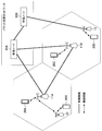
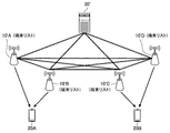
- FIG. 1 is an explanatory diagram illustrating a configuration example of a wireless communication system according to an embodiment of the present disclosure.
- the wireless communication system according to the embodiment of the present disclosure includes an eNodeB 11, a relay node 12, a femtocell base station 13, a UE (User Equipment) 20, and a management node 30.
- ENodeB 11 controls communication with relay node 12 and UE 20 existing in the macro cell formed by eNodeB 11.
- the eNodeB 11A manages scheduling information for communicating with the UE 20A existing in the macro cell, and communicates with the UE 20A according to the scheduling information.
- eNodeB11A manages the scheduling information for communicating with the relay node 12 which exists in a macrocell, and the scheduling information for the relay node 12 and UE20B to communicate.
- Each eNodeB 11 is connected via a wired communication path called an X2 interface.
- Each eNodeB 11 is connected to the management node 30A via a wired communication path called an S1 interface.
- Each eNodeB 11 can communicate with other eNodeBs, management nodes 30, and the like using these interfaces.
- the relay node 12 relays communication between the eNodeB 11 and the UE 20 according to scheduling information managed by the eNodeB 11. Specifically, the relay node 12 receives the signal transmitted from the eNodeB 11 in the downlink, and transmits the amplified signal to the UE 20 using the frequency-time according to the scheduling information. By performing such relaying, the relay node 12 can increase the signal-to-noise ratio compared to the case where the signal is directly transmitted from the eNodeB 11 to the UE 20 near the cell edge.
- the femtocell base station 13 is a base station that forms a cell having a maximum transmission power smaller than that of the eNodeB 11 and smaller than that of the macro cell.
- the femtocell base station 13 is assumed to be arranged in a home or office, and forms a CSG (Closed Subscriber Group) that can be accessed only from the UE 20 of a user in the family, for example.
- CSG Cellular Subscriber Group
- the femtocell base station 13 is connected to the management node 30B, and can communicate with the eNodeB 11 via a packet switching network such as ADSL. Note that the femtocell base station 13 may communicate with the eNodeB 11 via a wireless link.
- the management node 30A is connected to each eNodeB 11 via a backbone network.
- the management node 30A may have a function as an MME (Mobile Management Entity) or a function as a Serving Gateway.
- the management node 30A receives management information indicating the state of the macro cell formed by each eNodeB 11 from each eNodeB 11, and controls communication in the macro cell formed by each eNodeB 11 based on this management information.
- the function of the management node 30A may be distributed and implemented in a plurality of physically separated configurations.
- the management node 30 ⁇ / b> B is connected to the femtocell base station 13 and manages communication by the femtocell base station 13.
- the UE 20 is a wireless terminal that communicates with a base station such as the eNodeB 11, the relay node 12, and the femtocell base station 13 as described above.
- the data transmitted and received by the UE 20 includes audio data, music data such as music, lectures, and radio programs, still image data such as photographs, documents, pictures, and charts, movies, television programs, video programs, and games. Examples include moving image data such as images.
- 1 shows an example in which the UE 20 is a smartphone, the UE 20 is a mobile phone, a PC (Personal computer), a portable music player, a portable game machine, a home music player, a home game.
- An information processing apparatus having a wireless communication function such as a computer may be used.
- a network called HetNet is formed in which large and small cells are arranged to overlap each other. According to this HetNet, it is possible to improve the communication capacity of the entire area by covering the locally generated communication traffic with a small cell, which was difficult to cover with only a large cell such as a macro cell.
- a base station 10 communication control devices such as the eNodeB 11, the relay node 12, and the femtocell base station 13 that form a HetNet are collectively referred to as a base station 10 as necessary.
- the base station 10 is not limited to the eNodeB 11, the relay node 12, and the femtocell base station 13.
- the base station 10 may be a hot zone base station or an RRH (Remote RadioHead) cell base station.
- the hot zone base station is a base station whose maximum transmission power is smaller than eNodeB11.
- the hot zone base station communicates with the eNodeB 11 using an interface such as X2 or S1 of the backbone network.
- the hot zone base station forms an OSG (Open Subscriber Group) that can be accessed from any UE 20.
- OSG Open Subscriber Group
- the RRH cell base station is connected to the eNodeB 11 via an optical fiber.
- eNodeB11 can transmit a signal via an optical fiber to the RRH cell base station arrange
- the functions of the control system are implemented in the eNodeB 11, and the eNodeB 11 selects an optimal transmission form according to the distribution of the UEs 20.
- the above-described eNodeB 11 is open to all UEs 20 and permits connections from all UEs 20.
- the UE 20 can communicate over a wide range by expanding the macro cell by such eNodeB 11.
- a base station that groups UEs 20 and permits only access from specific UEs 20.
- a base station is called a CSG (Closed Subscriber Group) cell.
- CSG Cellular Subscriber Group
- the CSG cell prevents access congestion by the UE 20 and realizes high-quality and high-speed communication.
- the base station 10 can also connect a specific UE 20 with priority over other UEs 20 by grouping the UEs 20.
- the allocation of communication resources at each time / location can be made efficient, and the communication quality of a specific user or a specific area can be improved.
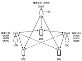
- FIG. 2 is an explanatory view showing an example in which only access of a specific UE 20 is permitted by grouping.
- a case is considered in which the base station 10A does not perform grouping and the base stations 10B and 10C perform grouping.
- the base stations 10B and 10C have a terminal list indicating the UE 20 that is permitted to access, and the terminal list of the base station 10B includes UEs 20A, 20B, and 20C, and the terminal list of the base station 10C includes UEs 20A, 20D. And 20E.
- the base station 10A can communicate with any of the UEs 20A, 20B, and 20D.
- the base station 10B can communicate with the UEs 20A and 20B, but the UE 20D does not communicate with the UE 20D because the UE 20D is not included in the terminal list.
- the base station 10C can communicate with the UEs 20A and 20D, but the UE 20B is not included in the terminal list, and therefore does not communicate with the UE 20B.
- FIG. 3 is an explanatory diagram showing an example of a protocol related to access to the base stations 10 that are grouping the UEs 20.
- the base station 10 inquires of the terminal list to the base station 10 to check whether or not the base station 10 can be connected (S52), the base station 10 includes the UE 20 in the terminal list. It is confirmed whether or not it is (S54). Then, the base station 10 notifies the UE 20 of the confirmation result (S56) or performs an operation according to the grouping of the UE 20 on the UE 20.
- FIG. 4 is an explanatory diagram showing another example of a protocol related to access to the base stations 10 that are grouping the UEs 20.
- the example in which the base station 10 has the terminal list has been described.
- the management node 30 may have the terminal list, and both the base station 10 and the management node 30 You may have a terminal list.
- the base station 10 transfers the inquiry to the management node 30. (S62). Then, the management node 30 confirms whether or not the UE 20 is included in the terminal list (S64), and transmits the confirmation result to the base station 10 (S66). The base station 10 transfers the confirmation result received from the management node 30 to the UE 20 (S68).
- a further physical node may intervene between the base station 10 and the management node.
- the intervening physical node is responsible for transferring the inquiry or confirmation result.
- the priority connection of a specific UE 20 can be realized by grouping the UEs 20.
- the base station 10 can realize a priority connection by assigning more communication resources (time, frequency, code, space, etc.) to a specific UE 20 than other UEs.
- this point will be described more specifically with reference to FIG.
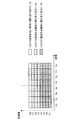
- FIG. 5 is an explanatory diagram showing resource allocation by the base station 10 performing grouping.
- the base station 10 shown in FIG. 5 groups UEs 20 into UEs 20 included in list 1, UEs 20 included in list 2, and other UEs 20, and communication resources for each group are prepared.
- the base station 10 prepares the frequencies F1 to F4 for the group of UEs 20 included in the list 2, and the frequencies F5 to F7 for the group of UEs 20 included in the list 1.
- the frequency F8 is prepared for the other UE20. Therefore, the UE 20 included in the list 2 is given the highest priority, the UE 20 included in the list 1 is given the next highest priority, and the other UEs 20 are given the lowest priority.
- CoMP communication is cooperative communication in which a plurality of base stations 10 cooperate to communicate with the UE 20.
- Examples of this CoMP communication include cooperative transmission, cooperative reception, and cooperative scheduling.
- each of these CoMP communications will be described in detail.
- Coordinated transmission is a method of transmitting information to the target UE 20 from the plurality of base stations 10 to the target UE 20.
- the plurality of base stations 10 use the same communication resource (frequency, time, space, code, etc.) at least partially. Further, the plurality of base stations 10 adjust transmission parameters such as an error correction scheme, an error correction coding rate, a modulation scheme, and weighting of information to be transmitted between the base stations 10.
- transmission parameters such as an error correction scheme, an error correction coding rate, a modulation scheme, and weighting of information to be transmitted between the base stations 10.
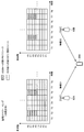
- FIG. 6 is an explanatory diagram showing an example of coordinated transmission for obtaining the space diversity effect by the two base stations 10.
- the same resources are used for frequency and time, but different resources are used for space.
- the same information is transmitted to the UE 20A.
- the base station 10A uses the space weight W1
- the base station 10B uses the space weight W2.
- the spatial weights W1 and W2 are preferably selected so that when the signal is received on the UE 20A side, the combined signal can obtain a diversity effect.
- the base stations 10A and 10B use a communication network such as a packet switching network as shown in FIG. It may be used.
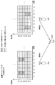
- FIG. 7 is an explanatory diagram showing an example of coordinated transmission for obtaining the spatial multiplexing effect by the two base stations 10.
- the base stations 10A and 10B select communication resources such as a packet-switched network in the same manner as in the example shown in FIG. 6 in order to select the resources and share and control information transmitted from the respective base stations.
- a network or a wired communication path may be used.
- a plurality of base stations 10 receive signals transmitted from the target UE 20, and the plurality of base stations 10 exchange received signals or collect received signals at predetermined locations to decode information. It is a method to do. At this time, the plurality of base stations 10 allocate the same communication resources (frequency, time, space, code, etc.) to the UE 20 at least in part. Thereby, since the effect of the spatial reception diversity by the several base station 10 is acquired, the reception quality of the uplink of a communication system can be improved, for example.
- FIG. 8 is an explanatory diagram showing an example of cooperative reception for obtaining the space diversity effect by the two base stations 10.
- base station 10A and base station 10B when performing base station 10A and base station 10B for coordinated reception to obtain a spatial diversity effect, the same frequency and time resources are allocated to UE 20A, and UE 20A uses the allocated resources.
- Base station 10A and base station 10B attempt to decode information by transferring each received signal to a predetermined location or by exchanging between base station 10A and base station 10B. In this way, it is possible to improve reception quality by using reception signals of a plurality of base stations 10 for decoding information.
- the decoding of information may be performed by another device other than the base station 10A and the base station 10B.
- the UE 20A may transmit information using a space weight.
- Coordinated scheduling is a method of adjusting resource allocation in a plurality of base stations 10 that communicate with the target UE 20 so that at least some of the resources allocated to the UE 20 by each base station 10 are different. Thereby, since signals from a plurality of base stations 10 are orthogonal in at least some communication resources, reduction of interference on the UE 20 side is expected.
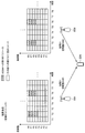
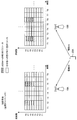
- FIG. 9 is an explanatory diagram showing an example of cooperative scheduling in the frequency direction by the two base stations 10.
- the base stations 10A and 10B use the same resource for time and transmit different information using different resources for frequency. .
- the signals from base stations 10A and 10B are orthogonal, interference can be reduced.
- FIG. 10 is an explanatory diagram showing an example of coordinated scheduling in the time direction by the two base stations 10.
- the base stations 10A and 10B when performing coordinated scheduling in the time direction, transmit different information using the same resource for the frequency but using different resources for the time. .
- the signals from the base stations 10A and 10B are orthogonal, interference can be reduced.
- FIG. 9 and FIG. 10 show examples in which information transmitted from the base stations 10A and 10B is different, the base stations 10A and 10B can also obtain a diversity effect by transmitting the same information.
- . 9 and 10 show transmission from a plurality of base stations 10 to the UE 20, cooperative scheduling for transmission from the UE 20 to the plurality of base stations 10 can also be realized by a similar method.
- CoMP Structured information about CoMP
- the subject may be the base station 10 (serving base station) to which the target UE 20 is connected, or may be another device such as the management node 30 illustrated in FIG.
- the base station 10 communicates information related to grouping of surrounding base stations and the UE 20, and controls CoMP communication based on the information related to this grouping. Is possible.
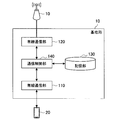
- FIG. 11 is a functional block diagram showing the configuration of the base station 10 according to the first embodiment.
- the base station 10 according to the first embodiment includes a wireless communication unit 110, a wired communication unit 120, a storage unit 130, and a communication control unit 140.
- the radio communication unit 110 functions as a transmission unit for transmitting a radio signal to the UE 20 and a reception unit for receiving a radio signal from the UE 20.
- the wireless communication unit 110 may include a plurality of antennas, an analog processing unit, an AD conversion unit, a digital processing unit, and a decoder as a receiving configuration.
- the wireless communication unit 110 may include an encoder, a digital processing unit, a DA conversion unit, an analog processing unit, and a plurality of antennas as a transmission configuration.
- the wired communication unit 120 functions as a transmission unit for transmitting information to other base stations 10 and management nodes 30 and a reception unit for receiving information from other base stations 10 and management nodes 30.
- the base station 10 according to the present embodiment provides information on grouping and information for implementing CoMP via the wired communication unit 120. Can communicate.
- FIG. 11 shows an example in which the interface with the other base station 10 and the management node 30 is wired, the interface with the other base station 10 and the management node 30 may be wireless.
- the storage unit 130 is a storage medium that stores a program for operating the base station 10 and various information. In particular, when the base station 10 performs grouping of the UEs 20, the storage unit 130 stores a terminal list indicating the contents of grouping.
- the communication control unit 140 controls overall communication in the base station 10 such as communication with the UE 20 by the wireless communication unit 110 and communication with another base station 10 by the wired communication unit 120. Specifically, the communication control unit 140 controls communication of information regarding grouping with other base stations 10. In addition, the communication control unit 140 sets communication parameters for performing CoMP communication with other base stations 10. Further, when the terminal list is stored in the storage unit 130, the communication control unit 140 determines whether communication with the target UE 20 is possible depending on whether the target UE 20 is included in the terminal list. Priority is given to the connection of the target UE 20.
- FIG. 12 is a sequence diagram showing an outline of the operation of the base station 10 according to the present embodiment.
- the base stations 10A and 10B communicate information related to grouping of the UE 20 (S600).
- the information regarding grouping includes information indicating whether grouping is performed, a terminal list, or a terminal list including a specific UE 20. It may be information indicating.
- the base station 10A determines whether or not to perform CoMP with the base station 10B based on the grouping information obtained by the communication of S600 (S700). If the base station 10A determines that CoMP is to be performed, the base station 10A shifts to a procedure for performing CoMP with the base station 10B (S800). On the other hand, if it is determined that CoMP is not performed, the base station 10A performs communication using another method such as one-to-one communication with the UE 20 (S860).
- movement by the base station 10 by this embodiment mentioned above is demonstrated in detail.
- two base stations (10A and 10B) are shown as an example of a plurality of base stations.
- the present embodiment is also applicable to communication by three or more base stations 10.
- each base station 10 performs grouping of the UEs 20 is very important for determining the implementation of CoMP. For this reason, as shown in S600 of FIG. 12, the base station 10 checks whether or not the surrounding base stations 10 are grouping the UEs 20.
- the intervening device plays a role of transferring signaling, ACK / NACK, and the like.
- the communication protocol described below is used for the communication protocol between the base station 10 and the management node 30. Also good.
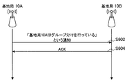
- FIGS. 13 and 14 are sequence diagrams illustrating a first communication example of information regarding grouping.
- the base station 10A notifies the base station 10B that the UE 20 is grouped (S602).
- 10 A of base stations may notify the terminal list which 10 A of base stations have with grouping.
- the base station 10B transmits an ACK to the base station 10A (S604).
- the base station 10B transmits a NACK to the base station 10A as shown in FIG. 14 (S606).
- the base station 10B does not transmit ACK or NACK to the base station 10A (no response).
- the base station 10A may notify the base station 10B again that the UE 20 is grouped (S608).
- a predetermined upper limit may be set for the number of notifications. When the notification reaches a predetermined number of times, the retransmission of the notification may be stopped.
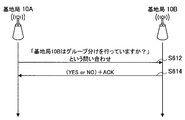
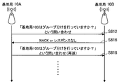
- FIGS. 15 and 16 are sequence diagrams illustrating a second communication example of information regarding grouping.
- the base station 10A inquires of the base station 10B whether or not the UE 20 is grouped by the base station 10B (S612).
- the base station 10B Upon receiving the inquiry from the base station 10A, the base station 10B transmits information indicating whether or not grouping is performed to the base station 10A (S614).
- the base station 10A when the base station 10A receives a NACK from the base station 10B or when there is no response from the base station 10B (S616), the base station 10B performs grouping of the UEs 20 as shown in FIG. It may be inquired again to the base station 10B whether or not (S618).
- a predetermined upper limit may be set for the number of times of inquiries. When the inquiry reaches a predetermined number of times, the retransmission of the inquiry may be stopped.
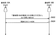
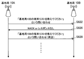
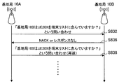
- FIGS. 17 and 18 are sequence diagrams illustrating a third communication example of information related to grouping.
- the base station 10A inquires of the base station 10B about the terminal list of the base station 10B (S622).
- the base station 10B Upon receiving the inquiry from the base station 10A, the base station 10B transmits the terminal list of the base station 10B to the base station 10A (S624).
- the base station 10A when the base station 10A receives a NACK from the base station 10B or when there is no response from the base station 10B (S626), the base station 10B displays the terminal list of the base station 10B in the base station 10B as shown in FIG.
- the inquiry may be made again (S628).
- a predetermined upper limit may be set for the number of times of inquiries. When the inquiry reaches a predetermined number of times, the retransmission of the inquiry may be stopped.
- the base station 10A may execute the control of the third communication example after confirming that the base station 10B performs grouping according to the second communication example.
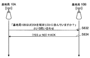
- FIGS. 19 and 20 are sequence diagrams illustrating a fourth communication example of information related to grouping.
- the base station 10A inquires of the base station 10B whether or not the target UE 20X is included in the terminal list of the base station 10B (S632).
- the base station 10B confirms whether or not the UE 20X is included in the terminal list of the base station 10B, and transmits a confirmation result to the base station 10A (S634).
- the base station 10A when the base station 10A receives a NACK from the base station 10B or when there is no response from the base station 10B (S636), as shown in FIG. 20, the target UE 20X is included in the terminal list of the base station 10B.
- the base station 10B may be inquired again whether it is included (S638).
- a predetermined upper limit may be set for the number of times of inquiries. When the inquiry reaches a predetermined number of times, the retransmission of the inquiry may be stopped.
- the base station 10A may execute the control of the fourth communication example after confirming that the base station 10B performs grouping according to the second communication example.
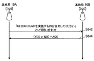
- FIGS. 21 and 22 are sequence diagrams illustrating a fifth communication example of information related to grouping.
- the base station 10A inquires of the base station 10B whether the target UE 20X can participate in CoMP (S642).
- the base station 10B determines whether CoMP for the UE 20X is possible, and transmits the determination result to the base station 10A (S644).
- the base station 10B does not perform grouping
- the base station 10B is open to the UE 20 whose base station 10B is not included in the terminal list. In this case, it may be determined that CoMP for the UE 20X is possible.
- the base station 10A determines whether or not the UE 20X can participate in CoMP as shown in FIG.
- the inquiry may be made again to 10B (S648).
- a predetermined upper limit may be set for the number of times of inquiries.
- the base station 10A may execute the control of the fifth communication example after confirming that the base station 10B performs grouping according to the second communication example. Further, the base station 10A performs control of the fifth communication example after confirming that the target UE 20 is included in the terminal list of the base station 10B by the third communication example or the fourth communication example. May be.
- the communication protocol for information related to grouping described above be implemented particularly in the application layer.
- an arbitrary protocol can be selected for the lower layer of the communication path that actually connects between the base stations 10 and between the management nodes 30, so that the degree of freedom in the configuration of the communication system can be improved.
- the communication protocol is implemented in a cellular system such as LTE (Long Term Evolution)
- LTE Long Term Evolution
- the base station 10 determines whether or not to implement CoMP after communicating information on grouping of the surrounding base stations and the UE 20 and, if so, how to implement CoMP. Is possible. Hereinafter, a specific example of such determination will be described. Note that this CoMP determination may be made by the base station 10 (serving base station) to which the CoMP target UE 20 is connected, or by another base station 10 or the management node 30.
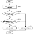
- FIG. 23 is a flowchart illustrating a first determination example regarding CoMP.
- the communication control unit 140 of the base station 10 first confirms information regarding grouping received from surrounding base stations (S702). Then, the communication control unit 140 performs one-to-one communication with the target UE 20 when the base station 10 does not perform grouping (S704) and surrounding base stations perform grouping (S706). Control is performed (S708).
- the communication control unit 140 can communicate with the UE 20 by any method such as CoMP. Is controlled (S710).
- the base station 10 performs normal one-to-one communication with the target UE when there is even one base station that performs grouping in the vicinity. Thereby, signaling for implementing CoMP can be suppressed, and simple communication with the UE 20 can be realized.
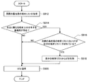
- FIG. 24 is a flowchart illustrating a second determination example regarding CoMP.
- the communication control unit 140 of the base station 10 first confirms information regarding grouping received from surrounding base stations (S712). Then, when the base station 10 performs grouping (S714), the communication control unit 140 controls communication with the UE 20 by an arbitrary method such as one-to-one communication, broadcast communication, or CoMP communication (S716). .
- the communication control unit 140 repeats the processing of S718 to S724 for each surrounding base station. Specifically, in the communication control unit 140, surrounding base stations perform grouping (S718), the target UE 20 is not included in the terminal list of the surrounding base stations (S720), and the surrounding base stations are terminals. When it is not open with respect to UE20 which is not contained in a list
- the communication control unit 140 controls communication requesting CoMP cooperation from surrounding base stations that have not been removed from the CoMP partner (S726).
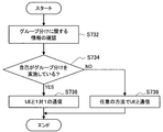
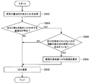
- FIG. 25 is a flowchart illustrating a third determination example regarding CoMP.
- the communication control unit 140 of the base station 10 first checks the information regarding grouping received from the surrounding base stations (S732). Then, when the base station 10 performs grouping (S734), the communication control unit 140 controls one-to-one communication with the target UE 20 (S736). On the other hand, when the base station 10 does not perform grouping (S734), the communication control unit 140 controls communication with the UE 20 by an arbitrary method such as one-to-one communication, broadcast communication, or CoMP communication (S738).
- the base station 10 determines that CoMP is not performed when the base station 10 is a CSG cell such as a femtocell base station. In this case, signaling for implementing CoMP can be suppressed. Further, when the base station 10 operates according to the third determination example, the base station 10 may not have the step (S600) of performing communication related to grouping with the surrounding base stations described with reference to FIGS. .
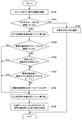
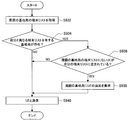
- FIG. 26 is a flowchart illustrating a fourth determination example regarding CoMP.
- the communication control unit 140 of the base station 10 first checks the information regarding grouping received from the surrounding base stations (S742). Then, when the base station 10 does not perform grouping (S744), the communication control unit 140 controls communication with the UE 20 by an arbitrary method such as one-to-one communication or CoMP communication (S746).
- the communication control unit 140 repeats the processing of S748 to S754 for each surrounding base station.
- surrounding base stations perform grouping (S748)
- the target UE 20 is not included in the terminal list of the surrounding base stations (S750), and the surrounding base stations are terminals.
- a surrounding base station is removed from the partner of CoMP (S754).
- the communication control unit 140 controls communication requesting CoMP cooperation from surrounding base stations that have not been removed from the CoMP partner (S756).
- the base station 10 operates as follows in each case.
- base stations that perform grouping are hereinafter referred to as CSG cells, and base stations that are not grouped are referred to as OSG cells.
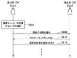
- FIG. 27 and FIG. 28 are sequence diagrams showing signaling for implementing CoMP.
- the base station 10A receives communication resources for implementing CoMP, a spatial weight, a modulation scheme, a coding scheme, etc.
- the transmission / reception parameters are selected or calculated (S802).
- the base station 10A notifies the base station 10B of a selection result such as a transmission / reception parameter (S804).
- the base station 10A performs CoMP according to the communication resource and transmission / reception parameters selected in S802 (S808).
- a specific example of CoMP is as described in “1-2. About CoMP”.
- the base station 10A when the base station 10A receives a NACK from the base station 10B or when there is no response from the base station 10B (S810), the base station 10B sends a selection result such as a transmission / reception parameter to the base station 10B as shown in FIG. Notification is made again (S812).
- a predetermined upper limit may be set for the number of notifications.
- the base station 10A receives a NACK from the base station 10B, or when there is no response from the base station 10B (S810), or when the notification reaches a predetermined number of times, the base station 10A does not perform CoMP and the UE 20 One-to-one communication may be performed, and CoMP may be performed with other surrounding base stations.
- each base station 10 may perform the following processing when implementing CoMP.
- the serving base station 10 notifies the terminal ID of the target UE 20 and information to be transmitted to another base station 10 that performs CoMP. Receiving the notification, each base station 10 transmits the notified information to the UE 20 having the notified terminal ID.
- the serving base station 10 notifies the terminal ID of the target UE 20 and scheduling information to another base station 10 that performs CoMP. Receiving the notification, each base station 10 allocates communication resources (slots and resource blocks) indicated by the notified scheduling information for the UE 20 having the notified terminal ID.
- C The serving base station 10 notifies the terminal ID of the target UE 20 and scheduling information to another base station 10 that performs CoMP.
- each base station 10 allocates a communication resource different from the communication resource indicated by the notified scheduling information for the UE 20 having the notified terminal ID.
- the plurality of base stations 10 that perform CoMP change at least one of the parameters of transmission power, antenna directivity, and antenna weighting from the parameters at the time of past transmission. .
- Each base station 10 may determine these parameters. In this case, each base station 10 may use the previous reception result of the signal transmitted from the UE 20 for setting these parameters. Well, these parameters may be determined by the serving base station 10 or the UE 20.
- At least a part of the plurality of base stations 10 that perform CoMP other than the serving base station 10 decodes and demodulates the received signal and transmits the result to the serving base station 10. .
- At least some of the plurality of base stations 10 that perform CoMP other than the serving base station 10 do not transmit ACK / NACK from the UE 20 to the serving base station 10. Furthermore, the plurality of base stations 10 that perform CoMP do not have to demodulate and decode ACK / NACK, and do not have to perform scheduling for ACK / NACK.
- At least some of the plurality of base stations 10 that perform CoMP do not transmit ACK / NACK for data received from the UE 20.
- At least some of the plurality of base stations 10 that implement CoMP transmit signals to the target UE 20 or receive signals from the UE 20 using the same frequency band or frequency bands having overlapping portions.
- a network in which base stations 10 performing grouping and base stations 10 not performing grouping are mixed such as CSG cells and OSG cells.
- Second Embodiment a mechanism for a plurality of base stations 10 ′ to share the same terminal list is proposed.
- Second Embodiment a use case is assumed in which a plurality of base stations 10 ′ having the same terminal list constitute a communication system. For example, in a relatively large office, a use case is conceivable in which the entire office is covered by a plurality of base stations 10 ′ (small base stations such as femtocell base stations).
- base stations 10'A to 10'D are arranged in the same office, and base stations 10'A to 10'D have the same terminal list.
- the UE 20 included in the terminal list can be connected to any of the base stations 10 'from anywhere in the office.
- the terminal list may be managed by the management node 30 '.
- the base station 10 ′ can communicate with the UE 20 on a one-to-one basis, or can perform CoMP as described in the first embodiment.
- FIG. 30 is a functional block diagram showing the configuration of the base station 10 ′ according to the second embodiment.
- the base station 10 ′ according to the second embodiment includes a wireless communication unit 110, a wired communication unit 120, a storage unit 130, a communication control unit 142, a list comparison unit 150, and a list. And an update unit 160. Since the wireless communication unit 110, the wired communication unit 120, and the storage unit 130 are as described in the first embodiment, detailed description thereof is omitted here.
- the communication control unit 142 controls communication for acquiring the terminal list of the surrounding base station 10 ′ in addition to the function of the communication control unit 140 described in the first embodiment. Further, the communication control unit 142 controls communication requesting update of the terminal list of the surrounding base station 10 ′ as necessary.
- the list comparison unit 150 compares the terminal list of the surrounding base station 10 ′ with the terminal list of the base station 10 ′ stored in the storage unit 130, and has a terminal list different from the terminal list of the base station 10 ′. It is determined whether or not the base station 10 'exists.
- the list comparison unit 150 determines that there is a surrounding base station 10 ′ having a terminal list different from the terminal list of the base station 10 ′
- the list update unit 160 for example, the base station stored in the storage unit 130
- the terminal list of 10 ′ is matched with the terminal list of the surrounding base station 10 ′.
- the communication control unit 142 displays the terminal list of the surrounding base station 10 ′. You may control the communication which requests
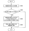
- FIG. 31 is a flowchart showing a first operation example of the base station 10 ′ according to the second embodiment.
- the list comparison unit 150 is stored in the storage unit 130. It is determined whether or not there is a surrounding base station 10 ′ having a terminal list different from the terminal list of the base station 10 ′ (S904).
- the list update unit 160 adds the UE 20 to the terminal list of the base station 10 ′ (S908). Then, the base station 10 'proceeds to a step of communication with the UE 20 (S910).
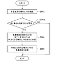
- FIG. 32 is a flowchart showing a second operation example of the base station 10 ′ according to the second embodiment.
- the list comparison unit 150 is stored in the storage unit 130. It is determined whether or not there is a surrounding base station 10 ′ having a terminal list different from the terminal list of the base station 10 ′ (S914).
- the list update unit 160 deletes the UE 20 from the terminal list of the base station 10 ′ (S918). Then, the base station 10 'proceeds to a communication step with the UE 20 (S920).
- the terminal lists of the base station 10 'and the surrounding base stations 10' can be matched by the first operation example and the second operation example described above.
- the terminal list of surrounding base station 10' is updated like the 3rd operation example and 4th operation example which are demonstrated below.
- the terminal lists of the base station 10 ′ and the surrounding base stations 10 ′ can be matched.
- FIG. 33 is a flowchart showing a third operation example of the base station 10 ′ according to the second embodiment.
- the list comparison unit 150 is stored in the storage unit 130. It is determined whether or not there is a surrounding base station 10 ′ having a terminal list different from the terminal list of the base station 10 ′ (S924).
- the communication control unit 142 controls communication requesting the surrounding base station 10 ′ to delete the UE 20 (S928). Then, the base station 10 'proceeds to a communication step with the UE 20 (S930).
- FIG. 34 is a flowchart showing a fourth operation example of the base station 10 ′ according to the second embodiment.
- the list comparison unit 150 is stored in the storage unit 130. It is determined whether or not there is a surrounding base station 10 ′ having a terminal list different from the terminal list of the base station 10 ′ (S934).
- the communication control unit 142 controls communication requesting the surrounding base station 10 ′ to add the UE 20 (S938). Then, the base station 10 'proceeds to a communication step with the UE 20 (S940).
- the base station 10 ' is the main example to match the terminal lists of the plurality of base stations 10'.
- the management node 30 ' is the main body to match the terminal list of the base station 10'. Is also possible.
- the configuration and operation of the management node 30 ′ will be described in detail.
- FIG. 35 is a functional block diagram showing the configuration of the management node 30 '.
- the management node 30 ′ includes a wired communication unit 320, a communication control unit 342, a list comparison unit 350, and a list creation unit 370.
- the wired communication unit 320 functions as a transmission unit for transmitting information to the base station 10 'and a reception unit for receiving information from the base station 10'.
- the wired communication unit 320 receives a terminal list from each base station 10 ′, and transmits the terminal list created by the list creation unit 370 to each base station 10 ′.
- FIG. 35 shows an example in which the interface between the management node 30 ′ and the base station 10 ′ is wired, but the interface between the management node 30 ′ and the base station 10 ′ may be wireless.
- the communication control unit 342 controls overall communication by the wired communication unit 320. For example, the communication control unit 342 controls communication requesting the terminal list to each base station 10 ′, transmission of the terminal list created by the list creation unit 370 to each base station 10 ′, and the like.
- the list comparison unit 350 compares the terminal list of each base station 10 ′ received by the wired communication unit 320, and determines whether there is a terminal list different from the others among the terminal lists of each base station 10 ′. to decide.
- the list creation unit 370 creates a new terminal list based on the terminal list of each base station 10 ′ when it is determined that a terminal list different from the others exists in the terminal list of each base station 10 ′.
- the new terminal list created by the list creation unit 370 is transmitted from the wired communication unit 230 to each base station 10 ′.
- FIG. 36 is a flowchart showing a first operation example of the management node 30 '.
- the management node 30 ′ receives the terminal list from each base station 10 ′ under the control of the communication control unit 342 (S952)
- the list comparison unit 350 displays the terminal list of each base station 10 ′. It is determined whether there is a terminal list different from others (S954).
- the list creation unit 370 newly creates a terminal list including the UEs 20 included in any of the terminal lists of each base station 10 ′ (S956).
- the list creation unit 370 may include And a terminal list consisting of 20D.
- the wired communication unit 320 transmits the terminal list newly created by the list creation unit 370 to each base station 10 '(S958).
- FIG. 37 is a flowchart showing a second operation example of the management node 30 '.
- the management node 30 ′ receives the terminal list from each base station 10 ′ under the control of the communication control unit 342 (S962)
- the list comparison unit 350 displays the terminal list of each base station 10 ′. It is determined whether there is a terminal list different from the others (S964).
- the list creation unit 370 newly creates a terminal list including the UEs 20 included in all the terminal lists of the respective base stations 10 '(S966).
- the list creation unit 370 includes the UEs 20A and 20B. Create a terminal list.
- the wired communication unit 320 transmits the terminal list newly created by the list creation unit 370 to each base station 10 '(S968).
- the base station 10 ′ or the management node 30 ′ is the main body and updates the terminal list.
- the terminal list may be updated periodically by the base station 10 ′ or the management node 30 ′, but the base station 10 ′ or the management node 30 ′ responds to a request from the UE 20 as will be described below.
- the terminal list may be updated.
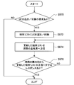
- FIG. 38 is a flowchart showing terminal list update processing by the base station 10 '. As illustrated in FIG. 38, when the radio communication unit 110 of the base station 10 ′ receives a request for addition / deletion to the terminal list of the UE 20 from the UE 20 (S970), the UE 20 is added to the terminal list of the storage unit 130. / Delete UE20 from the terminal list (S972).
- the wired communication unit 120 of the base station 10 transmits the terminal list updated by the list update unit 160 to the surrounding base stations 10' (S974). Thereafter, when there is a response to the terminal list from the surrounding base station 10 ′, the base station 10 ′ notifies the UE 20 of the completion of the update and ends the update process (S 976). On the other hand, when the update notification is not received from the surrounding base station 10 'by the wired communication unit 120, the wired communication unit 120 transmits the updated terminal list to the surrounding base station 10' again (S974).
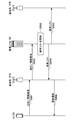
- FIG. 39 is a sequence diagram showing the update process of the terminal list by the base station 10 'from another viewpoint.
- the base station 10′A when the UE 20 requests the base station 10′A to add / delete the UE 20 to / from the terminal list (S981), the base station 10′A sends the request to the other base station 10′B. Transmit (S982).
- S982 Transmit
- FIG. 39 only two base stations 10 ′ are shown. However, when a larger number of base stations 10 ′ constitute a communication system, each base station 10 ′ sequentially issues the request in a relay format, for example. It may be transferred.
- each base station 10 ′ that has received a request for addition / deletion to the terminal list of the UE 20 updates the terminal list according to the request (S 983, S 984). Then, each base station 10 'transmits an update notification indicating that the terminal list has been updated (S985, S986).
- each base station 10 ′ individually updates the terminal list.
- one device such as the management node 30 ′ updates the terminal list. May be.
- FIG. 40 is a sequence diagram showing terminal list update processing by the management node 30 '.
- the base station 10′A transmits the request to the management node 30 ′ ( Then, the management node 30 ′ updates the terminal list in response to the request (S993), and transmits the updated terminal list to each base station 10 ′ (S994, S995). Thereafter, the base station 10'A transmits an update notification indicating that the terminal list has been updated to the UE 20 (S996).
- the base station 10′A or the management node 30 ′ may update the terminal list in response to a request from the UE 20, for example, or may request a request from the outside of the communication system or the base station 10′A.
- the terminal list may be updated according to a human operation on the management node 30 ′.
- each step in the processing of the base station 10, the management node 30, and the like in this specification does not necessarily have to be processed in time series in the order described as a sequence diagram or a flowchart.
- each step in the processing of the base station 10, the management node 30, etc. may be processed in an order different from the order described as the flowchart, or may be processed in parallel.
- the communication control device according to (1) wherein the communication control unit controls communication inquiring whether or not the other communication control device performs the terminal grouping.
- the communication control unit controls communication for inquiring whether the other communication control device has a terminal list including the target wireless terminal as the specific wireless terminal, or any one of (1) to (3)
- the communication control unit controls communication for inquiring whether or not to participate in cooperative communication in cooperation with the other communication control device for communication with a target wireless terminal. Any one of (1) to (4) The communication control device according to one item. (6) The communication control unit controls transmission of information indicating whether or not the communication control device performs the terminal grouping in response to an inquiry from the other communication control device. (1) to (5) The communication control apparatus according to any one of the above. (7) The communication control unit controls transmission of information indicating whether or not the communication control device has a terminal list including the target wireless terminal as the specific wireless terminal in response to an inquiry from the other communication control device. The communication control device according to any one of (1) to (6).
- the communication control device When the communication control device has a terminal list including the target wireless terminal as the specific wireless terminal, the communication control unit responds to an inquiry from the other communication control device as to whether or not to participate in cooperative communication.
- the communication control device according to any one of (1) to (7), which controls transmission of information indicating participation in the cooperative communication
- the communication control device includes: A list comparison unit that compares the terminal list indicating the terminal grouping received from the other communication control device and the terminal list of the communication control device; If the list comparison unit determines that both lists are different, a list update unit that matches the terminal list of the communication control device with the terminal list received from the other communication control device;
- the communication control device according to any one of (1) to (8), further comprising: (10)
- the communication control device includes: Further comprising a list comparison unit for comparing the terminal list indicating the terminal grouping received from the other communication control device and the terminal list of the communication control device; When the list comparison unit determines that the two lists are different, the communication control unit requests the terminal list of the other communication control
- the communication control device includes: A list comparison unit for comparing a plurality of terminal lists indicating the terminal groupings received from each of a plurality of other communication control devices; When the list comparison unit determines that the terminal list different from the other terminal list is included in the plurality of terminal lists, a list creation unit that creates a new terminal list; Further comprising The communication control unit controls transmission of the new terminal list created by the list creation unit to the plurality of other communication control devices, according to any one of (1) to (8). Communication control device. (12) The communication according to any one of (1) to (11), wherein the specific terminal is a terminal that is permitted to connect to the communication control apparatus or a terminal that is preferentially connected to the communication control apparatus.
- Control device (13) A communication control method for controlling communication of information related to terminal grouping for distinguishing operations for a specific wireless terminal and other wireless terminals, which is communication with another communication control apparatus. (14) Computer A communication control unit for controlling communication of information related to terminal grouping for distinguishing operations for a specific wireless terminal and other wireless terminals, which is communication with another communication control device; Program to function as (15) A first communication control device; A second communication control device; With The first communication control device includes: A communication system comprising: a communication control unit that controls communication of information related to terminal grouping for distinguishing operations for a specific wireless terminal and other wireless terminals, which is communication with the second communication control device.
Landscapes
- Engineering & Computer Science (AREA)
- Signal Processing (AREA)
- Computer Networks & Wireless Communication (AREA)
- Databases & Information Systems (AREA)
- Multimedia (AREA)
- Mobile Radio Communication Systems (AREA)
Priority Applications (5)
| Application Number | Priority Date | Filing Date | Title |
|---|---|---|---|
| BR112013029362A BR112013029362A2 (pt) | 2011-05-20 | 2012-04-17 | aparelho e método de controle de comunicação, programa e, sistema de comunicação |
| EP12789963.1A EP2712229B1 (en) | 2011-05-20 | 2012-04-17 | Communications control device, communications control method, program, and communications system |
| CN201280023108.1A CN103535069B (zh) | 2011-05-20 | 2012-04-17 | 通信控制设备、通信控制方法、程序以及通信系统 |
| KR1020137029664A KR20140035365A (ko) | 2011-05-20 | 2012-04-17 | 통신 제어 장치, 통신 제어 방법, 프로그램 및 통신 시스템 |
| US14/112,318 US10264473B2 (en) | 2011-05-20 | 2012-04-17 | Communication control apparatus, communication control method, and communication system |
Applications Claiming Priority (2)
| Application Number | Priority Date | Filing Date | Title |
|---|---|---|---|
| JP2011113675A JP2012244477A (ja) | 2011-05-20 | 2011-05-20 | 通信制御装置、通信制御方法、プログラムおよび通信システム |
| JP2011-113675 | 2011-05-20 |
Publications (1)
| Publication Number | Publication Date |
|---|---|
| WO2012160908A1 true WO2012160908A1 (ja) | 2012-11-29 |
Family
ID=47216993
Family Applications (1)
| Application Number | Title | Priority Date | Filing Date |
|---|---|---|---|
| PCT/JP2012/060332 WO2012160908A1 (ja) | 2011-05-20 | 2012-04-17 | 通信制御装置、通信制御方法、プログラムおよび通信システム |
Country Status (7)
Cited By (2)
| Publication number | Priority date | Publication date | Assignee | Title |
|---|---|---|---|---|
| WO2015022750A1 (ja) * | 2013-08-15 | 2015-02-19 | 富士通株式会社 | 無線通信システムにおける通信装置および通信方法 |
| CN104412688A (zh) * | 2013-06-25 | 2015-03-11 | 华为技术有限公司 | 一种数据调度的方法、装置、基站及系统 |
Families Citing this family (5)
| Publication number | Priority date | Publication date | Assignee | Title |
|---|---|---|---|---|
| US10129751B2 (en) * | 2012-05-25 | 2018-11-13 | Comcast Cable Communications, Llc | Wireless gateway supporting public and private networks |
| JP6140183B2 (ja) * | 2012-11-09 | 2017-05-31 | 京セラ株式会社 | 移動通信システム、移動通信方法及びアンカー無線基地局 |
| CN106413114B (zh) | 2013-05-22 | 2019-11-26 | 华为技术有限公司 | 异构网络中的控制设备 |
| US9198078B1 (en) * | 2013-12-11 | 2015-11-24 | Sprint Spectrum L.P. | Managing signaling overhead in a wireless multicast system |
| JP7230023B2 (ja) * | 2018-06-28 | 2023-02-28 | 株式会社Nttドコモ | 端末及び無線通信方法 |
Citations (5)
| Publication number | Priority date | Publication date | Assignee | Title |
|---|---|---|---|---|
| JP2010213273A (ja) | 2009-03-06 | 2010-09-24 | Ntt Docomo Inc | Csg情報伝送方法および装置 |
| WO2010125738A1 (ja) * | 2009-04-28 | 2010-11-04 | 三菱電機株式会社 | 移動体通信システム |
| JP2011501525A (ja) | 2007-10-12 | 2011-01-06 | クゥアルコム・インコーポレイテッド | ホスト端末デバイスからゲスト端末デバイスへのフェムトセル情報のトランザクションを可能にするためのシステムおよび方法 |
| JP2011019247A (ja) * | 2005-08-01 | 2011-01-27 | Ubiquisys Ltd | 基地局 |
| JP2011087089A (ja) * | 2009-10-14 | 2011-04-28 | Ntt Docomo Inc | 移動通信方法及び無線基地局 |
Family Cites Families (39)
| Publication number | Priority date | Publication date | Assignee | Title |
|---|---|---|---|---|
| US20080015955A1 (en) * | 1999-05-19 | 2008-01-17 | I.D. Systems, Inc. | Mobile asset data management system |
| US6412002B1 (en) * | 1999-11-15 | 2002-06-25 | Ncr Corporation | Method and apparatus for selecting nodes in configuring massively parallel systems |
| DE60135165D1 (de) * | 2000-08-15 | 2008-09-11 | Nortel Networks Ltd | Optischer Dienst-Agent zur Verwaltung von Kommunikationsdiensten in einem optischen Kommunikationssystem |
| GB0103918D0 (en) * | 2001-02-16 | 2001-04-04 | Pathfinder Tech Resources Ltd | Mobile telephone operation |
| US7263086B2 (en) * | 2002-11-12 | 2007-08-28 | Nokia Corporation | Method and system for providing location-based services in multiple coverage area environments |
| US20050261970A1 (en) * | 2004-05-21 | 2005-11-24 | Wayport, Inc. | Method for providing wireless services |
| US7304976B2 (en) * | 2004-10-13 | 2007-12-04 | Virginia Tech Intellectual Properties, Inc. | Method and apparatus for control and routing of wireless sensor networks |
| US7751430B2 (en) * | 2005-07-14 | 2010-07-06 | Motorola, Inc. | Self optimization of time division duplex (TDD) timing and adaptive modulation thresholds |
| US7801542B1 (en) * | 2005-12-19 | 2010-09-21 | Stewart Brett B | Automatic management of geographic information pertaining to social networks, groups of users, or assets |
| US20070209059A1 (en) * | 2006-03-03 | 2007-09-06 | Moore John A | Communication system employing a control layer architecture |
| JP4702110B2 (ja) * | 2006-03-03 | 2011-06-15 | 日本電気株式会社 | 無線通信システム、無線基地局、無線通信制御装置、プログラム、および経路制御方法 |
| DE102006021831A1 (de) * | 2006-05-10 | 2007-11-15 | Rohde & Schwarz Gmbh & Co. Kg | Funkübertragungssystem und Verfahren für dessen Betrieb |
| US20080186933A1 (en) * | 2007-02-05 | 2008-08-07 | Charles Arthur Willman | Approach For Providing Wireless Network Services Using Wireless Access Point Groups |
| US8019331B2 (en) * | 2007-02-26 | 2011-09-13 | Kineto Wireless, Inc. | Femtocell integration into the macro network |
| US8638806B2 (en) * | 2007-05-25 | 2014-01-28 | Hand Held Products, Inc. | Wireless mesh point portable data terminal |
| CN101494851B (zh) * | 2008-01-24 | 2012-04-04 | 华为技术有限公司 | 用户终端标识信息的发送方法和设备 |
| WO2009110572A1 (ja) * | 2008-03-05 | 2009-09-11 | 日本電気株式会社 | 移動通信システム、基地局、送信電力制御方法及びプログラム |
| WO2009109684A1 (es) * | 2008-03-05 | 2009-09-11 | Media Patents, S. L. | Procedimiento para monitorizar o gestionar equipos conectados a una red de datos |
| CN101645729A (zh) * | 2008-08-08 | 2010-02-10 | 夏普株式会社 | 下行蜂窝系统的多天线多基站合作方法及基站 |
| US8046016B2 (en) * | 2008-08-27 | 2011-10-25 | Motorola Solutions, Inc. | Indicating availability of RF resources at a peer base station in a two-way peer-to-peer communication system |
| CN101686557B (zh) * | 2008-09-22 | 2014-04-02 | 华为技术有限公司 | 一种多小区调度信息发送方法、装置及用户设备 |
| US8693442B2 (en) * | 2008-09-22 | 2014-04-08 | Blackberry Limited | Multi-site MIMO cooperation in cellular network |
| US8340235B2 (en) * | 2008-09-25 | 2012-12-25 | Research In Motion Limited | X-MIMO systems with multi-transmitters and multi-receivers |
| JP5606674B2 (ja) * | 2008-12-12 | 2014-10-15 | 横河電機株式会社 | ゲートウェイ装置及びこれを用いた無線制御ネットワーク管理システム |
| US8289368B2 (en) * | 2008-12-15 | 2012-10-16 | Avaya Inc. | Intelligent grouping and synchronized group switching for multimedia conferencing |
| US9516553B2 (en) | 2008-12-23 | 2016-12-06 | Qualcomm Incorporated | Handover control based on closed subscriber group subscription information |
| US9351193B2 (en) * | 2009-01-28 | 2016-05-24 | Headwater Partners I Llc | Intermediate networking devices |
| JP5278017B2 (ja) * | 2009-02-10 | 2013-09-04 | セイコーエプソン株式会社 | ネットワーク接続制御システム及び方法 |
| KR101569031B1 (ko) | 2009-03-23 | 2015-11-13 | 엘지전자 주식회사 | Home (e)NodeB에 대한 단말의 접속을 제어하는 방법 |
| US8599701B2 (en) * | 2009-04-16 | 2013-12-03 | Qualcomm Incorporated | Systems, methods and devices to enable management of wireless network resources |
| US8954077B2 (en) | 2009-05-04 | 2015-02-10 | Qualcomm Incorporated | Access mode-based access control |
| JP5457451B2 (ja) * | 2009-06-30 | 2014-04-02 | パナソニック株式会社 | データ交換処理装置およびデータ交換処理方法 |
| US8386876B2 (en) * | 2009-08-14 | 2013-02-26 | Sharp Laboratories Of America, Inc. | Transmission of different redundancy versions on different degrees of freedom |
| US8745023B2 (en) * | 2009-10-28 | 2014-06-03 | Louis H. Libin | System and method for content browsing using a non-realtime connection |
| CA2794744C (en) * | 2010-04-01 | 2016-05-17 | Research In Motion Limited | Methods and apparatus to transfer management control of a client between servers |
| GB2480689B (en) * | 2010-05-28 | 2013-05-08 | Toshiba Res Europ Ltd | Radio resource management in femtocells |
| US8713589B2 (en) * | 2010-12-23 | 2014-04-29 | Microsoft Corporation | Registration and network access control |
| CA2827569A1 (en) * | 2011-02-17 | 2012-08-23 | Blackberry Limited | Cooperative relay-enabled wireless network that optimizes packet delay |
| US20120230189A1 (en) * | 2011-03-08 | 2012-09-13 | Medium Access Systems Private Limited | System and method of transferring Wi-Fi clients between SSIDs |
-
2011
- 2011-05-20 JP JP2011113675A patent/JP2012244477A/ja not_active Ceased
-
2012
- 2012-04-17 WO PCT/JP2012/060332 patent/WO2012160908A1/ja active Application Filing
- 2012-04-17 CN CN201280023108.1A patent/CN103535069B/zh not_active Expired - Fee Related
- 2012-04-17 KR KR1020137029664A patent/KR20140035365A/ko not_active Withdrawn
- 2012-04-17 EP EP12789963.1A patent/EP2712229B1/en not_active Not-in-force
- 2012-04-17 BR BR112013029362A patent/BR112013029362A2/pt not_active IP Right Cessation
- 2012-04-17 US US14/112,318 patent/US10264473B2/en not_active Expired - Fee Related
Patent Citations (5)
| Publication number | Priority date | Publication date | Assignee | Title |
|---|---|---|---|---|
| JP2011019247A (ja) * | 2005-08-01 | 2011-01-27 | Ubiquisys Ltd | 基地局 |
| JP2011501525A (ja) | 2007-10-12 | 2011-01-06 | クゥアルコム・インコーポレイテッド | ホスト端末デバイスからゲスト端末デバイスへのフェムトセル情報のトランザクションを可能にするためのシステムおよび方法 |
| JP2010213273A (ja) | 2009-03-06 | 2010-09-24 | Ntt Docomo Inc | Csg情報伝送方法および装置 |
| WO2010125738A1 (ja) * | 2009-04-28 | 2010-11-04 | 三菱電機株式会社 | 移動体通信システム |
| JP2011087089A (ja) * | 2009-10-14 | 2011-04-28 | Ntt Docomo Inc | 移動通信方法及び無線基地局 |
Cited By (3)
| Publication number | Priority date | Publication date | Assignee | Title |
|---|---|---|---|---|
| CN104412688A (zh) * | 2013-06-25 | 2015-03-11 | 华为技术有限公司 | 一种数据调度的方法、装置、基站及系统 |
| WO2015022750A1 (ja) * | 2013-08-15 | 2015-02-19 | 富士通株式会社 | 無線通信システムにおける通信装置および通信方法 |
| JPWO2015022750A1 (ja) * | 2013-08-15 | 2017-03-02 | 富士通株式会社 | 無線通信システムにおける通信装置および通信方法 |
Also Published As
| Publication number | Publication date |
|---|---|
| US20140044053A1 (en) | 2014-02-13 |
| CN103535069B (zh) | 2017-12-26 |
| JP2012244477A (ja) | 2012-12-10 |
| EP2712229B1 (en) | 2018-05-30 |
| EP2712229A4 (en) | 2015-01-07 |
| CN103535069A (zh) | 2014-01-22 |
| BR112013029362A2 (pt) | 2019-09-24 |
| US10264473B2 (en) | 2019-04-16 |
| EP2712229A1 (en) | 2014-03-26 |
| KR20140035365A (ko) | 2014-03-21 |
Similar Documents
| Publication | Publication Date | Title |
|---|---|---|
| JP5760685B2 (ja) | 通信制御装置、通信制御方法、プログラムおよび通信システム | |
| JP5515559B2 (ja) | 通信システム、基地局、および通信装置 | |
| WO2012160908A1 (ja) | 通信制御装置、通信制御方法、プログラムおよび通信システム | |
| CN102308652B (zh) | 基于无线接口的接入点资源协商以及分配 | |
| JP5504970B2 (ja) | 管理サーバ、通信システム、通信端末、および中継装置 | |
| JP5521638B2 (ja) | 通信システム、中継装置、管理サーバ、および通信端末 | |
| JP6020671B2 (ja) | 中小規模基地局および通信端末 | |
| EP3061311A1 (en) | Apparatus and methods for cellular network communication based on plural mobile cores | |
| WO2013140448A1 (ja) | 無線通信システム、無線局および無線通信方法 | |
| CN107278353B (zh) | 移动通信系统、方法及基站 | |
| US20240259788A1 (en) | Enabling an efficient transition of multiple mobile devices from one wireless telecommunication network to another | |
| JP6288152B2 (ja) | 無線通信システム、無線基地局、無線端末、および無線通信方法 | |
| US20250125866A1 (en) | Dynamic scanning rates for satellite network coverage | |
| US20250247466A1 (en) | Device configurations for redirecting voice to sms messages over satellite networks | |
| US20250247712A1 (en) | Limited communication capability notifications | |
| US12341909B2 (en) | Authenticating a user interacting with a wireless telecommunication network via a non-internet connected phone | |
| US20250247688A1 (en) | Limited communication capability notifications | |
| US20250132811A1 (en) | Device settings for satellite networks | |
| US20250081218A1 (en) | Frequency layer management using ota performance tests of a mobile device | |
| WO2025160407A1 (en) | Limited communication capability notifications | |
| JP2014131346A (ja) | 管理サーバ、通信システム、通信端末、中継装置および基地局 |
Legal Events
| Date | Code | Title | Description |
|---|---|---|---|
| 121 | Ep: the epo has been informed by wipo that ep was designated in this application |
Ref document number: 12789963 Country of ref document: EP Kind code of ref document: A1 |
|
| WWE | Wipo information: entry into national phase |
Ref document number: 14112318 Country of ref document: US |
|
| ENP | Entry into the national phase |
Ref document number: 20137029664 Country of ref document: KR Kind code of ref document: A |
|
| WWE | Wipo information: entry into national phase |
Ref document number: 2012789963 Country of ref document: EP |
|
| NENP | Non-entry into the national phase |
Ref country code: DE |
|
| REG | Reference to national code |
Ref country code: BR Ref legal event code: B01A Ref document number: 112013029362 Country of ref document: BR |
|
| ENP | Entry into the national phase |
Ref document number: 112013029362 Country of ref document: BR Kind code of ref document: A2 Effective date: 20131113 |