WO2012160672A1 - Transformer - Google Patents
Transformer Download PDFInfo
- Publication number
- WO2012160672A1 WO2012160672A1 PCT/JP2011/061984 JP2011061984W WO2012160672A1 WO 2012160672 A1 WO2012160672 A1 WO 2012160672A1 JP 2011061984 W JP2011061984 W JP 2011061984W WO 2012160672 A1 WO2012160672 A1 WO 2012160672A1
- Authority
- WO
- WIPO (PCT)
- Prior art keywords
- transformer
- magnetic flux
- mounting members
- electromagnetic shield
- coil
- Prior art date
Links
Images


Classifications
-
- H—ELECTRICITY
- H01—ELECTRIC ELEMENTS
- H01F—MAGNETS; INDUCTANCES; TRANSFORMERS; SELECTION OF MATERIALS FOR THEIR MAGNETIC PROPERTIES
- H01F27/00—Details of transformers or inductances, in general
- H01F27/34—Special means for preventing or reducing unwanted electric or magnetic effects, e.g. no-load losses, reactive currents, harmonics, oscillations, leakage fields
- H01F27/36—Electric or magnetic shields or screens
- H01F27/366—Electric or magnetic shields or screens made of ferromagnetic material
Definitions
- the present invention relates to a transformer, and more particularly to a structure for supporting an electromagnetic shield included in the transformer.
- Oil-filled transformers generally include a transformer body and a tank that houses the transformer body.
- the transformer body includes a high voltage coil, a low voltage coil, and an iron core.
- the tank is filled with insulating oil, and the transformer body is immersed in the insulating oil.
- the tank is generally made of steel.
- an electromagnetic shield is attached to the inner wall of the tank.
- Patent Document 1 discloses an electromagnetic shield used for a transformer.
- the electromagnetic shield includes a plurality of laminated magnetic thin plates and a pair of metal plates sandwiching the plurality of magnetic thin plates.
- a plurality of seats are provided to attach the electromagnetic shield to the tank. These seat plates are connected to the electromagnetic shield body and the inner wall of the tank by welding. As a result, the electromagnetic shield is attached to the tank.
- a closed circuit is formed by two seat plates, one of a pair of metal plates sandwiching a plurality of magnetic thin plates, and a steel plate to which the seat plates are attached.
- the purpose of the present invention is to more effectively reduce transformer losses.
- a transformer according to an aspect of the present invention includes a tank and a transformer body housed in the tank.
- the transformer body includes an iron core and a coil wound around the iron core.
- the transformer further includes a plurality of electromagnetic shields.
- Each of the plurality of electromagnetic shields includes a plurality of magnetic thin plates stacked on each other, a pair of metal plates sandwiching the plurality of magnetic thin plates, and a plurality of attachment members each connected to the pair of metal plates.
- the plurality of attachment members are arranged at positions where the sum of leakage magnetic fluxes interlinking regions between the first and second attachment members adjacent to each other among the plurality of attachment members becomes zero.
- stray load loss of the transformer can be reduced. Therefore, according to the present invention, the loss of the transformer can be reduced.
- FIG. 2 is a cross-sectional view of a part of the transformer taken along line II-II in FIG. 1.
- FIG. 7 is a diagram showing one unit of the electromagnetic shields 5-1 to 5-7 shown in FIG.
- FIG. 4 is a diagram for explaining leakage magnetic flux generated from a coil 2. It is a figure explaining the electromagnetic shield which concerns on the comparative example of this Embodiment, and the circulating current which arises in the electromagnetic shield. It is a figure explaining one structural example of the electromagnetic shield which concerns on embodiment of this invention, and the leakage magnetic flux which links the area
- FIG. 6 is a diagram illustrating an example of a support structure for an electromagnetic shield according to Embodiment 2.
- FIG. It is the figure which showed the other example of the support structure of the electromagnetic shield which concerns on Embodiment 2.
- FIG. 6 is a diagram illustrating an example of a support structure for an electromagnetic shield according to Embodiment 2.
- FIG. It is the figure which showed the other example of the support structure of the electromagnetic shield which concerns on Embodiment 2.
- FIG. 1 is a schematic diagram of a transformer according to an embodiment of the present invention.
- transformer 50 includes a plurality of iron cores 1 and a plurality of coils 2 wound around the plurality of iron cores 1.
- the plurality of iron cores 1 and the plurality of coils 2 constitute a transformer body.
- Each of the plurality of iron cores 1 has an annular shape.
- the coil 2 is wound around two adjacent iron cores 1.
- the insulator 3 covers the coil 2.
- the coil 2 includes a high voltage coil 21 and low voltage coils 22 and 23.
- the high voltage coil 21 is disposed between the low voltage coils 22 and 23.
- the transformer 50 further has a tank 4 for accommodating the transformer body. Although not shown, the inside of the tank 4 is filled with insulating oil. During operation of the transformer 50, insulating oil is circulated to cool the transformer body.
- the tank 4 is formed of a steel material.
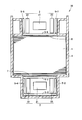
- FIG. 2 is a cross-sectional view of a part of the transformer along the line II-II in FIG.
- the transformer 50 includes an iron core 1, a coil 2, electromagnetic shields 5-1 to 5-7, a tongue wedge 6, and a tongue support 7.
- the insulator 3 is not shown in FIG.
- the tongue wedge 6 is arranged on the uppermost surface of the iron core 1.
- the tongue support 7 is disposed so as to penetrate the opening of the coil 2 and supports the iron core 1.
- the tongue support 7 is passed between the flanges at the bottom of the tank.
- the tongue wedge 6 and the tongue support 7 are made of steel.
- the iron core 1 is fixed by the tongue wedge 6 and the tongue support 7.
- the high voltage coil 21 and the low voltage coils 22 and 23 are arranged coaxially.
- FIG. 3 is a diagram showing one unit of the electromagnetic shields 5-1 to 5-7 shown in FIG. 2 and 3, the electromagnetic shield 5 includes a plurality of magnetic thin plates 8 stacked on each other, metal plates 9-1 and 9-2 sandwiching the plurality of magnetic thin plates 8, and a plurality of seat plates 10-. 1 to 10-3.
- the metal plates 9-1 and 9-2 and the seat plates 10-1 to 10-3 are made of iron or stainless steel.
- Seat plates 10-1 to 10-3 function as mounting members. Each of the seat plates 10-1 to 10-3 is connected to the metal plates 9-1 and 9-2 by welding. The seat plates 10-1 to 10-3 are further attached to the inner wall of the tank 4, the tongue wedge 6 or the tongue support 7 by welding. Thus, the electromagnetic shield 5 is attached at a desired position. Specifically, the electromagnetic shield 5-1 is attached to the tongue support 7. The electromagnetic shields 5-2, 5-3, and 5-4 are attached to the inner wall of the tank 4 (lower tank). The electromagnetic shields 5-5 and 5-7 are attached to the inner wall of the tank 4. The electromagnetic shield 5-6 is attached to the tongue wedge 6. In this embodiment, a metal plate is shown as the mounting member. However, the shape of the mounting member is not limited as shown in FIG.
- the electromagnetic shields 5-1 to 5-7 are provided to prevent the leakage magnetic flux from entering the tank 4, the tongue wedge 6 or the tongue support 7.
- FIG. 4 is a diagram for explaining the leakage magnetic flux generated from the coil 2.
- the density of the leakage magnetic flux reaches a positive peak value or a negative peak value in a region between the high voltage coil and the low voltage coil.
- the density of the leakage magnetic flux reaches a positive peak value in the region between the high voltage coil 21 and the low voltage coil 22.
- the density of the leakage magnetic flux reaches a negative peak value.
- the relationship between the two regions and the positive peak value and the negative peak value of the leakage magnetic flux density may be opposite to the above relationship.
- FIG. 5 is a diagram for explaining an electromagnetic shield according to a comparative example of the present embodiment and a circulating current generated in the electromagnetic shield.
- the hatched area in the graph indicates the integrated value of the magnetic flux density of the leakage magnetic flux interlinking the area between the two seat plates 10a and 10b (in the subsequent figures). The same).
- the integrated value of the magnetic flux density over the range of the positive value of the magnetic flux density is different from the absolute value of the integrated value of the magnetic flux density over the range of the negative value of the magnetic flux density. For this reason, the integrated value of the magnetic flux density of the leakage magnetic flux interlinking the region between the two seat plates 10a and 10b does not become zero.
- the circulating current 11 flows in a closed circuit formed by the seat plates 10a and 10b, the tongue wedge 6 and the metal plate 9-1.
- the circulating current is also applied to the closed circuit located on the opposite side to the side shown in FIG. 5, that is, the closed circuit formed by the seat plates 10a and 10b, the tongue wedge 6 and the metal plate 9-2. Flowing. Further, the same phenomenon occurs in the electromagnetic shield attached to the tongue support 7 or the tank 4. Stray load loss occurs when the circulating current 11 flows through the closed circuit.
- the plurality of seat plates 10 are arranged so that the total sum of the leakage magnetic flux interlinking the region between the two seat plates is zero.
- the arrangement of the plurality of seat plates 10 will be described in detail below.
- FIG. 6 is a diagram for explaining one configuration example of the electromagnetic shield according to the embodiment of the present invention and the leakage magnetic flux interlinking the region between the two seat plates of the electromagnetic shield.
- One of the two seats is attached at a position corresponding to the positive peak value of the leakage flux density, and the other is attached at a position corresponding to the negative peak value of the leakage flux density.
- the positive integral value of magnetic flux density and the absolute value of the negative integral value of magnetic flux density become substantially equal. Therefore, the sum total of the leakage magnetic flux interlinking the region between the seat plates 10a and 10b can be made substantially zero.
- the density of the leakage magnetic flux reaches a positive peak value in the region between the high voltage coil 21 and the low voltage coil 22.
- the density of the leakage magnetic flux reaches a negative peak value in the region between the high voltage coil 21 and the low voltage coil 23. Therefore, the period L of the density distribution of the leakage magnetic flux can be estimated based on the arrangement of the high voltage coil 21 and the low voltage coils 22 and 23. As a result, the distance d between the two seats can be determined. Further, the positions of the plurality of seat plates 10 can be determined.
- the position of the seat plate may exactly coincide with the peak position of the magnetic flux density, or may be in the vicinity of the peak position.
- FIG. 7 is a diagram for explaining another configuration example of the electromagnetic shield according to the present embodiment and a leakage magnetic flux interlinking the region between the two seat plates of the electromagnetic shield.
- the positive integral value of the magnetic flux density is almost equal to the absolute value of the negative integral value of the magnetic flux density. Therefore, the sum total of the leakage magnetic flux interlinking the region between the seat plates 10a and 10b can be made substantially zero. As a result, stray load loss can be reduced, and transformer loss can be effectively reduced.
- the position of the seat plate is equal to the position corresponding to the positive peak value of the magnetic flux density of the leakage magnetic flux.
- the position of the seat plate need not be limited as described above.
- the integrated value of the magnetic flux density during one period of the magnetic flux density distribution is zero. Therefore, according to the configuration shown in FIG. 7, the degree of freedom in the arrangement of the electromagnetic shield can be increased.
- the distance d between the two seats can be determined according to the following equation.
- m is an integer of 1 or more.
- m is an integer of 1 or more.
- two adjacent seat plates among the plurality of seat plates 10 are attached to a steel material such as a tank wedge as follows. That is, one of the two seats is attached at a position corresponding to the positive peak of the leakage magnetic flux density, and the other is attached at a position corresponding to the negative peak of the leakage magnetic flux density. Thereby, it is possible to reduce the total sum of the leakage magnetic fluxes interlinking the region between the two seat plates (ideally, the total sum of the leakage magnetic fluxes becomes zero).
- the position of the seat plate need not be limited to the position of the peak of the leakage magnetic flux density.
- the electromagnetic shield according to the embodiment of the present invention is attached to at least the tongue portion (the tongue wedge 6 and the tongue support 7). That is, the electromagnetic shield according to the embodiment of the present invention is preferably provided in a region between the iron core and the coil.
- the magnetic flux density of the leakage magnetic flux interlinking the region between the two seat plates is particularly large in the tongue portion. Therefore, the loss of a transformer can be effectively reduced by attaching the electromagnetic shield which concerns on embodiment of this invention to a tongue part.
- the electromagnetic shield according to the embodiment of the present invention is attached not only to the tongue portion but also to the inner wall of the tank 4.
- the electromagnetic shield attached to the tank 4 has a function of preventing leakage magnetic flux from the coil from entering the tank 4. Therefore, the loss of the transformer can be further reduced.
- the distance d between the two seats of the electromagnetic shield is determined to be, for example, 1/2 times or 1 time the period of the density distribution of the leakage magnetic flux.
- the support strength of the electromagnetic shield may decrease.
- a spacer is disposed between two seat plates. Thereby, the fall of the support strength of an electromagnetic shield can be prevented.
- the spacer is formed of an insulator.
- FIG. 8 is a view showing an example of a support structure for an electromagnetic shield according to the second embodiment.
- the insulating spacer 31 is inserted into a part of the region between the two seat plates. That is, in this configuration, the support strength of the electromagnetic shield is increased by the point support by the insulating spacer 31.
- FIG. 9 is a view showing another example of a support structure for an electromagnetic shield according to the second embodiment.
- the insulating spacer 32 is inserted so as to fill the entire area between the two seat plates. That is, in this configuration, the support strength of the electromagnetic shield is increased by the surface support by the insulating spacer 31.
- interval d between the two seats is the same as the interval according to the first embodiment, and therefore the following description will not be repeated.
- the loss of the transformer can be effectively reduced as in the first embodiment. Furthermore, according to Embodiment 2, even when the space
Landscapes
- Engineering & Computer Science (AREA)
- Power Engineering (AREA)
- Regulation Of General Use Transformers (AREA)
Abstract
Description
図1は、本発明の実施の形態に係る変圧器の概略図である。図1を参照して、変圧器50は、複数の鉄心1と、複数の鉄心1にそれぞれ巻回される複数のコイル2とを有する。複数の鉄心1および複数のコイル2は変圧器本体を構成する。 [Embodiment 1]
FIG. 1 is a schematic diagram of a transformer according to an embodiment of the present invention. Referring to FIG. 1,
ここでmは1以上の整数である。mが奇数の場合には、複数の座板10のうちの隣り合う2つの座板はタンクウェッジ等の鋼材に次のように取り付けられることが好ましい。すなわち、2つの座板の一方は、漏れ磁束の密度の正のピークに対応する位置に取り付けられ、他方は、漏れ磁束の密度の負のピークに対応する位置に取り付けられる。これにより、2つの座板の間の領域を鎖交する漏れ磁束の総和を小さくする(理想的には漏れ磁束の総和が0になる)ことが可能である。一方、mが偶数の場合には、座板の位置を漏れ磁束の密度のピークの位置に限定しなくてもよい。 d = (L / 2) × m
Here, m is an integer of 1 or more. When m is an odd number, it is preferable that two adjacent seat plates among the plurality of
実施の形態2に係る変圧器の全体的な構成は図1および図2に示された構成と同様である。さらに、実施の形態2に係る電磁シールドの構成は、図3に示された構成と同様である。 [Embodiment 2]
The overall configuration of the transformer according to the second embodiment is the same as the configuration shown in FIGS. 1 and 2. Furthermore, the configuration of the electromagnetic shield according to the second embodiment is the same as the configuration shown in FIG.
Claims (7)
- タンク(4)と、
前記タンク(4)に収容された変圧器本体とを備え、前記変圧器本体は、鉄心(1)および前記鉄心(1)に巻回されたコイル(2)を含み、
複数の電磁シールド(5-1,5-2,5-3,5-4,5-5,5-6,5-7)をさらに備え、
前記複数の電磁シールド(5-1,5-2,5-3,5-4,5-5,5-6,5-7)の各々は、
互いに積層された複数の磁性薄板(8)と、
前記複数の磁性薄板(8)を挟む1対の金属板(9-1,9-2)と、
各々が前記1対の金属板(9-1,9-2)に接続された複数の取付部材(10,10-1,10-2,10-3,10a,10b)とを含み、
前記複数の取付部材(10,10-1,10-2,10-3,10a,10b)は、前記複数の取付部材(10,10-1,10-2,10-3,10a,10b)のうちの互いに隣り合う第1および第2の取付部材(10a,10b)の間の領域を鎖交する漏れ磁束の総和が0となる位置に配置される、変圧器。 Tank (4),
A transformer body housed in the tank (4), the transformer body including an iron core (1) and a coil (2) wound around the iron core (1),
A plurality of electromagnetic shields (5-1, 5-2, 5-3, 5-4, 5-5, 5-6, 5-7);
Each of the plurality of electromagnetic shields (5-1, 5-2, 5-3, 5-4, 5-5, 5-6, 5-7)
A plurality of magnetic thin plates (8) laminated together;
A pair of metal plates (9-1, 9-2) sandwiching the plurality of magnetic thin plates (8);
A plurality of mounting members (10, 10-1, 10-2, 10-3, 10a, 10b) each connected to the pair of metal plates (9-1, 9-2),
The plurality of mounting members (10, 10-1, 10-2, 10-3, 10a, 10b) are the plurality of mounting members (10, 10-1, 10-2, 10-3, 10a, 10b). The transformer is arranged at a position where the sum of leakage magnetic fluxes interlinking regions between the first and second mounting members (10a, 10b) adjacent to each other becomes zero. - 前記変圧器は、
前記鉄心(1)と前記コイル(2)との間に配置されて前記鉄心(1)を固定する固定部材(6,7)をさらに備え、
前記複数の電磁シールド(5-1,5-2,5-3,5-4,5-5,5-6,5-7)は、第1の電磁シールド(5-1,5-6)を含み、前記第1の電磁シールド(5-1,5-6)の前記複数の取付部材(10,10-1,10-2,10-3,10a,10b)は、前記固定部材(6,7)に取り付けられる、請求項1に記載の変圧器。 The transformer is
A fixing member (6, 7) disposed between the iron core (1) and the coil (2) to fix the iron core (1);
The plurality of electromagnetic shields (5-1, 5-2, 5-3, 5-4, 5-5, 5-6, 5-7) are the first electromagnetic shields (5-1, 5-6). The plurality of mounting members (10, 10-1, 10-2, 10-3, 10a, 10b) of the first electromagnetic shield (5-1, 5-6) include the fixing member (6). , 7). The transformer according to claim 1. - 前記複数の電磁シールド(5-1,5-2,5-3,5-4,5-5,5-6,5-7)は、第2の電磁シールド(5-2,5-3,5-4,5-5,5-7)を含み、前記第2の電磁シールド(5-2,5-3,5-4,5-5,5-7)の前記複数の取付部材(10,10-1,10-2,10-3,10a,10b)は、前記タンク(4)の内壁に取り付けられる、請求項2に記載の変圧器。 The plurality of electromagnetic shields (5-1, 5-2, 5-3, 5-4, 5-5, 5-6, 5-7) include a second electromagnetic shield (5-2, 5-3, 5-4, 5-5, 5-7), and the plurality of mounting members (10) of the second electromagnetic shield (5-2, 5-3, 5-4, 5-5, 5-7) , 10-1, 10-2, 10-3, 10a, 10b) according to claim 2, mounted on the inner wall of the tank (4).
- 前記コイル(2)は、同軸上に配置された第1および第2の低圧コイル(22,23)ならびに高圧コイル(21)を含み、
前記高圧コイル(21)は、前記第1の低圧コイル(22)と前記第2の低圧コイル(23)との間に配置され、
前記第1および第2の低圧コイル(22,23)ならびに前記高圧コイル(21)によって、前記漏れ磁束の分布が定義され、
前記第1および第2の取付部材(10a,10b)の間の間隔(d)は、前記分布の半分の周期を整数倍した値である、請求項1に記載の変圧器。 The coil (2) includes first and second low voltage coils (22, 23) and a high voltage coil (21) arranged coaxially,
The high voltage coil (21) is disposed between the first low voltage coil (22) and the second low voltage coil (23),
The leakage flux distribution is defined by the first and second low voltage coils (22, 23) and the high voltage coil (21),
The transformer (1) according to claim 1, wherein the distance (d) between the first and second mounting members (10a, 10b) is a value obtained by multiplying a half period of the distribution by an integer. - 前記第1および第2の取付部材(10a,10b)の間の前記間隔(d)は、前記半分の周期の奇数倍の値に等しく、
前記第1の取付部材は、前記漏れ磁束の磁束密度の正のピーク値に対応する位置に配置され、
前記第2の取付部材は、前記漏れ磁束の前記磁束密度の負のピーク値に対応する位置に配置される、請求項4に記載の変圧器。 The spacing (d) between the first and second mounting members (10a, 10b) is equal to an odd multiple of the half period;
The first mounting member is disposed at a position corresponding to a positive peak value of the magnetic flux density of the leakage magnetic flux,
The transformer according to claim 4, wherein the second mounting member is disposed at a position corresponding to a negative peak value of the magnetic flux density of the leakage magnetic flux. - 前記第1および第2の取付部材(10a,10b)の間の前記間隔(d)は、前記半分の周期の偶数倍の値に等しい、請求項4に記載の変圧器。 The transformer according to claim 4, wherein the distance (d) between the first and second mounting members (10a, 10b) is equal to an even multiple of the half period.
- 前記第1および第2の取付部材(10a,10b)の間に挿入されたスペーサ(31,32)をさらに備え、
前記スペーサ(31,32)は絶縁物により形成される、請求項4に記載の変圧器。 A spacer (31, 32) inserted between the first and second mounting members (10a, 10b);
The transformer according to claim 4, wherein the spacers (31, 32) are formed of an insulator.
Priority Applications (4)
| Application Number | Priority Date | Filing Date | Title |
|---|---|---|---|
| US13/984,041 US8928446B2 (en) | 2011-05-25 | 2011-05-25 | Transformer |
| CN201180070465.9A CN103503092B (en) | 2011-05-25 | 2011-05-25 | Transformer |
| JP2011549778A JP5010055B1 (en) | 2011-05-25 | 2011-05-25 | Transformer |
| PCT/JP2011/061984 WO2012160672A1 (en) | 2011-05-25 | 2011-05-25 | Transformer |
Applications Claiming Priority (1)
| Application Number | Priority Date | Filing Date | Title |
|---|---|---|---|
| PCT/JP2011/061984 WO2012160672A1 (en) | 2011-05-25 | 2011-05-25 | Transformer |
Publications (1)
| Publication Number | Publication Date |
|---|---|
| WO2012160672A1 true WO2012160672A1 (en) | 2012-11-29 |
Family
ID=46844508
Family Applications (1)
| Application Number | Title | Priority Date | Filing Date |
|---|---|---|---|
| PCT/JP2011/061984 WO2012160672A1 (en) | 2011-05-25 | 2011-05-25 | Transformer |
Country Status (4)
| Country | Link |
|---|---|
| US (1) | US8928446B2 (en) |
| JP (1) | JP5010055B1 (en) |
| CN (1) | CN103503092B (en) |
| WO (1) | WO2012160672A1 (en) |
Cited By (1)
| Publication number | Priority date | Publication date | Assignee | Title |
|---|---|---|---|---|
| WO2020194580A1 (en) * | 2019-03-27 | 2020-10-01 | 三菱電機株式会社 | Stationary induction device |
Families Citing this family (4)
| Publication number | Priority date | Publication date | Assignee | Title |
|---|---|---|---|---|
| DE102013226226A1 (en) * | 2012-12-21 | 2014-06-26 | Robert Bosch Gmbh | Induktivladespulenvorrichtung |
| WO2017002225A1 (en) * | 2015-07-01 | 2017-01-05 | 三菱電機株式会社 | Transformer |
| EP3654354A1 (en) * | 2018-11-14 | 2020-05-20 | ABB Schweiz AG | Internal supports for shell form transformers |
| WO2022194328A2 (en) * | 2021-03-19 | 2022-09-22 | REDUR GmbH & Co. KG | Low voltage shielding element, low voltage current transformer, low voltage current transformer arrangement and low voltage electrical arrangement |
Citations (6)
| Publication number | Priority date | Publication date | Assignee | Title |
|---|---|---|---|---|
| JPS5632423U (en) * | 1979-08-22 | 1981-03-30 | ||
| JPS5681914A (en) * | 1979-12-10 | 1981-07-04 | Hitachi Ltd | Stationary induction electrical apparatus |
| JPS60219717A (en) * | 1984-04-16 | 1985-11-02 | Mitsubishi Electric Corp | Magnetic shield of stationary induction apparatus |
| JPS6310533U (en) * | 1986-07-09 | 1988-01-23 | ||
| JPS63215028A (en) * | 1987-03-04 | 1988-09-07 | Mitsubishi Electric Corp | Method of assembling core for stationary induction apparatus |
| JP2001244128A (en) * | 2000-02-25 | 2001-09-07 | Hitachi Ltd | Static induction electrical apparatus |
Family Cites Families (8)
| Publication number | Priority date | Publication date | Assignee | Title |
|---|---|---|---|---|
| US4156862A (en) * | 1978-02-21 | 1979-05-29 | Westinghouse Electric Corp. | Electrical inductive apparatus having non-magnetic flux shields |
| US4231074A (en) * | 1978-09-18 | 1980-10-28 | General Electric Company | Zero sequence current source for transformer having a nonwound tertiary |
| JPS5632423A (en) | 1979-08-28 | 1981-04-01 | Sunstar Inc | Promotion of thrombolytic activity of urokinase with crude drug extract, and pharmaceutical preparation containing the same |
| JPS6310533A (en) | 1986-07-02 | 1988-01-18 | Matsushita Electric Ind Co Ltd | Sealed metal mold |
| JP3311391B2 (en) * | 1991-09-13 | 2002-08-05 | ヴィエルティー コーポレーション | Leakage inductance reducing transformer, high frequency circuit and power converter using the same, and method of reducing leakage inductance in transformer |
| JPH0883721A (en) | 1994-09-12 | 1996-03-26 | Toshiba Corp | Three-phase transformer |
| JPH10116741A (en) * | 1996-10-14 | 1998-05-06 | Toshiba Corp | Magnetic shield for stationary induction unit and fixing method therefor |
| BRPI1008599A2 (en) * | 2009-02-18 | 2016-03-15 | Abb Research Ltd | magnetic shunt, magnetic shunt arrangement and force device |
-
2011
- 2011-05-25 CN CN201180070465.9A patent/CN103503092B/en not_active Expired - Fee Related
- 2011-05-25 JP JP2011549778A patent/JP5010055B1/en not_active Expired - Fee Related
- 2011-05-25 WO PCT/JP2011/061984 patent/WO2012160672A1/en active Application Filing
- 2011-05-25 US US13/984,041 patent/US8928446B2/en not_active Expired - Fee Related
Patent Citations (6)
| Publication number | Priority date | Publication date | Assignee | Title |
|---|---|---|---|---|
| JPS5632423U (en) * | 1979-08-22 | 1981-03-30 | ||
| JPS5681914A (en) * | 1979-12-10 | 1981-07-04 | Hitachi Ltd | Stationary induction electrical apparatus |
| JPS60219717A (en) * | 1984-04-16 | 1985-11-02 | Mitsubishi Electric Corp | Magnetic shield of stationary induction apparatus |
| JPS6310533U (en) * | 1986-07-09 | 1988-01-23 | ||
| JPS63215028A (en) * | 1987-03-04 | 1988-09-07 | Mitsubishi Electric Corp | Method of assembling core for stationary induction apparatus |
| JP2001244128A (en) * | 2000-02-25 | 2001-09-07 | Hitachi Ltd | Static induction electrical apparatus |
Cited By (1)
| Publication number | Priority date | Publication date | Assignee | Title |
|---|---|---|---|---|
| WO2020194580A1 (en) * | 2019-03-27 | 2020-10-01 | 三菱電機株式会社 | Stationary induction device |
Also Published As
| Publication number | Publication date |
|---|---|
| JPWO2012160672A1 (en) | 2014-07-31 |
| JP5010055B1 (en) | 2012-08-29 |
| CN103503092B (en) | 2016-05-25 |
| US8928446B2 (en) | 2015-01-06 |
| US20130314199A1 (en) | 2013-11-28 |
| CN103503092A (en) | 2014-01-08 |
Similar Documents
| Publication | Publication Date | Title |
|---|---|---|
| EP2590187B1 (en) | Amorphous core transformer | |
| JP5010055B1 (en) | Transformer | |
| US10403427B2 (en) | Transformer | |
| JP6464582B2 (en) | Magnetic circuit parts | |
| JP6397349B2 (en) | Three-phase five-legged iron core and stationary electromagnetic equipment | |
| JP6613784B2 (en) | Transformer core support structure and core support method | |
| TWI595517B (en) | Ground induction electrical appliances | |
| JP2019149517A (en) | Electromagnetic apparatus | |
| WO2016092612A1 (en) | Stationary induction device | |
| JP5701120B2 (en) | Magnetic shielding device for transformer | |
| JP2011023488A (en) | Stationary induction apparatus | |
| CN204066967U (en) | Shell type reactor | |
| KR101573813B1 (en) | Low loss type hybrid transformer, and manufacturing method thereof | |
| JP2013065701A (en) | Static apparatus | |
| JP2018107224A (en) | Stationary induction electric apparatus | |
| JP5815116B2 (en) | Stationary induction equipment | |
| JP6504936B2 (en) | Transformer | |
| JP6491835B2 (en) | Static induction machine | |
| JP2009088084A (en) | Stationary induction apparatus | |
| JP6253963B2 (en) | Stationary equipment | |
| JP7149908B2 (en) | Static induction device | |
| JP2008103416A (en) | Stationary inductive electric apparatus | |
| JP7356852B2 (en) | Iron core for stationary induction appliances | |
| CN210668035U (en) | Electric reactor | |
| JP2012004345A (en) | Stationary induction apparatus and method of manufacturing the same |
Legal Events
| Date | Code | Title | Description |
|---|---|---|---|
| ENP | Entry into the national phase |
Ref document number: 2011549778 Country of ref document: JP Kind code of ref document: A |
|
| 121 | Ep: the epo has been informed by wipo that ep was designated in this application |
Ref document number: 11866306 Country of ref document: EP Kind code of ref document: A1 |
|
| WWE | Wipo information: entry into national phase |
Ref document number: 13984041 Country of ref document: US |
|
| NENP | Non-entry into the national phase |
Ref country code: DE |
|
| 122 | Ep: pct application non-entry in european phase |
Ref document number: 11866306 Country of ref document: EP Kind code of ref document: A1 |