WO2012157939A2 - 망 부하 감소를 위한 푸시 서비스 제공 시스템 및 방법 - Google Patents
망 부하 감소를 위한 푸시 서비스 제공 시스템 및 방법 Download PDFInfo
- Publication number
- WO2012157939A2 WO2012157939A2 PCT/KR2012/003793 KR2012003793W WO2012157939A2 WO 2012157939 A2 WO2012157939 A2 WO 2012157939A2 KR 2012003793 W KR2012003793 W KR 2012003793W WO 2012157939 A2 WO2012157939 A2 WO 2012157939A2
- Authority
- WO
- WIPO (PCT)
- Prior art keywords
- client
- push
- message
- push service
- interlocking unit
- Prior art date
- Legal status (The legal status is an assumption and is not a legal conclusion. Google has not performed a legal analysis and makes no representation as to the accuracy of the status listed.)
- Ceased
Links
Images



Classifications
-
- H—ELECTRICITY
- H04—ELECTRIC COMMUNICATION TECHNIQUE
- H04L—TRANSMISSION OF DIGITAL INFORMATION, e.g. TELEGRAPHIC COMMUNICATION
- H04L67/00—Network arrangements or protocols for supporting network services or applications
- H04L67/01—Protocols
- H04L67/10—Protocols in which an application is distributed across nodes in the network
- H04L67/1001—Protocols in which an application is distributed across nodes in the network for accessing one among a plurality of replicated servers
- H04L67/1034—Reaction to server failures by a load balancer
-
- H—ELECTRICITY
- H04—ELECTRIC COMMUNICATION TECHNIQUE
- H04L—TRANSMISSION OF DIGITAL INFORMATION, e.g. TELEGRAPHIC COMMUNICATION
- H04L51/00—User-to-user messaging in packet-switching networks, transmitted according to store-and-forward or real-time protocols, e.g. e-mail
- H04L51/21—Monitoring or handling of messages
- H04L51/224—Monitoring or handling of messages providing notification on incoming messages, e.g. pushed notifications of received messages
-
- G—PHYSICS
- G06—COMPUTING OR CALCULATING; COUNTING
- G06F—ELECTRIC DIGITAL DATA PROCESSING
- G06F15/00—Digital computers in general; Data processing equipment in general
- G06F15/16—Combinations of two or more digital computers each having at least an arithmetic unit, a program unit and a register, e.g. for a simultaneous processing of several programs
-
- H—ELECTRICITY
- H04—ELECTRIC COMMUNICATION TECHNIQUE
- H04L—TRANSMISSION OF DIGITAL INFORMATION, e.g. TELEGRAPHIC COMMUNICATION
- H04L41/00—Arrangements for maintenance, administration or management of data switching networks, e.g. of packet switching networks
- H04L41/06—Management of faults, events, alarms or notifications
- H04L41/0654—Management of faults, events, alarms or notifications using network fault recovery
- H04L41/0668—Management of faults, events, alarms or notifications using network fault recovery by dynamic selection of recovery network elements, e.g. replacement by the most appropriate element after failure
-
- H—ELECTRICITY
- H04—ELECTRIC COMMUNICATION TECHNIQUE
- H04L—TRANSMISSION OF DIGITAL INFORMATION, e.g. TELEGRAPHIC COMMUNICATION
- H04L67/00—Network arrangements or protocols for supporting network services or applications
- H04L67/01—Protocols
- H04L67/10—Protocols in which an application is distributed across nodes in the network
- H04L67/1001—Protocols in which an application is distributed across nodes in the network for accessing one among a plurality of replicated servers
- H04L67/1029—Protocols in which an application is distributed across nodes in the network for accessing one among a plurality of replicated servers using data related to the state of servers by a load balancer
-
- H—ELECTRICITY
- H04—ELECTRIC COMMUNICATION TECHNIQUE
- H04L—TRANSMISSION OF DIGITAL INFORMATION, e.g. TELEGRAPHIC COMMUNICATION
- H04L67/00—Network arrangements or protocols for supporting network services or applications
- H04L67/14—Session management
- H04L67/142—Managing session states for stateless protocols; Signalling session states; State transitions; Keeping-state mechanisms
-
- H—ELECTRICITY
- H04—ELECTRIC COMMUNICATION TECHNIQUE
- H04L—TRANSMISSION OF DIGITAL INFORMATION, e.g. TELEGRAPHIC COMMUNICATION
- H04L67/00—Network arrangements or protocols for supporting network services or applications
- H04L67/50—Network services
- H04L67/55—Push-based network services
-
- H—ELECTRICITY
- H04—ELECTRIC COMMUNICATION TECHNIQUE
- H04W—WIRELESS COMMUNICATION NETWORKS
- H04W28/00—Network traffic management; Network resource management
- H04W28/02—Traffic management, e.g. flow control or congestion control
- H04W28/08—Load balancing or load distribution
- H04W28/0846—Load balancing or load distribution between network providers, e.g. operators
-
- H—ELECTRICITY
- H04—ELECTRIC COMMUNICATION TECHNIQUE
- H04W—WIRELESS COMMUNICATION NETWORKS
- H04W4/00—Services specially adapted for wireless communication networks; Facilities therefor
- H04W4/12—Messaging; Mailboxes; Announcements
Definitions
- the present invention relates to a push service providing system and method, and more particularly, in delivering a push message provided from a service providing device to a client through a push service device, connection with the client due to a failure of the push service device.
- the present invention relates to a push service providing system and a method for allowing a push service device or a client to selectively reconnect.
- the service provider and the client are not directly connected, the connection is maintained with the push server through a daemon built in the client, and the service provider pushes a message or pushes a notification. If you send a message, the central push server receives it and sends it to the client.
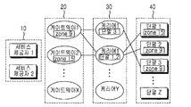
- FIG. 1 is a view showing the configuration of a conventional push service providing system.
- the gateway 20 and the carrier 30 are established between the plurality of service providers 10 and the plurality of terminals 40 so that an application program installed in the plurality of terminals 40 is connected to the service provider 10.
- the structure in which the service provider 10 is connected by connecting to the carrier 30 and the gateway 20 without having to individually connect is shown.
- the gateway 20 is a relay device for connecting with a plurality of service providers 10
- the carrier 30 is a device for connecting with a plurality of terminals 40, and the increase of the service provider 10 and the terminal 40 is performed. It can be extended according to the structure.
- the terminal 40 since the terminal 40 is managed based on a zone, the terminal 40 is assigned to the carrier 30 determined according to preset information when interworking with the carrier 30. .
- This method has a high processing speed, but when the terminal 40 rapidly increases in the same zone, the terminal 40 to be accommodated in one carrier 30 is biased, and thus a load is easily applied.
- connection with the terminal 40 when the connection with the terminal 40 is abnormally terminated due to the failure of the carrier 30, the connection between the carrier 30 and the terminal 40 is attempted. Since the connection attempt is performed by the carrier 30 or the terminal 40 at the same time, an increase in the number of the carrier 30 or the terminal 40 causes an instantaneous load of the network.
- the present invention discloses a method for distributing network load caused by abnormal connection termination between a push server and a terminal.
- the present invention has been made in view of the above circumstances, and an object of the present invention is to provide a push service device when the connection with the client is terminated due to a failure of the push service device performing the connection with the client device. Another object is to provide a push service providing system and method for reducing network load caused by a reconnection attempt between a push service device and a client by selectively attempting to reconnect at a client.
- the predetermined criterion corresponds to a case where there is a new push message to be transmitted from the push service device to the client, or a keep alive time designated by the client to confirm a connection activation state with the push service device. It is characterized by.
- Push service device for achieving the above object, SP (Service Provider) interworking unit for connecting with the service providing device; A client interlocking unit for connecting to a client and transmitting a push message received from the SP interlocking unit to the one or more clients; And a new push message to be transmitted to the client from the SP interlocking unit or a keep-alive message from the client when the connection between the client interworking unit and the client is abnormally terminated. and a controller for attempting to reconnect to the client through a client interlocking unit.
- SP Service Provider
- the push service device if a failure occurs in the client linkage, characterized in that it further comprises a secondary client linkage to back up the configuration information of the client linkage of the failure occurs on behalf of the function of the client linkage.
- Push service device for achieving the above object, SP (Service Provider) interworking unit for connecting with the service providing device; A client interlocking unit which connects to a client and transmits a push message received from the SP interlocking unit to the client; An auxiliary client interlocking unit for backing up setting information from the client interlocking unit to perform a function of the client interlocking unit; And a controller for backing up the setting information of the client interworking unit in which the failure occurs to the auxiliary client interlocking unit when the connection between the client interlocking unit and the one or more clients is abnormally terminated due to a failure of the client interlocking unit.
- SP Service Provider
- the interlocking unit when a keep-alive message is received from the client in a state of backing up configuration information from the client interlocking unit, transmits a response message to the client to the client and sends a response message to the client. Characterized in that to perform reconnection.
- the auxiliary client interworking unit characterized in that for receiving the keep-alive message for each period corresponding to the preset keep-alive time.
- a push service providing method comprising: a push message delivery step of connecting a push service device to a client and delivering a push message provided from the service providing device to the client; An abnormal termination confirmation step of confirming, by the push service device, that the connection with the client is abnormally terminated as a failure occurs; Reconnection determination to confirm whether the push service device has received a push message to be transmitted from the service providing device to the client or whether the client is a designated keep alive time to confirm the connection activation state with the push service device. step; And a reconnection execution step in which the push service device or the client attempts to reconnect with each other when the push service device receives a push message to be transmitted to the client or the keep alive time.
- the abnormal termination check step if it is confirmed that the connection with the client is abnormally terminated, characterized in that for backing up the configuration information related to the connection with the client.
- the push service apparatus transmits a message for reconnection to the client based on the backed up configuration information. Characterized in that the reconnection to the client.
- the client when the keep alive time, the client sends a keep alive message to the push service device having the backup configuration information, and sends a response message to the transmitted keep alive message. And reconnect to the push service device based on the result.
- the push service device or client By selectively reconnecting at, there is an effect of reducing the network load caused by the reconnection attempt between the push service device and the client.
- FIG. 1 is a view showing the configuration of a conventional push service providing system.
- FIG. 2 is a diagram illustrating a network configuration of a push service providing system according to an exemplary embodiment of the present invention.
- FIG. 3 is a detailed configuration diagram of a push service device according to an embodiment of the present invention.
- FIG. 4 is a diagram illustrating a connection setting configuration between a push service device and a client according to an embodiment of the present invention.
- FIG. 5 is a flowchart illustrating a push service providing method for reducing network load according to an embodiment of the present invention.
- FIG. 6 is a flowchart illustrating a push service providing method for reducing a network load according to another embodiment of the present invention.
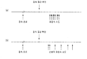
- FIG. 7 is a view for explaining the operation and effect according to the present invention.
- the push service device and the client are selectively used by using the auxiliary device of the push service device instead of immediately accessing the client. Two embodiments of attempting to connect are described.
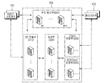
- FIG. 2 is a diagram illustrating a network configuration of a push service providing system according to an exemplary embodiment of the present invention.
- the push service providing system 100 includes a plurality of service providing apparatuses 100-1 to 100 -N: 100, a push service apparatus 300, and a plurality of clients 400-1 to 400.
- -K 400, and shows a structure in which a plurality of service providing apparatuses 100 and a plurality of clients 400 are connected through a central push service apparatus 300.
- the plurality of clients 400 may be connected to the communication network 200, and may include, for example, a PC, a notebook, a smartphone, a PDA, a notebook, a navigation, a PMP, an electronic dictionary, an MP3, and the like.
- the plurality of clients 400 are equipped with a client application for accessing the communication network 200 and transmitting and receiving predetermined data (particularly, push messages, push notifications, etc.).
- the plurality of service providing apparatuses 100 refer to a server or a terminal for providing a service by transmitting a push message to the plurality of clients 400.
- the push service device 300 basically collects push messages transmitted from the plurality of service providing devices 100 and delivers them to the corresponding client 400.
- the push service device 300 manages the interconnection of the service providing device 100 and the client 400 between the plurality of service providing devices 100 and the plurality of clients 400, and provides a plurality of services upon connection.
- the bias of the device 100 and the plurality of clients 400 are distributed according to the internal load.
- the push service device 300 processes to provide a push message transmitted from the service providing device 100 to the client 400.
- the push service device 300 is independently implemented for each function, that is, the service provider 100 and the client 400 interworking function, the function of distributing the load at the time of interworking, the function of processing push messages, etc. By separating and implementing the in-device, when the service providing apparatus 100 and the client 400 increase, the push service apparatus 300 may also be individually extended for each function.
- FIG. 3 is a detailed configuration diagram illustrating a push service device according to an embodiment of the present invention.
- the push service device 300 includes an SP interlocking unit 310, a control unit 320, a client interlocking unit 330, a load balancer 340, and an auxiliary client interlocking unit 350.
- the SP interlocking unit 310 is connected to the plurality of service providing apparatuses 100 and receives a push message to be transmitted to the client 400 from the plurality of service providing apparatuses 100.
- the push message includes new information or update information, event information, and the like.
- the client interworking unit 330 connects with the plurality of clients 400 and transmits a push message received from the SP interlocking unit 310 to the plurality of clients 400.
- the auxiliary client interlocking unit 350 is a secondary device of the client interlocking unit 330 and backs up the setting information of the client interlocking unit 330 in the event of a failure of the client interlocking unit 330 and performs the function of the client interlocking unit 330 which has failed. Do as it is.
- the setting information of the client interworking unit 330 includes mapping information between the client and the controller 320, connection request processing information from the client, information for routing a push message received from the controller 320 to the corresponding client, and the like.
- the SP interlocking unit 310 and the client interlocking unit 330 may be provided in plural numbers according to the number of connection of the service providing apparatus 100 or the client 400 connected to each of the interlocking units 310 and 330.
- each linking unit (310, 330) is the number of terminals that can be accommodated can be expanded based on this.
- each SP interlocking unit 310 and the client interlocking unit 330 provides its state information to the load balancer 340 at regular intervals.
- the state information includes the number of subscribers (or the number of connections) connected to the SP interworking unit 310 and the client interworking unit 330, data throughput (Transaction Per Seconds (TPS)), and the like.
- the load balancer 340 receives its own state information from each SP linkage unit 310 or client linkage unit 330, calculates load information of each linkage unit, and stores the calculated load information in a table.
- the load balancer 340 may refer to load information of a pre-stored interlocking unit when the access request is received from the plurality of service providing apparatuses 100 or the plurality of clients 400, and may connect the interlocking units to the service providing apparatus or the client. Assign. Therefore, the load balancer 340 plays a role of distributing the load of each of the linking units 310 and 330.
- the controller 320 manages the plurality of SP interlocking units 310 and the client interlocking unit 330, and in particular, manages routing information for the client interlocking unit 330 accessible by each client.
- the client interlocking unit 330 that can be accessed for each client refers to a client interlocking unit in which the client maintains a connection state, and may include a client interlocking unit allocated through the load balancer 340.
- the control unit 320 when receiving the push message from the SP interlocking unit 310, the control unit 320 extracts the client interlocking unit 330 accessible by the corresponding client with the client information included in the push message, and extracts the extracted client interlocking unit 330. Send a push message.
- the client interlocking unit 330 when a failure occurs in the client interlocking unit 330, the client interlocking unit 330 is abnormally terminated in connection with the client 400 and cannot transmit a push message (1).
- control unit 320 backs up the setting information of the client interlocking unit 330 to the auxiliary client interlocking unit 350 (2), and the auxiliary client interlocking unit 350 based on the backed up setting information. ) And selectively sends a push message (3).
- the selective connection between the auxiliary client interlocking unit 350 and the client 400 may be made by the auxiliary client interlocking unit 350 or the client 400.
- the auxiliary client interworking unit 350 transmits the received push message. Attempt to connect to client 400. This method is one method by which the connection attempt is made by the auxiliary client interworking unit 350.
- the keep alive time is used. That is, if a keep-alive time arrives after the client interworking unit 330 and the client 400 abnormally terminate, the client 400 transmits a keep-alive message to the auxiliary client interlocking unit 350 to assist the client. Attempt to connect the client interlocking unit 350 and the client 400.
- a keep-alive message is a message sent and received to inform the status of activity between two or more devices.
- Keep Alive messages are sent periodically at preset keep-alive times such as 60 seconds, 30 minutes, and 60 minutes.
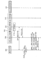
- FIG. 5 is a flowchart illustrating a push service providing method for reducing network load according to an embodiment of the present invention
- FIG. 6 is a flowchart illustrating a push service providing method for reducing network load according to another embodiment of the present invention.
- the client linkage unit 330 copies and backs up the setting information of the client linkage unit 330 to the auxiliary client linkage unit 350 additionally configured in the push service device 300 under the control of the control unit 320 of FIG. 3. S220). Since the auxiliary client interlocking unit 350 performs the same function of the client interlocking unit 330 instead of the client interlocking unit 330.
- the SP interlocking unit 310 transmits a push message transmission request to the auxiliary client interlocking unit 350 through the control unit 320 of FIG. 3 (S230), and transmits the push message to the corresponding service providing apparatus 100. Deliver the response message (S240).
- the secondary client interworking unit 350 of the push service device 300 attempts to connect with the client 400 by transmitting a text message for reconnection to the client 400 to transmit the push message (S250).
- the text message for reconnection may be in the form of a short message or transmitted in another specific message format to provide a bypass path for resuming connection with the client 400.
- the push service device 300 if the push service device 300 has a push message to be transmitted to the client after the connection with the client is terminated, the push service device 300 knows that the connection with the corresponding client is disconnected, and the auxiliary client interworking unit 350 corresponds to the corresponding client. Attempt to reconnect to the client. As a result, instantaneous network load can be prevented by reconnecting immediately upon connection termination.
- the client linkage unit 330 copies and backs up the setting information of the client linkage unit 330 to the auxiliary client linkage unit 350 additionally configured in the push service device 300 under the control of the control unit 320 of FIG. 3. S120). Since the auxiliary client interlocking unit 350 performs the same function of the client interlocking unit 330 instead of the client interlocking unit 330.
- the client 400 checks whether it is a keep-alive time (S130), and when the keep-alive time comes, the client 400 does not immediately recognize that the connection with the client interworking unit 330 is disconnected.
- the client interworking unit 330 requests the keep-alive message but does not receive a response to the request for the keep-alive message (S140).
- the client 400 If the client 400 does not receive a response to the request for a keep-alive message from the client interlocking unit 330, the client 400 recognizes that the connection with the client interlocking unit 330 is lost, and registers the register as the auxiliary client interlocking unit 350. After establishing a session by sending a message to the secondary client interworking unit 350 requests a keep-alive message (S150).
- the client 400 receives a response to the keep-alive message request from the secondary client interworking unit 350 (S160) and connects to the secondary client interworking unit 350 through this process (S170).
- the present invention determines that the connection between the push service device and the client is abnormally terminated and disconnected from the push service device or the client, as shown in FIG.
- the push service device or client selectively attempts to connect depending on whether a push message is present or keep alive time.
- the push service device receives a push message before the keep-alive time after confirming the disconnection, it attempts to connect with the client regardless of the keep-alive time, and conversely, if the keep-alive time arrives after confirming the disconnection, Whether or not a push message is received, the client attempts to connect first.
- the present invention provides a push received from the service providing device through a push service device.
- the connection with the client is terminated due to a failure of the push service device, the network load due to the connection attempt is reduced by selectively attempting to connect when necessary.
- the invention is useful as it is industrially available because the possibility of construction and sales of the applied server as well as the use of related technology is not only sufficient for the use of related technologies, but also practically clearly implemented. to be.
Landscapes
- Engineering & Computer Science (AREA)
- Computer Networks & Wireless Communication (AREA)
- Signal Processing (AREA)
- Computer Hardware Design (AREA)
- Theoretical Computer Science (AREA)
- Software Systems (AREA)
- Physics & Mathematics (AREA)
- General Engineering & Computer Science (AREA)
- General Physics & Mathematics (AREA)
- Computer And Data Communications (AREA)
Abstract
본 발명은 푸시 서비스 제공 시스템 및 방법을 개시한다. 즉, 서비스 제공 장치가 제공하는 푸시 메시지를 수신하여 푸시 서비스를 제공하는 클라이언트; 및 상기 서비스 제공 장치로부터 제공되는 상기 푸시 메시지를 상기 클라이언트에게 전달하는 푸시 서비스 장치를 포함하며, 상기 클라이언트와 상기 푸시 서비스 장치간 접속이 비정상적으로 종료될 경우, 소정 기준에 따라 상호간 재접속을 시도함으로써, 재접속 시도에 따른 망 부하를 감소시키는 효과가 있다.
Description
본 발명은 푸시(push) 서비스 제공 시스템 및 방법에 관한 것으로서, 더욱 상세하게는 푸시 서비스 장치를 통해 서비스 제공 장치로부터 제공되는 푸시 메시지를 클라이언트에게 전달함에 있어서, 푸시 서비스 장치의 장애로 클라이언트와의 접속이 해지될 경우, 푸시 서비스 장치 또는 클라이언트에서 선별적으로 재접속을 시도하도록 하는 푸시 서비스 제공 시스템 및 방법에 관한 것이다.
스마트 폰(smart phone)이 보급되고 스마트 폰 환경으로 인해 다양한 응용 프로그램(Application)이 등장함에 따라 무선 자원의 사용량이 크게 증가하고 있다. 특히, IM(Instant Messaging), 웹(Web), 위젯(Widget) 서비스와 같이 망으로부터 실시간 푸시 메시지 혹은 푸시 알림(Push Notification) 등을 받기 위해 항시 접속되어 있는 형태(Always-On 형태)의 응용 프로그램이 현재 급속도로 증가하고 있다. Always-On 형태의 응용 프로그램은 저마다 서비스 제공자와 연결을 유지하면서 푸시 서비스를 받도록 준비하고 있기 때문에 과다한 트래픽을 유발하고, 배터리 소모를 빠르게 하는 문제점이 있다.
이러한 문제점을 해결하기 위해, 서비스 제공자와 클라이언트가 직접적으로 연결되지 않고, 클라이언트(Client) 내에 구축된 데몬(Daemon)을 통해 푸시 서버와 연결을 유지하고 서비스 제공자(Service Provider)가 푸시 메시지 혹은 푸시 알림을 전송하면 중앙의 푸시 서버가 전달 받아 해당 클라이언트로 전송하는 방식을 채택하고 있다.
도 1은 종래 푸시 서비스 제공 시스템의 구성을 나타낸 도면이다.
종래 기술에 따르면, 다수의 서비스 제공자(10)와 다수의 단말(40) 사이에 게이트웨이(20)와 캐리어(30)가 구축되어 다수의 단말(40)내 설치된 응용 프로그램이 서비스 제공자(10)와 개별적으로 접속할 필요없이 캐리어(30) 및 게이트웨이(20)와 접속하여 서비스 제공자(10)가 연결되는 구조를 보여주고 있다.
게이트웨이(20)는 다수의 서비스 제공자(10)와 접속하기 위한 중계 장치이고, 캐리어(30)는 다수의 단말(40)과 접속하기 위한 장치로, 서비스 제공자(10)와 단말(40)의 증가에 따라 확장이 가능한 구조이다.
그런데, 도 1에 따른 종래 기술은 존(zone) 기반으로 단말(40)을 관리하기 때문에 캐리어(30)와 연동 시 단말(40)이 미리 설정된 정보에 따라 정해진 캐리어(30)에 할당하도록 되어 있다. 이러한 방식은 처리 속도가 빠르지만, 동일 존 내에 단말(40)이 급증하게 되면 하나의 캐리어(30)에서 수용해야 하는 단말(40)이 편중되어 부하가 걸리기 쉽다.
특히, 캐리어(30)의 장애로 단말(40)과의 접속이 비정상적으로 종료된 경우 캐리어(30)와 단말(40)간 접속을 시도하게 된다. 이러한 접속 시도는 캐리어(30) 또는 단말(40)에 의해 동시에 수행되므로 캐리어(30) 또는 단말(40)의 수가 증가할수록 망의 순간적인 부하를 유발한다.
따라서, 푸시 서비스를 이용하는 단말(클라이언트) 및 서비스 제공자가 증가하는 경우 서버가 가지는 부하를 얼만큼 효과적으로 분산할 것인가가 주요한 이슈로 대두되고 있다. 이에 따라 서비스 제공자와 단말이 푸시 서버와 접속할 때 발생하는 부하를 분산하기 위한 방안이 필요하다.
특히, 본 발명에서는 푸시 서버와 단말간 비정상적인 접속 종료로 인해 발생하는 망 부하를 분산하기 위한 방안을 개시한다.
본 발명은 상기한 사정을 감안하여 창출된 것으로서, 본 발명에서 도달하고자 하는 목적은, 클라이언트 장치와의 접속을 수행하는 푸시 서비스 장치의 장애 발생으로 인해 클라이언트와의 접속이 해지될 경우, 푸시 서비스 장치 또는 클라이언트에서 선별적으로 재접속을 시도함으로써, 푸시 서비스 장치와 클라이언트간 재접속 시도에 따른 망 부하를 감소시키기 위한 푸시 서비스 제공 시스템 및 방법을 제공하는데 있다.
상기 목적을 달성하기 위한 본 발명의 제 1 관점에 따른 푸시 서비스 제공 시스템은 서비스 제공 장치가 제공하는 푸시 메시지를 수신하여 푸시 서비스를 제공하는 클라이언트; 및 상기 서비스 제공 장치로부터 제공되는 상기 푸시 메시지를 상기 클라이언트에게 전달하는 푸시 서비스 장치를 포함하며, 상기 클라이언트 또는 상기 푸시 서비스 장치는, 상기 클라이언트와 상기 푸시 서비스 장치간 접속이 비정상적으로 종료될 경우, 소정 기준에 따라 상호간 재접속을 시도하는 것을 특징으로 한다.
바람직하게는, 상기 소정 기준은, 상기 푸시 서비스 장치에서 상기 클라이언트에 전송할 신규 푸시 메시지가 존재하거나, 상기 클라이언트에서 상기 푸시 서비스 장치와의 연결 활성화 상태를 확인하기 위해 지정된 킵 얼라이브 타임인 경우에 해당하는 것을 특징으로 한다.
상기 목적을 달성하기 위한 본 발명의 제 2 관점에 따른 푸시 서비스 장치는, 서비스 제공 장치와 접속하기 위한 SP(Service Provider) 연동부; 클라이언트와 접속하여 상기 SP 연동부로부터 수신한 푸시 메시지를 상기 하나 이상의 클라이언트에 전송하는 client 연동부; 및 상기 client 연동부와 상기 클라이언트간 접속이 비정상적으로 종료된 상태에서, 상기 SP 연동부로부터 상기 클라이언트에게 전송할 신규 푸시 메시지가 수신되거나 상기 클라이언트로부터 킵 얼라이브(keep-alive) 메시지가 수신될 경우, 상기 client 연동부를 통해 상기 클라이언트에 대한 재접속을 시도하는 제어부를 포함하는 것을 특징으로 한다.
바람직하게는, 상기 푸시 서비스 장치는, 상기 Client 연동부에 장애가 발생할 경우, 장애가 발생한 상기 Client 연동부의 설정 정보를 백업 받아 상기 Client 연동부의 기능을 대행하는 보조 Client 연동부를 더 포함하는 것을 특징으로 한다.
상기 목적을 달성하기 위한 본 발명의 제 3 관점에 따른 푸시 서비스 장치는, 서비스 제공 장치와 접속하기 위한 SP(Service Provider) 연동부; 클라이언트와 접속하여 상기 SP 연동부로부터 수신한 푸시 메시지를 상기 클라이언트에게 전송하는 client 연동부; 상기 client 연동부로부터 설정 정보를 백업하여 상기 client 연동부의 기능을 대행하는 보조 client 연동부; 및 상기 client 연동부의 장애 발생으로 상기 client 연동부와 상기 하나 이상의 클라이언트간 접속이 비정상적으로 종료될 경우, 장애가 발생한 상기 client 연동부의 설정 정보를 상기 보조 client 연동부로 백업시키는 제어부를 포함하며, 상기 보조 client 연동부는, 상기 client 연동부로부터 설정 정보를 백업한 상태에서, 상기 클라이언트로부터 킵 얼라이브(keep-alive) 메시지가 수신될 경우, 상기 킵 얼라이브 메시지에 대한 응답 메시지를 상기 클라이언트에게 전송하여 상기 클라이언트와의 재접속을 수행하는 것을 특징으로 한다.
바람직하게는, 상기 보조 client 연동부는, 기 설정된 킵 얼라이브 타임에 해당하는 주기마다 상기 킵 얼라이브 메시지를 수신하는 것을 특징으로 한다.
상기 목적을 달성하기 위한 본 발명의 제 4 관점에 따른 푸시 서비스 제공 방법은, 푸시 서비스 장치가 클라이언트와 접속하여 서비스 제공 장치로부터 제공되는 푸시 메시지를 상기 클라이언트에 전달하는 푸시메시지전달단계; 상기 푸시 서비스 장치가 장애 발생에 따라 상기 클라이언트와의 접속이 비정상적으로 종료된 것을 확인하는 비정상종료확인단계; 상기 푸시 서비스 장치가 상기 서비스 제공 장치로부터 상기 클라이언트에게 전송할 푸시 메시지를 수신하였는지 여부를 확인하거나, 상기 클라이언트가 상기 푸시 서비스 장치와의 연결 활성화 상태를 확인하기 위해 지정된 킵 얼라이브 타임인지를 확인하는 재접속판단단계; 및 상기 푸시 서비스 장치에 클라이언트에 전송할 푸시 메시지를 수신하였거나 또는 상기 킵 얼라이브 타임인 경우, 상기 푸시 서비스 장치 또는 상기 클라이언트가 상호간 재접속을 시도하는 재접속실행단계를 포함하는 것을 특징으로 한다.
바람직하게는, 상기 비정상종료확인단계는, 상기 클라이언트와의 접속이 비정상적으로 종료된 것이 확인될 경우, 상기 클라이언트와의 접속과 관련한 설정 정보를 백업하는 것을 특징으로 한다.
바람직하게는, 상기 재접속실행단계는, 상기 서비스 제공 장치로부터 상기 클라이언트에게 전송할 푸시 메시지가 수신될 경우, 상기 푸시 서비스 장치가 상기 백업된 설정 정보를 기초로 상기 클라이언트에 재접속을 위한 메시지를 전송하여 상기 클라이언트에 대한 재접속을 수행하는 것을 특징으로 한다.
바람직하게는, 상기 재접속실행단계는, 상기 킵 얼라이브 타임인 경우, 상기 클라이언트가 킵 얼라이브 메시지를 상기 백업된 설정 정보를 갖는 상기 푸시 서비스 장치에 전송하고, 상기 전송된 킵 얼라이브 메시지에 대한 응답 메시지를 기초로 상기 푸시 서비스 장치에 대한 재접속을 수행하는 것을 특징으로 한다.
이에, 본 발명에 따른 망 부하 감소를 위한 푸시 서비스 제공 시스템 및 방법에 의하면, 클라이언트 장치와의 접속을 수행하는 푸시 서비스 장치의 장애 발생으로 인해 클라이언트와의 접속이 해지될 경우, 푸시 서비스 장치 또는 클라이언트에서 선별적으로 재접속을 시도함으로써, 푸시 서비스 장치와 클라이언트간 재접속 시도에 따른 망 부하를 감소시키는 효과가 있다.
도 1은 종래 푸시 서비스 제공 시스템의 구성을 나타낸 도면이다.
도 2는 본 발명의 실시예에 따른 푸시 서비스 제공 시스템의 네트워크 구성을 나타낸 도면이다.
도 3은 본 발명의 실시예에 따른 푸시 서비스 장치의 세부 구성도이다.
도 4는 본 발명의 실시예에 따른 푸시 서비스 장치와 클라이언트간 접속 설정 구성을 나타낸 도면이다.
도 5는 본 발명의 일 실시 예에 따른 망 부하 감소를 위한 푸시 서비스 제공 방법을 나타낸 흐름도이다.
도 6은 본 발명의 다른 실시 예에 따른 망 부하 감소를 위한 푸시 서비스 제공 방법을 나타낸 흐름도이다.
도 7은 본 발명에 따른 작용 효과를 설명하기 위한 도면이다.
이하, 첨부된 도면을 참조하여 본 발명에 따른 실시 예를 상세하게 설명한다. 본 발명의 구성 및 그에 따른 작용 효과는 이하의 상세한 설명을 통해 명확하게 이해될 것이다. 본 발명의 상세한 설명에 앞서, 동일한 구성요소에 대해서는 다른 도면 상에 표시되더라도 가능한 동일한 부호로 표시하며, 공지된 구성에 대해서는 본 발명의 요지를 흐릴 수 있다고 판단되는 경우 구체적인 설명은 생략하기로 함에 유의한다.
본 발명은 푸시 서비스 장치의 장애 발생으로 푸시 서비스 장치와 클라이언트간 접속이 비정상적으로 종료된 경우 바로 클라이언트와의 접속을 수행하지 않고 푸시 서비스 장치의 보조 장치를 이용하여 선별적으로 푸시 서비스 장치와 클라이언트간 접속을 시도하는 두 가지 실시 예에 대하여 개시한다.
도 2는 본 발명의 실시예에 따른 푸시 서비스 제공 시스템의 네트워크 구성을 나타낸 도면이다.
도시된 바와 같이 본 발명에 따른 푸시 서비스 제공 시스템(100)은 다수의 서비스 제공 장치(100-1 내지 100-N: 100)와, 푸시 서비스 장치(300) 및 다수의 클라이언트(400-1 내지 400-K: 400)로 구성되어, 중앙의 푸시 서비스 장치(300)를 매개로 다수의 서비스 제공 장치(100)와 다수의 클라이언트(400)의 접속이 이루어지는 구조를 보여주고 있다.
다수의 클라이언트(400)는 통신망(200)에 접속 가능한 단말로서, 예컨대 PC, 노트북, 스마트 폰, PDA, 노트북, 네비게이션, PMP, 전자사전, MP3 등을 포함할 수 있다. 다수의 클라이언트(400)는 통신망(200)에 접속하여 소정의 데이터(특히 푸시 메시지, 푸시 알림 등)를 송수신하는 클라이언트 응용 프로그램(application)을 탑재한다.
다수의 서비스 제공 장치(100)는 다수의 클라이언트(400)로 푸시 메시지를 송신하여 서비스를 제공하는 서버 또는 단말을 의미한다.
푸시 서비스 장치(300)는 기본적으로 다수의 서비스 제공 장치(100)로부터 전송하는 푸시 메시지를 취합하여 해당 클라이언트(400)로 전달한다.
이때, 푸시 서비스 장치(300)는 다수의 서비스 제공 장치(100) 및 다수의 클라이언트(400) 사이에서 서비스 제공 장치(100) 및 클라이언트(400)의 상호 접속을 관리하고, 접속 시 다수의 서비스 제공 장치(100) 및 다수의 클라이언트(400)의 편중을 내부 부하에 따라 분산시킨다. 또한, 푸시 서비스 장치(300)는 서비스 제공 장치(100)에서 전송하는 푸시 메시지를 해당 클라이언트(400)로 제공하도록 처리한다.
이러한 푸시 서비스 장치(300)는 각 기능별로 독립적으로 구현되어 즉, 서비스 제공자(100)와 클라이언트(400)간 연동 기능과, 연동시 부하를 분산시키는 기능, 푸시 메시지를 처리하는 기능 등을 각 독립적인 장치로 분리 구현함으로써, 서비스 제공 장치(100)와 클라이언트(400)가 증가하게 되면 푸시 서비스 장치(300) 또한 각 기능별로 개별 확장이 가능하다.
도 3은 본 발명의 실시예에 따른 푸시 서비스 장치를 나타낸 세부 구성도이다.
본 발명에 따른 푸시 서비스 장치(300)는 SP 연동부(310), 제어부(320), client 연동부(330), 부하 분산부(340), 보조 client 연동부(350)를 포함한다.
SP 연동부(310)는 다수의 서비스 제공 장치(100)와 접속하여 다수의 서비스 제공 장치(100)로부터 클라이언트(400)에 전송할 푸시 메시지를 수신한다. 여기서, 푸시 메시지는 신규 정보 또는 갱신 정보, 이벤트 정보 등을 포함한다.
client 연동부(330)는 다수의 클라이언트(400)와 접속하여 SP 연동부(310)로부터 수신한 푸시 메시지를 다수의 클라이언트(400)로 전송한다.
보조 client 연동부(350)는 client 연동부(330)의 보조 장치로서 client 연동부(330)의 장애시 client 연동부(330)의 설정 정보를 백업하고 장애가 발생한 client 연동부(330)의 기능을 그대로 수행한다. client 연동부(330)의 설정 정보란 클라이언트와 제어부(320)간 매핑 정보, 클라이언트로부터 접속 요청 처리 정보, 제어부(320)에서 받은 푸시 메시지를 해당 클라이언트에게 라우팅하는 정보 등을 포함한다.
이때, SP 연동부(310) 및 client 연동부(330)는 각 연동부(310, 330)에 접속하는 서비스 제공 장치(100) 또는 클라이언트(400)의 접속 수에 따라 복수 개로 구비할 수 있다. 일반적으로 각 연동부(310, 330)는 수용 가능한 단말의 수가 정해져 있어서 이를 기준으로 증설이 가능하다.
또한, 각 SP 연동부(310) 및 client 연동부(330)는 일정 주기마다 자신의 상태 정보를 부하 분산부(340)로 제공한다. 상태 정보는 SP 연동부(310) 및 client 연동부(330)에 접속되어 있는 가입자 수(또는 접속 수라 칭함), 데이터 처리량(Transaction Per Seconds: TPS) 등을 포함한다.
그러면 부하 분산부(340)는 각 SP 연동부(310) 또는 client 연동부(330)로부터 자신의 상태 정보를 수신하여 각 연동부의 부하 정보를 산출하고, 산출한 부하 정보를 테이블화하여 저장한다.
또한, 부하 분산부(340)는 다수의 서비스 제공 장치(100) 또는 다수의 클라이언트(400)로부터 접속 요청이 있으면 기 저장한 연동부의 부하 정보를 참조하여 접속 가능한 각 연동부를 서비스 제공 장치 또는 클라이언트에 할당한다. 따라서, 부하 분산부(340)는 각 연동부(310, 330)의 부하를 분산시키는 역할을 담당한다.
제어부(320)는 다수의 SP 연동부(310) 및 client 연동부(330)를 관리하며 특히 각 클라이언트별로 접속 가능한 client 연동부(330)에 대한 라우팅 정보를 관리한다. 여기서, 각 클라이언트별로 접속 가능한 Client 연동부(330)는 클라이언트가 접속 상태를 유지하고 있는 client 연동부를 의미하는 것으로, 부하 분산부(340)를 통해 할당받은 client 연동부를 포함할 수 있다.
따라서, 제어부(320)는 SP 연동부(310)로부터 푸시 메시지를 수신하면 푸시 메시지에 포함되어 있는 클라이언트 정보를 가지고 해당 클라이언트가 접속 가능한 client 연동부(330)를 추출하고, 추출한 client 연동부(330)로 푸시 메시지를 전송한다.
이때, 도 4에 도시한 바와 같이 client 연동부(330)에서 장애가 발생하면 client 연동부(330)는 클라이언트(400)와의 접속이 비정상적으로 종료되고 푸시 메시지를 전송하지 못하게 된다(①).
이 경우, 제어부(320)가 client 연동부(330)의 설정 정보를 보조 client 연동부(350)로 백업하고(②), 보조 client 연동부(350)는 백업 받은 설정 정보를 기초로 클라이언트(400)와 선별적으로 접속하여 푸시 메시지를 전송한다(③). 이때 보조 client 연동부(350)와 클라이언트(400)와의 선별적 접속은 보조 client 연동부(350) 또는 클라이언트(400)에 의해 이루어질 수 있다.
예를 들어, client 연동부(330)와 클라이언트(400)가 비정상적으로 종료한 이후 푸시 서비스 장치가 클라이언트에게 전송할 푸시 메시지를 수신하게 되면 보조 client 연동부(350)가 수신된 푸시 메시지를 전송하기 위해 클라이언트(400)로 접속을 시도한다. 이러한 방법은 보조 client 연동부(350)에 의해 접속 시도가 이루어지는 하나의 방법이다.
또 다른 방법으로 클라이언트에 의해 접속 시도가 이루어지는 경우는 킵 얼라이브 타임을 이용한 것이다. 즉, client 연동부(330)와 클라이언트(400)가 비정상적으로 종료한 이후 킵 얼라이브(keep-alive) 타임이 도래하면 클라이언트(400)가 보조 client 연동부(350)로 킵 얼라이브 메시지를 전송하여 보조 client 연동부(350)와 클라이언트(400)간 접속을 시도한다.
킵 얼라이브(keep-alive) 메시지는 둘 이상의 장치간 활성 상태를 알려주기 위해 보내고 받는 메시지를 말한다. 본 발명에서는 푸시 서비스 장치의 client 연동부(330) 또는 보조 client 연동부(350)와 클라이언트(400)간에 킵 얼라이브 메시지를 서로 교환함으로써 상호 접속 상태를 확인할 수 있다. 킵 얼라이브 메시지는 60초, 30분, 60분 등 기 설정된 킵 얼라이브 타임마다 주기적으로 전송한다.
이하에서는 상기의 두 가지 방법을 이용하여 푸시 서비스 장치와 클라이언트간 접속을 통해 망 부하를 방지할 수 있는 푸시 서비스 제공 방법에 대하여 구체적으로 설명한다.
도 5는 본 발명의 일 실시 예에 따른 망 부하 감소를 위한 푸시 서비스 제공 방법을 나타낸 흐름도이고, 도 6은 본 발명의 다른 실시 예에 따른 망 부하 감소를 위한 푸시 서비스 제공 방법을 나타낸 흐름도이다.
먼저 도 5를 참조하여 푸시 서비스 장치와 클라이언트간 접속을 시도하여 푸시 서비스를 제공하는 방법을 설명한다.
푸시 서비스 장치(300) 내 client 연동부(330)에 장애가 발생하면(S200), client 연동부(330)와 접속하고 있던 클라이언트(400)와의 접속이 비정상적으로 종료된다(S210).
client 연동부(330)는 제어부(도 3의 320)의 제어에 따라 푸시 서비스 장치(300)에 추가 구성한 보조 client 연동부(350)에 client 연동부(330)의 설정 정보를 복사하여 백업한다(S220). 이후부터 보조 client 연동부(350)는 client 연동부(330) 대신 client 연동부(330)의 기능을 동일하게 수행한다.
이후, 푸시 서비스 장치(300)와 클라이언트(400)간 접속이 종료된 상태에서, 푸시 서비스 장치(400)의 SP 연동부(310)에 서비스 제공 장치(100)로부터 푸시 메시지의 전송 요청이 수신되면 SP 연동부(310)는 제어부(도 3의 320)를 통해 보조 client 연동부(350)로 푸시 메시지의 전송 요청을 전달하고(S230), 해당 서비스 제공 장치(100)로 푸시 메시지의 전송에 대한 응답 메시지를 전달한다(S240).
그러면, 푸시 서비스 장치(300)의 보조 client 연동부(350)는 푸시 메시지를 전송할 클라이언트(400)에 재접속을 위한 문자 메시지를 전송하여 클라이언트(400)와의 접속을 시도한다(S250). 재접속을 위한 문자 메시지는 단문 메시지(Short Message) 형태이거나 다른 특정 메시지 포맷으로 전송하여 클라이언트(400)와의 접속을 재개하기 위한 우회 경로를 제공한다.
따라서, 푸시 서비스 장치(300)는 클라이언트와 접속이 종료된 이후 클라이언트에게 전송할 푸시 메시지가 존재할 경우 보조 client 연동부(350)가 해당 클라이언트와 접속이 끊어짐을 알게 되고 보조 client 연동부(350)가 해당 클라이언트에 재접속을 시도한다. 이로써 접속 종료시 바로 재접속을 수행함에 따른 순간적인 망 부하를 막을 수 있다.
다음으로 도 6을 참조하면, 도 5와 마찬가지로 푸시 서비스 장치(300)의 client 연동부(330)에 장애가 발생하면(S100), client 연동부(330)와 접속하고 있던 클라이언트(400)와의 접속이 비정상적으로 종료된다(S110).
client 연동부(330)는 제어부(도 3의 320)의 제어에 따라 푸시 서비스 장치(300)에 추가 구성한 보조 client 연동부(350)에 client 연동부(330)의 설정 정보를 복사하여 백업한다(S120). 이후부터 보조 client 연동부(350)는 client 연동부(330) 대신 client 연동부(330)의 기능을 동일하게 수행한다.
이후, 클라이언트(400)는 킵 얼라이브 타임(keep-alive time)인지를 체크하고(S130), 킵 얼라이브 타임이 되면 클라이언트(400)는 client 연동부(330)와 접속이 끊어졌음을 바로 인지하지 못하여 client 연동부(330)로 킵 얼라이브 메시지를 요청하지만 킵 얼라이브 메시지의 요청에 대한 응답을 받지 못한다(S140).
클라이언트(400)는 client 연동부(330)로부터 킵 얼라이브 메시지의 요청에 대한 응답이 수신되지 않으면 client 연동부(330)와 접속이 끊어짐을 인지하게 되고, 보조 Client 연동부(350)로 레지스터(Register) 메시지를 보내어 세션을 수립한 후 보조 client 연동부(350)로 킵 얼라이브 메시지를 요청한다(S150).
이후, 클라이언트(400)는 보조 client 연동부(350)로부터 킵 얼라이브 메시지 요청에 대한 응답을 수신하고(S160) 이러한 과정을 통해 보조 client 연동부(350)와 접속한다(S170).
이와 같이 도 5 및 도 6의 방법을 통해 본 발명은 도 7의 (b)에 도시한 바와 같이 푸시 서비스 장치와 클라리언트간 접속이 비정상적으로 종료되고 푸시 서비스 장치 또는 클라이언트에서 접속 끊김을 확인하게 되면, 푸시 서비스 장치 또는 클라이언트에서 푸시 메시지의 존재 여부 또는 킵 얼라이브 타임 여부에 따라 선별적으로 접속을 시도한다.
예를 들어, 접속 끊어짐을 확인한 후 푸시 서비스 장치가 킵 얼라이브 타임보다 푸시 메시지를 먼저 수신하게 되면 킵 얼라이브 타임과 상관없이 클라이언트와 접속을 시도하고, 이와 반대로 접속 끊어짐을 확인한 후 킵 얼라이브 타임이 도래하면 푸시 메지시의 수신 여부와 상관없이 클라이언트가 먼저 접속을 시도한다.
따라서, (a)와 같이 접속 종료시 바로 클라이언트와 푸시 서비스 장치간 재 접속을 시도함에 따라 발생하는 순간적인 망 부하를 막을 수 있다.
이상의 설명은 본 발명을 예시적으로 설명한 것에 불과하며, 본 발명이 속하는 기술 분야에서 통상의 지식을 가진 자에 의해 본 발명의 기술적 사상에서 벗어나지 않는 범위에서 다양한 변형이 가능할 것이다. 따라서 본 발명의 명세서에 개시된 실시 예들은 본 발명을 한정하는 것이 아니다. 본 발명의 범위는 아래의 특허청구범위에 의해 해석되어야 하며, 그와 균등한 범위 내에 있는 모든 기술도 본 발명의 범위에 포함되는 것으로 해석해야 할 것이다.
종래 푸시 서비스를 제공하는 시스템은 서비스 제공자 및 클라이언트의 접속 수가 급증하게 되면 푸시 서버에서 수용해야 하는 단말이 편중되어 과다한 부하가 발생하였으나, 본 발명은 푸시 서비스 장치를 매개로 서비스 제공 장치로부터 수신한 푸시 메시지를 클라이언트에게 제공할 때 푸시 서비스 장치의 장애로 클라이언트와의 접속이 해지되면 바로 접속을 시도하지 않고 필요할 때 선별적으로 접속을 시도하여 접속 시도로 인한 망 부하를 감소시킨 효과가 있다. 이러한 점에서 종래 푸시 서버의 한계를 뛰어 넘음에 따라 관련 기술에 대한 이용만이 아닌 적용되는 서버의 구축 및 영업의 가능성이 충분할 뿐만 아니라 현실적으로 명백하게 실시할 수 있는 정도이므로 산업상 이용 가능성이 있는 유용한 발명이다.
Claims (10)
- 서비스 제공 장치가 제공하는 푸시 메시지를 수신하여 푸시 서비스를 제공하는 클라이언트; 및상기 서비스 제공 장치로부터 제공되는 상기 푸시 메시지를 상기 클라이언트에게 전달하는 푸시 서비스 장치를 포함하며,상기 클라이언트 또는 상기 푸시 서비스 장치는,상기 클라이언트와 상기 푸시 서비스 장치간 접속이 비정상적으로 종료될 경우, 소정 기준에 따라 상호간 재접속을 시도하는 것을 특징으로 하는 푸시 서비스 제공 시스템.
- 제 1 항에 있어서,상기 소정 기준은,상기 푸시 서비스 장치에서 상기 클라이언트에 전송할 신규 푸시 메시지가 존재하거나, 상기 클라이언트에서 상기 푸시 서비스 장치와의 연결 활성화 상태를 확인하기 위해 지정된 킵 얼라이브 타임인 경우에 해당하는 것을 특징으로 하는 푸시 서비스 제공 시스템.
- 서비스 제공 장치와 접속하기 위한 SP(Service Provider) 연동부;클라이언트와 접속하여 상기 SP 연동부로부터 수신한 푸시 메시지를 상기 하나 이상의 클라이언트에 전송하는 client 연동부; 및상기 client 연동부와 상기 클라이언트간 접속이 비정상적으로 종료된 상태에서, 상기 SP 연동부로부터 상기 클라이언트에게 전송할 신규 푸시 메시지가 수신되거나 상기 클라이언트로부터 킵 얼라이브(keep-alive) 메시지가 수신될 경우, 상기 client 연동부를 통해 상기 클라이언트에 대한 재접속을 시도하는 제어부를 포함하는 것을 특징으로 하는 푸시 서비스 장치.
- 제 3 항에 있어서,상기 푸시 서비스 장치는,상기 Client 연동부에 장애가 발생할 경우, 장애가 발생한 상기 Client 연동부의 설정 정보를 백업 받아 상기 Client 연동부의 기능을 대행하는 보조 Client 연동부를 더 포함하는 것을 특징으로 하는 푸시 서비스 장치.
- 서비스 제공 장치와 접속하기 위한 SP(Service Provider) 연동부;클라이언트와 접속하여 상기 SP 연동부로부터 수신한 푸시 메시지를 상기 클라이언트에게 전송하는 client 연동부;상기 client 연동부로부터 설정 정보를 백업하여 상기 client 연동부의 기능을 대행하는 보조 client 연동부; 및상기 client 연동부의 장애 발생으로 상기 client 연동부와 상기 하나 이상의 클라이언트간 접속이 비정상적으로 종료될 경우, 장애가 발생한 상기 client 연동부의 설정 정보를 상기 보조 client 연동부로 백업시키는 제어부를 포함하며,상기 보조 client 연동부는,상기 client 연동부로부터 설정 정보를 백업한 상태에서, 상기 클라이언트로부터 킵 얼라이브(keep-alive) 메시지가 수신될 경우, 상기 킵 얼라이브 메시지에 대한 응답 메시지를 상기 클라이언트에게 전송하여 상기 클라이언트와의 재접속을 수행하는 것을 특징으로 하는 푸시 서비스 장치.
- 제 5 항에 있어서,상기 보조 client 연동부는,기 설정된 킵 얼라이브 타임에 해당하는 주기마다 상기 킵 얼라이브 메시지를 수신하는 것을 특징으로 하는 푸시 서비스 장치.
- 푸시 서비스 장치가 클라이언트와 접속하여 서비스 제공 장치로부터 제공되는 푸시 메시지를 상기 클라이언트에 전달하는 푸시메시지전달단계;상기 푸시 서비스 장치가 장애 발생에 따라 상기 클라이언트와의 접속이 비정상적으로 종료된 것을 확인하는 비정상종료확인단계;상기 푸시 서비스 장치가 상기 서비스 제공 장치로부터 상기 클라이언트에게 전송할 푸시 메시지를 수신하였는지 여부를 확인하거나, 상기 클라이언트가 상기 푸시 서비스 장치와의 연결 활성화 상태를 확인하기 위해 지정된 킵 얼라이브 타임인지를 확인하는 재접속판단단계; 및상기 푸시 서비스 장치에 클라이언트에 전송할 푸시 메시지를 수신하였거나 또는 상기 킵 얼라이브 타임인 경우, 상기 푸시 서비스 장치 또는 상기 클라이언트가 상호간 재접속을 시도하는 재접속실행단계를 포함하는 것을 특징으로 하는 푸시 서비스 제공 방법.
- 제 7 항에 있어서,상기 비정상종료확인단계는,상기 클라이언트와의 접속이 비정상적으로 종료된 것이 확인될 경우, 상기 클라이언트와의 접속과 관련한 설정 정보를 백업하는 것을 특징으로 하는 푸시 서비스 제공 방법.
- 제 8 항에 있어서,상기 재접속실행단계는상기 서비스 제공 장치로부터 상기 클라이언트에게 전송할 푸시 메시지가 수신될 경우, 상기 푸시 서비스 장치가 상기 백업된 설정 정보를 기초로 상기 클라이언트에 재접속을 위한 메시지를 전송하여 상기 클라이언트에 대한 재접속을 수행하는 것을 특징으로 하는 푸시 서비스 제공 방법.
- 제 8 항에 있어서,상기 재접속실행단계는,상기 킵 얼라이브 타임인 경우, 상기 클라이언트가 킵 얼라이브 메시지를 상기 백업된 설정 정보를 갖는 상기 푸시 서비스 장치에 전송하고, 상기 전송된 킵 얼라이브 메시지에 대한 응답 메시지를 기초로 상기 푸시 서비스 장치에 대한 재접속을 수행하는 것을 특징으로 하는 푸시 서비스 제공 방법.
Priority Applications (2)
| Application Number | Priority Date | Filing Date | Title |
|---|---|---|---|
| CN201280022955.6A CN103563305B (zh) | 2011-05-16 | 2012-05-15 | 提供推送服务以减小网络负载的系统和方法 |
| US14/052,029 US9491132B2 (en) | 2011-05-16 | 2013-10-11 | System and method for providing push service for reducing network loads |
Applications Claiming Priority (2)
| Application Number | Priority Date | Filing Date | Title |
|---|---|---|---|
| KR1020110045902A KR101407597B1 (ko) | 2011-05-16 | 2011-05-16 | 망 부하 감소를 위한 푸시 서비스 제공 시스템 및 방법 |
| KR10-2011-0045902 | 2011-05-16 |
Related Child Applications (1)
| Application Number | Title | Priority Date | Filing Date |
|---|---|---|---|
| US14/052,029 Continuation US9491132B2 (en) | 2011-05-16 | 2013-10-11 | System and method for providing push service for reducing network loads |
Publications (2)
| Publication Number | Publication Date |
|---|---|
| WO2012157939A2 true WO2012157939A2 (ko) | 2012-11-22 |
| WO2012157939A3 WO2012157939A3 (ko) | 2013-01-24 |
Family
ID=47177473
Family Applications (1)
| Application Number | Title | Priority Date | Filing Date |
|---|---|---|---|
| PCT/KR2012/003793 Ceased WO2012157939A2 (ko) | 2011-05-16 | 2012-05-15 | 망 부하 감소를 위한 푸시 서비스 제공 시스템 및 방법 |
Country Status (4)
| Country | Link |
|---|---|
| US (1) | US9491132B2 (ko) |
| KR (1) | KR101407597B1 (ko) |
| CN (1) | CN103563305B (ko) |
| WO (1) | WO2012157939A2 (ko) |
Families Citing this family (3)
| Publication number | Priority date | Publication date | Assignee | Title |
|---|---|---|---|---|
| CA2918806A1 (en) * | 2015-01-22 | 2016-07-22 | Gubagoo Inc. | Systems and methods for call backup and takeover using web and mobile interfaces |
| KR102567900B1 (ko) * | 2018-10-09 | 2023-08-18 | 구글 엘엘씨 | 클라우드 저하 모드에서 지속적인 디바이스 동작 안정성을 보장하기 위한 방법 및 장치 |
| CN112398752B (zh) * | 2020-11-16 | 2022-04-26 | 广州华多网络科技有限公司 | 消息推送控制方法及其装置、设备、介质 |
Family Cites Families (16)
| Publication number | Priority date | Publication date | Assignee | Title |
|---|---|---|---|---|
| AU2001257364A1 (en) * | 2000-04-27 | 2001-11-07 | Fortress Technologies, Inc. | Network interface device having primary and backup interfaces for automatic dialbackup upon loss of a primary connection and method of using same |
| JP2003288298A (ja) * | 2002-03-27 | 2003-10-10 | Hitachi Ltd | プッシュサービス情報中継装置およびプッシュサービス情報中継方法 |
| CA2504800C (en) * | 2002-11-04 | 2011-09-20 | Research In Motion Limited | Method and system for maintaining a wireless data connection |
| US7475142B2 (en) * | 2002-12-06 | 2009-01-06 | Cisco Technology, Inc. | CIFS for scalable NAS architecture |
| US20040219925A1 (en) * | 2003-04-30 | 2004-11-04 | Motorola, Inc. | Image data transfer over a dispatch voice channel |
| US7355975B2 (en) * | 2004-04-30 | 2008-04-08 | International Business Machines Corporation | Method and apparatus for group communication with end-to-end reliability |
| US8055711B2 (en) * | 2004-10-29 | 2011-11-08 | Emc Corporation | Non-blocking commit protocol systems and methods |
| GB2420044B (en) * | 2004-11-03 | 2009-04-01 | Pedagog Ltd | Viewing system |
| CN101034996A (zh) * | 2006-03-09 | 2007-09-12 | 腾讯科技(深圳)有限公司 | 即时消息推送方法及其系统 |
| KR100695212B1 (ko) * | 2006-03-09 | 2007-03-14 | 에스케이 텔레콤주식회사 | 푸쉬 메시지를 자동 저장하는 방법 및 이동통신 단말기 |
| KR100788245B1 (ko) * | 2006-10-19 | 2007-12-27 | (주)인트로모바일 | 통합 푸시 서비스 시스템 및 제공방법 |
| CN101184019A (zh) * | 2006-11-14 | 2008-05-21 | 中兴通讯股份有限公司 | 一种向多终端动态推送业务信息的系统 |
| US7693953B2 (en) * | 2007-01-12 | 2010-04-06 | Microsoft Corporation | Providing Web services for wireless communication devices |
| US8548433B1 (en) * | 2007-06-27 | 2013-10-01 | Smith Micro Software, Inc. | Voice messaging service for network-based instant connect systems |
| US8099764B2 (en) * | 2007-12-17 | 2012-01-17 | Microsoft Corporation | Secure push and status communication between client and server |
| CN101588384A (zh) * | 2008-05-19 | 2009-11-25 | 北京亿企通信息技术有限公司 | 一种给企业用户推送信息的方法和系统 |
-
2011
- 2011-05-16 KR KR1020110045902A patent/KR101407597B1/ko active Active
-
2012
- 2012-05-15 WO PCT/KR2012/003793 patent/WO2012157939A2/ko not_active Ceased
- 2012-05-15 CN CN201280022955.6A patent/CN103563305B/zh not_active Expired - Fee Related
-
2013
- 2013-10-11 US US14/052,029 patent/US9491132B2/en active Active
Also Published As
| Publication number | Publication date |
|---|---|
| CN103563305B (zh) | 2018-10-09 |
| US20140040380A1 (en) | 2014-02-06 |
| WO2012157939A3 (ko) | 2013-01-24 |
| CN103563305A (zh) | 2014-02-05 |
| US9491132B2 (en) | 2016-11-08 |
| KR101407597B1 (ko) | 2014-06-13 |
| KR20120128031A (ko) | 2012-11-26 |
Similar Documents
| Publication | Publication Date | Title |
|---|---|---|
| WO2012157940A2 (ko) | 피드백메시지를 이용한 푸시 서비스 제공 시스템 및 방법 | |
| WO2013012184A2 (ko) | 메시지 부하 분산을 위한 푸시 서비스 제공 시스템 및 그 방법 | |
| CN105407008A (zh) | Tcp连接断线的重连方法及系统、终端及服务器 | |
| US20040001512A1 (en) | Method and apparatus for peer to peer bandwidth sharing | |
| CN102594802A (zh) | 低延迟联网的方法及系统 | |
| CN105528254A (zh) | 一种业务处理方法及装置 | |
| WO2010127625A2 (zh) | 坐席的处理方法、交换机及呼叫中心 | |
| CN108270593A (zh) | 一种双机热备份方法和系统 | |
| EP2944073A2 (en) | Method and system for the handling of redundant long poll | |
| KR101407597B1 (ko) | 망 부하 감소를 위한 푸시 서비스 제공 시스템 및 방법 | |
| KR101272077B1 (ko) | 망 부하 감소를 위한 푸시 서비스 제공 시스템 및 방법 | |
| CN110913008B (zh) | 一种数据传输方法及装置 | |
| CN102006223B (zh) | 卡间数据传输方法、装置及系统、板卡和分布式系统 | |
| KR101251630B1 (ko) | 푸쉬 서비스 제공 시스템 및 방법 | |
| WO2023277348A1 (en) | Method for connecting ue to dnn in public network integrated npn and a user equipment | |
| WO2012044050A2 (en) | Apparatus and method for saving power of usb device | |
| CN113220448B (zh) | 一种双机系统及其控制方法 | |
| WO2013105809A1 (ko) | 통신 시스템 및 그 통신 시스템에서 푸시 서비스 제공 방법 | |
| CN115604284A (zh) | 数据同步方法、设备及存储介质 | |
| JP2962062B2 (ja) | プロセッサ監視方式 | |
| CN106804054B (zh) | 一种虚拟化基站接入网络共享传输资源的方法及装置 | |
| JP3056075B2 (ja) | ネットワークパスの切断・再接続方式 | |
| KR100454678B1 (ko) | 무선 인터넷 접속장치에서 휴지상태를 고려한 호해제/과금전송방법 | |
| JPH08204704A (ja) | 通信装置 | |
| RU190237U1 (ru) | Абонентское сетевое устройство с виртуализированными сетевыми функциями |
Legal Events
| Date | Code | Title | Description |
|---|---|---|---|
| NENP | Non-entry into the national phase |
Ref country code: DE |
|
| 32PN | Ep: public notification in the ep bulletin as address of the adressee cannot be established |
Free format text: NOTING OF LOSS OF RIGHTS PURSUANT TO RULE 112(1) EPC (EPO FORM 1205 DATED 24/02/2014) |
|
| 121 | Ep: the epo has been informed by wipo that ep was designated in this application |
Ref document number: 12785234 Country of ref document: EP Kind code of ref document: A2 |
|
| 122 | Ep: pct application non-entry in european phase |
Ref document number: 12785234 Country of ref document: EP Kind code of ref document: A2 |