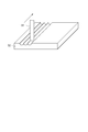
WO2012157707A1 - レンズ部品および画像表示装置 - Google Patents

レンズ部品および画像表示装置 Download PDF

Info

Publication number
WO2012157707A1
WO2012157707A1 PCT/JP2012/062666 JP2012062666W WO2012157707A1 WO 2012157707 A1 WO2012157707 A1 WO 2012157707A1 JP 2012062666 W JP2012062666 W JP 2012062666W WO 2012157707 A1 WO2012157707 A1 WO 2012157707A1
Authority
WO
WIPO (PCT)
Prior art keywords
lens
image
unit
partial
display panel
Prior art date
Legal status (The legal status is an assumption and is not a legal conclusion. Google has not performed a legal analysis and makes no representation as to the accuracy of the status listed.)
Ceased
Application number
PCT/JP2012/062666
Other languages
English (en)
French (fr)
Inventor
多久島 道子
知巳 佐野
依田 潤
雅也 西
Current Assignee (The listed assignees may be inaccurate. Google has not performed a legal analysis and makes no representation or warranty as to the accuracy of the list.)
Sumitomo Electric Fine Polymer Inc
Sumitomo Electric Industries Ltd
Original Assignee
Sumitomo Electric Fine Polymer Inc
Sumitomo Electric Industries Ltd
Priority date (The priority date is an assumption and is not a legal conclusion. Google has not performed a legal analysis and makes no representation as to the accuracy of the date listed.)
Filing date
Publication date
Application filed by Sumitomo Electric Fine Polymer Inc, Sumitomo Electric Industries Ltd filed Critical Sumitomo Electric Fine Polymer Inc
Priority to CN201280023209.9A priority Critical patent/CN103534621B/zh
Priority to KR1020137033287A priority patent/KR20140022073A/ko
Priority to KR1020157022888A priority patent/KR20150104212A/ko
Priority to US14/118,514 priority patent/US9366876B2/en
Publication of WO2012157707A1 publication Critical patent/WO2012157707A1/ja
Anticipated expiration legal-status Critical
Ceased legal-status Critical Current

Links

Images

Classifications

    • GPHYSICS
    • G02OPTICS
    • G02BOPTICAL ELEMENTS, SYSTEMS OR APPARATUS
    • G02B30/00Optical systems or apparatus for producing three-dimensional [3D] effects, e.g. stereoscopic images
    • G02B30/20Optical systems or apparatus for producing three-dimensional [3D] effects, e.g. stereoscopic images by providing first and second parallax images to an observer's left and right eyes
    • G02B30/26Optical systems or apparatus for producing three-dimensional [3D] effects, e.g. stereoscopic images by providing first and second parallax images to an observer's left and right eyes of the autostereoscopic type
    • G02B30/27Optical systems or apparatus for producing three-dimensional [3D] effects, e.g. stereoscopic images by providing first and second parallax images to an observer's left and right eyes of the autostereoscopic type involving lenticular arrays
    • GPHYSICS
    • G02OPTICS
    • G02BOPTICAL ELEMENTS, SYSTEMS OR APPARATUS
    • G02B3/00Simple or compound lenses
    • G02B3/02Simple or compound lenses with non-spherical faces
    • G02B3/06Simple or compound lenses with non-spherical faces with cylindrical or toric faces
    • GPHYSICS
    • G02OPTICS
    • G02BOPTICAL ELEMENTS, SYSTEMS OR APPARATUS
    • G02B3/00Simple or compound lenses
    • GPHYSICS
    • G02OPTICS
    • G02BOPTICAL ELEMENTS, SYSTEMS OR APPARATUS
    • G02B3/00Simple or compound lenses
    • G02B3/0006Arrays
    • G02B3/0037Arrays characterized by the distribution or form of lenses
    • GPHYSICS
    • G02OPTICS
    • G02BOPTICAL ELEMENTS, SYSTEMS OR APPARATUS
    • G02B30/00Optical systems or apparatus for producing three-dimensional [3D] effects, e.g. stereoscopic images
    • GPHYSICS
    • G02OPTICS
    • G02BOPTICAL ELEMENTS, SYSTEMS OR APPARATUS
    • G02B5/00Optical elements other than lenses
    • GPHYSICS
    • G02OPTICS
    • G02FOPTICAL DEVICES OR ARRANGEMENTS FOR THE CONTROL OF LIGHT BY MODIFICATION OF THE OPTICAL PROPERTIES OF THE MEDIA OF THE ELEMENTS INVOLVED THEREIN; NON-LINEAR OPTICS; FREQUENCY-CHANGING OF LIGHT; OPTICAL LOGIC ELEMENTS; OPTICAL ANALOGUE/DIGITAL CONVERTERS
    • G02F1/00Devices or arrangements for the control of the intensity, colour, phase, polarisation or direction of light arriving from an independent light source, e.g. switching, gating or modulating; Non-linear optics
    • G02F1/01Devices or arrangements for the control of the intensity, colour, phase, polarisation or direction of light arriving from an independent light source, e.g. switching, gating or modulating; Non-linear optics for the control of the intensity, phase, polarisation or colour 
    • G02F1/13Devices or arrangements for the control of the intensity, colour, phase, polarisation or direction of light arriving from an independent light source, e.g. switching, gating or modulating; Non-linear optics for the control of the intensity, phase, polarisation or colour  based on liquid crystals, e.g. single liquid crystal display cells
    • G02F1/133Constructional arrangements; Operation of liquid crystal cells; Circuit arrangements
    • G02F1/1333Constructional arrangements; Manufacturing methods
    • G02F1/1335Structural association of cells with optical devices, e.g. polarisers or reflectors
    • GPHYSICS
    • G03PHOTOGRAPHY; CINEMATOGRAPHY; ANALOGOUS TECHNIQUES USING WAVES OTHER THAN OPTICAL WAVES; ELECTROGRAPHY; HOLOGRAPHY
    • G03BAPPARATUS OR ARRANGEMENTS FOR TAKING PHOTOGRAPHS OR FOR PROJECTING OR VIEWING THEM; APPARATUS OR ARRANGEMENTS EMPLOYING ANALOGOUS TECHNIQUES USING WAVES OTHER THAN OPTICAL WAVES; ACCESSORIES THEREFOR
    • G03B35/00Stereoscopic photography
    • GPHYSICS
    • G03PHOTOGRAPHY; CINEMATOGRAPHY; ANALOGOUS TECHNIQUES USING WAVES OTHER THAN OPTICAL WAVES; ELECTROGRAPHY; HOLOGRAPHY
    • G03BAPPARATUS OR ARRANGEMENTS FOR TAKING PHOTOGRAPHS OR FOR PROJECTING OR VIEWING THEM; APPARATUS OR ARRANGEMENTS EMPLOYING ANALOGOUS TECHNIQUES USING WAVES OTHER THAN OPTICAL WAVES; ACCESSORIES THEREFOR
    • G03B35/00Stereoscopic photography
    • G03B35/18Stereoscopic photography by simultaneous viewing
    • G03B35/24Stereoscopic photography by simultaneous viewing using apertured or refractive resolving means on screens or between screen and eye
    • HELECTRICITY
    • H04ELECTRIC COMMUNICATION TECHNIQUE
    • H04NPICTORIAL COMMUNICATION, e.g. TELEVISION
    • H04N13/00Stereoscopic video systems; Multi-view video systems; Details thereof
    • H04N13/30Image reproducers
    • HELECTRICITY
    • H04ELECTRIC COMMUNICATION TECHNIQUE
    • H04NPICTORIAL COMMUNICATION, e.g. TELEVISION
    • H04N13/00Stereoscopic video systems; Multi-view video systems; Details thereof
    • H04N13/30Image reproducers
    • H04N13/302Image reproducers for viewing without the aid of special glasses, i.e. using autostereoscopic displays
    • H04N13/305Image reproducers for viewing without the aid of special glasses, i.e. using autostereoscopic displays using lenticular lenses, e.g. arrangements of cylindrical lenses

Definitions

  • the range in the Y direction represented by the following formula (1) is the left-eye image I L corresponding to the left eye portion pixels 22 L is
  • the right-eye image I R corresponding to the right eye portion pixels 22 R is formed in a range in the Y direction
  • Black areas I B corresponding to the shielding area 23 is formed in a range in the Y direction is represented by the following equation (3).
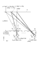
  • FIG. 5 is a diagram showing the trajectory of the light rays from the partial pixels 22 R when the lens to the display panel 20 in the first comparative example is shifted in the -Y direction.
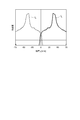
  • FIG. 6 is a diagram showing a light intensity distribution on the image plane A when the lens is shifted in the ⁇ Y direction with respect to the display panel 20 in the first comparative example.
  • Figure 7 is a diagram showing the trajectory of the light rays from the partial pixels 22 R when the shift lens in the + Y direction with respect to the display panel 20 in the first comparative example.
  • FIG. 5 is a diagram showing the trajectory of the light rays from the partial pixels 22 R when the lens to the display panel 20 in the first comparative example is shifted in the -Y direction.
  • FIG. 6 is a diagram showing a light intensity distribution on the image plane A when the lens is shifted in the ⁇ Y direction with respect to the display panel 20 in the first comparative example.
  • Figure 7 is a diagram showing the trajectory of the light rays from the partial pixels
  • FIG. 8 is a diagram showing a light intensity distribution on the image plane A when the lens is shifted in the + Y direction with respect to the display panel 20 in the first comparative example.
  • Figure 9 is a diagram showing the trajectory of the light rays from the partial pixels 22 R of Embodiment.
  • FIG. 10 is a diagram showing a light intensity distribution on the image plane A in the present embodiment.
  • the lens radius of curvature was calculated to be 0.31 mm by solving the ray matrix using the values of these parameters.
  • the width of the display panel 20 in the Y direction is 32.2 mm, and the display panel 20 includes 161 unit pixel sets.
  • the optical axes of the partial lenses 12 1 and 12 2 are parallel to the Z direction and are separated from each other by a distance t.
  • the center position in the Y direction of the optical axis of each of the partial lenses 12 1 , 12 2 included in the unit lens located at the center of the lens component 10 is the center position in the Y direction of the unit pixel set located at the center of the display panel 20.
  • partial lens 12 1 is present in the region of 0.05mm width -Y direction side, partial lens in the area of 0.1497mm width of the + Y direction side 12 2 exists.
  • the light intensity distribution on the image plane A when all of the partial pixels 22 L and 22 R included in the 161 unit pixel group of the display panel 20 are illuminated is as shown in FIG. become.
  • the image plane A between the right-eye image I R and the left eye image I L, the light has disappeared region I B does not reach black streaks when observing the image disappears.
  • FIG. 14 there is a region where the light intensity changes stepwise depending on the position and the light intensity is low, but it is far less recognized by human eyes than the region observed as black when the light intensity is 0.
  • FIG. 15 is a diagram illustrating calculation conditions of the second reference example.
  • FIG. 16 is a diagram illustrating a calculation result of the second reference example.
  • the calculation conditions for parameters other than the unit lens shape are the same as the calculation conditions of the first comparative example.
  • the width ratio was 1: 1.
  • the light intensity distribution on the image plane A when all of the partial pixels 22 L and 22 R included in the 161 unit pixel group of the display panel 20 are illuminated is as shown in FIG. become.
  • the lens component 10 of the second reference example has no discontinuous portions, and thus is easier to manufacture.
  • each unit pixel group of the display panel 20 includes N partial pixels arranged in the Y direction. That is, N pictures are divided for each pixel, and on the display panel 20, the partial pixels constituting the first picture, the partial pixels constituting the second picture,..., The Nth picture in the Y direction. Are arranged in the order of partial pixels constituting a unit pixel group, and images of each viewpoint are distributed by a lens.
  • FIG. 19 is a diagram schematically illustrating the principle of image display by the image display device 2 of the second comparative example.
  • the image display device 2 includes a lens component 10 and a display panel 20, and an image on the object plane is formed on the image plane A by the lens component 10 using the display panel 20 as an object plane.
  • the lens component 10 is the same as that shown in FIG.
  • the unit pixel group 21 k When the unit pixel group 21 k is to correspond to the cylindrical lens 11 k, first on an image plane A by the light emitted from the first portion pixels 22 1 of the unit pixel group 21 k undergoes a cylindrical lens 11 k image I 1 is formed. The light emitted from the second partial pixel 22 2 of the unit pixel set 21 k passes through the cylindrical lens 11 k , so that the second image I 2 is formed on the image plane A. Light emitted from the third portion pixels 22 3 of the unit pixel group 21 k is a third image I 3 is formed on the image plane A by passing through the cylindrical lens 11 k.
  • a stereoscopic image is visually recognized by the left eye and right eye in the first and second image formation ranges on the image plane A, and other images are displayed by the left eye and right eye in the second and third image formation ranges on the image plane A.
  • a stereoscopic image is visually recognized.
  • the lens component 10 as shown in FIG.
  • the corresponding black region I B (the region that appears as a black streak during observation) can be narrowed, or the black region I B can be eliminated.
  • the fourth reference example is a specific example of the reference form when the number of viewpoints is three.
  • the lens is assumed to be a spherical lens.
  • the lens radius of curvature was calculated to be 0.235 mm by solving the ray matrix using the values of these parameters.
  • the width of the display panel 20 in the Y direction is 33.81 mm, and the display panel 20 includes 161 unit pixel sets.
  • the width P L in the Y direction of the unit lens was calculated to be 0.2098 mm.
  • FIG. 22 is a diagram illustrating calculation conditions of the fourth reference example.
  • FIG. 23 is a diagram illustrating a calculation result of the fourth reference example.
  • the calculation conditions for parameters other than the unit lens shape are the same as the calculation conditions of the second comparative example.
  • the unit lens is a partial lens 12 1 corresponding lens of the second comparative example in a part of the lens shifted by t / 2 in the -Y direction (left direction), the lens of the second comparative example in the + Y direction (right direction) and a partial lens 12 2 corresponding to a part of t / 2 shifted by the lens.
  • the optical axes of the partial lenses 12 1 and 12 2 are parallel to the Z direction and are separated from each other by a distance t.
  • the center position in the Y direction of the optical axis of each of the partial lenses 12 1 , 12 2 included in the unit lens located at the center of the lens component 10 is the center position in the Y direction of the unit pixel set located at the center of the display panel 20.
  • the ratio of the widths of the partial lenses 12 1 and 12 2 in the Y direction was 1: 1.
  • the light intensity distribution on the image plane A when all of the partial pixels 22 1 to 22 3 included in the 161 unit pixel group of the display panel 20 are illuminated is as shown in FIG. become.
  • the image plane A between the image I 1 ⁇ image I 3, the light has disappeared region I B does not reach black streaks when observing the image disappears.
  • the light intensity changes stepwise depending on the position and the light intensity is low it is far less perceivable by human eyes than the region observed as black when the light intensity is 0.
  • each partial lens included in the unit lens has a spherical lens shape, but may have an aspheric lens shape.
  • FIG. 24 is a diagram showing a cross-sectional shape of an aspheric lens.
  • the optical axis coincides with the Z axis
  • the distance from the optical axis is r
  • the difference from the lens height when r 0 is ⁇ z
  • the shape of the convex surface of the aspherical lens is expressed by the following equation (12).
  • the c is a curvature.
  • k is a conic coefficient.
  • c 2m is an aspheric coefficient.
  • each partial lens included in the unit lens in the present embodiment is a part of the lenses that are shifted from each other by the width t in the Y direction of the shielding region 23 in the case of the aspherical lens shape.
  • FIG. 26 is a diagram showing calculation conditions of the fifth reference example.
  • FIG. 27 is a diagram illustrating a calculation result of the fifth reference example.
  • the calculation conditions for parameters other than the unit lens shape are the same as the calculation conditions of the second reference example.
  • each partial lens included in the unit lens has an aspheric lens shape as described above.
  • the light intensity distribution on the image plane A when all of the partial pixels 22 L and 22 R included in the 161 unit pixel group of the display panel 20 are illuminated is as shown in FIG. become.
  • the lens component 10 of the present embodiment will be described in comparison with the lens component 10 of the reference embodiment.
  • the lens component 10 according to the reference embodiment described so far is superior in that it can suppress the deterioration of the image quality of the image as compared with the comparative example, but it is difficult in terms of ease of manufacture. That is, the lens component 10 of the reference embodiment, since it has a recess between the partial lens 12 1 and the partial lens 12 2 included in each unit lens 11 in the XZ cross-section, a mold for use in manufacturing Is not easy to process.
  • the lens component 10 of the present embodiment described below can be easily manufactured in addition to exhibiting the same effect of suppressing image quality degradation as the lens component 10 of the reference embodiment.
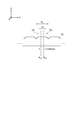
  • FIG. 28 is a cross-sectional view of the lens component 10 of the present embodiment.
  • FIG. 29 is a view for explaining image formation by the lens component 10 of the present embodiment.
  • Lens component 10 of the present embodiment includes a K-number of unit lenses 11 arranged in parallel in the minimum period P L in the Y-direction each have extending in the X direction of the common configurations.
  • Each unit lens 11 includes two partial lenses 12 1 and 12 2 that are divided within a minimum period P L in the Y direction. Further, a flat portion 13 provided between the partial lenses 12 1 and 12 2 is also included.
  • Each of the partial lenses 12 1 and 12 2 included in each unit lens 11 has optical axes A x1 and A x2 that are parallel to the Z direction and are different from each other, and the display panel 20 is used as an object plane.
  • the dots are imaged at different positions on the image plane A.
  • the distance between the positions of image formation by the partial lenses 12 1 and 12 2 depends on the lens magnification ⁇ and the distance between the optical axes A x1 and A x2 .
  • the focal lengths of the partial lenses 12 1 and 12 2 are equal to each other.
  • FIG. 29 schematically illustrates the optical path of only the light rays that pass through the partial lenses 12 1 and 12 2 out of the light rays that have emerged from the common point on the object plane.
  • the light rays that pass through the flat portion 13 among the light rays emitted from the common point on the object plane reach the image plane A in a distributed manner between the two image forming points.
  • the light that has passed through the flat portion 13 and reached the image plane A becomes noise with respect to the imaging light, but the amount of light per area is sufficiently small with respect to the imaging light. If the size of the flat portion 13 relative to the partial lenses 12 1 and 12 2 is not too large, this noise is not a problem. There is no problem as long as 0.5 or less length of the flat portion 13 which occupies the period P L in the cross-sectional shape shown in Figure 28.
  • Each of the partial lenses 12 1 and 12 2 included in each unit lens 11 can be formed in a shape that is a part of a cylindrical lens having the same shape, as shown in FIG. Figure in sectional view shown at 30, has the same radius of curvature are equal to each other and the circle C 1 and the circle C 2, the center O 1 of the circle C 1 is present on the optical axis A x1, center O 2 of the circle C 2 Exists on the optical axis A x2 .
  • the partial lenses 12 1 and 12 2 are part of a cylindrical shape made up of arcs.
  • the first example is a specific example of the above-described embodiment.
  • the lens is assumed to be a spherical lens.
  • FIG. 31 is a diagram illustrating calculation conditions of the third comparative example.
  • FIG. 32 is a diagram illustrating a calculation result of the third comparative example.
  • the width P in the Y direction of the unit pixel group is set to 0.2 mm.
  • the width W P of the fractional pixel each Y direction included in the unit pixel group was 0.06 mm.
  • the Y-direction width W B of the shielding area 23 between the parts pixels included in the unit pixel group was 0.04 mm.
  • the distance L 1 between the main plane and the image plane A of the exit side of the lens was 350 mm.
  • the distance L 2 between the principal plane of the incident side of the lens and the display panel 20 was 0.46 mm.
  • the lens thickness was 0.2 mm.
  • the lens radius of curvature was calculated to be 0.27 mm by solving the ray matrix using the values of these parameters.
  • the width of the display panel 20 in the Y direction is 32.2 mm, and the display panel 20 includes 161 unit pixel sets.
  • the width P L of the unit lens in the Y direction was calculated to be 0.11997 mm.
  • the light intensity distribution on the image plane A when all of the partial pixels 22 L and 22 R included in the 161 unit pixel group of the display panel 20 are illuminated is as shown in FIG. become.
  • the light is present a region I B do not reach.
  • Black areas I B for shielding region 23 is formed in a range in the Y direction represented by the formula (3).
  • FIG. 33 is a diagram showing calculation conditions of the first embodiment.
  • FIG. 34 is a diagram showing the calculation results of the first example.
  • the calculation conditions for parameters other than the unit lens shape are the same as the calculation conditions of the third comparative example.
  • each unit lens 11 includes partial lenses 12 1 and 12 2 and a flat portion 13.
  • the interval between the optical axes of the partial lenses 12 1 and 12 2 included in each unit lens 11 is equal to the width W B in the Y direction of the shielding region 23 between the partial pixels included in the unit pixel group, and is set to 0. 04 mm.
  • the inclination of the lens surface tangent on the YZ plane was made continuous within each unit lens surface.
  • the radius of curvature of each partial lens was 0.27 mm, and the width of each partial lens in the Y direction was 0.07985 mm.
  • Right eye image I R formed by the light emitted from the right eye portion pixels 22 R is formed in a range by partial lens 12 1 in the Y direction is represented by the following formula (13), following the partial lens 12 2 ( It is formed in the range in the Y direction represented by the formula (14), and formed in the range in the Y direction represented by the following formula (15) as a whole.
  • Left eye image I L formed by the light emitted from the left eye portion pixels 22 L is formed in a range in the Y direction is represented as a whole the following equation (16). Therefore, there is no region on the image plane A where light does not reach.
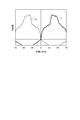
  • the light intensity distribution on the image plane A when all of the partial pixels 22 L and 22 R included in the 161 unit pixel group of the display panel 20 are illuminated is as shown in FIG. become.
  • the light has disappeared region I B does not reach black streaks when observing the image disappears.
  • each unit lens 11 when the partial lenses 12 1 and 12 2 exist to the center with the same curvature, except for the flat portion 13 from the configuration of the first example (when the configuration of the reference form),
  • FIG. 36 is a diagram showing calculation conditions of the second embodiment.
  • FIG. 37 is a diagram showing a calculation result of the second embodiment.
  • the distance between the optical axes A x1 and A x2 of the partial lenses 12 1 and 12 2 is changed to 0.05 mm, and the width of the flat portion 13 in the Y direction is changed.
  • the overlap amount between the right eye image I R and the left eye image I L increases, more effectively black streaks Can be eliminated.
  • FIG. 38 is a diagram showing calculation conditions of the third embodiment.
  • FIG. 39 is a diagram showing a calculation result of the third embodiment.
  • the distance between the optical axes A x1 and A x2 of the partial lenses 12 1 and 12 2 remains 0.04 mm, and the width of the flat portion 13 in the Y direction was changed to 0.099 mm.
  • the overlap amount between the right eye image I R and the left eye image I L will have significant crosstalk is entering amount of the other viewpoint slightly worse becomes the other hand against the viewpoint.
  • the distance between the partial lens 12 1, 12 2 of the optical axis if in the same or greater than the width W B of the shielding area 23, on the image plane A in the vicinity of y 0, overlapping the right-eye image I R and the left eye image I L from each other, it is possible to eliminate a black streak.
  • the lens component 10 of the present embodiment is configured as shown in a cross-sectional view in FIG. 40, that is, in each unit lens 11, the direction width of the flat portion 13 is narrower than the distance between the optical axes of the partial lenses 12 1 and 12 2. It may be a configuration. Even the lens component 10 having such a configuration can be manufactured more easily than the lens component 10 of the reference embodiment. However, as a configuration that can be more easily manufactured, in each unit lens, the width of the flat portion 13 in the Y direction is equal to or larger than the interval between the optical axes of the partial lenses 12 1 and 12 2 . Is preferred.
  • the flat portion 13 may be a curved surface having a radius of curvature larger than the radius of curvature of the partial lenses 11 1 and 11 2 .
  • the flat portion 13 may be a curved surface having a radius of curvature larger than the minimum value of the radius of curvature of the aspherical lens.
  • the flat part 13 does not have to image light emitted from the object plane on the image plane A.
  • FIG. 41 is a diagram schematically illustrating a method for producing a mold.
  • FIG. 42 is a diagram for explaining the shape of a cutting tool used in manufacturing a mold.
  • the cutting tool 31 includes a main body portion and a blade edge (not shown), and the blade edge is brazed to the tip of the main body portion so as to be integrally formed.
  • the cutting edge can be made of a hard material such as diamond.
  • the cutting tool 31 is movable in a predetermined direction while being held by a shank (not shown). Move the byte 31 in the direction of the arrow in the figure, to form one plurality of grooves which are arranged at a period P L on the main surface of the flat plate 32, to prepare a mold.
  • m processing (usually three times depending on the depth) is required to form one groove.
  • the mold In order to manufacture the lens component 10 including n (usually several hundred or more) unit lenses 11, the mold also needs n grooves. Therefore, the entire m ⁇ n line processing is required.
  • Such a cutting tool 31 is manufactured by polishing.
  • the tip (blade edge) of the cutting tool 31 has the same shape as the unit lens 11.
  • the cutting tool 31 used when manufacturing a mold for manufacturing the lens component 10 of the comparative example has one convex portion at the tip.
  • the cutting tool 31 ⁇ / b> A used when manufacturing a mold for manufacturing the lens component 10 of the reference form has a dent between two convex portions.
  • the cutting tool 31A having such a shape can be produced by polishing the tip (cutting edge) of the cutting tool 31.
  • the tip (blade edge) of the cutting tool 31 is made of a hard material with a small size, it is difficult to manufacture by ordinary polishing, and it is necessary to manufacture by a special technique, so that it is easy to manufacture. Not expensive.
  • the cutting tool 31D used when manufacturing the mold for manufacturing the lens component 10 of the present embodiment does not have a depression at the tip, so that the normal cutting tool 31 is used. Similarly to the above, it can be produced by ordinary polishing. Therefore, the lens component 10 of this embodiment can be easily manufactured at the same cost as a normal lenticular lens.
  • the number of viewpoints may generally be two or more, and each partial lens included in the unit lens may have an aspheric lens shape.
  • FIG. 43 is a diagram illustrating a positional relationship between the unit lens and the unit pixel group at the center of the image display apparatus according to the present embodiment.
  • the display panel 20 is centered.
  • the intermediate position in the Y direction of each of the two partial lenses included in any unit lens near the center in the Y direction of the lens component 10 and the center in the Y direction of the display panel 20 are near. It is desirable that the center position of any unit pixel group is equal to each other.
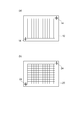
  • the lens component 10 has the mark 14 for alignment at the edge
  • the display panel 20 has the mark 24 for alignment at the edge.
  • the mark 14 and the mark 24 coincide with each other.
  • the present invention can display an image toward each of a plurality of viewpoints, can suppress deterioration of the image quality of the image, and can be easily manufactured, and the image display device. It can be used as an included lens component.

Landscapes

  • Physics & Mathematics (AREA)
  • General Physics & Mathematics (AREA)
  • Optics & Photonics (AREA)
  • Engineering & Computer Science (AREA)
  • Multimedia (AREA)
  • Signal Processing (AREA)
  • Nonlinear Science (AREA)
  • Chemical & Material Sciences (AREA)
  • Crystallography & Structural Chemistry (AREA)
  • Mathematical Physics (AREA)
  • Stereoscopic And Panoramic Photography (AREA)
  • Testing, Inspecting, Measuring Of Stereoscopic Televisions And Televisions (AREA)
  • Devices For Indicating Variable Information By Combining Individual Elements (AREA)
  • Optical Elements Other Than Lenses (AREA)

Abstract

レンズ部品10は、各々X方向に延在し共通の構成を有しY方向に最小周期Pで並列配置されたK個の単位レンズ11を備える。各単位レンズ11は、Y方向の最小周期P内において区分される2個の部分レンズ12,12を含み、さらに、これら部分レンズ12,12の間に設けられた平坦部13をも含む。部分レンズ12,12それぞれは、Z方向に平行であって互いに異なる光軸を有し、物体面上の共通点を像面A上の互いに異なる位置に結像する。

Description

レンズ部品および画像表示装置
 本発明は、複数の視点それぞれに向けて画像を表示することができる画像表示装置、および、この画像表示装置に含まれるレンズ部品に関するものである。
 複数の視点それぞれに向けて画像を表示することができる画像表示装置は、例えばカーナビゲーションシステム(Car Navigation System)において運転席および助手席それぞれに座っている者に対して互いに異なる画像を表示することができる。また、画像表示装置は、同一人物の右目および左目それぞれに対して互いに異なる画像を表示することで立体画像と認識させたりすることができる。
 このような画像表示装置として、液晶などを用いた表示パネルと、シリンドリカルレンズ(Cylindrical Lens)が並列配置されたレンチキュラレンズ(Lenticular Lens)と、を備えた画像表示装置が知られている。表示パネルとして液晶表示パネルが用いられる場合、ブラックマトリックスと呼ばれる遮蔽領域で個々の画素が囲まれている。表示パネルにおいて画素間に遮蔽領域が存在していることにより、画像表示装置が画像を表示する像面上では、遮蔽領域に対応する黒い領域が生じる。
 この黒い領域が像面上の位置によっては認識されることとなり、画像内で黒い筋となって観察されるので、画質が低下する。そこで、特許文献1に開示された発明は、液晶表示パネルとレンチキュラレンズとの間に異方性散乱シートを設けることで、画素間の遮蔽領域に起因する画質の低下を回避することを図ろうとしている。
特開2008-134617号公報
 しかしながら、特許文献1に開示された発明では、画像を形成するのに必要な光をも異方性散乱シートにより散乱させることになるため、これにより画質が低下する。このような画質低下を回避する為に、特殊な形状を有するレンズ部品をレンチキュラレンズに替えて用いることも考えられる。しかし、特殊形状のレンズ部品の製造は必ずしも容易でない。
 本発明は、上記問題点を解消する為になされたものであり、複数の視点それぞれに向けて高品質の画像を表示することができる画像表示装置、および、この画像表示装置において好適に用いられ容易に製造することができるレンズ部品を提供することを目的とする。
 本発明に係るレンズ部品は、物体面上の画像を像面上に結像するレンズ部品である。レンズ部品は、(1)各々第1方向に延在し共通の構成を有し、第1方向に垂直な第2方向に最小周期Pで並列配置されたK個の単位レンズを備える。(2)K個の単位レンズそれぞれは、第2方向の最小周期P内において区分されるM個の部分レンズと、これらM個の部分レンズの間に設けられた平坦部とを含む。(3)各単位レンズに含まれるM個の部分レンズそれぞれは、第1方向および第2方向の双方に垂直な第3方向に平行であって互いに異なる光軸を有し、物体面上の共通点を像面上の互いに異なる位置に結像する。K,Mは2以上の整数である。
 本発明に係るレンズ部品では、各単位レンズにおいて、平坦部の第2方向の幅が、M個の部分レンズそれぞれの光軸の間隔と比べて等しいか又は大きくてもよい。また、本発明に係るレンズ部品では、各単位レンズにおいて、平坦部の第2方向の幅が、該単位レンズの第2方向幅の1/2より小さくてもよい。また、本発明に係るレンズ部品では、各単位レンズに含まれるM個の部分レンズそれぞれが、互いに等しい焦点距離を有してもよい。
 本発明に係る画像表示装置は、(1)互いに垂直な第1方向および第2方向の双方に平行な面上に複数の単位画素組が2次元配列され、複数の単位画素組それぞれが第2方向に沿って配列されたN個の部分画素を含む表示パネルと、(2)表示パネルを物体面として該物体面上の画像を像面上に結像し、第2方向について単位画素組に対応して単位レンズが設けられている上記の本発明のレンズ部品と、を備える。Nは2以上の整数である。
 本発明に係る画像表示装置では、表示パネルの複数の単位画素組それぞれにおいて第2方向に沿ってN個の部分画素の相互の間に遮蔽領域が存在している。遮蔽領域の第2方向での幅は、レンズ部品の各単位レンズに含まれるM個の部分レンズそれぞれの光軸の第2方向での間隔と比べて等しいか又は小さい。
 本発明に係る画像表示装置では、M値が2であり、レンズ部品のK個の単位レンズのうち第2方向について中央付近にある何れかの単位レンズに含まれる2個の部分レンズそれぞれの光軸の第2方向での中間位置と、表示パネルの複数の単位画素組のうち第2方向について中央付近にある何れかの単位画素組の中央位置とが、互いに等しくてもよい。本発明に係る画像表示装置では、レンズ部品および表示パネルそれぞれが、両者を組み立てる際の位置合わせの為のマークを有してもよい。
 本発明によれば、複数の視点それぞれに向けて画像を表示することができ、その画像の画質の劣化を抑制することができ、また、容易に製造することができる。
第1比較例の画像表示装置1による画像表示の原理を模式的に示す図である。 第1比較例の画像表示装置1による画像表示における表示パネル20の画素と像面A上の像との関係を説明する図である。 第1比較例の画像表示装置1による画像表示における表示パネル20の画素と像面A上の像との関係を説明する図である。 参考形態の画像表示装置のレンズ部品10を説明する図である。 第1比較例における表示パネル20に対しレンズが-Y方向にシフトしたときの部分画素22からの光線の軌跡を示す図である。 第1比較例における表示パネル20に対しレンズが-Y方向にシフトしたときの像面A上の光強度分布を示す図である。 第1比較例における表示パネル20に対しレンズが+Y方向にシフトしたときの部分画素22からの光線の軌跡を示す図である。 第1比較例における表示パネル20に対しレンズが+Y方向にシフトしたときの像面A上の光強度分布を示す図である。 参考形態における部分画素22からの光線の軌跡を示す図である。 参考形態における像面A上の光強度分布を示す図である。 第1比較例の計算条件を示す図である。 第1比較例の計算結果を示す図である。 第1参考例の計算条件を示す図である。 第1参考例の計算結果を示す図である。 第2参考例の計算条件を示す図である。 第2参考例の計算結果を示す図である。 第3参考例の計算条件を示す図である。 第3参考例の計算結果を示す図である。 第2比較例の画像表示装置2による画像表示の原理を模式的に示す図である。 第2比較例の計算条件を示す図である。 第2比較例の計算結果を示す図である。 第4参考例の計算条件を示す図である。 第4参考例の計算結果を示す図である。 非球面レンズの断面形状を示す図である。 非球面レンズの最適化条件を示す図である。 第5参考例の計算条件を示す図である。 第5参考例の計算結果を示す図である。 本実施形態のレンズ部品10の断面図である。 本実施形態のレンズ部品10による結像を説明する図である。 本実施形態のレンズ部品10の形状を説明する断面図である。 第3比較例の計算条件を示す図である。 第3比較例の計算結果を示す図である。 第1実施例の計算条件を示す図である。 第1実施例の計算結果を示す図である。 第1実施例の構成から平坦部13を除いた場合の計算結果を示す図である。 第2実施例の計算条件を示す図である。 第2実施例の計算結果を示す図である。 第3実施例の計算条件を示す図である。 第3実施例の計算結果を示す図である。 本実施形態のレンズ部品10の他の形状例を説明する断面図である。 金型の作製方法を模式的に説明する図である。 金型の作製の際に用いるバイトの形状を説明する図である。 本実施形態の画像表示装置の中央での単位レンズと単位画素組との位置関係を示す図である。 レンズ部品10および表示パネル20の組み立て時の位置合わせの為のマークを説明する図である。
 以下、添付図面を参照して、本発明を実施するための形態を詳細に説明する。図面の説明において同一または同等の要素には同一の符号を付し、重複する説明を省略する。はじめに、比較例および参考形態の画像表示装置について説明する。次に、実施形態の画像表示装置について説明する。参考形態は、本発明の実施形態の構成の前提となるべき事項を説明するためのものである。説明の便宜のために図面においてXYZ直交座標系を示している。
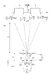
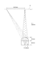
 図1は、第1比較例の画像表示装置1による画像表示の原理を模式的に示す図である。画像表示装置1は、レンズ部品10および表示パネル20を備える。画像表示装置1は、表示パネル20を物体面として該物体面上の画像をレンズ部品10により像面A上に結像する。
 レンズ部品10は、各々X方向に延在し共通の構成を有するシリンドリカルレンズ11~11が単位レンズとして一定周期でY方向に並列配置されたレンチキュラレンズである。Kは2以上の整数である。シリンドリカルレンズ11~11それぞれの光軸はZ方向に平行である。レンズ部品10は概略的には平板形状のものであって、表示パネル20に対向する面が平面であり、像面Aに対向する面が凸面となっている。図1ではレンズ部品10の凸面の形状が示されている。
 表示パネル20は、XY平面上に複数の単位画素組21が2次元配列されたものである。各単位画素組21は、Y方向に沿って配列された2個の部分画素22,22を含む。左目用部分画素22と右目用部分画素22とはY方向に交互に配置されている。ブラックマトリックスと呼ばれる遮蔽領域23が左目用部分画素22と右目用部分画素22との間に存在する。
 単位画素組21がシリンドリカルレンズ11に対応しているとすると、単位画素組21の左目用部分画素22から発した光がシリンドリカルレンズ11を経ることにより像面A上に左目用像Iが形成され、単位画素組21の右目用部分画素22から発した光がシリンドリカルレンズ11を経ることにより像面A上に右目用像Iが形成される。像面A上の左目用像Iの形成範囲にある左目Eの網膜には左目用画像が結像される。像面A上の右目用像Iの形成範囲にある右目Eの網膜には右目用画像が結像される。したがって、各単位画素組21の左目用部分画素22および右目用部分画素22それぞれに適切な画像データが与えられることにより、左目Eおよび右目Eにより立体画像が視認される。
 しかし、像面A上には、左目用像Iと右目用像Iとの間に、遮蔽領域23に対応する黒い領域Iが生じる。この黒い領域Iが像面A上の位置によっては認識されることとなり、立体画像内で黒い筋となって観察されるので、画質が低下する。
 図2および図3それぞれは、第1比較例の画像表示装置1による画像表示における表示パネル20の画素と像面A上の像との関係を説明する図である。単位画素組21に含まれる部分画素22,22それぞれのY方向の幅をWとする。単位画素組21に含まれる部分画素22と部分画素22との間の遮蔽領域23のY方向の幅をWとする。単位画素組21のY方向の幅をP(=2(W+W))とする。レンズ部品10の出射側の主平面と像面Aとの間の距離をLとする。レンズ部品10の入射側の主平面と表示パネル20との間の距離をLとする。
 部分画素22,22のY方向の幅を底辺とし距離Lを高さとする三角形と、像面Aにおける像I,IのY方向の幅を底辺とし距離Lを高さとする三角形とは、相似関係にある。厳密には、レンズ部品10と表示パネル20との間には他の部材(ガラス、偏光板、接着剤など)が存在する場合がある。レンズ厚が位置によらず一様にレンズ先端までの厚さと仮定した近軸計算では、距離Lは各層の厚さを各層の屈折率で割ったものの和となる。L,Lは、各部材の厚さ及び屈折率や設定した像面Aの位置(観察位置)に基づいて光線行列を解くことにより求められる。
 図2(a)では、単位画素組21のY方向の中心、および、単位画素組21に対応するシリンドリカルレンズ11のY方向の中心は、何れもY=0に位置している。このとき、図2(b)に示されるように、像面A上において、左目用部分画素22に対応する左目用像Iは下記(1)式で表されるY方向の範囲に形成され、右目用部分画素22に対応する右目用像Iは下記(2)式で表されるY方向の範囲に形成される。遮蔽領域23に対応する黒い領域Iは下記(3)式で表されるY方向の範囲に形成される。αは、レンズ倍率であり、α=L/Lなる式で表される。
Figure JPOXMLDOC01-appb-M000001
Figure JPOXMLDOC01-appb-M000002
Figure JPOXMLDOC01-appb-M000003
 図3(a)では、単位画素組21のY方向の中心はY=0に位置している。これに対して、単位画素組21に対応するシリンドリカルレンズ11のY方向の中心はY=-tに位置している。このとき、図3(b)に示されるように、像面A上において、左目用部分画素22に対応する左目用像Iは下記(4)式で表されるY方向の範囲に形成され、右目用部分画素22に対応する右目用像Iは下記(5)式で表されるY方向の範囲に形成される。遮蔽領域23に対応する黒い領域Iは下記(6)式で表されるY方向の範囲に形成される。
Figure JPOXMLDOC01-appb-M000004
Figure JPOXMLDOC01-appb-M000005
Figure JPOXMLDOC01-appb-M000006
 すなわち、図2の場合と比較して図3の場合には、単位画素組21に対してシリンドリカルレンズ11がY方向に-tだけ移動していることにより、像面A上において左目用像I,右目用像Iおよび黒い領域Iは何れもY方向に-t(1+L/L)だけシフトする。したがって、像面A上において図2では光強度が0であった部分にも図3では光が到達する。
 図4は、参考形態の画像表示装置のレンズ部品10を説明する図である。図4でもレンズ部品10の凸面の形状が示されている。図4(a),(b)は、各々X方向に延在し共通の構成を有する複数のシリンドリカルレンズが一定周期PでY方向に並列配置されたレンチキュラレンズを示す。このレンチキュラレンズは、第1比較例の画像表示装置1に含まれるものと同様のものである。図4(a)のレンチキュラレンズに対して図4(b)のレンチキュラレンズはY方向にtだけシフトしている。
 図4(c)に示される本参考形態のレンズ部品10は、各々X方向に延在し共通の構成を有しY方向に最小周期Pで並列配置されたK個の単位レンズ11を備える。各単位レンズ11は、Y方向の最小周期P内において区分される2個の部分レンズ12,12を含む。最小周期P内の0~P’の範囲にある部分レンズ12は図4(a)中の実線部分に相当する。最小周期P内のP’~Pの範囲にある部分レンズ12は図4(b)中の実線部分に相当する。
 すなわち、各単位レンズ11に含まれる2個の部分レンズ12,12それぞれは、Z方向に平行であって互いに異なる光軸(Y方向にtだけ互いに離れている光軸)を有し、物体面上の共通点を像面A上の互いに異なる位置(Y方向に-t(1+L/L)だけ互いにシフトした位置)に結像することができる。これにより、遮蔽領域23に対応する黒い領域I(観察の際に黒い筋となって見える領域)を狭くすることができ、或いは、黒い領域Iを無くすことができる。
 図2(b)および図3(b)それぞれに示された光強度分布から、下記(7)式で表される条件が成り立つとき、像面A上において光が到達しない領域Iが存在する。下記(8)式で表される条件が成り立つとき、像面A上において左目用像Iと右目用像Iとが互いに一部重なってクロストークが生じる。したがって、下記(9)式で表される条件が成り立つのが最適である。(7)式~(9)式それぞれにおいて、左辺は図2での黒い領域Iの左側境界位置を表し、右辺は図3での黒い領域Iの右側境界位置を表す。
Figure JPOXMLDOC01-appb-M000007
Figure JPOXMLDOC01-appb-M000008
Figure JPOXMLDOC01-appb-M000009
 上記(9)式から下記(10)式が得られる。通常、距離Lは数百μm~数mmであるのに対し、距離Lは数百mmと十分大きい。したがって、(10)式は下記(11)式で近似され得る。
Figure JPOXMLDOC01-appb-M000010
Figure JPOXMLDOC01-appb-M000011
 レンズ部品10の各単位レンズ11に含まれる部分レンズ12,12それぞれは、YZ断面において、球面レンズ形状を有していてもよいし、非球面レンズ形状を有していてもよい。部分レンズ12,12それぞれのレンズ形状は、光線行列を解くことにより得られる。しかし、部分レンズ12,12それぞれのレンズ形状が光線行列の解から数%程度異なっていても、充分に視点分離が可能であるので実用上の問題はない。ただし、像面A上におけるY方向の画質の一様性の観点から、各単位レンズ11に含まれる部分レンズ12,12それぞれは互いに等しい焦点距離を有するのが好ましい。
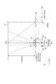
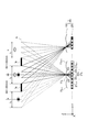
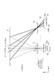
 次に、図5~図10を用いて第1比較例および本参考形態それぞれの画像表示装置の動作を説明する。図5は、第1比較例における表示パネル20に対しレンズが-Y方向にシフトしたときの部分画素22からの光線の軌跡を示す図である。図6は、第1比較例における表示パネル20に対しレンズが-Y方向にシフトしたときの像面A上の光強度分布を示す図である。図7は、第1比較例における表示パネル20に対しレンズが+Y方向にシフトしたときの部分画素22からの光線の軌跡を示す図である。図8は、第1比較例における表示パネル20に対しレンズが+Y方向にシフトしたときの像面A上の光強度分布を示す図である。図9は、本参考形態における部分画素22からの光線の軌跡を示す図である。図10は、本参考形態における像面A上の光強度分布を示す図である。
 第1比較例において、図5および図6に示されるように、表示パネル20に対しレンズが-Y方向にシフトしたとき(図4(a)の場合)、像面A上の右目用像IR1および左目用像IL1も-Y方向にシフトする。一方、図7および図8に示されるように、表示パネル20に対しレンズが+Y方向にシフトしたとき(図4(b)の場合)、像面A上の右目用像IR2および左目用像IL2も+Y方向にシフトする。
 これに対して、本参考形態においては、図9および図10に示されるように、単位レンズ11のうちの部分レンズ12を経て像面Aに形成される右目用像IR1および左目用像IL1と、単位レンズ11のうちの部分レンズ12を経て像面Aに形成される右目用像IR2および左目用像IL2とは、像面A上において互いに異なる領域に形成される(図10(a))。したがって、本参考形態では、像面A上において、右目用像IR1と右目用像IR2とが重なった右目用像Iが形成され、左目用像IL1と左目用像IL2とが重なった左目用像Iが形成される(図10(b))。
 次に、第1比較例,第1参考例,第2参考例および第3参考例それぞれにおける像面A上での光強度分布の計算例を説明する。第1参考例,第2参考例および第3参考例は、上記の本参考形態の具体的な例である。以下の計算例では、レンズは球面レンズであるとした。
 図11は、第1比較例の計算条件を示す図である。図12は、第1比較例の計算結果を示す図である。第1比較例では、図11に示されるように、単位画素組のY方向の幅Pを0.2mmとした。単位画素組に含まれる各部分画素それぞれのY方向の幅Wを0.08mmとした。単位画素組に含まれる各部分画素の間の遮蔽領域23のY方向の幅Wを0.02mmとした。
 レンズの出射側の主平面と像面Aとの間の距離Lを350mmとした。レンズの入射側の主平面と表示パネル20との間の距離Lを0.52mmとした。レンズの厚さを0.3mmとした。レンズの屈折率を1.6とした。レンズと表示パネル20との間に厚さ0.5mmで屈折率1.5のガラスがあるものとして、距離Lを0.52mm(=0.3/1.6+0.5/1.5)とした。実際にはレンズと表示パネル20との間に偏光板や接着剤が存在する場合があるが、これらを無視した。
 これらのパラメータの値を用いて光線行列を解くことにより、レンズの曲率半径は0.31mmと計算された。表示パネル20のY方向の幅を32.2mmとして、表示パネル20が161個の単位画素組を備えるものとした。
 図11中において、Y=80P=16mmに位置する最外単位画素組は、中央(Y=0)に位置する単位画素組から数えて80番目の単位画素組である。像面A上において各単位画素組から到達した像を視認範囲で概ね重ねるために、Y=80Pに位置する80番目の単位画素組の中心位置の像が、Y=80Pに位置する80番目のレンズを通って、像面A上のY=0の位置に来るようにした。前述と同様の三角形の相似関係から、単位レンズのY方向の幅Pは0.1997mmと計算された。
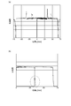
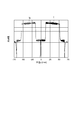
 第1比較例において、表示パネル20の161個の単位画素組に含まれる部分画素22,22の全てを光らせたときの像面A上での光強度分布は、図12に示されるようになる。像面A上において、右目用像Iと左目用像Iとの間に、光が到達しない領域Iが存在している。
 図13は、第1参考例の計算条件を示す図である。図14は、第1参考例の計算結果を示す図である。第1参考例では、図13に示されるように、単位レンズ形状以外のパラメータについての計算条件は上記の第1比較例の計算条件と同じである。この第1参考例では、単位レンズは、第1比較例のレンズを-Y方向(左方向)にt/2だけシフトしたレンズの一部に相当する部分レンズ12と、第1比較例のレンズを+Y方向(右方向)にt/2だけシフトしたレンズの一部に相当する部分レンズ12とを含む。t/2=W/2=0.01mmである。
 部分レンズ12,12それぞれの光軸は、Z方向に平行であって、互いに距離tだけ離れている。レンズ部品10の中央に位置する単位レンズに含まれる部分レンズ12,12それぞれの光軸のY方向の中心位置は、表示パネル20の中央に位置する単位画素組のY方向の中心位置と一致している。各単位レンズのY方向の幅P(0.1997mm)において、-Y方向側の0.05mm幅の領域に部分レンズ12が存在し、+Y方向側の0.1497mm幅の領域に部分レンズ12が存在する。
 第1参考例において、表示パネル20の161個の単位画素組に含まれる部分画素22,22の全てを光らせたときの像面A上での光強度分布は、図14に示されるようになる。像面A上において、右目用像Iと左目用像Iとの間に、光が到達しない領域Iがなくなっており、画像を観察したときの黒い筋がなくなる。図14では、光強度が位置によって階段状に変化していて光強度が低い領域があるが、光強度0で黒となって観察される領域より、人間の眼には遥かに認識されにくい。
 図15は、第2参考例の計算条件を示す図である。図16は、第2参考例の計算結果を示す図である。第2参考例では、図15に示されるように、単位レンズ形状以外のパラメータについての計算条件は上記の第1比較例の計算条件と同じである。前の第1参考例では部分レンズ12,12のY方向の幅の比が略1:3であったのに対して、この第2参考例では部分レンズ12,12のY方向の幅の比を1:1とした。
 第2参考例において、表示パネル20の161個の単位画素組に含まれる部分画素22,22の全てを光らせたときの像面A上での光強度分布は、図16に示されるようになる。像面A上において、右目用像Iと左目用像Iとの間に、光が到達しない領域Iがなくなっており、画像を観察したときの黒い筋がなくなる。第2参考例では、像面A上の光強度分布はY=0の位置を中心として対称となるので、より自然な画像が得られる。第2参考例のレンズ部品10は、第1参考例と異なり不連続部分がなくなるので、製造がより容易になる。
 図17は、第3参考例の計算条件を示す図である。図18は、第3参考例の計算結果を示す図である。第3参考例では、図17に示されるように、第1比較例,第1参考例および第2参考例と同様に、単位画素組のY方向の幅Pを0.2mmとし、レンズの出射側の主平面と像面Aとの間の距離Lを350mmとし、レンズの入射側の主平面と表示パネル20との間の距離Lを0.52mmとし、単位レンズのY方向の幅Pを0.1997mmとした。
 第3参考例では、単位画素組に含まれる各部分画素それぞれのY方向の幅Wを0.05mmとし、単位画素組に含まれる各部分画素の間の遮蔽領域23のY方向の幅Wを0.05mmとして、両者を等しくした。部分レンズ12,12のY方向の幅の比を1:1とした。
 第1比較例において、単位画素組に含まれる各部分画素それぞれのY方向の幅Wと各部分画素の間の遮蔽領域23のY方向の幅Wとを互いに等しくすると、像面Aにおいて、右目用像I、左目用像Iおよび黒い領域IそれぞれのY方向の幅も互いに等しくなる。これに対して、第3参考例では、表示パネル20の161個の単位画素組に含まれる部分画素22,22の全てを光らせたときの像面A上での光強度分布は、図18に示されるように、部分レンズ12,12により±t/2だけシフトされた右目用像Iおよび左目用像Iの重ね合わせとなるので、略均一の強度分布となる。
 したがって、第3参考例では、第2参考例の効果に加えて、強度分布が一様であり、より自然な画像が得られるという効果が得られる。さらに、像面Aでの実質的な視認範囲(すなわち、光強度分布が略一様である範囲)は、第1参考例および第2参考例では、右目用像Iに対してはY=-55mm~-13mmであって、左目用像Iに対してはY=+13mm~+55mmであったのに対し、第3参考例では、右目用像Iに対してはY=-65mm~0であって、左目用像Iに対してはY=0~+65mmであり、それぞれ視認範囲を広くとることができる。
 図18(a)において、右目用像Iおよび左目用像Iそれぞれの中央付近に、局所的に強度の大きい部分が見られる。これは、+Y方向にシフトした部分レンズによる像と、-Y方向にシフトした部分レンズによる像との切替部分で、レンズの球面収差により若干光強度分布が裾を引いて僅かなオーバーラップ(図18(b)中の点線で囲った部分)が生じたことに起因する。しかしながら、人間の眼には、このような局所的な強度の変化は認識されにくい。この僅かなオーバーラップは、画素の幅やレンズのシフト量に若干の修正を加えることなどにより改善が可能である。
 これまで説明してきた比較例および参考形態では視点数が2であったが、一般に視点数が2以上であってもよい。視点数がNである場合、表示パネル20の各単位画素組はY方向に配列されたN個の部分画素を含む。すなわち、N枚の絵を画素毎に分割し、表示パネル20上ではY方向に、1番目の絵を構成する部分画素、2番目の絵を構成する部分画素、・・・、N番目の絵を構成する部分画素の順に配置したものを単位画素組として、レンズによって各視点の像を振り分ける。
 次に、視点数が3である場合について説明する。図19は、第2比較例の画像表示装置2による画像表示の原理を模式的に示す図である。画像表示装置2は、レンズ部品10および表示パネル20を備え、表示パネル20を物体面として該物体面上の画像をレンズ部品10により像面A上に結像する。レンズ部品10は、図1に示されたものと同様である。
 表示パネル20は、XY平面上に複数の単位画素組21が2次元配列されたものである。視点数が3である場合、各単位画素組21は、Y方向に沿って配列された3個の第1の部分画素22,第2の部分画素22および第3の部分画素22を含む。部分画素22,22,22はY方向に順に配置されている。ブラックマトリックスと呼ばれる遮蔽領域23が、部分画素22と部分画素22との間に存在し、部分画素22と部分画素22との間に存在する。
 単位画素組21がシリンドリカルレンズ11に対応しているとすると、単位画素組21の第1部分画素22から発した光がシリンドリカルレンズ11を経ることにより像面A上に第1の像Iが形成される。単位画素組21の第2部分画素22から発した光がシリンドリカルレンズ11を経ることにより像面A上に第2の像Iが形成される。単位画素組21の第3部分画素22から発した光がシリンドリカルレンズ11を経ることにより像面A上に第3の像Iが形成される。像面A上の第1および第2の像の形成範囲にある左目・右目により立体画像が視認され、像面A上の第2および第3の像の形成範囲にある左目・右目により他の立体画像が視認される。
 しかし、この場合にも、像面A上には、第1の像Iと第2の像Iとの間、および、第2の像Iと第3の像Iとの間に、遮蔽領域23に対応する黒い領域Iが生じる。この黒い領域Iが像面A上の位置によっては認識されることとなり、立体画像内で黒い筋となって観察されるので、画質が低下する。
 このような視点数が3である場合にも、既に説明した視点数が2であるの場合と同様に、図4(c)に示されるようなレンズ部品10を用いることにより、遮蔽領域23に対応する黒い領域I(観察の際に黒い筋となって見える領域)を狭くすることができ、或いは、黒い領域Iを無くすことができる。
 次に、視点数が3である場合の第2比較例および第4参考例それぞれにおける像面A上での光強度分布の計算例を説明する。第4参考例は、上記の視点数が3である場合の参考形態の具体的な例である。以下の計算例では、レンズは球面レンズであるとした。
 図20は、第2比較例の計算条件を示す図である。図21は、第2比較例の計算結果を示す図である。第2比較例では、図20に示されるように、単位画素組のY方向の幅Pを0.21mmとした。単位画素組に含まれる各部分画素それぞれのY方向の幅Wを0.056mmとした。単位画素組に含まれる各部分画素の間の遮蔽領域23のY方向の幅Wを0.014mmとした。
 レンズの出射側の主平面と像面Aとの間の距離Lを350mmとした。レンズの入射側の主平面と表示パネル20との間の距離Lを0.39mmとした。レンズの厚さを0.2mmとした。レンズの屈折率を1.6とした。レンズと表示パネル20との間に厚さ0.4mmで屈折率1.5のガラスがあるものとして、距離Lを0.39mm(=0.2/1.6+0.4/1.5)とした。実際にはレンズと表示パネル20との間に偏光板や接着剤が存在する場合があるが、これらを無視した。
 これらのパラメータの値を用いて光線行列を解くことにより、レンズの曲率半径は0.235mmと計算された。表示パネル20のY方向の幅を33.81mmとして、表示パネル20が161個の単位画素組を備えるものとした。
 図20中において、Y=80P=16.8mmに位置する最外単位画素組は、中央(Y=0)に位置する単位画素組から数えて80番目の単位画素組である。像面A上において各単位画素組から到達した像を視認範囲で概ね重ねるために、Y=80Pに位置する80番目の単位画素組の中心位置の像が、Y=80Pに位置する80番目のレンズを通って、像面A上のY=0の位置に来るようにした。前述と同様の三角形の相似関係から、単位レンズのY方向の幅Pは0.2098mmと計算された。
 第2比較例において、表示パネル20の161個の単位画素組に含まれる3個の部分画素22~22の全てを光らせたときの像面A上での光強度分布は、図21に示されるようになる。像面A上において、像I~像Iの間に、光が到達しない領域Iが存在している。
 図22は、第4参考例の計算条件を示す図である。図23は、第4参考例の計算結果を示す図である。第4参考例では、図22に示されるように、単位レンズ形状以外のパラメータについての計算条件は上記の第2比較例の計算条件と同じである。第4参考例では、単位レンズは、第2比較例のレンズを-Y方向(左方向)にt/2だけシフトしたレンズの一部に相当する部分レンズ12と、第2比較例のレンズを+Y方向(右方向)にt/2だけシフトしたレンズの一部に相当する部分レンズ12とを含む。t/2=W/2=0.007mmである。
 部分レンズ12,12それぞれの光軸は、Z方向に平行であって、互いに距離tだけ離れている。レンズ部品10の中央に位置する単位レンズに含まれる部分レンズ12,12それぞれの光軸のY方向の中心位置は、表示パネル20の中央に位置する単位画素組のY方向の中心位置と一致している。部分レンズ12,12のY方向の幅の比を1:1とした。
 第4参考例において、表示パネル20の161個の単位画素組に含まれる部分画素22~22の全てを光らせたときの像面A上での光強度分布は、図23に示されるようになる。像面A上において、像I~像Iの間に、光が到達しない領域Iがなくなっており、画像を観察したときの黒い筋がなくなる。光強度が位置によって階段状に変化していて光強度が低い領域があるが、光強度0で黒となって観察される領域より、人間の眼には遥かに認識されにくい。
 これまで説明してきた比較例および参考形態では、単位レンズに含まれる各部分レンズが球面レンズ形状であったが、非球面レンズ形状であってもよい。単位レンズに含まれる各部分レンズを非球面レンズ形状とすることで、画素上の1点から出た光を像面A上なるべく径の小さい1点に結像させることができる。本参考形態では、レンズがX方向に延在しているので、像面A上なるべく細い線に結像させることができる。
 次に、単位レンズに含まれる各部分レンズが非球面レンズ形状である場合について説明する。図24は、非球面レンズの断面形状を示す図である。光軸をZ軸に一致させ、光軸からの距離をrとし、r=0のときのレンズ高さとの差をΔzとすると、非球面レンズの凸面の形状は下記(12)式で表される。cは曲率である。kはコーニック係数である。c2mは非球面係数である。
Figure JPOXMLDOC01-appb-M000012
 これらc,k,c2mのレンズパラメータは、市販されているレンズ設計ソフトを用いて最適化し決定することができる。最適化の際の条件として、中央単位画素組から最外単位画素組までの数をNとし、物体高(レンズ中心から最も遠い発光点のY方向の距離)を例えばN(P-P)+P/2
とし、レンズ倍率をL/Lとすればよい。
 本参考形態における単位レンズに含まれる各部分レンズは、球面レンズ形状の場合と同様に、非球面レンズ形状の場合にも、遮蔽領域23のY方向の幅tだけ互いにシフトしたレンズの一部同士を組み合わせることにより、像面A上において光を到達しない部分をなくすことができ、画像の質を高めつつ、画面上に現れる黒い筋を無くすことができる。
 非球面レンズのパラメータは以下のようにして計算される。図25に示されるように、屈折率1.5で厚さ0.5mmの平行平板ガラスに、屈折率1.6で厚さ0.3mmの片面が平面で片面が非球面凸形状のレンズが、平面側で密着したレンズ系において、レンズと密着しているガラスの面に対向する面を光源面とする。物体高0、0.124mm(=80×(0.2-0.1997)+0.2/2)に対し、レンズ部品10の出射側の主平面と像面Aとの間の距離Lを350mmとし、レンズ部品10の入射側の主平面と表示パネル20との間の距離Lを0.52mmとする。この条件の下で最適化することにより、c=3.1[mm-1]、k=-0.76、c=3.9、c=-145.5が得られた。cおよびc2m(m≧4)を0とした。
 次に、単位レンズに含まれる各部分レンズが非球面レンズである場合の第5参考例における像面A上での光強度分布の計算例を説明する。
 図26は、第5参考例の計算条件を示す図である。図27は、第5参考例の計算結果を示す図である。第5参考例では、図26に示されるように、単位レンズ形状以外のパラメータについての計算条件は上記の第2参考例の計算条件と同じである。この第5参考例では、単位レンズに含まれる各部分レンズを上記のような非球面レンズ形状とした。
 第5参考例において、表示パネル20の161個の単位画素組に含まれる部分画素22,22の全てを光らせたときの像面A上での光強度分布は、図27に示されるようになる。像面A上において、右目用像Iと左目用像Iとの間に、光が到達しない領域Iがなくなっており、画像を観察したときの黒い筋がなくなる。第5参考例では、像面A上の光強度分布はY=0の位置を中心として対称となるので、より自然な画像が得られる。第5参考例のレンズ部品10は、不連続部分がなくなるので、製造がより容易になる。
 次に、参考形態のレンズ部品10と対比しつつ、本実施形態のレンズ部品10について説明する。これまで説明してきた参考形態のレンズ部品10は、比較例のものと比べて、画像の画質の劣化を抑制することができる点で優れているが、製造の容易性の点では難がある。すなわち、参考形態のレンズ部品10は、XZ断面において各単位レンズ11に含まれる部分レンズ12と部分レンズ12との間に窪みを有していることから、製造の際に用いられる金型の加工が容易ではない。以下に説明する本実施形態のレンズ部品10は、参考形態のレンズ部品10と同程度の画質劣化抑制の作用効果を奏することに加えて、容易に製造することができるものである。
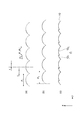
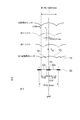
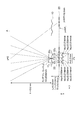
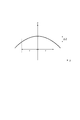
 図28は、本実施形態のレンズ部品10の断面図である。図29は、本実施形態のレンズ部品10による結像を説明する図である。本実施形態のレンズ部品10は、各々X方向に延在し共通の構成を有しY方向に最小周期Pで並列配置されたK個の単位レンズ11を備える。各単位レンズ11は、Y方向の最小周期P内において区分される2個の部分レンズ12,12を含む。さらに、これら部分レンズ12,12の間に設けられた平坦部13をも含む。各単位レンズ11に含まれる部分レンズ12,12それぞれは、Z方向に平行であって互いに異なる光軸Ax1,Ax2を有し、表示パネル20を物体面として該物体面上の共通点を像面A上の互いに異なる位置に結像する。部分レンズ12,12それぞれによる結像の位置の間の距離は、レンズ倍率αと光軸Ax1,Ax2間の距離とに依存する。部分レンズ12,12それぞれの焦点距離は互いに等しい。
 図29は、物体面上の共通点から出た光線のうち部分レンズ12,12を通過する光線のみの光路を模式的に描いたものである。図29には示されていないが、物体面上の共通点から出た光線のうち平坦部13を通過する光線は、像面A上で2つの結像点の間に分布して到達する。平坦部13を通過して像面A上に到達した光は、結像光に対する雑音となるが、面積当たりの光量では結像光に対して十分小さくなる。部分レンズ12,12に対する平坦部13の大きさが大きすぎなければ、この雑音は問題ない。図28に示された断面形状において周期Pに占める平坦部13の長さが0.5以下であれば問題ない。
 各単位レンズ11に含まれる部分レンズ12,12それぞれは、図30に示されるように、同じ形状の円筒レンズの一部である形状で構成することができる。図30で示した断面図では、円Cと円Cとは互いに等しい同じ曲率半径を持ち、円Cの中心Oが光軸Ax1上に存在し、円Cの中心Oが光軸Ax2上に存在する。部分レンズ12,12は各円弧からなる円筒形状の一部である。
 次に、図31~図39を用いて第3比較例,第1実施例,第2実施例および第3実施例それぞれにおける像面A上での光強度分布の計算例を説明する。第1実施例は、上記の本実施形態の具体的な例である。以下の計算例では、レンズは球面レンズであるとした。
 図31は、第3比較例の計算条件を示す図である。図32は、第3比較例の計算結果を示す図である。第3比較例では、図31に示されるように、単位画素組のY方向の幅Pを0.2mmとした。単位画素組に含まれる各部分画素それぞれのY方向の幅Wを0.06mmとした。単位画素組に含まれる各部分画素の間の遮蔽領域23のY方向の幅Wを0.04mmとした。
 レンズの出射側の主平面と像面Aとの間の距離Lを350mmとした。レンズの入射側の主平面と表示パネル20との間の距離Lを0.46mmとした。レンズの厚さを0.2mmとした。レンズの屈折率を1.6とした。レンズと表示パネル20との間に厚さ0.5mmで屈折率1.5のガラスがあるものとして、距離Lを0.46mm(=0.2/1.6+0.5/1.5)とした。実際にはレンズと表示パネル20との間に偏光板や接着剤が存在する場合があるが、これらを無視した。
 これらのパラメータの値を用いて光線行列を解くことにより、レンズの曲率半径は0.27mmと計算された。表示パネル20のY方向の幅を32.2mmとして、表示パネル20が161個の単位画素組を備えるものとした。
 図31中において、Y=80P=16mmに位置する最外単位画素組は、中央(Y=0)に位置する単位画素組から数えて80番目の単位画素組である。像面A上において各単位画素組から到達した像を視認範囲で概ね重ねるために、Y=80Pに位置する80番目の単位画素組の中心位置の像が、Y=80Pに位置する80番目のレンズを通って、像面A上のY=0の位置に来るようにした。前述と同様の三角形の相似関係から、単位レンズのY方向の幅Pは0.1997mmと計算された。
 第3比較例において、表示パネル20の161個の単位画素組に含まれる部分画素22,22の全てを光らせたときの像面A上での光強度分布は、図32に示されるようになる。像面A上において、右目用像Iと左目用像Iとの間に、光が到達しない領域Iが存在している。遮蔽領域23に対する黒い領域Iは、前記(3)式で表されるY方向の範囲に形成される。
 図33は、第1実施例の計算条件を示す図である。図34は、第1実施例の計算結果を示す図である。第1実施例では、図33に示されるように、単位レンズ形状以外のパラメータについての計算条件は上記の第3比較例の計算条件と同じである。この第1実施例では、各単位レンズ11は、部分レンズ12,12および平坦部13を含む。各単位レンズ11に含まれる部分レンズ12,12それぞれの光軸の間の間隔を、単位画素組に含まれる各部分画素の間の遮蔽領域23のY方向の幅Wと等しく0.04mmとした。YZ面におけるレンズ面接線の傾きを各単位レンズ面内で連続とした。各部分レンズの曲率半径を0.27mmとし、各部分レンズのY方向の幅を0.07985mmとした。
 物体面上の或る物点から出た光は、その点と光軸との距離のα倍だけ、光軸から物点と反対側に離れた像面A上に結像する。右目用部分画素22から出た光により形成される右目用像Iは、部分レンズ12によって下記(13)式で表されるY方向の範囲に形成され、部分レンズ12によって下記(14)式で表されるY方向の範囲に形成され、全体として下記(15)式で表されるY方向の範囲に形成される。左目用部分画素22から出た光により形成される左目用像Iは、全体として下記(16)式で表されるY方向の範囲に形成される。よって、像面A上において光が到達しない領域が存在しないことになる。
Figure JPOXMLDOC01-appb-M000013
Figure JPOXMLDOC01-appb-M000014
Figure JPOXMLDOC01-appb-M000015
Figure JPOXMLDOC01-appb-M000016
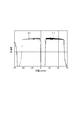
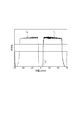
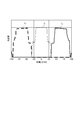
 第1実施例において、表示パネル20の161個の単位画素組に含まれる部分画素22,22の全てを光らせたときの像面A上での光強度分布は、図34に示されるようになる。像面A上において、右目用像Iと左目用像Iとの間に、光が到達しない領域Iがなくなっており、画像を観察したときの黒い筋がなくなる。
 各単位レンズ11において、第1実施例の構成から平坦部13を除いて、部分レンズ12,12それぞれが同じ曲率を有したまま中央まで存在する場合(参考形態の構成とした場合)、像面A上での光強度分布は、図35に示されたようになる。図35と比較して、図34に示される第1実施例の計算結果は、若干の強度分布の違いがあるものの、左右方向への視点分離を維持しつつ、y=0mm付近の光強度0の領域がなくなっているので、十分な性能を有していると言える。
 図36は、第2実施例の計算条件を示す図である。図37は、第2実施例の計算結果を示す図である。第1実施例に対して、第2実施例では、部分レンズ12,12それぞれの光軸Ax1,Ax2の間の距離を0.05mmに変更し、平坦部13のY方向の幅を0.05mmに変更した。第1実施例と比べて、第2実施例では、像面A上でy=0付近において、右目用像Iと左目用像Iとの重なり量が大きくなり、より効果的に黒い筋をなくすことができる。
 図38は、第3実施例の計算条件を示す図である。図39は、第3実施例の計算結果を示す図である。第1実施例に対して、第3実施例では、部分レンズ12,12それぞれの光軸Ax1,Ax2の間の距離を0.04mmのままとし、平坦部13のY方向の幅を0.099mmに変更した。第1実施例および第2実施例と同様、第3実施例でも、像面A上でy=0付近において、右目用像Iと左目用像Iとが互いに重なり、黒い筋をなくすことができる。第3実施例では、右目用像Iと左目用像Iとの重なり量がかなり大きくなり、一方視点に対する他方視点の入り込み量でありクロストークが若干悪くはなる。しかし、一般的な人の眼間距離は60~65mmであり、片目の位置であるy=±30~32.5mm付近には他視点の光が混入していないので、立体画像表示装置に用いることが可能である。
 上記の第1~第3の実施例のように、部分レンズ12,12の光軸間の距離を遮蔽領域23の幅Wと同じかそれ以上にしておけば、像面A上でy=0付近において、右目用像Iと左目用像Iとが互いに重なり、黒い筋をなくすことができる。
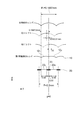
 本実施形態のレンズ部品10は、図40に断面図が示されるような構成、すなわち、各単位レンズ11において平坦部13の方向幅が部分レンズ12,12の光軸間の距離より狭い構成であってもよい。このような構成のレンズ部品10であっても、参考形態のレンズ部品10より容易に製造することができる。しかし、より容易に製造することができる構成としては、各単位レンズにおいて、平坦部13のY方向の幅は、部分レンズ12,12それぞれの光軸の間隔と比べて等しいか又は大きいのが好ましい。
 一方、平坦部13を通る光は結像に寄与しない雑音光となるので、平坦部13のY方向の幅が大きすぎると雑音光が増してしまう。したがって、各単位レンズ11において、平坦部13のY方向の幅は、該単位レンズ11のY方向の幅Pの1/2より小さいのが好ましい。
 平坦部13を通る光は雑音光となるだけであるので、平坦部13は、通過後の光の進行方向を厳密に制御する必要はない。したがって、平坦部13は、完全な平面でなくてもよく、例えば波長の10倍程度以下の表面粗さであれば問題ない。平坦部13は、部分レンズ11,11の曲率半径より大きい曲率半径を有する曲面であってもよい。部分レンズ11,11が非球面レンズである場合には、平坦部13は、その非球面レンズの曲率半径の最小値より大きい曲率半径を有する曲面であってもよい。平坦部13は、物体面上から発した光を像面A上に結像しなければよい。
 次に、比較例、参考形態および本実施形態それぞれの場合におけるレンズ部品10の製造方法について説明する。レンズ部品10のレンズ面の形状の凹凸を反転させた形状を有する金型を作製し、溶かした材料を金型に流し込んで上から平板でプレスするか、或いは、溶かした材料を平板に流し込んで上から金型でプレスするかすることで、レンズ部品10を製造する。図41は、金型の作製方法を模式的に説明する図である。図42は、金型の作製の際に用いるバイトの形状を説明する図である。バイト31は本体部と刃先(図示せず)とから構成されており、刃先は本体部の先端にろう付けされて一体に構成されている。刃先はダイヤモンドなどの硬い材料で構成され得る。バイト31は図示しないシャンクに保持された状態で所定方向に移動可能とされている。バイト31を図中の矢印の方向に動かし、平板32の一方の主面上に周期Pで配列された複数の溝を形成して、金型を作製する。
 バイト31の1回のライン加工で切り込める深さが限られるので、1本の溝を形成するためにはm回(深さに依存するが通常は3回)のライン加工が必要となる。n個(通常は数百以上)の単位レンズ11を備えるレンズ部品10を製造するには、金型もn本の溝が必要である。したがって、全体のm×n回のライン加工が必要となる。このようなバイト31は研磨により作製される。
 バイト31の先端(刃先)は単位レンズ11と同じ形状を有する。比較例のレンズ部品10を製造するための金型を作製する際に用いられるバイト31は、その先端が1つの凸部を有する。参考形態のレンズ部品10を製造するための金型を作製する際に用いられるバイト31Aは、図42(a)に示されるように、その先端が2つの凸部の間に窪みを有する。このような形状を有するバイト31Aは、バイト31の先端(刃先)を研磨することで作製され得る。しかし、バイト31の先端(刃先)は、サイズが小さく、硬い材料で構成されているから、通常の研磨により作製することが困難であり、特殊な技術により作製する必要があるので、作製が容易でなく高価となる。バイト31Aに替えて、図42(b)に示されるような2本のバイト31B,31Cを用いることも考えられる。しかし、この場合には、必要なバイトの本数が増えるだけでなく、金型作成の際のライン加工の回数が2倍になるので、金型作製のコストが倍増する。さらに、こうして作製された金型は、2本のバイトの境界部に筋状の加工残りが発生してしまうから、単位レンズの光学特性が劣化する。
 本実施形態のレンズ部品10を製造するための金型を作製する際に用いられるバイト31Dは、図42(c)に示されるように、先端に窪みを有していないので、通常のバイト31と同様に通常の研磨により作製することができる。したがって、本実施形態のレンズ部品10は、通常のレンチキュラレンズと同じコストで容易に製造することができる。
 本実施形態においても、参考形態の場合と同様に、一般に視点数が2以上であってよく、単位レンズに含まれる各部分レンズが非球面レンズ形状であってもよい。
 これまで、立体画像を視認させる場合について主に説明してきた。立体画像を表示する画像表示装置や、視点を非対称に振り分けることを目的としていない画像表示装置では、図43に示されるように、画像表示装置の正面中央で見たときに、左右に均等に各視点の像が形成されていることが好ましい。図43は、本実施形態の画像表示装置の中央での単位レンズと単位画素組との位置関係を示す図である。
 図43に示されるように、像面A上において、Y方向の中央(Y=0)の位置に対して負の方向を右視点とし、正の方向を左視点とすると、表示パネル20において中央の単位画素組21の中心がY=0に位置する。画素と像とは互いに反転するので、負側に左目用部分画素22が配置され、正側に右目用部分画素22が配置されている必要がある。これが大きくずれると、両視点の外側の虚像の部分が見えてしまい、完全に右目用部分画素と左目用部分画素が入れ替わると、右と左とで像が入れ替わってしまう。したがって、レンズ部品10のY方向について中央付近にある何れかの単位レンズに含まれる2個の部分レンズそれぞれの光軸のY方向での中間位置と、表示パネル20のY方向について中央付近にある何れかの単位画素組の中央位置とが、互いに等しいことが望ましい。
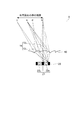
 図43に示されるような望ましい単位レンズ11と単位画素組21との位置関係にするためには、レンズ部品10と表示パネル20とを組み立てる際に画像を表示させることで位置を確認しながら組み立てることが好ましい。或いは、図44に示されるように、レンズ部品10が位置合わせの為のマーク14を縁に有し、表示パネル20が位置合わせの為のマーク24を縁に有するようにして、レンズ部品10と表示パネル20とを組み立てる際にマーク14とマーク24とを互いに一致させるようにすることが好ましい。
 本発明は、複数の視点それぞれに向けて画像を表示することができ、その画像の画質の劣化を抑制することができ、また、容易に製造することができる画像表示装置及びこの画像表示装置に含まれるレンズ部品として利用可能である。
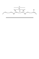
 1,2…画像表示装置、10…レンズ部品、11…単位レンズ、12…部分レンズ、13…平坦部、20…表示パネル、21…単位画素組、22…部分画素、23…遮蔽領域。

Claims (8)

  1.  物体面上の画像を像面上に結像するレンズ部品であって、
     各々第1方向に延在し共通の構成を有し、前記第1方向に垂直な第2方向に最小周期Pで並列配置されたK個の単位レンズを備え、
     前記K個の単位レンズそれぞれが、前記第2方向の最小周期P内において区分されるM個の部分レンズと、これらM個の部分レンズの間に設けられた平坦部とを含み、
     各単位レンズに含まれる前記M個の部分レンズそれぞれが、前記第1方向および前記第2方向の双方に垂直な第3方向に平行であって互いに異なる光軸を有し、前記物体面上の共通点を前記像面上の互いに異なる位置に結像するレンズ部品(ただし、K,Mは2以上の整数)。
  2.  各単位レンズにおいて、前記平坦部の第2方向の幅が、前記M個の部分レンズそれぞれの光軸の間隔と比べて等しいか又は大きい請求項1に記載のレンズ部品。
  3.  各単位レンズにおいて、前記平坦部の第2方向の幅が、該単位レンズの第2方向幅の1/2より小さい請求項1に記載のレンズ部品。
  4.  各単位レンズに含まれる前記M個の部分レンズそれぞれが、互いに等しい焦点距離を有する請求項1に記載のレンズ部品。
  5.  互いに垂直な第1方向および第2方向の双方に平行な面上に複数の単位画素組が2次元配列され、前記複数の単位画素組それぞれが前記第2方向に沿って配列されたN個の部分画素を含む表示パネルと、
     前記表示パネルを物体面として該物体面上の画像を像面上に結像し、前記第2方向について前記単位画素組に対応して前記単位レンズが設けられている請求項1~4の何れか1項に記載のレンズ部品とを備える画像表示装置(ただし、Nは2以上の整数)。
  6.  前記表示パネルの前記複数の単位画素組それぞれにおいて前記第2方向に沿って前記N個の部分画素の相互の間に遮蔽領域が存在し、
     前記遮蔽領域の前記第2方向での幅が、前記レンズ部品の各単位レンズに含まれる前記M個の部分レンズそれぞれの光軸の前記第2方向での間隔と比べて等しいか又は小さい請求項5に記載の画像表示装置。
  7.  M値が2であり、
     前記レンズ部品の前記K個の単位レンズのうち前記第2方向について中央付近にある何れかの単位レンズに含まれる2個の部分レンズそれぞれの光軸の前記第2方向での中間位置と、前記表示パネルの前記複数の単位画素組のうち前記第2方向について中央付近にある何れかの単位画素組の中央位置とが、互いに等しい請求項5に記載の画像表示装置。
  8.  前記レンズ部品および前記表示パネルそれぞれが、両者を組み立てる際の位置合わせの為のマークを有する請求項5に記載の画像表示装置。
     
     
PCT/JP2012/062666 2011-05-19 2012-05-17 レンズ部品および画像表示装置 Ceased WO2012157707A1 (ja)

Priority Applications (4)

Application Number Priority Date Filing Date Title
CN201280023209.9A CN103534621B (zh) 2011-05-19 2012-05-17 透镜部件及图像显示装置
KR1020137033287A KR20140022073A (ko) 2011-05-19 2012-05-17 렌즈 부품 및 화상 표시 장치
KR1020157022888A KR20150104212A (ko) 2011-05-19 2012-05-17 렌즈 부품 및 화상 표시 장치
US14/118,514 US9366876B2 (en) 2011-05-19 2012-05-17 Lens component and image display device

Applications Claiming Priority (2)

Application Number Priority Date Filing Date Title
JP2011112291A JP2012242588A (ja) 2011-05-19 2011-05-19 レンズ部品および画像表示装置
JP2011-112291 2011-05-19

Publications (1)

Publication Number Publication Date
WO2012157707A1 true WO2012157707A1 (ja) 2012-11-22

Family

ID=47177024

Family Applications (1)

Application Number Title Priority Date Filing Date
PCT/JP2012/062666 Ceased WO2012157707A1 (ja) 2011-05-19 2012-05-17 レンズ部品および画像表示装置

Country Status (6)

Country Link
US (1) US9366876B2 (ja)
JP (1) JP2012242588A (ja)
KR (2) KR20140022073A (ja)
CN (1) CN103534621B (ja)
TW (1) TWI544231B (ja)
WO (1) WO2012157707A1 (ja)

Cited By (1)

* Cited by examiner, † Cited by third party
Publication number Priority date Publication date Assignee Title
EP2835974A1 (en) * 2013-08-05 2015-02-11 TP Vision Holding B.V. Multi-view 3D display system and method

Families Citing this family (4)

* Cited by examiner, † Cited by third party
Publication number Priority date Publication date Assignee Title
CN105405360B (zh) * 2014-09-03 2018-03-20 深圳富泰宏精密工业有限公司 无缝拼接的显示装置
JPWO2017146097A1 (ja) * 2016-02-24 2018-12-20 株式会社エンプラス マーカ
CN110806646B (zh) * 2018-07-20 2021-01-22 京东方科技集团股份有限公司 显示面板及其驱动方法、显示装置
DE102019100066A1 (de) * 2019-01-03 2020-07-09 Psholix Ag Autostereoskopisches Display mit Integral-Imaging ähnlichen optischen Elementen

Citations (6)

* Cited by examiner, † Cited by third party
Publication number Priority date Publication date Assignee Title
JPH0926503A (ja) * 1995-07-10 1997-01-28 Taihei Kagaku Seihin Kk 光学シートおよびその製造方法
JP2004234017A (ja) * 2004-03-22 2004-08-19 Seiko Epson Corp 液晶装置および投射型表示装置
JP2006178371A (ja) * 2004-12-24 2006-07-06 Brother Ind Ltd スキャナ装置および画像形成装置
JP2007155947A (ja) * 2005-12-02 2007-06-21 Tanaka Sangyo Kk 光学シート
JP2009163905A (ja) * 2007-12-28 2009-07-23 Kuraray Co Ltd バックライト用輝度向上装置前駆体、バックライト用輝度向上装置、及びその製造方法
JP2009222903A (ja) * 2008-03-14 2009-10-01 Nec Lcd Technologies Ltd 光学素子アレイシート、表示装置、及びこれらの製造方法

Family Cites Families (17)

* Cited by examiner, † Cited by third party
Publication number Priority date Publication date Assignee Title
US3565733A (en) * 1967-06-29 1971-02-23 Sam L Leach Thin flexible lenticular screen unit
JPH0529590A (ja) * 1991-07-18 1993-02-05 Toshiba Corp 固体撮像素子の製造方法
DE69422803T2 (de) * 1993-03-03 2000-06-15 Graham Stewart B. Street Bildausrichtung und Gerät
JPH07270602A (ja) * 1994-03-31 1995-10-20 Omron Corp 受光用レンズ,受光装置,これらを用いた光電センサおよびレーザ・レーダ,ならびにレーザ・レーダを搭載した車両
US6369949B1 (en) * 2000-04-12 2002-04-09 Kenneth E. Conley Optically anisotropic micro lens window
JP3708112B2 (ja) * 2003-12-09 2005-10-19 シャープ株式会社 マイクロレンズアレイ付き表示パネルの製造方法および表示装置
JP4751650B2 (ja) * 2004-06-11 2011-08-17 株式会社リコー 微小光学素子、この微小光学素子を用いた空間光変調装置及びプロジェクタ装置
JP4555030B2 (ja) * 2004-09-02 2010-09-29 富士フイルム株式会社 マイクロレンズアレイおよび光学部材並びにマイクロレンズアレイの作製方法
GB0601287D0 (en) * 2006-01-23 2006-03-01 Ocuity Ltd Printed image display apparatus
JP2008134617A (ja) 2006-10-23 2008-06-12 Nec Lcd Technologies Ltd 表示装置、端末装置、表示パネル及び光学部材
CN201045629Y (zh) * 2006-12-26 2008-04-09 王文政 椭圆局部形状透镜光栅
JP5027829B2 (ja) * 2009-02-05 2012-09-19 住友電気工業株式会社 画像表示装置
JP2011028080A (ja) * 2009-07-28 2011-02-10 Sony Corp 拡散フィルム、立体表示装置及び拡散フィルムの製造方法
GB2473636A (en) * 2009-09-18 2011-03-23 Sharp Kk Multiple view display comprising lenticular lens having regions corresponding to two different centres of curvature
KR101707607B1 (ko) * 2010-03-04 2017-02-17 삼성디스플레이 주식회사 표시장치
JP4728454B1 (ja) * 2011-02-07 2011-07-20 住友電気工業株式会社 レンズ部品および画像表示装置
KR20120091646A (ko) * 2011-02-09 2012-08-20 주식회사 엘지화학 프레넬 렌즈 구조체 및 이를 이용한 2d/3d 전환 영상표시장치

Patent Citations (6)

* Cited by examiner, † Cited by third party
Publication number Priority date Publication date Assignee Title
JPH0926503A (ja) * 1995-07-10 1997-01-28 Taihei Kagaku Seihin Kk 光学シートおよびその製造方法
JP2004234017A (ja) * 2004-03-22 2004-08-19 Seiko Epson Corp 液晶装置および投射型表示装置
JP2006178371A (ja) * 2004-12-24 2006-07-06 Brother Ind Ltd スキャナ装置および画像形成装置
JP2007155947A (ja) * 2005-12-02 2007-06-21 Tanaka Sangyo Kk 光学シート
JP2009163905A (ja) * 2007-12-28 2009-07-23 Kuraray Co Ltd バックライト用輝度向上装置前駆体、バックライト用輝度向上装置、及びその製造方法
JP2009222903A (ja) * 2008-03-14 2009-10-01 Nec Lcd Technologies Ltd 光学素子アレイシート、表示装置、及びこれらの製造方法

Cited By (1)

* Cited by examiner, † Cited by third party
Publication number Priority date Publication date Assignee Title
EP2835974A1 (en) * 2013-08-05 2015-02-11 TP Vision Holding B.V. Multi-view 3D display system and method

Also Published As

Publication number Publication date
TW201303370A (zh) 2013-01-16
US9366876B2 (en) 2016-06-14
TWI544231B (zh) 2016-08-01
KR20150104212A (ko) 2015-09-14
CN103534621A (zh) 2014-01-22
KR20140022073A (ko) 2014-02-21
JP2012242588A (ja) 2012-12-10
CN103534621B (zh) 2015-07-08
US20140126050A1 (en) 2014-05-08

Similar Documents

Publication Publication Date Title
JP5377960B2 (ja) オートステレオスコピックディスプレイシステム
CN102445760B (zh) 图像显示设备
US7808708B2 (en) Aperture correction for lenticular screens
US10705333B2 (en) Projection optical system and head-up display apparatus using the same
JP5475137B2 (ja) マルチプルビューディスプレイ
JP5556557B2 (ja) 裸眼立体ディスプレイ装置
US10191287B2 (en) Optical element and display device
JP6557868B2 (ja) 虚像表示装置、ヘッドアップディスプレイシステム及び乗物
JPWO2007049664A1 (ja) 車載空間画像表示装置
US20180052309A1 (en) Method for expanding field of view of head-mounted display device and apparatus using the same
WO2012157707A1 (ja) レンズ部品および画像表示装置
US20160252739A1 (en) Stereoscopic display device
JP2006017820A (ja) 画像表示装置及び携帯端末装置
JP2004258163A (ja) 立体画像表示装置及び立体画像表示方法
JP4728454B1 (ja) レンズ部品および画像表示装置
CN206115049U (zh) 一种虚拟显示面板及显示装置
JP5027829B2 (ja) 画像表示装置
JP3925500B2 (ja) 画像表示装置及びそれを使用した携帯端末装置
TW201426014A (zh) 立體顯示系統
WO2012001996A1 (ja) レンズ部品および画像表示装置
EP3510428B1 (en) Diffusers for head up displays
JP2013083860A (ja) レンズ部品および画像表示装置
JP4698616B2 (ja) 画像表示装置及びそれを使用した携帯端末装置
JP6628873B2 (ja) 投影光学系、ヘッドアップディスプレイ装置及び自動車
JP2013068683A (ja) 立体表示装置

Legal Events

Date Code Title Description
121 Ep: the epo has been informed by wipo that ep was designated in this application

Ref document number: 12785799

Country of ref document: EP

Kind code of ref document: A1

NENP Non-entry into the national phase

Ref country code: DE

ENP Entry into the national phase

Ref document number: 20137033287

Country of ref document: KR

Kind code of ref document: A

WWE Wipo information: entry into national phase

Ref document number: 14118514

Country of ref document: US

122 Ep: pct application non-entry in european phase

Ref document number: 12785799

Country of ref document: EP

Kind code of ref document: A1