WO2012157632A1 - Aerial image evaluation apparatus - Google Patents
Aerial image evaluation apparatus Download PDFInfo
- Publication number
- WO2012157632A1 WO2012157632A1 PCT/JP2012/062378 JP2012062378W WO2012157632A1 WO 2012157632 A1 WO2012157632 A1 WO 2012157632A1 JP 2012062378 W JP2012062378 W JP 2012062378W WO 2012157632 A1 WO2012157632 A1 WO 2012157632A1
- Authority
- WO
- WIPO (PCT)
- Prior art keywords
- plane
- image
- display panel
- aerial image
- imaging element
- Prior art date
Links
Images


Classifications
-
- G—PHYSICS
- G02—OPTICS
- G02B—OPTICAL ELEMENTS, SYSTEMS OR APPARATUS
- G02B17/00—Systems with reflecting surfaces, with or without refracting elements
- G02B17/008—Systems specially adapted to form image relays or chained systems
Definitions
- the present invention relates to an aerial video evaluation apparatus for evaluating an aerial video.
- Patent Documents 1 to 3 an optical system that forms an image of a projection object in a space using a reflective imaging element has been proposed (for example, Patent Documents 1 to 3).
- the optical system has a reflective imaging element and a projection, and an image displayed in space (hereinafter referred to as “aerial image”) is in a plane-symmetric position with the reflective imaging element as a symmetry plane.
- the image of the projection object is formed.
- This optical system uses specular reflection of a reflective imaging element, and in principle, the ratio of the size of the image of the projection object and the image projected in space is 1: 1.
- the reflective imaging element includes an optical element that includes a plurality of holes penetrating in the thickness direction of a flat substrate and includes two mirror elements perpendicular to the inner wall of each hole (for example, a patent) 4) or a plurality of transparent cylindrical bodies protruding in the thickness direction of the substrate, and an optical element composed of two mirror elements perpendicular to the inner wall surface of each cylindrical body. (For example, refer to FIG. 7 of Patent Document 1).
- the reflective imaging element disclosed in Patent Document 1 has tens of thousands to hundreds of thousands of square holes each having a side of about 50 ⁇ m to 200 ⁇ m formed on a substrate having a thickness of 50 ⁇ m to 200 ⁇ m.
- the inner surface is mirror-coated by electroforming, nanoprinting or sputtering.
- Patent Documents 1 to 3 For the purpose of reference, the entire disclosure of Patent Documents 1 to 3 is incorporated herein by reference.
- the present inventor has made various studies on the optical system. Until now, the present inventor has mainly evaluated the display quality of aerial images visually, and has not performed a quantitative evaluation. This is because the aerial image is intangible, it is difficult to specify the position of the aerial image, and it is difficult to place the measuring device at a desired position with reference to the aerial image.
- the present invention has been made in view of the above problems, and an object thereof is to provide an aerial image evaluation apparatus capable of quantitatively evaluating an aerial image.
- An aerial image evaluation apparatus is an apparatus that evaluates an image formed in the air by a reflective imaging element, and that supports a display panel having a display surface that forms an image.
- a second support part that supports a reflective imaging element that defines an imaging symmetry plane
- a third support part that supports a light receiver having a light receiving surface, and the light emitted from the display surface of the display panel,
- the light-receiving surface receives the light constituting the aerial image formed on the imaging plane at a plane symmetric with respect to the display plane, with the imaging symmetry plane of the reflective imaging element as the symmetry plane.
- a holding mechanism for movably holding at least one of the first to third support portions.
- the aerial image evaluation device is configured to determine the position of the imaging plane based on positional information of the display surface of the display panel and positional information of the imaging symmetry plane of the reflective imaging element.
- the information processing apparatus may further include a calculation unit that obtains information, and the holding mechanism may move the third support unit according to the position information of the imaging plane.
- the aerial image evaluation device further includes a calculation unit that obtains position information of the imaging surface based on position information of the light receiving surface of the light receiver, and the holding mechanism includes the imaging The first and second support portions can be moved according to the position information of the surface.
- the holding mechanism includes the display surface, the imaging symmetry surface, and the light receiving surface so that a normal line of the imaging surface and a normal line of the light receiving surface are parallel to each other. At least one of the can be rotated.
- the embodiment of the present invention provides an aerial image evaluation apparatus capable of quantitatively evaluating an aerial image.
- FIG. 1 It is the typical side view of image evaluation device 100A, and is the figure seen from the Y-axis direction. It is the typical side view of image evaluation device 100A, and is the figure seen from the X-axis direction.
- (A)-(d) is a figure explaining the holders 31 and 32. FIG. It is a figure explaining the arrangement
- (A) And (b) is a figure explaining the characteristic of the aerial image
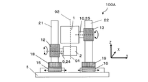
- FIGS. 1 and 2 are schematic side views of the image evaluation apparatus 100A.
- a video evaluation apparatus 100A shown in FIG. 1 is an apparatus for evaluating a video (aerial video) 4 imaged in the air by the reflective imaging element 1.
- the image evaluation apparatus 100A includes a first support portion 9 that supports a display panel (for example, a liquid crystal display panel) 2 having a display surface 2a that forms an image, and a reflective imaging element 1 that defines an imaging symmetry plane 1a. It has the 2nd support part 10 which supports, and the 3rd support part 11 which supports the light receiver 3 which has the light-receiving surface 3a. Furthermore, the image evaluation apparatus 100A has a holding mechanism (in the present embodiment, the first holding mechanism 12 and the second holding mechanism) that hold at least one of the first support portion 9 to the third support portion 11 so as to be movable.
- a holding mechanism in the present embodiment, the first holding mechanism 12 and the second holding mechanism
- the image evaluation apparatus 100A is emitted from the display surface 2a of the display panel 2, and is formed on the image formation surface 4a at a position symmetrical with respect to the display surface 2a with the image formation symmetry surface 1a of the reflective image formation element 1 as a symmetry surface.
- the light constituting the imaged aerial image 4 is received by the light receiving surface 3a of the light receiver 3, and the optical evaluation of the aerial image can be performed quantitatively.
- the imaging symmetry plane 1a refers to a virtual mirror surface (corresponding to a plane-symmetric symmetry plane) that forms an image displayed on the display surface 2a at a position symmetrical with respect to the display surface 2a.
- the light receiving surface 3a of the light receiver 3 is, for example, the outermost surface of a lens included in the light receiver 3.
- the video evaluation apparatus 100 ⁇ / b> A is based on the positional information on the display surface 2 a of the display panel 2 and the positional information on the imaging symmetric surface 1 a of the reflective imaging element 1.
- a calculation unit 50 for obtaining position information is further included.
- the light receiving surface of the light receiver 3 is calculated by the calculation unit 50 based on, for example, the positional information of the display surface 2a of the display panel 2 and the positional information of the imaging symmetry plane 1a of the reflective imaging element 1.
- the arrangement position of 3a is calculated, and the third support portion 11 moves based on the calculated result.
- the video evaluation apparatus 100 ⁇ / b> A includes a horizontal base 5, and includes a first vertical pillar 21, a second vertical pillar 22, and a third vertical pillar 23 arranged on the horizontal base 5. Furthermore, the image evaluation apparatus 100A includes a first moving mechanism 15 attached to the first vertical pillar 21, a second moving mechanism 16 attached to the second vertical pillar 22, and a third attached to the third vertical pillar 23. A moving mechanism 17 is provided. The first moving mechanism 15, the second moving mechanism 16, and the third moving mechanism 17 move independently, for example, in the Y direction shown in FIG. Further, a fourth moving mechanism 18 is disposed on the first moving mechanism 15, a fifth moving mechanism 19 is disposed on the second moving mechanism 16, and a sixth moving mechanism 20 is disposed on the third moving mechanism 17.
- the fourth moving mechanism 18, the fifth moving mechanism 19, and the sixth moving mechanism 20 move independently in the X direction shown in FIG.
- the fourth moving mechanism 18 is attached to the first vertical pillar 21, the fifth moving mechanism 19 is attached to the second vertical pillar 22, and the sixth moving mechanism 20 is attached to the third vertical pillar 23.
- the first holding mechanism 12, the second holding mechanism 13, and the third holding mechanism 14 are attached to the corresponding first vertical column 21, second vertical column 22, and third vertical column 23 so as to be movable.
- At least one of the first holding mechanism 12, the second holding mechanism 13, and the third holding mechanism 14 has a rotation mechanism (rotation mechanisms 24 to 26 in the image evaluation apparatus 100A).
- the display panel 2, the reflective imaging element 1 or the light receiver 3 can be independently rotated so that the normal line of the image plane 4a and the normal line of the light receiving surface 3a are parallel to each other. With such a rotation mechanism, for example, the viewing angle characteristics of the aerial image 4 can be evaluated.
- FIG. 2 is a schematic side view of the image evaluation apparatus 100A when viewed from the X direction of FIG. However, FIG. 2 does not show the light receiver 3 and the components related to the light receiver 3 (such as the third holding mechanism 14).
- the first support portion 9 is attached to the first rotation mechanism 24, and the second support portion 10 is attached to the second rotation mechanism 25, and by these rotation mechanisms 24 and 25,
- the display panel 2 and the reflective imaging element 1 supported by the corresponding support portions 9 and 10 can rotate independently about the Y direction shown in FIG.
- the display panel 2 and the reflective imaging element 1 can be independently moved in the Y direction shown in FIG. 2 by the first moving mechanism 15 and the second moving mechanism 16, for example.
- the aerial image 4 is evaluated, the length of the display surface 2a of the display panel 2 in the Y direction is divided into two equal parts, and the axis 91 extending in the Z direction in FIG.
- the display panel 2 and the reflective imaging element 1 may be arranged so that the length is divided into two and the axis 92 extending in the Z direction in FIG.
- the display panel 2 and the reflection type imaging element 1 are arranged in this way, a large amount of light emitted from the display surface 2a of the display panel 2 is incident on the reflection type imaging element 1, which is desirable as an evaluation target.
- the aerial image can be evaluated if the display surface 2 a of the display panel 2 and the reflective imaging element 1 overlap in the Y direction. It is.
- FIG. 3 (a) and 3 (b) are schematic plan views of the holders 31 and 32, respectively, and FIGS. 3 (c) and 3 (d) are schematic views of the holders 31 and 32, respectively.
- FIG. 3 (c) and 3 (d) are schematic views of the holders 31 and 32, respectively.
- the display panel 2 and the reflective imaging element 1 are independently held by holders 31 and 32 and connected to corresponding holding mechanisms 12 and 13, respectively. It is preferred that The holders 31 and 32 can prevent the display panel 2 and the reflective imaging element 1 from being bent.
- the holder 32 is preferably provided with an opening 33. When a wiring (for example, a power supply wiring) connected to the display panel 2 is drawn downward (toward the horizontal base 5) from the opening 33, the light from the display panel 2 is not blocked by the wiring. Note that when there is no wiring connecting the display panel 2 and an external circuit, the opening 33 may not be provided.
- the reflective imaging element 1 is a reflective imaging element disclosed in Patent Document 1, for example.
- the display panel 2 is, for example, a liquid crystal display panel.
- a display panel such as an organic EL (Electro Luminescence) display panel or a plasma display can be used.
- the light receiver 3 is, for example, a luminance meter.
- a luminance meter When a luminance meter is used, the luminance of the aerial image is measured.
- a luminance meter a color luminance meter, a spectral radiance meter, or EZContrast (manufactured by ELDIM, disclosed in US Pat. No. 6,804,001) is used.
- the six moving mechanism 20 has, for example, an automatic stage driven by a stepping motor, and a control circuit (not shown) has a first holding mechanism 12, a second holding mechanism 13, a third holding mechanism 14, a first moving mechanism 15, and a second moving mechanism 20.
- the moving mechanism 16, the third moving mechanism 17, the fourth moving mechanism 18, the fifth moving mechanism 19, and the sixth moving mechanism 20 are independently controlled.
- the first rotation mechanism 24, the second rotation mechanism 25, and the third rotation mechanism 26 have, for example, an automatic rotation stage driven by a stepping motor, and a control circuit (not shown) has the first rotation mechanism 24 and the second rotation mechanism 25. , And the third rotation mechanism 26 are independently controlled.
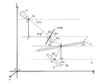
- FIG. 4 is a diagram for explaining the positional relationship among the reflective imaging element 1 (imaging symmetry plane 1a), the display panel 2 (display surface 2a), and the light receiver 3 (light receiving surface 3a).
- the calculation unit 50 in the image evaluation apparatus 100A calculates the position information of the light receiver 3 from the position information of the reflective imaging element 1 and the position information of the display panel 2 by calculation. Note that the angles ⁇ 1 to ⁇ 4 , the angle ⁇ 3 ′, the angle ⁇ 7 , and the angles ⁇ 9 to ⁇ 11 shown in FIG. 4 are each based on the horizontal plane (broken line in the figure).
- angles ⁇ 1 to ⁇ 4 , the angle ⁇ 3 ′, the angle ⁇ 7 , and the angles ⁇ 9 to ⁇ 11 have a positive direction counterclockwise and a negative direction clockwise with respect to the horizontal plane.
- the point A shown in FIG. 4 is a point on the imaging symmetry plane 1a of the reflective imaging element 1
- the point B is a point on the display surface 2a of the display panel 2
- the point C is This is a point on the image plane 4a of the aerial image 4.
- the optical characteristics (for example, luminance) of the aerial image from the direction inclined by the angle ⁇ 3 with respect to the imaging plane 4a of the aerial image 4 are evaluated.
- the angle ⁇ 3 is equal to the angle ⁇ 3 ′ formed by the direction of light emitted from the display panel 2 and the display surface 2a of the display panel 2 due to the characteristics of the reflective imaging element 1 (see FIG. 4).
- the angles formed by the horizontal plane and the reflective imaging element 1 and the display surface 2a of the display panel 2 are defined as an angle ⁇ 1 and an angle ⁇ 2 , respectively.
- the coordinates (Xa, Ya, Za) of the point A, the coordinates (Xb, Yb, Zb) of the point B, the inclination angle ⁇ 1 of the reflective imaging element 1, the inclination angle ⁇ 2 of the display panel 2 , and the angle ⁇ 3, is set in accordance with the configuration of the optical system to be evaluated.
- the coordinates of the set points A and B, and information on the angle ⁇ 1 , the angle ⁇ 2, and the angle ⁇ 3 are sent to the calculation unit (electronic computer or the like) 50.
- the reflective imaging element 1 Since the reflective imaging element 1 has the property of forming an image at a plane-symmetrical position, the angle formed by the display surface 2a of the display panel 2 and the imaging symmetric surface 1a of the reflective imaging element 1 and the imaging plane The angle formed by 4a and the imaging symmetry plane 1a of the reflective imaging element 1 is equal, and the angle ⁇ 4 satisfies the following formula (1).
- an intersection point between a straight line perpendicular to the point A and a horizontal plane including the point B is defined as a point G.
- the length d 1 of the line segment BA satisfies the following formula (2).
- d 2 is the length of the line segment AC
- angle ⁇ 7 is an angle formed by the line segment CE and the line segment CA.
- the angle ⁇ 9 is an angle formed by the horizontal plane and the line segment CA
- the angle ⁇ 10 is an angle formed by the horizontal plane and the optical axis of the light receiver 3.
- the position of the light receiver 3 for measuring the optical characteristics (for example, luminance) from the direction inclined by the angle ⁇ 3 with respect to the imaging surface 4a is obtained by calculation. Specifically, the coordinates (Xd, Yd, Zd) of the point D on the optical axis of the light receiver 3 and the installation angle ⁇ 11 of the light receiver 3 are obtained.
- Xd Xa ⁇ d 1 ⁇ sin ( ⁇ 3 + 2 ⁇ 1 ⁇ 2 ⁇ 90 °) ⁇ d 3 ⁇ cos ⁇ 180 ° ⁇ ( ⁇ 3 + 2 ⁇ 1 ⁇ 2 ) ⁇
- the optical characteristics of the aerial image 4 from the angle ⁇ 3 with respect to the imaging plane 4a can be obtained by moving the light receiver 3 accordingly. Can be evaluated.
- the optical characteristics of the aerial image 4 in the normal direction of the image plane 4a of the aerial image 4 can be evaluated.
- FIG. 5 is a schematic side view of the video evaluation apparatus 100B.
- FIG. 6A and FIG. 6B are diagrams for explaining the optical characteristics of the aerial image 4.
- FIG. 7 is a diagram for explaining the positional relationship among the reflective imaging element 1, the display panel 2, and the light receiver 3.
- the video evaluation apparatus 100B does not include the third holding mechanism 14, the third movement mechanism 17, the sixth movement mechanism 20, and the rotation mechanism 26 that the video evaluation apparatus 100A has. Therefore, the arrangement position of the light receiver 3 is fixed. Further, the target of calculation performed by the calculation unit 50 in the video evaluation apparatus 100B is different from the target of calculation performed by the calculation unit 50 in the video evaluation apparatus 100A. Specifically, in the video evaluation apparatus 100A, the calculation unit 50 calculates the position information of the light receiver 3 from the relative position information of the reflective imaging element 1 and the display panel 2 by calculation.
- the calculation unit 50 in the image evaluation apparatus 100B calculates the position information of the imaging surface 4a based on the position information of the light receiving surface 3a of the light receiver 3, and further, based on the result, the reflective imaging element 1 and the display The position information of each panel 2 is calculated.
- the first and second support portions 9 and 10 can be moved in accordance with the calculated positional information of the reflective imaging element 1 and the display panel 2.
- an angle formed between the reflective imaging element 1 and the horizontal plane is an angle ⁇ 1
- an angle formed between the display panel 2 and the horizontal plane is an angle ⁇ 2 .
- a point A is defined as an intersection point between a straight line extending perpendicularly from the point B on the display surface 2 a of the display panel 2 and the imaging symmetry plane 1 a of the reflective imaging element 1.
- the optical characteristics (for example, luminance or contrast ratio) of the aerial image 4 that is imaged in the air via the reflective imaging element 1 is a relative positional relationship between the reflective imaging element 1 and the display panel 2. That is, it is determined by the length of the line segment AB and the angle difference ( ⁇ 1 ⁇ 2 ). Therefore, the measurement results of the optical characteristics of the aerial image 4 shown in FIG. 6A and the measurement results of the optical characteristics of the aerial image 4 shown in FIG. 6B are the same in principle.
- the video evaluation apparatus 100B utilizes such characteristics.
- the arrangement position of the light receiver 3 is determined.
- the angle ⁇ 11 with respect to the coordinates (Xd, Yd, Zd) of the point D on the optical axis of the light receiver 3 and the horizontal plane (broken line) is determined.
- the point D may be the focal point of the objective lens of the light receiver 3.
- the aerial image 4 is evaluated from a direction inclined at an angle ⁇ 3 with respect to the imaging plane 4a.
- the distance d 3 between the point C and the point D on the image plane 4a is determined by the type of the light receiver 3 and the setting conditions.
- the coordinates (Xc, Yc, Zc) of the point C on the image plane 4a are obtained by geometric calculation as follows.
- the arrangement positions of the reflective imaging element 1 and the display panel 2 (the coordinates of the points A and B, the angle ⁇ 1 , the angle ⁇ 1 , so as to match the position (point C) of the imaging plane 4a obtained above.
- the angle ⁇ 2 the arrangement positions of the reflective imaging element 1 and the display panel 2 (the coordinates of the points A and B, the angle ⁇ 1 , the angle ⁇ 1 , so as to match the position (point C) of the imaging plane 4a obtained above.
- the angle ⁇ 2 the arrangement positions of the reflective imaging element 1 and the display panel 2 (the coordinates of the points A and B, the angle ⁇ 1 , the angle ⁇ 1 , so as to match the position (point C) of the imaging plane 4a obtained above.
- the angle ⁇ 2
- ⁇ 4 180 ° ⁇ 11 ⁇ 3
- the reflective imaging element 1 has a characteristic of imaging at a plane-symmetrical position, so that the length of the line segment AC is equal to the length (d 1 ) of the line segment AB.
- the coordinates (Xa, Ya, Za) of the point A on the imaging symmetry plane 1a of the reflective imaging element 1 are obtained by geometric calculation as follows.
- a point G is defined as an intersection of a straight line perpendicular to the point A and a horizontal plane including the point B.
- Za ⁇ d 1 ⁇ sin ⁇ 12 Zd ⁇ (d 3 + d 1 ) sin ⁇ 11 ⁇ d 1 ⁇ sin ( ⁇ 11 + 2 ⁇ ⁇ )
- the position information of the reflective imaging device 1 (coordinates and angle theta 1 of point A), and the position information of the display panel 2 (coordinates and angle theta 2 of the point B) is obtained.
- the optical characteristics of the aerial image 4 may be measured.
- the optical characteristics of the aerial image 4 in the normal direction of the image plane 4a of the aerial image 4 can be evaluated. Since the video evaluation apparatus 100B does not have a mechanism for moving the light receiver 3, there is an advantage that the video evaluation apparatus 100B can be manufactured at low cost.
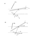
- FIG. 8 (a) and 8 (b) show the reflective imaging element 1 (symmetrical imaging plane 1a) and display panel 2 (when the luminance measurement of the aerial video 4 is performed using the video evaluation apparatus 100A. It is a figure explaining the arrangement
- VA Vertical Alignment
- the installation angle of the liquid crystal display panel 2c is 60 °.
- the reflective imaging element 1 is disposed so as to be parallel to the horizontal plane (broken line).
- Point A is a point where a line extending in the normal direction from the center point B of the display surface 2a of the liquid crystal display panel 2c and the imaging symmetry plane 1a of the reflective imaging element 1 intersect.
- the distance between the points AB (the length of the line segment AB) is set to 90 mm, the coordinates of the point B are (0, 0, 0), and the coordinates of the point A are (45 ⁇ 3, 0, 45) ( (The unit of each coordinate is mm.)
- An intersection point between a line extending in the direction of 85 ° with respect to the display surface 2a from the center point B of the display surface 2a of the liquid crystal display panel 2c and the imaging symmetry plane 1a of the reflective imaging element 1 is a point E (the point E is For example, the distance between the points BE is set to 90 mm, the coordinates of the point B are (0, 0, 0), and the coordinates of the point E are (90 ⁇ cos 35 °, 0, 90 ⁇ ). sin 35 °).
- the brightness of the aerial image 4 measured from the normal direction of the image plane 4a of the aerial image 4 and the direction inclined by 5 ° from the normal direction of the image plane 4a of the aerial image 4 When compared with the luminance of the video 4, there is a difference in luminance of about 10%, and it can be seen that the measurement of the luminance of the aerial video 4 varies if the luminance meter 3 c is not accurately installed.
- an image evaluation apparatus capable of quantitatively evaluating an aerial image.
- the present invention is widely applied when evaluating an optical system having a reflective imaging element capable of forming an image of a projection object in space and a display panel.
Abstract
The aerial image evaluation apparatus (100A) according to an embodiment of the present invention is an apparatus for evaluating images formed in the air by a reflective image-forming element (1), and comprises: a first support part (9) which supports a display panel (2) having a display surface (2a) for forming images; a second support part (10) which supports the reflective image-forming element (1) that defines an image-forming symmetrical plane (1a); a third support part (11) which supports a photoreceiver (3) having a light-receiving surface (3a); and holding mechanisms (12 to 14) that hold at least one of the support parts among the first to third support parts (9 and 10) in a movable manner, such that light is emitted from the display surface (2a) of the display panel (2), and, with the image-forming symmetrical plane (1a) of the reflective image-forming element (1) as a symmetrical plane, light constituting an aerial image (4), which is formed on an image-forming plane (4a) at a surface symmetrical position with respect to the display surface (2a), is received by the light-receiving surface (3a).
Description
本発明は、空中映像を評価する空中映像評価装置に関する。
The present invention relates to an aerial video evaluation apparatus for evaluating an aerial video.
最近、反射型結像素子を用いて空間に被投影物を結像させる光学システムが提案されている(例えば、特許文献1~3)。光学システムは反射型結像素子と被投影物とを有し、空間に表示される像(以下、「空中映像」という。)は、反射型結像素子を対称面とする面対称な位置に、被投影物の像が結像したものである。この光学システムは、反射型結像素子の鏡面反射を利用しており、原理上、被投影物の像と空間に映し出される像との大きさの比は、1:1である。
Recently, an optical system that forms an image of a projection object in a space using a reflective imaging element has been proposed (for example, Patent Documents 1 to 3). The optical system has a reflective imaging element and a projection, and an image displayed in space (hereinafter referred to as “aerial image”) is in a plane-symmetric position with the reflective imaging element as a symmetry plane. The image of the projection object is formed. This optical system uses specular reflection of a reflective imaging element, and in principle, the ratio of the size of the image of the projection object and the image projected in space is 1: 1.
反射型結像素子としては、平板状の基板の厚さ方向に貫通させた複数の穴を備え、各穴の内壁に直交する2つの鏡面要素から構成される光学素子を有するもの(例えば、特許文献1の図4参照)、あるいは基板の厚さ方向に突出させた複数の透明な筒状体を備え、各筒状体の内壁面に直交する2つの鏡面要素から構成される光学素子を有するものが開示されている(例えば、特許文献1の図7参照)。
The reflective imaging element includes an optical element that includes a plurality of holes penetrating in the thickness direction of a flat substrate and includes two mirror elements perpendicular to the inner wall of each hole (for example, a patent) 4) or a plurality of transparent cylindrical bodies protruding in the thickness direction of the substrate, and an optical element composed of two mirror elements perpendicular to the inner wall surface of each cylindrical body. (For example, refer to FIG. 7 of Patent Document 1).
特許文献1に開示されている反射型結像素子は、厚さが50μm~200μmの基板に、一辺が約50μm~200μmの正方形の穴が数万から数十万個形成されており、各穴の内面には、電鋳法、ナノプリント法やスパッタ法によって鏡面コーティングが施されている。
The reflective imaging element disclosed in Patent Document 1 has tens of thousands to hundreds of thousands of square holes each having a side of about 50 μm to 200 μm formed on a substrate having a thickness of 50 μm to 200 μm. The inner surface is mirror-coated by electroforming, nanoprinting or sputtering.
参考のために、特許文献1から3の開示内容の全てを本明細書に援用する。
For the purpose of reference, the entire disclosure of Patent Documents 1 to 3 is incorporated herein by reference.
本発明者は、上記光学システムについて様々な検討を行っている。これまで、本発明者は、空中映像の表示品位を、主に目視で評価しており、定量的な評価を行っていなかった。これは、空中映像は無体物であり、空中映像の位置を特定しにくく、空中映像を基準として所望の位置に測定装置を配置することが困難だからである。
The present inventor has made various studies on the optical system. Until now, the present inventor has mainly evaluated the display quality of aerial images visually, and has not performed a quantitative evaluation. This is because the aerial image is intangible, it is difficult to specify the position of the aerial image, and it is difficult to place the measuring device at a desired position with reference to the aerial image.
本発明は、上記問題に鑑みてなされたものであり、その目的は、空中映像の評価を定量的に行える空中映像評価装置を提供することにある。
The present invention has been made in view of the above problems, and an object thereof is to provide an aerial image evaluation apparatus capable of quantitatively evaluating an aerial image.
本発明による実施形態における空中映像評価装置は、反射型結像素子によって空中に結像された映像を評価する装置であって、映像を形成する表示面を有する表示パネルを支持する第1支持部と、結像対称面を規定する反射型結像素子を支持する第2支持部と、受光面を有する受光器を支持する第3支持部と、前記表示パネルの前記表示面から出射され、前記反射型結像素子の前記結像対称面を対称面として、前記表示面に対して面対称な位置の結像面に結像された空中映像を構成する光を、前記受光面で受光するように、前記第1から第3支持部の内の少なくとも1つの支持部を移動可能に保持する保持機構とを有する。
An aerial image evaluation apparatus according to an embodiment of the present invention is an apparatus that evaluates an image formed in the air by a reflective imaging element, and that supports a display panel having a display surface that forms an image. A second support part that supports a reflective imaging element that defines an imaging symmetry plane, a third support part that supports a light receiver having a light receiving surface, and the light emitted from the display surface of the display panel, The light-receiving surface receives the light constituting the aerial image formed on the imaging plane at a plane symmetric with respect to the display plane, with the imaging symmetry plane of the reflective imaging element as the symmetry plane. And a holding mechanism for movably holding at least one of the first to third support portions.
ある実施形態において、前記空中映像評価装置は、前記表示パネルの前記表示面の位置情報と、前記反射型結像素子の前記結像対称面の位置情報とに基づいて、前記結像面の位置情報を求める演算部をさらに有し、前記保持機構は、前記結像面の前記位置情報に応じて、前記第3支持部を移動させることができる。
In one embodiment, the aerial image evaluation device is configured to determine the position of the imaging plane based on positional information of the display surface of the display panel and positional information of the imaging symmetry plane of the reflective imaging element. The information processing apparatus may further include a calculation unit that obtains information, and the holding mechanism may move the third support unit according to the position information of the imaging plane.
ある実施形態において、前記空中映像評価装置は、前記受光器の前記受光面の位置情報に基づいて、前記結像面の位置情報を求める演算部をさらに有し、前記保持機構は、前記結像面の前記位置情報に応じて、前記第1および第2支持部を移動させることができる。
In one embodiment, the aerial image evaluation device further includes a calculation unit that obtains position information of the imaging surface based on position information of the light receiving surface of the light receiver, and the holding mechanism includes the imaging The first and second support portions can be moved according to the position information of the surface.
ある実施形態において、前記保持機構は、前記結像面の法線と、前記受光面の法線とが互いに平行になるように、前記表示面、前記結像対称面、および前記受光面の内の少なくとも1つを回転させることができる。
In one embodiment, the holding mechanism includes the display surface, the imaging symmetry surface, and the light receiving surface so that a normal line of the imaging surface and a normal line of the light receiving surface are parallel to each other. At least one of the can be rotated.
本発明の実施形態により、空中映像の評価を定量的に行える空中映像評価装置が提供される。
The embodiment of the present invention provides an aerial image evaluation apparatus capable of quantitatively evaluating an aerial image.
以下、図面を参照して本発明の実施形態を説明するが、本発明は例示する実施形態に限定されない。
Hereinafter, embodiments of the present invention will be described with reference to the drawings, but the present invention is not limited to the illustrated embodiments.
図1および図2を参照して、本発明による実施形態における映像評価装置100Aを説明する。図1および図2は、映像評価装置100Aの模式的な側面図である。
A video evaluation apparatus 100A according to an embodiment of the present invention will be described with reference to FIGS. 1 and 2 are schematic side views of the image evaluation apparatus 100A.
図1に示す映像評価装置100Aは、反射型結像素子1によって空中に結像された映像(空中映像)4を評価する装置である。映像評価装置100Aは、映像を形成する表示面2aを有する表示パネル(例えば、液晶表示パネル)2を支持する第1支持部9と、結像対称面1aを規定する反射型結像素子1を支持する第2支持部10と、受光面3aを有する受光器3を支持する第3支持部11とを有する。さらに、映像評価装置100Aは、第1支持部9から第3支持部11の内の少なくとも1つの支持部を移動可能に保持する保持機構(本実施形態において、第1保持機構12、第2保持機構13、および第3保持機構14)を有する。映像評価装置100Aは、表示パネル2の表示面2aから出射され、反射型結像素子1の結像対称面1aを対称面として、表示面2aに対して面対称な位置の結像面4aに結像された空中映像4を構成する光を、受光器3の受光面3aで受光し、空中映像の光学的な評価を定量的に行える。なお、結像対称面1aとは、表示面2aに表示された映像を表示面2aに対して面対称な位置に結像させる仮想的な鏡面(面対称の対称面に相当する)を指し、典型的には、反射型結像素子1を厚さ方向に二等分する面(中心面)であるが、反射型結像素子1の構造によっては、中心面と一致しないことがある。受光器3の受光面3aとは、例えば、受光器3が有するレンズの最表面である。
A video evaluation apparatus 100A shown in FIG. 1 is an apparatus for evaluating a video (aerial video) 4 imaged in the air by the reflective imaging element 1. The image evaluation apparatus 100A includes a first support portion 9 that supports a display panel (for example, a liquid crystal display panel) 2 having a display surface 2a that forms an image, and a reflective imaging element 1 that defines an imaging symmetry plane 1a. It has the 2nd support part 10 which supports, and the 3rd support part 11 which supports the light receiver 3 which has the light-receiving surface 3a. Furthermore, the image evaluation apparatus 100A has a holding mechanism (in the present embodiment, the first holding mechanism 12 and the second holding mechanism) that hold at least one of the first support portion 9 to the third support portion 11 so as to be movable. It has a mechanism 13 and a third holding mechanism 14). The image evaluation apparatus 100A is emitted from the display surface 2a of the display panel 2, and is formed on the image formation surface 4a at a position symmetrical with respect to the display surface 2a with the image formation symmetry surface 1a of the reflective image formation element 1 as a symmetry surface. The light constituting the imaged aerial image 4 is received by the light receiving surface 3a of the light receiver 3, and the optical evaluation of the aerial image can be performed quantitatively. The imaging symmetry plane 1a refers to a virtual mirror surface (corresponding to a plane-symmetric symmetry plane) that forms an image displayed on the display surface 2a at a position symmetrical with respect to the display surface 2a. Typically, it is a plane (center plane) that bisects the reflective imaging element 1 in the thickness direction, but may not coincide with the central plane depending on the structure of the reflective imaging element 1. The light receiving surface 3a of the light receiver 3 is, for example, the outermost surface of a lens included in the light receiver 3.
図1に示すように、映像評価装置100Aは、表示パネル2の表示面2aの位置情報と、反射型結像素子1の結像対称面1aの位置情報とに基づいて、結像面4aの位置情報を求める演算部50をさらに有する。詳細は後述するが、演算部50により、例えば、表示パネル2の表示面2aの位置情報、および反射型結像素子1の結像対称面1aの位置情報に基づいて、受光器3の受光面3aの配置位置が算出され、算出された結果に基づいて第3支持部11が移動する。
As shown in FIG. 1, the video evaluation apparatus 100 </ b> A is based on the positional information on the display surface 2 a of the display panel 2 and the positional information on the imaging symmetric surface 1 a of the reflective imaging element 1. A calculation unit 50 for obtaining position information is further included. Although details will be described later, the light receiving surface of the light receiver 3 is calculated by the calculation unit 50 based on, for example, the positional information of the display surface 2a of the display panel 2 and the positional information of the imaging symmetry plane 1a of the reflective imaging element 1. The arrangement position of 3a is calculated, and the third support portion 11 moves based on the calculated result.
図1に示すように、映像評価装置100Aは、水平台5を有し、水平台5上に配置された、第1垂直柱21、第2垂直柱22、および第3垂直柱23を有する。さらに、映像評価装置100Aは、第1垂直柱21に取り付けられた第1移動機構15、第2垂直柱22に取り付けられた第2移動機構16、および第3垂直柱23に取り付けられた第3移動機構17を有する。第1移動機構15、第2移動機構16および第3移動機構17は、例えば図1に示すY方向にそれぞれ独立に移動する。さらに、第1移動機構15上には第4移動機構18が配置され、第2移動機構16上には第5移動機構19が配置され、第3移動機構17上には第6移動機構20が配置されている。第4移動機構18、第5移動機構19、および第6移動機構20は、例えば図1に示すX方向にそれぞれ独立に移動する。第4移動機構18は第1垂直柱21に取り付けられ、第5移動機構19は第2垂直柱22に取り付けられ、第6移動機構20は第3垂直柱23に取り付けられている。第1保持機構12、第2保持機構13、および第3保持機構14はそれぞれ、対応する第1垂直柱21、第2垂直柱22および第3垂直柱23に移動可能なように取り付けられており、対応する第1垂直柱21、第2垂直柱22および第3垂直柱23に沿って、例えば図1に示すZ方向にそれぞれ独立に移動する。さらに、第1保持機構12、第2保持機構13、および第3保持機構14の少なくとも1つの保持機構は回転機構(映像評価装置100Aにおいては、回転機構24から26)を有し、例えば、結像面4aの法線と、受光面3aの法線とが互いに平行になるように表示パネル2、反射型結像素子1または受光器3をそれぞれ独立に回転させることができる。このような、回転機構を有すると、例えば、空中映像4の視野角特性の評価が可能となる。
As shown in FIG. 1, the video evaluation apparatus 100 </ b> A includes a horizontal base 5, and includes a first vertical pillar 21, a second vertical pillar 22, and a third vertical pillar 23 arranged on the horizontal base 5. Furthermore, the image evaluation apparatus 100A includes a first moving mechanism 15 attached to the first vertical pillar 21, a second moving mechanism 16 attached to the second vertical pillar 22, and a third attached to the third vertical pillar 23. A moving mechanism 17 is provided. The first moving mechanism 15, the second moving mechanism 16, and the third moving mechanism 17 move independently, for example, in the Y direction shown in FIG. Further, a fourth moving mechanism 18 is disposed on the first moving mechanism 15, a fifth moving mechanism 19 is disposed on the second moving mechanism 16, and a sixth moving mechanism 20 is disposed on the third moving mechanism 17. Has been placed. For example, the fourth moving mechanism 18, the fifth moving mechanism 19, and the sixth moving mechanism 20 move independently in the X direction shown in FIG. The fourth moving mechanism 18 is attached to the first vertical pillar 21, the fifth moving mechanism 19 is attached to the second vertical pillar 22, and the sixth moving mechanism 20 is attached to the third vertical pillar 23. The first holding mechanism 12, the second holding mechanism 13, and the third holding mechanism 14 are attached to the corresponding first vertical column 21, second vertical column 22, and third vertical column 23 so as to be movable. , Move independently along the corresponding first vertical column 21, second vertical column 22 and third vertical column 23, for example, in the Z direction shown in FIG. Furthermore, at least one of the first holding mechanism 12, the second holding mechanism 13, and the third holding mechanism 14 has a rotation mechanism (rotation mechanisms 24 to 26 in the image evaluation apparatus 100A). The display panel 2, the reflective imaging element 1 or the light receiver 3 can be independently rotated so that the normal line of the image plane 4a and the normal line of the light receiving surface 3a are parallel to each other. With such a rotation mechanism, for example, the viewing angle characteristics of the aerial image 4 can be evaluated.
図2は、図1のX方向から見たときの映像評価装置100Aの模式的な側面図である。ただし、図2には、受光器3および受光器3に関連する構成要素(第3保持機構14など)は示していない。
FIG. 2 is a schematic side view of the image evaluation apparatus 100A when viewed from the X direction of FIG. However, FIG. 2 does not show the light receiver 3 and the components related to the light receiver 3 (such as the third holding mechanism 14).
図2に示すように、第1支持部9は第1回転機構24に取り付けられており、第2支持部10は第2回転機構25に取り付けられており、これらの回転機構24および25により、それぞれ対応する支持部9および10に支持された表示パネル2および反射型結像素子1が、例えば、図2に示すY方向を軸としてそれぞれ独立に回転できる。さらに、第1移動機構15および第2移動機構16により、表示パネル2および反射型結像素子1は、例えば、図2に示すY方向にそれぞれ独立に移動できる。空中映像4を評価する際には、表示パネル2の表示面2aのY方向の長さを2等分し図2のZ方向に伸びる軸91と、反射型結像素子1のY方向の長さを2等分し図2のZ方向に伸びる軸92とが一致するように表示パネル2と反射型結像素子1とを配置するとよい。このように表示パネル2および反射型結像素子1を配置すると、表示パネル2の表示面2aから発せられた光が反射型結像素子1に多く入射するので、評価する対象として望ましいからである。ただし、このような表示パネル2および反射型結像素子1の配置以外でも、Y方向において表示パネル2の表示面2aと反射型結像素子1とが重なっていれば、空中映像の評価は可能である。
As shown in FIG. 2, the first support portion 9 is attached to the first rotation mechanism 24, and the second support portion 10 is attached to the second rotation mechanism 25, and by these rotation mechanisms 24 and 25, For example, the display panel 2 and the reflective imaging element 1 supported by the corresponding support portions 9 and 10 can rotate independently about the Y direction shown in FIG. Further, the display panel 2 and the reflective imaging element 1 can be independently moved in the Y direction shown in FIG. 2 by the first moving mechanism 15 and the second moving mechanism 16, for example. When the aerial image 4 is evaluated, the length of the display surface 2a of the display panel 2 in the Y direction is divided into two equal parts, and the axis 91 extending in the Z direction in FIG. The display panel 2 and the reflective imaging element 1 may be arranged so that the length is divided into two and the axis 92 extending in the Z direction in FIG. When the display panel 2 and the reflection type imaging element 1 are arranged in this way, a large amount of light emitted from the display surface 2a of the display panel 2 is incident on the reflection type imaging element 1, which is desirable as an evaluation target. . However, in addition to the arrangement of the display panel 2 and the reflective imaging element 1, the aerial image can be evaluated if the display surface 2 a of the display panel 2 and the reflective imaging element 1 overlap in the Y direction. It is.
次に、保持具31、32について図3を参照しながら説明する。図3(a)および図3(b)はそれぞれ、保持具31、32の模式的な平面図であり、図3(c)および図3(d)はそれぞれ、保持具31、32の模式的な側面図である。
Next, the holders 31 and 32 will be described with reference to FIG. 3 (a) and 3 (b) are schematic plan views of the holders 31 and 32, respectively, and FIGS. 3 (c) and 3 (d) are schematic views of the holders 31 and 32, respectively. FIG.
図3(a)~図3(d)に示すように、表示パネル2と反射型結像素子1とは、それぞれ独立に保持具31、32に保持されて対応する保持機構12、13と接続されることが好ましい。保持具31、32により、表示パネル2および反射型結像素子1がたわむことを防ぐことができる。保持具32には、開口部33を設けることが好ましい。この開口部33から表示パネル2に接続されている配線(例えば、電源用配線)を下方向(水平台5側方向)へ引き出すと、表示パネル2からの光が配線により遮られなくなる。なお、表示パネル2と外部回路などとを接続する配線がない場合、開口部33は設けなくてもよい。
As shown in FIGS. 3 (a) to 3 (d), the display panel 2 and the reflective imaging element 1 are independently held by holders 31 and 32 and connected to corresponding holding mechanisms 12 and 13, respectively. It is preferred that The holders 31 and 32 can prevent the display panel 2 and the reflective imaging element 1 from being bent. The holder 32 is preferably provided with an opening 33. When a wiring (for example, a power supply wiring) connected to the display panel 2 is drawn downward (toward the horizontal base 5) from the opening 33, the light from the display panel 2 is not blocked by the wiring. Note that when there is no wiring connecting the display panel 2 and an external circuit, the opening 33 may not be provided.
反射型結像素子1は、例えば特許文献1に開示されている反射型結像素子である。
The reflective imaging element 1 is a reflective imaging element disclosed in Patent Document 1, for example.
表示パネル2は、例えば液晶表示パネルである。また、液晶表示パネルの代わりに、有機EL(Electro Luminescence)表示パネルやプラズマディスプレイなどの表示パネルを用いることもできる。また、国際公開第2011/052588号に開示されているファイバーフェイスプレートを備える表示パネルを用いてもよい。
The display panel 2 is, for example, a liquid crystal display panel. Instead of the liquid crystal display panel, a display panel such as an organic EL (Electro Luminescence) display panel or a plasma display can be used. Moreover, you may use the display panel provided with the fiber face plate currently disclosed by international publication 2011/052588.
受光器3は、例えば輝度計である。輝度計を用いた場合、空中映像の輝度が測定される。輝度計として、色彩輝度計、分光放射輝度計、またはEZContrast(ELDIM社製、米国特許6804001号明細書に開示されている。)が用いられる。
The light receiver 3 is, for example, a luminance meter. When a luminance meter is used, the luminance of the aerial image is measured. As the luminance meter, a color luminance meter, a spectral radiance meter, or EZContrast (manufactured by ELDIM, disclosed in US Pat. No. 6,804,001) is used.
第1保持機構12、第2保持機構13、第3保持機構14、第1移動機構15、第2移動機構16、第3移動機構17、第4移動機構18、第5移動機構19、および第6移動機構20は、例えば、ステッピングモーター駆動による自動ステージを有し、不図示の制御回路が第1保持機構12、第2保持機構13、第3保持機構14、第1移動機構15、第2移動機構16、第3移動機構17、第4移動機構18、第5移動機構19、および第6移動機構20をそれぞれ独立に制御している。
The first holding mechanism 12, the second holding mechanism 13, the third holding mechanism 14, the first moving mechanism 15, the second moving mechanism 16, the third moving mechanism 17, the fourth moving mechanism 18, the fifth moving mechanism 19, and the first The six moving mechanism 20 has, for example, an automatic stage driven by a stepping motor, and a control circuit (not shown) has a first holding mechanism 12, a second holding mechanism 13, a third holding mechanism 14, a first moving mechanism 15, and a second moving mechanism 20. The moving mechanism 16, the third moving mechanism 17, the fourth moving mechanism 18, the fifth moving mechanism 19, and the sixth moving mechanism 20 are independently controlled.
第1回転機構24、第2回転機構25、および第3回転機構26は、例えば、ステッピングモーター駆動による自動回転ステージを有し、不図示の制御回路が第1回転機構24、第2回転機構25、および第3回転機構26をそれぞれ独立に制御している。
The first rotation mechanism 24, the second rotation mechanism 25, and the third rotation mechanism 26 have, for example, an automatic rotation stage driven by a stepping motor, and a control circuit (not shown) has the first rotation mechanism 24 and the second rotation mechanism 25. , And the third rotation mechanism 26 are independently controlled.
次に、図4を参照しながら、演算部50で演算される具体的な内容を説明する。
Next, specific contents calculated by the calculation unit 50 will be described with reference to FIG.
図4は、反射型結像素子1(結像対称面1a)と表示パネル2(表示面2a)と受光器3(受光面3a)との配置関係を説明する図である。映像評価装置100Aにおける演算部50では、反射型結像素子1の位置情報と表示パネル2の位置情報とから受光器3の位置情報を演算によって求める。なお、図4に示されている角度θ1~θ4、角度θ3’、角度θ7、および角度θ9~θ11は、それぞれ水平面(図中の破線)を基準としている。また、角度θ1~θ4、角度θ3’、角度θ7、および角度θ9~θ11は、水平面に対して反時計回りを正の方向とし、時計回りを負の方向としている。さらに、図4に示されている、点Aは反射型結像素子1の結像対称面1a上の点であり、点Bは表示パネル2の表示面2a上の点であり、点Cは空中映像4の結像面4a上の点である。
FIG. 4 is a diagram for explaining the positional relationship among the reflective imaging element 1 (imaging symmetry plane 1a), the display panel 2 (display surface 2a), and the light receiver 3 (light receiving surface 3a). The calculation unit 50 in the image evaluation apparatus 100A calculates the position information of the light receiver 3 from the position information of the reflective imaging element 1 and the position information of the display panel 2 by calculation. Note that the angles θ 1 to θ 4 , the angle θ 3 ′, the angle θ 7 , and the angles θ 9 to θ 11 shown in FIG. 4 are each based on the horizontal plane (broken line in the figure). Further, the angles θ 1 to θ 4 , the angle θ 3 ′, the angle θ 7 , and the angles θ 9 to θ 11 have a positive direction counterclockwise and a negative direction clockwise with respect to the horizontal plane. Furthermore, the point A shown in FIG. 4 is a point on the imaging symmetry plane 1a of the reflective imaging element 1, the point B is a point on the display surface 2a of the display panel 2, and the point C is This is a point on the image plane 4a of the aerial image 4.
空中映像4の結像面4aに対して、角度θ3傾いた方向からの空中映像の光学特性(例えば、輝度)を評価するとする。このとき、反射型結像素子1の特性から、角度θ3は、表示パネル2から出射される光の方向と表示パネル2の表示面2aとのなす角度θ3’と等しい(図4参照)。また、水平面と、反射型結像素子1および表示パネル2の表示面2aとがなす角度をそれぞれ、角度θ1、角度θ2とする。
Assume that the optical characteristics (for example, luminance) of the aerial image from the direction inclined by the angle θ 3 with respect to the imaging plane 4a of the aerial image 4 are evaluated. At this time, the angle θ 3 is equal to the angle θ 3 ′ formed by the direction of light emitted from the display panel 2 and the display surface 2a of the display panel 2 due to the characteristics of the reflective imaging element 1 (see FIG. 4). . The angles formed by the horizontal plane and the reflective imaging element 1 and the display surface 2a of the display panel 2 are defined as an angle θ 1 and an angle θ 2 , respectively.
まず、点Aの座標(Xa,Ya,Za)、点Bの座標(Xb,Yb,Zb)、反射型結像素子1の傾斜角度θ1、表示パネル2の傾斜角度θ2、および角度θ3を、評価したい光学システムの構成にあわせて設定する。
First, the coordinates (Xa, Ya, Za) of the point A, the coordinates (Xb, Yb, Zb) of the point B, the inclination angle θ 1 of the reflective imaging element 1, the inclination angle θ 2 of the display panel 2 , and the angle θ 3, is set in accordance with the configuration of the optical system to be evaluated.
次に、設定された点Aおよび点Bの座標、ならびに角度θ1、角度θ2および角度θ3の情報は、演算部(電子計算機等)50に送られる。
Next, the coordinates of the set points A and B, and information on the angle θ 1 , the angle θ 2, and the angle θ 3 are sent to the calculation unit (electronic computer or the like) 50.
点Bから出射され、点Aに照射され、空中に出射された光と結像面4aとの交点を点C、結像面4aの水平面に対する角度をθ4とすると、点Cの座標および角度θ4は以下のように求められる。
Is emitted from the point B, is irradiated to the point A, a point an intersection point between the light and the image plane 4a emitted into the air C, and the angle and theta 4 with respect to the horizontal plane of the imaging surface 4a, the coordinates and the angle of the point C θ 4 is obtained as follows.
反射型結像素子1が面対称の位置に結像させるという性質を有するので、表示パネル2の表示面2aと反射型結像素子1の結像対称面1aとがなす角度と、結像面4aと反射型結像素子1の結像対称面1aとがなす角度は等しく、角度θ4は、下記式(1)を満たす。
θ4=θ1+(θ1-θ2)=2θ1-θ2 (1) Since thereflective imaging element 1 has the property of forming an image at a plane-symmetrical position, the angle formed by the display surface 2a of the display panel 2 and the imaging symmetric surface 1a of the reflective imaging element 1 and the imaging plane The angle formed by 4a and the imaging symmetry plane 1a of the reflective imaging element 1 is equal, and the angle θ 4 satisfies the following formula (1).
θ 4 = θ 1 + (θ 1 −θ 2 ) = 2θ 1 −θ 2 (1)
θ4=θ1+(θ1-θ2)=2θ1-θ2 (1) Since the
θ 4 = θ 1 + (θ 1 −θ 2 ) = 2θ 1 −θ 2 (1)
次に、点Aから垂直におろした直線と点Bを含む水平面との交点を点Gとする。直角三角形AGBから、線分BAの長さd1は、下記式(2)を満たす。

Next, an intersection point between a straight line perpendicular to the point A and a horizontal plane including the point B is defined as a point G. From the right triangle AGB, the length d 1 of the line segment BA satisfies the following formula (2).
点Cから垂直におろした直線と点Aを含む水平面との交点を点Eとすると、三角形ACEにおいて、幾何計算により、点Cの座標(Xc,Yc,Zc)は、以下のように表される。
Xc=Xa-d2×sinθ7
Yc=Yb
Zc=Za+d2×cosθ7 Assuming that an intersection of a straight line perpendicular to the point C and the horizontal plane including the point A is a point E, the coordinates (Xc, Yc, Zc) of the point C are expressed as follows by geometric calculation in the triangle ACE. The
Xc = Xa−d 2 × sin θ 7
Yc = Yb
Zc = Za + d 2 × cos θ 7
ここで、d2は、線分ACの長さであり、角度θ7は、線分CEと線分CAとのなす角度である。
Here, d 2 is the length of the line segment AC, and the angle θ 7 is an angle formed by the line segment CE and the line segment CA.
反射型結像素子が面対称の位置に結像するという性質を有するので、線分ACの長さ(d2)=線分BAの長さ(d1)を満たす。
Since the reflective imaging element has the property of imaging at a plane-symmetrical position, the length of the line segment AC (d 2 ) = the length of the line segment BA (d 1 ) is satisfied.
さらに、幾何計算により、θ7=90°-θ9、θ9=θ10=180°-(θ3+θ4)、θ4=2θ1-θ2の関係を満たすので、下記式(3)が導かれる。
θ9=θ10=180°-(θ3+2θ1-θ2) (3) Furthermore, since the relationship of θ 7 = 90 ° −θ 9 , θ 9 = θ 10 = 180 ° − (θ 3 + θ 4 ), θ 4 = 2θ 1 −θ 2 is satisfied by geometric calculation, the following equation (3) Is guided.
θ 9 = θ 10 = 180 ° − (θ 3 + 2θ 1 −θ 2 ) (3)
θ9=θ10=180°-(θ3+2θ1-θ2) (3) Furthermore, since the relationship of θ 7 = 90 ° −θ 9 , θ 9 = θ 10 = 180 ° − (θ 3 + θ 4 ), θ 4 = 2θ 1 −θ 2 is satisfied by geometric calculation, the following equation (3) Is guided.
θ 9 = θ 10 = 180 ° − (θ 3 + 2θ 1 −θ 2 ) (3)
ここで、角度θ9は水平面と線分CAとのなす角度であり、角度θ10は水平面と、受光器3の光軸とのなす角度である。
Here, the angle θ 9 is an angle formed by the horizontal plane and the line segment CA, and the angle θ 10 is an angle formed by the horizontal plane and the optical axis of the light receiver 3.
上記式(3)から、角度θ7は、下記式(4)を満たす。
θ7=90°-{180°-(θ3+2θ1-θ2)}=θ3+2θ1-θ2-90° (4) From the above formula (3), the angle θ 7 satisfies the following formula (4).
θ 7 = 90 ° − {180 ° − (θ 3 + 2θ 1 −θ 2 )} = θ 3 + 2θ 1 −θ 2 −90 ° (4)
θ7=90°-{180°-(θ3+2θ1-θ2)}=θ3+2θ1-θ2-90° (4) From the above formula (3), the angle θ 7 satisfies the following formula (4).
θ 7 = 90 ° − {180 ° − (θ 3 + 2θ 1 −θ 2 )} = θ 3 + 2θ 1 −θ 2 −90 ° (4)
従って、点Cの座標(Xc,Yc,Zc)は、以下のように求められる。
Xc=Xa-d1×sin(θ3+2θ1-θ2-90°)
Yc=Yb
Zc=Za+d1×cos(θ3+2θ1-θ2-90°) Therefore, the coordinates (Xc, Yc, Zc) of the point C are obtained as follows.
Xc = Xa−d 1 × sin (θ 3 + 2θ 1 −θ 2 −90 °)
Yc = Yb
Zc = Za + d 1 × cos (θ 3 + 2θ 1 −θ 2 −90 °)
Xc=Xa-d1×sin(θ3+2θ1-θ2-90°)
Yc=Yb
Zc=Za+d1×cos(θ3+2θ1-θ2-90°) Therefore, the coordinates (Xc, Yc, Zc) of the point C are obtained as follows.
Xc = Xa−d 1 × sin (θ 3 + 2θ 1 −θ 2 −90 °)
Yc = Yb
Zc = Za + d 1 × cos (θ 3 + 2θ 1 −θ 2 −90 °)
以上により、結像面4a上の点Cの座標(Xc,Yc,Zc)および角度θ4が求められる。
As described above, the coordinates (Xc, Yc, Zc) and the angle θ 4 of the point C on the image plane 4a are obtained.
次に、結像面4aに対して角度θ3傾いた方向から光学特性(例えば、輝度)を測定するための受光器3の位置を演算にて求める。具体的には、受光器3の光軸上の点Dの座標(Xd,Yd,Zd)および受光器3の設置角度θ11を求める。
Next, the position of the light receiver 3 for measuring the optical characteristics (for example, luminance) from the direction inclined by the angle θ 3 with respect to the imaging surface 4a is obtained by calculation. Specifically, the coordinates (Xd, Yd, Zd) of the point D on the optical axis of the light receiver 3 and the installation angle θ 11 of the light receiver 3 are obtained.
まず、設置角度θ11は、幾何計算より、θ11=θ10=180°-(θ3+2θ1-θ2)を満たす。
First, the installation angle θ 11 satisfies θ 11 = θ 10 = 180 ° − (θ 3 + 2θ 1 −θ 2 ) by geometric calculation.
次に、点Dから垂直におろした直線と点Cを含む水平面との交点をFとすると、三角形DFCにより、
Xd=Xc-d3×cosθ10
Yd=Yc
Zd=Zc+d3×sinθ10
が求められる。ここでd3は、線分CDの長さであり、長さd3は、受光器3の種類および設定条件によって決まる定数である。また、θ10=180°-(θ3+2θ1-θ2)であるので点Dの座標は以下のように求められる。
Xd=Xa-d1×sin(θ3+2θ1-θ2-90°)-d3×cos{180°-(θ3+2θ1-θ2)}
Yd=Yb
Zd=Za+d1×cos(θ3+2θ1-θ2-90°)+d3×sin{180°-(θ3+2θ1-θ2)} Next, let F be the intersection of a straight line perpendicular to point D and the horizontal plane containing point C.
Xd = Xc−d 3 × cos θ 10
Yd = Yc
Zd = Zc + d 3 × sin θ 10
Is required. Here, d 3 is the length of the line segment CD, and the length d 3 is a constant determined by the type of thelight receiver 3 and the setting conditions. Further, since θ 10 = 180 ° − (θ 3 + 2θ 1 −θ 2 ), the coordinates of the point D are obtained as follows.
Xd = Xa−d 1 × sin (θ 3 + 2θ 1 −θ 2 −90 °) −d 3 × cos {180 ° − (θ 3 + 2θ 1 −θ 2 )}
Yd = Yb
Zd = Za + d 1 × cos (θ 3 + 2θ 1 −θ 2 −90 °) + d 3 × sin {180 ° − (θ 3 + 2θ 1 −θ 2 )}
Xd=Xc-d3×cosθ10
Yd=Yc
Zd=Zc+d3×sinθ10
が求められる。ここでd3は、線分CDの長さであり、長さd3は、受光器3の種類および設定条件によって決まる定数である。また、θ10=180°-(θ3+2θ1-θ2)であるので点Dの座標は以下のように求められる。
Xd=Xa-d1×sin(θ3+2θ1-θ2-90°)-d3×cos{180°-(θ3+2θ1-θ2)}
Yd=Yb
Zd=Za+d1×cos(θ3+2θ1-θ2-90°)+d3×sin{180°-(θ3+2θ1-θ2)} Next, let F be the intersection of a straight line perpendicular to point D and the horizontal plane containing point C.
Xd = Xc−d 3 × cos θ 10
Yd = Yc
Zd = Zc + d 3 × sin θ 10
Is required. Here, d 3 is the length of the line segment CD, and the length d 3 is a constant determined by the type of the
Xd = Xa−d 1 × sin (θ 3 + 2θ 1 −θ 2 −90 °) −d 3 × cos {180 ° − (θ 3 + 2θ 1 −θ 2 )}
Yd = Yb
Zd = Za + d 1 × cos (θ 3 + 2θ 1 −θ 2 −90 °) + d 3 × sin {180 ° − (θ 3 + 2θ 1 −θ 2 )}
以上より、点Dの座標、および設置角度θ11が求められたので、それに合わせて、受光器3を移動させれば、結像面4aに対して角度θ3からの空中映像4の光学特性の評価を行うことができる。特に、角度θ3を90°(θ3=90°)に設定すると、空中映像4の結像面4aの法線方向における空中映像4の光学特性の評価を行うことができる。また、θ3=90°を中心に、空中映像4の光学特性の視野角依存性を評価することができる。
As described above, since the coordinates of the point D and the installation angle θ 11 are obtained, the optical characteristics of the aerial image 4 from the angle θ 3 with respect to the imaging plane 4a can be obtained by moving the light receiver 3 accordingly. Can be evaluated. In particular, when the angle θ 3 is set to 90 ° (θ 3 = 90 °), the optical characteristics of the aerial image 4 in the normal direction of the image plane 4a of the aerial image 4 can be evaluated. Further, the viewing angle dependence of the optical characteristics of the aerial image 4 can be evaluated around θ 3 = 90 °.
次に、本発明による他の実施形態における映像評価装置100Bを図5~図7を参照しながら説明する。映像評価装置100Aと共通する構成要素には同じ参照符号を付し、説明の重複を避ける。図5は、映像評価装置100Bの模式的な側面図である。図6(a)および図6(b)は、空中映像4の光学特性を説明する図である。図7は、反射型結像素子1と表示パネル2と受光器3との配置関係を説明する図である。
Next, a video evaluation apparatus 100B according to another embodiment of the present invention will be described with reference to FIGS. Constituent elements common to the video evaluation apparatus 100A are assigned the same reference numerals to avoid duplication of explanation. FIG. 5 is a schematic side view of the video evaluation apparatus 100B. FIG. 6A and FIG. 6B are diagrams for explaining the optical characteristics of the aerial image 4. FIG. 7 is a diagram for explaining the positional relationship among the reflective imaging element 1, the display panel 2, and the light receiver 3.
図5に示すように、映像評価装置100Bは、映像評価装置100Aが有する第3保持機構14、第3移動機構17、第6移動機構20、および回転機構26を有しない。従って、受光器3の配置位置は固定されている。さらに、映像評価装置100Bにおける演算部50で行われる演算の対象は、映像評価装置100Aにおける演算部50で行われる演算の対象と異なる。具体的には、映像評価装置100Aでは、演算部50において反射型結像素子1および表示パネル2のそれぞれの相対的な位置情報から受光器3の位置情報を演算により求めていた。一方、映像評価装置100Bにおける演算部50は、受光器3の受光面3aの位置情報に基づいて結像面4aの位置情報を演算し、さらにその結果に基づいて反射型結像素子1および表示パネル2のそれぞれの位置情報を演算する。映像評価装置100Bでは、その演算された反射型結像素子1および表示パネル2のそれぞれの位置情報に応じて、第1および第2支持部9および10を移動させることができる。
As shown in FIG. 5, the video evaluation apparatus 100B does not include the third holding mechanism 14, the third movement mechanism 17, the sixth movement mechanism 20, and the rotation mechanism 26 that the video evaluation apparatus 100A has. Therefore, the arrangement position of the light receiver 3 is fixed. Further, the target of calculation performed by the calculation unit 50 in the video evaluation apparatus 100B is different from the target of calculation performed by the calculation unit 50 in the video evaluation apparatus 100A. Specifically, in the video evaluation apparatus 100A, the calculation unit 50 calculates the position information of the light receiver 3 from the relative position information of the reflective imaging element 1 and the display panel 2 by calculation. On the other hand, the calculation unit 50 in the image evaluation apparatus 100B calculates the position information of the imaging surface 4a based on the position information of the light receiving surface 3a of the light receiver 3, and further, based on the result, the reflective imaging element 1 and the display The position information of each panel 2 is calculated. In the image evaluation apparatus 100B, the first and second support portions 9 and 10 can be moved in accordance with the calculated positional information of the reflective imaging element 1 and the display panel 2.
次に、図6を参照しながら空中映像4の特性について説明する。
Next, the characteristics of the aerial image 4 will be described with reference to FIG.
図6(a)に示すように、反射型結像素子1と水平面(破線)とのなす角度を角度θ1、表示パネル2と水平面とのなす角度を角度θ2とする。そして、表示パネル2の表示面2a上の点Bから垂直に伸ばした直線と反射型結像素子1の結像対称面1aとの交点を点Aとする。
As shown in FIG. 6A, an angle formed between the reflective imaging element 1 and the horizontal plane (broken line) is an angle θ 1 , and an angle formed between the display panel 2 and the horizontal plane is an angle θ 2 . A point A is defined as an intersection point between a straight line extending perpendicularly from the point B on the display surface 2 a of the display panel 2 and the imaging symmetry plane 1 a of the reflective imaging element 1.
図6(a)に示した、反射型結像素子1と水平面(破線)とのなす角度θ1、および表示パネル2と水平面とのなす角度θ2にそれぞれ+20°加えると、図6(b)のようになる。
When + 20 ° is added to the angle θ 1 formed by the reflective imaging element 1 and the horizontal plane (broken line) and the angle θ 2 formed by the display panel 2 and the horizontal plane shown in FIG. )become that way.
図6(a)と図6(b)とは、反射型結像素子1および表示パネル2のそれぞれの絶対的な位置は異なるが、線分ABの長さ、および角度差(θ1-θ2)は同じである。また、反射型結像素子1を介して空中に結像させる空中映像4の光学特性(例えば、輝度、またはコントラスト比など)は、反射型結像素子1および表示パネル2の相対的な位置関係、すなわち、線分ABの長さ、および角度差(θ1-θ2)で決まる。従って、図6(a)に示した空中映像4の光学特性の測定結果と、図6(b)に示した空中映像4の光学特性の測定結果とは、原理上同じである。映像評価装置100Bは、このような特性を利用したものである。
6A and 6B differ from each other in the absolute positions of the reflective imaging element 1 and the display panel 2, but the length of the line segment AB and the angle difference (θ 1 −θ). 2 ) is the same. Further, the optical characteristics (for example, luminance or contrast ratio) of the aerial image 4 that is imaged in the air via the reflective imaging element 1 is a relative positional relationship between the reflective imaging element 1 and the display panel 2. That is, it is determined by the length of the line segment AB and the angle difference (θ 1 −θ 2 ). Therefore, the measurement results of the optical characteristics of the aerial image 4 shown in FIG. 6A and the measurement results of the optical characteristics of the aerial image 4 shown in FIG. 6B are the same in principle. The video evaluation apparatus 100B utilizes such characteristics.
次に、図7を参照しながら、演算部50で行われる演算の具体的な内容を説明する。
Next, the specific contents of the calculation performed by the calculation unit 50 will be described with reference to FIG.
まず、受光器3の配置位置を決める。そうすると、受光器3の光軸上の点Dの座標(Xd,Yd,Zd)と水平面(破線)に対する角度θ11が決まる。点Dとしては、例えば、受光器3の対物レンズの焦点とすればよい。また、結像面4aに対して角度θ3傾いた方向から空中映像4を評価するとする。結像面4a上の点Cと点Dとの距離d3は、受光器3の種類および設定条件によって決まる。
First, the arrangement position of the light receiver 3 is determined. Then, the angle θ 11 with respect to the coordinates (Xd, Yd, Zd) of the point D on the optical axis of the light receiver 3 and the horizontal plane (broken line) is determined. For example, the point D may be the focal point of the objective lens of the light receiver 3. Assume that the aerial image 4 is evaluated from a direction inclined at an angle θ 3 with respect to the imaging plane 4a. The distance d 3 between the point C and the point D on the image plane 4a is determined by the type of the light receiver 3 and the setting conditions.
次に、点Dから垂直におろした直線と点Cを含む水平面との交点を点Fとすると、∠DCFの角度θ10は、幾何計算により、θ10=θ11と求められる。
Next, assuming that the intersection of a straight line perpendicular to the point D and the horizontal plane including the point C is a point F, the angle θ 10 of ∠DCF is obtained as θ 10 = θ 11 by geometric calculation.
結像面4a上の点Cの座標(Xc,Yc,Zc)は、幾何計算により、次のように求められる。
Xc=Xd+d3×cosθ10=Xd+d3×cosθ11
Yc=Yd
Zc=Zd-d3×sinθ10=Zd-d3×sinθ11 The coordinates (Xc, Yc, Zc) of the point C on theimage plane 4a are obtained by geometric calculation as follows.
Xc = Xd + d 3 × cos θ 10 = Xd + d 3 × cos θ 11
Yc = Yd
Zc = Zd−d 3 × sin θ 10 = Zd−d 3 × sin θ 11
Xc=Xd+d3×cosθ10=Xd+d3×cosθ11
Yc=Yd
Zc=Zd-d3×sinθ10=Zd-d3×sinθ11 The coordinates (Xc, Yc, Zc) of the point C on the
Xc = Xd + d 3 × cos θ 10 = Xd + d 3 × cos θ 11
Yc = Yd
Zc = Zd−d 3 × sin θ 10 = Zd−d 3 × sin θ 11
次に、結像面4aの水平面に対する角度θ4は、幾何計算により、θ10+θ3+θ4=180°、およびθ10=θ11から、θ4=180°-θ11-θ3と求められる。
Next, the angle θ 4 with respect to the horizontal plane of the image plane 4a is obtained as θ 4 = 180 ° −θ 11 −θ 3 from θ 10 + θ 3 + θ 4 = 180 ° and θ 10 = θ 11 by geometric calculation. It is done.
次に、評価したい光学システムの反射型結像素子1および表示パネル2の相対的な配置関係、すなわち、線分ABの長さd1と、角度差Δθ=(θ1-θ2)を任意に設定し、上記で求めた結像面4aの位置(点C)に合うように、反射型結像素子1および表示パネル2の配置位置(点A、点Bの各座標、角度θ1、および角度θ2)を求める。
Next, the relative arrangement relationship between the reflective imaging element 1 and the display panel 2 of the optical system to be evaluated, that is, the length d 1 of the line segment AB and the angle difference Δθ = (θ 1 −θ 2 ) is arbitrarily set. And the arrangement positions of the reflective imaging element 1 and the display panel 2 (the coordinates of the points A and B, the angle θ 1 , the angle θ 1 , so as to match the position (point C) of the imaging plane 4a obtained above. And the angle θ 2 ).
面対称の位置に結像させるという反射型結像素子1の特性から、角度差Δθは、Δθ=θ4-θ1を満たす。上述したように、θ4=180°-θ11-θ3であるので、θ1=180°-θ11-θ3-Δθが求められる。そして、Δθ=(θ1-θ2)であるので、θ2=θ1-Δθ=180°-θ11-θ3-2×Δθを満たし、この式から角度θ2が求められる。
The angle difference Δθ satisfies Δθ = θ 4 −θ 1 from the characteristic of the reflective imaging element 1 that forms an image at a plane-symmetric position. As described above, since θ 4 = 180 ° −θ 11 −θ 3 , θ 1 = 180 ° −θ 11 −θ 3 −Δθ is obtained. Since Δθ = (θ 1 −θ 2 ), θ 2 = θ 1 −Δθ = 180 ° −θ 11 −θ 3 −2 × Δθ is satisfied, and the angle θ 2 is obtained from this equation.
次に、点Cから垂直におろした直線と点Aを含む水平面との交点を点Eとする。∠ACEの角度θ7は、θ7=90°-θ9を満たす。ここで、幾何計算により、θ9=θ10=θ11を満たす。従って、θ7=90°-θ9=90°-θ11と求められる。
Next, an intersection of a straight line perpendicular to the point C and a horizontal plane including the point A is defined as a point E.角度 ACE angle θ 7 satisfies θ 7 = 90 ° −θ 9 . Here, θ 9 = θ 10 = θ 11 is satisfied by geometric calculation. Therefore, θ 7 = 90 ° −θ 9 = 90 ° −θ 11 is obtained.
また、反射型結像素子1は、面対称の位置に結像させるという特性から、線分ACの長さは線分ABの長さ(d1)と等しい。反射型結像素子1の結像対称面1a上の点Aの座標(Xa,Ya,Za)は、幾何計算により、次のように求められる。
Xa=Xc+d1×sinθ7=Xd+d3×cosθ11+d1×sin(90°-θ11)
=Xd+(d3+d1)cosθ11
Ya=Yd
Za=Zc-d1×cosθ7=Zd-d3×sinθ11-d1×cos(90°-θ11)
=Zd-(d3+d1)sinθ11 In addition, thereflective imaging element 1 has a characteristic of imaging at a plane-symmetrical position, so that the length of the line segment AC is equal to the length (d 1 ) of the line segment AB. The coordinates (Xa, Ya, Za) of the point A on the imaging symmetry plane 1a of the reflective imaging element 1 are obtained by geometric calculation as follows.
Xa = Xc + d 1 × sin θ 7 = Xd + d 3 × cos θ 11 + d 1 × sin (90 ° −θ 11 )
= Xd + (d 3 + d 1 ) cos θ 11
Ya = Yd
Za = Zc−d 1 × cos θ 7 = Zd−d 3 × sin θ 11 −d 1 × cos (90 ° −θ 11 )
= Zd- (d 3 + d 1 ) sin θ 11
Xa=Xc+d1×sinθ7=Xd+d3×cosθ11+d1×sin(90°-θ11)
=Xd+(d3+d1)cosθ11
Ya=Yd
Za=Zc-d1×cosθ7=Zd-d3×sinθ11-d1×cos(90°-θ11)
=Zd-(d3+d1)sinθ11 In addition, the
Xa = Xc + d 1 × sin θ 7 = Xd + d 3 × cos θ 11 + d 1 × sin (90 ° −θ 11 )
= Xd + (d 3 + d 1 ) cos θ 11
Ya = Yd
Za = Zc−d 1 × cos θ 7 = Zd−d 3 × sin θ 11 −d 1 × cos (90 ° −θ 11 )
= Zd- (d 3 + d 1 ) sin θ 11
点Aから垂直におろした直線と点Bを含む水平面との交点を点Gとする。∠ABGの角度θ12は、幾何計算により、θ12=180°-θ2-θ3=180°-(180°-θ11-θ3-2×Δθ)-θ3=θ11+2×Δθを満たす。この式から、表示パネル2上の点Bの座標(Xb,Yb,Zb)は次のように求められる。
Xb=Xa-d1×cosθ12=Xd+(d3+d1)cosθ11-d1×cos(θ11+2×Δθ)
Yb=Ya=Yd
Zb=Za-d1×sinθ12=Zd-(d3+d1)sinθ11-d1×sin(θ11+2×Δθ) A point G is defined as an intersection of a straight line perpendicular to the point A and a horizontal plane including the point B.角度 ABG angle θ 12 is calculated by geometric calculation: θ 12 = 180 ° −θ 2 −θ 3 = 180 ° − (180 ° −θ 11 −θ 3 −2 × Δθ) −θ 3 = θ 11 + 2 × Δθ Meet. From this equation, the coordinates (Xb, Yb, Zb) of the point B on thedisplay panel 2 are obtained as follows.
Xb = Xa−d 1 × cos θ 12 = Xd + (d 3 + d 1 ) cos θ 11 −d 1 × cos (θ 11 + 2 × Δθ)
Yb = Ya = Yd
Zb = Za−d 1 × sin θ 12 = Zd− (d 3 + d 1 ) sin θ 11 −d 1 × sin (θ 11 + 2 × Δθ)
Xb=Xa-d1×cosθ12=Xd+(d3+d1)cosθ11-d1×cos(θ11+2×Δθ)
Yb=Ya=Yd
Zb=Za-d1×sinθ12=Zd-(d3+d1)sinθ11-d1×sin(θ11+2×Δθ) A point G is defined as an intersection of a straight line perpendicular to the point A and a horizontal plane including the point B.角度 ABG angle θ 12 is calculated by geometric calculation: θ 12 = 180 ° −θ 2 −θ 3 = 180 ° − (180 ° −θ 11 −θ 3 −2 × Δθ) −θ 3 = θ 11 + 2 × Δθ Meet. From this equation, the coordinates (Xb, Yb, Zb) of the point B on the
Xb = Xa−d 1 × cos θ 12 = Xd + (d 3 + d 1 ) cos θ 11 −d 1 × cos (θ 11 + 2 × Δθ)
Yb = Ya = Yd
Zb = Za−d 1 × sin θ 12 = Zd− (d 3 + d 1 ) sin θ 11 −d 1 × sin (θ 11 + 2 × Δθ)
以上より、反射型結像素子1の位置情報(点Aの座標および角度θ1)、ならびに表示パネル2の位置情報(点Bの座標および角度θ2)が求められる。求められた位置へ反射型結像素子1および表示パネル2を移動させた後、空中映像4の光学特性の測定を行えばよい。特に、角度θ3を90°(θ3=90°)に設定すると、空中映像4の結像面4aの法線方向における空中映像4の光学特性の評価を行うことができる。映像評価装置100Bでは、受光器3を移動させる機構を有しないので、映像評価装置100Bを安価に製造できるという利点が得られる。
As described above, the position information of the reflective imaging device 1 (coordinates and angle theta 1 of point A), and the position information of the display panel 2 (coordinates and angle theta 2 of the point B) is obtained. After moving the reflective imaging element 1 and the display panel 2 to the obtained position, the optical characteristics of the aerial image 4 may be measured. In particular, when the angle θ 3 is set to 90 ° (θ 3 = 90 °), the optical characteristics of the aerial image 4 in the normal direction of the image plane 4a of the aerial image 4 can be evaluated. Since the video evaluation apparatus 100B does not have a mechanism for moving the light receiver 3, there is an advantage that the video evaluation apparatus 100B can be manufactured at low cost.
次に、本発明者が検討した空中映像4の輝度測定の結果を図8を参照しながら説明する。図8(a)および図8(b)は、映像評価装置100Aを利用して空中映像4の輝度測定を行ったときの反射型結像素子1(対称結像面1a)、表示パネル2(表示面2a)および受光器3(受光面3a)の配置関係を説明する図である。なお、空中映像4(結像面4a)の輝度測定を行うに際し、本発明者は、表示パネル2として、2.7インチのVA(Vertical Alignment)型の液晶表示パネル2cを用い、受光器3として輝度計(TOPCON社製、型番:SR-3A)3cを用いた。反射型結像素子1として、大きさが縦5cm×横5cmで、特許文献1の図4に開示されている反射型結像素子を用いた。液晶表示パネル2cの設置角度は、60°である。反射型結像素子1は、水平面(破線)と平行になるように配置されている。
Next, the result of the brightness measurement of the aerial image 4 examined by the present inventor will be described with reference to FIG. 8 (a) and 8 (b) show the reflective imaging element 1 (symmetrical imaging plane 1a) and display panel 2 (when the luminance measurement of the aerial video 4 is performed using the video evaluation apparatus 100A. It is a figure explaining the arrangement | positioning relationship of the display surface 2a) and the light receiver 3 (light-receiving surface 3a). In measuring the luminance of the aerial image 4 (imaging plane 4a), the inventor uses a 2.7-inch VA (Vertical Alignment) type liquid crystal display panel 2c as the display panel 2, and uses the light receiver 3 A luminance meter (manufactured by TOPCON, model number: SR-3A) 3c was used. As the reflective imaging element 1, a reflective imaging element having a size of 5 cm × 5 cm and disclosed in FIG. The installation angle of the liquid crystal display panel 2c is 60 °. The reflective imaging element 1 is disposed so as to be parallel to the horizontal plane (broken line).
図8(a)を参照しながら、映像評価装置100Aを利用して、結像面4aの法線方向から空中映像4の輝度を測定した結果について説明する。
The result of measuring the luminance of the aerial image 4 from the normal direction of the imaging plane 4a using the image evaluation device 100A will be described with reference to FIG.
液晶表示パネル2cの表示面2aの中心点Bから法線方向に伸びる線と、反射型結像素子1の結像対称面1aとが交わる点を点Aとする。点AB間の距離(線分ABの長さ)を90mmに設定し、点Bの座標を(0,0,0)とし、点Aの座標を(45√3,0,45)とする(各座標の単位は、mmである。)。
Point A is a point where a line extending in the normal direction from the center point B of the display surface 2a of the liquid crystal display panel 2c and the imaging symmetry plane 1a of the reflective imaging element 1 intersect. The distance between the points AB (the length of the line segment AB) is set to 90 mm, the coordinates of the point B are (0, 0, 0), and the coordinates of the point A are (45√3, 0, 45) ( (The unit of each coordinate is mm.)
上述した式から、輝度計3cの設置角度(図4のθ11に対応)は、90°-{0°+(0+60°)}=30°と求められる。
From the above equation, the installation angle of the luminance meter 3c (corresponding to theta 11 in FIG. 4) is, 90 ° - obtained as {0 ° + (0 + 60 °)} = 30 °.
点Cの座標(図4の点Cに対応)は、上述した式から、
Xc=45√3-90×sin(60°)=45√3-90×√3/2=0
Yc=0
Zc=45+90×cos(60°)=90
を満たし、C(0,0,90)と求められる。 The coordinates of the point C (corresponding to the point C in FIG. 4) are as follows:
Xc = 45√3-90 × sin (60 °) = 45√3-90 × √3 / 2 = 0
Yc = 0
Zc = 45 + 90 × cos (60 °) = 90
And C (0,0,90) is obtained.
Xc=45√3-90×sin(60°)=45√3-90×√3/2=0
Yc=0
Zc=45+90×cos(60°)=90
を満たし、C(0,0,90)と求められる。 The coordinates of the point C (corresponding to the point C in FIG. 4) are as follows:
Xc = 45√3-90 × sin (60 °) = 45√3-90 × √3 / 2 = 0
Yc = 0
Zc = 45 + 90 × cos (60 °) = 90
And C (0,0,90) is obtained.
次に、点Dを輝度計3cの光軸と輝度計3cが有する対物レンズ表面との交点とし、線分CDの距離d3を500mmと設定すると、点Dの座標は、上述した式から、
Xd=Xc-d3×cos30°=0-500×√3/2=-250√3
Yd=0
Zd=Zc+d3×sin30°=90+500×1/2=340
であるので、D(-250√3,0,340)と求められる。 Then, the point D is the intersection between the objective lens surface having the optical axis and theluminance meter 3c luminance meter 3c, by setting the distance d 3 of the line segment CD and 500 mm, the coordinate of the point D, from the above formula,
Xd = Xc−d 3 × cos 30 ° = 0−500 × √3 / 2 = −250√3
Yd = 0
Zd = Zc + d 3 × sin 30 ° = 90 + 500 × 1/2 = 340
Therefore, D (−250√3, 0, 340) is obtained.
Xd=Xc-d3×cos30°=0-500×√3/2=-250√3
Yd=0
Zd=Zc+d3×sin30°=90+500×1/2=340
であるので、D(-250√3,0,340)と求められる。 Then, the point D is the intersection between the objective lens surface having the optical axis and the
Xd = Xc−d 3 × cos 30 ° = 0−500 × √3 / 2 = −250√3
Yd = 0
Zd = Zc + d 3 × sin 30 ° = 90 + 500 × 1/2 = 340
Therefore, D (−250√3, 0, 340) is obtained.
以上のように求めた点D、および輝度計3cの光軸と水平面との角度が30°になるように輝度計3cが配置され、その位置から空中映像4の輝度を測定すると、115.38cd/m2という結果が得られた。
When the luminance meter 3c is arranged so that the angle between the point D obtained as described above and the optical axis of the luminance meter 3c and the horizontal plane is 30 ° and the luminance of the aerial image 4 is measured from the position, 115.38 cd is obtained. A result of / m 2 was obtained.
次に、図8(b)を参照しながら、映像評価装置100Aを利用して、空中映像4の結像面4aの法線方向以外から空中映像4の輝度を測定する場合について説明する。ここでは、空中映像4の結像面4aに対して85°傾いた方向から空中映像4の輝度を測定した例を説明する。液晶表示パネル2cの表示面2aの中心点Bから表示面2aに対して85°方向に伸びる線と、反射型結像素子1の結像対称面1aとの交点を点E(点Eは、例えば結像対称面1aの中心)とし、点BE間の距離を90mmに設定し、点Bの座標を(0,0,0)、点Eの座標を(90×cos35°,0,90×sin35°)とする。
Next, a case where the luminance of the aerial image 4 is measured from a direction other than the normal direction of the imaging plane 4a of the aerial image 4 will be described with reference to FIG. Here, an example in which the luminance of the aerial image 4 is measured from a direction inclined by 85 ° with respect to the imaging plane 4a of the aerial image 4 will be described. An intersection point between a line extending in the direction of 85 ° with respect to the display surface 2a from the center point B of the display surface 2a of the liquid crystal display panel 2c and the imaging symmetry plane 1a of the reflective imaging element 1 is a point E (the point E is For example, the distance between the points BE is set to 90 mm, the coordinates of the point B are (0, 0, 0), and the coordinates of the point E are (90 × cos 35 °, 0, 90 ×). sin 35 °).
上述した式から、輝度計3cの設置角度(図4のθ11に対応)は、180°-{85°+2×0-(-60°)}=35°と求められる。点Cの座標は、
Xc=90×cos35°-90×sin(85°+2×0+60°-90°)
=90(cos35°-sin55°)=0
Yc=0
Zc=90×sin35°+90×cos55°=180×sin35°
であるので、C(0,0,180×sin35°)と求められる。 From the above formula, the installation angle of theluminance meter 3c (corresponding to θ 11 in FIG. 4) is obtained as 180 ° − {85 ° + 2 × 0 − (− 60 °)} = 35 °. The coordinates of point C are
Xc = 90 × cos 35 ° −90 × sin (85 ° + 2 × 0 + 60 ° −90 °)
= 90 (cos35 ° -sin55 °) = 0
Yc = 0
Zc = 90 × sin 35 ° + 90 × cos 55 ° = 180 × sin 35 °
Therefore, C (0, 0, 180 × sin 35 °) is obtained.
Xc=90×cos35°-90×sin(85°+2×0+60°-90°)
=90(cos35°-sin55°)=0
Yc=0
Zc=90×sin35°+90×cos55°=180×sin35°
であるので、C(0,0,180×sin35°)と求められる。 From the above formula, the installation angle of the
Xc = 90 × cos 35 ° −90 × sin (85 ° + 2 × 0 + 60 ° −90 °)
= 90 (cos35 ° -sin55 °) = 0
Yc = 0
Zc = 90 × sin 35 ° + 90 × cos 55 ° = 180 × sin 35 °
Therefore, C (0, 0, 180 × sin 35 °) is obtained.
そして、点Gを輝度計3cの光軸と輝度計3cが有する対物レンズ表面との交点とし、線分CGの距離d3を500mmと設定すると、点Gの座標(Xg,Yg,Zg)は、
Xg=0-500×cos{180°-(85°+60°)}=-500×cos35°
Yg=0
Zg=180×sin35°+500×sin35°=680×sin35°
であるので、G(-500×cos35°,0,680×sin35°)と求められる。 Then, the point G is the intersection of the objective lens surface having the optical axis and theluminance meter 3c luminance meter 3c, by setting the distance d 3 of the line segment CG and 500 mm, the coordinates of the point G (Xg, Yg, Zg) is ,
Xg = 0-500 × cos {180 ° − (85 ° + 60 °)} = − 500 × cos 35 °
Yg = 0
Zg = 180 × sin 35 ° + 500 × sin 35 ° = 680 × sin 35 °
Therefore, G (−500 × cos 35 °, 0,680 × sin 35 °) is obtained.
Xg=0-500×cos{180°-(85°+60°)}=-500×cos35°
Yg=0
Zg=180×sin35°+500×sin35°=680×sin35°
であるので、G(-500×cos35°,0,680×sin35°)と求められる。 Then, the point G is the intersection of the objective lens surface having the optical axis and the
Xg = 0-500 × cos {180 ° − (85 ° + 60 °)} = − 500 × cos 35 °
Yg = 0
Zg = 180 × sin 35 ° + 500 × sin 35 ° = 680 × sin 35 °
Therefore, G (−500 × cos 35 °, 0,680 × sin 35 °) is obtained.
以上のように求めた点G、および輝度計3cの光軸と水平面との角度が35°となるように輝度計3cが設置され、空中映像4の輝度を測定すると、103.73cd/m2という結果が得られた。
When the luminance meter 3c is installed so that the angle between the point G obtained as described above and the optical axis of the luminance meter 3c and the horizontal plane is 35 ° and the luminance of the aerial image 4 is measured, 103.73 cd / m 2 is obtained. The result was obtained.
これらの結果から分かるように、空中映像4の結像面4aの法線方向から測定した空中映像4の輝度と、空中映像4の結像面4aの法線方向から5°傾いた方向から空中映像4の輝度とを比較すると、約1割程度の輝度の差があり、輝度計3cを精度よく設置しないと、空中映像4の輝度の測定にばらつきが生じるということが分かる。
As can be seen from these results, the brightness of the aerial image 4 measured from the normal direction of the image plane 4a of the aerial image 4 and the direction inclined by 5 ° from the normal direction of the image plane 4a of the aerial image 4 When compared with the luminance of the video 4, there is a difference in luminance of about 10%, and it can be seen that the measurement of the luminance of the aerial video 4 varies if the luminance meter 3 c is not accurately installed.
以上、本発明の実施形態により、空中映像の評価を定量的に行える映像評価装置が提供される。
As described above, according to the embodiment of the present invention, an image evaluation apparatus capable of quantitatively evaluating an aerial image is provided.
本発明は、空間に被投影物の像を結像させることができる反射型結像素子と、表示パネルとを有する光学システムを評価する際に、広く適用される。
The present invention is widely applied when evaluating an optical system having a reflective imaging element capable of forming an image of a projection object in space and a display panel.
1 反射型結像素子
1a 結像対称面
2 表示パネル
2a 表示面
3 受光器
3a 受光面
4 空中映像
4a 結像面
5 水平台
9、10、11 支持部
12、13、14 保持機構
15、16、17、18、19、20 移動機構
21、22、23 垂直柱
24、25、26 回転機構
50 演算部
100A、100B 空中映像評価装置 DESCRIPTION OFSYMBOLS 1 Reflection type imaging element 1a Imaging symmetry surface 2 Display panel 2a Display surface 3 Light receiver 3a Light receiving surface 4 Aerial image 4a Imaging surface 5 Horizontal stand 9, 10, 11 Support part 12, 13, 14 Holding mechanism 15, 16 , 17, 18, 19, 20 Moving mechanism 21, 22, 23 Vertical column 24, 25, 26 Rotating mechanism 50 Arithmetic unit 100A, 100B Aerial image evaluation device
1a 結像対称面
2 表示パネル
2a 表示面
3 受光器
3a 受光面
4 空中映像
4a 結像面
5 水平台
9、10、11 支持部
12、13、14 保持機構
15、16、17、18、19、20 移動機構
21、22、23 垂直柱
24、25、26 回転機構
50 演算部
100A、100B 空中映像評価装置 DESCRIPTION OF
Claims (4)
- 反射型結像素子によって空中に結像された映像を評価する装置であって、
映像を形成する表示面を有する表示パネルを支持する第1支持部と、
結像対称面を規定する反射型結像素子を支持する第2支持部と、
受光面を有する受光器を支持する第3支持部と、
前記表示パネルの前記表示面から出射され、前記反射型結像素子の前記結像対称面を対称面として、前記表示面に対して面対称な位置の結像面に結像された空中映像を構成する光を、前記受光面で受光するように、前記第1から第3支持部の内の少なくとも1つの支持部を移動可能に保持する保持機構とを有する、空中映像評価装置。 An apparatus for evaluating an image imaged in the air by a reflective imaging element,
A first support for supporting a display panel having a display surface for forming an image;
A second support that supports a reflective imaging element that defines an imaging symmetry plane;
A third support for supporting a light receiver having a light receiving surface;
An aerial image emitted from the display surface of the display panel and imaged on an image plane that is plane-symmetric with respect to the display plane, with the image plane of symmetry of the reflective imaging element as the plane of symmetry. An aerial image evaluation apparatus, comprising: a holding mechanism that movably holds at least one of the first to third support portions so that the light to be configured is received by the light receiving surface. - 前記表示パネルの前記表示面の位置情報と、前記反射型結像素子の前記結像対称面の位置情報とに基づいて、前記結像面の位置情報を求める演算部をさらに有し、
前記保持機構は、前記結像面の前記位置情報に応じて、前記第3支持部を移動させることができる、請求項1に記載の空中映像評価装置。 A calculation unit that obtains the position information of the imaging plane based on the position information of the display plane of the display panel and the position information of the imaging symmetry plane of the reflective imaging element;
The aerial image evaluation apparatus according to claim 1, wherein the holding mechanism is capable of moving the third support portion in accordance with the position information of the imaging plane. - 前記受光器の前記受光面の位置情報に基づいて、前記結像面の位置情報を求める演算部をさらに有し、
前記保持機構は、前記結像面の前記位置情報に応じて、前記第1および第2支持部を移動させることができる、請求項1に記載の空中映像評価装置。 Based on the position information of the light receiving surface of the light receiver, further has a calculation unit for obtaining the position information of the imaging surface,
The aerial image evaluation apparatus according to claim 1, wherein the holding mechanism is capable of moving the first and second support portions according to the position information of the imaging plane. - 前記保持機構は、前記結像面の法線と、前記受光面の法線とが互いに平行になるように、前記表示面、前記結像対称面、および前記受光面の内の少なくとも1つを回転させることができる、請求項1から3のいずれかに記載の空中映像評価装置。 The holding mechanism includes at least one of the display surface, the imaging symmetry surface, and the light receiving surface so that a normal line of the imaging surface and a normal line of the light receiving surface are parallel to each other. The aerial image evaluation apparatus according to claim 1, wherein the aerial image evaluation apparatus can be rotated.
Applications Claiming Priority (2)
| Application Number | Priority Date | Filing Date | Title |
|---|---|---|---|
| JP2011110061 | 2011-05-17 | ||
| JP2011-110061 | 2011-05-17 |
Publications (1)
| Publication Number | Publication Date |
|---|---|
| WO2012157632A1 true WO2012157632A1 (en) | 2012-11-22 |
Family
ID=47176949
Family Applications (1)
| Application Number | Title | Priority Date | Filing Date |
|---|---|---|---|
| PCT/JP2012/062378 WO2012157632A1 (en) | 2011-05-17 | 2012-05-15 | Aerial image evaluation apparatus |
Country Status (1)
| Country | Link |
|---|---|
| WO (1) | WO2012157632A1 (en) |
Citations (5)
| Publication number | Priority date | Publication date | Assignee | Title |
|---|---|---|---|---|
| WO2007116639A1 (en) * | 2006-03-23 | 2007-10-18 | National Institute Of Information And Communications Technology | Imageing element and display |
| JP2008158114A (en) * | 2006-12-21 | 2008-07-10 | National Institute Of Information & Communication Technology | Optical system |
| WO2009136578A1 (en) * | 2008-05-09 | 2009-11-12 | パイオニア株式会社 | Spatial image display apparatus |
| JP2011010266A (en) * | 2009-06-24 | 2011-01-13 | Chunghwa Picture Tubes Ltd | Method and system of evaluating stereo image displaying panel |
| WO2011052588A1 (en) * | 2009-10-28 | 2011-05-05 | シャープ株式会社 | Optical system |
-
2012
- 2012-05-15 WO PCT/JP2012/062378 patent/WO2012157632A1/en active Application Filing
Patent Citations (5)
| Publication number | Priority date | Publication date | Assignee | Title |
|---|---|---|---|---|
| WO2007116639A1 (en) * | 2006-03-23 | 2007-10-18 | National Institute Of Information And Communications Technology | Imageing element and display |
| JP2008158114A (en) * | 2006-12-21 | 2008-07-10 | National Institute Of Information & Communication Technology | Optical system |
| WO2009136578A1 (en) * | 2008-05-09 | 2009-11-12 | パイオニア株式会社 | Spatial image display apparatus |
| JP2011010266A (en) * | 2009-06-24 | 2011-01-13 | Chunghwa Picture Tubes Ltd | Method and system of evaluating stereo image displaying panel |
| WO2011052588A1 (en) * | 2009-10-28 | 2011-05-05 | シャープ株式会社 | Optical system |
Similar Documents
| Publication | Publication Date | Title |
|---|---|---|
| TWI654445B (en) | Spatial image display device | |
| US8262232B2 (en) | Display device emitting a light flux and mobile apparatus including the display device | |
| US8540371B2 (en) | Display device | |
| CN1179206C (en) | Chip testing device | |
| US10775625B2 (en) | Real time algorithmic calibration and compensation of virtual and augmented reality systems and optimized semi-transparent and transparent retroreflective display systems and methods | |
| JP3955589B2 (en) | 3D display device | |
| CN103033972B (en) | Display device | |
| WO2017215397A1 (en) | Virtual curved display panel and display apparatus | |
| US20110102745A1 (en) | Stereo display apparatus | |
| WO2017138441A1 (en) | Marker | |
| WO2012157632A1 (en) | Aerial image evaluation apparatus | |
| US9709495B2 (en) | System for evaluating displaying quality of transparent display and method thereof | |
| JP2014013319A (en) | Optical system | |
| JP2019056737A (en) | Aerial image display device | |
| CN102707478B (en) | Glass substrate for liquid crystal panel, and liquid crystal panel including the glass substrate | |
| JP2006085135A (en) | Stereoscopic display system | |
| KR20190006676A (en) | Method for adjusting a position of prism lens | |
| JP2012225654A (en) | Laser marking device and auxiliary tool for laser marking device used therefor | |
| JP2018087900A (en) | Image display device | |
| JP2012133742A (en) | Image gathering device for high-precision alignment, and image gathering module thereof | |
| Boher et al. | 42.4: How to Perform Viewing Angle Measurements on Curved Displays | |
| KR20150116616A (en) | Optical measurement system of three-dimensional display | |
| JP2002181545A (en) | Target device for surveying machine | |
| JP2019207146A (en) | Measurement apparatus inspection system and adjustment method of apparatus using measurement apparatus inspection system | |
| JP2012093116A (en) | Lens checking apparatus and chart plate |
Legal Events
| Date | Code | Title | Description |
|---|---|---|---|
| 121 | Ep: the epo has been informed by wipo that ep was designated in this application |
Ref document number: 12784875 Country of ref document: EP Kind code of ref document: A1 |
|
| NENP | Non-entry into the national phase |
Ref country code: DE |
|
| 122 | Ep: pct application non-entry in european phase |
Ref document number: 12784875 Country of ref document: EP Kind code of ref document: A1 |
|
| NENP | Non-entry into the national phase |
Ref country code: JP |