WO2012157623A1 - Intraocular lens - Google Patents
Intraocular lens Download PDFInfo
- Publication number
- WO2012157623A1 WO2012157623A1 PCT/JP2012/062354 JP2012062354W WO2012157623A1 WO 2012157623 A1 WO2012157623 A1 WO 2012157623A1 JP 2012062354 W JP2012062354 W JP 2012062354W WO 2012157623 A1 WO2012157623 A1 WO 2012157623A1
- Authority
- WO
- WIPO (PCT)
- Prior art keywords
- intraocular lens
- lens
- unit
- pressure
- sensor
- Prior art date
Links
Images
Classifications
-
- A—HUMAN NECESSITIES
- A61—MEDICAL OR VETERINARY SCIENCE; HYGIENE
- A61F—FILTERS IMPLANTABLE INTO BLOOD VESSELS; PROSTHESES; DEVICES PROVIDING PATENCY TO, OR PREVENTING COLLAPSING OF, TUBULAR STRUCTURES OF THE BODY, e.g. STENTS; ORTHOPAEDIC, NURSING OR CONTRACEPTIVE DEVICES; FOMENTATION; TREATMENT OR PROTECTION OF EYES OR EARS; BANDAGES, DRESSINGS OR ABSORBENT PADS; FIRST-AID KITS
- A61F2/00—Filters implantable into blood vessels; Prostheses, i.e. artificial substitutes or replacements for parts of the body; Appliances for connecting them with the body; Devices providing patency to, or preventing collapsing of, tubular structures of the body, e.g. stents
- A61F2/02—Prostheses implantable into the body
- A61F2/14—Eye parts, e.g. lenses, corneal implants; Implanting instruments specially adapted therefor; Artificial eyes
- A61F2/16—Intraocular lenses
- A61F2/1613—Intraocular lenses having special lens configurations, e.g. multipart lenses; having particular optical properties, e.g. pseudo-accommodative lenses, lenses having aberration corrections, diffractive lenses, lenses for variably absorbing electromagnetic radiation, lenses having variable focus
-
- A—HUMAN NECESSITIES
- A61—MEDICAL OR VETERINARY SCIENCE; HYGIENE
- A61B—DIAGNOSIS; SURGERY; IDENTIFICATION
- A61B3/00—Apparatus for testing the eyes; Instruments for examining the eyes
- A61B3/10—Objective types, i.e. instruments for examining the eyes independent of the patients' perceptions or reactions
- A61B3/16—Objective types, i.e. instruments for examining the eyes independent of the patients' perceptions or reactions for measuring intraocular pressure, e.g. tonometers
-
- A—HUMAN NECESSITIES
- A61—MEDICAL OR VETERINARY SCIENCE; HYGIENE
- A61F—FILTERS IMPLANTABLE INTO BLOOD VESSELS; PROSTHESES; DEVICES PROVIDING PATENCY TO, OR PREVENTING COLLAPSING OF, TUBULAR STRUCTURES OF THE BODY, e.g. STENTS; ORTHOPAEDIC, NURSING OR CONTRACEPTIVE DEVICES; FOMENTATION; TREATMENT OR PROTECTION OF EYES OR EARS; BANDAGES, DRESSINGS OR ABSORBENT PADS; FIRST-AID KITS
- A61F2250/00—Special features of prostheses classified in groups A61F2/00 - A61F2/26 or A61F2/82 or A61F9/00 or A61F11/00 or subgroups thereof
- A61F2250/0001—Means for transferring electromagnetic energy to implants
- A61F2250/0002—Means for transferring electromagnetic energy to implants for data transfer
Definitions
- the present invention relates to an intraocular lens, and more particularly, to an intraocular lens mounted in a lens capsule.
- Cataract is known as a disease related to the human eye. This “cataract” is a disease that causes a decrease in visual acuity and the like due to white turbidity of the lens that performs the lens function inside the eyeball.
- Cataract surgery + intraocular lens implantation is performed to restore the visual acuity of patients who have developed this cataract.
- the above-described operation is an operation for removing a white cloudy lens and inserting an artificial intraocular lens (IOL: IntraOcular Lens) therein.
- IOL IntraOcular Lens
- An intraocular lens implanted in the eye by intraocular lens transplantation is constituted by an optical part having a predetermined refractive power instead of a crystalline lens and a support part that supports the optical part.
- This type of intraocular lens is most preferably housed in the capsular bag that remains after the lens is removed. As a result, normal visual acuity can be ensured by an intraocular lens instead of a white cloudy crystalline lens.
- glaucoma exists as a human eye disease that causes vision loss. This glaucoma often occurs with cataracts. Moreover, even if only cataract has developed, the possibility that glaucoma will develop later cannot be denied.
- This “glaucoma” is a progressive disease that causes visual field abnormalities (specifically visual field defects). If this glaucoma develops and the visual field is lost, it is difficult to recover the visual field once lost, which can cause blindness.
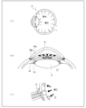
- FIG. 5 is an explanatory diagram of an outline of glaucoma.
- the eyeball 1 is always kept round. This is because the eyeball 1 is filled with a gel-like substance called vitreous and water-soluble aqueous humor.
- the eyeball 1 is kept in shape because there is an intraocular pressure determined by the balance of aqueous humor produced from the ciliary epithelium 10 and its outflow from the corner and the episcleral vein pressure. is there.
- the aqueous humor is secreted from the site of the ciliary epithelium 10, passes between the lens capsule 8 and the iris 6, reaches the anterior chamber, and passes through the trabecular belt 18a to the Schlemm's canal. It circulates through a fixed route that is discharged from 18b and flows to a blood vessel outside the eye.
- the place of the outflow path of the aqueous humor including the trabecular meshwork 18 a is referred to as a corner 18.
- glaucoma is a disease in which the intraocular pressure is increased and the optic nerve 15 is damaged, resulting in characteristic optic disc disorders and abnormal visual functions such as visual field abnormalities. In other words, measuring intraocular pressure as accurately as possible may prevent the progression of glaucoma.
- Patent Document 1 discloses a method in which the tip of a probe pen is brought into contact with the eyeball 1 and the intraocular pressure is measured through a vibration propagation liquid.
- Patent Document 2 air is sprayed onto the cornea 2 of the eye to be examined, the deformation of the cornea 2 is optically detected, and the intraocular pressure of the eye to be examined is determined based on the air pressure when the applanation of the cornea 2 is detected.
- a method of measuring is disclosed.
- Patent Document 3 discloses a method for measuring intraocular pressure based on a state of a pulse wave incident on the eyeball 1 of the eye to be examined and a state of a reflected wave in which the incident pulse wave is reflected from the eyeball 1. It is disclosed.
- Patent Document 4 discloses an antenna in which an intraocular lens is disposed inside an annular support member having a coil provided on the outer periphery as an antenna.
- an electronic module is provided on a part of the annular support member at a position where it comes into contact with the intraocular lens.
- This electronic module is provided with a sensor, and in the crystalline lens capsule that receives the intraocular lens, on the outer side of the eye (the direction in which the cornea 2 is seen from the crystalline lens capsule 8) with the ciliary zonule (chin zonule) 9 in between.
- the part is the anterior capsule 8a, and the part inside the eye (the direction in which the optic nerve 15 is seen when viewed from the lens capsule 8) is sandwiched between the chin zonules 9 (substantially elliptical rear half). 8b, this sensor is configured to measure the pressure on the anterior capsule 8a.
- this sensor is configured to measure the pressure on the anterior capsule 8a.
- FIGS. 1 and 2 plan view of Patent Document 4
- the sensor faces the anterior capsule 8a side
- FIG. 4 cross-sectional view of Patent Document 4
- the sensor is on the anterior capsule 8a side. It is exposed in the direction.
- Patent Document 5 discloses an intraocular lens having a antenna and a sensor used as an antenna (for example, FIGS. 99A to 99C of Patent Document 5). As an application of this sensor, the measurement of intraocular pressure is disclosed in paragraph [0127] of the same document, for example. In addition, it is described in paragraph [0865] of the document that a sensor is attached to one of antennas used as an antenna.
- the intraocular pressure of the subject is determined only after the subject wears the measuring device. In other words, whether or not the intraocular pressure of the subject is normal or abnormal can only be determined by measuring the intraocular pressure with an intraocular pressure measuring device. That is, when intraocular pressure is measured, there is a possibility that glaucoma has already developed and visual field loss has already occurred. Therefore, from the viewpoint of preventing the progression of glaucoma, it is highly desirable to measure the intraocular pressure of the subject in real time.
- Patent Documents 4 to 5 certainly describe that a sensor is provided in an intraocular lens.
- the onset mechanism of glaucoma causes an increase in intraocular pressure due to an increase in the amount of aqueous humor that constitutes the vitreous body 11 in the eye, and causes compression of the optic nerve 15 to cause visual field loss. It is said that.
- the pressure of the vitreous body 11 when the optic nerve 15 is compressed by the vitreous body 11 is also referred to as “pressure in the vitreous body 11”.
- the main object of the present invention is to provide an intraocular lens that suppresses the progression risk of glaucoma by measuring in real time a pressure that is the same as or very close to the intravitreal pressure.
- the present inventor examined “how to measure the pressure in the vitreous body 11 by the intraocular lens disposed inside the lens capsule 8”. In addition, “how to measure the value in accordance with the pressure in the vitreous body 11 in real time” was also examined.
- the amount of displacement of the cornea 2 of the eye to be examined is used as a basis for measuring intraocular pressure. It was. Assuming that a sensor for measuring the amount of displacement of the cornea 2 of the eye to be examined is provided by an intraocular lens as in the above-mentioned patent document, an optical unit (in particular, a person wearing the intraocular lens of the intraocular lens). It would be preferable for those skilled in the art to provide a sensor and a member covering the periphery thereof in a portion that does not enter the field of view.
- the actual amount of displacement can be measured more accurately if the sensor unit is provided near the portion where the amount of displacement is the largest.
- wearer the person wearing the intraocular lens
- sensor unit a member covering the sensor and its surroundings is also simply referred to as a “sensor unit”.
- the present inventor reexamined the cause of glaucoma away from the intraocular pressure measurement method as described in Patent Documents 1 and 2.
- glaucoma focused on the fact that the pressure in the vitreous body 11 that compresses the optic nerve 15 is the main factor of glaucoma rather than the pressure in the entire eye.
- the inventor has conducted extensive research and found that the pressure in the vitreous body 11 can be transmitted to the intraocular lens very faithfully through the posterior capsule 8b of the lens capsule 8. Obtained.
- the present inventor has realized that various inconveniences may occur when the sensor unit is provided in the optical unit as in the past in order to realize this knowledge. That is, in the past, in order to measure the displacement amount of the cornea 2, a sensor unit was provided in the vicinity of the portion with the largest displacement amount (that is, the optical unit). It is necessary to always or almost always contact with the sac 8b. Otherwise, the pressure in the vitreous body 11 cannot be accurately transmitted to the sensor unit in real time.
- the intraocular lens does not always move so much in the lens capsule 8 so as not to release the contact state of the lens capsule 8 with the posterior capsule 8b.
- the optical part in the intraocular lens is arranged in the capsular bag 8, it is located at a substantially central portion in the capsular bag 8.
- an impact is applied to the intraocular lens, and the lens capsule 8 The intraocular lens is displaced in the optical axis direction of the optical unit. Then, the contact state between the posterior capsule 8b and the intraocular lens in the lens capsule 8 is released.
- the optical part of the intraocular lens is suspended and supported by the support part in the crystalline lens capsule 8, the amount of displacement is particularly large, and the contact state with the posterior capsule 8b is easily released. As a result, it becomes difficult to measure the pressure in the vitreous body 11 in real time.
- the present inventor does not provide a sensor unit in the optical unit, but arranges it in the lens capsule 8 as shown in FIG.
- a configuration has been conceived in which the sensor unit 40 is provided on the support unit 22 having a relatively small displacement. And the structure which transmits the numerical value of the pressure in the vitreous body 11 from the sensor part 40 in the support part 22 to the antenna part 30 in the optical part 21, and also transmitted the numerical value of the pressure to the exterior was devised.
- the sensor unit 40 is not provided in the optical unit 21 which is a large displacement amount, but on the contrary, the support which is a relatively small displacement portion is supported.
- the sensor part 40 was provided in the part 22, and the knowledge that the pressure in the vitreous body 11 transmitted from the back capsule 8b was measured was acquired.
- the first aspect of the present invention is: An intraocular lens comprising: an optical part having a predetermined refractive power; and a support part that supports the optical part in the lens capsule.
- the support part is provided with a sensor part for measuring the pressure in the vitreous through the posterior capsule in the crystalline lens capsule,
- the optical unit is provided with an antenna unit that transmits the pressure measured by the sensor unit to the outside.
- the sensor unit is provided in a portion of the support unit near a boundary between the optical unit and the support unit.
- the sensor section is provided on the support section so that the sensor section is positioned in the vicinity of the posterior capsule.
- the optical part is formed of a soft material
- In the support part at least a part of the vicinity of the boundary between the optical part and the support part is formed of a hard material as compared with the soft material,
- the sensor unit is provided in at least a part of the above.
- the risk of progression of glaucoma can be suppressed by measuring in real time a pressure that is the same as or very close to the intravitreal pressure.
- FIG. 1A and 1B are explanatory views showing a configuration example of an intraocular lens according to an embodiment of the present invention, in which FIG. 3A is a plan view, FIG. (D) is a cross-sectional view taken along the line BB 'when the boundary portion between the optical part and the support part in the intraocular lens is enlarged.
- the A-A ′ line is also a folding line of the intraocular lens.
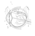
- FIG. 1 is a diagram illustrating a planar cross-sectional structure of an eyeball.
- the eyeball 1 has a spherical shape as a whole, and is covered and protected by the sclera 3 except for the front cornea 2.
- the surface of the sclera 3 around the cornea 2 is covered with a conjunctiva 4.
- the cornea 2 functions not only as an eyeball protection function but also as a lens that refracts incoming light.
- On the inner side (back side) of the cornea 2 is an anterior chamber 5 filled with aqueous humor, and a pupil 7 is located in the center of the iris 6 facing the anterior chamber 5.
- the iris 6 functions to adjust the amount of light incident on the inside of the eyeball 1 by adjusting the size of the pupil 7 (the size of the opening).
- the front surface of the lens capsule 8 faces the pupil 7.
- a ciliary epithelium 10 is connected to the lens capsule 8 via a ciliary zonule (chin zonule) 9.
- the ciliary epithelium 10 is a muscular tissue that focuses by controlling the thickness of the lens capsule 8.
- the vitreous body 11 occupies most of the inside of the eyeball 1.
- the vitreous body 11 is a jelly-like colorless and transparent tissue, and maintains the shape and elasticity of the eyeball 1. Further, the vitreous body 11 functions to send the light refracted by the lens capsule 8 to the retina 13.
- the retina 13 is a membrane tissue located on the innermost side in the eyeball 1. In the retina 13, there are photoreceptor cells that sense light incident into the eyeball 1 through the pupil 7 and identify its intensity, color, shape, and the like.
- the choroid 14 is a membrane tissue located inside the sclera 3 (that is, between the sclera 3 and the retina 13).
- the choroid 14 is rich in blood vessels, and also serves as a blood flow path to each tissue of the eyeball 1 to give nutrition to the eyeball 1.
- an optic nerve 15 is connected to the back side (back side) of the eyeball 1.
- the optic nerve 15 is a nerve that transmits light stimulation received by the retina 13 to the brain.
- a blind spot 16 is present at a portion where the optic nerve 15 is connected.
- the blind spot 16 is located 4 to 5 mm away from the fovea 17.
- the lens is colorless and transparent and has a convex lens shape via the lens capsule 8, and a muscle called the ciliary epithelium 10 is connected and supported by the chin zonule 9.
- the lens becomes thicker when the ciliary epithelium 10 contracts and the chin strip 9 relaxes when looking closer.
- the ciliary epithelium 10 relaxes and the chin band 9 is pulled, so that it becomes thin. In this way, the crystalline lens is focused on the perspective.
- Lens capsule The surface of the lens is wrapped with a thin film called the lens capsule 8.
- the lens capsule 8 is a film-like structure rich in elasticity, and maintains its properties under constant pressure.
- the outer portion of the eye across the ciliary zonule (chin zonule) 9 is referred to as the “anterior capsule”, and the eye is viewed from the chin zonule 9.
- the inner part is called the “posterior capsule”.
- Intraocular lens Next, the intraocular lens will be described.
- the intraocular lens in the present embodiment is assumed to be attached when the lens is extracted by an eye cataract surgery.
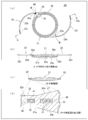
- FIG. 2 is an explanatory diagram showing a configuration example of the intraocular lens 20.
- the intraocular lens 20 includes an optical part 21 having a substantially circular shape in plan view, two arm-like and wire-like support parts 22 extending from the outer peripheral part of the optical part 21, and It is composed of
- the optical unit 21 and the support unit 22 can be formed of different materials, but in the present embodiment, both are formed integrally.
- a step portion 21 a is provided at the boundary portion between the optical unit 21 and the support unit 22.
- This stepped portion 21 a makes it easy for the optical portion 21 to be in close contact with the posterior capsule 8 b of the crystalline lens capsule 8 reliably. Therefore, it becomes possible to suppress the migration of the lens epithelial cells to the rear surface 20b side of the intraocular lens 20, and it is possible to suppress the risk of subsequent cataract progression caused by the lens epithelial cells.
- step-difference part 21a is a level
- the optical unit 21 is located at the approximate center of the entire intraocular lens 20, and the shape thereof is a circular or elliptical part in plan view.
- the optical unit 21 has a predetermined refractive power. This refractive power secures the refractive power of the lens removed to cope with cataract. That is, when the intraocular lens 20 is inserted into the crystalline lens capsule 8 and light from outside the eye passes through the optical unit 21, the wearer of the intraocular lens 20 can obtain the refractive power before removing the crystalline lens. .
- FIG. 2 shows a case where both the front surface 20a and the rear surface 20b of the intraocular lens 20 (particularly the optical unit 21) have a convex shape.
- the antenna unit 30 is formed on the outer periphery of the optical unit 21.
- the sensor unit 40 (described later) in the support unit 22 is operable by the power received by the antenna unit 30.
- the antenna unit 30 is configured by covering a plurality of proximity coil windings 31 with members constituting the optical unit 21.
- the coil winding 31 is arranged in an annular shape so as to circulate around the optical axis of the optical unit 21, and a plurality of coil windings 31 are arranged close to each other.
- the plurality of coil windings 31 are embedded in the optical unit 21.
- the coil winding 31 exists in a ring shape in a plane orthogonal to the optical axis.
- the coil winding 31 in the antenna unit 30 is arranged on the outer periphery of the optical unit 21, so that a certain length in the coil winding 31 can be ensured even if the intraocular lens 20 is downsized.
- power can be supplied from the outside using electromagnetic induction to the electronic module 32 (described later) in the antenna unit 30 and the sensor unit 40 in the support unit 22.
- the numerical value of the pressure in the vitreous body 11 obtained by the sensor unit 40 in the support unit 22 to be described later can be stably transmitted to a reception device (not shown) outside the eye.
- the “outer peripheral part” here is a part of the optical part 21, and an outer peripheral part away from the geometric center of the optical part 21 to the extent that the wearer of the intraocular lens 20 does not visually recognize the antenna part 30.
- a known material may be used as long as it can receive power from the outside using electromagnetic induction and transmit the numerical value of the pressure as the antenna unit 30. good.
- precious metals particularly gold, in view of conductivity and flexibility in folding.
- a groove for the coil winding 31 is formed in the optical unit 21 in advance, and after the coil winding 31 is fitted into the groove, the same material as the optical unit 21 is formed.
- the coil winding 31 is embedded with this member to form the antenna unit 30.
- the antenna unit 30 includes at least one electronic module 32 in addition to the coil winding 31.
- the electronic module 32 has a function of receiving the numerical value of the pressure in the vitreous body 11 transmitted from the sensor unit 40 and further allowing the numerical value to be transmitted to an external receiving device by a wireless method. The electric power at that time is supplied from the outside by the coil winding 31.
- the electronic module 32 is in contact with the coil winding 31 having an antenna function.
- the coil winding 31 be substantially straight rather than arcuate in plan view in the vicinity of the electronic module 32.
- a memory may be provided inside the electronic module 32. This memory stores the pressure value in the vitreous body 11 continuously measured and recorded in real time by the sensor unit 40 described later. These pressure values can be retrieved from this memory at appropriately determined intervals and transmitted to a receiving device outside the eye. A known device can be used as this receiving device.
- the electronic module 32 is made of a foldable material. As a result, the size of the intraocular lens 20 can be reduced, and as a result, the wound for inserting the intraocular lens 20 into the lens capsule 8 can be minimized. However, in order to minimize the damage to the electronic module 32, the optical unit should not be present at the folding position (on the line AA ′ in FIG. 2A) when the intraocular lens 20 is folded. It is preferable to arrange the electronic module 32 at 21. For example, as shown in FIG. 2A, it is preferable to arrange the electronic module 32 in a portion of the optical unit 21 in the vicinity of the boundary between the optical unit 21 and the support unit 22.
- the support portion 22 is a part of the intraocular lens 20 and is a portion extending outward from the optical portion 21 into an open loop shape and two arms.
- the support portion 22 draws a smoothly continuous arc from a portion near the boundary between the optical portion 21 and the support portion 22 to the distal end portion 22c.
- the optical unit 21 and the support unit 22 are integrally molded.
- a sensor unit 40 is provided in a portion of the support unit 22 near the boundary between the optical unit 21 and the support unit 22 (hereinafter also referred to as “base 22a”).
- the sensor unit 40 is not merely for measuring the intraocular pressure as in the prior art, but has a function of measuring the pressure in the vitreous body 11 via the posterior capsule 8b in the lens capsule 8.
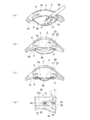
- the intraocular lens 20 in this embodiment is a lens capsule.
- the lens capsule 8 When the lens capsule 8 is inserted into the lens capsule 8 (FIGS. 3 (a) and 3 (b)), the lens capsule 8 is kept in a substantially elliptical shape to some extent, but the lens capsule 8 becomes constant by adapting to the intraocular lens 20. The degree is reduced, and the intraocular lens 20 and the lens capsule 8 come into contact with each other (FIG. 3C).
- the sensor unit 40 is provided on the support unit 22 as described above by utilizing the contact between the intraocular lens 20 and the lens capsule 8 (particularly the posterior capsule 8b). By doing so, since the intraocular lens 20 and the lens capsule 8 are in contact with each other, pressure is applied to the sensor unit 40 from the rear capsule 8 b of the lens capsule 8. At this time, the main factor of the pressure applied to the posterior capsule 8b is the pressure in the vitreous body 11 from the positional relationship between the lens capsule 8 and the vitreous body 11. As a result, when the intraocular lens 20 has the above-described configuration, the pressure in the vitreous body 11 is faithfully transmitted to the sensor unit 40 via the posterior capsule 8b of the crystalline lens capsule 8 ( FIG. 3 (d)). A pressure that is the same as or very close to the pressure in the vitreous body 11 can be measured in real time.
- the root 22a of the support portion 22 is the end portion of the support portion 22 (when viewed from the center of the optical portion 21 when the intraocular lens 20 is viewed in plan view). And a portion that is relatively close to the center of the optical unit 21.
- the capsular bag 8 is substantially elliptical in cross-sectional view and the mutual arrangement of the capsular bag 8 and the vitreous body 11, the pressure in the vitreous body 11 is closer to the center of the optical part 21 in the posterior capsule 8b. Is easier to communicate.
- the lens capsule 8 is provided although the sensor unit 40 is not provided in the optical unit 21.
- the pressure in the vitreous body 11 is more faithfully transmitted to the sensor unit 40 in the support unit 22 through the rear capsule 8b.
- the sensor unit 40 is provided in the support unit 22 at a position near the center of the optical unit 21.
- the sensor unit 40 is provided on the support portion 22 on the back capsule 8b side. That is, the sensor unit 40 is provided on the posterior capsule 8b side in the thickness direction.
- the sensor unit 40 includes the sensor 41 for measuring the pressure in the vitreous body 11 and the member 42 covering the periphery thereof.
- the sensor 41 is a sensor 41 that is the main body of the sensor unit 40 and is an electronic module (in order to distinguish it from the electronic module 32 in the antenna unit 30, the 41 ").
- the sensor 41 includes a pressure-sensitive element for sensing pressure applied from the posterior capsule 8b (that is, pressure in the vitreous body 11), and an electric circuit for transmitting the measured pressure to the antenna unit 30. I have.
- the surrounding member 42 is a material constituting the support portion 22. That is, in the present embodiment, the sensor 41 is embedded in the base 22 a of the support portion 22.
- this sensor 41 if it is a pressure sensor which can measure the pressure applied from the back capsule 8b in real time, you may use a well-known pressure sensor. Further, similarly to the electronic module 32 in the antenna unit 30, a memory may be provided inside the sensor 41.
- a hole for the sensor 41 is formed in the support portion 22 in advance like the coil winding 31 in the antenna portion 30, and the sensor 41 is fitted into the hole. Then, the sensor 41 is embedded with a member made of the same material as the support portion 22 to form the support portion 22.
- soft acrylic is used for the optical unit 21 and soft acrylic and PMMA are used for the support unit 22.
- PMMA which is a hard material, is used in the vicinity of the boundary between the optical unit 21 and the support unit 22 in the support unit 22.
- the sensor 41 is embedded in the part which consists of this PMMA.
- the “displacement amount is relatively small” that is a feature of the present embodiment can be more reliably performed.
- the effect of can be further exhibited. That is, by configuring the periphery of the sensor 41 with PMMA, which is a hard material, the amount of displacement when an impact is applied to the intraocular lens 20 can be made smaller than in the case of a soft material. As a result, in the support portion 22 with a small displacement amount, the displacement amount can be further reduced, and the contact between the posterior capsule 8b and the sensor portion 40 can be maintained almost always. Thus, the pressure in the vitreous body 11 that applies pressure to the optic nerve 15 can be constantly observed in real time.
- PMMA which is a hard material
- PMMA is used also for the front-end
- FIG. 1 In this way, after the intraocular lens 20 is folded, when the intraocular lens 20 is returned to the original shape again in the crystalline lens capsule 8, due to the difference in hardness and the adhesive force between the tip 22c and the optical part 21 The folding is easily released.
- the portion of the support portion 22 other than the tip portion 22c and the root 22a (hereinafter also referred to as “support portion main body 22b”) is made of soft acrylic.
- the support portion 22 is also folded when the intraocular lens 20 is folded, but breakage of the support portion 22 at the time of folding can be suppressed. Further, ⁇ 6. As described in Modification>, it is possible to prevent the support portion 22 from being damaged when the intraocular lens 20 is a sewing type.
- the tip end portion 22c and the support portion main body 22b are separated from each other, the tip end portion 22c and the support portion main body 22b are separated from each other when the arc line having the center of the optical unit 21 is concentric. It is divided as a line. Furthermore, when the support part main body 22b and the base 22a draw the circular arc line which makes the center of the optical part 21 concentric, the said circular arc line is divided as a boundary line.
- the base 22a of the support portion 22 is formed in a mountain-like shape toward the geometric center of the optical portion 21 when viewed in plan, and is connected to the optical portion 21 at the widest portion.
- the support portion main body 22b extends from the base 22a to the outside so as to draw a circular arc obliquely outward.
- tip part 22c part is formed a little wider than the support part main body 22b.
- the tip 22c is rounded so as not to damage the lens capsule 8 even if it contacts the lens capsule 8. Further, the tip 22c, the base 22a, and the support body 22b constituting the support part 22 are structurally integrated only in the materials of the respective parts.
- the main surface of the support portion 22 is continuous between the optical portion 21 and the support portion 22 when viewed in cross section. It may have a surface shape.
- a stepped portion 21a may be provided at the boundary portion between the optical unit 21 and the support unit 22 as described above.
- the cross-sectional shape of the support portion 22 initially extends substantially horizontally from the center of the optical portion 21 outward, and thereafter has an inclination toward the front surface 20a. Then, it may extend substantially horizontally.
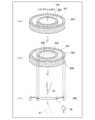
- an annular outer hard material portion 201 is obtained by a known molding method using, for example, PMMA (hard material). Then, an inner hard material portion 202 is formed inside the outer circular hole 101 ′ with the outer circular hole 101 ′ interposed therebetween. Then, an inner circular hole 102 ′ is formed inside the inner hard material portion 202 with the inner hard material portion 202 interposed therebetween.
- the outer hard material portion 201, the outer circular hole 101 ′, the inner hard material portion 202, and the inner circular hole 102 ′ are arranged concentrically.
- a soft acrylic raw material solution is injected into the outer circular hole 101 ′ and the inner circular hole 102 ′ after polymerization to complete the polymerization.
- the outer side soft material part 101 of planar view donut shape and the inner side soft material part 102 of circular shape by planar view are formed in the place where outer side circular hole 101 'and inner side circular hole 102' existed.
- the intermediate member 300 having a structure in which the outer hard material portion 201 and the inner hard material portion 202 and the outer soft material portion 101 and the inner soft material portion 102 are integrated is obtained.
- the surface shape of the intermediate member 300 is adjusted according to the surface shapes of the optical part 21 and the support part 22 to be completed.
- a common cutting tool 61 for surface machining and grooving for example, the curvature R of the tip is 0.2, the inclination from the tip is 30 °, and the radius of the portion without the tip is 0. 1
- a surface forming process such as milling is performed on the front and rear surfaces of the intermediate member 300.
- the surface shape of the intermediate member 300 is adjusted according to the convex curved surface of the optical unit 21, the slope of the root portion of the support unit 22, and the other flat surface.
- the disc-shaped intermediate member 300 reflecting the shape of the front surface 20a and the rear surface 20b of the intraocular lens 20 is obtained.
- the precision lathe device equipped with the grooving tool 62 is used to adjust the shape of the intermediate member 300 in accordance with the outline of the optical part 21 and the support part 22 when viewed in plan.
- the intermediate member 300 is grooved, and the intraocular lens 20 is cut out from the intermediate member 300 along the contour of the intraocular lens 20 to be completed.
- the circle is centered on the optical axis of the optical unit 21 and passes through a circle passing through the boundary between the region serving as the optical unit 21 and the region serving as the two support units 22 in the intermediate member 300.
- the first intermediate member is grooved by a precision lathe equipped with a grooving tool 62. Then, an unnecessary portion as the intraocular lens 20 is removed from the intermediate member 300 by performing an outer shape process such as a milling process on the intermediate member 300.
- This grooving process can be performed in a series of steps following the above-mentioned surface forming process, if a common cutting tool 61 for surface processing and grooving is used as the cutting tool in the surface forming process.
- the diameter of the grooving tool 62 is 1.5 mm.
- the grooving process may be performed by the milling device when the contour shape is formed by a milling device to be described later without performing the lathe processing. Thereafter, polishing is performed on necessary portions.
- the one-piece type intraocular lens 20 is obtained.
- all of the first to fourth steps described above may be performed simultaneously by a cast mold manufacturing method.
- the first step to the second step may be simultaneously performed by a cast mold manufacturing method, and then the third step to the fourth step may be performed.
- other known methods for example, a spin cast manufacturing method or a lace cut manufacturing method may be used.
- intraocular lens 20 There are two forms of use of the intraocular lens 20. One is a case where the intraocular lens 20 is used as a non-sewn type. The other is a case where the intraocular lens 20 is used as a sewing type. In the present embodiment, a method of using the intraocular lens 20 when the intraocular lens 20 is used as a non-sewn type will be described with reference to FIG. The sewing mold is described in ⁇ 6. Modification> will be described.
- a wound is formed on the surface of the eyeball 1 prior to that, and the lens (the lens cortex, the lens nucleus) is removed through the wound (FIG. 3A).
- the cataract lens is removed from the capsular bag 8 by forming a small circular opening (CCC: Continuous Curvular Capsular Hexis or Continuous Circular Capsule Hexis) 19 in the anterior capsule 8a of the capsular bag 8 by ultrasonic emulsification PEA) may be used.
- CCC Continuous Curvular Capsular Hexis or Continuous Circular Capsule Hexis
- the intraocular lens 20 is folded small in advance. At this time, the intraocular lens 20 is folded in such a manner that the optical part 21 is folded in two along the line A-A ′ of FIG. 2A so that the two support parts 22 do not overlap each other. At this time, the support portion 22 is also folded at the base 22 a, and the folded support portion 22 is wrapped with the optical portion 21.
- the intraocular lens 20 is inserted into the injector 50 while being folded.
- the injector 50 is a surgical instrument used for inserting the intraocular lens 20 into the eye.
- the intraocular lens 20 is inserted through the circular opening 19 by causing the distal end portion 51 of the injector 50 to which the intraocular lens 20 is attached to face the circular opening 19 of the eyeball 1 and pushing the intraocular lens 20 from the injector in this state. Is inserted into the eye (the lens capsule 8). At this stage, the intraocular lens 20 is in a folded state.
- the folded intraocular lens 20 is developed into the original shape using an insulator or the like (FIG. 3B).
- the capsular bag 8 becomes familiar with the intraocular lens 20, whereby the capsular bag 8 is reduced to a certain degree, and the intraocular lens 20 and the capsular bag 8 come into contact with each other (FIG. 3C).
- the support part 22 extended from the optical part 21 contacts the back capsule 8b of the crystalline lens capsule 8, and the optical part 21 is supported at an appropriate position using this contact pressure.
- the pressure in the vitreous body 11 is transmitted to the support portion 22.
- this pressure is transmitted by the sensor unit 40 at the base 22 a of the support unit 22.
- the sensor 41 of the sensor unit 40 measures the pressure in the vitreous body 11 via the posterior capsule 8b (and the member 42 covering the periphery of the sensor 41), and transmits the value to the electronic module 32 of the antenna unit 30. (FIG. 3 (d)).
- the pressure value is transmitted from the electronic module 32 to the outside in real time.
- the circular opening 19 may be closed by a known method after the operation.
- the intraocular pressure is not converted from the “displacement amount of the cornea 2” as in the prior art, but the “pressure in the posterior capsule 8b” that faithfully reflects the pressure in the vitreous body 11. Is measuring.
- absolute values for determining the possibility of progression of glaucoma with respect to what is obtained as an absolute value parameter for any patient pressure in the vitreous body 11 in this embodiment. It has succeeded in setting a value standard.
- the pressure in the vitreous body 11 can be measured in real time.
- the pressure in the vitreous body 11 that directly compresses the optic nerve 15 can be measured via the posterior capsule 8b without converting the amount of displacement of the cornea 2 to the pressure. Therefore, a value that faithfully reproduces the pressure in the vitreous body 11 can be measured by the sensor unit 40.
- the intraocular lens 20 is always present in the wearer's eye, it is possible to grasp in real time whether the pressure in the vitreous body 11 of the wearer is normal or abnormal, and this pressure tends to increase. Can quickly identify signs of glaucoma.
- the sensor unit 40 in order to accurately transmit the pressure in the vitreous body 11 to the sensor unit 40 in real time, the sensor unit 40 is connected to the support unit 22 so that the sensor unit 40 is always or almost always in contact with the posterior capsule 8b. 40 is arranged.
- an antenna unit 30 is provided in the optical unit 21. That is, the role is divided such that the pressure is measured by the support portion 22 and the pressure is transmitted to the outside by the optical portion 21.
- the coil winding 31 in the antenna unit 30 is arranged on the outer periphery of the optical unit 21, so that a certain length in the coil winding 31 is ensured even if the intraocular lens 20 is downsized. can do. As a result, the numerical value of the pressure in the vitreous body 11 can be transmitted and received stably.
- the intraocular lens 20 can suppress the risk of progression of glaucoma by measuring in real time a pressure that is the same as or very close to the pressure in the vitreous body 11.
- the integrated intraocular lens 20 in which the optical unit 21 and the support unit 22 are integrated from the stage of the intermediate member has been described.
- the application range of the present invention extends to a multi-piece type intraocular lens 20 which is not an integral type. That is, even in the multi-piece type intraocular lens 20, the sensor unit 40 is provided in the support unit 22, the antenna unit 30 is provided in the optical unit 21, and the pressure in the vitreous body 11 is applied to the posterior capsule 8 b by the sensor unit 40. If the measurement is performed via the above, the effect of the present embodiment is obtained.
- the step portion 21a is provided at the boundary portion between the support portion 22 and the optical portion 21, but the step portion 21a is made small so that the posterior capsule 8b can easily come into contact with the sensor portion 40 of the support portion 22.
- a configuration in which the step portion 21a is not provided may be employed.
- the optical unit 21 is preferably made of a soft material that allows the optical unit 21 to be folded.
- the term “foldable” described here is used to mean that the intraocular lens 20 including the optical unit 21 can be folded in at least two. Therefore, the soft material constituting the optical unit 21 may be a material having a high flexibility enough to fold the optical unit 21.
- soft acrylic soft materials such as silicone resin, acrylic resin, hydrogel, and urethane resin can be used.
- the present invention may be applied to an intraocular lens that does not require folding.
- PP polypropylene
- polyimide polyimide
- PMMA polymethyl methacrylate
- the present invention may be applied to a foldable intraocular lens.
- the optical unit 21 in the present embodiment is formed in a convex lens shape having a circular shape in plan view.
- the diameter of the optical unit 21 may be set to any size as long as it is a size suitable for inserting the intraocular lens 20 into the lens capsule 8 in the eye.
- the diameter D of the optical unit 21 is preferably set in the range of 5 mm to 7 mm, more preferably 6 mm. What is necessary is just to set the thickness of the optical part 21 according to a desired refractive index.
- the support portion 22 is made of a material having a hardness different from that of the optical portion 21, but the material is not limited in order to embody the idea of the present invention.
- the support unit 22 (at least the base 22a) is made of a hard material in order to stably arrange the optical unit 21. If a specific example is given as a material of the support part 22 other than PMMA, hard materials, such as a polypropylene and a polyamide, can be used.
- the whole support part 22 may be comprised with the same material
- tip part 22c, the support part main body 22b, and the base 22a may be comprised with a different material, respectively, and those combinations are comprised with the same material. You may do it.
- the base 22a uses a mixture of a hard material and a soft material. May be.
- the content ratio of the hard material may be changed (for example, decreased) from the optical part 21 side to the tip side of the base 22a, or the content ratio of the hard material is changed in the thickness direction of the support part 22 ( For example, it may be reduced). By doing so, the flexibility of the base portion 22a on the optical unit 21 side is further increased, and breakage during folding can be further suppressed.
- the support portion 22 in the present embodiment is formed in an open loop shape and an arm shape extending outward, and two of them are formed.
- the support portion 22 applied to the present invention may have other shapes. Specific examples include a support unit 22 that is not an open loop but a closed loop, a flat support 22 that is not an arm, or one or three or more support units 22 instead of two. Also good.
- the size of the support portion 22 in the present embodiment, when the size of the standard lens capsule 8 is taken into consideration, the diameter of the entire intraocular lens 20 is reduced when the intraocular lens 20 is inserted into the lens capsule 8.
- the total length of the support portion 22 is preferably set so as to be about 10 mm.
- the intraocular lens 20 when the intraocular lens 20 is a non-sewn type has been described.
- the intraocular lens 20 when the intraocular lens 20 is a sewn type will be described.
- the sewn-type intraocular lens 20 holds the optical unit 21 in an appropriate position by fixing the support unit 22 to the eyeball 1 with a suture while the intraocular lens 20 is housed in the crystalline lens capsule 8. That is, the type of intraocular lens 20. Then, a hole may be provided in the distal end portion 22c so that the suture thread passes through the intraocular lens 20.
- a hole may be provided in the distal end portion 22c so that the suture thread passes through the intraocular lens 20.
- the hole is formed on the extending end side of the support portion 22 so as to penetrate in the thickness direction of the support portion 22. Further, the hole is formed as a circular through hole in plan view. This hole corresponds to a locking portion that allows the suture used for fixing the support portion 22 to the eyeball 1 to be wound and prevents the wound suture from being displaced.
- the hole may be provided in the tip portion 22c, or may be provided in other portions.
- the support body 22b is made of soft acrylic, so that the optical part 21 can be elastically deformed in the radial direction. As shown in FIGS. 2 (a) and 2 (b), the support portion main body 22b extends as a whole elongated. And the material itself which comprises this has a moderate softness
- tip part 22c provided with the hole is comprised with the hard material harder than the support part main body 22b. This is because, when the suture thread is tied to the hole, even if the suture thread is tied up to some extent, the possibility that the portion (tip portion 22c) is torn off can be suppressed.
- Intraocular lens holder When the intraocular lens 20 according to the present embodiment is mounted in the crystalline lens capsule 8, it is known that maintaining the circular shape of the crystalline lens equator contributes to stabilization of lens fixation. Therefore, when attaching the intraocular lens 20 into the crystalline lens capsule 8, an auxiliary tool (an intracapsular holder) for attaching a lens called an intracapsular ring may be used. However, even when the intraocular lens 20 is fitted into the intracapsular ring, it is necessary to configure the intraocular lens 20 and the intracapsular ring so that the sensor unit 40 and the posterior capsule 8b in the support unit 22 can maintain a contact state. There is.
- the intraocular lens 20 may be attached to a holder that replaces the capsular bag 8.
- the pressure in the vitreous body is measured by bringing the sensor unit 40 and the vitreous body 11 into direct contact rather than through the posterior capsule 8b.
- a specific configuration in this case will be described in [Appendix] described later.
- an embedding member may be prepared separately, or a material different from the material constituting the optical unit 21 or the support unit 22 may be prepared separately for embedding.
- a gap for the electronic module 32 and the sensor 41 is provided in the optical unit 21 and the support unit 22 in advance, and the electronic module 32 and the sensor 41 are connected to the optical unit 21 and the support unit 22. It is also conceivable that, after being housed in, the lid in which the electronic module 32 and the sensor 41 are housed is covered using a separately prepared lid. However, it is necessary to select a material that has a slight influence on the wearer's eyes, whether it is the lid or the above-described embedding member.
- the antenna unit 30 If it functions as the antenna unit 30, there is no limitation on the winding method of the coil winding 31, but for example, the coil windings 31 are adjacent to each other in the radial direction of the optical unit 21.
- the antenna portion 30 may be formed in a planar and annular shape by winding the wire around the wire.
- the antenna unit 30 may be formed by stacking the planar antenna units 30 to form a plurality of planes composed of the coil windings 31.
- the sensor part 40 gave the example provided in the part of the support part 22 near the boundary between the optical part 21 and the support part 22. Moreover, when the intraocular lens 20 was inserted into the capsular bag 8, an example was given in which the sensor unit 40 is provided on the support unit 22 so that the sensor unit 40 is positioned in the vicinity of the posterior capsule 8 b. On the other hand, if the sensor 41 can sense the pressure in the vitreous body 11 via the posterior capsule 8b, the sensor unit 40 may be arranged at a location of the support unit 22 other than the above. If the above sensing can be ensured, the sensor unit 40 may be provided at the tip 22c of the support unit 22. Further, if the pressure in the vitreous body 11 can be accurately sensed via the posterior capsule 8b, the sensor unit 40 may be provided on the anterior capsule 8a side in the thickness direction.
- An intraocular lens comprising an optical part having a predetermined refractive power and a support part that supports the optical part, The support part is provided with a sensor part for measuring the pressure in the vitreous body by contacting with the vitreous body, An intraocular lens, wherein the optical unit is provided with an antenna unit that transmits the pressure measured by the sensor unit to the outside.
Abstract
An intraocular lens has an optical unit with a predetermined refractive power and a support part that supports the optical part in the lenticular capsule, wherein the support part has a sensor that measures the pressure in the vitreous body via the posterior capsule in the lenticular capsule, and the optical unit has an antenna section that transmits the pressure that was measured by the sensor to the outside.
Description
本発明は、眼内レンズに関し、特に、水晶体嚢内へ装着する眼内レンズに関する。
The present invention relates to an intraocular lens, and more particularly, to an intraocular lens mounted in a lens capsule.
人間の眼に関する疾患として、白内障が知られている。この「白内障」は、眼球の内部でレンズ機能を果たす水晶体が白く濁ることで、視力の低下等を招く病気である。
白 Cataract is known as a disease related to the human eye. This “cataract” is a disease that causes a decrease in visual acuity and the like due to white turbidity of the lens that performs the lens function inside the eyeball.
この白内障を発症した患者の視力を回復するために白内障手術+眼内レンズ移植術が行われている。上記の手術は、白く濁った水晶体を取り除き、そこに人工の眼内レンズ(IOL:IntraOcular Lens)を挿入する手術である。
”Cataract surgery + intraocular lens implantation is performed to restore the visual acuity of patients who have developed this cataract. The above-described operation is an operation for removing a white cloudy lens and inserting an artificial intraocular lens (IOL: IntraOcular Lens) therein.
眼内レンズ移植術で眼内に移植される眼内レンズは、水晶体に代わりに所定の屈折力を有する光学部と、光学部を支える支持部とによって構成されている。この種の眼内レンズは、水晶体を摘出した後に残る水晶体嚢の内部に収容される事が最も望ましい。その結果、白く濁った水晶体の代わりに、眼内レンズにより正常な視力を確保することができる。
An intraocular lens implanted in the eye by intraocular lens transplantation is constituted by an optical part having a predetermined refractive power instead of a crystalline lens and a support part that supports the optical part. This type of intraocular lens is most preferably housed in the capsular bag that remains after the lens is removed. As a result, normal visual acuity can be ensured by an intraocular lens instead of a white cloudy crystalline lens.
ところが、視力を喪失させる人間の眼に関する疾患として緑内障が存在する。この緑内障は白内障と共に発症している場合も少なくない。また、白内障しか発症していないとしても、後々、緑内障を発症する可能性も否定できない。
However, glaucoma exists as a human eye disease that causes vision loss. This glaucoma often occurs with cataracts. Moreover, even if only cataract has developed, the possibility that glaucoma will develop later cannot be denied.
この「緑内障」は、視野異常(具体的に言うと視野欠損)を及ぼす進行性の病気である。この緑内障を発症して視野を欠損すると、一度欠損した視野は回復させることが困難なため、失明の原因になり得る。
This “glaucoma” is a progressive disease that causes visual field abnormalities (specifically visual field defects). If this glaucoma develops and the visual field is lost, it is difficult to recover the visual field once lost, which can cause blindness.
ここで、緑内障およびその発症要因(進行要因)として考えられる事項について簡単に説明する。
図5は、緑内障の概要についての説明図である。
図5(a)に示すように、眼球1は、常に丸く保たれている。これは、眼球1の中は硝子体というゲル状の物質と水溶性の房水によって満たされている。眼球1が形状を保てているのは、毛様体上皮10から産生される房水と隅角からのその流出のバランスと上強膜静脈圧とによって決定されている眼圧があるからである。 Here, the glaucoma and the matter considered as the onset factor (progression factor) will be briefly described.
FIG. 5 is an explanatory diagram of an outline of glaucoma.
As shown in FIG. 5A, theeyeball 1 is always kept round. This is because the eyeball 1 is filled with a gel-like substance called vitreous and water-soluble aqueous humor. The eyeball 1 is kept in shape because there is an intraocular pressure determined by the balance of aqueous humor produced from the ciliary epithelium 10 and its outflow from the corner and the episcleral vein pressure. is there.
図5は、緑内障の概要についての説明図である。
図5(a)に示すように、眼球1は、常に丸く保たれている。これは、眼球1の中は硝子体というゲル状の物質と水溶性の房水によって満たされている。眼球1が形状を保てているのは、毛様体上皮10から産生される房水と隅角からのその流出のバランスと上強膜静脈圧とによって決定されている眼圧があるからである。 Here, the glaucoma and the matter considered as the onset factor (progression factor) will be briefly described.
FIG. 5 is an explanatory diagram of an outline of glaucoma.
As shown in FIG. 5A, the
房水は、図5(b)に示すように、毛様体上皮10という部位から分泌され、水晶体嚢8と虹彩6との間を通って前房に至り、線維柱帯18aを経てシュレム管18bから排出され、眼外の血管へ流れていくという定まった経路で循環している。なお、線維柱帯18aを含む房水の流出路の場所のことを隅角18と言う。
As shown in FIG. 5 (b), the aqueous humor is secreted from the site of the ciliary epithelium 10, passes between the lens capsule 8 and the iris 6, reaches the anterior chamber, and passes through the trabecular belt 18a to the Schlemm's canal. It circulates through a fixed route that is discharged from 18b and flows to a blood vessel outside the eye. In addition, the place of the outflow path of the aqueous humor including the trabecular meshwork 18 a is referred to as a corner 18.
図5(c)に示すように、緑内障は、この眼圧が上昇して視神経15を障害し、特徴的な視神経乳頭障害と視野異常などの視機能異常を来たす疾患である。つまり、できるだけ正確に眼圧を測定することが、緑内障の進行を予防できる可能性がある。
As shown in FIG. 5 (c), glaucoma is a disease in which the intraocular pressure is increased and the optic nerve 15 is damaged, resulting in characteristic optic disc disorders and abnormal visual functions such as visual field abnormalities. In other words, measuring intraocular pressure as accurately as possible may prevent the progression of glaucoma.
この眼圧を測定する装置については、種々のものが公知になっている。以下、説明の便宜上、人間の眼球等のように共通する項目については、特許文献1~5においても本願図面(特に図1及び図5)に記載の符号と同じ符号を付す。
Various devices for measuring this intraocular pressure are known. Hereinafter, for convenience of explanation, common items such as human eyeballs are denoted by the same reference numerals in Patent Documents 1 to 5 as those described in the drawings of the present application (particularly FIGS. 1 and 5).
例えば特許文献1では、プローブペンの先端を眼球1に接触させ、振動伝播液体を介しつつ、眼圧を測定する方法が開示されている。
For example, Patent Document 1 discloses a method in which the tip of a probe pen is brought into contact with the eyeball 1 and the intraocular pressure is measured through a vibration propagation liquid.
また、特許文献2では、被検眼の角膜2に空気を噴射し、当該角膜2の変形を光学的に検出し、当該角膜2の圧平を検出した際の空気圧に基づき被検眼の眼圧を測定する方法が開示されている。
Further, in Patent Document 2, air is sprayed onto the cornea 2 of the eye to be examined, the deformation of the cornea 2 is optically detected, and the intraocular pressure of the eye to be examined is determined based on the air pressure when the applanation of the cornea 2 is detected. A method of measuring is disclosed.
また、特許文献3では、被検眼の眼球1に入射されるパルス波の状態と、入射されたパルス波が眼球1から反射されてくる反射波の状態とに基づいて眼圧を測定する方法が開示されている。
Patent Document 3 discloses a method for measuring intraocular pressure based on a state of a pulse wave incident on the eyeball 1 of the eye to be examined and a state of a reflected wave in which the incident pulse wave is reflected from the eyeball 1. It is disclosed.
また、特許文献4では、アンテナとしてコイルが外周に設けられた環状支持部材の内側に、眼内レンズを配置したものについて開示されている。なお、この環状支持部材の一部には、眼内レンズと接触するような位置に電子モジュールが設けられている。この電子モジュールにはセンサが設けられており、眼内レンズを受け入れる水晶体嚢において、毛様小帯(チン小帯)9を挟んで眼外側(水晶体嚢8から見て角膜2がある方向)の部分(略楕円状の前半分)を前嚢8aとし、チン小帯9を挟んで眼内側(水晶体嚢8から見て視神経15がある方向)の部分(略楕円状の後半分)を後嚢8bとすると、このセンサは前嚢8aの方の圧力を測定するように構成されている。それを示すべく、特許文献4の図1及び図2(平面図)においてはセンサが前嚢8a側向きになっており、特許文献4の図4(断面図)においてはセンサが前嚢8a側向きに露出している。
Also, Patent Document 4 discloses an antenna in which an intraocular lens is disposed inside an annular support member having a coil provided on the outer periphery as an antenna. Note that an electronic module is provided on a part of the annular support member at a position where it comes into contact with the intraocular lens. This electronic module is provided with a sensor, and in the crystalline lens capsule that receives the intraocular lens, on the outer side of the eye (the direction in which the cornea 2 is seen from the crystalline lens capsule 8) with the ciliary zonule (chin zonule) 9 in between. The part (substantially elliptical front half) is the anterior capsule 8a, and the part inside the eye (the direction in which the optic nerve 15 is seen when viewed from the lens capsule 8) is sandwiched between the chin zonules 9 (substantially elliptical rear half). 8b, this sensor is configured to measure the pressure on the anterior capsule 8a. In order to show this, in FIGS. 1 and 2 (plan view) of Patent Document 4, the sensor faces the anterior capsule 8a side, and in FIG. 4 (cross-sectional view) of Patent Document 4, the sensor is on the anterior capsule 8a side. It is exposed in the direction.
また、特許文献5では、アンテナとして用いられている触角及びセンサを有する眼内レンズが開示されている(例えば特許文献5の図99A~C)。このセンサの用途としては、眼圧測定であることが、例えば同文献の段落[0127]に開示されている。また、アンテナとして用いられている触角の1つにセンサをつけることが、同文献の段落[0865]に記載されている。
Further, Patent Document 5 discloses an intraocular lens having a antenna and a sensor used as an antenna (for example, FIGS. 99A to 99C of Patent Document 5). As an application of this sensor, the measurement of intraocular pressure is disclosed in paragraph [0127] of the same document, for example. In addition, it is described in paragraph [0865] of the document that a sensor is attached to one of antennas used as an antenna.
特許文献1~2に記載の眼圧測定装置では、被検眼の角膜2の変位量を測定し、この変位量から眼圧を算出するという動作を行っている。一方、被験者の角膜2の厚さや弾力性等には個人差がある。そのため、従来の眼圧測定装置を用いた場合、本当は緑内障の症状が出始めており眼圧が高まっているにも拘わらず、被験者の角膜2の特性上、角膜2の変位量が低く測定されてしまい、緑内障のおそれがないという判断が下される可能性も否定できない。
In the intraocular pressure measuring devices described in Patent Documents 1 and 2, an operation is performed in which the amount of displacement of the cornea 2 of the eye to be examined is measured and the intraocular pressure is calculated from the amount of displacement. On the other hand, there are individual differences in the thickness and elasticity of the cornea 2 of the subject. Therefore, when a conventional intraocular pressure measuring device is used, the amount of displacement of the cornea 2 is measured low due to the characteristics of the cornea 2 of the subject despite the fact that symptoms of glaucoma have started to appear and the intraocular pressure has increased. Therefore, it cannot be denied that there is a possibility of being judged not to have glaucoma.
そのため、どの被験者に対しても絶対値的なパラメータとして得られるもの(例えば眼圧)について、緑内障の進行の可能性を判断するための絶対値基準を設ける必要がある。
Therefore, it is necessary to provide an absolute value standard for determining the possibility of progression of glaucoma for what is obtained as an absolute value parameter (for example, intraocular pressure) for any subject.
更に、特許文献1~3に記載の眼圧測定装置では、被験者が測定装置を装着して初めて、被験者の眼圧が判明する。別の言い方をすると、被験者の眼圧が正常か異常かは、眼圧測定装置にて眼圧を測定して初めて判明する。つまり、眼圧を測定した時には、既に緑内障を発症し視野欠損を既に引き起こしている可能性もあり得る。そのため、緑内障の進行を予防するという観点で言えば、被験者の眼圧をリアルタイムに測定することが極めて望ましい。
Furthermore, in the intraocular pressure measuring devices described in Patent Documents 1 to 3, the intraocular pressure of the subject is determined only after the subject wears the measuring device. In other words, whether or not the intraocular pressure of the subject is normal or abnormal can only be determined by measuring the intraocular pressure with an intraocular pressure measuring device. That is, when intraocular pressure is measured, there is a possibility that glaucoma has already developed and visual field loss has already occurred. Therefore, from the viewpoint of preventing the progression of glaucoma, it is highly desirable to measure the intraocular pressure of the subject in real time.
なお、特許文献4~5には確かに、眼内レンズにセンサを設けることが記載されている。だが、緑内障の発症メカニズムは、上述の通り、眼内における硝子体11を構成する房水の量が多くなって眼圧の上昇を引き起こしてしまい、視神経15の圧迫をもたらすことにより視野欠損が引き起こされる、というものである。その結果、視野欠損を進行させないためには、水晶体嚢8の内部の圧力を測定するよりも、視神経15を直接圧迫する硝子体11の圧力を測定するのが極めて望ましい。なお、硝子体11によって視神経15が圧迫される際の硝子体11の圧力のことを「硝子体11内の圧力」とも言う。
In addition, Patent Documents 4 to 5 certainly describe that a sensor is provided in an intraocular lens. However, as described above, the onset mechanism of glaucoma causes an increase in intraocular pressure due to an increase in the amount of aqueous humor that constitutes the vitreous body 11 in the eye, and causes compression of the optic nerve 15 to cause visual field loss. It is said that. As a result, in order to prevent the visual field defect from proceeding, it is highly desirable to measure the pressure of the vitreous body 11 that directly presses the optic nerve 15 rather than the pressure inside the lens capsule 8. Note that the pressure of the vitreous body 11 when the optic nerve 15 is compressed by the vitreous body 11 is also referred to as “pressure in the vitreous body 11”.
しかしながら、水晶体嚢8の内部ではなく、硝子体11内の圧力をリアルタイムに測定する方法については未だ公知となっていない。更に言えば、緑内障の進行を予防すべく、水晶体嚢8内の圧力ではなく、硝子体11内の圧力を測定する動機づけとなる文献についても未だ公知となっていない。
However, a method for measuring the pressure inside the vitreous body 11 instead of the inside of the lens capsule 8 in real time is not yet known. Furthermore, in order to prevent the progression of glaucoma, the literature that motivates the measurement of the pressure in the vitreous body 11 instead of the pressure in the capsular bag 8 is not yet known.
そこで本発明は、硝子体内の圧力と同じないし極めて近似する圧力をリアルタイムに測定することにより、緑内障の進行リスクを抑制する眼内レンズを提供することを、主たる目的とする。
Therefore, the main object of the present invention is to provide an intraocular lens that suppresses the progression risk of glaucoma by measuring in real time a pressure that is the same as or very close to the intravitreal pressure.
本発明者は、上記の課題を解決すべく、「水晶体嚢8の内部に配置した眼内レンズによって、いかにして硝子体11内の圧力を測定するか」について検討した。その上で、「硝子体11内の圧力に即した数値をいかにしてリアルタイムで測定するか」についても検討した。
In order to solve the above-mentioned problem, the present inventor examined “how to measure the pressure in the vitreous body 11 by the intraocular lens disposed inside the lens capsule 8”. In addition, “how to measure the value in accordance with the pressure in the vitreous body 11 in real time” was also examined.
この検討に際して、上記の特許文献について再検討した。そして、特許文献の中でも1~2について再検討を行った。
At the time of this review, the above patent document was reviewed. In the patent literature, 1-2 were reexamined.
特許文献1のような接触型の眼圧測定装置にせよ、特許文献2のような非接触型の眼圧測定装置にせよ、被検眼の角膜2の変位量を眼圧測定の基として使用していた。仮に、眼内レンズによって上記特許文献のように被検眼の角膜2の変位量を測定するセンサを設けるとするのならば、眼内レンズにおいて光学部(その中でも、眼内レンズを装用する者の視野に入らない部分)にセンサ及びその周囲を覆う部材を設けるのが当業者にとっては好ましいはずである。なぜなら、角膜2の変位量を測定するためには、変位量が最も大きい部分の近傍にセンサ部を設けた方が、実際の変位量を正確に測定できるためである。
なお、以降、眼内レンズを装用する者のことを単に「装用者」とも言う。また、センサ及びその周囲を覆う部材のことを単に「センサ部」とも言う。 Whether the contact-type intraocular pressure measurement device as inPatent Document 1 or the non-contact-type intraocular pressure measurement device as in Patent Document 2, the amount of displacement of the cornea 2 of the eye to be examined is used as a basis for measuring intraocular pressure. It was. Assuming that a sensor for measuring the amount of displacement of the cornea 2 of the eye to be examined is provided by an intraocular lens as in the above-mentioned patent document, an optical unit (in particular, a person wearing the intraocular lens of the intraocular lens). It would be preferable for those skilled in the art to provide a sensor and a member covering the periphery thereof in a portion that does not enter the field of view. This is because in order to measure the amount of displacement of the cornea 2, the actual amount of displacement can be measured more accurately if the sensor unit is provided near the portion where the amount of displacement is the largest.
Hereinafter, the person wearing the intraocular lens is also simply referred to as “wearer”. Further, a member covering the sensor and its surroundings is also simply referred to as a “sensor unit”.
なお、以降、眼内レンズを装用する者のことを単に「装用者」とも言う。また、センサ及びその周囲を覆う部材のことを単に「センサ部」とも言う。 Whether the contact-type intraocular pressure measurement device as in
Hereinafter, the person wearing the intraocular lens is also simply referred to as “wearer”. Further, a member covering the sensor and its surroundings is also simply referred to as a “sensor unit”.
そのような状況下で、本発明者は特許文献1~2のような眼圧測定方法から離れて、緑内障の原因について再検討した。その際、緑内障というものは、眼内全体の圧力というよりも、視神経15を圧迫する硝子体11内の圧力が、緑内障の主な要因となることに着目した。この着目に基づき、本発明者が鋭意研究を進めた結果、水晶体嚢8の後嚢8bを介してならば、硝子体11内の圧力を極めて忠実に眼内レンズへと伝達され得るという知見を得た。
Under such circumstances, the present inventor reexamined the cause of glaucoma away from the intraocular pressure measurement method as described in Patent Documents 1 and 2. At that time, glaucoma focused on the fact that the pressure in the vitreous body 11 that compresses the optic nerve 15 is the main factor of glaucoma rather than the pressure in the entire eye. Based on this focus, the inventor has conducted extensive research and found that the pressure in the vitreous body 11 can be transmitted to the intraocular lens very faithfully through the posterior capsule 8b of the lens capsule 8. Obtained.
ところが、この知見を実現しようとして従来のように光学部にセンサ部を設けると、諸々の不都合が生じることおそれがあることに、本発明者は気付いた。即ち、従来だと角膜2の変位量を測定するために変位量が最も大きい部分の近傍(即ち光学部)にセンサ部を設けていたものの、上記の知見を実現するためにはセンサ部が後嚢8bと常時ないしほぼ常時接触する必要がある。そうしなければ、硝子体11内の圧力を、リアルタイムでセンサ部へと正確に伝達できないためである。
However, the present inventor has realized that various inconveniences may occur when the sensor unit is provided in the optical unit as in the past in order to realize this knowledge. That is, in the past, in order to measure the displacement amount of the cornea 2, a sensor unit was provided in the vicinity of the portion with the largest displacement amount (that is, the optical unit). It is necessary to always or almost always contact with the sac 8b. Otherwise, the pressure in the vitreous body 11 cannot be accurately transmitted to the sensor unit in real time.
これを実現するためには、眼内レンズは、水晶体嚢8における後嚢8bとの接触状態を解除しないよう、水晶体嚢8内にて常時あまり変位しない方が好ましい。
しかしながら、眼内レンズにおける光学部は、水晶体嚢8内に配置するとなると水晶体嚢8内の略中心部分に位置することになる。そして、特許文献1~2のような眼圧測定を行う際のみならず、眼内レンズの装用者が眼を擦る等の動作を行うことにより、眼内レンズに衝撃が加えられ、水晶体嚢8内において、眼内レンズが光学部の光軸方向に変位することになる。そうなると、水晶体嚢8における後嚢8bと眼内レンズとの接触状態が解除されてしまう。特に、眼内レンズにおける光学部は、水晶体嚢8内において支持部に支えられて吊るされる形となるため、特に変位量が多くなり、後嚢8bとの接触状態が解除されやすくなってしまう。その結果、リアルタイムな硝子体11内の圧力測定が困難となってしまう。 In order to realize this, it is preferable that the intraocular lens does not always move so much in thelens capsule 8 so as not to release the contact state of the lens capsule 8 with the posterior capsule 8b.
However, when the optical part in the intraocular lens is arranged in thecapsular bag 8, it is located at a substantially central portion in the capsular bag 8. Further, not only when performing intraocular pressure measurement as in Patent Documents 1 and 2, but also by performing an operation such as a wearer of the intraocular lens rubbing the eye, an impact is applied to the intraocular lens, and the lens capsule 8 The intraocular lens is displaced in the optical axis direction of the optical unit. Then, the contact state between the posterior capsule 8b and the intraocular lens in the lens capsule 8 is released. In particular, since the optical part of the intraocular lens is suspended and supported by the support part in the crystalline lens capsule 8, the amount of displacement is particularly large, and the contact state with the posterior capsule 8b is easily released. As a result, it becomes difficult to measure the pressure in the vitreous body 11 in real time.
しかしながら、眼内レンズにおける光学部は、水晶体嚢8内に配置するとなると水晶体嚢8内の略中心部分に位置することになる。そして、特許文献1~2のような眼圧測定を行う際のみならず、眼内レンズの装用者が眼を擦る等の動作を行うことにより、眼内レンズに衝撃が加えられ、水晶体嚢8内において、眼内レンズが光学部の光軸方向に変位することになる。そうなると、水晶体嚢8における後嚢8bと眼内レンズとの接触状態が解除されてしまう。特に、眼内レンズにおける光学部は、水晶体嚢8内において支持部に支えられて吊るされる形となるため、特に変位量が多くなり、後嚢8bとの接触状態が解除されやすくなってしまう。その結果、リアルタイムな硝子体11内の圧力測定が困難となってしまう。 In order to realize this, it is preferable that the intraocular lens does not always move so much in the
However, when the optical part in the intraocular lens is arranged in the
本発明者によって得られた上記課題を解決すべく、本発明者は、光学部にセンサ部を設けるのではなく、後述する図3(d)のように、水晶体嚢8内に配置した際に変位量が比較的小さい支持部22にセンサ部40を設けるという構成を想到した。そして、支持部22におけるセンサ部40から、光学部21におけるアンテナ部30へと硝子体11内の圧力の数値を伝達し、更には外部へその圧力の数値を伝達するという構成を想到した。
In order to solve the above-mentioned problem obtained by the present inventor, the present inventor does not provide a sensor unit in the optical unit, but arranges it in the lens capsule 8 as shown in FIG. A configuration has been conceived in which the sensor unit 40 is provided on the support unit 22 having a relatively small displacement. And the structure which transmits the numerical value of the pressure in the vitreous body 11 from the sensor part 40 in the support part 22 to the antenna part 30 in the optical part 21, and also transmitted the numerical value of the pressure to the exterior was devised.
つまり、角膜2を変位させて眼圧を測定すべく変位量が大きな部分である光学部21にセンサ部40を設けるのではなく、それとは全く逆に、変位量が比較的小さい部分である支持部22にセンサ部40を設け、後嚢8bから伝えられる硝子体11内の圧力を測定するという知見を得た。
That is, in order to measure the intraocular pressure by displacing the cornea 2, the sensor unit 40 is not provided in the optical unit 21 which is a large displacement amount, but on the contrary, the support which is a relatively small displacement portion is supported. The sensor part 40 was provided in the part 22, and the knowledge that the pressure in the vitreous body 11 transmitted from the back capsule 8b was measured was acquired.
以上の知見に基づいて成された本発明の態様は、以下の通りである。
本発明の第1の態様は、
所定の屈折力を有する光学部と、水晶体嚢内にて前記光学部を支える支持部と、を備える眼内レンズであって、
前記支持部には、前記水晶体嚢における後嚢を介して硝子体内の圧力を測定するセンサ部が設けられ、
前記光学部には、前記センサ部にて測定された前記圧力を外部に伝達するアンテナ部が設けられている
ことを特徴とする眼内レンズである。
本発明の第2の態様は、第1の態様に記載の発明において、
前記センサ部は、前記支持部における、前記光学部と前記支持部との境界近傍の部分に設けられている
ことを特徴とする。
本発明の第3の態様は、第1または第2の態様に記載の発明において、
眼内レンズを水晶体嚢内に挿入したとき、前記センサ部が前記後嚢の近傍に位置するように、前記センサ部が前記支持部に設けられている
ことを特徴とする。
本発明の第4の態様は、第1から第3の態様のいずれか1態様に記載の発明において、
前記光学部は軟質材料から形成され、
前記支持部における、前記光学部と前記支持部との境界近傍の少なくとも一部は、前記軟質材料に比べて硬質な材料から形成されており、
前記少なくとも一部に、前記センサ部が設けられている
ことを特徴とする。 Aspects of the present invention based on the above findings are as follows.
The first aspect of the present invention is:
An intraocular lens comprising: an optical part having a predetermined refractive power; and a support part that supports the optical part in the lens capsule.
The support part is provided with a sensor part for measuring the pressure in the vitreous through the posterior capsule in the crystalline lens capsule,
In the intraocular lens, the optical unit is provided with an antenna unit that transmits the pressure measured by the sensor unit to the outside.
According to a second aspect of the present invention, in the invention according to the first aspect,
The sensor unit is provided in a portion of the support unit near a boundary between the optical unit and the support unit.
According to a third aspect of the present invention, in the invention according to the first or second aspect,
When the intraocular lens is inserted into the crystalline lens capsule, the sensor section is provided on the support section so that the sensor section is positioned in the vicinity of the posterior capsule.
According to a fourth aspect of the present invention, in the invention according to any one of the first to third aspects,
The optical part is formed of a soft material,
In the support part, at least a part of the vicinity of the boundary between the optical part and the support part is formed of a hard material as compared with the soft material,
The sensor unit is provided in at least a part of the above.
本発明によれば、硝子体内の圧力と同じないし極めて近似する圧力をリアルタイムに測定することにより、緑内障の進行リスクを抑制できる。
According to the present invention, the risk of progression of glaucoma can be suppressed by measuring in real time a pressure that is the same as or very close to the intravitreal pressure.
以下、本発明の実施の形態について図面を参照しつつ詳細に説明する。
本実施形態においては、次の順序で説明を行う。
1.眼球の構造
A)眼球の全体構造
B)水晶体
C)水晶体嚢
2.眼内レンズ
A)眼内レンズの全体構造
B)光学部(含むアンテナ部)
C)支持部(含むセンサ部)
3.眼内レンズの製造方法
4.眼内レンズの使用方法
5.実施の形態による効果
6.変形例 Hereinafter, embodiments of the present invention will be described in detail with reference to the drawings.
In the present embodiment, description will be given in the following order.
1. Structure of eyeball A) Overall structure of eyeball B) Lens C) Lens capsule Intraocular lens A) Overall structure of intraocular lens B) Optical part (including antenna part)
C) Support part (including sensor part)
3. 3. Manufacturing method ofintraocular lens 4. Use of intraocular lens Effects of the embodiment 6. Modified example
本実施形態においては、次の順序で説明を行う。
1.眼球の構造
A)眼球の全体構造
B)水晶体
C)水晶体嚢
2.眼内レンズ
A)眼内レンズの全体構造
B)光学部(含むアンテナ部)
C)支持部(含むセンサ部)
3.眼内レンズの製造方法
4.眼内レンズの使用方法
5.実施の形態による効果
6.変形例 Hereinafter, embodiments of the present invention will be described in detail with reference to the drawings.
In the present embodiment, description will be given in the following order.
1. Structure of eyeball A) Overall structure of eyeball B) Lens C) Lens capsule Intraocular lens A) Overall structure of intraocular lens B) Optical part (including antenna part)
C) Support part (including sensor part)
3. 3. Manufacturing method of
<1.眼球の構造>
ここで、本発明に係る眼内レンズの説明に先立ち、当該眼内レンズが用いられる眼球の構造について説明する。 <1. Eyeball Structure>
Prior to the description of the intraocular lens according to the present invention, the structure of the eyeball in which the intraocular lens is used will be described.
ここで、本発明に係る眼内レンズの説明に先立ち、当該眼内レンズが用いられる眼球の構造について説明する。 <1. Eyeball Structure>
Prior to the description of the intraocular lens according to the present invention, the structure of the eyeball in which the intraocular lens is used will be described.
A)眼球の全体構造
図1は、眼球の平面的な断面構造を説明する図である。
図例のように、眼球1は、全体に球状をなし、前方の角膜2の部分を除いて強膜3により被覆保護されている。角膜2周囲の強膜3の表面は結膜4で覆われている。角膜2は、眼球保護機能のほかに、外から入ってくる光を屈折させるレンズ機能を果たす。角膜2の内側(裏側)には、房水で満たされた前房5があり、この前房5に面して虹彩6の中央に瞳孔7がある。 A) Overall Structure of Eyeball FIG. 1 is a diagram illustrating a planar cross-sectional structure of an eyeball.
As shown in the figure, theeyeball 1 has a spherical shape as a whole, and is covered and protected by the sclera 3 except for the front cornea 2. The surface of the sclera 3 around the cornea 2 is covered with a conjunctiva 4. The cornea 2 functions not only as an eyeball protection function but also as a lens that refracts incoming light. On the inner side (back side) of the cornea 2 is an anterior chamber 5 filled with aqueous humor, and a pupil 7 is located in the center of the iris 6 facing the anterior chamber 5.
図1は、眼球の平面的な断面構造を説明する図である。
図例のように、眼球1は、全体に球状をなし、前方の角膜2の部分を除いて強膜3により被覆保護されている。角膜2周囲の強膜3の表面は結膜4で覆われている。角膜2は、眼球保護機能のほかに、外から入ってくる光を屈折させるレンズ機能を果たす。角膜2の内側(裏側)には、房水で満たされた前房5があり、この前房5に面して虹彩6の中央に瞳孔7がある。 A) Overall Structure of Eyeball FIG. 1 is a diagram illustrating a planar cross-sectional structure of an eyeball.
As shown in the figure, the
虹彩6は、瞳孔7の大きさ(開口の寸法)を調節することにより、眼球1の内部に入射する光の量を調整する機能を果たす。瞳孔7には水晶体嚢8の前面が臨んでいる。水晶体嚢8には、毛様小帯(チン小帯)9を介して毛様体上皮10がつながっている。毛様体上皮10は、水晶体嚢8の厚さを制御してピント合わせを行う筋肉組織である。
The iris 6 functions to adjust the amount of light incident on the inside of the eyeball 1 by adjusting the size of the pupil 7 (the size of the opening). The front surface of the lens capsule 8 faces the pupil 7. A ciliary epithelium 10 is connected to the lens capsule 8 via a ciliary zonule (chin zonule) 9. The ciliary epithelium 10 is a muscular tissue that focuses by controlling the thickness of the lens capsule 8.
水晶体嚢8の裏側には硝子体11がある。硝子体11は、眼球1の内部の大部分を占めている。硝子体11は、ゼリー状の無色透明な組織であり、眼球1の形状と弾性を維持している。また、硝子体11は、水晶体嚢8で屈折された光線を網膜13まで送る働きをする。網膜13は、眼球1の内部で最も内側に位置する膜組織である。網膜13には、瞳孔7を通して眼球1内に入射する光を感じ、その強さ、色、形などを識別する視細胞が存在する。
There is a vitreous body 11 behind the capsular bag 8. The vitreous body 11 occupies most of the inside of the eyeball 1. The vitreous body 11 is a jelly-like colorless and transparent tissue, and maintains the shape and elasticity of the eyeball 1. Further, the vitreous body 11 functions to send the light refracted by the lens capsule 8 to the retina 13. The retina 13 is a membrane tissue located on the innermost side in the eyeball 1. In the retina 13, there are photoreceptor cells that sense light incident into the eyeball 1 through the pupil 7 and identify its intensity, color, shape, and the like.
網膜13の外側には脈絡膜14がある。脈絡膜14は、強膜3の内側(つまり、強膜3と網膜13の間)に位置する膜組織である。脈絡膜14は、血管に富んでおり、眼球1の各組織への血流路として、眼球1内に栄養を与える役目も果たす。さらに、眼球1の後側(裏側)には視神経15がつながっている。視神経15は、網膜13が受けた光刺激を脳に伝える神経である。視神経15がつながる部分には盲点16が存在する。盲点16は、中心窩17から4~5mmほど離れたところにある。
There is a choroid 14 outside the retina 13. The choroid 14 is a membrane tissue located inside the sclera 3 (that is, between the sclera 3 and the retina 13). The choroid 14 is rich in blood vessels, and also serves as a blood flow path to each tissue of the eyeball 1 to give nutrition to the eyeball 1. Furthermore, an optic nerve 15 is connected to the back side (back side) of the eyeball 1. The optic nerve 15 is a nerve that transmits light stimulation received by the retina 13 to the brain. A blind spot 16 is present at a portion where the optic nerve 15 is connected. The blind spot 16 is located 4 to 5 mm away from the fovea 17.
B)水晶体
水晶体は、水晶体嚢8を介して、無色透明で凸レンズ形状を有しており、毛様体上皮10と呼ばれる筋肉がつながり、チン小帯9で支えられている。そして、水晶体は、近くを見るときは毛様体上皮10が収縮しチン小帯9が弛緩することで厚くなる。また、遠くを見るときは逆に毛様体上皮10が弛緩しチン小帯9が引っ張られることで薄くなる。このようにして、水晶体は、遠近にピントを合わせるようになっている。 B) Lens The lens is colorless and transparent and has a convex lens shape via thelens capsule 8, and a muscle called the ciliary epithelium 10 is connected and supported by the chin zonule 9. The lens becomes thicker when the ciliary epithelium 10 contracts and the chin strip 9 relaxes when looking closer. On the other hand, when looking at the distance, the ciliary epithelium 10 relaxes and the chin band 9 is pulled, so that it becomes thin. In this way, the crystalline lens is focused on the perspective.
水晶体は、水晶体嚢8を介して、無色透明で凸レンズ形状を有しており、毛様体上皮10と呼ばれる筋肉がつながり、チン小帯9で支えられている。そして、水晶体は、近くを見るときは毛様体上皮10が収縮しチン小帯9が弛緩することで厚くなる。また、遠くを見るときは逆に毛様体上皮10が弛緩しチン小帯9が引っ張られることで薄くなる。このようにして、水晶体は、遠近にピントを合わせるようになっている。 B) Lens The lens is colorless and transparent and has a convex lens shape via the
C)水晶体嚢
水晶体の表面は、水晶体嚢8と呼ばれる薄い膜で包まれている。水晶体嚢8は、弾性に富む膜様の構造物であり、恒常的な圧力下でその性質を維持する。先にも述べた定義付けであるが、以降、水晶体嚢8において、毛様小帯(チン小帯)9を挟んで眼外側の部分を「前嚢」とし、チン小帯9から見て眼内側の部分を「後嚢」とする。 C) Lens capsule The surface of the lens is wrapped with a thin film called thelens capsule 8. The lens capsule 8 is a film-like structure rich in elasticity, and maintains its properties under constant pressure. In the lens capsule 8, the outer portion of the eye across the ciliary zonule (chin zonule) 9 is referred to as the “anterior capsule”, and the eye is viewed from the chin zonule 9. The inner part is called the “posterior capsule”.
水晶体の表面は、水晶体嚢8と呼ばれる薄い膜で包まれている。水晶体嚢8は、弾性に富む膜様の構造物であり、恒常的な圧力下でその性質を維持する。先にも述べた定義付けであるが、以降、水晶体嚢8において、毛様小帯(チン小帯)9を挟んで眼外側の部分を「前嚢」とし、チン小帯9から見て眼内側の部分を「後嚢」とする。 C) Lens capsule The surface of the lens is wrapped with a thin film called the
<2.眼内レンズ>
次いで、眼内レンズについて説明する。本実施形態における眼内レンズは、眼球の白内障手術で水晶体を摘出したときに装着されるものとする。 <2. Intraocular lens>
Next, the intraocular lens will be described. The intraocular lens in the present embodiment is assumed to be attached when the lens is extracted by an eye cataract surgery.
次いで、眼内レンズについて説明する。本実施形態における眼内レンズは、眼球の白内障手術で水晶体を摘出したときに装着されるものとする。 <2. Intraocular lens>
Next, the intraocular lens will be described. The intraocular lens in the present embodiment is assumed to be attached when the lens is extracted by an eye cataract surgery.
A)眼内レンズの全体構造
図2は、眼内レンズ20の構成例を示す説明図である。
図2に示すように、眼内レンズ20は、平面視にて略円形状をなす光学部21と、その光学部21の外周部から延びる2本の腕状且つワイヤ状の支持部22と、から構成されている。光学部21と支持部22は、互いに異なる材料によって形成され得るが、本実施形態においては、両者は一体に形成されている。 A) Overall Structure of Intraocular Lens FIG. 2 is an explanatory diagram showing a configuration example of theintraocular lens 20.
As shown in FIG. 2, theintraocular lens 20 includes an optical part 21 having a substantially circular shape in plan view, two arm-like and wire-like support parts 22 extending from the outer peripheral part of the optical part 21, and It is composed of The optical unit 21 and the support unit 22 can be formed of different materials, but in the present embodiment, both are formed integrally.
図2は、眼内レンズ20の構成例を示す説明図である。
図2に示すように、眼内レンズ20は、平面視にて略円形状をなす光学部21と、その光学部21の外周部から延びる2本の腕状且つワイヤ状の支持部22と、から構成されている。光学部21と支持部22は、互いに異なる材料によって形成され得るが、本実施形態においては、両者は一体に形成されている。 A) Overall Structure of Intraocular Lens FIG. 2 is an explanatory diagram showing a configuration example of the
As shown in FIG. 2, the
本実施形態においては、光学部21には軟質材料(ソフトアクリル)を用い、支持部22には軟質材料(ソフトアクリル)及び硬質材料(PMMA(ポリメチルメタクリレート))を用いた場合について説明する。なお、支持部22における、光学部21と上記支持部22との境界近傍の部分及び光学部21中心から見て最も外側の部分(以降、先端部22cとも言う。)にはPMMAを用い、それ以外の支持部22の部分にはソフトアクリルを用いている。
In the present embodiment, a case where a soft material (soft acrylic) is used for the optical part 21 and a soft material (soft acrylic) and a hard material (PMMA (polymethyl methacrylate)) are used for the support part 22 will be described. In addition, PMMA is used for the portion near the boundary between the optical unit 21 and the support unit 22 and the outermost portion (hereinafter also referred to as the tip 22c) as viewed from the center of the optical unit 21 in the support unit 22. Soft acrylic is used for the support 22 other than the above.
また、本実施形態においては、光学部21と支持部22との境界部分に段差部21aを設けている。この段差部21aによって、光学部21が水晶体嚢8の後嚢8bに確実に密着しやすくなる。そのため、眼内レンズ20の後面20b側への水晶体上皮細胞の遊走を抑制することが可能になり、水晶体上皮細胞に起因する後発白内障の進行リスクを抑制することができる。
Further, in the present embodiment, a step portion 21 a is provided at the boundary portion between the optical unit 21 and the support unit 22. This stepped portion 21 a makes it easy for the optical portion 21 to be in close contact with the posterior capsule 8 b of the crystalline lens capsule 8 reliably. Therefore, it becomes possible to suppress the migration of the lens epithelial cells to the rear surface 20b side of the intraocular lens 20, and it is possible to suppress the risk of subsequent cataract progression caused by the lens epithelial cells.
なお、段差部21aの段差は、支持部22のセンサ部40と後嚢8bとが常時ないしほぼ常時接触できる程度の段差であることが好ましく、一例を挙げれば0.05mm程度の段差とするのが挙げられる。
In addition, it is preferable that the level | step difference of the level | step-difference part 21a is a level | step difference of the grade which the sensor part 40 of the support part 22 and the back capsule 8b can contact always or substantially always, and will give it a level | step difference of about 0.05 mm as an example. Is mentioned.
B)光学部(含むアンテナ部)
光学部21は、眼内レンズ20全体における略中心に位置し、その形状は平面視で円状ないし楕円状の部分である。光学部21は、所定の屈折力を有している。この屈折力は、白内障に対応すべく取り除かれた水晶体が有していた屈折力を担保する。つまり、眼内レンズ20が水晶体嚢8内に挿入され、眼外からの光が光学部21を通ることにより、眼内レンズ20の装用者は、水晶体を取り除く前の屈折力を得ることができる。図2には、眼内レンズ20(特に光学部21)の前面20a及び後面20bが両方とも凸形状を有している場合を示す。 B) Optical part (including antenna part)
Theoptical unit 21 is located at the approximate center of the entire intraocular lens 20, and the shape thereof is a circular or elliptical part in plan view. The optical unit 21 has a predetermined refractive power. This refractive power secures the refractive power of the lens removed to cope with cataract. That is, when the intraocular lens 20 is inserted into the crystalline lens capsule 8 and light from outside the eye passes through the optical unit 21, the wearer of the intraocular lens 20 can obtain the refractive power before removing the crystalline lens. . FIG. 2 shows a case where both the front surface 20a and the rear surface 20b of the intraocular lens 20 (particularly the optical unit 21) have a convex shape.
光学部21は、眼内レンズ20全体における略中心に位置し、その形状は平面視で円状ないし楕円状の部分である。光学部21は、所定の屈折力を有している。この屈折力は、白内障に対応すべく取り除かれた水晶体が有していた屈折力を担保する。つまり、眼内レンズ20が水晶体嚢8内に挿入され、眼外からの光が光学部21を通ることにより、眼内レンズ20の装用者は、水晶体を取り除く前の屈折力を得ることができる。図2には、眼内レンズ20(特に光学部21)の前面20a及び後面20bが両方とも凸形状を有している場合を示す。 B) Optical part (including antenna part)
The
そして、この光学部21の外周部には、アンテナ部30が形成されている。アンテナ部30が受電した電力により、支持部22におけるセンサ部40(後述)は動作可能となる。
The antenna unit 30 is formed on the outer periphery of the optical unit 21. The sensor unit 40 (described later) in the support unit 22 is operable by the power received by the antenna unit 30.
このアンテナ部30は、光学部21を構成する部材によって複数の近接コイル巻線31が覆われることにより構成される。このコイル巻線31は、光学部21の光軸を中心に周回するよう環状に配置されており、コイル巻線31は複数、互いに近接して配置されている。そして、この複数のコイル巻線31は、光学部21の内部に埋め込まれている。
The antenna unit 30 is configured by covering a plurality of proximity coil windings 31 with members constituting the optical unit 21. The coil winding 31 is arranged in an annular shape so as to circulate around the optical axis of the optical unit 21, and a plurality of coil windings 31 are arranged close to each other. The plurality of coil windings 31 are embedded in the optical unit 21.
このコイル巻線31は、光軸と直交する平面内に環状に存在する。そうすることにより、眼内レンズ20(ひいては光学部21)を折り畳む際、アンテナ部30の損傷を抑制して高い送受信特性を維持することができるとともに、眼内レンズ20を比較的容易に折り畳むことができる。
The coil winding 31 exists in a ring shape in a plane orthogonal to the optical axis. By doing so, when the intraocular lens 20 (and thus the optical unit 21) is folded, damage to the antenna unit 30 can be suppressed and high transmission / reception characteristics can be maintained, and the intraocular lens 20 can be folded relatively easily. Can do.
アンテナ部30におけるコイル巻線31が、光学部21の外周部に配置されることにより、眼内レンズ20が小型化したとしてもコイル巻線31における一定の長さを確保することができる。その結果、アンテナ部30における電子モジュール32(後述)と支持部22におけるセンサ部40に対し、電磁誘導を利用した外部からの給電が可能になる。更には、後述する支持部22におけるセンサ部40によって得られる硝子体11内の圧力の数値を、眼外の受信デバイス(図示せず)へと安定して送信することができる。
The coil winding 31 in the antenna unit 30 is arranged on the outer periphery of the optical unit 21, so that a certain length in the coil winding 31 can be ensured even if the intraocular lens 20 is downsized. As a result, power can be supplied from the outside using electromagnetic induction to the electronic module 32 (described later) in the antenna unit 30 and the sensor unit 40 in the support unit 22. Furthermore, the numerical value of the pressure in the vitreous body 11 obtained by the sensor unit 40 in the support unit 22 to be described later can be stably transmitted to a reception device (not shown) outside the eye.
また、ここでの「外周部」とは、光学部21の一部であって、眼内レンズ20の装用者がアンテナ部30を視認しない程度に、光学部21の幾何中心から離れた外周部分のことを言う。
In addition, the “outer peripheral part” here is a part of the optical part 21, and an outer peripheral part away from the geometric center of the optical part 21 to the extent that the wearer of the intraocular lens 20 does not visually recognize the antenna part 30. Say that.
なお、このコイル巻線31の材質としては、電磁誘導を利用した外部からの受電を自在に行い、アンテナ部30として上記圧力の数値を送信自在とできるものであれば公知のものを用いても良い。一例を挙げると、貴金属、特に金で作られるのが、導電性及び折り畳む際の柔軟性を考慮すると好ましい。
As a material of the coil winding 31, a known material may be used as long as it can receive power from the outside using electromagnetic induction and transmit the numerical value of the pressure as the antenna unit 30. good. As an example, it is preferable to use precious metals, particularly gold, in view of conductivity and flexibility in folding.
また、コイル巻線31の埋め込みについてであるが、光学部21に予めコイル巻線31用の溝を形成しておき、その溝にコイル巻線31を嵌め込んだ後、光学部21と同じ材質の部材でコイル巻線31を埋め込み、アンテナ部30を形成する。
As for embedding the coil winding 31, a groove for the coil winding 31 is formed in the optical unit 21 in advance, and after the coil winding 31 is fitted into the groove, the same material as the optical unit 21 is formed. The coil winding 31 is embedded with this member to form the antenna unit 30.
また、このアンテナ部30は、コイル巻線31とは別に、少なくとも一つの電子モジュール32を備えている。電子モジュール32は、センサ部40から送信される硝子体11内の圧力の数値を受信し、更にはこの数値を無線方式で眼外の受信デバイスに送信自在とする機能を有している。なお、その際の電力は、コイル巻線31により外部から給電される。
In addition, the antenna unit 30 includes at least one electronic module 32 in addition to the coil winding 31. The electronic module 32 has a function of receiving the numerical value of the pressure in the vitreous body 11 transmitted from the sensor unit 40 and further allowing the numerical value to be transmitted to an external receiving device by a wireless method. The electric power at that time is supplied from the outside by the coil winding 31.
上記機能を発揮するため、電子モジュール32はアンテナ機能を有するコイル巻線31と接触している。電子モジュール32とコイル巻線31との接触を容易にするために、電子モジュール32近傍において、コイル巻線31は、平面視において円弧状ではなく略直線状とするのが好ましい。
In order to perform the above function, the electronic module 32 is in contact with the coil winding 31 having an antenna function. In order to facilitate the contact between the electronic module 32 and the coil winding 31, it is preferable that the coil winding 31 be substantially straight rather than arcuate in plan view in the vicinity of the electronic module 32.
また、この電子モジュール32の内部に、メモリを設けても良い。このメモリが、後述のセンサ部40によってリアルタイムに測定されて連続的に記録された硝子体11内の圧力値を記憶する。これらの圧力値が、適宜決められたインターバルでこのメモリから検索でき、眼外にある受信デバイスに送信される。なお、この受信デバイスは公知のものを用いることができる。
Further, a memory may be provided inside the electronic module 32. This memory stores the pressure value in the vitreous body 11 continuously measured and recorded in real time by the sensor unit 40 described later. These pressure values can be retrieved from this memory at appropriately determined intervals and transmitted to a receiving device outside the eye. A known device can be used as this receiving device.
また、電子モジュール32は折り畳み可能な物質から構成される。その結果、眼内レンズ20の小型化にも対応することができ、ひいては眼内レンズ20を水晶体嚢8内に挿入するための創傷を最小限に食い止めることができる。とはいえ、電子モジュール32に与えるダメージを最小限にするために、眼内レンズ20を折り畳む際に、折り畳み位置(図2(a)のA-A’線上)に存在しないように、光学部21に電子モジュール32を配置するのが好ましい。一例を挙げるとすると、図2(a)に示すように、光学部21における、光学部21と支持部22との境界近傍の部分に電子モジュール32を配置するのが好ましい。
The electronic module 32 is made of a foldable material. As a result, the size of the intraocular lens 20 can be reduced, and as a result, the wound for inserting the intraocular lens 20 into the lens capsule 8 can be minimized. However, in order to minimize the damage to the electronic module 32, the optical unit should not be present at the folding position (on the line AA ′ in FIG. 2A) when the intraocular lens 20 is folded. It is preferable to arrange the electronic module 32 at 21. For example, as shown in FIG. 2A, it is preferable to arrange the electronic module 32 in a portion of the optical unit 21 in the vicinity of the boundary between the optical unit 21 and the support unit 22.
C)支持部(含むセンサ部)
本実施形態において、支持部22は眼内レンズ20の一部であって、当該光学部21から開ループ形状且つ2本の腕状に外方へと延出している部分である。眼内レンズ20を平面視したとき、図2(a)に示すように、支持部22は、光学部21と支持部22との境界近傍の部分から先端部22cにかけて滑らかに連続した円弧を描いた輪郭を有している。また、当該光学部21と支持部22とは、一体成型されている。そして、眼内レンズ20が水晶体嚢8内に挿入されたとき、水晶体嚢8の内側の膜と支持部22とが接触することにより、支持部22を介して水晶体嚢8内に光学部21が保持されることになる。つまり、支持部22は、水晶体嚢8内において光学部21を支える役割を担う。 C) Support part (including sensor part)
In the present embodiment, thesupport portion 22 is a part of the intraocular lens 20 and is a portion extending outward from the optical portion 21 into an open loop shape and two arms. When the intraocular lens 20 is viewed in plan, as shown in FIG. 2A, the support portion 22 draws a smoothly continuous arc from a portion near the boundary between the optical portion 21 and the support portion 22 to the distal end portion 22c. Has a contour. The optical unit 21 and the support unit 22 are integrally molded. When the intraocular lens 20 is inserted into the capsular bag 8, the film inside the capsular bag 8 comes into contact with the support unit 22, so that the optical unit 21 is brought into the capsular bag 8 via the support unit 22. Will be retained. That is, the support part 22 plays a role of supporting the optical part 21 in the lens capsule 8.
本実施形態において、支持部22は眼内レンズ20の一部であって、当該光学部21から開ループ形状且つ2本の腕状に外方へと延出している部分である。眼内レンズ20を平面視したとき、図2(a)に示すように、支持部22は、光学部21と支持部22との境界近傍の部分から先端部22cにかけて滑らかに連続した円弧を描いた輪郭を有している。また、当該光学部21と支持部22とは、一体成型されている。そして、眼内レンズ20が水晶体嚢8内に挿入されたとき、水晶体嚢8の内側の膜と支持部22とが接触することにより、支持部22を介して水晶体嚢8内に光学部21が保持されることになる。つまり、支持部22は、水晶体嚢8内において光学部21を支える役割を担う。 C) Support part (including sensor part)
In the present embodiment, the
そして、この支持部22における、光学部21と支持部22との境界近傍の部分(以降、「付け根22a」とも言う。)には、センサ部40が設けられている。このセンサ部40は、従来のように単に眼圧を測定するためのものではなく、水晶体嚢8における後嚢8bを介して硝子体11内の圧力を測定する機能を有する。
A sensor unit 40 is provided in a portion of the support unit 22 near the boundary between the optical unit 21 and the support unit 22 (hereinafter also referred to as “base 22a”). The sensor unit 40 is not merely for measuring the intraocular pressure as in the prior art, but has a function of measuring the pressure in the vitreous body 11 via the posterior capsule 8b in the lens capsule 8.
後述する<4.眼内レンズの使用方法>で述べるが、本発明の一実施形態に係る眼内レンズ20の使用方法を示す説明図である図3に示すように、本実施形態における眼内レンズ20が水晶体嚢8内に挿入されると(図3(a)(b))、水晶体嚢8は略楕円形状をある程度維持しながらも、水晶体嚢8が眼内レンズ20に馴染むことにより、水晶体嚢8が一定度合い縮小し、眼内レンズ20と水晶体嚢8とが接触することになる(図3(c))。
<4. Intraocular Lens Usage Method> As shown in FIG. 3 which is an explanatory view showing the usage method of the intraocular lens 20 according to one embodiment of the present invention, the intraocular lens 20 in this embodiment is a lens capsule. When the lens capsule 8 is inserted into the lens capsule 8 (FIGS. 3 (a) and 3 (b)), the lens capsule 8 is kept in a substantially elliptical shape to some extent, but the lens capsule 8 becomes constant by adapting to the intraocular lens 20. The degree is reduced, and the intraocular lens 20 and the lens capsule 8 come into contact with each other (FIG. 3C).
本実施形態においては、眼内レンズ20と水晶体嚢8(特に後嚢8b)とが接触することを利用し、上記のようにセンサ部40を支持部22に設けている。こうすることにより、眼内レンズ20と水晶体嚢8とが接触していることから、センサ部40には、水晶体嚢8の後嚢8bから圧力が加わることになる。このとき、水晶体嚢8と硝子体11の配置関係から、後嚢8bに加えられる圧力の主要因は、硝子体11内の圧力となっている。その結果、眼内レンズ20が上記のような構成を有することにより、水晶体嚢8の後嚢8bを介して、硝子体11内の圧力がセンサ部40へと忠実に伝達されることになる(図3(d))。そして、硝子体11内の圧力と同じないし極めて近似する圧力をリアルタイムに測定することができる。
In this embodiment, the sensor unit 40 is provided on the support unit 22 as described above by utilizing the contact between the intraocular lens 20 and the lens capsule 8 (particularly the posterior capsule 8b). By doing so, since the intraocular lens 20 and the lens capsule 8 are in contact with each other, pressure is applied to the sensor unit 40 from the rear capsule 8 b of the lens capsule 8. At this time, the main factor of the pressure applied to the posterior capsule 8b is the pressure in the vitreous body 11 from the positional relationship between the lens capsule 8 and the vitreous body 11. As a result, when the intraocular lens 20 has the above-described configuration, the pressure in the vitreous body 11 is faithfully transmitted to the sensor unit 40 via the posterior capsule 8b of the crystalline lens capsule 8 ( FIG. 3 (d)). A pressure that is the same as or very close to the pressure in the vitreous body 11 can be measured in real time.
図2(a)(b)(d)からもわかるように、支持部22の中でも付け根22aは、支持部22の端部(眼内レンズ20を平面視したとき、光学部21の中心から見て外方にある部分)に比べて、光学部21の中心に比較的近い位置に存在する。一方、水晶体嚢8が断面視で略楕円形であること及び水晶体嚢8と硝子体11との相互配置から、後嚢8bの中でも光学部21の中心に近い部分ほど、硝子体11内の圧力が伝わりやすくなる。その結果、支持部22の中でも光学部21の中心に比較的近い部分(即ち付け根22a)にセンサ部40を設けることにより、光学部21にセンサ部40を設けないにも関わらず、水晶体嚢8の後嚢8bを介して、硝子体11内の圧力が、支持部22におけるセンサ部40へと更に忠実に伝達される。
As can be seen from FIGS. 2A, 2B, and 2D, the root 22a of the support portion 22 is the end portion of the support portion 22 (when viewed from the center of the optical portion 21 when the intraocular lens 20 is viewed in plan view). And a portion that is relatively close to the center of the optical unit 21. On the other hand, due to the fact that the capsular bag 8 is substantially elliptical in cross-sectional view and the mutual arrangement of the capsular bag 8 and the vitreous body 11, the pressure in the vitreous body 11 is closer to the center of the optical part 21 in the posterior capsule 8b. Is easier to communicate. As a result, by providing the sensor unit 40 in a portion of the support unit 22 that is relatively close to the center of the optical unit 21 (that is, the base 22a), the lens capsule 8 is provided although the sensor unit 40 is not provided in the optical unit 21. The pressure in the vitreous body 11 is more faithfully transmitted to the sensor unit 40 in the support unit 22 through the rear capsule 8b.
なお、先にも述べたように、眼内レンズ20を平面視したとき、支持部22において、光学部21の中心に近い位置にセンサ部40を設けている。これに加え、眼内レンズ20を断面視したとき、支持部22において、後嚢8b側にセンサ部40を設けるのが好ましい。つまり、厚さ方向において、後嚢8b側にセンサ部40を設ける。こうすることにより、眼内レンズ20を水晶体嚢8内に挿入したとき、センサ部40が上記後嚢8bの近傍に位置するように配置することができる。そうなると、更に、硝子体11内の圧力がセンサ部40へと忠実に伝達され、本実施形態における効果が増幅されることになる。
In addition, as described above, when the intraocular lens 20 is viewed in plan, the sensor unit 40 is provided in the support unit 22 at a position near the center of the optical unit 21. In addition, when the intraocular lens 20 is viewed in cross-section, it is preferable to provide the sensor unit 40 on the support portion 22 on the back capsule 8b side. That is, the sensor unit 40 is provided on the posterior capsule 8b side in the thickness direction. By doing so, when the intraocular lens 20 is inserted into the crystalline lens capsule 8, the sensor unit 40 can be arranged so as to be positioned in the vicinity of the posterior capsule 8b. If it becomes so, the pressure in the vitreous body 11 will be further faithfully transmitted to the sensor part 40, and the effect in this embodiment will be amplified.
なお、このセンサ部40は、先にも述べたように、硝子体11内の圧力を測定するためのセンサ41と、その周囲を覆う部材42とからなる。本実施形態の場合、このセンサ41は、センサ部40の本体であって電子モジュールからなるセンサ41である(アンテナ部30における電子モジュール32と区別するために、センサ部40における電子モジュールを「センサ41」と言う)。
Note that, as described above, the sensor unit 40 includes the sensor 41 for measuring the pressure in the vitreous body 11 and the member 42 covering the periphery thereof. In the case of the present embodiment, the sensor 41 is a sensor 41 that is the main body of the sensor unit 40 and is an electronic module (in order to distinguish it from the electronic module 32 in the antenna unit 30, the 41 ").
このセンサ41は、後嚢8bから加えられる圧力(即ち硝子体11内の圧力)を感知するための感圧素子と、測定された圧力をアンテナ部30へと伝達するための電気回路と、を備えている。
The sensor 41 includes a pressure-sensitive element for sensing pressure applied from the posterior capsule 8b (that is, pressure in the vitreous body 11), and an electric circuit for transmitting the measured pressure to the antenna unit 30. I have.
また、周囲を覆う部材42は、支持部22を構成する材料である。つまり、本実施形態においては、支持部22の付け根22aにセンサ41を埋め込んでいる。
Further, the surrounding member 42 is a material constituting the support portion 22. That is, in the present embodiment, the sensor 41 is embedded in the base 22 a of the support portion 22.
なお、このセンサ41としては、後嚢8bから加えられる圧力をリアルタイムに測定できる圧力センサであれば、公知の圧力センサを用いても良い。更に、アンテナ部30における電子モジュール32と同様に、センサ41の内部にメモリを設けても良い。
In addition, as this sensor 41, if it is a pressure sensor which can measure the pressure applied from the back capsule 8b in real time, you may use a well-known pressure sensor. Further, similarly to the electronic module 32 in the antenna unit 30, a memory may be provided inside the sensor 41.
また、センサ41の支持部22への埋め込みについてであるが、アンテナ部30におけるコイル巻線31と同様、支持部22に予めセンサ41用の孔を形成しておき、その孔にセンサ41を嵌め込んだ後、支持部22と同じ材質の部材でセンサ41を埋め込み、支持部22を形成する。
As for the embedding of the sensor 41 in the support portion 22, a hole for the sensor 41 is formed in the support portion 22 in advance like the coil winding 31 in the antenna portion 30, and the sensor 41 is fitted into the hole. Then, the sensor 41 is embedded with a member made of the same material as the support portion 22 to form the support portion 22.
また、先にも述べたように、光学部21にはソフトアクリルが用いられており、支持部22にはソフトアクリル及びPMMAが用いられている。ここで、支持部22における、光学部21と上記支持部22との境界近傍の部分に硬質材料であるPMMAを用いている。そしてこのPMMAからなる部分に、センサ41を埋め込んでいる。
As described above, soft acrylic is used for the optical unit 21 and soft acrylic and PMMA are used for the support unit 22. Here, PMMA, which is a hard material, is used in the vicinity of the boundary between the optical unit 21 and the support unit 22 in the support unit 22. And the sensor 41 is embedded in the part which consists of this PMMA.
こうすることにより、センサ41を衝撃から保護するという効果が得られるのみならず、本実施形態の特徴である「変位量が比較的小さい」ことを更に確実に実行することができ、本実施形態の効果を更に奏することができる。即ち、センサ41の周囲を、硬質材料であるPMMAで構成することにより、軟質材料の場合に比べて、眼内レンズ20に衝撃が与えられた際の変位量をより小さくすることができる。その結果、変位量が小さい支持部22において、更に変位量を小さくすることができ、後嚢8bとセンサ部40との接触をほぼ常に保つことができる。そうして、視神経15に圧迫を加えている硝子体11内の圧力をリアルタイムに常時安定して観察することが可能となる。
In this way, not only the effect of protecting the sensor 41 from an impact can be obtained, but also the “displacement amount is relatively small” that is a feature of the present embodiment can be more reliably performed. The effect of can be further exhibited. That is, by configuring the periphery of the sensor 41 with PMMA, which is a hard material, the amount of displacement when an impact is applied to the intraocular lens 20 can be made smaller than in the case of a soft material. As a result, in the support portion 22 with a small displacement amount, the displacement amount can be further reduced, and the contact between the posterior capsule 8b and the sensor portion 40 can be maintained almost always. Thus, the pressure in the vitreous body 11 that applies pressure to the optic nerve 15 can be constantly observed in real time.
なお、本実施形態においては、支持部22の付け根22a以外にも、支持部22における先端部22cにもPMMAを用いている。こうすることにより、眼内レンズ20を折り畳んだ後、眼内レンズ20を水晶体嚢8内で再び元の形状に戻す際、先端部22cと光学部21との硬軟の差及び粘着力の差によって、折り畳みが容易に解除されるようになる。
In addition, in this embodiment, PMMA is used also for the front-end | tip part 22c in the support part 22 besides the base 22a of the support part 22. FIG. In this way, after the intraocular lens 20 is folded, when the intraocular lens 20 is returned to the original shape again in the crystalline lens capsule 8, due to the difference in hardness and the adhesive force between the tip 22c and the optical part 21 The folding is easily released.
なお、支持部22における、先端部22cと付け根22a以外の部分(以降、「支持部本体22b」とも言う。)は、ソフトアクリルにより構成されている。このように支持部22を構成することにより、眼内レンズ20を折り畳む場合に支持部22も折り畳むことになるが、折り畳みの際の支持部22の破損を抑制することができる。また、後述する<6.変形例>で述べるが、眼内レンズ20を縫着型としたときに支持部22が破損するのを抑制することができる。
The portion of the support portion 22 other than the tip portion 22c and the root 22a (hereinafter also referred to as “support portion main body 22b”) is made of soft acrylic. By configuring the support portion 22 in this manner, the support portion 22 is also folded when the intraocular lens 20 is folded, but breakage of the support portion 22 at the time of folding can be suppressed. Further, <6. As described in Modification>, it is possible to prevent the support portion 22 from being damaged when the intraocular lens 20 is a sewing type.
また、支持部本体22bと先端部22cとの区分けであるが、先端部22cと支持部本体22bとは、光学部21の中心を同心とする円弧線を描いたときに、当該円弧線を境界線として区分されている。更に、支持部本体22bと付け根22aとも、光学部21の中心を同心とする円弧線を描いたときに、当該円弧線を境界線として区分されている。
Further, although the support portion main body 22b and the tip end portion 22c are separated from each other, the tip end portion 22c and the support portion main body 22b are separated from each other when the arc line having the center of the optical unit 21 is concentric. It is divided as a line. Furthermore, when the support part main body 22b and the base 22a draw the circular arc line which makes the center of the optical part 21 concentric, the said circular arc line is divided as a boundary line.
また、支持部22における付け根22aは、平面視したとき、光学部21の幾何中心に向けて山裾状に幅広に形成され、最も幅広の部分で光学部21につながっている。この付け根22aに対し、支持部本体22bは、上記付け根22aから外方へと、斜め外向きに円弧を描くように細長く延出している。そして、先端部22c分は、支持部本体22bに比べて少し幅広に形成されている。
Further, the base 22a of the support portion 22 is formed in a mountain-like shape toward the geometric center of the optical portion 21 when viewed in plan, and is connected to the optical portion 21 at the widest portion. With respect to the base 22a, the support portion main body 22b extends from the base 22a to the outside so as to draw a circular arc obliquely outward. And the front-end | tip part 22c part is formed a little wider than the support part main body 22b.
また、先端部22cは、水晶体嚢8に接触してもこれにダメージを与えないように、丸みを帯びている。また、支持部22を構成する先端部22c及び付け根22a並びに支持部本体22bは、それぞれの部位の材料が異なるだけで、構造的には一体化されている。
Also, the tip 22c is rounded so as not to damage the lens capsule 8 even if it contacts the lens capsule 8. Further, the tip 22c, the base 22a, and the support body 22b constituting the support part 22 are structurally integrated only in the materials of the respective parts.
また、支持部22の形状であるが、図2(b)(c)(d)に示すように、断面視したとき、前面20a側は、主表面が光学部21と支持部22とで連続した表面形状を有していても良い。一方、後面20b側には、先に述べたように、光学部21と支持部22との境界部分に段差部21aを設けても良い。また、図2(b)に示すように、支持部22の断面視形状は、光学部21の中心から外方に向けて、始めは略水平に延出し、その後、前面20a側に傾きを有して延出し、最終的には略水平に延出しても良い。このように構成することにより、水晶体嚢8内に眼内レンズ20を挿入した時、支持部22によって光学部21が光軸方向に過度に変位するのを抑制することができる。
Further, as shown in FIGS. 2B, 2C, and 2D, the main surface of the support portion 22 is continuous between the optical portion 21 and the support portion 22 when viewed in cross section. It may have a surface shape. On the other hand, on the rear surface 20b side, a stepped portion 21a may be provided at the boundary portion between the optical unit 21 and the support unit 22 as described above. In addition, as shown in FIG. 2B, the cross-sectional shape of the support portion 22 initially extends substantially horizontally from the center of the optical portion 21 outward, and thereafter has an inclination toward the front surface 20a. Then, it may extend substantially horizontally. With this configuration, when the intraocular lens 20 is inserted into the lens capsule 8, the support unit 22 can suppress the optical unit 21 from being excessively displaced in the optical axis direction.
<3.眼内レンズの製造方法>
続いて、本発明の第1の実施の形態に係る眼内レンズ20の製造方法について説明する。眼内レンズ20の製造方法は、主に4つの工程に分けて考えることができる。以下、図4を用いて、工程の流れに従って説明する。 <3. Manufacturing method of intraocular lens>
Then, the manufacturing method of theintraocular lens 20 which concerns on the 1st Embodiment of this invention is demonstrated. The manufacturing method of the intraocular lens 20 can be mainly divided into four steps. Hereinafter, it demonstrates according to the flow of a process using FIG.
続いて、本発明の第1の実施の形態に係る眼内レンズ20の製造方法について説明する。眼内レンズ20の製造方法は、主に4つの工程に分けて考えることができる。以下、図4を用いて、工程の流れに従って説明する。 <3. Manufacturing method of intraocular lens>
Then, the manufacturing method of the
(第1工程)
まず、図4(a)に示すように、公知の成形方法により、例えばPMMA(硬質材料)を用いて、円環形状の外側硬質材料部201を得る。そして、外側円孔101’を挟んで、更に外側円孔101’の内側に内側硬質材料部202を形成しておく。そして、内側硬質材料部202を挟んで、更に内側硬質材料部202の内側に内側円孔102’を形成する。外側硬質材料部201、外側円孔101’、内側硬質材料部202及び内側円孔102’は、同心に配置されている。 (First step)
First, as shown in FIG. 4A, an annular outerhard material portion 201 is obtained by a known molding method using, for example, PMMA (hard material). Then, an inner hard material portion 202 is formed inside the outer circular hole 101 ′ with the outer circular hole 101 ′ interposed therebetween. Then, an inner circular hole 102 ′ is formed inside the inner hard material portion 202 with the inner hard material portion 202 interposed therebetween. The outer hard material portion 201, the outer circular hole 101 ′, the inner hard material portion 202, and the inner circular hole 102 ′ are arranged concentrically.
まず、図4(a)に示すように、公知の成形方法により、例えばPMMA(硬質材料)を用いて、円環形状の外側硬質材料部201を得る。そして、外側円孔101’を挟んで、更に外側円孔101’の内側に内側硬質材料部202を形成しておく。そして、内側硬質材料部202を挟んで、更に内側硬質材料部202の内側に内側円孔102’を形成する。外側硬質材料部201、外側円孔101’、内側硬質材料部202及び内側円孔102’は、同心に配置されている。 (First step)
First, as shown in FIG. 4A, an annular outer
(第2工程)
次に、図4(b)に示すように、外側円孔101’ 及び内側円孔102’内に、例えば重合後にソフトアクリルの原料液を注入して重合を完了させる。これにより、外側円孔101’及び内側円孔102’が存在した場所に、平面視ドーナツ状の外側軟質材料部101と、平面視円形状の内側軟質材料部102が形成される。その結果、外側硬質材料部201及び内側硬質材料部202と、外側軟質材料部101及び内側軟質材料部102とが一体化した構造の中間部材300が得られる。 (Second step)
Next, as shown in FIG. 4B, for example, a soft acrylic raw material solution is injected into the outercircular hole 101 ′ and the inner circular hole 102 ′ after polymerization to complete the polymerization. Thereby, the outer side soft material part 101 of planar view donut shape and the inner side soft material part 102 of circular shape by planar view are formed in the place where outer side circular hole 101 'and inner side circular hole 102' existed. As a result, the intermediate member 300 having a structure in which the outer hard material portion 201 and the inner hard material portion 202 and the outer soft material portion 101 and the inner soft material portion 102 are integrated is obtained.
次に、図4(b)に示すように、外側円孔101’ 及び内側円孔102’内に、例えば重合後にソフトアクリルの原料液を注入して重合を完了させる。これにより、外側円孔101’及び内側円孔102’が存在した場所に、平面視ドーナツ状の外側軟質材料部101と、平面視円形状の内側軟質材料部102が形成される。その結果、外側硬質材料部201及び内側硬質材料部202と、外側軟質材料部101及び内側軟質材料部102とが一体化した構造の中間部材300が得られる。 (Second step)
Next, as shown in FIG. 4B, for example, a soft acrylic raw material solution is injected into the outer
(第3工程)
次に、図4(c)に示すように、中間部材300の面形状を、完成予定の光学部21および支持部22の面形状に合わせて整える。具体的には、面加工と溝入れ加工との共用バイト61(一例を挙げるとすると、先端の曲率R=0.2、先端からの傾斜30°、先端において傾斜が無い部分の半径は0.1mm)を装着した精密旋盤装置を用いて、中間部材300の前後面にミーリング加工等の面形成加工を施す。これにより、光学部21の凸状の曲面と支持部22の根元部分の斜面とそれ以外の平坦面に合わせて、中間部材300の面形状を整える。即ち、光学部
21の前面20aと後面20bとの両面の光学面の曲面形状、並びに、2本の支持部22の上記光学部21の前面20a側と後面20b側との両側に位置する表面形状を形成する。これにより、眼内レンズ20の前面20a及び後面20bの形状を反映した円板状の中間部材300が得られる。 (Third step)
Next, as shown in FIG. 4C, the surface shape of theintermediate member 300 is adjusted according to the surface shapes of the optical part 21 and the support part 22 to be completed. Specifically, a common cutting tool 61 for surface machining and grooving (for example, the curvature R of the tip is 0.2, the inclination from the tip is 30 °, and the radius of the portion without the tip is 0. 1), a surface forming process such as milling is performed on the front and rear surfaces of the intermediate member 300. Thereby, the surface shape of the intermediate member 300 is adjusted according to the convex curved surface of the optical unit 21, the slope of the root portion of the support unit 22, and the other flat surface. That is, the curved shapes of the optical surfaces of both the front surface 20a and the rear surface 20b of the optical portion 21, and the surface shapes of the two support portions 22 located on both the front surface 20a side and the rear surface 20b side of the optical portion 21. Form. Thereby, the disc-shaped intermediate member 300 reflecting the shape of the front surface 20a and the rear surface 20b of the intraocular lens 20 is obtained.
次に、図4(c)に示すように、中間部材300の面形状を、完成予定の光学部21および支持部22の面形状に合わせて整える。具体的には、面加工と溝入れ加工との共用バイト61(一例を挙げるとすると、先端の曲率R=0.2、先端からの傾斜30°、先端において傾斜が無い部分の半径は0.1mm)を装着した精密旋盤装置を用いて、中間部材300の前後面にミーリング加工等の面形成加工を施す。これにより、光学部21の凸状の曲面と支持部22の根元部分の斜面とそれ以外の平坦面に合わせて、中間部材300の面形状を整える。即ち、光学部
21の前面20aと後面20bとの両面の光学面の曲面形状、並びに、2本の支持部22の上記光学部21の前面20a側と後面20b側との両側に位置する表面形状を形成する。これにより、眼内レンズ20の前面20a及び後面20bの形状を反映した円板状の中間部材300が得られる。 (Third step)
Next, as shown in FIG. 4C, the surface shape of the
(第4工程)
そして、第3工程と共に、上記光学部21および支持部22の平面視したときの輪郭に合わせて中間部材300の形状を整えるべく、溝入れ用バイト62を装着した精密旋盤装置により、円板状の中間部材300に溝入れ加工を施し、完成予定の眼内レンズ20の輪郭に沿って、中間部材300から眼内レンズ20を削り出す。具体的には、光学部21の光軸を中心とする円であって、中間部材300における光学部21となる領域と2本の支持部22となる領域との境界部を通る円に沿って、溝入れ用バイト62を装着した精密旋盤装置により、第1の中間部材に溝入れ加工を施す。そうして、中間部材300にミーリング加工等の外形加工を施すことにより、眼内レンズ20として不要な部分を中間部材300から取り除く。 (4th process)
Then, together with the third step, the precision lathe device equipped with thegrooving tool 62 is used to adjust the shape of the intermediate member 300 in accordance with the outline of the optical part 21 and the support part 22 when viewed in plan. The intermediate member 300 is grooved, and the intraocular lens 20 is cut out from the intermediate member 300 along the contour of the intraocular lens 20 to be completed. Specifically, the circle is centered on the optical axis of the optical unit 21 and passes through a circle passing through the boundary between the region serving as the optical unit 21 and the region serving as the two support units 22 in the intermediate member 300. The first intermediate member is grooved by a precision lathe equipped with a grooving tool 62. Then, an unnecessary portion as the intraocular lens 20 is removed from the intermediate member 300 by performing an outer shape process such as a milling process on the intermediate member 300.
そして、第3工程と共に、上記光学部21および支持部22の平面視したときの輪郭に合わせて中間部材300の形状を整えるべく、溝入れ用バイト62を装着した精密旋盤装置により、円板状の中間部材300に溝入れ加工を施し、完成予定の眼内レンズ20の輪郭に沿って、中間部材300から眼内レンズ20を削り出す。具体的には、光学部21の光軸を中心とする円であって、中間部材300における光学部21となる領域と2本の支持部22となる領域との境界部を通る円に沿って、溝入れ用バイト62を装着した精密旋盤装置により、第1の中間部材に溝入れ加工を施す。そうして、中間部材300にミーリング加工等の外形加工を施すことにより、眼内レンズ20として不要な部分を中間部材300から取り除く。 (4th process)
Then, together with the third step, the precision lathe device equipped with the
なお、この溝入れ加工は、上記面形成加工の際のバイトとして面加工と溝入れ加工との共用バイト61を用いれば、上記面形成加工に続いて一連の工程で行うことができる。溝入れ用バイト62の径は1.5mmである。なお、上記溝入れ加工は、上記旋盤加工時に行なわず、後述するミーリング装置で輪郭形状を形成するときに、そのミーリング装置によって行なっても良い。
その後、必要な箇所に研磨加工を施す。 This grooving process can be performed in a series of steps following the above-mentioned surface forming process, if acommon cutting tool 61 for surface processing and grooving is used as the cutting tool in the surface forming process. The diameter of the grooving tool 62 is 1.5 mm. The grooving process may be performed by the milling device when the contour shape is formed by a milling device to be described later without performing the lathe processing.
Thereafter, polishing is performed on necessary portions.
その後、必要な箇所に研磨加工を施す。 This grooving process can be performed in a series of steps following the above-mentioned surface forming process, if a
Thereafter, polishing is performed on necessary portions.
以上の工程により、ワンピースタイプの眼内レンズ20が得られる。ただし、上記の製造方法に限らず、例えば、上述した第1工程~第4工程のすべてをキャストモールド製法によって同時に行っても良い。また、第1工程~第2工程をキャストモールド製法によって同時に行い、その後で第3工程~第4工程を行っても良い。もちろんそれ以外の公知の方法(例えばスピンキャスト製法やレースカット製法)を用いても良い。
Through the above process, the one-piece type intraocular lens 20 is obtained. However, not limited to the above manufacturing method, for example, all of the first to fourth steps described above may be performed simultaneously by a cast mold manufacturing method. Alternatively, the first step to the second step may be simultaneously performed by a cast mold manufacturing method, and then the third step to the fourth step may be performed. Of course, other known methods (for example, a spin cast manufacturing method or a lace cut manufacturing method) may be used.
<4.眼内レンズの使用方法>
眼内レンズ20の使用の形態は2つある。一つは、眼内レンズ20を非縫着型として使用する場合である。もう一つは、眼内レンズ20を縫着タイプとして使用する場合である。本実施形態においては、眼内レンズ20を非縫着タイプとして使用する場合における眼内レンズ20の使用方法について、図3を用いて説明する。なお、縫着型については、後述の<6.変形例>にて説明する。 <4. How to use intraocular lens>
There are two forms of use of theintraocular lens 20. One is a case where the intraocular lens 20 is used as a non-sewn type. The other is a case where the intraocular lens 20 is used as a sewing type. In the present embodiment, a method of using the intraocular lens 20 when the intraocular lens 20 is used as a non-sewn type will be described with reference to FIG. The sewing mold is described in <6. Modification> will be described.
眼内レンズ20の使用の形態は2つある。一つは、眼内レンズ20を非縫着型として使用する場合である。もう一つは、眼内レンズ20を縫着タイプとして使用する場合である。本実施形態においては、眼内レンズ20を非縫着タイプとして使用する場合における眼内レンズ20の使用方法について、図3を用いて説明する。なお、縫着型については、後述の<6.変形例>にて説明する。 <4. How to use intraocular lens>
There are two forms of use of the
眼内レンズ20を眼内に挿入するにあたっては、それに先立って眼球1の表面に創口を形成し、この創口を通して水晶体(水晶体皮質、水晶体核)を摘出しておく(図3(a))。
Prior to inserting the intraocular lens 20 into the eye, a wound is formed on the surface of the eyeball 1 prior to that, and the lens (the lens cortex, the lens nucleus) is removed through the wound (FIG. 3A).
なお、白内障水晶体の水晶体嚢8内からの摘出は、水晶体嚢8の前嚢8aに6mm程度の小さな円形開口(CCC:Continuous Curvilinear CapsulorhexisまたはContinuous Circular Capsulorhexis)19を形成し、超音波乳化吸引術(PEA)を利用して行えばよい。
The cataract lens is removed from the capsular bag 8 by forming a small circular opening (CCC: Continuous Curvular Capsular Hexis or Continuous Circular Capsule Hexis) 19 in the anterior capsule 8a of the capsular bag 8 by ultrasonic emulsification PEA) may be used.
一方、眼内レンズ20は予め小さく折り畳んでおく。このとき、2つの支持部22が互いに重ならないように、光学部21を図2(a)のA-A’線にて二つ折りするかたちで、眼内レンズ20を折り畳む。その際、支持部22も付け根22aで折り畳み、折り畳んだ支持部22を光学部21で包む。
On the other hand, the intraocular lens 20 is folded small in advance. At this time, the intraocular lens 20 is folded in such a manner that the optical part 21 is folded in two along the line A-A ′ of FIG. 2A so that the two support parts 22 do not overlap each other. At this time, the support portion 22 is also folded at the base 22 a, and the folded support portion 22 is wrapped with the optical portion 21.
具体的には、眼内レンズ20を折り畳んだまま、これをインジェクター50に挿入する。インジェクター50は、眼内レンズ20を眼内に挿入するために使用する手術器具である。
Specifically, the intraocular lens 20 is inserted into the injector 50 while being folded. The injector 50 is a surgical instrument used for inserting the intraocular lens 20 into the eye.
次に、眼内レンズ20が装着されたインジェクター50の先端部51を眼球1の円形開口19に臨ませ、その状態でインジェクターから眼内レンズ20を押し出すことにより、円形開口19を通して眼内レンズ20を眼内(水晶体嚢8)に挿入する。この段階では眼内レンズ20が折り畳まれた状態になっている。
Next, the intraocular lens 20 is inserted through the circular opening 19 by causing the distal end portion 51 of the injector 50 to which the intraocular lens 20 is attached to face the circular opening 19 of the eyeball 1 and pushing the intraocular lens 20 from the injector in this state. Is inserted into the eye (the lens capsule 8). At this stage, the intraocular lens 20 is in a folded state.
次に、折り畳まれた状態の眼内レンズ20を、鑷子等を用いて元の形状に展開させる(図3(b))。その際、水晶体嚢8が眼内レンズ20に馴染むことにより、水晶体嚢8が一定度合い縮小し、眼内レンズ20と水晶体嚢8とが接触することになる(図3(c))。これにより、光学部21から延びる支持部22が水晶体嚢8の後嚢8bと接触し、この接触圧を利用して光学部21が適正な位置に支持される。
Next, the folded intraocular lens 20 is developed into the original shape using an insulator or the like (FIG. 3B). At this time, the capsular bag 8 becomes familiar with the intraocular lens 20, whereby the capsular bag 8 is reduced to a certain degree, and the intraocular lens 20 and the capsular bag 8 come into contact with each other (FIG. 3C). Thereby, the support part 22 extended from the optical part 21 contacts the back capsule 8b of the crystalline lens capsule 8, and the optical part 21 is supported at an appropriate position using this contact pressure.
この接触によって、硝子体11内の圧力が支持部22に伝達されることになる。本実施形態においては、この圧力の伝達を、支持部22の付け根22aにあるセンサ部40にて行うことになる。センサ部40のセンサ41にて、後嚢8b(及びセンサ41の周囲を覆う部材42)を介して硝子体11内の圧力を測定し、その値をアンテナ部30の電子モジュール32へと送信する(図3(d))。そして、この電子モジュール32から外部へとこの圧力の値をリアルタイムで送信する。
なお、円形開口19は、術後に公知の方法で閉じれば良い。 By this contact, the pressure in thevitreous body 11 is transmitted to the support portion 22. In the present embodiment, this pressure is transmitted by the sensor unit 40 at the base 22 a of the support unit 22. The sensor 41 of the sensor unit 40 measures the pressure in the vitreous body 11 via the posterior capsule 8b (and the member 42 covering the periphery of the sensor 41), and transmits the value to the electronic module 32 of the antenna unit 30. (FIG. 3 (d)). The pressure value is transmitted from the electronic module 32 to the outside in real time.
Thecircular opening 19 may be closed by a known method after the operation.
なお、円形開口19は、術後に公知の方法で閉じれば良い。 By this contact, the pressure in the
The
<5.実施の形態による効果>
本実施形態に係る眼内レンズ20では、従来のような「角膜2の変位量」から眼圧を換算するのではなく、硝子体11内の圧力を忠実に反映した「後嚢8bの圧力」を測定している。つまり、本実施形態においては、どの患者に対しても絶対値的なパラメータとして得られるもの(本実施形態においては硝子体11内の圧力)に関して、緑内障の進行の可能性を判断するための絶対値基準を設けることに成功している。 <5. Advantages of the embodiment>
In theintraocular lens 20 according to the present embodiment, the intraocular pressure is not converted from the “displacement amount of the cornea 2” as in the prior art, but the “pressure in the posterior capsule 8b” that faithfully reflects the pressure in the vitreous body 11. Is measuring. In other words, in this embodiment, absolute values for determining the possibility of progression of glaucoma with respect to what is obtained as an absolute value parameter for any patient (pressure in the vitreous body 11 in this embodiment). It has succeeded in setting a value standard.
本実施形態に係る眼内レンズ20では、従来のような「角膜2の変位量」から眼圧を換算するのではなく、硝子体11内の圧力を忠実に反映した「後嚢8bの圧力」を測定している。つまり、本実施形態においては、どの患者に対しても絶対値的なパラメータとして得られるもの(本実施形態においては硝子体11内の圧力)に関して、緑内障の進行の可能性を判断するための絶対値基準を設けることに成功している。 <5. Advantages of the embodiment>
In the
また、眼内レンズ20にアンテナ部30及びセンサ部40を設けていることから、硝子体11内の圧力をリアルタイムに測定することができる。しかも、視神経15を直接圧迫する硝子体11内の圧力を、角膜2の変位量→圧力という変換を行うことなく後嚢8bを介して測定できる。そのため、硝子体11内の圧力を忠実に再現した値をセンサ部40によって測定することができる。また、眼内レンズ20は常に装用者の眼内に存在することから、装用者の硝子体11内の圧力が正常か異常かをリアルタイムに把握することができ、この圧力が増加傾向にある等の緑内障の兆候を早期に把握することができる。
Moreover, since the antenna unit 30 and the sensor unit 40 are provided in the intraocular lens 20, the pressure in the vitreous body 11 can be measured in real time. In addition, the pressure in the vitreous body 11 that directly compresses the optic nerve 15 can be measured via the posterior capsule 8b without converting the amount of displacement of the cornea 2 to the pressure. Therefore, a value that faithfully reproduces the pressure in the vitreous body 11 can be measured by the sensor unit 40. Further, since the intraocular lens 20 is always present in the wearer's eye, it is possible to grasp in real time whether the pressure in the vitreous body 11 of the wearer is normal or abnormal, and this pressure tends to increase. Can quickly identify signs of glaucoma.
更に、本実施形態においては、硝子体11内の圧力をリアルタイムで正確にセンサ部40へと伝達するため、センサ部40が後嚢8bと常時ないしほぼ常時接触するよう、支持部22にセンサ部40を配置している。その上で、光学部21にアンテナ部30を設けている。つまり、支持部22にて圧力を測定し、光学部21にてその圧力を外部に伝達する、という役割分担を行っている。
Furthermore, in this embodiment, in order to accurately transmit the pressure in the vitreous body 11 to the sensor unit 40 in real time, the sensor unit 40 is connected to the support unit 22 so that the sensor unit 40 is always or almost always in contact with the posterior capsule 8b. 40 is arranged. In addition, an antenna unit 30 is provided in the optical unit 21. That is, the role is divided such that the pressure is measured by the support portion 22 and the pressure is transmitted to the outside by the optical portion 21.
光学部21においては、アンテナ部30におけるコイル巻線31が、光学部21の外周部に配置されることにより、眼内レンズ20が小型化したとしてもコイル巻線31における一定の長さを確保することができる。その結果、安定して硝子体11内の圧力の数値を送受信することができる。
In the optical unit 21, the coil winding 31 in the antenna unit 30 is arranged on the outer periphery of the optical unit 21, so that a certain length in the coil winding 31 is ensured even if the intraocular lens 20 is downsized. can do. As a result, the numerical value of the pressure in the vitreous body 11 can be transmitted and received stably.
そして支持部22においては、支持部22にセンサ部40を配置することにより、センサ41が光軸方向に変位するのを抑えることができる。その結果、水晶体嚢8における後嚢8bとの接触状態を常時ないしほぼ常時、維持することができ、リアルタイムな硝子体11内の圧力測定が可能になる。
And in the support part 22, it can suppress that the sensor 41 displaces to an optical axis direction by arrange | positioning the sensor part 40 to the support part 22. FIG. As a result, the contact state of the lens capsule 8 with the posterior capsule 8b can be constantly or almost always maintained, and the pressure in the vitreous body 11 can be measured in real time.
以上の結果、本実施形態に係る眼内レンズ20ならば、硝子体11内の圧力と同じないし極めて近似する圧力をリアルタイムに測定することにより、緑内障の進行リスクを抑制することができる。
As a result, the intraocular lens 20 according to the present embodiment can suppress the risk of progression of glaucoma by measuring in real time a pressure that is the same as or very close to the pressure in the vitreous body 11.
<6.変形例>
本発明は、上述した実施形態の内容に限定されることはなく、その要旨を逸脱しない範囲で適宜変更することが可能である。 <6. Modification>
The present invention is not limited to the contents of the above-described embodiment, and can be appropriately changed without departing from the gist thereof.
本発明は、上述した実施形態の内容に限定されることはなく、その要旨を逸脱しない範囲で適宜変更することが可能である。 <6. Modification>
The present invention is not limited to the contents of the above-described embodiment, and can be appropriately changed without departing from the gist thereof.
(眼内レンズの構成)
本実施形態においては、中間部材の段階から光学部21と支持部22とが一体となった一体型眼内レンズ20について説明した。一方、本発明の適用範囲は、一体型ではないマルチピース型の眼内レンズ20にも及ぶ。つまり、マルチピース型の眼内レンズ20であっても、支持部22にセンサ部40を設け、光学部21にアンテナ部30を設け、硝子体11内の圧力をセンサ部40にて後嚢8bを介して測定すれば、本実施形態の効果を奏する。 (Configuration of intraocular lens)
In the present embodiment, the integratedintraocular lens 20 in which the optical unit 21 and the support unit 22 are integrated from the stage of the intermediate member has been described. On the other hand, the application range of the present invention extends to a multi-piece type intraocular lens 20 which is not an integral type. That is, even in the multi-piece type intraocular lens 20, the sensor unit 40 is provided in the support unit 22, the antenna unit 30 is provided in the optical unit 21, and the pressure in the vitreous body 11 is applied to the posterior capsule 8 b by the sensor unit 40. If the measurement is performed via the above, the effect of the present embodiment is obtained.
本実施形態においては、中間部材の段階から光学部21と支持部22とが一体となった一体型眼内レンズ20について説明した。一方、本発明の適用範囲は、一体型ではないマルチピース型の眼内レンズ20にも及ぶ。つまり、マルチピース型の眼内レンズ20であっても、支持部22にセンサ部40を設け、光学部21にアンテナ部30を設け、硝子体11内の圧力をセンサ部40にて後嚢8bを介して測定すれば、本実施形態の効果を奏する。 (Configuration of intraocular lens)
In the present embodiment, the integrated
また、本実施形態においては支持部22と光学部21との境界部分に段差部21aを設けたが、支持部22のセンサ部40に後嚢8bが接触しやすくすべく、段差部21aを小さくする又は段差部21aを設けないという構成を採用しても良い。
In this embodiment, the step portion 21a is provided at the boundary portion between the support portion 22 and the optical portion 21, but the step portion 21a is made small so that the posterior capsule 8b can easily come into contact with the sensor portion 40 of the support portion 22. Alternatively, a configuration in which the step portion 21a is not provided may be employed.
(光学部の材質)
光学部21は、当該光学部21を折り畳み可能とする軟質材料によって構成されているのが好ましい。ここで記述する「折り畳み可能」という用語は、光学部21を含めて眼内レンズ20を少なくとも二つ折りにできるという意味で使用している。従って、光学部21を構成する軟質材料は、光学部21を折り畳める程度の高い柔軟性を有する材料であれば良い。ソフトアクリル以外で具体例を挙げるとすれば、シリコーン樹脂、アクリル系樹脂、ハイドロゲル、ウレタン系樹脂などの軟質材料を用いることができる。 (Material of optical part)
Theoptical unit 21 is preferably made of a soft material that allows the optical unit 21 to be folded. The term “foldable” described here is used to mean that the intraocular lens 20 including the optical unit 21 can be folded in at least two. Therefore, the soft material constituting the optical unit 21 may be a material having a high flexibility enough to fold the optical unit 21. As specific examples other than soft acrylic, soft materials such as silicone resin, acrylic resin, hydrogel, and urethane resin can be used.
光学部21は、当該光学部21を折り畳み可能とする軟質材料によって構成されているのが好ましい。ここで記述する「折り畳み可能」という用語は、光学部21を含めて眼内レンズ20を少なくとも二つ折りにできるという意味で使用している。従って、光学部21を構成する軟質材料は、光学部21を折り畳める程度の高い柔軟性を有する材料であれば良い。ソフトアクリル以外で具体例を挙げるとすれば、シリコーン樹脂、アクリル系樹脂、ハイドロゲル、ウレタン系樹脂などの軟質材料を用いることができる。 (Material of optical part)
The
その一方で、もちろん、折り畳みを要しない眼内レンズに本発明を適用しても構わない。その場合、硬質材料であるPP(ポリプロピレン)、ポリイミド、PMMA等を用いても良く、光学部21として使用できる材料であれば公知のものを用いても構わない。ただし、その場合、角膜2への創傷が大きくなってしまうことから、折り畳み可能な眼内レンズに本発明を適用するのが好ましい。
On the other hand, of course, the present invention may be applied to an intraocular lens that does not require folding. In that case, PP (polypropylene), polyimide, PMMA, or the like, which is a hard material, may be used, and a known material may be used as long as it can be used as the optical unit 21. However, in that case, since the wound to the cornea 2 becomes large, it is preferable to apply the present invention to a foldable intraocular lens.
(光学部の形状)
本実施形態においては、眼内レンズ20(特に光学部21)の前面20a及び後面20bが両方とも凸形状を有している場合について説明したが、片面又は両面が凹形状を有している場合にも本発明の思想はもちろん適用され得る。 (Optical part shape)
In the present embodiment, the case where both thefront surface 20a and the rear surface 20b of the intraocular lens 20 (particularly the optical unit 21) have a convex shape has been described, but one or both surfaces have a concave shape. Of course, the idea of the present invention can be applied.
本実施形態においては、眼内レンズ20(特に光学部21)の前面20a及び後面20bが両方とも凸形状を有している場合について説明したが、片面又は両面が凹形状を有している場合にも本発明の思想はもちろん適用され得る。 (Optical part shape)
In the present embodiment, the case where both the
(光学部の寸法)
本実施形態における光学部21は、平面視円形の凸レンズ形状に形成されている。光学部21の直径は、眼内レンズ20を眼内の水晶体嚢8に挿入するのに適した寸法であれば、どのような寸法に設定してもかまわない。具体的な寸法設定例を記述すると、光学部21の直径Dは、好ましくは、5mm~7mmの範囲に設定すればよく、より好ましくは6mmに設定すればよい。光学部21の厚みは、所望の屈折率等に合わせて設定すればよい。 (Optical part dimensions)
Theoptical unit 21 in the present embodiment is formed in a convex lens shape having a circular shape in plan view. The diameter of the optical unit 21 may be set to any size as long as it is a size suitable for inserting the intraocular lens 20 into the lens capsule 8 in the eye. To describe a specific dimension setting example, the diameter D of the optical unit 21 is preferably set in the range of 5 mm to 7 mm, more preferably 6 mm. What is necessary is just to set the thickness of the optical part 21 according to a desired refractive index.
本実施形態における光学部21は、平面視円形の凸レンズ形状に形成されている。光学部21の直径は、眼内レンズ20を眼内の水晶体嚢8に挿入するのに適した寸法であれば、どのような寸法に設定してもかまわない。具体的な寸法設定例を記述すると、光学部21の直径Dは、好ましくは、5mm~7mmの範囲に設定すればよく、より好ましくは6mmに設定すればよい。光学部21の厚みは、所望の屈折率等に合わせて設定すればよい。 (Optical part dimensions)
The
(支持部の材質)
本実施形態における支持部22は、光学部21とは硬さの異なる材料によって構成されていたが、本発明の思想を具体化する上では材質に制限は加わらない。ただ、水晶体嚢8内にて光学部21を支持するという点を考慮すると、支持部22(少なくとも付け根22a)を硬質材料で構成するのが、光学部21を安定して配置する上では好ましい。支持部22の材料として、PMMA以外で具体例を挙げるとすれば、ポリプロピレンやポリアミドなどの硬質材料を用いることができる。また、支持部22全体を同一の材料で構成しても良いし、先端部22c、支持部本体22b及び付け根22aを各々別材料で構成しても良いし、それらの組み合わせを同一の材料で構成しても良い。 (Support material)
In the present embodiment, thesupport portion 22 is made of a material having a hardness different from that of the optical portion 21, but the material is not limited in order to embody the idea of the present invention. However, considering that the optical unit 21 is supported in the lens capsule 8, it is preferable that the support unit 22 (at least the base 22a) is made of a hard material in order to stably arrange the optical unit 21. If a specific example is given as a material of the support part 22 other than PMMA, hard materials, such as a polypropylene and a polyamide, can be used. Moreover, the whole support part 22 may be comprised with the same material, the front-end | tip part 22c, the support part main body 22b, and the base 22a may be comprised with a different material, respectively, and those combinations are comprised with the same material. You may do it.
本実施形態における支持部22は、光学部21とは硬さの異なる材料によって構成されていたが、本発明の思想を具体化する上では材質に制限は加わらない。ただ、水晶体嚢8内にて光学部21を支持するという点を考慮すると、支持部22(少なくとも付け根22a)を硬質材料で構成するのが、光学部21を安定して配置する上では好ましい。支持部22の材料として、PMMA以外で具体例を挙げるとすれば、ポリプロピレンやポリアミドなどの硬質材料を用いることができる。また、支持部22全体を同一の材料で構成しても良いし、先端部22c、支持部本体22b及び付け根22aを各々別材料で構成しても良いし、それらの組み合わせを同一の材料で構成しても良い。 (Support material)
In the present embodiment, the
更に、眼内レンズ20の折り畳み際の破損を抑制すべく、付け根22aに対して一定の強度と柔軟性を兼ね備えるために、付け根22aにおいては、硬質材料と軟質材料を混合したものを材料として用いても良い。
Furthermore, in order to have a certain strength and flexibility with respect to the base 22a in order to suppress breakage when the intraocular lens 20 is folded, the base 22a uses a mixture of a hard material and a soft material. May be.
また、付け根22aの光学部21側から先端側に向けて、硬質材料の含有比を変更(例えば減少)させても良いし、支持部22の厚さ方向において、硬質材料の含有比を変更(例えば減少)させても良い。こうすることにより、付け根22aの光学部21側の柔軟性が更に高まり、折り畳みの際の破損を更に抑制することができる。
Further, the content ratio of the hard material may be changed (for example, decreased) from the optical part 21 side to the tip side of the base 22a, or the content ratio of the hard material is changed in the thickness direction of the support part 22 ( For example, it may be reduced). By doing so, the flexibility of the base portion 22a on the optical unit 21 side is further increased, and breakage during folding can be further suppressed.
(支持部の形状)
本実施形態における支持部22は、開ループ状且つ外方に延出した腕状に形成されており、それが2本形成されている。一方、本発明に適用される支持部22としては、これ以外の形状であっても良い。具体例を挙げるとすれば、開ループ状ではなく閉ループ状の支持部22や、腕状ではなく平板状の支持部22や、2本ではなく1つ又は3つ以上の支持部22であっても良い。 (Shape of support part)
Thesupport portion 22 in the present embodiment is formed in an open loop shape and an arm shape extending outward, and two of them are formed. On the other hand, the support portion 22 applied to the present invention may have other shapes. Specific examples include a support unit 22 that is not an open loop but a closed loop, a flat support 22 that is not an arm, or one or three or more support units 22 instead of two. Also good.
本実施形態における支持部22は、開ループ状且つ外方に延出した腕状に形成されており、それが2本形成されている。一方、本発明に適用される支持部22としては、これ以外の形状であっても良い。具体例を挙げるとすれば、開ループ状ではなく閉ループ状の支持部22や、腕状ではなく平板状の支持部22や、2本ではなく1つ又は3つ以上の支持部22であっても良い。 (Shape of support part)
The
(支持部の寸法)
本実施形態における支持部22には寸法の制限は特にないが、標準的な水晶体嚢8のサイズを考慮すると、眼内レンズ20を水晶体嚢8に挿入した際に眼内レンズ20全体の直径が10mm程度になるよう支持部22の全長を設定するのが良い。 (Support part dimensions)
Although there is no particular limitation on the size of thesupport portion 22 in the present embodiment, when the size of the standard lens capsule 8 is taken into consideration, the diameter of the entire intraocular lens 20 is reduced when the intraocular lens 20 is inserted into the lens capsule 8. The total length of the support portion 22 is preferably set so as to be about 10 mm.
本実施形態における支持部22には寸法の制限は特にないが、標準的な水晶体嚢8のサイズを考慮すると、眼内レンズ20を水晶体嚢8に挿入した際に眼内レンズ20全体の直径が10mm程度になるよう支持部22の全長を設定するのが良い。 (Support part dimensions)
Although there is no particular limitation on the size of the
(先端部の着色)
支持部22における先端部22cを、公知の着色料を含有したPMMAで構成しても良い。こうすることにより、眼内レンズ20を折り畳んで水晶体嚢8内に挿入し、再び眼内レンズ20を元の形状に戻す際、手術を行う術者が、先端部22cを視認しやすくなる。その結果、術者が先端部22cを摘み易くなり、手術をスムーズに行うことが可能となる。なお、本実施形態においては支持部22が2本存在するが、各々の先端部22cを異なる色で着色しても良い。そうすれば、手術中であっても、眼内レンズ20においてどちらが前面20a又は後面20bかを容易に識別できる。なお、先端部22c以外の部分に対して、公知の着色料を含有させてももちろん構わない。 (Coloring tip)
You may comprise the front-end | tippart 22c in the support part 22 with PMMA containing the well-known coloring agent. By doing so, when the intraocular lens 20 is folded and inserted into the crystalline lens capsule 8 and the intraocular lens 20 is returned to the original shape again, it is easy for the operator who performs the operation to visually recognize the distal end portion 22c. As a result, the surgeon can easily pick the distal end portion 22c, and the operation can be performed smoothly. In the present embodiment, there are two support portions 22, but each tip portion 22 c may be colored with a different color. Then, even during the operation, in the intraocular lens 20, it can be easily identified which is the front surface 20a or the rear surface 20b. Of course, a known colorant may be contained in the portion other than the tip portion 22c.
支持部22における先端部22cを、公知の着色料を含有したPMMAで構成しても良い。こうすることにより、眼内レンズ20を折り畳んで水晶体嚢8内に挿入し、再び眼内レンズ20を元の形状に戻す際、手術を行う術者が、先端部22cを視認しやすくなる。その結果、術者が先端部22cを摘み易くなり、手術をスムーズに行うことが可能となる。なお、本実施形態においては支持部22が2本存在するが、各々の先端部22cを異なる色で着色しても良い。そうすれば、手術中であっても、眼内レンズ20においてどちらが前面20a又は後面20bかを容易に識別できる。なお、先端部22c以外の部分に対して、公知の着色料を含有させてももちろん構わない。 (Coloring tip)
You may comprise the front-end | tip
(縫着型レンズ)
本実施形態においては眼内レンズ20を非縫着型とした場合の眼内レンズ20について述べたが、以下、縫着型とした場合の眼内レンズ20について述べる。 (Sewing lens)
In the present embodiment, theintraocular lens 20 when the intraocular lens 20 is a non-sewn type has been described. Hereinafter, the intraocular lens 20 when the intraocular lens 20 is a sewn type will be described.
本実施形態においては眼内レンズ20を非縫着型とした場合の眼内レンズ20について述べたが、以下、縫着型とした場合の眼内レンズ20について述べる。 (Sewing lens)
In the present embodiment, the
まず、縫着型の眼内レンズ20とは、眼内レンズ20を水晶体嚢8に収容した状態で支持部22を縫合糸によって眼球1に固定することにより、光学部21を適正な位置に保持するタイプの眼内レンズ20ことである。そして、この縫合糸を眼内レンズ20に通すべく、先端部22cに孔を設けても良い。以下、孔の一例を示す。
First, the sewn-type intraocular lens 20 holds the optical unit 21 in an appropriate position by fixing the support unit 22 to the eyeball 1 with a suture while the intraocular lens 20 is housed in the crystalline lens capsule 8. That is, the type of intraocular lens 20. Then, a hole may be provided in the distal end portion 22c so that the suture thread passes through the intraocular lens 20. Hereinafter, an example of a hole is shown.
孔は、支持部22の延出端側において、この支持部22の厚み方向に貫通する状態で形成されている。また、孔は、平面視において円形の貫通孔として形成されている。この孔は、支持部22を眼球1に固定するときに用いる縫合糸の巻き付けを許容し、かつ巻き付けた縫合糸の位置ずれを防止する係止部に相当するものである。孔は、先端部22cに設けられていても良いし、それ以外の部分に設けられていても良い。
The hole is formed on the extending end side of the support portion 22 so as to penetrate in the thickness direction of the support portion 22. Further, the hole is formed as a circular through hole in plan view. This hole corresponds to a locking portion that allows the suture used for fixing the support portion 22 to the eyeball 1 to be wound and prevents the wound suture from being displaced. The hole may be provided in the tip portion 22c, or may be provided in other portions.
眼内レンズ20を縫着型とした場合でも、本実施形態ならば、支持部本体22bがソフトアクリルで構成されているため、光学部21の径方向に弾性変形可能な構成になっている。図2(a)(b)に示すように、支持部本体22bは、全体的に細長く延びている。そして、これを構成する材料自体も適度な柔軟性をもっている。このため、先端部22cを通して光学部21の中心に向かう外力を受けると、この外力にしたがって支持部本体22bが光学部21の径方向に弾性変形し得る構成となっている。
Even in the case where the intraocular lens 20 is sewn, in the present embodiment, the support body 22b is made of soft acrylic, so that the optical part 21 can be elastically deformed in the radial direction. As shown in FIGS. 2 (a) and 2 (b), the support portion main body 22b extends as a whole elongated. And the material itself which comprises this has a moderate softness | flexibility. For this reason, when the external force which goes to the center of the optical part 21 through the front-end | tip part 22c is received, the support part main body 22b becomes a structure which can elastically deform in the radial direction of the optical part 21 according to this external force.
更に、本実施形態において、孔が設けられた先端部22cは、支持部本体22bよりも硬い硬質材料によって構成されるのが好ましい。当該孔に縫合糸を縛りつける場合に、多少強く縛りつけてもその部分(先端部22c)がちぎれるおそれを抑制することができるためである。
Furthermore, in this embodiment, it is preferable that the front-end | tip part 22c provided with the hole is comprised with the hard material harder than the support part main body 22b. This is because, when the suture thread is tied to the hole, even if the suture thread is tied up to some extent, the possibility that the portion (tip portion 22c) is torn off can be suppressed.
(眼内レンズの保持具)
本実施形態に係る眼内レンズ20を水晶体嚢8内へ装着する場合、水晶体赤道線の円形を保持することがレンズ固定の安定化に寄与することが知られている。そのため、水晶体嚢8内への眼内レンズ20の装着にあたり、嚢内リングと呼ばれるレンズ装着のための補助具(嚢内保持具)を用いても良い。ただし、嚢内リングに眼内レンズ20を嵌め込んだ場合であっても、支持部22におけるセンサ部40と後嚢8bとが接触状態を維持できるように眼内レンズ20及び嚢内リングを構成する必要がある。
なお、水晶体嚢8そのものを切除した場合であっても、水晶体嚢8の代わりとなる保持具に上記の眼内レンズ20を装着しても良い。具体的には、センサ部において、後嚢8bを介してではなく、センサ部40と硝子体11を直接接触させることにより硝子体内の圧力を測定する。この場合の具体的な構成を、後述の[付記]にて記載する。 (Intraocular lens holder)
When theintraocular lens 20 according to the present embodiment is mounted in the crystalline lens capsule 8, it is known that maintaining the circular shape of the crystalline lens equator contributes to stabilization of lens fixation. Therefore, when attaching the intraocular lens 20 into the crystalline lens capsule 8, an auxiliary tool (an intracapsular holder) for attaching a lens called an intracapsular ring may be used. However, even when the intraocular lens 20 is fitted into the intracapsular ring, it is necessary to configure the intraocular lens 20 and the intracapsular ring so that the sensor unit 40 and the posterior capsule 8b in the support unit 22 can maintain a contact state. There is.
Even when thecapsular bag 8 itself is excised, the intraocular lens 20 may be attached to a holder that replaces the capsular bag 8. Specifically, in the sensor unit, the pressure in the vitreous body is measured by bringing the sensor unit 40 and the vitreous body 11 into direct contact rather than through the posterior capsule 8b. A specific configuration in this case will be described in [Appendix] described later.
本実施形態に係る眼内レンズ20を水晶体嚢8内へ装着する場合、水晶体赤道線の円形を保持することがレンズ固定の安定化に寄与することが知られている。そのため、水晶体嚢8内への眼内レンズ20の装着にあたり、嚢内リングと呼ばれるレンズ装着のための補助具(嚢内保持具)を用いても良い。ただし、嚢内リングに眼内レンズ20を嵌め込んだ場合であっても、支持部22におけるセンサ部40と後嚢8bとが接触状態を維持できるように眼内レンズ20及び嚢内リングを構成する必要がある。
なお、水晶体嚢8そのものを切除した場合であっても、水晶体嚢8の代わりとなる保持具に上記の眼内レンズ20を装着しても良い。具体的には、センサ部において、後嚢8bを介してではなく、センサ部40と硝子体11を直接接触させることにより硝子体内の圧力を測定する。この場合の具体的な構成を、後述の[付記]にて記載する。 (Intraocular lens holder)
When the
Even when the
(電子モジュール/センサの数)
本実施形態においてはアンテナ部30の電子モジュール32とセンサ部40のセンサ41を1個ずつ設けた場合について述べたが、もちろん各々複数設けても良い。特にセンサ41については、各支持部22に1個設けても良い。 (Number of electronic modules / sensors)
In the present embodiment, the case where theelectronic module 32 of the antenna unit 30 and the sensor 41 of the sensor unit 40 are provided one by one has been described. In particular, one sensor 41 may be provided in each support portion 22.
本実施形態においてはアンテナ部30の電子モジュール32とセンサ部40のセンサ41を1個ずつ設けた場合について述べたが、もちろん各々複数設けても良い。特にセンサ41については、各支持部22に1個設けても良い。 (Number of electronic modules / sensors)
In the present embodiment, the case where the
(電子モジュール/センサの埋め込み)
本実施形態においては、アンテナ部30の電子モジュール32とセンサ部40のセンサ41の埋め込みにおいて、各々、光学部21を構成する材料そして支持部22を構成する材料での埋め込みを行った場合について述べた。一方、埋め込み用の部材を別途用意しても良く、光学部21又は支持部22を構成する材料とは別の材料を埋め込み用に別途用意しても良い。 (Embedded electronic module / sensor)
In this embodiment, in the embedding of theelectronic module 32 of the antenna unit 30 and the sensor 41 of the sensor unit 40, the case where the embedding is performed with the material composing the optical unit 21 and the material composing the support unit 22, respectively. It was. On the other hand, an embedding member may be prepared separately, or a material different from the material constituting the optical unit 21 or the support unit 22 may be prepared separately for embedding.
本実施形態においては、アンテナ部30の電子モジュール32とセンサ部40のセンサ41の埋め込みにおいて、各々、光学部21を構成する材料そして支持部22を構成する材料での埋め込みを行った場合について述べた。一方、埋め込み用の部材を別途用意しても良く、光学部21又は支持部22を構成する材料とは別の材料を埋め込み用に別途用意しても良い。 (Embedded electronic module / sensor)
In this embodiment, in the embedding of the
更に、埋め込み用の部材による埋め込みという形ではなく、電子モジュール32とセンサ41用の隙間を光学部21と支持部22に予め設けておき、電子モジュール32とセンサ41を光学部21と支持部22に収容した後、別途作製しておいた蓋を用いて電子モジュール32とセンサ41が収容された隙間に蓋をするという形も考えられる。ただし、この蓋にせよ、上記の埋め込み用部材にせよ、装用者の眼に対して与える影響が軽微な材料を選択する必要がある。
Further, instead of embedding with an embedding member, a gap for the electronic module 32 and the sensor 41 is provided in the optical unit 21 and the support unit 22 in advance, and the electronic module 32 and the sensor 41 are connected to the optical unit 21 and the support unit 22. It is also conceivable that, after being housed in, the lid in which the electronic module 32 and the sensor 41 are housed is covered using a separately prepared lid. However, it is necessary to select a material that has a slight influence on the wearer's eyes, whether it is the lid or the above-described embedding member.
(コイル巻線の巻き方)
アンテナ部30として機能するのならば、コイル巻線31の巻き方に制限はないが、一例を挙げるとすれば、コイル巻線31は、光学部21の半径方向に向けて、互いに隣接するように巻線して平面且つ環状にアンテナ部30を形成しても良い。また、この平面のアンテナ部30を積層し、コイル巻線31からなる複数の平面を形成し、アンテナ部30としても良い。 (How to wind coil winding)
If it functions as theantenna unit 30, there is no limitation on the winding method of the coil winding 31, but for example, the coil windings 31 are adjacent to each other in the radial direction of the optical unit 21. The antenna portion 30 may be formed in a planar and annular shape by winding the wire around the wire. Alternatively, the antenna unit 30 may be formed by stacking the planar antenna units 30 to form a plurality of planes composed of the coil windings 31.
アンテナ部30として機能するのならば、コイル巻線31の巻き方に制限はないが、一例を挙げるとすれば、コイル巻線31は、光学部21の半径方向に向けて、互いに隣接するように巻線して平面且つ環状にアンテナ部30を形成しても良い。また、この平面のアンテナ部30を積層し、コイル巻線31からなる複数の平面を形成し、アンテナ部30としても良い。 (How to wind coil winding)
If it functions as the
(センサ部の位置)
本実施形態においては、センサ部40は、支持部22における、光学部21と支持部22との境界近傍の部分に設けられている例を挙げた。また、眼内レンズ20を水晶体嚢8内に挿入したとき、センサ部40が後嚢8bの近傍に位置するように、センサ部40が支持部22に設けられている例を挙げた。その一方、後嚢8bを介して硝子体11内の圧力をセンサ41が感知可能ならば、上記以外の支持部22の場所にセンサ部40を配置しても良い。上記の感知を担保できるのならば、支持部22の先端部22cにセンサ部40を設けても構わない。また、後嚢8bを介して硝子体11内の圧力を正確に感知できるのならば、厚さ方向において前嚢8a側にセンサ部40を設けても構わない。 (Sensor position)
In this embodiment, thesensor part 40 gave the example provided in the part of the support part 22 near the boundary between the optical part 21 and the support part 22. Moreover, when the intraocular lens 20 was inserted into the capsular bag 8, an example was given in which the sensor unit 40 is provided on the support unit 22 so that the sensor unit 40 is positioned in the vicinity of the posterior capsule 8 b. On the other hand, if the sensor 41 can sense the pressure in the vitreous body 11 via the posterior capsule 8b, the sensor unit 40 may be arranged at a location of the support unit 22 other than the above. If the above sensing can be ensured, the sensor unit 40 may be provided at the tip 22c of the support unit 22. Further, if the pressure in the vitreous body 11 can be accurately sensed via the posterior capsule 8b, the sensor unit 40 may be provided on the anterior capsule 8a side in the thickness direction.
本実施形態においては、センサ部40は、支持部22における、光学部21と支持部22との境界近傍の部分に設けられている例を挙げた。また、眼内レンズ20を水晶体嚢8内に挿入したとき、センサ部40が後嚢8bの近傍に位置するように、センサ部40が支持部22に設けられている例を挙げた。その一方、後嚢8bを介して硝子体11内の圧力をセンサ41が感知可能ならば、上記以外の支持部22の場所にセンサ部40を配置しても良い。上記の感知を担保できるのならば、支持部22の先端部22cにセンサ部40を設けても構わない。また、後嚢8bを介して硝子体11内の圧力を正確に感知できるのならば、厚さ方向において前嚢8a側にセンサ部40を設けても構わない。 (Sensor position)
In this embodiment, the
以下、その他の好ましい形態を付記する。
[付記1]
所定の屈折力を有する光学部と、前記光学部を支える支持部と、を備える眼内レンズであって、
前記支持部には、硝子体と接触させることにより硝子体内の圧力を測定するセンサ部が設けられ、
前記光学部には、前記センサ部にて測定された前記圧力を外部に伝達するアンテナ部が設けられている
ことを特徴とする眼内レンズ。 Hereinafter, other preferable modes will be additionally described.
[Appendix 1]
An intraocular lens comprising an optical part having a predetermined refractive power and a support part that supports the optical part,
The support part is provided with a sensor part for measuring the pressure in the vitreous body by contacting with the vitreous body,
An intraocular lens, wherein the optical unit is provided with an antenna unit that transmits the pressure measured by the sensor unit to the outside.
1 眼球
2 角膜
3 強膜
4 結膜
5 前房
6 虹彩
7 瞳孔
8 水晶体嚢
8a 前嚢
8b 後嚢
9 毛様小帯(チン小帯)
10 毛様体上皮
11 硝子体
13 網膜
14 脈絡膜
15 視神経
16 盲点
17 中心窩
18 隅角
18a 線維柱帯
19 円形開口
20 眼内レンズ
20a 前面
20b 後面
21 光学部
22 支持部
22a 付け根
22b 支持部本体
22c 先端部
30 アンテナ部
31 コイル巻線
32 電子モジュール
40 センサ部
41 センサ
42 周囲を覆う部材
50 インジェクター
51 インジェクターの先端部
61 共用バイト
62 溝入れ用バイト
101 外側軟質材料部
101’ 外側円孔
102 内側軟質材料部
102’ 内側円孔
201 外側硬質材料部
202 内側硬質材料部
300 中間部材 DESCRIPTION OFSYMBOLS 1 Eyeball 2 Cornea 3 Sclera 4 Conjunctiva 5 Anterior chamber 6 Iris 7 Pupil 8 Lens capsule 8a Front capsule 8b Rear capsule 9 Ciliary zonule
DESCRIPTION OFSYMBOLS 10 Ciliary epithelium 11 Vitreous body 13 Retina 14 Choroid 15 Optic nerve 16 Blind spot 17 Fovea 18 Corner angle 18a Trabecular band 19 Circular opening 20 Intraocular lens 20a Front surface 20b Rear surface 21 Optical part 22 Support part 22a Base 22b Support part main body 22c Tip part 30 Antenna part 31 Coil winding 32 Electronic module 40 Sensor part 41 Sensor 42 Surrounding member 50 Injector 51 Injector tip part 61 Common tool 62 Grooving tool 101 Outer soft material part 101 'Outer circular hole 102 Inner soft Material part 102 ′ inner circular hole 201 outer hard material part 202 inner hard material part 300 intermediate member
2 角膜
3 強膜
4 結膜
5 前房
6 虹彩
7 瞳孔
8 水晶体嚢
8a 前嚢
8b 後嚢
9 毛様小帯(チン小帯)
10 毛様体上皮
11 硝子体
13 網膜
14 脈絡膜
15 視神経
16 盲点
17 中心窩
18 隅角
18a 線維柱帯
19 円形開口
20 眼内レンズ
20a 前面
20b 後面
21 光学部
22 支持部
22a 付け根
22b 支持部本体
22c 先端部
30 アンテナ部
31 コイル巻線
32 電子モジュール
40 センサ部
41 センサ
42 周囲を覆う部材
50 インジェクター
51 インジェクターの先端部
61 共用バイト
62 溝入れ用バイト
101 外側軟質材料部
101’ 外側円孔
102 内側軟質材料部
102’ 内側円孔
201 外側硬質材料部
202 内側硬質材料部
300 中間部材 DESCRIPTION OF
DESCRIPTION OF
Claims (4)
- 所定の屈折力を有する光学部と、水晶体嚢内にて前記光学部を支える支持部と、を備える眼内レンズであって、
前記支持部には、前記水晶体嚢における後嚢を介して硝子体内の圧力を測定するセンサ部が設けられ、
前記光学部には、前記センサ部にて測定された前記圧力を外部に伝達するアンテナ部が設けられている
ことを特徴とする眼内レンズ。 An intraocular lens comprising: an optical part having a predetermined refractive power; and a support part that supports the optical part in the lens capsule.
The support part is provided with a sensor part for measuring the pressure in the vitreous through the posterior capsule in the crystalline lens capsule,
An intraocular lens, wherein the optical unit is provided with an antenna unit that transmits the pressure measured by the sensor unit to the outside. - 前記センサ部は、前記支持部における、前記光学部と前記支持部との境界近傍の部分に設けられている
ことを特徴とする請求項1に記載の眼内レンズ。 The intraocular lens according to claim 1, wherein the sensor unit is provided in a portion of the support unit near a boundary between the optical unit and the support unit. - 眼内レンズを水晶体嚢内に挿入したとき、前記センサ部が前記後嚢の近傍に位置するように、前記センサ部が前記支持部に設けられている
ことを特徴とする請求項1又は2に記載の眼内レンズ。 The sensor part is provided in the support part so that the sensor part is positioned in the vicinity of the posterior capsule when an intraocular lens is inserted into the crystalline lens capsule. Intraocular lens. - 前記光学部は軟質材料から形成され、
前記支持部における、前記光学部と前記支持部との境界近傍の少なくとも一部は、前記軟質材料に比べて硬質な材料から形成されており、
前記少なくとも一部に、前記センサ部が設けられている
ことを特徴とする請求項1ないし3のいずれかに記載の眼内レンズ。 The optical part is formed of a soft material,
In the support part, at least part of the vicinity of the boundary between the optical part and the support part is formed of a hard material compared to the soft material,
The intraocular lens according to any one of claims 1 to 3, wherein the sensor unit is provided on at least a part of the lens.
Applications Claiming Priority (2)
| Application Number | Priority Date | Filing Date | Title |
|---|---|---|---|
| JP2011110085A JP2012239530A (en) | 2011-05-17 | 2011-05-17 | Intraocular lens |
| JP2011-110085 | 2011-05-17 |
Publications (1)
| Publication Number | Publication Date |
|---|---|
| WO2012157623A1 true WO2012157623A1 (en) | 2012-11-22 |
Family
ID=47176940
Family Applications (1)
| Application Number | Title | Priority Date | Filing Date |
|---|---|---|---|
| PCT/JP2012/062354 WO2012157623A1 (en) | 2011-05-17 | 2012-05-15 | Intraocular lens |
Country Status (2)
| Country | Link |
|---|---|
| JP (1) | JP2012239530A (en) |
| WO (1) | WO2012157623A1 (en) |
Cited By (3)
| Publication number | Priority date | Publication date | Assignee | Title |
|---|---|---|---|---|
| US20210030529A1 (en) * | 2018-03-30 | 2021-02-04 | Qura, Inc. | Intraocular lenses including an intraocular pressure sensor |
| DE102021121166A1 (en) | 2021-06-15 | 2022-12-15 | Carl Zeiss Meditec Ag | Ophthalmic implant and method of making same |
| WO2022263495A1 (en) | 2021-06-15 | 2022-12-22 | Carl Zeiss Meditec Ag | Ophthalmic implant and method for producing same |
Families Citing this family (2)
| Publication number | Priority date | Publication date | Assignee | Title |
|---|---|---|---|---|
| US20150057524A1 (en) * | 2013-08-22 | 2015-02-26 | Alcon Research, Ltd | Systems and methods for intra-operative eye biometry or refractive measurement |
| DE102016221371A1 (en) * | 2016-10-28 | 2018-05-03 | Implandata Ophthalmic Products Gmbh | ring implant |
Citations (1)
| Publication number | Priority date | Publication date | Assignee | Title |
|---|---|---|---|---|
| JP2005531380A (en) * | 2002-07-02 | 2005-10-20 | フランソワ・ミシェル | Pseudo-adjustable device embedded for presbyopia correction |
Family Cites Families (4)
| Publication number | Priority date | Publication date | Assignee | Title |
|---|---|---|---|---|
| US5005577A (en) * | 1988-08-23 | 1991-04-09 | Frenkel Ronald E P | Intraocular lens pressure monitoring device |
| DE19728069C1 (en) * | 1997-07-01 | 1999-02-11 | Acritec Gmbh | Device for measuring intraocular pressure |
| DE19858172A1 (en) * | 1998-12-16 | 2000-06-21 | Campus Micro Technologies Gmbh | Artificial lens implant for measuring eye internal pressure has telemetric endosystem for continuous pressure monitoring incorporated in peripheral rim of artificial lens |
| US6193656B1 (en) * | 1999-02-08 | 2001-02-27 | Robert E. Jeffries | Intraocular pressure monitoring/measuring apparatus and method |
-
2011
- 2011-05-17 JP JP2011110085A patent/JP2012239530A/en active Pending
-
2012
- 2012-05-15 WO PCT/JP2012/062354 patent/WO2012157623A1/en active Application Filing
Patent Citations (1)
| Publication number | Priority date | Publication date | Assignee | Title |
|---|---|---|---|---|
| JP2005531380A (en) * | 2002-07-02 | 2005-10-20 | フランソワ・ミシェル | Pseudo-adjustable device embedded for presbyopia correction |
Cited By (4)
| Publication number | Priority date | Publication date | Assignee | Title |
|---|---|---|---|---|
| US20210030529A1 (en) * | 2018-03-30 | 2021-02-04 | Qura, Inc. | Intraocular lenses including an intraocular pressure sensor |
| US11602427B2 (en) * | 2018-03-30 | 2023-03-14 | Qura, Inc. | Intraocular lenses including an intraocular pressure sensor |
| DE102021121166A1 (en) | 2021-06-15 | 2022-12-15 | Carl Zeiss Meditec Ag | Ophthalmic implant and method of making same |
| WO2022263495A1 (en) | 2021-06-15 | 2022-12-22 | Carl Zeiss Meditec Ag | Ophthalmic implant and method for producing same |
Also Published As
| Publication number | Publication date |
|---|---|
| JP2012239530A (en) | 2012-12-10 |
Similar Documents
| Publication | Publication Date | Title |
|---|---|---|
| US10028824B2 (en) | Modular intraocular lens designs, tools and methods | |
| US5201762A (en) | Intraocular archromatic lens | |
| JP6821736B2 (en) | Intraocular lens assembly | |
| US4976732A (en) | Optical lens for the human eye | |
| EP2823789A1 (en) | Small aperture (pinhole) intraocular implant to increase depth of focus | |
| JP5705529B2 (en) | Intracapsular retainer | |
| US20020120284A1 (en) | System and method for making incisions for scleral eye implants | |
| TW200950756A (en) | Non-invasive power adjustable intraocular lens | |
| WO2012157623A1 (en) | Intraocular lens | |
| JP2011502713A5 (en) | ||
| JP2012130794A (en) | Intraocular lens support | |
| CN110678147B (en) | Device for repair and tensioning of the lens capsule | |
| RU2769301C2 (en) | Design of edge for reducing unwanted light effects in intraocular lenses | |
| CA3022773A1 (en) | Hybrid accommodating intraocular lens assemblages | |
| KR101718074B1 (en) | Intraocular lens supporter | |
| JP6697898B2 (en) | Intraocular lens | |
| CN106308977A (en) | Artificial iris with a capsule | |
| JP4077638B2 (en) | Adjustment ring and artificial lens kit | |
| JP5632249B2 (en) | Intraocular lens | |
| JP2013022273A (en) | Intraocular lens | |
| KR101090840B1 (en) | Intraocular lens supporter and manufacturing method thereof | |
| JP6016490B2 (en) | Intraocular lens | |
| JP5936461B2 (en) | Intraocular lens | |
| WO2001070098A2 (en) | Method for determining the size of a posterior chamber phakic lens |
Legal Events
| Date | Code | Title | Description |
|---|---|---|---|
| 121 | Ep: the epo has been informed by wipo that ep was designated in this application |
Ref document number: 12785902 Country of ref document: EP Kind code of ref document: A1 |
|
| NENP | Non-entry into the national phase |
Ref country code: DE |
|
| 122 | Ep: pct application non-entry in european phase |
Ref document number: 12785902 Country of ref document: EP Kind code of ref document: A1 |