WO2012157516A1 - 映像提示システム、映像提示方法、プログラム及び記録媒体 - Google Patents
映像提示システム、映像提示方法、プログラム及び記録媒体 Download PDFInfo
- Publication number
- WO2012157516A1 WO2012157516A1 PCT/JP2012/061996 JP2012061996W WO2012157516A1 WO 2012157516 A1 WO2012157516 A1 WO 2012157516A1 JP 2012061996 W JP2012061996 W JP 2012061996W WO 2012157516 A1 WO2012157516 A1 WO 2012157516A1
- Authority
- WO
- WIPO (PCT)
- Prior art keywords
- video
- electronic data
- model
- coordinate system
- viewpoint
- Prior art date
- Legal status (The legal status is an assumption and is not a legal conclusion. Google has not performed a legal analysis and makes no representation as to the accuracy of the status listed.)
- Ceased
Links
Images






Classifications
-
- G—PHYSICS
- G06—COMPUTING OR CALCULATING; COUNTING
- G06T—IMAGE DATA PROCESSING OR GENERATION, IN GENERAL
- G06T15/00—Three-dimensional [3D] image rendering
- G06T15/10—Geometric effects
- G06T15/20—Perspective computation
Definitions
- the present invention relates to a video presentation system, a video presentation method, a program, and a recording medium. More specifically, the present invention relates to communication between remote systems by synthesizing and displaying electronic data on a captured image in real time.
- the present invention relates to a video presentation system capable of performing collaborative work, a video presentation method, a program, and a recording medium for realizing the functions of the system.
- face-to-face collaborative work by multiple workers there are various forms of face-to-face collaborative work by multiple workers.
- work using real objects product design confirmation using a mockup, lecture on how to use manufacturing equipment by work leaders, etc.
- workers sitting side by side there are tasks using computers (pair programming, status reports using the work screen, etc.) while standing on the side and looking at a common screen, and these operations are frequently performed.
- a video on the sender side is transferred to the receiver side, and a person video called an avatar of the sender and the receiver is combined with a background image in the virtual space and displayed in real time in the virtual space.
- An apparatus for performing communication and collaborative work is disclosed.
- the video of the sender is configured such that the video at an appropriate position is selected from the imaging devices installed at a plurality of angles based on the positional relationship between the sender and the receiver in the virtual space. Yes.
- both users need to arrange avatars appropriately in consideration of the position in the virtual space.
- Non-Patent Document 1 a special display surface installed in front of the user, specifically, a transflective projection surface where polarized light cannot be transmitted behind is installed and polarized from the top. The image of the remote place is displayed on the projection surface. Furthermore, a photographing camera is installed behind the semi-transmission projection plane, and the image of the transmitted user is photographed and transmitted to a remote place.
- an apparatus is disclosed for performing cooperative work by displaying electronic work objects between the two by superimposing electronic data on a remote video.
- Non-Patent Document 2 requires a special projection surface, and installs a device for projecting a polarized image on the top of the projection surface and a device for photographing a user behind the projection surface. There is a problem that is very large as a system.
- the present invention does not require a user to consider a virtual three-dimensional spatial position as in the problem of the above-mentioned Patent Document 1, and uses both of them via a three-dimensional position of electronic data commonly used.
- a common electronic work object in a positional relationship such that a remote worker is next to it by determining the relative position of the worker and the relative position of the display device and generating video to be sent to both systems based on that information The purpose is to enable the user to work while watching the above, and to realize a system that realizes such a task using a general-purpose display or photographing apparatus.
- the first technical means of the present invention inputs a photographic image acquired by a photographic device, processes and synthesizes electronic data generated as an image with the input photographic image.
- a video presentation system that enables communication between remote locations by transmitting and receiving the synthesized video, and is pasted to the depth information based on the depth information of the shooting range and the depth information
- a video model generation unit that generates a video model composed of the video information, and electronic data is input, and an electronic data model is generated based on reference information including information on the position, size, and orientation of the input electronic data.
- An electronic data model generation unit a video / data synthesis unit that provides a common coordinate system, and synthesizes the video model and the electronic data model in a common coordinate system;
- the model synthesized by the data synthesis unit is input, a virtual viewpoint is set in the common coordinate space, and a viewpoint generation unit that generates a video of the viewpoint and a video acquired by the viewpoint generation unit are transmitted. And a transmitting unit.
- the viewpoint generation unit is calculated based on a three-dimensional position of the electronic data and a relative positional relationship of users in the common coordinate system. It is characterized by generating a video of the viewpoint position.
- a third technical means is a control according to the second technical means, wherein an operation device that accepts an operation input by a user and a display screen for setting a position of the electronic data and a viewpoint position of the user are displayed on the display device. And the viewpoint generation unit determines a three-dimensional position of the electronic data and a viewpoint position of the user according to an operation input of the operation device with respect to the display screen. .
- a fourth technical means includes a three-dimensional position measurement device that measures a three-dimensional position of the user in any one of the first to third technical means, and the viewpoint generation unit includes the three-dimensional position measurement unit. According to the measurement result by the position measuring device, the position of the user is changed in real time.
- a fifth technical means is any one of the first to fourth technical means, comprising a plurality of the photographing devices, wherein the video model generating unit generates a parallax image from videos photographed by the plurality of photographing devices. And generating a depth map indicating the depth of a target imaged based on the generated parallax image, generating depth information in a unique coordinate system of the imaging apparatus from the depth map, and generating unique coordinates of the imaging apparatus. The system is converted into a common coordinate system handled by the video presentation system, and the video model including depth information and video information pasted on the depth information is generated.
- the sixth technical means inputs a captured video acquired by the imaging device, processes and synthesizes electronic data generated as an image with the input captured video, and transmits and receives the synthesized video.
- a video presentation method that enables communication between remote locations, and generates a video model comprising depth information of a shooting range and video information pasted on the depth information based on the depth information
- Set up a point is obtained by comprising: the fourth step of generating an image of the visual point, and a fifth step of transmitting the image acquired in the course of the fourth, the.
- the seventh technical means inputs a captured video acquired by the imaging device, processes and synthesizes electronic data generated as an image with the input captured video, and transmits and receives the synthesized video.
- Procedure for generating a video model comprising depth information of a shooting range and video information to be pasted on the depth information based on the depth information in a computer of a video presentation apparatus capable of communicating between remote locations
- a procedure for generating the electronic data model based on reference information including information on the position, size, and orientation of the input electronic data, and a common coordinate system
- the video model And a procedure for synthesizing the electronic data model in a common coordinate system, inputting the synthesized model, setting a virtual viewpoint in the common coordinate space,
- the eighth technical means is a recording medium on which the video presentation program of the seventh technical means is recorded so as to be readable by a computer.
- FIG. 7 is a schematic diagram of an image viewed by both users in the usage form in FIG. 6. It is a figure used in order to demonstrate the method of calculating the viewpoint position for producing
- FIG. 3 is a flowchart showing a control flow of the entire system in the first embodiment of the video presentation system of the present invention.
- FIG. 11 is a flowchart of data transmission thread processing in FIG. 10.
- FIG. 12 is a flowchart of transmission frame information generation processing in FIG. 11.
- FIG. 11 is a flowchart of data reception thread processing in FIG. 10.
- FIG. 11 is a flowchart of electronic data control thread processing in FIG. 10. It is a figure which shows the structure of the electronic data attribute information produced
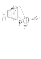
- FIG. 1 is a diagram schematically showing a first embodiment of a video presentation system according to the present invention capable of bidirectional communication between video and audio.
- the same video presentation system is also installed in a remote place beyond the wide area network 6, and communication using video and audio can be performed in real time between the video presentation systems.
- FIG. 1 will be described in detail.
- the embodiment of the video presentation system according to the present invention is executed by the computer 4, and video / audio processing is performed by the function of the computer 4.
- an information processing apparatus such as a PC can be applied.
- the computer 4 includes a display device 1 such as a liquid crystal display for displaying a video of a remote user 7 and electronic data 8 working with a remote partner, and a voice for reproducing the remote voice.
- the playback device 3 is connected.
- the computer 4 is for receiving video and audio information transmitted from a remote place and presenting the video and audio to the display device 1 and the audio reproduction device 3.
- a multimedia information acquisition device 2 that acquires user's video and audio at once.
- the multimedia information acquisition device 2 for acquiring video and audio does not necessarily have to be integrated, and a configuration in which video acquisition and audio acquisition are separated is also possible.
- the multimedia information acquisition device 2 may be configured by a microphone and a photographing device (camera), a microphone for acquiring sound may be placed near the user, and only the photographing camera may be installed at the top of the display device 1.
- the multimedia information acquisition apparatus 2 includes a plurality of, for example, two cameras.
- the multimedia information acquisition device 2 is connected to a computer 4 for presenting video and audio from the remote location.
- the computer 4 also performs transmission control for transmitting video and audio to a remote place separately from the processing on the receiving side. Further, the computer 4 is connected to an operation device 5 such as a keyboard, so that a user can input information such as a work form and change attributes of the electronic work object, and can control the system. Is possible.
- the computer 4 is connected to the same remote video presentation system via the network 6 and can transmit and receive video and audio. By using this video presentation system, the user 9 can communicate with the user of the system installed at a remote place while watching the electronic data 8 in real time.
- the video and audio signals acquired by the multimedia information acquisition apparatus 2 including a camera and a microphone are taken into the transmission apparatus 101 inside the video / audio processing apparatus 100.
- the video / audio processing apparatus 100 is an apparatus equivalent to the computer 4 in FIG.
- signal processing for transmission to a remote place is performed.
- Video and audio signals sent from a remote location via the wide area network 6 are taken into the receiving device 104 inside the video / audio processing device 100.
- the video signal is input to the video processing device (reception side) 105 in the reception device 104, and the audio signal is input to the audio processing device (reception side) 106.
- These video signals and audio signals are subjected to signal processing in such a manner that video and audio can be reproduced, and are output to the multimedia information presentation apparatus 10 including a display (display device) and a speaker.
- the video / audio processing device 107 is the video / audio processing device 100
- the reception device 109 is the reception device 104
- the transmission device 108 is the transmission device 101
- the multimedia information presentation device 12 is the multi-media.
- the multimedia information acquisition apparatus 11 and the multimedia information acquisition apparatus 11 correspond to the media information presentation apparatus 10 and the multimedia information acquisition apparatus 2, respectively.
- the photographing devices 2a and 2b are devices included in the multimedia information acquisition device 2 and shoot including the user 9 who uses this video presentation system.
- the imaging devices 2a and 2b can use general-purpose imaging devices such as Web cameras and HD (High-Definition) resolution imaging cameras, such as lenses, exposure adjustment mechanisms, and CCD (Charge-Coupled Device). Image pickup device components.
- the photographing devices 2a and 2b are connected to the video / audio processing device 100 via external input terminals (I / F) 200 and 201, respectively.
- I / F external input terminals
- the CCD generates and outputs a signal corresponding to the amount of received light received.
- the signal generated by the CCD is taken into the inside of the video processing device (transmission side) 102 as an image signal (video signal) after being subjected to predetermined signal processing for the camera.
- the imaging devices 2a and 2b acquire videos in synchronization with each other at regular intervals to handle moving images, and sequentially supply video signals to the video processing device (transmission side) 102.
- the video model generation unit 202 inputs videos acquired by the imaging device 2 a and the imaging device 2 b having different physical positions via the external input terminal (I / F) 200 and the external input terminal (I / F) 201.
- a parallax image signal is generated using a frame (image) signal (images 2a and 2b) taken out at a certain time.
- the parallax image signal uses a frame at a certain time (image signal: I base (x, y)) of the imaging device 2a as a reference image, and the frame (image signal: I ref (x, y) of the imaging device 2b at the same time as this. )) And the corresponding points of the pixels by the block matching method.
- the image signal of the imaging device 2b is referred to as a reference image.
- the video model generation unit 202 divides the reference image into blocks of a predetermined size when performing block matching.
- the size of the division is, for example, 16 pixels ⁇ 16 pixels.
- An index value between the divided block and the reference image is calculated for each area, and an area where the calculated index value is minimum is found (corresponding point).
- the video model generation unit 202 shifts the divided blocks of the reference image in units of pixels and calculates corresponding points in all pixels.
- the index value used in block matching only needs to indicate the correlation or similarity between image signals.
- the video model generation unit 202 uses, for example, the absolute value sum (SAD) of the difference between the luminance value of the pixel included in the divided block and the luminance value in a certain region of the reference image.
- SAD absolute value sum
- the SAD between a block (for example, a size of N ⁇ N pixels) divided from the reference image signal and the block of the reference image signal is expressed by the following expression.
- I base (i 0 + i, j 0 + j) is a luminance value at the coordinates (i 0 + i, j 0 + j) of the reference image, and (i 0 , j 0 ) is a processing target pixel coordinate for parallax calculation.
- I ref (i 0 + i + p, j 0 + j) is a luminance value at the coordinates (i 0 + i + p, j 0 + j) of the reference image, and p is based on the center coordinates (i 0 , j 0 ) of the divided block.
- the video model generation unit 202 calculates SAD (p) for each parameter p in block matching, and finds p that minimizes SAD (p).
- p represents the parallax from the base image to the position of the divided block and the reference area.
- the right side Is a function for extracting a p (parallax) value that minimizes the evaluation formula (the formula in ⁇ ).
- the video model generation unit 202 can obtain a parallax image in units of pixels.
- the video model generation unit 202 converts the calculated parallax image into a depth map indicating the actual distance using Expression (3).
- z is the depth value
- d is the parallax
- f and b are the focal length of the camera and the baseline distance between the cameras, respectively
- ⁇ d is the camera offset.
- the video model generation unit 202 generates depth information (three-dimensional model) in camera coordinates from the obtained depth map.
- the camera coordinates are a coordinate system unique to the photographed camera. Before that, it is necessary to convert the depth map obtained by Expression (3) from the image coordinate system X img to the camera coordinate system X cam .
- the image coordinate system is a coordinate system for handling image pixels.
- the conversion formula is as follows.
- Equation (4) Represents a homogeneous coordinate of the image coordinate system X img and is a three-dimensional coordinate (i, j, 1) obtained by adding one dimension to the two-dimensional image coordinate (i, j).
- a homogeneous coordinate is generally a way of taking a coordinate that expresses a space by a ratio of these dimensions by raising the dimension of the space by a first order.
- A is a matrix for converting a planar image of the camera coordinate system projected onto the imaging surface of the reference camera into the image coordinate system, and is called an internal matrix of the camera.
- a -1 indicates the inverse matrix.
- the internal matrix is a matrix including parameters (internal parameters) indicating the camera characteristics of the photographing apparatus, and is specifically as follows.
- f is the focal length
- (u 0 , v 0 ) is the coordinates of the image center
- k u and k v are scale factors in the u-axis (x-axis) and v-axis (y-axis) directions
- k s is a right angle. It is a parameter that represents distortion that does not maintain the property.
- J) is z
- the coordinates of the point m c in the projection source three-dimensional space are the triangle on the plane represented by the x c axis and the z c axis shown in FIG. 4, and the y c axis. and it consists of geometrically dissimilar triangles as follows in the plane on representable z c-axis.
- the video model generation unit 202 subsequently performs coordinate system conversion. Specifically, it is necessary to convert the coordinate system of the camera photographed by the photographing apparatus into a common coordinate system (hereinafter, world coordinate system X world ) handled by the present system.
- the world coordinate system is based on the center of the display device of FIG. 1 as the origin, the positive direction of the x axis in the right direction toward the display surface, the positive direction of the y axis in the upper direction of the display surface, and the depth from the display surface.
- the z-axis is the positive direction in the direction of.
- the transformation of the coordinate system can generally be performed by the following formula.
- X from the pre-conversion coordinates, X-to represent the coordinate system after conversion, R and T is a matrix showing the translational and rotational to the coordinate system after the change from the coordinate system before the conversion.
- the rotation and translation matrix is as follows.
- ⁇ x , ⁇ y , and ⁇ z indicate rotations about the X axis, the Y axis, and the Z axis, respectively.
- T x , T y , and T z indicate translations in the X-axis direction, the Y-axis direction, and the Z-axis direction, respectively.
- the matrix A, matrix R, and matrix T representing the camera characteristics and position can be generally obtained by camera calibration.
- the video model generation unit 202 can acquire a position in the three-dimensional space in the world coordinate system, and can generate a video model.
- the video model is composed of three-dimensional depth information (position information) and video (texture) information to be pasted thereon.
- the process of attaching a texture to depth information is also called texture mapping.
- Electronic data used in the collaborative work is stored in an external storage device / external server 203 connected to the video / audio processing apparatus 100, and is sent to the electronic data model generation unit 205 through an external input terminal (I / F) 204. Entered.
- the external storage device / external server is connected to a network and can be referred to from a video presentation system installed at a remote location.
- the electronic data model generation unit 205 generates an electronic data model based on the reference information (position, size, orientation) of the input electronic data, and outputs the electronic data model to the video / data synthesis unit 206.
- Electronic data is an office document that can be handled by a computer and is composed of text information by text or visual information such as images (video) and figures.
- an electronic data model is formed by a rectangular surface.
- the electronic data model is a combination of two minimum unit triangles (polygons) having three-dimensional position information (joining the long sides of the triangles) and pasting the image (video) of the office document. Model. Note that the position and angle of the electronic data may be varied during system operation by an electronic data control method described later.
- the reference setting can be prepared for each work style and user position described later, and can be switched according to the work content.
- the video / data composition unit 206 and the viewpoint generation unit 207 have a three-dimensional model processing function for processing model data in the world coordinate system, and more specifically, a GPU (3G model) that handles a three-dimensional model such as CG.
- the function can be realized by Graphics (Processing Unit).
- the video / data synthesizing unit 206 uses a common 3DCG rendering technology realized by a GPU to share a video model input from the video model generating unit 202 and an electronic data model input from the electronic data model generating unit 205 with a common coordinate system ( Place them in the world coordinate system) and synthesize each other.
- Scenes are formed by placing them on the screen, and images (electronic data pictures) taken directly on those surfaces are pasted, or images (electronic data pictures) are projected onto those surfaces from the shooting position.
- images electronic data pictures
- images electro-electronic data pictures
- the viewpoint generation unit 207 receives a model obtained by synthesizing video and electronic data from the video / data synthesis unit 206, and assumes a user position assumed in the calculated world coordinate system by a general 3DCG rendering technique realized by a GPU.
- a virtual camera virtual viewpoint
- the viewpoint generation unit 207 can cut out an image viewed from the viewer position assumed by the view conversion process.
- the view conversion process is to convert from the world coordinate system to coordinates based on the virtual camera placed at the observer position.
- V (r z , u z , ⁇ z )
- P (x, y, z)
- a perspective projection process is performed so that a distant view is small and a close view looks large with respect to the view-converted scene.
- two projection planes are introduced to a place close to the imaging device (front projection plane) and a far place (rear projection plane), and set to have a weight shape with the origin of the imaging device as the center.
- front projection plane front projection plane
- far place far place
- the projected coordinate system is expressed by the following matrix: Can be converted to
- conversion from the projected coordinate system to the screen coordinate system is performed for display on the display device.
- conversion is performed so that the upper left of the display device is the origin and the direction of the Y axis is reversed.
- the transformation matrix is as follows.
- an image viewed from the user's position is generated by the 3DCG rendering technology.
- FIG. 5 is a view (top view) of the entire system as viewed from above when the present system is used like a general face-to-face video conference system.
- reference numerals 500 and 501 denote video presentation systems including the configurations 1 to 5 shown in FIG.
- Reference numeral 500 denotes a video presentation system on the user 9 side shown in FIG. 1
- reference numeral 501 denotes a video presentation system installed at a remote place.
- the users are 9 and 7, and 7 is a user in a remote place.
- the systems are connected via a network 6 or the like so that they can communicate with each other.
- 504 and 505 show the world coordinate system X World_B each world coordinate system X World_A the side of the user 9 system and the user 7 a system perspective.
- the world coordinate system X world_A has a positive x-axis direction in the right direction toward the display surface, a positive z-axis direction toward the back of the display surface, and a positive y-axis direction (not shown). Assume that you are heading upward.
- the world coordinate system X world_B is based on the direction in which the user 7 is facing the display as a reference, the right direction (left direction in the drawing) of the display is the positive direction of the x axis, and the back direction of the display surface (drawing). , The downward direction) is the positive direction of the z-axis, and the positive direction of the y-axis (not shown) is upward.
- FIG. 6 illustrates a work form related to the present invention (positional relationship between a user and electronic data).
- FIG. 6 schematically shows a positional relationship in which a user 9 and a user 7 are next to each other and can see the work 600 (electronic data explicitly shown) from each other.
- FIG. 7 is a diagram schematically showing an image of a remote place shown on the display device when the positional relationship of FIG. 6 is realized.
- 7A is an image viewed by the user 9
- FIG. 7B is an image viewed by the user 7.
- the work 600 is positioned on the left side and the user 7 is positioned on the right side. Therefore, in the remote place image 506 viewed by the user 9, the work 600 is seen on the left, and the user 700's image 700 is seen on the right. On the other hand, for the user 7, the work 600 is on the right side and the user 9 is on the left side. Accordingly, in the remote place image 507 viewed by the user 7, the work 600 is seen on the right, and the image 701 of the user 9 is seen on the left side. As described above, by presenting the video shown in FIG. 7, the user can communicate while viewing the common electronic data and the video of the other party between the remote locations in the positional relationship shown in FIG.
- FIG. 7 a method of generating the viewpoint video as shown in FIG. 7 will be described with reference to FIG. First, it is necessary to clarify the positional relationship between users. This is because the user is at two points and, as shown in FIG. 6 or FIG. 7, the other party's video and electronic data in the presented video depending on whether the user is the user 9 or the user 7. This is because the display positions of are different.
- a method of determining the positional relationship between users for example, there is a method of determining both positions (which user in FIG. 6 is) in advance.
- the user can set the positions of each other according to the user display shown in FIG. 9 using the operation device 5 connected to the video / audio processing device 100.
- the setting result is held in the CPU 208 inside the video / audio processing apparatus 100.
- the CPU 208 uses a communication means (not shown) and cooperates with a remote video presentation system so that the setting value shown in FIG. 9 becomes exclusive (the item selected by one cannot be selected by the other party). You may control as follows.
- both positions are clarified.
- the image of the remote place displayed on the system 501 on the user 7 side is the image on the user 9 side.
- the video acquisition method is based on the assumption that the user 7 exists on the side of the user 9 and the system 500 so that the positional relationship shown in FIG. Get installed. That is, it can be realized by assuming that a remote user who does not actually exist is next to the user and transmitting the video taken from the user to the other party. For this purpose, it is necessary to convert each user's position into a virtual position in the other system, that is, to convert the coordinate system of one system into the coordinate system of the other system. By this conversion, the position in the coordinate system of the other system can be handled as the same coordinate system.
- the virtual position of the user 7 in the system on the user 9 side that is, the user 7 It is possible to calculate the camera installation position for acquiring the video to be sent to the side system.
- the system 500 and the system 501 are not physically connected, and the two coordinate systems cannot be associated (the physical positional relationship serving as a reference for converting the coordinate system is unclear).
- the coordinate data conversion is realized by associating both coordinate systems by using the commonly used electronic data 600 as a reference for the coordinate system conversion.
- the method for acquiring the image of the remote place displayed on the system 500 on the user 9 side is the same.
- the CPU 208 stores the basic information of the electronic data arranged in the world coordinate system set in the video presentation system (X world_A (504 in the case of the system 500 in FIG. 8, X world_B (505) in the system 501)). Using the position in each world coordinate system (805 for the 500 system, 806 for the 501 system) and its direction vector (807 for the 500 system, 808 for the 501 system), the following method is used. Decide the camera installation position to acquire video for the remote system.
- the CPU208 converts the world coordinate system X world_B of the remote system, via the coordinate system of the electronic data, the coordinate system X world_A of the system to be used.
- the three-dimensional position 805 of the electronic data center in the coordinate system X world_A of the system 500 is P E_A
- the direction vector 807 is ⁇ H E_A
- the three-dimensional position 806 of the electronic data center in the coordinate system X world_B of the system 501 is P E_B
- the direction vector 808 is set to ⁇ H E_B .
- the CPU 208 temporarily converts the coordinate system X world_B of the system 501 into a coordinate system of electronic data in the system 501 using Expression (7).
- the rotation matrix RW_BE_B and the translation matrix TW_BE_B applied to Expression (7) are obtained as follows.
- Rotation matrix R W_BE_B is rotated from the coordinate system X World_B system 501 to coordinate system of the electronic data 600, the same as the rotation in the direction that is oriented from the direction facing the display device of the system 501 of the electronic data 600 It is.
- the orientation of the electronic data 600 is ⁇ H E_B.
- the rotation angle RW_BE_B is calculated by substituting the above rotation angle into Expression (8).
- the translation matrix T W_BE_B is composed of vectors from the origin OW_B of the coordinate system X world_B of the system 501 toward the center position P E_B of the electronic data 600, and is expressed by the following equation.
- the CPU 208 obtains a rotation matrix R E_AW_A and a translation matrix T E_AW_A for converting the electronic data coordinate system into the world coordinate system X world_A in the system 500 in the same manner as the above method.
- the CPU 208 converts the coordinate system of the remote system 501 to the coordinate system of the system 500 using the following formula.
- CPU 208 may convert the coordinates in the world coordinate system X World_B in remote system 501, the coordinates in the coordinate system X World_A system 500 utilized.
- the CPU 208 converts the position of the user 7 in the remote place according to the equation (14), and installs a camera that acquires an image for the remote place system at the converted coordinate position.
- the CPU 208 transmits the video acquired by the camera to the remote system 501.
- the positions of the users 9 and 7 can be set by an appropriate viewing distance, for example, 3H (three times the vertical length of the display surface).
- a device for tracking the position of the user may be mounted, and the user position may be calculated in real time.
- a video of a viewpoint that allows users to see common electronic data in a positional relationship such that a remote person is next to each other is obtained by a simple method without setting the three-dimensional position. can do. By transmitting this video to both sides, it is possible to communicate in the above positional relationship.
- the viewpoint control may be set only once at the start of the system, or may be changed from time to time. Note that the shooting angle of view of the virtual camera need not be changed if the above system is known, that is, if the size of the display device can be limited. In addition, when the size of the display device changes for each system, a mechanism may be provided to change the shooting angle of view according to the display device of the other party.
- FIGS. 10 to 14 are flowcharts showing processing performed by the video / audio processing apparatus (video processing) 100 according to the present embodiment. In the following flowchart and the description thereof, the processing of the audio signal is described only where necessary.
- the video / audio processing apparatus (video processing) 100 starts system processing by a control unit that controls the entire system (not shown), the process proceeds to step S100.
- Step S100 The video / audio processing device (video processing) 100 uses the control unit to perform processing for communication with the processing for monitoring the operation of the entire system (the processing on the left side of FIG. 10, S101 to S104). (The processing on the right side of FIG. 10, S105 to S109) is started simultaneously. When both processes are started, the process proceeds to steps S101 and S105.
- Step S101 The video / audio processing device (video processing) 100 always monitors whether or not the system has been terminated by the control unit, and if not, repeats the processing of step S101. If completed, the process proceeds to step S102.
- Step S102 The video / audio processing device (video processing) 100 monitors the state of a thread to be executed in the process for performing communication by the control unit, and proceeds to step S103 if the thread is being executed. If all threads have been completed, the process proceeds to step S104.
- Step S103 In the video / audio processing apparatus (video processing) 100, the control unit forcibly terminates the thread being executed in the process for performing the communication, and the process proceeds to step S104.
- Step S104 The video / audio processing apparatus (video processing) 100 confirms that all processes are stopped by the control unit, and ends the system. Next, a process for performing communication will be described.
- Step S105 The video / audio processing device (video processing) 100 monitors whether or not communication with a remote place can always be started by the control unit, and if the communication can be started, step S106. If it is not ready to start communication, the process of step S105 is repeated.
- Step S106 In the video / audio processing apparatus (video processing) 100, the control unit starts a data transmission thread to be described later, and proceeds to step S107.
- Step S107 The video / audio processing apparatus (video processing) 100 starts a data reception thread described later by the control unit, and proceeds to step S108.
- Step S108 The video / audio processing device (video processing) 100 starts an electronic data control thread, which will be described later, by the control unit, and proceeds to step S109.
- Step S109 The video / audio processing apparatus (video processing) 100 always monitors the state of the started thread by the control unit, and if it is detected that the processing of all threads is completed, the step Returning to S105, the above process is repeated. On the other hand, if all the monitored threads have not ended, the process returns to step S109 to repeat the process.
- Step S200 The video processing apparatus (transmission side) 102 generates frame information to be transmitted by a transmission frame information generation process to be described later, and proceeds to step S201.
- Step S201 The transmission control unit 209 in the video processing apparatus (transmission side) 102 compresses the generated transmission frame information into a code with a smaller data amount (for example, the international standard video compression standard H. H.264 or the like), and the process proceeds to step S202.
- Step S202 The transmission control unit 209 in the video processing apparatus (transmission side) 102 packs the encoded video signal and audio signal in cooperation with the audio processing apparatus (transmission side) 103 in FIG. packing) and the process proceeds to step S203.
- Step S203 The video / audio processing apparatus 100 transmits the generated code data to the remote video presentation apparatus via the network. Thereafter, the process proceeds to step S204.
- Step S204 The video / audio processing apparatus 100 always monitors whether or not the communication is to be ended by the control unit. If it is to be ended, the process proceeds to step S205. If not, the process returns to step S200 to repeat the above processing. .
- Step S205 The video / audio processing apparatus 100 ends the data transmission thread.
- Step S300 The video processing device (transmission side) 102 takes in the video (frame) captured by the imaging devices 2a and 2b via the external input terminals (I / F) 200 and 201. Then, it progresses to step S301.
- Step S301 The video model generation unit 202 generates a video model based on the input multi-image. Thereafter, the process proceeds to step S302.
- Step S302 The electronic data model generation unit 205 generates electronic data model information based on the latest electronic data attribute information generated by an electronic data control thread described later. Thereafter, the process proceeds to step S303.
- Step S303 The video / data synthesis unit 206 synthesizes the video model input from the video model generation unit 202 and the electronic data model input from the electronic data model generation unit 205 in the world coordinate system, and proceeds to step S304.
- Step S304 The viewpoint generation unit 207 generates an image (frame) of the viewpoint according to the present invention based on the combined model information input from the video / data combination unit 206, and the process proceeds to step S305.
- the viewpoint generation unit 207 outputs the generated frame signal to the transmission control unit 209, and ends the transmission frame information generation process.
- the data reception thread is activated by the system process.
- the reception control unit 212 inside the video processing apparatus 105 receives the encoded data transmitted from the video presentation system at a remote location via the network. Then, it progresses to step S401.
- the reception control unit 212 in the video processing device 104 cooperates with a reception control unit (not shown) in the audio processing device 106 to convert the received encoded data into video encoded data and audio. Divide into encoded data. Thereafter, the process proceeds to step S402.
- Step S402 The reception control unit 212 inside the video processing device 104 performs a process opposite to the compression on the video encoded data, and restores the original signal having a large amount of data. Thereafter, the process proceeds to step S403.
- Step S403 The reception control unit 212 writes the restored image signal in the display memory 213.
- the display device 1 periodically reads out the image signal written in the display memory 213 and displays it on the screen. Thereafter, the process proceeds to step S404.
- Step S404 The video / audio processing apparatus 100 always monitors whether or not the communication is to be ended by the control unit. If it is to be ended, the process proceeds to step S405. If not, the process returns to step S400 to repeat the above processing. . (Step S405) The video / audio processing apparatus 100 ends the data reception thread.
- Step S500 The CPU 208 in the video processing device (transmission side) 102 always monitors an attribute (described later) change of electronic data set by the user using the operation device 5. If the attribute is changed, the CPU 208 proceeds to Step S501. move on. If the attribute is not changed, the process of step S500 is repeated.
- Step S501 The CPU 208 updates the attribute information of the electronic data, outputs the latest attribute information to the electronic data model generation unit 205, and reflects the contents in the electronic data model generation process. Thereafter, the process proceeds to step S502.
- Step S502 The CPU 208 transmits the updated electronic data attribute information to the remote video presentation apparatus by another means via a network (not shown). Thereafter, the process proceeds to step S503.
- Step S503 The video / audio processing apparatus 100 always monitors whether or not the communication is to be ended by the control unit. When the communication is to be ended, the process proceeds to step S504. Otherwise, the process returns to step S500 to repeat the above processing. . (Step S504) The video / audio processing apparatus 100 ends the electronic data control thread.
- the electronic data attribute information generated in step S501 in FIG. 14 will be described with reference to FIG.
- the electronic data attribute information is information indicating, for example, the three-dimensional position of the electronic data, the orientation and the size of the surface, and is information capable of arranging the electronic data at the three-dimensional position in the world coordinate system.
- Transmission frame information generated by the transmission frame information generation processing of FIG. 12 will be described with reference to FIG.
- the transmission frame information is, for example, information representing one image composed of pixel number (horizontal direction): width and pixel number (vertical direction): height and pixel information.
- the unit 212 may be realized by a computer.
- the program for realizing the control function may be recorded on a computer-readable recording medium, and the program recorded on the recording medium may be read by a computer system and executed.
- the “computer system” here is a computer system and DSP (digital signal processor) built in the video / audio processing apparatus, and includes hardware such as an OS and peripheral devices.
- the “computer-readable recording medium” means a storage device such as a flexible disk, a magneto-optical disk, a portable medium such as a ROM and a CD-ROM, and a hard disk incorporated in a computer system.
- the “computer-readable recording medium” is a medium that dynamically holds a program for a short time, such as a communication line when transmitting a program via a network such as the Internet or a communication line such as a telephone line, In such a case, a volatile memory inside a computer system serving as a server or a client may be included and a program that holds a program for a certain period of time.
- the program may be a program for realizing a part of the functions described above, and may be a program capable of realizing the functions described above in combination with a program already recorded in a computer system.
- a part or all of the video / audio processing apparatus 100 in the above-described embodiment may be realized as an integrated circuit such as an LSI (Large Scale Integration).
- LSI Large Scale Integration
- Each functional block of the video / audio processing apparatus 100 may be individually made into a processor, or a part or all of them may be integrated into a processor.
- the method of circuit integration is not limited to LSI, and may be realized by a dedicated circuit or a general-purpose processor. Further, in the case where an integrated circuit technology that replaces LSI appears due to progress in semiconductor technology, an integrated circuit based on the technology may be used.
- Reception apparatus 202 ... Video model generation part, 203 ... External server, 205 ... Electronic Data model generation unit, 206 ... Video / data synthesis unit, 207 ... View point generation unit, 208 ... CPU, 209 ... Transmission control unit, 212 ... Reception control unit, 213 ... Display memory, 500 ... system, 501 ... system 506 ... image, 507 ... image, 600 ... work product, 700 ... image, 701 ... image.
Landscapes
- Engineering & Computer Science (AREA)
- Theoretical Computer Science (AREA)
- Physics & Mathematics (AREA)
- Computing Systems (AREA)
- Geometry (AREA)
- Computer Graphics (AREA)
- General Physics & Mathematics (AREA)
- Processing Or Creating Images (AREA)
- Two-Way Televisions, Distribution Of Moving Picture Or The Like (AREA)
Abstract
遠隔地作業者が隣にいるような位置関係で共通の電子作業オブジェクトを見ながら作業を行うことができるようにする。映像提示システムは、撮影装置(2a).(2b)によって取得された撮影映像を入力し、その撮影映像に電子データを合成して送受信することにより、遠隔地間のコミュニケーションを可能とする。本システムは、撮影する範囲の奥行き情報を基に、奥行き情報と映像情報とからなる映像モデルを生成する映像モデル生成部(202)と、入力した電子データの基準情報に基づいて電子データモデルを生成する電子データモデル生成部(205)と、共通の座標系を設けて、映像モデルと電子データモデルを共通の座標系内で合成する映像・データ合成部(206)と、共通の座標空間に仮想的な視点を設置して、該視点の映像を生成する視点生成部(207)とを有し、視点生成部で取得した映像を送信する。
Description
本発明は、映像提示システム、映像提示方法、プログラム及び記録媒体に関し、より具体的には、撮影画像に対してリアルタイムに電子データを合成表示することで、遠隔地のシステム間で、コミュニケーションをとって共同作業を行うことができるようにした映像提示システム、及び該システムの機能を実現する映像提示方法とプログラム及び記録媒体に関する。
複数の作業者によるフェイスツーフェイスの共同作業には様々な形態がある。例えば、フェイスツーフェイスの共同作業として、実在の物を使った作業(モックアップを用いたプロダクトデザイン確認、作業リーダによる製造装置の使用方法に関するレクチャー等)や、作業者がお互いに横に座りながら、あるいは側に立ち、共通の画面を見ながら計算機を使った作業(ペアプログラミング、作業画面を使った状況報告等)等があり、これらの作業は頻繁に行われている。
撮影された実写映像に計算機で利用することができる電子データを合成表示することで、上記実際の作業に近いコミュニケーションを遠隔地間で実現することができる。さらに撮影された実写映像の3次元的な空間や位置関係を考慮して電子データを合成できると、2次元平面に単純に電子データを貼り付ける場合に比べて、視認性や物体位置認識効果を高めることができる。これらの研究は、拡張現実(AR:Augmented Reality)・複合現実(MR:Mixed Reality)と呼ばれ、多くの実施例がある。
例えば、特許文献1には、送信者側の映像を受信者側に転送し、仮想空間内で送信者と受信者のアバターと呼ばれる人物映像を仮想空間の背景画像と合成しリアルタイムに表示することで、コミュニケーションや協調作業を行うための装置について開示されている。送信者の映像は、送信者と受信者の仮想空間内の位置関係から、複数の角度に設置された撮影装置の中から適切な位置の映像が選択されて伝送されるような構成になっている。しかし、双方の利用者は仮想空間内の位置を考慮して、アバターを適切に配置する必要がある。
例えば、非特許文献1には、利用者の前に設置された特殊な表示面、具体的には偏光された光がその後方に透過できない半透過の投影面を設置し、上部より偏光された遠隔地の映像をその投影面に映し出す。さらに、半透過投影面の背後に撮影カメラを設置し、透過してきた利用者の映像を撮影し遠隔地に送信する。また、遠隔地の映像内に電子データを重畳することで、双方の間に電子的な作業オブジェクトを表示させて協調作業を行うための装置について開示されている。
"Integration of Interpersonal Space and Shared Workspace: ClearBoard Design and Experiments" ACM Transaction on Information Systems,Vol.11,No.4,October 1993,Pages349-375
特許文献1で開示されている方法は、利用者自身が、仮想空間内の位置や向いている方向を常に意識する必要があることと、双方が同一の役割で利用できるシステムになっていないという課題がある。
非特許文献2で開示されているシステムは、特殊な投影面が必要であり、かつ投影面の上部に偏光した映像を投影するための装置と投影面の後方に利用者を撮影する装置を設置する必要があり、システムとして非常に大がかりになる課題がある。
非特許文献2で開示されているシステムは、特殊な投影面が必要であり、かつ投影面の上部に偏光した映像を投影するための装置と投影面の後方に利用者を撮影する装置を設置する必要があり、システムとして非常に大がかりになる課題がある。
本発明は、上記特許文献1の課題にあるような、利用者が仮想的な3次元空間位置を考慮する必要なく、共通に利用する電子データの3次元的な位置を介して、双方の利用者の位置及び表示装置の相対的な位置を確定させ、その情報に基づいて双方のシステムに送る映像を生成することで、遠隔地作業者が隣にいるような位置関係で共通の電子作業オブジェクトを見ながら作業を行うことができるようにすること、また、そのような作業を実現するシステムを汎用的なディスプレイや撮影装置を用いて実現することを目的とするものである。
上記課題を解決するために、本発明の第1の技術手段は、撮影装置によって取得された撮影映像を入力し、該入力した撮影映像に、画像として生成された電子データを加工して合成し、該合成した映像を送受信することにより、遠隔地間でコミュニケーションを行なうことを可能とした映像提示システムであって、撮影する範囲の奥行き情報と、該奥行き情報を基に該奥行情報に貼り付けた映像情報とからなる映像モデルを生成する映像モデル生成部と、電子データを入力し、該入力した電子データの位置、大きさ、向きの情報を含む基準情報に基づいて電子データモデルを生成する電子データモデル生成部と、共通の座標系を設けて、前記映像モデルと前記電子データモデルを共通の座標系内で合成する映像・データ合成部と、該映像・データ合成部で合成されたモデルを入力し、前記共通の座標空間に仮想的な視点を設置して、該視点の映像を生成する視点生成部と、該視点生成部で取得した映像を送信する送信部と、を有することを特徴としたものである。
第2の技術手段は、第1の技術手段において、前記視点生成部が、前記電子データの3次元的な位置と前記共通の座標系における利用者の相対的な位置関係に基づいて算出された視点位置の映像を生成することを特徴としたものである。
第3の技術手段は、第2の技術手段において、利用者による操作入力を受け付ける操作装置と、前記電子データの位置及び利用者の視点位置を設定するための表示画面を表示装置に表示させる制御手段とを有し、前記視点生成部は、前記表示画面に対する前記操作装置の操作入力に従って、前記電子データの3次元的な位置及び利用者の視点位置を決定することを特徴としたものである。
第4の技術手段は、第1~第3のいずれか1の技術手段において、利用者の3次元上の位置を計測する3次元位置計測装置を有し、前記視点生成部は、前記3次元位置計測装置による計測結果に従って、利用者の位置をリアルタイムに変更することを特徴としたものである。
第5の技術手段は、第1~第4のいずれか1の技術手段において、前記撮影装置を複数備え、前記映像モデル生成部が、複数の前記撮影装置で撮影された映像から視差画像を生成し、該生成した視差画像に基づいて撮影された対象のデプスを示すデプスマップを生成し、該デプスマップから前記撮影装置の固有の座標系における奥行き情報を生成し、該撮影装置の固有の座標系を前記映像提示システムで扱う共通座標系に変換して、奥行き情報と該奥行き情報に貼り付けた映像情報とからなる前記映像モデルを生成することを特徴としたものである。
第6の技術手段は、撮影装置によって取得された撮影映像を入力し、該入力した撮影映像に、画像として生成された電子データを加工して合成し、該合成した映像を送受信することにより、遠隔地間でコミュニケーションを行なうことを可能とした映像提示方法であって、撮影する範囲の奥行き情報と、該奥行き情報を基に該奥行き情報に貼り付けた映像情報とからなる映像モデルを生成する第1の過程と、電子データを入力し、該入力した電子データの位置、大きさ、向きの情報を含む基準情報に基づいて該電子データモデルを生成する第2の過程と、共通の座標系を設けて、前記映像モデルと前記電子データモデルを共通の座標系内で合成する第3の過程と、該第3の過程で合成されたモデルを入力し、前記共通の座標空間に仮想的な視点を設置して、該視点の映像を生成する第4の過程と、該第4の過程で取得した映像を送信する第5の過程と、を有することを特徴としたものである。
第7の技術手段は、撮影装置によって取得された撮影映像を入力し、該入力した撮影映像に、画像として生成された電子データを加工して合成し、該合成した映像を送受信することにより、遠隔地間でコミュニケーションを行なうことを可能とした映像提示装置のコンピュータに、撮影する範囲の奥行き情報と、該奥行き情報を基に該奥行き情報に貼り付ける映像情報とからなる映像モデルを生成する手順と、電子データを入力し、該入力した電子データの位置、大きさ、向きの情報を含む基準情報に基づいて該電子データモデルを生成する手順と、共通の座標系を設けて、前記映像モデルと前記電子データモデルを共通の座標系内で合成する手順と、該合成されたモデルを入力し、前記共通の座標空間に仮想的な視点を設置して、該視点の映像を生成する手順と、該生成された映像を送信する手順を実行させるための映像提示プログラムである。
第8技術手段は、第7の技術手段の映像提示プログラムを、コンピュータ読み取り可能に記録した記録媒体である。
遠隔コミュニケーションにおいて、双方がお互いに隣にいるような位置関係で、共通の電子データを見ながらコミュニケーションを行うことが可能になる。
以下、図面を参照しながら本発明の実施形態について説明する。
[実施形態1]
<システム構成>
図1は映像と音声を双方向通信できる本発明に係る映像提示システムの第1の実施形態を模式的に示す図である。広域のネットワーク6より先の遠隔地にも同じ映像提示システムが設置されており、映像提示システム間で、映像と音声を使ったコミュニケーションをリアルタイムに行うことができる。
[実施形態1]
<システム構成>
図1は映像と音声を双方向通信できる本発明に係る映像提示システムの第1の実施形態を模式的に示す図である。広域のネットワーク6より先の遠隔地にも同じ映像提示システムが設置されており、映像提示システム間で、映像と音声を使ったコミュニケーションをリアルタイムに行うことができる。
図1について詳しく説明する。本発明に係る映像提示システムの実施形態は、計算機4で実行され、計算機4の有する機能により映像・音声処理が行われる。計算機4は、例えばPCなどの情報処理装置を適用することができる。
計算機4には、遠隔地の利用者7の映像、及び遠隔地の相手と一緒に作業を行っている電子データ8を表示する液晶ディスプレイなどの表示装置1と、遠隔地の音声を再生する音声再生装置3とが接続される。計算機4は、遠隔地から伝送されてきた映像と音声の情報を受け取り、表示装置1と音声再生装置3に映像や音声を提示するためのものである。
計算機4には、遠隔地の利用者7の映像、及び遠隔地の相手と一緒に作業を行っている電子データ8を表示する液晶ディスプレイなどの表示装置1と、遠隔地の音声を再生する音声再生装置3とが接続される。計算機4は、遠隔地から伝送されてきた映像と音声の情報を受け取り、表示装置1と音声再生装置3に映像や音声を提示するためのものである。
表示装置1の上部には、利用者の映像と音声を一度に取得するマルチメディア情報取得装置2が設置されている。映像や音声を取得するためのマルチメディア情報取得装置2は必ずしも一体化している必要はなく、映像の取得と音声の取得を分離した装置で実現する構成も可能である。例えば、マルチメディア情報取得装置2をマイク及び撮影装置(カメラ)によって構成し、音声を取得するためのマイクを利用者の近くに置き、撮影カメラのみを表示装置1の上部に設置した構成としてもよい。また、マルチメディア情報取得装置2は、複数の、例えば2個のカメラを備えている。マルチメディア情報取得装置2は、上記遠隔地からの映像と音声を提示するための計算機4に接続されている。
計算機4は、上記受信側の処理とは別に、遠隔地に映像や音声を伝送するための送信制御も行っている。
また、計算機4には、キーボードなどの操作装置5が接続されており、利用者が作業形態等の情報を入力したり電子作業オブジェクトの属性を変更することが可能で、システムを制御することが可能である。
計算機4は、ネットワーク6を介して、遠隔地の同一の映像提示システムと繋がっており、映像や音声の送受信を行うことができる。利用者9はこの映像提示システムを利用することで、遠隔地に設置された同システムの利用者とリアルタイムに電子データ8を見ながらコミュニケーションを行うことができる。
また、計算機4には、キーボードなどの操作装置5が接続されており、利用者が作業形態等の情報を入力したり電子作業オブジェクトの属性を変更することが可能で、システムを制御することが可能である。
計算機4は、ネットワーク6を介して、遠隔地の同一の映像提示システムと繋がっており、映像や音声の送受信を行うことができる。利用者9はこの映像提示システムを利用することで、遠隔地に設置された同システムの利用者とリアルタイムに電子データ8を見ながらコミュニケーションを行うことができる。
<ブロック構成>
(システム基本ブロックの説明)
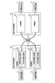
計算機4の内部で行われる基本の処理について、図2のブロック図を用いて説明する。図2において、広域のネットワーク6より左側が上記利用者9の側を示し、右側が遠隔地の側を示している。
(システム基本ブロックの説明)
計算機4の内部で行われる基本の処理について、図2のブロック図を用いて説明する。図2において、広域のネットワーク6より左側が上記利用者9の側を示し、右側が遠隔地の側を示している。
利用者9側の映像提示システムにおける送信機能についてはじめに説明する。カメラやマイクで構成されるマルチメディア情報取得装置2で取得された映像と音声の信号は、映像・音声処理装置100の内部にある送信装置101に取り込まれる。映像・音声処理装置100は、図1の計算機4と等価な装置である。ここでは、映像信号は送信装置101内の映像処理装置(送信側)102に、音声信号は音声処理装置(送信側)103に入力され、遠隔地に送信するための信号処理が施された後に、外部に出力され、広域のネットワーク6を経由して遠隔地に伝送される。
続いて、映像提示システムの受信機能について説明する。広域のネットワーク6を経由して遠隔地から送られてきた映像と音声の信号が、映像・音声処理装置100の内部の受信装置104に取り込まれる。映像信号は受信装置104内の映像処理装置(受信側)105に入力され、音声信号は音声処理装置(受信側)106に入力される。そしてこれら映像信号及び音声信号は、映像や音声を再現できる形に信号処理され、ディスプレイ(表示装置)やスピーカで構成されるマルチメディア情報提示装置10に出力される。
遠隔地の処理についても同様で、映像・音声処理装置107は映像・音声処理装置100に、受信装置109は受信装置104に、送信装置108は送信装置101に、マルチメディア情報提示装置12はマルチメディア情報提示装置10に、マルチメディア情報取得装置11はマルチメディア情報取得装置2に、それぞれ対応している。
<処理>
(映像・音声処理装置100の詳細説明)
映像・音声処理装置100について、図3のブロック図を用いて具体的に説明する。但し、音声処理については、支障がない限り説明を省略する。以下、上記利用者9が使用する映像提示システムにおいて、撮影された利用者の撮像画像に作業で扱う電子データを合成(重畳)した映像を遠隔地に伝送する流れと、遠隔地から送られてきた映像を受信して表示するまでの流れについて説明する。もう一方の遠隔地側の流れについては、利用者9のシステムと同じであるため説明は省略する。
(映像・音声処理装置100の詳細説明)
映像・音声処理装置100について、図3のブロック図を用いて具体的に説明する。但し、音声処理については、支障がない限り説明を省略する。以下、上記利用者9が使用する映像提示システムにおいて、撮影された利用者の撮像画像に作業で扱う電子データを合成(重畳)した映像を遠隔地に伝送する流れと、遠隔地から送られてきた映像を受信して表示するまでの流れについて説明する。もう一方の遠隔地側の流れについては、利用者9のシステムと同じであるため説明は省略する。
撮影装置2a、2bは、マルチメディア情報取得装置2に含まれる装置であり、本映像提示システムを使う利用者9を含めて撮影する。この撮影装置2a、2bは、WebカメラやHD(High-Definition)解像度の撮影カメラなどの汎用の撮像デバイスを利用することが可能で、レンズ、露光調整機構、CCD(Charge Coupled Device)など基本的な撮像デバイス構成要素を有している。撮影装置2a、2bは、それぞれ外部入力端子(I/F)200、201によって映像・音声処理装置100に接続されている。撮影装置2a、2bでは、撮影対象を含む視野からの光が、レンズ・露光調整機構を通してCCD上に結像される。CCDは入力された受光量に応じた信号を生成し出力する。
CCDで生成された信号は、カメラ用の所定の信号処理が施された後に、画像信号(映像信号)として映像処理装置(送信側)102の内部に取り込まれる。撮影装置2a、2bは、動画像を扱うため一定間隔で、お互いに同期して映像を取得し、逐次映像信号を映像処理装置(送信側)102に供給する。
映像モデル生成部202は、物理的に位置の異なる撮影装置2aと撮影装置2bで取得した映像を、外部入力端子(I/F)200と外部入力端子(I/F)201を介して入力し、ある時刻において取り出したフレーム(画像)信号(2a、2bの画像)を用いて、視差画像信号を生成する。視差画像信号は、撮影装置2aのある時刻のフレーム(画像信号:Ibase(x,y))を基準画像とし、これと同一時刻の撮影装置2bのフレーム(画像信号:Iref(x,y))との間で、ブロックマッチング法によって画素の対応点を求めることによって生成できる。この場合、撮影装置2bの画像信号を、参照画像と呼ぶ。
(視差画像生成)
映像モデル生成部202は、ブロックマッチングを行う際に、基準画像を所定の大きさのブロックに分割を行う。分割の大きさは、例えば16画素×16画素である。当該分割されたブロックと参照画像の間の指標値を領域毎に算出し、算出した指標値が最小となる領域を探し出す(対応点)。映像モデル生成部202は、基準画像の分割ブロックを画素単位でずらしていき、すべての画素において対応点を算出する。
映像モデル生成部202は、ブロックマッチングを行う際に、基準画像を所定の大きさのブロックに分割を行う。分割の大きさは、例えば16画素×16画素である。当該分割されたブロックと参照画像の間の指標値を領域毎に算出し、算出した指標値が最小となる領域を探し出す(対応点)。映像モデル生成部202は、基準画像の分割ブロックを画素単位でずらしていき、すべての画素において対応点を算出する。
ブロックマッチングで用いる指標値は、画像信号間の相関性や類似性を示すものであればよい。映像モデル生成部202は、例えば、分割されたブロックに含まれる画素の輝度値と参照画像のある領域における輝度値の差の絶対値総和(SAD;Sum of Absolute Difference)を用いる。基準画像信号から分割されたブロック(例えば、大きさがN×N画素)と参照画像信号のブロックとの間のSADは次の式で表される。

式(1)において、Ibase(i0+i,j0+j)は基準画像の座標(i0+i,j0+j)における輝度値、(i0,j0)は視差算出する処理対象画素座標を示す。Iref(i0+i+p,j0+j)は参照画像の座標(i0+i+p,j0+j)における輝度値で、pは当該分割されたブロックの中心座標(i0,j0)を基準としたx軸方向(水平方向)のシフト量(視差)である。撮影装置2aと撮影装置2bを水平になるように設置した場合、対応する画素は水平な直線上であり、y軸方向(垂直方向)のパラメータは削除できる。
映像モデル生成部202は、ブロックマッチングにおいて、パラメータp毎にSAD(p)を算出し、SAD(p)を最小とするpを探し出す。pは基準画像から当該分割されたブロックと当該参照領域の位置までの視差を表す。
映像モデル生成部202は、ブロックマッチングにおいて、パラメータp毎にSAD(p)を算出し、SAD(p)を最小とするpを探し出す。pは基準画像から当該分割されたブロックと当該参照領域の位置までの視差を表す。

式(2)において、右辺の

は、評価式({}内の数式)を最小にするp(視差)値を抽出する関数である。以上により、映像モデル生成部202は、視差画像を画素単位で求めることができる。
(デプスマップ生成)
映像モデル生成部202は、上記算出した視差画像を、式(3)を用いて実際の距離を示すデプスマップに変換する。
映像モデル生成部202は、上記算出した視差画像を、式(3)を用いて実際の距離を示すデプスマップに変換する。

ここで、zはデプス値、dは視差、fとbはそれぞれカメラの焦点距離とカメラ間のベースライン距離、Δdはカメラオフセットを示している。
(カメラ座標における3次元モデル生成)
次に、映像モデル生成部202は、得られたデプスマップから、カメラ座標における奥行き情報(3次元モデル)を生成する。カメラ座標とは、撮影したカメラ固有の座標系である。
その前に、式(3)で得られたデプスマップを、画像座標系Ximgから前記カメラ座標系Xcamに変換する必要がある。画像座標系とは、画像の画素を扱うための座標系である。その変換式は、以下の通りである。
次に、映像モデル生成部202は、得られたデプスマップから、カメラ座標における奥行き情報(3次元モデル)を生成する。カメラ座標とは、撮影したカメラ固有の座標系である。
その前に、式(3)で得られたデプスマップを、画像座標系Ximgから前記カメラ座標系Xcamに変換する必要がある。画像座標系とは、画像の画素を扱うための座標系である。その変換式は、以下の通りである。

式(4)において、

は画像座標系Ximgの斉次座標を表しており、2次元の画像座標(i,j)に1次元加えた3次元の座標(i,j,1)である。斉次座標とは、一般的に、空間の次元を1次上げ、これらの比によって空間を表現する座標の取り方である。
Aは、前記基準カメラの撮像面に投影された前記カメラ座標系の平面画像を前記画像座標系に変換するマトリクスであり、カメラの内部行列と呼ばれている。A-1は、その逆行列を示している。内部行列は、前記撮影装置のカメラ特性を示すパラメータ(内部パラメータ)を含むマトリクスで、具体的には以下のとおりである。
Aは、前記基準カメラの撮像面に投影された前記カメラ座標系の平面画像を前記画像座標系に変換するマトリクスであり、カメラの内部行列と呼ばれている。A-1は、その逆行列を示している。内部行列は、前記撮影装置のカメラ特性を示すパラメータ(内部パラメータ)を含むマトリクスで、具体的には以下のとおりである。
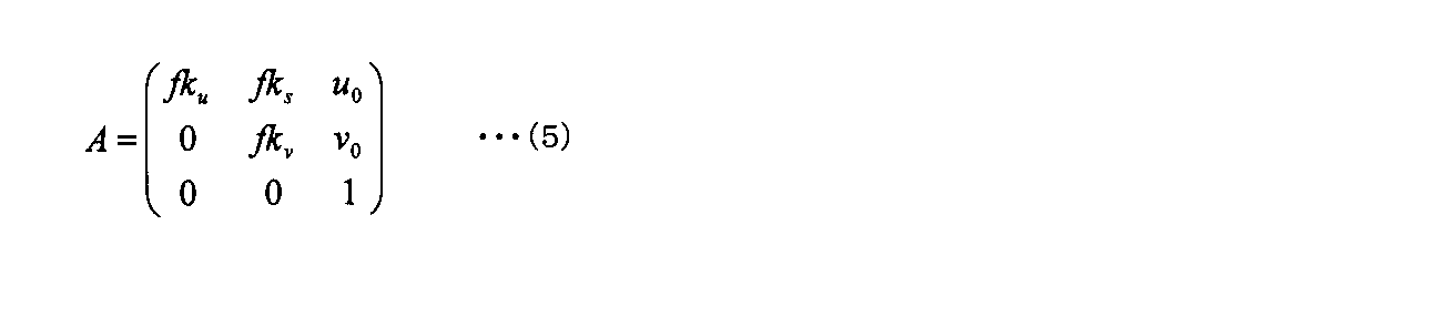
ここで、fは焦点距離、(u0,v0)は画像中心の座標、kuおよびkvはu軸(x軸)、v軸(y軸)方向のスケールファクタで、ksは直角性を保たないような歪みを表すパラメータである。
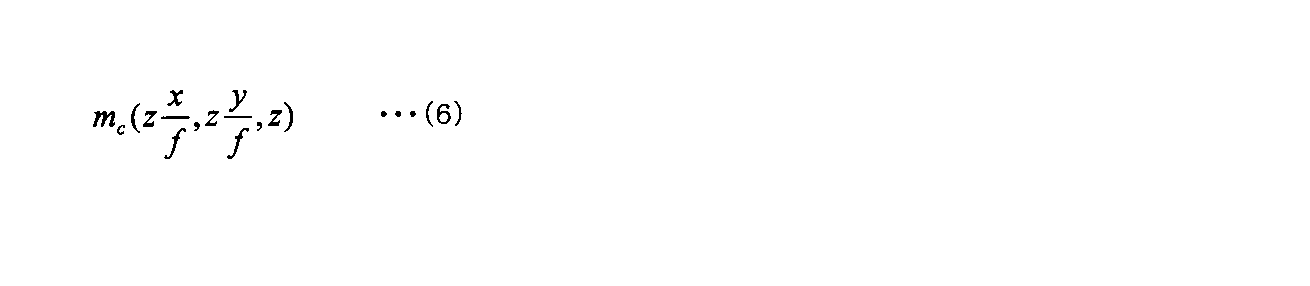
図4を用いて、3次元空間の奥行き情報を復元する方法について説明する。デプスマップ上のある座標(i,j)が、式(4)によってカメラ座標系の画像平面(z=f)上の1点m(x,y,f)に変換されたとし、座標(i,j)におけるデプス値がzである場合、投影元の3次元空間内の点mcの座標は、図4に示すxc軸とzc軸で表せる平面上にある三角形と、yc軸とzc軸で表せる平面上にある三角形の相似の関係から以下のようになる。
(ワールド座標における3次元モデル生成)
図3に戻り、映像モデル生成部202は、続いて座標系の変換を行う。具体的には、上記撮影装置で撮影されたカメラの座標系を、本システムで扱う共通の座標系(以下、ワールド座標系Xworld)に変換する必要がある。ワールド座標系は、図1の表示装置の中心を原点に、ディスプレイ面に向かって右の方向にx軸の正の方向、ディスプレイ面の上部の方向にy軸の正の方向、ディスプレイ面から奥の方向にz軸の正の方向とする。
座標系の変換は、一般的に以下の式によって行うことができる。
図3に戻り、映像モデル生成部202は、続いて座標系の変換を行う。具体的には、上記撮影装置で撮影されたカメラの座標系を、本システムで扱う共通の座標系(以下、ワールド座標系Xworld)に変換する必要がある。ワールド座標系は、図1の表示装置の中心を原点に、ディスプレイ面に向かって右の方向にx軸の正の方向、ディスプレイ面の上部の方向にy軸の正の方向、ディスプレイ面から奥の方向にz軸の正の方向とする。
座標系の変換は、一般的に以下の式によって行うことができる。

ここで、Xfromは変換前の座標系、Xtoは変換後の座標系を表し、RとTは変換前の座標系から変化後の座標系への回転と併進を示すマトリクスである。回転と併進のマトリクスを具体的に示すと、以下のとおりである。
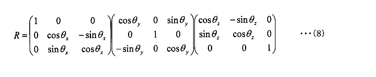
ここでθx、θy、θzは、それぞれX軸周り、Y軸周り、Z軸周りの回転を示す。
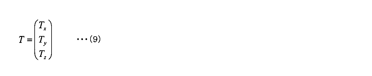
ここでTx、Ty、Tzは、それぞれX軸方向、Y軸方向、Z軸方向の併進を示す。
上記、カメラの特性や位置を表す行列A、行列Rや行列Tは、カメラ校正によって一般的に求めることができる。
上記、カメラの特性や位置を表す行列A、行列Rや行列Tは、カメラ校正によって一般的に求めることができる。
以上により、映像モデル生成部202は、上記ワールド座標系における3次元空間上の位置を取得でき、映像モデルを生成することができる。映像モデルとは、3次元的な奥行き情報(位置情報)と、それに貼り付ける映像(テクスチャ)情報で構成されるものである。テクスチャを奥行き情報に貼り付ける処理は、テクスチャマッピングとも呼ばれる。
図3に戻り、電子データを取得する方法について説明する。
共同作業で用いる電子データは、映像・音声処理装置100に接続された、外部記憶装置/外部サーバ203に格納されており、外部入力端子(I/F)204を通じて、電子データモデル生成部205に入力される。外部記憶装置/外部サーバは、ネットワークに接続されており、遠隔地に設置された映像提示システムからも参照することが可能である。
共同作業で用いる電子データは、映像・音声処理装置100に接続された、外部記憶装置/外部サーバ203に格納されており、外部入力端子(I/F)204を通じて、電子データモデル生成部205に入力される。外部記憶装置/外部サーバは、ネットワークに接続されており、遠隔地に設置された映像提示システムからも参照することが可能である。
電子データモデル生成部205は、入力した電子データの基準情報(位置、大きさ、向き)を基に電子データモデルを生成し、映像・データ合成部206に出力する。電子データは、コンピュータで扱うことができる、テキストによる文字情報、あるいは画像(映像)や図形などのビジュアル情報によって構成されたオフィスドキュメントである。一般的に、電子データモデルは、矩形状の面で形成される。具体的には、電子データモデルは、3次元の位置情報を有した最小単位の三角形(ポリゴン)を2枚組み合わせ(三角形の長辺を接合し)、上記オフィスドキュメントの画像(映像)を貼り付けたモデルである。
なお、電子データの位置や角度は、後述する電子データ制御方法によって、システム稼働中に可変しても良い。なお、基準設定については、後述する作業スタイルと利用者位置毎に準備し、作業内容に応じて切り替えることもできる。
なお、電子データの位置や角度は、後述する電子データ制御方法によって、システム稼働中に可変しても良い。なお、基準設定については、後述する作業スタイルと利用者位置毎に準備し、作業内容に応じて切り替えることもできる。
映像・データ合成部206及び視点生成部207は、前記ワールド座標系でモデルデータを処理するための3次元モデル処理機能を有しており、具体的にはCGなどの3次元モデルを扱うGPU(Graphics Processing Unit)によってその機能を実現することができる。
(3次元位置に基づいたレンダリング方法)
映像・データ合成部206は、GPUで実現される一般的な3DCGレンダリング技術によって、映像モデル生成部202から入力する映像モデルと電子データモデル生成部205から入力する電子データモデルを共通の座標系(ワールド座標系)内に配置させ、お互いを合成させる。
映像・データ合成部206は、GPUで実現される一般的な3DCGレンダリング技術によって、映像モデル生成部202から入力する映像モデルと電子データモデル生成部205から入力する電子データモデルを共通の座標系(ワールド座標系)内に配置させ、お互いを合成させる。
具体的には、供給される3次元位置を持った複数の平面、あるいは最小単位である三角形(ポリゴン)を複数組み合わせて表現する立体的な面を仮想的な3次元空間内(ワールド座標系)に配置することでシーンが形成され、さらに、それらの面に直接撮影した映像(電子データの絵)を貼り付けたり、あるいは撮影位置からそれらの面に向けて映像(電子データの絵)を投影(投影テクスチャリング)することで、3次元的な奥行き構造を持ったモデルに映像を貼り付けることができる。各モデル間の前後関係の処理(奥のオブジェクトが、手前のオブジェクトによって隠れる領域については表示させないための処理)は、GPUの機能によって実現される。
視点生成部207は、映像・データ合成部206から映像と電子データを合成したモデルを入力し、GPUで実現される一般的な3DCGレンダリング技術によって、上記算出したワールド座標系において想定する利用者位置(詳細は後述する)に仮想的なカメラ(仮想視点)を設置し、そのカメラによって3次元空間に再現されたシーンを撮影する。
具体的には、視点生成部207は、ビュー変換処理によって想定する観察者位置から見た画像を切り出すことができる。ビュー変換処理は、ワールド座標系から観察者位置に置かれた仮想カメラを基準とする座標に変換することである。仮想カメラのX軸を示すベクトルをR=(rx,ux,νx)、仮想撮像装置のY軸を示すベクトルをU=(ry,uy,νy)、仮想撮像装置のZ軸を示すベクトルをV=(rz,uz,νz)、仮想撮像装置の位置を示すベクトルをP=(x,y,z)としたときに、ビュー変換行列は式(10)のようになる。
具体的には、視点生成部207は、ビュー変換処理によって想定する観察者位置から見た画像を切り出すことができる。ビュー変換処理は、ワールド座標系から観察者位置に置かれた仮想カメラを基準とする座標に変換することである。仮想カメラのX軸を示すベクトルをR=(rx,ux,νx)、仮想撮像装置のY軸を示すベクトルをU=(ry,uy,νy)、仮想撮像装置のZ軸を示すベクトルをV=(rz,uz,νz)、仮想撮像装置の位置を示すベクトルをP=(x,y,z)としたときに、ビュー変換行列は式(10)のようになる。
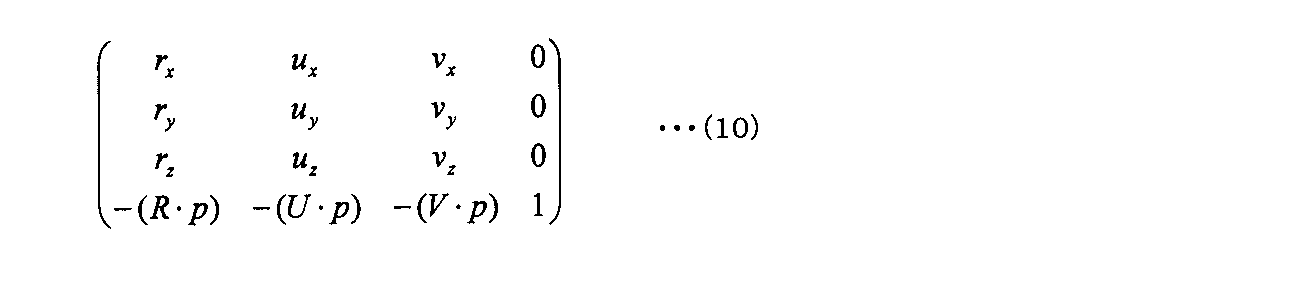
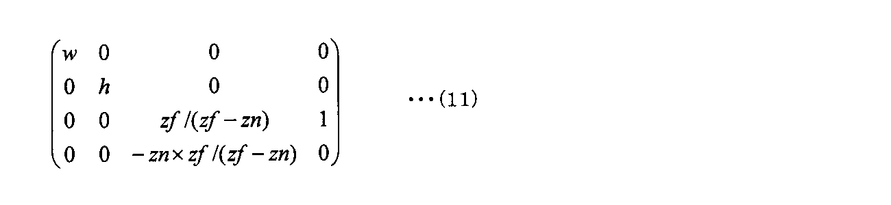
続いて、ビュー変換されたシーンに対して遠くのものが小さく、近くのものが大きく見えるように透視投影処理が実施される。透視投影処理では、撮像装置に近いところ(前方投影面)と、遠いところ(後方投影面)に対して2つの投影面が導入され、撮像装置原点を中心とした錘状になるように設定される。プロジェクション変換によって、近いところの面と遠いところの面の間の空間が立方体になるように変換することによって、近いところが大きく、遠いところが小さく見えるような変換がなされる。このプロジェクション変換によって、射影座標系に変換される。水平方向の視野角をw、垂直方向の視野角をhとし、仮想撮像装置の位置から前方投影面までの距離をzn、後方投影面までの距離をzfとすると、以下の行列によって射影座標系に変換することができる。
さらに、表示装置に表示するために、射影座標系からスクリーン座標系への変換が行なわれる。スクリーン座標系では、表示装置の左上を原点に、またY軸の向きが逆になるような変換が行なわれる。表示装置の水平方向の画素数をWidth、垂直方向の画素数をHeightとすると変換行列は、以下のようになる。
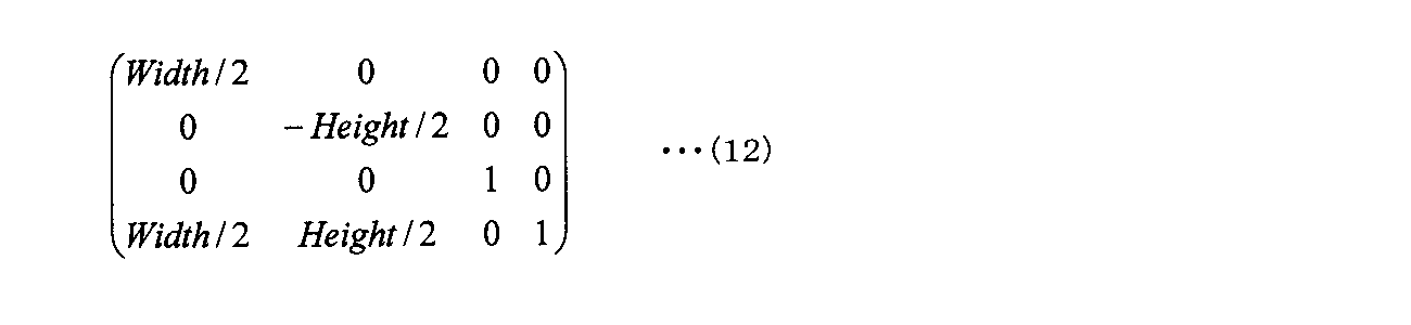
以上3DCGレンダリング技術により利用者の位置から見た画像が生成される。
続いて、本発明に関わる、遠隔地に居る利用者が隣にいるような位置関係で、共通の作業オブジェクトを見ながらコミュニケーションを行うための視点制御方法について、図5~図9を用いて説明する。
図5は、本システムを一般的な対面のテレビ会議システムのように利用した場合に、システム全体を上部から見下ろした図(上面図)である。図の500及び501は、図1に示した1~5の構成を含む映像提示システムである。500は、図1で示した利用者9側の映像提示システムで、501は遠隔地に設置してある映像提示システムである。利用者は9と7で、7は遠隔地に居る利用者である。
図5は、本システムを一般的な対面のテレビ会議システムのように利用した場合に、システム全体を上部から見下ろした図(上面図)である。図の500及び501は、図1に示した1~5の構成を含む映像提示システムである。500は、図1で示した利用者9側の映像提示システムで、501は遠隔地に設置してある映像提示システムである。利用者は9と7で、7は遠隔地に居る利用者である。
システム間は、ネットワーク6等を介して接続され、お互いが通信できるようなっている。504及び505は、それぞれ利用者9の側のシステムのワールド座標系Xworld_Aと利用者7の側のシステムのワールド座標系Xworld_Bを示している。ワールド座標系Xworld_Aは、ディスプレイ面に向かって右の方向にx軸の正の方向、ディスプレイ面の奥に向かってz軸の正の方向となり、また図示していないy軸の正の方向は上方向に向かっているものとする。
同様に、ワールド座標系Xworld_Bは、利用者7がディスプレイに向かっている方向を基準として、ディスプレイの右方向(図面では左方向)をx軸の正の方向、ディスプレイ面の奥の方向(図面では下方向)をz軸の正の方向とし、また図示していないy軸の正の方向は上方向に向かっているものとする。
続いて、本発明に関わる作業の形態(利用者と電子データの位置関係)を図示したものが図6である。利用者9と利用者7が隣に居て、お互いに作業物600(電子データを明示的に示したもの)を見ることができる位置関係を模式的に示している。
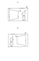
図7は、図6の位置関係を実現した場合に、表示装置に映る遠隔地の映像を模式的に示した図である。図7(A)は利用者9が見る映像で、図7(B)は利用者7が見る映像である。
図7は、図6の位置関係を実現した場合に、表示装置に映る遠隔地の映像を模式的に示した図である。図7(A)は利用者9が見る映像で、図7(B)は利用者7が見る映像である。
図6に示したように、利用者9にとって、作業物600は左側で利用者7は右側に位置する。従って、利用者9が見る遠隔地の映像506は、作業物600は左に見え、利用者7の映像700は右側に見える。一方、利用者7にとって、作業物600は右側で、利用者9は左側に位置する。従って、利用者7が見る遠隔地の映像507は、作業物600は右に見え、利用者9の映像701は左側に見える。
以上、図7に示した映像を提示することによって、利用者は図6に示したような位置関係で、遠隔地間で共通の電子データと相手の映像を見ながらコミュニケーションを行うことができる。
以上、図7に示した映像を提示することによって、利用者は図6に示したような位置関係で、遠隔地間で共通の電子データと相手の映像を見ながらコミュニケーションを行うことができる。
具体的に、上記図7に示したような視点の映像を生成する方法について、図8を用いて説明する。初めに、利用者の位置関係を明確にしておく必要がある。これは、利用者は2地点に居て、図6あるいは図7に示したように、利用者9であるか、利用者7であるかによって、提示される映像内の相手の映像と電子データの表示位置が異なるためである。
利用者の位置関係を確定させる方法として、例えば、予め双方の位置(図6におけるどちらの利用者であるか)を決めておく方法がある。利用者は、映像・音声処理装置100に接続された操作装置5を使って、図9に示すユーザ表示に従い、お互いの位置を設定することができる。設定結果は、映像・音声処理装置100の内部にあるCPU208に保持される。CPU208は、図示していない通信手段を用いて、遠隔地にある映像提示システムと連携して、図9に示す設定値が排他的(一方が選択した項目は、相手側では選択できない)になるように制御しても良い。以上の方法により、双方の位置が明確になる。
続いて、映像の取得方法について説明する。図8において、利用者7の側のシステム501に表示する遠隔地の映像は、利用者9の側の映像である。その映像の取得方法は、利用者9及びシステム500の側に、図6に示すような位置関係になるように利用者7が存在していると仮定して、その利用者7の位置にカメラを設置して取得する。つまり、実際には存在していない遠隔地の利用者が仮に隣に居たとして、そこから撮影した映像を相手側に伝送することで実現できる。そのためには、お互いの利用者位置をもう一方のシステムにおける仮想的な位置に変換する処理、すなわち、一方のシステムの座標系をもう一方のシステムの座標系に変換することが必要である。この変換によって、もう一方のシステムの座標系における位置を同じ座標系として扱うことが可能で、例えば、利用者9の側のシステムにおける、利用者7の仮想的な位置、すなわち、利用者7の側のシステムに送る映像を取得するカメラ設置位置を算出することが可能になる。しかしながら、システム500とシステム501は物理的に接合しておらず、双方の座標系を関連付けることができない(座標系を変換する基準となる物理的な位置関係が不明確である)。本発明では、共通に利用する電子データ600を座標系変換の基準とすることで、双方の座標系を関連付けて、座標系変換を実現する。利用者9の側のシステム500に表示する遠隔地の映像の取得方法も同様である。
CPU208は、映像提示システムに設定されたワールド座標系(図8の500のシステムの場合Xworld_A(504)、501のシステムの場合Xworld_B(505))内に配置された電子データの基本情報のうち、各ワールド座標系における位置(500のシステムの場合805、501のシステムの場合806)とその方向ベクトル(500のシステムの場合807、501のシステムの場合808)を用いて、以下の方法によって遠隔地システムのための映像を取得するカメラ設置位置を決める。
CPU208は、遠隔地のシステムのワールド座標系Xworld_Bを、電子データの座標系を経由して、利用するシステムの座標系Xworld_Aに変換する。ここで、システム500の座標系Xworld_Aにおける電子データ中心の3次元位置805をPE_A、方向ベクトル807を→HE_Aとし、システム501の座標系Xworld_Bにおける電子データ中心の3次元位置806をPE_B、方向ベクトル808を→HE_Bとする。CPU208は、式(7)を用いて、システム501の座標系Xworld_Bを、一旦システム501における電子データの座標系に変換する。式(7)に適用する、回転マトリクスRW_BE_Bと併進マトリクスTW_BE_Bは以下の様に求める。
回転マトリクスRW_BE_Bは、システム501の座標系Xworld_Bから電子データ600の座標系への回転であり、システム501の表示装置の向いている方向から電子データ600の向いている方向への回転と同じである。ここで、システム501の表示装置の向き803を→HD_B(座標系Xworld_Bを用いると→HD_B=(0,0,-1)である)、電子データ600の向きを→HE_Bとすると、→HD_Bと→HE_B間において、内積の公式を展開してX軸周り、Y軸周り、Z軸周りの回転角度(θx_DE_B,θy_DE_B,θz_DE_B)を求める。以上の回転角度を、式(8)に代入して回転マトリクスRW_BE_Bを算出する。
併進マトリクスTW_BE_Bは、システム501の座標系Xworld_Bの原点OW_Bから電子データ600の中心位置PE_Bに向かうベクトルから構成され、以下の式のとおりである。
併進マトリクスTW_BE_Bは、システム501の座標系Xworld_Bの原点OW_Bから電子データ600の中心位置PE_Bに向かうベクトルから構成され、以下の式のとおりである。

続いて、CPU208は、システム500において、上記方法と同様に電子データの座標系からワールド座標系Xworld_Aに変換するための回転マトリクスRE_AW_Aと併進マトリクスTE_AW_Aを求める。
CPU208は、以下の式を用いて、遠隔地のシステム501の座標系を利用するシステム500の座標系に変換する。
CPU208は、以下の式を用いて、遠隔地のシステム501の座標系を利用するシステム500の座標系に変換する。

この変換式によって、CPU208は、遠隔地のシステム501におけるワールド座標系Xworld_B内の座標を、利用するシステム500の座標系Xworld_Aにおける座標に変換することができる。
CPU208は、遠隔地の利用者7の位置を式(14)に従って変換し、変換された座標位置に遠隔地システムのための映像を取得するカメラを設置する。CPU208は、そのカメラによって取得した映像を、遠隔地のシステム501に伝送する。
利用者9及び利用者7の位置は、適正視距離、例えば3H(ディスプレイ面の垂直の長さの3倍)によって、設定可能である。あるいは、例えば利用者の位置をトラッキングする装置を装着して、利用者位置をリアルタイムに算出しても良い。
CPU208は、遠隔地の利用者7の位置を式(14)に従って変換し、変換された座標位置に遠隔地システムのための映像を取得するカメラを設置する。CPU208は、そのカメラによって取得した映像を、遠隔地のシステム501に伝送する。
利用者9及び利用者7の位置は、適正視距離、例えば3H(ディスプレイ面の垂直の長さの3倍)によって、設定可能である。あるいは、例えば利用者の位置をトラッキングする装置を装着して、利用者位置をリアルタイムに算出しても良い。
以上により、利用者が3次元的な位置に関する設定を行うことなく、簡易な手法で、遠隔地の人が隣に居るような位置関係で共通の電子データを見ることができる視点の映像を取得することができる。双方にこの映像を伝送し合うことで、上記位置関係でコミュニケーションをすることができる。なお、上記視点の制御は、システム開始時に一度設定するだけにしても良いし、随時設定を変えるような仕組みにしても良い。なお、仮想カメラの撮影画角については、上記システムが既知、つまり表示装置の大きさが限定できる場合は、設定を変える必要はない。また、システムごとに表示装置の大きさが変わる場合には、相手の表示装置に応じて撮影画角を変えるような仕組みを設けても良い。
<フローチャート>
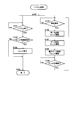
次に、本実施形態に係る映像・音声処理装置(映像処理)100が行う処理について説明する。図10~図14は、本実施形態に係る映像・音声処理装置(映像処理)100が行う処理を示すフローチャートである。なお、以下のフローチャート及び、その説明において、音声信号の処理は必要なところのみ記述する。
映像・音声処理装置(映像処理)100は、図示していないシステム全体を制御する制御部によって、システム処理を開始すると、ステップS100に進む。
次に、本実施形態に係る映像・音声処理装置(映像処理)100が行う処理について説明する。図10~図14は、本実施形態に係る映像・音声処理装置(映像処理)100が行う処理を示すフローチャートである。なお、以下のフローチャート及び、その説明において、音声信号の処理は必要なところのみ記述する。
映像・音声処理装置(映像処理)100は、図示していないシステム全体を制御する制御部によって、システム処理を開始すると、ステップS100に進む。
(ステップS100)映像・音声処理装置(映像処理)100は、前記制御部によって、システム全体の稼働を監視するための処理(図10の左側の処理、S101~S104)と通信を行うための処理(図10の右側の処理、S105~S109)を同時に開始させる。双方の処理を開始させると、ステップS101とS105に進む。
始めに、システム全体の稼働を監視するための処理について説明する。
(ステップS101)映像・音声処理装置(映像処理)100は、前記制御部によって、システムが終了したか否かを常に監視し、終了していない場合はステップS101の処理を繰り返す。終了した場合には、ステップS102に進む。
(ステップS102)映像・音声処理装置(映像処理)100は、前記制御部によって、前記通信を行うための処理において実行するスレッドの状態を監視し、スレッドが実行中である場合はステップS103に進み、スレッドが全て完了している場合はステップS104に進む。
(ステップS101)映像・音声処理装置(映像処理)100は、前記制御部によって、システムが終了したか否かを常に監視し、終了していない場合はステップS101の処理を繰り返す。終了した場合には、ステップS102に進む。
(ステップS102)映像・音声処理装置(映像処理)100は、前記制御部によって、前記通信を行うための処理において実行するスレッドの状態を監視し、スレッドが実行中である場合はステップS103に進み、スレッドが全て完了している場合はステップS104に進む。
(ステップS103)映像・音声処理装置(映像処理)100は、前記制御部によって、前記通信を行うための処理において実行しているスレッドを強制的に終了させ、ステップS104に進む。
(ステップS104)映像・音声処理装置(映像処理)100は、前記制御部によって、全ての処理が停止していることを確認して、システムを終了させる。
続いて、通信を行うための処理について説明する。
(ステップS104)映像・音声処理装置(映像処理)100は、前記制御部によって、全ての処理が停止していることを確認して、システムを終了させる。
続いて、通信を行うための処理について説明する。
(ステップS105)映像・音声処理装置(映像処理)100は、前記制御部によって、常に遠隔地との間で通信を開始できる状態にあるかを監視し、通信を開始できる状態であればステップS106に進み、通信を開始できる状態でない場合はステップS105の処理を繰り返す。
(ステップS106)映像・音声処理装置(映像処理)100は、前記制御部によって、後述するデータ送信スレッドを開始させ、ステップS107に進む。
(ステップS107)映像・音声処理装置(映像処理)100は、前記制御部によって、後述するデータ受信スレッドを開始させ、ステップS108に進む。
(ステップS106)映像・音声処理装置(映像処理)100は、前記制御部によって、後述するデータ送信スレッドを開始させ、ステップS107に進む。
(ステップS107)映像・音声処理装置(映像処理)100は、前記制御部によって、後述するデータ受信スレッドを開始させ、ステップS108に進む。
(ステップS108)映像・音声処理装置(映像処理)100は、前記制御部によって、後述する電子データ制御スレッドを開始させ、ステップS109に進む。
(ステップS109)映像・音声処理装置(映像処理)100は、前記制御部によって、上記開始させたスレッドの状態を常に監視し、全てのスレッドの処理が完了していることを検知した場合はステップS105に戻り上記処理を繰り返す。一方監視しているスレッドが全て終了していない場合は、ステップS109に戻り処理を繰り返す。
(ステップS109)映像・音声処理装置(映像処理)100は、前記制御部によって、上記開始させたスレッドの状態を常に監視し、全てのスレッドの処理が完了していることを検知した場合はステップS105に戻り上記処理を繰り返す。一方監視しているスレッドが全て終了していない場合は、ステップS109に戻り処理を繰り返す。
次に、データ送信スレッドについて、図11を用いて説明する。データ送信スレッドは、上記システム処理によって起動される。
(ステップS200)映像処理装置(送信側)102は、後述する送信フレーム情報生成処理によって、送信するフレーム情報を生成し、ステップS201に進む。
(ステップS201)映像処理装置(送信側)102の内部にある送信制御部209は、生成された送信フレーム情報を、よりデータ量の少ない符号に圧縮する方法(例えば、国際標準動画圧縮規格H.264等)を用いて符号化(エンコード)し、ステップS202に進む。
(ステップS200)映像処理装置(送信側)102は、後述する送信フレーム情報生成処理によって、送信するフレーム情報を生成し、ステップS201に進む。
(ステップS201)映像処理装置(送信側)102の内部にある送信制御部209は、生成された送信フレーム情報を、よりデータ量の少ない符号に圧縮する方法(例えば、国際標準動画圧縮規格H.264等)を用いて符号化(エンコード)し、ステップS202に進む。
(ステップS202)映像処理装置(送信側)102の内部にある送信制御部209は、図2の音声処理装置(送信側)103と連携して、符号化された映像信号と音声信号をパッキング(packing;詰込)し、ステップS203に進む。
(ステップS203)映像・音声処理装置100は、生成された符号データを、ネットワークを介して、遠隔地の映像提示装置に向けて伝送する。その後、ステップS204に進む。
(ステップS204)映像・音声処理装置100は、前記制御部によって、通信を終了させるか否かを常に監視し、終了させる場合はステップS205に進み、終了させない場合はステップS200に戻り上記処理を繰り返す。
(ステップS205)映像・音声処理装置100は、データ送信スレッドを終了させる。
(ステップS203)映像・音声処理装置100は、生成された符号データを、ネットワークを介して、遠隔地の映像提示装置に向けて伝送する。その後、ステップS204に進む。
(ステップS204)映像・音声処理装置100は、前記制御部によって、通信を終了させるか否かを常に監視し、終了させる場合はステップS205に進み、終了させない場合はステップS200に戻り上記処理を繰り返す。
(ステップS205)映像・音声処理装置100は、データ送信スレッドを終了させる。
次に、ステップS200で実施する送信フレーム情報生成処理について、図12を用いて説明する。
(ステップS300)映像処理装置(送信側)102は、外部入力端子(I/F)200及び201を介して、撮影装置2aと2bで撮影した映像(フレーム)を取り込む。その後、ステップS301に進む。
(ステップS301)映像モデル生成部202は、前記入力されたマルチ画像を基に、映像モデルを生成する。その後、ステップS302に進む。
(ステップS302)電子データモデル生成部205は、後述する電子データ制御スレッドが生成する最新の電子データ属性情報に基づいて電子データのモデル情報を生成する。その後、ステップS303に進む。
(ステップS300)映像処理装置(送信側)102は、外部入力端子(I/F)200及び201を介して、撮影装置2aと2bで撮影した映像(フレーム)を取り込む。その後、ステップS301に進む。
(ステップS301)映像モデル生成部202は、前記入力されたマルチ画像を基に、映像モデルを生成する。その後、ステップS302に進む。
(ステップS302)電子データモデル生成部205は、後述する電子データ制御スレッドが生成する最新の電子データ属性情報に基づいて電子データのモデル情報を生成する。その後、ステップS303に進む。
(ステップS303)映像・データ合成部206は、映像モデル生成部202から入力した映像モデルと電子データモデル生成部205から入力した電子データモデルをワールド座標系内で合成し、ステップS304に進む。
(ステップS304)視点生成部207は、映像・データ合成部206から入力した合成されたモデル情報に基づいて、本発明に関わる前記視点の画像(フレーム)を生成し、ステップS305に進む。
(ステップS305)視点生成部207は、生成したフレームの信号を、送信制御部209に出力して、送信フレーム情報生成処理を終了する。
(ステップS304)視点生成部207は、映像・データ合成部206から入力した合成されたモデル情報に基づいて、本発明に関わる前記視点の画像(フレーム)を生成し、ステップS305に進む。
(ステップS305)視点生成部207は、生成したフレームの信号を、送信制御部209に出力して、送信フレーム情報生成処理を終了する。
次に、データ受信スレッドについて、図13を用いて説明する。データ受信スレッドは、上記システム処理によって起動される。
(ステップS400)映像処理装置105の内部にある受信制御部212は、遠隔地にある映像提示システムから送信された符号化データを、ネットワークを介して受信する。その後、ステップS401に進む。
(ステップS401)映像処理装置104の内部にある受信制御部212は、音声処理装置106の内部にある図示していない受信制御部と連携して、受信した符号化データを映像符号化データと音声符号化データに分割する。その後、ステップS402に進む。
(ステップS400)映像処理装置105の内部にある受信制御部212は、遠隔地にある映像提示システムから送信された符号化データを、ネットワークを介して受信する。その後、ステップS401に進む。
(ステップS401)映像処理装置104の内部にある受信制御部212は、音声処理装置106の内部にある図示していない受信制御部と連携して、受信した符号化データを映像符号化データと音声符号化データに分割する。その後、ステップS402に進む。
(ステップS402)映像処理装置104の内部にある受信制御部212は、映像符号化データに対して、前記圧縮とは逆の処理を行い、データ量の多い元の信号を復元する。その後、ステップS403に進む。
(ステップS403)受信制御部212は、復元した画像信号を、表示メモリ213に書き込む。表示装置1は、表示メモリ213に書き込まれた画像信号を、定期的に読み出し、画面に表示する。その後、ステップS404に進む。
(ステップS403)受信制御部212は、復元した画像信号を、表示メモリ213に書き込む。表示装置1は、表示メモリ213に書き込まれた画像信号を、定期的に読み出し、画面に表示する。その後、ステップS404に進む。
(ステップS404)映像・音声処理装置100は、前記制御部によって、通信を終了させるか否かを常に監視し、終了させる場合はステップS405に進み、終了させない場合はステップS400に戻り上記処理を繰り返す。
(ステップS405)映像・音声処理装置100は、データ受信スレッドを終了させる。
(ステップS405)映像・音声処理装置100は、データ受信スレッドを終了させる。
次に、電子データ制御スレッドについて、図14を用いて説明する。電子データ制御スレッドは、上記システム処理によって起動される。
(ステップS500)映像処理装置(送信側)102内のCPU208は、操作装置5を用いてユーザが設定する電子データの属性(後述)変更を常に監視し、属性が変更された場合はステップS501に進む。属性が変更されない場合は、ステップS500の処理を繰り返す。
(ステップS500)映像処理装置(送信側)102内のCPU208は、操作装置5を用いてユーザが設定する電子データの属性(後述)変更を常に監視し、属性が変更された場合はステップS501に進む。属性が変更されない場合は、ステップS500の処理を繰り返す。
(ステップS501)CPU208は、電子データの属性情報を更新し、電子データモデル生成部205に最新の属性情報を出力し、前記電子データモデル生成処理にその内容を反映させる。その後、ステップS502に進む。
(ステップS502)CPU208は、更新された電子データ属性情報を図示しないネットワークを介した別の手段によって、遠隔地の映像提示装置にその属性情報を伝送する。その後、ステップS503に進む。
(ステップS502)CPU208は、更新された電子データ属性情報を図示しないネットワークを介した別の手段によって、遠隔地の映像提示装置にその属性情報を伝送する。その後、ステップS503に進む。
(ステップS503)映像・音声処理装置100は、前記制御部によって、通信を終了させるか否かを常に監視し、終了させる場合はステップS504に進み、終了させない場合はステップS500に戻り上記処理を繰り返す。
(ステップS504)映像・音声処理装置100は、電子データ制御スレッドを終了させる。
(ステップS504)映像・音声処理装置100は、電子データ制御スレッドを終了させる。
<送信するデータ>
図14のステップS501において生成する電子データ属性情報について、図15を用いて説明する。電子データ属性情報は、例えば電子データの3次元位置と面の向きと大きさを示す情報で、電子データを上記ワールド座標系内の3次元位置に配置させることが可能な情報である。
図12の送信フレーム情報生成処理で生成する送信フレーム情報について、図16を用いて説明する。送信フレーム情報は、例えば画素数(横方向):widthと画素数(縦方向):heightと画素情報から構成された、1枚分の画像を表す情報である。
図14のステップS501において生成する電子データ属性情報について、図15を用いて説明する。電子データ属性情報は、例えば電子データの3次元位置と面の向きと大きさを示す情報で、電子データを上記ワールド座標系内の3次元位置に配置させることが可能な情報である。
図12の送信フレーム情報生成処理で生成する送信フレーム情報について、図16を用いて説明する。送信フレーム情報は、例えば画素数(横方向):widthと画素数(縦方向):heightと画素情報から構成された、1枚分の画像を表す情報である。
(実施形態2)
<ソフトウェア>
上述した実施形態における映像・音声処理装置100の一部、例えば、映像モデル生成部202、電子データモデル生成部205、映像・データ合成部206、視点生成部207、送信制御部209、並びに受信制御部212をコンピュータで実現するようにしても良い。その場合、この制御機能を実現するためのプログラムをコンピュータ読み取り可能な記録媒体に記録して、この記録媒体に記録されたプログラムをコンピュータシステムに読み込ませ、実行することによって実現しても良い。なお、ここでいう「コンピュータシステム」とは、映像・音声処理装置に内蔵されたコンピュータシステム及びDSP(デジタル・シグナル・プロセッサ)であって、OSや周辺機器等のハードウェアを含むものとする。
<ソフトウェア>
上述した実施形態における映像・音声処理装置100の一部、例えば、映像モデル生成部202、電子データモデル生成部205、映像・データ合成部206、視点生成部207、送信制御部209、並びに受信制御部212をコンピュータで実現するようにしても良い。その場合、この制御機能を実現するためのプログラムをコンピュータ読み取り可能な記録媒体に記録して、この記録媒体に記録されたプログラムをコンピュータシステムに読み込ませ、実行することによって実現しても良い。なお、ここでいう「コンピュータシステム」とは、映像・音声処理装置に内蔵されたコンピュータシステム及びDSP(デジタル・シグナル・プロセッサ)であって、OSや周辺機器等のハードウェアを含むものとする。
また、「コンピュータ読み取り可能な記録媒体」とは、フレキシブルディスク、光磁気ディスク、ROM、CD-ROM等の可搬媒体、コンピュータシステムに内蔵されるハードディスク等の記憶装置のことをいう。さらに「コンピュータ読み取り可能な記録媒体」とは、インターネット等のネットワークや電話回線等の通信回線を介してプログラムを送信する場合の通信線のように、短時間、動的にプログラムを保持するもの、その場合のサーバやクライアントとなるコンピュータシステム内部の揮発性メモリのように、一定時間プログラムを保持しているものも含んでも良い。また上記プログラムは、前述した機能の一部を実現するためのものであっても良く、さらに前述した機能をコンピュータシステムにすでに記録されているプログラムとの組み合わせで実現できるものであっても良い。
また、上述した実施形態における映像・音声処理装置100の一部、または全部を、LSI(Large Scale Integration)等の集積回路として実現しても良い。映像・音声処理装置100の各機能ブロックは個別にプロセッサ化してもよいし、一部、または全部を集積してプロセッサ化しても良い。また、集積回路化の手法はLSIに限らず専用回路、または汎用プロセッサで実現しても良い。また、半導体技術の進歩によりLSIに代替する集積回路化の技術が出現した場合、当該技術による集積回路を用いても良い。
1…表示装置、2…マルチメディア情報取得装置、2a…撮影装置、2b…撮影装置、3…音声再生装置、4…計算機、5…操作装置、6…ネットワーク、7…利用者、8…電子データ、9…利用者、10…マルチメディア情報提示装置、11…マルチメディア情報取得装置、12…マルチメディア情報提示装置、100…映像・音声処理装置、101…送信装置、102…映像処理装置、103…音声処理装置、104…受信装置、106…音声処理装置、107…映像・音声処理装置、108…送信装置、109…受信装置、202…映像モデル生成部、203…外部サーバ、205…電子データモデル生成部、206…映像・データ合成部、207…視点生成部、208…CPU、209…送信制御部、212…受信制御部、213…表示メモリ、500…システム、501…システム、506…映像、507…映像、600…作業物、700…映像、701…映像。
Claims (8)
- 撮影装置によって取得された撮影映像を入力し、該入力した撮影映像に、画像として生成された電子データを加工して合成し、該合成した映像を送受信することにより、遠隔地間でコミュニケーションを行なうことを可能とした映像提示システムであって、
撮影する範囲の奥行き情報と、該奥行き情報を基に該奥行き情報に貼り付けた映像情報とからなる映像モデルを生成する映像モデル生成部と、
電子データを入力し、該入力した電子データの位置、大きさ、向きの情報を含む基準情報に基づいて電子データモデルを生成する電子データモデル生成部と、
共通の座標系を設けて、前記映像モデルと前記電子データモデルを共通の座標系内で合成する映像・データ合成部と、
該映像・データ合成部で合成されたモデルを入力し、前記共通の座標空間に仮想的な視点を設置して、該視点の映像を生成する視点生成部と、
該視点生成部で取得した映像を送信する送信部と、を有することを特徴とする映像提示システム。 - 前記視点生成部は、前記電子データの3次元的な位置と前記共通の座標系における利用者の相対的な位置関係に基づいて算出された視点位置の映像を生成することを特徴とする請求項1に記載の映像提示システム。
- 利用者による操作入力を受け付ける操作装置と、
前記電子データの位置及び利用者の視点位置を設定するための表示画面を表示装置に表示させる制御手段とを有し、前記視点生成部は、前記表示画面に対する前記操作装置の操作入力に従って、前記電子データの3次元的な位置及び利用者の視点位置を決定することを特徴とする請求項2に記載の映像提示システム。 - 利用者の3次元上の位置を計測する3次元位置計測装置を有し、
前記視点生成部は、前記3次元位置計測装置による計測結果に従って、利用者の位置をリアルタイムに変更することを特徴とする請求項1~3のいずれか1に記載の映像提示システム。 - 前記撮影装置を複数備え、
前記映像モデル生成部は、複数の前記撮影装置で撮影された映像から視差画像を生成し、該生成した視差画像に基づいて撮影された対象のデプスを示すデプスマップを生成し、該デプスマップから前記撮影装置の固有の座標系における奥行き情報を生成し、該撮影装置の固有の座標系を前記映像提示システムで扱う共通座標系に変換して、奥行き情報と該奥行き情報に貼り付けた映像情報とからなる前記映像モデルを生成することを特徴とする、請求項1~4のいずれか1に記載の映像提示システム。 - 撮影装置によって取得された撮影映像を入力し、該入力した撮影映像に、画像として生成された電子データを加工して合成し、該合成した映像を送受信することにより、遠隔地間でコミュニケーションを行なうことを可能とした映像提示方法であって、
撮影する範囲の奥行き情報と、該奥行き情報を基に該奥行き情報に貼り付けた映像情報とからなる映像モデルを生成する第1の過程と、
電子データを入力し、該入力した電子データの位置、大きさ、向きの情報を含む基準情報に基づいて該電子データモデルを生成する第2の過程と、
共通の座標系を設けて、前記映像モデルと前記電子データモデルを共通の座標系内で合成する第3の過程と、
該第3の過程で合成されたモデルを入力し、前記共通の座標空間に仮想的な視点を設置して、該視点の映像を生成する第4の過程と、
該第4の過程で取得した映像を送信する第5の過程と、を有することを特徴とする映像提示方法。 - 撮影装置によって取得された撮影映像を入力し、該入力した撮影映像に、画像として生成された電子データを加工して合成し、該合成した映像を送受信することにより、遠隔地間でコミュニケーションを行なうことを可能とした映像提示装置のコンピュータに、
撮影する範囲の奥行き情報と、該奥行き情報を基に該奥行き情報に貼り付けた映像情報とからなる映像モデルを生成する手順と、
電子データを入力し、該入力した電子データの位置、大きさ、向きの情報を含む基準情報に基づいて該電子データモデルを生成する手順と、
共通の座標系を設けて、前記映像モデルと前記電子データモデルを共通の座標系内で合成する手順と、
該合成されたモデルを入力し、前記共通の座標空間に仮想的な視点を設置して、該視点の映像を生成する手順と、
該生成された映像を送信する手順を実行させるための映像提示プログラム。 - 請求項7に記載の映像提示プログラムを、コンピュータ読み取り可能に記録した記録媒体。
Applications Claiming Priority (2)
| Application Number | Priority Date | Filing Date | Title |
|---|---|---|---|
| JP2011-110160 | 2011-05-17 | ||
| JP2011110160A JP5200141B2 (ja) | 2011-05-17 | 2011-05-17 | 映像提示システム、映像提示方法、プログラム及び記録媒体 |
Publications (1)
| Publication Number | Publication Date |
|---|---|
| WO2012157516A1 true WO2012157516A1 (ja) | 2012-11-22 |
Family
ID=47176844
Family Applications (1)
| Application Number | Title | Priority Date | Filing Date |
|---|---|---|---|
| PCT/JP2012/061996 Ceased WO2012157516A1 (ja) | 2011-05-17 | 2012-05-10 | 映像提示システム、映像提示方法、プログラム及び記録媒体 |
Country Status (2)
| Country | Link |
|---|---|
| JP (1) | JP5200141B2 (ja) |
| WO (1) | WO2012157516A1 (ja) |
Cited By (1)
| Publication number | Priority date | Publication date | Assignee | Title |
|---|---|---|---|---|
| CN115062183A (zh) * | 2015-06-19 | 2022-09-16 | 连株式会社 | 服务器的控制方法、计算机可读记录介质及系统 |
Families Citing this family (1)
| Publication number | Priority date | Publication date | Assignee | Title |
|---|---|---|---|---|
| KR101748637B1 (ko) | 2014-08-05 | 2017-06-20 | 한국전자통신연구원 | 깊이 맵 생성 장치 및 방법 |
Citations (5)
| Publication number | Priority date | Publication date | Assignee | Title |
|---|---|---|---|---|
| JPH08153213A (ja) * | 1994-09-29 | 1996-06-11 | Hitachi Ltd | 画像合成表示方法 |
| JP2004178036A (ja) * | 2002-11-25 | 2004-06-24 | Hitachi Ltd | 遠隔者の映像を伴う仮想空間の提示装置 |
| JP2005049996A (ja) * | 2003-07-30 | 2005-02-24 | Canon Inc | 画像表示方法及び装置 |
| JP2006293604A (ja) * | 2005-04-08 | 2006-10-26 | Canon Inc | 情報処理方法、情報処理装置および遠隔複合現実感共有装置 |
| JP2010217719A (ja) * | 2009-03-18 | 2010-09-30 | Ricoh Co Ltd | 装着型表示装置、その制御方法及びプログラム |
Family Cites Families (1)
| Publication number | Priority date | Publication date | Assignee | Title |
|---|---|---|---|---|
| JP4677269B2 (ja) * | 2005-04-08 | 2011-04-27 | キヤノン株式会社 | 情報処理方法およびシステム |
-
2011
- 2011-05-17 JP JP2011110160A patent/JP5200141B2/ja not_active Expired - Fee Related
-
2012
- 2012-05-10 WO PCT/JP2012/061996 patent/WO2012157516A1/ja not_active Ceased
Patent Citations (5)
| Publication number | Priority date | Publication date | Assignee | Title |
|---|---|---|---|---|
| JPH08153213A (ja) * | 1994-09-29 | 1996-06-11 | Hitachi Ltd | 画像合成表示方法 |
| JP2004178036A (ja) * | 2002-11-25 | 2004-06-24 | Hitachi Ltd | 遠隔者の映像を伴う仮想空間の提示装置 |
| JP2005049996A (ja) * | 2003-07-30 | 2005-02-24 | Canon Inc | 画像表示方法及び装置 |
| JP2006293604A (ja) * | 2005-04-08 | 2006-10-26 | Canon Inc | 情報処理方法、情報処理装置および遠隔複合現実感共有装置 |
| JP2010217719A (ja) * | 2009-03-18 | 2010-09-30 | Ricoh Co Ltd | 装着型表示装置、その制御方法及びプログラム |
Non-Patent Citations (1)
| Title |
|---|
| KO SUZUKI ET AL.: "Development of Auto-stereoscopic Display System for Remote Manipulation : The Addition of Motion Parallax to Display Stereoscopic Images", ITE TECHNICAL REPORT, vol. 30, no. 52, 18 October 2006 (2006-10-18), pages 13 - 16 * |
Cited By (1)
| Publication number | Priority date | Publication date | Assignee | Title |
|---|---|---|---|---|
| CN115062183A (zh) * | 2015-06-19 | 2022-09-16 | 连株式会社 | 服务器的控制方法、计算机可读记录介质及系统 |
Also Published As
| Publication number | Publication date |
|---|---|
| JP2012242930A (ja) | 2012-12-10 |
| JP5200141B2 (ja) | 2013-05-15 |
Similar Documents
| Publication | Publication Date | Title |
|---|---|---|
| EP2328125B1 (en) | Image splicing method and device | |
| US20210209855A1 (en) | Adapting Acoustic Rendering to Image-Based Object | |
| US20120105581A1 (en) | 2d to 3d image and video conversion using gps and dsm | |
| CN107636534A (zh) | 一般球面捕获方法 | |
| JP7666018B2 (ja) | 画像処理方法、プログラム、画像処理装置および画像処理システム | |
| CN106296589B (zh) | 全景图像的处理方法及装置 | |
| Thatte et al. | Depth augmented stereo panorama for cinematic virtual reality with head-motion parallax | |
| CN101189643A (zh) | 3d图像生成和显示系统 | |
| WO2017128887A1 (zh) | 全景图像的校正3d显示方法和系统及装置 | |
| JP4406824B2 (ja) | 画像表示装置、画素データ取得方法、およびその方法を実行させるためのプログラム | |
| WO2020184174A1 (ja) | 画像処理装置および画像処理方法 | |
| WO2020166376A1 (ja) | 画像処理装置、画像処理方法、及び、プログラム | |
| JP2018033107A (ja) | 動画の配信装置及び配信方法 | |
| JP6091850B2 (ja) | テレコミュニケーション装置及びテレコミュニケーション方法 | |
| CN116018619A (zh) | 信息处理装置、信息处理方法和程序 | |
| TW201824178A (zh) | 全景即時影像處理方法 | |
| US9942540B2 (en) | Method and a device for creating images | |
| CN115222793A (zh) | 深度图像的生成及显示方法、装置、系统、可读介质 | |
| JP5200141B2 (ja) | 映像提示システム、映像提示方法、プログラム及び記録媒体 | |
| KR20250113969A (ko) | 이미지를 디스플레이하고 캡처하기 위한 기법 | |
| CN115761190A (zh) | 基于场景映射的多用户增强现实相片浏览方法及系统 | |
| JP5647813B2 (ja) | 映像提示システム、プログラム及び記録媒体 | |
| Wegner et al. | Omnidirectional view synthesis and test images | |
| JP7336871B2 (ja) | 全天周映像処理装置及びプログラム | |
| CN118898667A (zh) | 图像渲染方法和装置 |
Legal Events
| Date | Code | Title | Description |
|---|---|---|---|
| 121 | Ep: the epo has been informed by wipo that ep was designated in this application |
Ref document number: 12786055 Country of ref document: EP Kind code of ref document: A1 |
|
| NENP | Non-entry into the national phase |
Ref country code: DE |
|
| 122 | Ep: pct application non-entry in european phase |
Ref document number: 12786055 Country of ref document: EP Kind code of ref document: A1 |