WO2012157499A1 - 移動通信方法及び無線基地局 - Google Patents
移動通信方法及び無線基地局 Download PDFInfo
- Publication number
- WO2012157499A1 WO2012157499A1 PCT/JP2012/061941 JP2012061941W WO2012157499A1 WO 2012157499 A1 WO2012157499 A1 WO 2012157499A1 JP 2012061941 W JP2012061941 W JP 2012061941W WO 2012157499 A1 WO2012157499 A1 WO 2012157499A1
- Authority
- WO
- WIPO (PCT)
- Prior art keywords
- mobile station
- interface
- transmission
- base station
- radio base
- Prior art date
Links
Images


Classifications
-
- H—ELECTRICITY
- H04—ELECTRIC COMMUNICATION TECHNIQUE
- H04L—TRANSMISSION OF DIGITAL INFORMATION, e.g. TELEGRAPHIC COMMUNICATION
- H04L5/00—Arrangements affording multiple use of the transmission path
- H04L5/003—Arrangements for allocating sub-channels of the transmission path
- H04L5/0037—Inter-user or inter-terminal allocation
-
- H—ELECTRICITY
- H04—ELECTRIC COMMUNICATION TECHNIQUE
- H04W—WIRELESS COMMUNICATION NETWORKS
- H04W72/00—Local resource management
- H04W72/20—Control channels or signalling for resource management
Definitions
- the present invention relates to a mobile communication method and a radio base station.
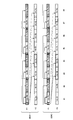
- FIG. 7 shows transmission / reception timing in a conventional LTE (Long Term Evolution) Uu interface (wireless base station interface).
- LTE Long Term Evolution
- Uu interface wireless base station interface
- the mobile station UE receives a control signal via the PDCCH (Physical Downlink Control Channel, physical downlink control channel) at the frequency F1, and the PDSCH (Physical Downlink Shared Channel, physical downlink shared channel). ) To receive the data signal.
- PDCCH Physical Downlink Control Channel, physical downlink control channel
- PDSCH Physical Downlink Shared Channel, physical downlink shared channel
- the mobile station UE is configured to transmit a data signal via PUSCH (Physical Uplink Shared Channel, physical uplink shared channel) at the frequency F2.
- PUSCH Physical Uplink Shared Channel, physical uplink shared channel
- the radio base station eNB uses the “DL resource allocation” for notifying that an opportunity (Uu DL) for receiving a data signal via the Uu interface (PDSCH) is assigned via the PDCCH, or the Uu interface ( It is configured to transmit “UL grant” notifying that an opportunity (Uu UL) for transmitting a data signal via PUSCH) has been allocated.
- the subframe to which “Uu UL” is assigned is determined in consideration of the processing delay from when “UL grant” is received via the PDCCH in the mobile station UE until the data signal (transport block) is created. Is done.
- “Uu UL” is configured to be assigned to a subframe that is X subframes after the subframe to which the PDCCH is assigned.
- the mobile station UE # 1 and the mobile station UE # 2 which are in the “RRC_Connected state” in the cell under the same radio base station eNB will be the radio base station eNB via the Uu interface described above.
- transmission / reception of data signals and control signals between the mobile station UE # 1 and mobile station UE # 2 transmission / reception of data signals via a Ud interface (inter-mobile station interface) set directly between the mobile station UE # 1 and the mobile station UE # 2 May be able to do.
- the mobile station UE # 1 and the mobile station UE # 2 simultaneously perform transmission / reception of the data signal and control signal via the Uu interface and transmission / reception of the data signal via the Ud interface using the same frequency. In other words, the transmission / reception timing must be adjusted.
- An object of the present invention is to provide a mobile communication method and a radio base station.
- the first feature of the present invention is that data signals and control signals are transmitted and received between the first mobile station and the second mobile station and the radio base station via a radio base station interface, and the first mobile station and the radio base station A mobile communication method for transmitting / receiving data signals to / from a second mobile station via an interface between mobile stations, wherein the radio base station is common to the first mobile station and the second mobile station A step A for notifying that an opportunity to perform transmission / reception of a data signal via the inter-mobile station interface is assigned via a physical downlink control channel using identification information; and And a step B of transmitting transmission direction information for notifying the station and the second mobile station of the direction in which the data signal should be transmitted at the opportunity.
- a second feature of the present invention is that data signals and control signals are transmitted and received between the first mobile station and the second mobile station and the radio base station via a radio base station interface, and the first mobile station and the radio base station A radio base station used in a mobile communication system configured to be able to transmit / receive data signals to / from a second mobile station via an interface between mobile stations, wherein the first mobile station and the first mobile station The second mobile station is configured to notify that an opportunity to perform transmission / reception of a data signal via the inter-mobile station interface is allocated via a physical downlink control channel using common identification information.
- the transmission unit transmits transmission direction information for notifying the first mobile station and the second mobile station of the direction in which the data signal should be transmitted at the opportunity. And gist that it is configured to.
- FIG. 1 is an overall configuration diagram of a mobile communication system according to a first embodiment of the present invention.
- FIG. 2 is a functional block diagram of the radio base station according to the first embodiment of the present invention.
- FIG. 3 is a diagram showing transmission / reception timings in the mobile communication system according to the first embodiment of the present invention.
- FIG. 4 is a diagram showing transmission / reception timings in the mobile communication system according to the first embodiment of the present invention.
- FIG. 5 is a diagram showing transmission / reception timings in the mobile communication system according to the first embodiment of the present invention.
- FIG. 6 is a diagram showing transmission / reception timings in the mobile communication system according to the first embodiment of the present invention.
- FIG. 7 is a diagram for explaining a conventional mobile communication system.
- the mobile communication system according to the present embodiment is an LTE mobile communication system, and includes a core network (not shown) and a radio base station eNB connected to the core network as shown in FIG. is doing. Note that the present invention is also applicable to cellular mobile communication systems other than the LTE system.
- the mobile station UE # 1 transmits / receives a data signal and a control signal to / from the radio base station eNB via the Uu interface, and the Ud interface to the mobile station UE # 2. It is configured to transmit and receive data signals via the.
- the mobile station UE # 2 transmits / receives data signals and control signals to / from the radio base station eNB via the Uu interface, and transmits data to / from the mobile station UE # 1 via the Ud interface. It is configured to transmit and receive signals.
- the radio base station eNB includes an allocation unit 11, a transmission unit 12, and a reception unit 13.
- the assigning unit 11 is configured to assign an opportunity to transmit / receive data signals via the Uu interface and an opportunity to transmit / receive data signals via the Ud interface to the mobile station UE # 1 and the mobile station UE2. ing.
- the transmission unit 12 is configured to transmit a data signal and a control signal to the mobile station UE # 1 and the mobile station UE # 2 via the Uu interface.
- the transmission unit 12 uses PDCCH using identification information (C-RNTI: Cell-Radio Network Temporary Identity) of the mobile station UE # 1 and the mobile station UE # 2 for the mobile station UE # 1 and the mobile station UE2.
- C-RNTI Cell-Radio Network Temporary Identity
- “DL resource allocation” for notifying that an opportunity to receive a data signal via the Uu interface (PDSCH) (Uu DL) is assigned, and data via the Uu interface (PUSCH) It is configured to transmit “UL grant” notifying that an opportunity (Uu UL) for signal transmission has been allocated.
- the transmission unit 12 transmits, to the mobile station UE # 1 and the mobile station UE2, via the PDCCH using the common identification information (hereinafter referred to as X-RNTI) of the mobile station UE # 1 and the mobile station UE # 2. It is configured to notify that an opportunity to transmit a data signal (Ud Tx) via the Ud interface has been allocated and an opportunity to receive a data signal via the Ud interface (Ud Rx) has been allocated. ing.
- X-RNTI common identification information
- the mobile station UE # 1 and the mobile station UE # 2 can use the X-RNTI common to the mobile station UE # 1 and the mobile station UE # 2.
- the amount of signaling related to PDCCH can be suppressed as compared with the case where each C-RNTI of mobile station UE # 2 is used.
- the transmission unit 12 may be configured to allocate such X-RNTI to the mobile station UE # 1 and the mobile station UE # 2 in advance via RRC signaling. Such X-RNTI may be notified when the Ud interface is set.
- the transmission unit 12 is configured to transmit a data signal via the PDSCH to the mobile station UE # 1 and the mobile station UE2 at the opportunity allocated by the allocation unit 11.
- the mobile station UE # 1 and the mobile station UE # 2 perform “blind decode” on the PDCCH transmitted using its own C-RNTI and also perform the “blind decode” on the PDCCH transmitted using the X-RNTI. To “blind decode”.
- the receiving unit 13 is configured to receive a data signal and a control signal from the mobile station UE # 1 and the mobile station UE # 2 via the Uu interface.
- the transmission unit 12 is configured to receive a data signal from the mobile station UE # 1 and the mobile station UE2 via the PUSCH at the opportunity assigned by the assignment unit 11.
- the following four cases are assumed depending on the combination of the frequency used for transmission / reception in the Uu interface and the frequency used for transmission / reception in the Ud interface.
- the frequency used for transmission / reception on the Ud interface is different from the frequency used for transmission / reception on the Uu interface, and the frequency used for transmission of the mobile station UE # 1 on the Ud interface and used for transmission of the mobile station UE # 2 on the Ud interface. Cases with the same frequency (Case 3).
- the frequency used for transmission / reception on the Ud interface is different from the frequency used for transmission / reception on the Uu interface, and the frequency used for transmission of the mobile station UE # 1 on the Ud interface and used for transmission of the mobile station UE # 2 on the Ud interface. Case where the frequency is different (Case 4).
- the subframes at the frequency F1 when viewed from the radio base station eNB
- the head positions of the subframes at the frequency F2 are aligned.
- the present invention is also applicable when the start positions of the subframes at the subframe and frequency F2 are not aligned.
- the case 1 is configured such that transmission / reception in the Ud interface and uplink transmission / reception in the Uu interface are performed in a time division manner at the frequency F2.
- the case 1 is configured to perform downlink transmission / reception in the Uu interface at the frequency F1.
- the allocation unit 11 performs the same allocation as in the conventional LTE scheme for the opportunity to perform uplink transmission / reception via the Uu interface and the opportunity to perform downlink transmission / reception via the Uu interface. It is configured.
- the assigning unit 11 assigns the PDSCH (that is, “Uu DL”) to the same subframe as the PDCCH, and the PUSCH (that is, the subframe that is X subframes after the PDCCH is assigned). “Uu UL”).
- the allocating unit 11 takes into account the processing delay until the data signal (transport block) is created in the mobile station UE # 1 and the mobile station UE # 2 for the opportunity to perform transmission / reception via the Ud interface. Is configured to determine.
- the allocating unit 11 is configured to allocate an opportunity to perform transmission / reception via the Ud interface to a subframe subsequent to Y (X ⁇ Y) subframes from the subframe to which the PDCCH is allocated. Yes.
- the transmission unit 12 notifies the mobile station UE # 1 and the mobile station UE # 2 of the direction in which the data signal should be transmitted in the opportunity (subframe) for transmission / reception via the Ud interface via the PDCCH.
- Direction information for example, UE # 1 ⁇ UE # 2 or UE # 2 ⁇ UE # 1)” may be transmitted.
- the transmission unit 12 transmits “direction information” for notifying the direction in which the data signal should be transmitted in each subframe to the mobile station UE # 1 and the mobile station UE # 2 in advance via RRC signaling. It may be configured to set. In such a case, the transmission unit 12 does not need to include the “direction information” described above in the PDCCH.
- the transmission unit 12 is necessary for the mobile station UE # 1 and the mobile station UE # 2 to perform transmission / reception via the Uu interface and transmission / reception via the Ud interface in time division via RRC signaling. It may be configured to transmit such time division information.
- the transmission unit 12 notifies the time division information of a subframe that may be assigned an opportunity to perform transmission / reception via the Uu interface and a subframe that may be assigned an opportunity to perform transmission / reception via the Ud interface. Configured to transmit information to be transmitted.
- the mobile station UE # 1 and the mobile station UE # 2 can allocate an opportunity to perform transmission / reception via the Uu interface.
- the “blind decode” is limited to the PDCCH format for transmitting “DL resource allocation” and the PDCCH for transmitting “UL grant”.
- the mobile station UE # 1 and the mobile station UE # 2 may allocate an opportunity to perform transmission / reception via the Ud interface.
- a certain subframe for example, subframe # 2 / # 4 / # 6
- an opportunity to perform transmission / reception (UE # 1 ⁇ UE # 2) via a PDCCH format for transmission of “DL resource allocation” and Ud interface Limited to the format of PDCCH for notifying that the UE has been assigned and the format of PDCCH for notifying that the opportunity to perform transmission / reception (UE # 2 ⁇ UE # 1) via the Ud interface has been assigned.
- “blind decode” may be performed.
- the format of the PDCCH that notifies that an opportunity to perform transmission / reception via the Uu interface is allocated is configured to be different from the format of the PDCCH that notifies that the opportunity to perform transmission / reception via the Ud interface is allocated. May be.
- the PDCCH format for transmitting “DL resource allocation” is different from the PDCCH format for transmitting “UL grant”. It may be configured.
- the format of the PDCCH for notifying that an opportunity to perform transmission / reception (UE # 1 ⁇ UE # 2) via the Ud interface is transmitted / received (UE # 2 ⁇ UE # 1) via the Ud interface. It may be configured to be different from the PDCCH format for notifying that an opportunity to perform is assigned.
- the number of PDCCH format patterns for performing “blind decode” in the mobile station UE # 1 and the mobile station UE # 2 can be reduced.
- a combination of the PDCCH format for transmitting “DL resource allocation” and the PDCCH format for transmitting “UL grant”, the format of PDCCH for transmitting “DL resource allocation”, and transmission / reception via the Ud interface (UE # 1 ⁇ UE # 2)
- a combination of PDCCH formats for notifying that an opportunity has been assigned, or via a PDCCH format and Ud interface for transmitting “DL resource allocation” Transmission and reception (UE # 2 ⁇ UE # 1) may be performed "blind decode-" is limited to any combination of formats PDCCH for notifying that assigned the opportunities for.
- the number of PDCCH format patterns for performing “blind decode” in the mobile station UE # 1 and the mobile station UE # 2 can be further reduced.
- the mobile station UE # 1 and the mobile station UE # 2 use the PDCCH format for transmitting “DL resource allocation” in each subframe. , PULCH format for “UL grant” transmission, PDCCH format for notifying that an opportunity to perform transmission / reception (UE # 1 ⁇ UE # 2) via the Ud interface, and via the Ud interface What is necessary is just to perform "blind decode" with respect to all the formats of PDCCH for notifying having allocated the opportunity to perform transmission / reception (UE # 2-> UE # 1).
- the radio base station eNB can flexibly allocate the opportunity to perform transmission / reception via the Uu / Ud interface based on the data signal amount and the like. it can.
- the mobile station UE # 1 and the mobile station UE # 2 need to have the ability to perform both transmission via the Uu / Ud interface and reception via the Ud interface at the frequency F2. That is, the mobile station UE # 1 and the mobile station UE # 2 need to support a TDD (Time Divisional Duplexing) function at the frequency F2.
- TDD Time Divisional Duplexing
- the allocation unit 11 performs the same allocation as in the conventional LTE scheme for the opportunity to perform uplink transmission / reception via the Uu interface and the opportunity to perform downlink transmission / reception via the Uu interface. It is configured.
- the assigning unit 11 assigns the PDSCH (that is, “Uu DL”) to the same subframe as the PDCCH, and the PUSCH (that is, the subframe that is X subframes after the PDCCH is assigned). “Uu UL”).
- the assigning unit 11 assigns the opportunity to perform uplink transmission / reception via the Uu interface to a subframe subsequent to the subframe to which the PDCCH is assigned by X1 (X ⁇ X1) subframes. It is configured to be able to.
- subframe # 2 For example, subframe # 2 in which the mobile station UE # 1 and the mobile station UE # 2 cannot receive the PDCCH due to the insertion of an opportunity to perform transmission / reception via the Ud interface on the frequency F1. This is because / # 4 / # 6 / # 8) occurs.
- the allocating unit 11 determines the PUSCH allocation that should be originally performed via the PDCCH in the subframe in which the PDCCH cannot be received (for example, subframe # 2 / # 4 / # 6 / # 8). (For example, it is comprised so that it may be performed by PDCCH in sub-frame # 1 / # 3 / # 5 / # 7).
- the allocating unit 11 takes into account the processing delay until the data signal (transport block) is created in the mobile station UE # 1 and the mobile station UE # 2 for the opportunity to perform transmission / reception via the Ud interface. Is configured to determine.
- a subframe in which the mobile station UE # 1 and the mobile station UE # 2 cannot receive the PDCCH (for example, the subframe # 2 //) is associated with the insertion of an opportunity to perform transmission / reception via the Ud interface on the frequency F1.
- # 4 / # 6 / # 8) occurs, the allocation unit 11 has only Y1 (Y ⁇ Y1) subframes from the subframe to which the PDCCH is allocated for the opportunity to perform transmission / reception via the Ud interface. You may be comprised so that it may allocate to a subsequent sub-frame.
- the transmission unit 11 may be configured to notify a subframe to be transmitted / received a data signal via the Ud interface.
- the transmission unit 12 uses the “code point” in a specific field of the PDCCH to determine how many subframes the allocation of the opportunity to perform transmission / reception via the Ud interface is ahead of the subframe to which the PDCCH is allocated. May be configured to notify information (“subframe index”).
- the transmission unit 12 may be configured to notify in advance about the mapping between the “code point” and the “subframe index” via RRC signaling.
- the mobile station UE # 1 and the mobile station UE # 2 when the mobile station UE # 1 and the mobile station UE # 2 receive the PDCCH, after the time corresponding to the processing delay (Xms) has elapsed, the mobile station UE # 1 and the mobile station UE # 2 first transmit a subframe that can be transmitted and received via the Ud interface. You may comprise so that it may be set as the sub-frame which should transmit / receive the data signal via an interface.
- the mobile station UE # 1 and the mobile station UE # 2 need to have the ability to perform both transmission via the Ud interface and reception via the Uu / Ud interface at the frequency F1. That is, the mobile station UE # 1 and the mobile station UE # 2 need to support the TDD function at the frequency F1.
- the mobile station UE # 1 and the mobile station UE # 2 can receive the PDCCH. It may be configured.
- transmission / reception of the data signal through the Ud interface is performed in the remaining time excluding the reception timing of the PDCCH (the first 1 to 3 OFDM symbols of the subframe).
- downlink transmission / reception is performed in the Uu interface at frequency F1
- uplink transmission / reception in the Uu interface is performed in frequency F2
- transmission / reception in the Ud interface is performed in frequency F3. Configured to be done.
- transmission / reception in the Ud interface (UE # 1 ⁇ UE # 2) and transmission / reception in the Ud interface (UE # 2 ⁇ UE # 1) are performed in a time division manner.
- the operation of the radio base station eNB in case 3 is the same as that in case 1 except that transmission / reception is performed on the Ud interface at frequency F3.
- the allocating unit 11 uses the “code point” in a specific field of the PDCCH to determine the frequency to be transmitted / received via the Ud interface. It may be configured to notify the information (“carrier index”) to be indicated.
- the transmission unit 12 may be configured to notify in advance about the mapping between “code point” and “carrier index” via RRC signaling.
- the transmission unit 12 may be configured to notify the carrier mapped to each “carrier index” in advance via RRC signaling.
- the mobile station UE # 1 and the mobile station UE # 2 need to have the ability to perform both transmission through the Ud interface and reception through the Ud interface at the frequency F3. That is, the mobile station UE # 1 and the mobile station UE # 2 need to support the TDD function at the frequency F3.
- downlink transmission / reception is performed on the Uu interface at frequency F1
- uplink transmission / reception is performed on the Uu interface at frequency F2
- transmission / reception on the Ud interface is performed at frequency F3 ( UE # 1 ⁇ UE # 2) is performed
- transmission / reception (UE # 2 ⁇ UE # 1) in the Ud interface is performed at the frequency F4.
- multiplexing of transmission / reception in the Ud interface (UE # 1 ⁇ UE # 2) and transmission / reception in the Ud interface (UE # 2 ⁇ UE # 1) is FDD (Frequency Divisional Duplexing).
- the operation of the radio base station eNB in case 4 is basically the same as the operation in case 3, but transmission / reception in the Ud interface (UE # 1 ⁇ UE # 2) and transmission / reception in the Ud interface (UE # 2 ⁇ UE) Since # 1) is performed using different frequencies (carriers), the transmission unit 12 may not transmit the above-mentioned “direction information”.
- the mobile station UE # 1 needs to be capable of performing transmission via the Ud interface at the frequency F3 and performing reception via the Ud interface at the frequency F4. Needs to be capable of transmitting via the Ud interface at frequency F4 and receiving via the Ud interface at frequency F3.
- the frequency used for transmission / reception via the Ud interface is not restricted as much as possible by the combination of the mobile stations UE, and it is desirable that the Ud interface can be set between the mobile stations UE having the same capability.
- the mobile station UE # 1 and the mobile station UE # 2 have a capability of performing transmission / reception via the Ud interface at both frequencies F3 / F4.
- the mobile station UE # 1 and the mobile station UE # 2 support transmission / reception via the Ud interface at a plurality of frequencies (carriers) and the radio frequency (RF) capability. Will not change.
- the radio base station eNB gives “direction information” to the format of the PDCCH, thereby transmitting / receiving on the Ud interface (UE # 1 ⁇ UE # 2) and transmitting / receiving on the Ud interface (UE # 2 ⁇ UE #). 1) Flexible allocation according to the amount of traffic for each is possible.
- the “carrier index” included in the PDCCH which frequency (carrier) is transmitted / received in the Ud interface (UE # 1 ⁇ UE # 2) and transmitted / received in the Ud interface (UE # 2 ⁇ UE # 1). Which is used is determined.
- the radio base station eNB performs time division of transmission / reception in the Ud interface (UE # 1 ⁇ UE # 2) and transmission / reception in the Ud interface (UE # 2 ⁇ UE # 1) in advance by RRC signaling.
- time division of transmission / reception in the Ud interface (UE # 1 ⁇ UE # 2) and transmission / reception in the Ud interface (UE # 2 ⁇ UE # 1) in advance by RRC signaling.
- dynamic flexibility is lost, but the above-mentioned time division can be changed semi-fixedly.
- the radio base station eNB does not need to notify the “direction information” in the PDCCH format, and the number of PDCCH format patterns for performing “blind decode” can be reduced.
- the definition of the information is notified to the mobile station UE # 1 and the mobile station UE # 2 by RRC signaling in advance.
- the mapping of “direction information” to transmission and reception may be notified in advance via RRC signaling.
- Ud is set after “direction information” is set by RRC signaling.
- the PDCCH that performs transmission / reception allocation in the interface may be limited to indicate unidirectional allocation. In this case, when the transmission / reception direction is switched, RRC signaling is used again.
- the “direction information” that is notified via RRC signaling may be configured to be bundled with periodic time resources or frequency resources.
- the transmission / reception direction is determined according to the time / frequency resources allocated by the PDCCH.
- the first feature of the present embodiment is that a Uu interface (radio base station interface) is provided between the mobile station UE # 1 (first mobile station) and the mobile station UE # 2 (second mobile station) and the radio base station eNB.
- a Uu interface radio base station interface
- the radio base station eNB sends the mobile station UE # 1 and the mobile station UE # 2 via the Ud interface via the PDCCH (physical downlink control channel) using X-RNTI (common identification information).
- the process A for notifying that the opportunity to transmit and receive the transmitted data signal is allocated, and the radio base station eNB sends the data signal to the mobile station UE # 1 and the mobile station UE # 2 at this opportunity.
- the second feature of the present embodiment is that the mobile station UE # 1, the mobile station UE # 2, and the radio base station eNB transmit and receive data signals and control signals via the Uu interface, and the mobile station UE # 1 Is a radio base station eNB used in a mobile communication system configured to be able to transmit and receive data signals via a Ud interface between the mobile station UE # 2 and the mobile station UE # 2,
- a transmission unit 12 configured to notify the mobile station UE # 2 that an opportunity to perform transmission / reception of a data signal via the Ud interface is assigned via the PDCCH using X-RNTI.
- the transmission unit 12 notifies the mobile station UE # 1 and the mobile station UE # 2 of the direction in which the data signal should be transmitted at such an opportunity.
- the gist of this is that it is configured to transmit.
- the transmission unit 12 may be configured to transmit the “direction information” described above via a PDCCH using X-RNTI.
- the transmission unit 12 may be configured to transmit the mapping of “direction information” transmitted via the PDCCH and the reception via RRC signaling. .
- the transmission unit 12 may be configured to transmit the “direction information” described above via RRC signaling.
- the “direction information” may be bundled with periodic time resources and frequency resources.
- the transmission unit 12 may be configured to notify the frequency at which the data signal should be transmitted / received via the Ud interface via the PDCCH using X-RNTI. .
- the transmission unit 12 may be configured to notify a frequency at which a data signal should be transmitted / received via the Ud interface via RRC signaling.
- the transmission unit 12 may be configured to notify a subframe to be transmitted / received a data signal via the Ud interface via the PDCCH using X-RNTI. Good.
- the transmission unit 12 performs time-division transmission / reception of data signals and control signals via the Uu interface and transmission / reception of data signals via the Ud interface via RRC signaling. Therefore, it may be configured to transmit time-sharing information necessary for the purpose.
- the transmission unit 12 performs transmission / reception of the data signal via the UDC interface and the format of the PDCCH notifying that an opportunity to perform transmission / reception of the data signal via the Uu interface is assigned.
- the format may be different from the format of the PDCCH for notifying that the opportunity is allocated.
- the operations of the radio base station eNB and the mobile stations UE # 1 / UE # 2 described above may be performed by hardware, may be performed by a software module executed by a processor, It may be implemented by a combination.
- the software modules include RAM (Random Access Memory), flash memory, ROM (Read Only Memory), EPROM (Erasable Programmable ROM), EEPROM (Electronically Erasable and Programmable, Removable ROM, Hard Disk, and Removable ROM).
- RAM Random Access Memory
- flash memory ROM (Read Only Memory)
- EPROM Erasable Programmable ROM
- EEPROM Electrically Erasable and Programmable, Removable ROM, Hard Disk, and Removable ROM.
- it may be provided in a storage medium of an arbitrary format such as a CD-ROM.
- the storage medium is connected to the processor so that the processor can read and write information from and to the storage medium. Further, such a storage medium may be integrated in the processor. Such a storage medium and processor may be provided in the ASIC. Such an ASIC may be provided in the radio base station eNB, the mobile stations UE # 1 / UE # 2, and the like. Further, the storage medium and the processor may be provided in the radio base station eNB, the mobile stations UE # 1 / UE # 2, etc. as discrete components.
- the mobile communication method and the radio can appropriately adjust the transmission / reception timing of the data signal and control signal via the Uu interface and the transmission / reception timing of the data signal via the Ud interface.
- a base station can be provided.
Abstract
Uuインタフェースを介したデータ信号及び制御信号の送受信タイミングとUdインタフェースを介したデータ信号の送受信タイミングとを適切に調整する。本発明に係る移動通信方法は、無線基地局eNBが、移動局UE#1及び移動局UE#2に対して、X-RNTIを用いたPDCCHを介して、Udインタフェースを介したデータ信号の送受信を行う機会を割り当てたことを通知する工程Aと、無線基地局eNBが、移動局UE#1及び移動局UE#2に対して、かかる機会においてデータ信号を送信すべき方向を通知する「direction情報」を送信する工程Bとを有する。
Description
本発明は、移動通信方法及び無線基地局に関する。
図7に、従来のLTE(Long Term Evolution)方式のUuインタフェース(無線基地局インタフェース)における送受信タイミングについて示す。
図7に示す例では、移動局UEは、周波数F1において、PDCCH(Physical Downlink Control Channel、物理下りリンク制御チャネル)を介して制御信号を受信し、PDSCH(Physical Downlink Shared Channel、物理下りリンク共有チャネル)を介してデータ信号を受信するように構成されている。
また、移動局UEは、周波数F2において、PUSCH(Physical Uplink Shared Channel、物理上りリンク共有チャネル)を介してデータ信号を送信するように構成されている。
ここで、無線基地局eNBは、PDCCHを介して、Uuインタフェース(PDSCH)を介したデータ信号の受信を行う機会(Uu DL)を割り当てたことを通知する「DL resource allocation」や、Uuインタフェース(PUSCH)を介したデータ信号の送信を行う機会(Uu UL)を割り当てたことを通知する「UL grant」を送信するように構成されている。
なお、上述の「Uu DL」は、PDCCHと同一のサブフレーム(subframe)上で割り当てられる。
一方、「Uu UL」が割り当てられるサブフレームは、移動局UEにおいてPDCCHを介して「UL grant」が受信されてからデータ信号(トランスポートブロック)が作成されるまでの処理遅延を考慮して決定される。
例えば、「Uu UL」は、PDCCHが割り当てられているサブフレームからX個のサブフレームだけ後のサブフレームに割り当てられるように構成されている。
3GPP TS36.300
3GPP TS36.323
3GPP TS36.213
今後、LTE方式の移動通信システムにおいて、同一の無線基地局eNB配下のセルにおいて「RRC_Connected状態」である移動局UE#1及び移動局UE#2は、上述したUuインタフェースを介した無線基地局eNBとの間のデータ信号及び制御信号の送受信に加えて、移動局UE#1と移動局UE#2との間で直接設定されるUdインタフェース(移動局間インタフェース)を介したデータ信号の送受信を行うことができるようになる可能性がある。
しかしながら、かかる場合、移動局UE#1及び移動局UE#2は、Uuインタフェースを介したデータ信号及び制御信号の送受信とUdインタフェースを介したデータ信号の送受信とを、同じ周波数を用いて同時に行うことができないため、これらの送受信タイミングを調整しなければならないという問題点があった。
そこで、本発明は、上述の課題に鑑みてなされたものであり、Uuインタフェースを介したデータ信号及び制御信号の送受信タイミングとUdインタフェースを介したデータ信号の送受信タイミングとを適切に調整することができる移動通信方法及び無線基地局を提供することを目的とする。
本発明の第1の特徴は、第1移動局及び第2移動局と無線基地局との間で無線基地局インタフェースを介したデータ信号及び制御信号の送受信を行い、該第1移動局と該第2移動局との間で移動局間インタフェースを介したデータ信号の送受信を行う移動通信方法であって、前記無線基地局が、前記第1移動局及び前記第2移動局に対して、共通識別情報を用いた物理下りリンク制御チャネルを介して、前記移動局間インタフェースを介したデータ信号の送受信を行う機会を割り当てたことを通知する工程Aと、前記無線基地局が、前記第1移動局及び前記第2移動局に対して、前記機会においてデータ信号を送信すべき方向を通知する送信方向情報を送信する工程Bとを有することを要旨とする。
本発明の第2の特徴は、第1移動局及び第2移動局と無線基地局との間で無線基地局インタフェースを介したデータ信号及び制御信号の送受信を行い、該第1移動局と該第2移動局との間で移動局間インタフェースを介したデータ信号の送受信を行うことができるように構成されている移動通信システムで用いられる無線基地局であって、前記第1移動局及び前記第2移動局に対して、共通識別情報を用いた物理下りリンク制御チャネルを介して、前記移動局間インタフェースを介したデータ信号の送受信を行う機会を割り当てたことを通知するように構成されている送信部を具備しており、前記送信部は、前記第1移動局及び前記第2移動局に対して、前記機会においてデータ信号を送信すべき方向を通知する送信方向情報を送信するように構成されていることを要旨とする。
(本発明の第1の実施形態に係る移動通信システム)
図1乃至図6を参照して、本発明の第1の実施形態に係る移動通信システムについて説明する。
図1乃至図6を参照して、本発明の第1の実施形態に係る移動通信システムについて説明する。
本実施形態に係る移動通信システムは、LTE方式の移動通信システムであって、図1に示すように、コアネットワーク(図示せず)と、コアネットワークに接続されている無線基地局eNBとを具備している。なお、本発明は、LTE方式以外のセルラー方式の移動通信システムにも適用可能である。
図1に示すように、移動局UE#1は、無線基地局eNBとの間で、Uuインタフェースを介したデータ信号及び制御信号の送受信を行い、移動局UE#2との間で、Udインタフェースを介したデータ信号の送受信を行うように構成されている。
同様に、移動局UE#2は、無線基地局eNBとの間で、Uuインタフェースを介したデータ信号及び制御信号の送受信を行い、移動局UE#1との間で、Udインタフェースを介したデータ信号の送受信を行うように構成されている。
図2に示すように、無線基地局eNBは、割当部11と、送信部12と、受信部13とを具備している。
割当部11は、移動局UE#1及び移動局UE2に対して、Uuインタフェースを介したデータ信号の送受信を行う機会や、Udインタフェースを介したデータ信号の送受信を行う機会を割り当てるように構成されている。
送信部12は、移動局UE#1及び移動局UE#2に対して、Uuインタフェースを介して、データ信号及び制御信号を送信するように構成されている。
例えば、送信部12は、移動局UE#1及び移動局UE2に対して、移動局UE#1及び移動局UE#2の識別情報(C-RNTI:Cell-Radio Network Temporary Identity)を用いたPDCCHを介して、制御信号として、Uuインタフェース(PDSCH)を介したデータ信号の受信を行う機会(Uu DL)を割り当てたことを通知する「DL resource allocation」や、Uuインタフェース(PUSCH)を介したデータ信号の送信を行う機会(Uu UL)を割り当てたことを通知する「UL grant」を送信するように構成されている。
また、送信部12は、移動局UE#1及び移動局UE2に対して、移動局UE#1及び移動局UE#2の共通識別情報(以下、X-RNTI)を用いたPDCCHを介して、Udインタフェースを介したデータ信号の送信を行う機会(Ud Tx)を割り当てたこと、及び、Udインタフェースを介したデータ信号の受信を行う機会(Ud Rx)を割り当てたことを通知するように構成されている。
ここで、「Ud Tx」及び「Ud Rx」を割り当てたことを通知する際に、移動局UE#1及び移動局UE#2に共通のX-RNTIを用いることで、移動局UE#1及び移動局UE#2の各々のC-RNTIを用いる場合よりも、PDCCHに係るシグナリング量を抑えることができる。
なお、送信部12は、予めRRCシグナリングを介して、かかるX-RNTIを移動局UE#1及び移動局UE#2に対して割り当てるよう構成されていてもよい。かかるX-RNTIは、Udインタフェース設定時に通知されてもよい。
さらに、送信部12は、割当部11によって割り当てられた機会において、移動局UE#1及び移動局UE2に対して、PDSCHを介して、データ信号を送信するように構成されている。
そのため、移動局UE#1及び移動局UE#2は、自身のC-RNTIを用いて送信されたPDCCHに対して「blind decode」を行うと共に、X-RNTIを用いて送信されたPDCCHに対して「blind decode」を行う。
受信部13は、移動局UE#1及び移動局UE#2から、Uuインタフェースを介して、データ信号及び制御信号を受信するように構成されている。
例えば、送信部12は、割当部11によって割り当てられた機会において、移動局UE#1及び移動局UE2から、PUSCHを介して、データ信号を受信するように構成されている。
なお、本実施形に係る移動通信システムでは、Uuインタフェースにおける送受信で用いられる周波数及びUdインタフェースにおける送受信で用いられる周波数の組み合わせによって、以下の4つのケースが想定される。
- Udインタフェースにおける送受信で用いられる周波数及びUuインタフェースにおける上りリンクの送受信で用いられる周波数が同じケース(ケース1)。
- Udインタフェースにおける送受信で用いられる周波数及びUuインタフェースにおける下りリンクの送受信で用いられる周波数が同じケース(ケース2)。
- Udインタフェースにおける送受信で用いられる周波数及びUuインタフェースにおける送受信で用いられる周波数が異なり、かつ、Udインタフェースにおける移動局UE#1の送信で用いられる周波数及びUdインタフェースにおける移動局UE#2の送信で用いられる周波数が同じケース(ケース3)。
- Udインタフェースにおける送受信で用いられる周波数及びUuインタフェースにおける送受信で用いられる周波数が異なり、かつ、Udインタフェースにおける移動局UE#1の送信で用いられる周波数及びUdインタフェースにおける移動局UE#2の送信で用いられる周波数が異なるケース(ケース4)。
以下、図3乃至図6を参照して、かかるケース1乃至4におけるUuインタフェースを介した送受信タイミング及びUdインタフェースを介した送受信タイミングについて説明する。
なお、図3乃至図6の例では、(無線基地局eNBで見た場合の)周波数F1におけるサブフレーム及び周波数F2における各サブフレームの先頭位置が揃っているが、本発明は、周波数F1におけるサブフレーム及周波数F2における各サブフレームの先頭位置が揃っていない場合にも適用可能である。
<ケース1>
図3に示すように、ケース1では、周波数F2において、Udインタフェースにおける送受信及びUuインタフェースにおける上りリンクの送受信が時分割で行われるように構成されている。
図3に示すように、ケース1では、周波数F2において、Udインタフェースにおける送受信及びUuインタフェースにおける上りリンクの送受信が時分割で行われるように構成されている。
また、図3に示すように、ケース1では、周波数F1において、Uuインタフェースにおける下りリンクの送受信が行われるように構成されている。
具体的には、割当部11は、Uuインタフェースを介した上りリンクの送受信を行う機会及びUuインタフェースを介した下りリンクの送受信を行う機会については、従来のLTE方式と同様の割り当てを行うように構成されている。
すなわち、割当部11は、PDCCHと同一のサブフレームにPDSCH(すなわち、「Uu DL」)を割り当て、PDCCHが割り当てられているサブフレームからX個のサブフレームだけ後のサブフレームにPUSCH(すなわち、「Uu UL」)を割り当てるように構成されている。
一方、割当部11は、Udインタフェースを介した送受信を行う機会については、移動局UE#1及び移動局UE#2においてデータ信号(トランスポートブロック)が作成されるまでの処理遅延を考慮して決定するように構成されている。
例えば、割当部11は、Udインタフェースを介した送受信を行う機会については、PDCCHが割り当てられているサブフレームからY個(X≦Y)のサブフレームだけ後のサブフレームに割り当てるように構成されている。
また、送信部12は、移動局UE#1及び移動局UE#2に対して、PDCCHを介して、Udインタフェースを介した送受信を行う機会(サブフレーム)においてデータ信号を送信すべき方向を通知する「direction情報(例えば、UE#1→UE#2又はUE#2→UE#1)」を送信するように構成されていてもよい。
或いは、送信部12は、移動局UE#1及び移動局UE#2に対して、予めRRCシグナリングを介して、各サブフレームにおいてデータ信号を送信すべき方向を通知する「direction情報」を送信及び設定するように構成されていてもよい。かかる場合、送信部12は、PDCCHに、上述の「direction情報」を含める必要はない。
また、送信部12は、移動局UE#1及び移動局UE#2に対して、RRCシグナリングを介して、Uuインタフェースを介した送受信とUdインタフェースを介した送受信とを時分割で行うために必要な時分割情報を送信するように構成されていてもよい。
例えば、送信部12は、かかる時分割情報として、Uuインタフェースを介した送受信を行う機会を割り当てる可能性があるサブフレーム及びUdインタフェースを介した送受信を行う機会を割り当てる可能性があるサブフレームを通知する情報を送信するように構成されている。
このように、予めRRCシグナリングを介して、上述の時分割情報が送信されている場合には、移動局UE#1及び移動局UE#2は、Uuインタフェースを介した送受信を行う機会を割り当てる可能性があるサブフレーム(例えば、サブフレーム#1/#3/#5)では、「DL resource allocation」送信用のPDCCHのフォーマット及び「UL grant」送信用のPDCCHのフォーマットに限定して「blind decode」を行えばよい。
同様に、予めRRCシグナリングを介して、上述の時分割情報が送信されている場合には、移動局UE#1及び移動局UE#2は、Udインタフェースを介した送受信を行う機会を割り当てる可能性があるサブフレーム(例えば、サブフレーム#2/#4/#6)では、「DL resource allocation」送信用のPDCCHのフォーマット、Udインタフェースを介した送受信(UE#1→UE#2)を行う機会を割り当てたことを通知するためのPDCCHのフォーマット、及び、Udインタフェースを介した送受信(UE#2→UE#1)を行う機会を割り当てたことを通知するためのPDCCHのフォーマットに限定して「blind decode」を行えばよい。
ここで、Uuインタフェースを介した送受信を行う機会を割り当てたことを通知するPDCCHのフォーマットは、Udインタフェースを介した送受信を行う機会を割り当てたことを通知するPDCCHのフォーマットと異なるように構成されていてもよい。
また、Uuインタフェースを介した送受信を行う機会を割り当てたことを通知するPDCCHのフォーマットのうち、「DL resource allocation」送信用のPDCCHのフォーマットは、「UL grant」送信用のPDCCHのフォーマットと異なるように構成されていてもよい。
さらに、Udインタフェースを介した送受信(UE#1→UE#2)を行う機会を割り当てたことを通知するためのPDCCHのフォーマットは、Udインタフェースを介した送受信(UE#2→UE#1)を行う機会を割り当てたことを通知するためのPDCCHのフォーマットと異なるように構成されていてもよい。
この結果、移動局UE#1及び移動局UE#2において「blind decode」を行うPDCCHのフォーマットのパターン数を減らすことができる。
また、予めRRCシグナリングを介して、上述の時分割情報に加えて、上述の「direction情報」が送信されている場合には、移動局UE#1及び移動局UE#2は、各サブフレームにおいて、「DL resource allocation」送信用のPDCCHのフォーマット及び「UL grant」送信用のPDCCHのフォーマットの組み合わせ、「DL resource allocation」送信用のPDCCHのフォーマット及びUdインタフェースを介した送受信(UE#1→UE#2)を行う機会を割り当てたことを通知するためのPDCCHのフォーマットの組み合わせ、或いは、「DL resource allocation」送信用のPDCCHのフォーマット及びUdインタフェースを介した送受信(UE#2→UE#1)を行う機会を割り当てたことを通知するためのPDCCHのフォーマットの組み合わせのいずれかに限定して「blind decode」を行えばよい。
その結果、移動局UE#1及び移動局UE#2において「blind decode」を行うPDCCHのフォーマットのパターン数を更に減らすことができる。
なお、予めRRCシグナリングを介して、上述の時分割情報が送信されない場合には、移動局UE#1及び移動局UE#2は、各サブフレームにおいて、「DL resource allocation」送信用のPDCCHのフォーマット、「UL grant」送信用のPDCCHのフォーマット、Udインタフェースを介した送受信(UE#1→UE#2)を行う機会を割り当てたことを通知するためのPDCCHのフォーマット、及び、Udインタフェースを介した送受信(UE#2→UE#1)を行う機会を割り当てたことを通知するためのPDCCHのフォーマットの全てに対して「blind decode」を行えばよい。
かかる場合、移動局UE#1及び移動局UE#2において「blind decode」を行うPDCCHのフォーマットのパターン数は多くなるが、事前に、Uuインタフェースを介した送受信を行う機会及びUdインタフェースを介した送受信を行う機会を割り当てる可能性があるサブフレームが固定されないため、無線基地局eNBは、データ信号量等に基づいて、Uu/Udインタフェースを介した送受信を行う機会の割り当てを柔軟に行うことができる。
なお、ケース1では、移動局UE#1及び移動局UE#2は、周波数F2において、Uu/Udインタフェースを介した送信及びUdインタフェースを介した受信の両方を行う能力が必要となる。すなわち、移動局UE#1及び移動局UE#2は、周波数F2においてTDD(Time Divisional Duplexing)機能をサポートする必要がある。
<ケース2>
以下、図4を参照して、ケース1における動作と異なる点に着目して説明する。
以下、図4を参照して、ケース1における動作と異なる点に着目して説明する。
図4に示すように、ケース2では、周波数F1において、Udインタフェースにおける送受信及びUuインタフェースにおける下りリンクの送受信が時分割で行われるように構成されている。
また、図4に示すように、ケース2では、周波数F2において、Uuインタフェースにおける上りリンクの送受信が行われるように構成されている。
具体的には、割当部11は、Uuインタフェースを介した上りリンクの送受信を行う機会及びUuインタフェースを介した下りリンクの送受信を行う機会については、従来のLTE方式と同様の割り当てを行うように構成されている。
すなわち、割当部11は、PDCCHと同一のサブフレームにPDSCH(すなわち、「Uu DL」)を割り当て、PDCCHが割り当てられているサブフレームからX個のサブフレームだけ後のサブフレームにPUSCH(すなわち、「Uu UL」)を割り当てるように構成されている。
ただし、割当部11は、Uuインタフェースを介した上りリンクの送受信を行う機会については、PDCCHが割り当てられているサブフレームからX1個(X≦X1)のサブフレームだけ後のサブフレームに割り当てることができるように構成されている。
これは、周波数F1上に、Udインタフェースを介した送受信を行う機会が挿入されることに伴い、移動局UE#1及び移動局UE#2においてPDCCHを受信できないサブフレーム(例えば、サブフレーム#2/#4/#6/#8)が生じるためである。
したがって、割当部11は、PDCCHを受信できないサブフレーム(例えば、サブフレーム#2/#4/#6/#8)におけるPDCCHを介して本来行うべきPUSCHの割り当てについては、1つ前のサブフレーム(例えば、サブフレーム#1/#3/#5/#7)におけるPDCCHによって行うように構成されている。
一方、割当部11は、Udインタフェースを介した送受信を行う機会については、移動局UE#1及び移動局UE#2においてデータ信号(トランスポートブロック)が作成されるまでの処理遅延を考慮して決定するように構成されている。
ただし、周波数F1上に、Udインタフェースを介した送受信を行う機会が挿入されることに伴い、移動局UE#1及び移動局UE#2においてPDCCHを受信できないサブフレーム(例えば、サブフレーム#2/#4/#6/#8)が生じるため、割当部11は、Udインタフェースを介した送受信を行う機会については、PDCCHが割り当てられているサブフレームからY1個(Y≦Y1)のサブフレームだけ後のサブフレームに割り当てるように構成されていてもよい。
このように、PDCCHを受信できないサブフレームが生じることを考慮して、送信部11は、Udインタフェースを介したデータ信号の送受信を行うべきサブフレームを通知するように構成されていてもよい。
例えば、送信部12は、PDCCHの特定のフィールドの「code point」を用いて、Udインタフェースを介した送受信を行う機会の割り当てが、PDCCHが割り当てられているサブフレームから何サブフレーム先になるのかについて示す情報(「subframe index」)を通知するように構成されていてもよい。
なお、送信部12は、予めRRCシグナリングを介して、「code point」と「subframe index」とのマッピングについて通知するように構成されていてもよい。
或いは、移動局UE#1及び移動局UE#2は、PDCCHを受信した場合、処理遅延に相当する時間(Xms)が経過した後に、最初にUdインタフェースを介した送受信可能なサブフレームを、Udインタフェースを介したデータ信号の送受信を行うべきサブフレームとするように構成されていてもよい。
なお、ケース2では、移動局UE#1及び移動局UE#2は、周波数F1において、Udインタフェースを介した送信及びUu/Udインタフェースを介した受信の両方を行う能力が必要となる。すなわち、移動局UE#1及び移動局UE#2は、周波数F1においてTDD機能をサポートする必要がある。
なお、移動局UE#1及び移動局UE#2がUdインタフェースを介したデータ信号の送受信を行うべきサブフレームであっても、移動局UE#1及び移動局UE#2がPDCCHを受信できるように構成されていてもよい。
かかる場合、Udインタフェースを介したデータ信号の送受信は、PDCCHの受信タイミング(サブフレームの先頭1~3OFDMシンボル)を除く残りの時間で行われる。この場合、X1=X、Y1=Yとなる。
<ケース3>
以下、図5を参照して、ケース1/2における動作と異なる点に着目して説明する。
以下、図5を参照して、ケース1/2における動作と異なる点に着目して説明する。
図5に示すように、ケース3では、周波数F1において、Uuインタフェースにおける下りリンクの送受信が行われ、周波数F2において、Uuインタフェースにおける上りリンクの送受信が行われ、周波数F3において、Udインタフェースにおける送受信が行われるように構成されている。
また、周波数F3では、Udインタフェースにおける送受信(UE#1→UE#2)及びUdインタフェースにおける送受信(UE#2→UE#1)が時分割で行われるように構成されている。
なお、ケース3における無線基地局eNBの動作は、周波数F3においてUdインタフェースにおける送受信が行われる点を除き、ケース1の場合の動作と同様である。
なお、Udインタフェースにおける送受信用の周波数(キャリア)が複数ある場合を想定し、割当部11は、PDCCHの特定のフィールドの「code point」を用いて、Udインタフェースを介した送受信を行うべき周波数について示す情報(「carrier index」)を通知するように構成されていてもよい。
なお、送信部12は、予めRRCシグナリングを介して、「code point」と「carrier index」とのマッピングについて通知するように構成されていてもよい。
また、送信部12は、予めRRCシグナリングを介して、各「carrier index」にマッピングされているキャリアについて通知するように構成されていてもよい。
なお、ケース3では、移動局UE#1及び移動局UE#2は、周波数F3において、Udインタフェースを介した送信及びUdインタフェースを介した受信の両方を行う能力が必要となる。すなわち、移動局UE#1及び移動局UE#2は、周波数F3においてTDD機能をサポートする必要がある。
<ケース4>
以下、図6を参照して、ケース1/2/3における動作と異なる点に着目して説明する。
以下、図6を参照して、ケース1/2/3における動作と異なる点に着目して説明する。
図6に示すように、ケース4では、周波数F1において、Uuインタフェースにおける下りリンクの送受信が行われ、周波数F2において、Uuインタフェースにおける上りリンクの送受信が行われ、周波数F3において、Udインタフェースにおける送受信(UE#1→UE#2)が行われ、周波数F4において、Udインタフェースにおける送受信(UE#2→UE#1)が行われるように構成されている。
すなわち、ケース4では、Udインタフェースにおける送受信(UE#1→UE#2)及びUdインタフェースにおける送受信(UE#2→UE#1)の多重は、FDD(Frequency Divisional Duplexing)である。
ケース4のおける無線基地局eNBの動作は、基本的に、ケース3における動作と同様であるが、Udインタフェースにおける送受信(UE#1→UE#2)及びUdインタフェースにおける送受信(UE#2→UE#1)が異なる周波数(キャリア)によって行われるため、送信部12は、上述の「direction情報」を送信しなくてもよい。
なお、ケース4の場合は、移動局UE#1は、周波数F3において、Udインタフェースを介した送信を行い、周波数F4において、Udインタフェースを介した受信を行う能力が必要となり、動局UE#1は、周波数F4において、Udインタフェースを介した送信を行い、周波数F3において、Udインタフェースを介した受信を行う能力が必要となる。
しかしながら、移動局UEの組み合わせによって、Udインタフェースを介して送受信に用いられる周波数が、なるべく制約されないようにすることが望ましく、等しい能力を持った移動局UE間で、Udインタフェースを設定できることが望ましい。
したがって、ケース4の場合は、移動局UE#1及び移動局UE#2は、周波数F3/F4の両方で、Udインタフェースを介した送受信を行う能力を備えることが望ましい。
これは、すなわち、ケース3において、移動局UE#1及び移動局UE#2が、複数の周波数(キャリア)で、Udインタフェースを介した送受信をサポートすることと、無線周波数(RF)能力的には変わらない。
移動局UE#1及び移動局UE#2が、複数の周波数(キャリア)で、Udインタフェースを介した送受信をサポートした場合は、Udインタフェースにおける送受信(UE#1→UE#2)及びUdインタフェースにおける送受信(UE#2→UE#1)の多重方法として、TDD及びFDDの両方の選択肢があることとなる。
TDDの場合は、無線基地局eNBは、PDCCHのフォーマットに「direction情報」を付与することで、Udインタフェースにおける送受信(UE#1→UE#2)及びUdインタフェースにおける送受信(UE#2→UE#1)毎のトラフィック量に応じた柔軟な割り当てが可能となる。
一方、FDDの場合は、PDCCHのフォーマットに「direction情報」を付与する必要がなくなる。
かかる場合、Udインタフェースの設定時に、RRCシグナリングにて、どの周波数(キャリア)が、Udインタフェースにおける送受信(UE#1→UE#2)及びUdインタフェースにおける送受信(UE#2→UE#1)のどちらに用いられるかについて通知される。
したがって、例えば、PDCCHに含まれる「carrier index」にて、どの周波数(キャリア)が、Udインタフェースにおける送受信(UE#1→UE#2)及びUdインタフェースにおける送受信(UE#2→UE#1)のどちらに用いられるかについて決定される。
TDDの場合であっても、無線基地局eNBが、RRCシグナリングによって、事前にUdインタフェースにおける送受信(UE#1→UE#2)及びUdインタフェースにおける送受信(UE#2→UE#1)の時分割を指定した場合は、ダイナミックな柔軟性は損なわれるが、準固定的に、上述の時分割について変更可能である。
かかる場合、無線基地局eNBが、PDCCHのフォーマットにて「direction情報」を通知する必要がなくなり、「blind decode」を行うPDCCHのフォーマットのパターン数を減らすことができる。
上述の全てのケースにおいて、PDCCHのフォーマットにて「direction情報」を通知する場合、かかる情報の定義が、予めRRCシグナリングによって移動局UE#1及び移動局UE#2に対して通知されていてもよい。すなわち、「direction情報」の送信及び受信へのマッピングが、予めRRCシグナリングを介して通知されていてもよい。
例えば、「direction情報」がPDCCH上の1ビットの情報要素で示される場合、移動局#1に対して、「direction情報=1」が送信であり、「direction情報=0」が受信であることについて通知され、移動局#2に対して、「direction情報=0」が送信であり、「direction情報=1」が受信であることについて通知されていてもよい。
また、上述の全てのケースにおいて、RRCシグナリングを介して「direction情報」が通知され、PDCCH上の「direction情報」が省かれた場合、RRCシグナリングで「direction情報」が設定された以降は、Udインタフェースにおける送受信の割り当てを行うPDCCHは、片方向の割り当てを示すように限定されてもよい。この場合、送受信方向を切替える場合は、改めてRRCシグナリングが用いられる。
或いは、RRCシグナリングを介して通知される「direction情報」は、周期的な時間リソース乃至周波数リソースに括り着くように構成されていてもよい。この場合、PDCCHによって割り当てられた時間・周波数リソースに応じて、送受信方向が定まることとなる。
以上に述べた本実施形態の特徴は、以下のように表現されていてもよい。
本実施形態の第1の特徴は、移動局UE#1(第1移動局)及び移動局UE#2(第2移動局)と無線基地局eNBとの間でUuインタフェース(無線基地局インタフェース)を介したデータ信号及び制御信号の送受信を行い、移動局UE#1と移動局UE#2との間でUdインタフェース(移動局間インタフェース)を介したデータ信号の送受信を行う移動通信方法であって、無線基地局eNBが、移動局UE#1及び移動局UE#2に対して、X-RNTI(共通識別情報)を用いたPDCCH(物理下りリンク制御チャネル)を介して、Udインタフェースを介したデータ信号の送受信を行う機会を割り当てたことを通知する工程Aと、無線基地局eNBが、移動局UE#1及び移動局UE#2に対して、かかる機会においてデータ信号を送信すべき方向を通知する「direction情報(送信方向情報)」を送信する工程Bとを有することを要旨とする。
本実施形態の第2の特徴は、移動局UE#1及び移動局UE#2と無線基地局eNBとの間でUuインタフェースを介したデータ信号及び制御信号の送受信を行い、移動局UE#1と移動局UE#2との間でUdインタフェースを介したデータ信号の送受信を行うことができるように構成されている移動通信システムで用いられる無線基地局eNBであって、移動局UE#1及び移動局UE#2に対して、X-RNTIを用いたPDCCHを介して、Udインタフェースを介したデータ信号の送受信を行う機会を割り当てたことを通知するように構成されている送信部12を具備しており、送信部12は、移動局UE#1及び移動局UE#2に対して、かかる機会においてデータ信号を送信すべき方向を通知する「direction情報」を送信するように構成されていることを要旨とする。
本実施形態の第2の特徴において、送信部12は、X-RNTIを用いたPDCCHを介して、上述の「direction情報」を送信するように構成されていてもよい。
本実施形態の第2の特徴において、送信部12は、RRCシグナリングを介して、PDCCHを介して送信される「direction情報」の送信及び受信へのマッピングを送信するように構成されていてもよい。
本実施形態の第2の特徴において、送信部12は、RRCシグナリングを介して、上述の「direction情報」を送信するように構成されていてもよい。
本実施形態の第2の特徴において、「direction情報」は、周期的な時間リソース及び周波数リソースに括り着いていてもよい。
本実施形態の第2の特徴において、送信部12は、X-RNTIを用いたPDCCHを介して、Udインタフェースを介したデータ信号の送受信を行うべき周波数を通知するように構成されていてもよい。
本実施形態の第2の特徴において、送信部12は、RRCシグナリングを介して、Udインタフェースを介したデータ信号の送受信を行うべき周波数を通知するように構成されていてもよい。
本実施形態の第2の特徴において、送信部12は、X-RNTIを用いたPDCCHを介して、Udインタフェースを介したデータ信号の送受信を行うべきサブフレームを通知するように構成されていてもよい。
本実施形態の第2の特徴において、送信部12は、RRCシグナリングを介して、Uuインタフェースを介したデータ信号及び制御信号の送受信と、Udインタフェースを介したデータ信号の送受信とを時分割で行うために必要な時分割情報を送信するように構成されていてもよい。
本実施形態の第2の特徴において、送信部12は、Uuインタフェースを介したデータ信号の送受信を行う機会を割り当てたことを通知するPDCCHのフォーマットと、Udインタフェースを介したデータ信号の送受信を行う機会を割り当てたことを通知するPDCCHのフォーマットとを異なるフォーマットにするように構成されていてもよい。
なお、上述の無線基地局eNBや移動局UE#1/UE#2等の動作は、ハードウェアによって実施されてもよいし、プロセッサによって実行されるソフトウェアモジュールによって実施されてもよいし、両者の組み合わせによって実施されてもよい。
ソフトウェアモジュールは、RAM(Random Access Memory)や、フラッシュメモリや、ROM(Read Only Memory)や、EPROM(Erasable Programmable ROM)や、EEPROM(Electronically Erasable and Programmable ROM)や、レジスタや、ハードディスクや、リムーバブルディスクや、CD-ROMといった任意形式の記憶媒体内に設けられていてもよい。
かかる記憶媒体は、プロセッサが当該記憶媒体に情報を読み書きできるように、当該プロセッサに接続されている。また、かかる記憶媒体は、プロセッサに集積されていてもよい。また、かかる記憶媒体及びプロセッサは、ASIC内に設けられていてもよい。かかるASICは、無線基地局eNBや移動局UE#1/UE#2等内に設けられていてもよい。また、かかる記憶媒体及びプロセッサは、ディスクリートコンポーネントとして無線基地局eNBや移動局UE#1/UE#2等内に設けられていてもよい。
以上、上述の実施形態を用いて本発明について詳細に説明したが、当業者にとっては、本発明が本明細書中に説明した実施形態に限定されるものではないということは明らかである。本発明は、特許請求の範囲の記載により定まる本発明の趣旨及び範囲を逸脱することなく修正及び変更態様として実施することができる。従って、本明細書の記載は、例示説明を目的とするものであり、本発明に対して何ら制限的な意味を有するものではない。
なお、日本国特許出願第2011-111921号(2011年5月18日出願)の全内容が、参照により、本願明細書に組み込まれている。
以上説明したように、本発明によれば、Uuインタフェースを介したデータ信号及び制御信号の送受信タイミングとUdインタフェースを介したデータ信号の送受信タイミングとを適切に調整することができる移動通信方法及び無線基地局を提供することができる。
UE#1、UE#2…移動局
eNB…無線基地局
11…割当部
12…送信部
13…受信部
eNB…無線基地局
11…割当部
12…送信部
13…受信部
Claims (11)
- 第1移動局及び第2移動局と無線基地局との間で無線基地局インタフェースを介したデータ信号及び制御信号の送受信を行い、該第1移動局と該第2移動局との間で移動局間インタフェースを介したデータ信号の送受信を行う移動通信方法であって、
前記無線基地局が、前記第1移動局及び前記第2移動局に対して、共通識別情報を用いた物理下りリンク制御チャネルを介して、前記移動局間インタフェースを介したデータ信号の送受信を行う機会を割り当てたことを通知する工程Aと、
前記無線基地局が、前記第1移動局及び前記第2移動局に対して、前記機会においてデータ信号を送信すべき方向を通知する送信方向情報を送信する工程Bとを有することを特徴とする移動通信方法。 - 第1移動局及び第2移動局と無線基地局との間で無線基地局インタフェースを介したデータ信号及び制御信号の送受信を行い、該第1移動局と該第2移動局との間で移動局間インタフェースを介したデータ信号の送受信を行うことができるように構成されている移動通信システムで用いられる無線基地局であって、
前記第1移動局及び前記第2移動局に対して、共通識別情報を用いた物理下りリンク制御チャネルを介して、前記移動局間インタフェースを介したデータ信号の送受信を行う機会を割り当てたことを通知するように構成されている送信部を具備しており、
前記送信部は、前記第1移動局及び前記第2移動局に対して、前記機会においてデータ信号を送信すべき方向を通知する送信方向情報を送信するように構成されていることを特徴とする無線基地局。 - 前記送信部は、前記物理下りリンク制御チャネルを介して、前記送信方向情報を送信するように構成されていることを特徴とする請求項2に記載の無線基地局。
- 前記送信部は、RRCシグナリングを介して、前記物理下り制御チャネルを介して送信される前記送信方向情報の送信及び受信へのマッピングを送信するように構成されていることを特徴とする請求項3に記載の無線基地局。
- 前記送信部は、RRCシグナリングを介して、前記送信方向情報を送信するように構成されていることを特徴とする請求項2に記載の無線基地局。
- 前記送信方向情報は、周期的な時間リソース及び周波数リソースに括り着いていることを特徴とする請求項5に記載の無線基地局。
- 前記送信部は、前記物理下りリンク制御チャネルを介して、前記移動局間インタフェースを介したデータ信号の送受信を行うべき周波数を通知するように構成されていることを特徴とする請求項2に記載の無線基地局。
- 前記送信部は、RRCシグナリングを介して、前記移動局間インタフェースを介したデータ信号の送受信を行うべき周波数を通知するように構成されていることを特徴とする請求項2に記載の無線基地局。
- 前記送信部は、前記物理下りリンク制御チャネルを介して、前記移動局間インタフェースを介したデータ信号の送受信を行うべきサブフレームを通知するように構成されていることを特徴とする請求項2に記載の無線基地局。
- 前記送信部は、RRCシグナリングを介して、前記無線基地局インタフェースを介したデータ信号及び制御信号の送受信と、前記移動局間インタフェースを介したデータ信号の送受信とを時分割で行うために必要な時分割情報を送信するように構成されていることを特徴とする請求項2に記載の無線基地局。
- 前記送信部は、前記無線基地局インタフェースを介したデータ信号の送受信を行う機会を割り当てたことを通知する物理下りリンク制御チャネルのフォーマットと、前記移動局間インタフェースを介したデータ信号の送受信を行う機会を割り当てたことを通知する物理下りリンク制御チャネルのフォーマットとを異なるフォーマットにするように構成されていることを特徴とする請求項2に記載の無線基地局。
Priority Applications (3)
| Application Number | Priority Date | Filing Date | Title |
|---|---|---|---|
| US14/118,299 US9544106B2 (en) | 2011-05-18 | 2012-05-10 | Mobile communication method and radio base station |
| EP12786525.1A EP2712251B1 (en) | 2011-05-18 | 2012-05-10 | Mobile communication method and wireless base station |
| US15/363,224 US20170078057A1 (en) | 2011-05-18 | 2016-11-29 | Mobile communication method and radio base station |
Applications Claiming Priority (2)
| Application Number | Priority Date | Filing Date | Title |
|---|---|---|---|
| JP2011-111921 | 2011-05-18 | ||
| JP2011111921A JP5484396B2 (ja) | 2011-05-18 | 2011-05-18 | 移動通信方法及び無線基地局 |
Related Child Applications (2)
| Application Number | Title | Priority Date | Filing Date |
|---|---|---|---|
| US14/118,299 A-371-Of-International US9544106B2 (en) | 2011-05-18 | 2012-05-10 | Mobile communication method and radio base station |
| US15/363,224 Continuation US20170078057A1 (en) | 2011-05-18 | 2016-11-29 | Mobile communication method and radio base station |
Publications (1)
| Publication Number | Publication Date |
|---|---|
| WO2012157499A1 true WO2012157499A1 (ja) | 2012-11-22 |
Family
ID=47176829
Family Applications (1)
| Application Number | Title | Priority Date | Filing Date |
|---|---|---|---|
| PCT/JP2012/061941 WO2012157499A1 (ja) | 2011-05-18 | 2012-05-10 | 移動通信方法及び無線基地局 |
Country Status (4)
| Country | Link |
|---|---|
| US (2) | US9544106B2 (ja) |
| EP (1) | EP2712251B1 (ja) |
| JP (1) | JP5484396B2 (ja) |
| WO (1) | WO2012157499A1 (ja) |
Cited By (1)
| Publication number | Priority date | Publication date | Assignee | Title |
|---|---|---|---|---|
| WO2015162640A1 (ja) * | 2014-04-22 | 2015-10-29 | 富士通株式会社 | 無線端末、無線局、無線通信システム、および無線通信方法 |
Families Citing this family (6)
| Publication number | Priority date | Publication date | Assignee | Title |
|---|---|---|---|---|
| JP5484396B2 (ja) | 2011-05-18 | 2014-05-07 | 株式会社Nttドコモ | 移動通信方法及び無線基地局 |
| CN103037359A (zh) * | 2011-09-30 | 2013-04-10 | 华为技术有限公司 | 一种实现设备到设备的通讯方法、终端及系统 |
| ES2922212T3 (es) | 2013-01-25 | 2022-09-09 | Koninklijke Kpn Nv | Descubrimiento de proximidad asistido por la red, autenticación y establecimiento de enlace entre dispositivos móviles de comunicación en LTE 3GPP |
| CN109462838A (zh) * | 2013-02-06 | 2019-03-12 | 索尼公司 | 无线通信方法、基站以及无线通信设备 |
| GB2518168A (en) * | 2013-09-11 | 2015-03-18 | Nec Corp | Communication system |
| WO2017164665A1 (en) | 2016-03-24 | 2017-09-28 | Lg Electronics Inc. | Method for transmitting data in a communication system and device therefor |
Citations (7)
| Publication number | Priority date | Publication date | Assignee | Title |
|---|---|---|---|---|
| JPH09502059A (ja) * | 1993-08-26 | 1997-02-25 | ノキア テレコミュニカシオンス オサケ ユキチュア | 無線遠隔通信システムの加入者ステーションを制御する方法 |
| JP2004165881A (ja) * | 2002-11-12 | 2004-06-10 | Matsushita Electric Ind Co Ltd | デジタル無線通信装置 |
| JP2007501582A (ja) * | 2003-05-19 | 2007-01-25 | コーニンクレッカ フィリップス エレクトロニクス エヌ ヴィ | ワイヤレス通信ネットワークにおけるp2p通信とのアップリンク同期維持のための装置及び方法 |
| JP2008532346A (ja) * | 2005-01-25 | 2008-08-14 | インターデイジタル テクノロジー コーポレーション | ピアツーピア無線通信システム |
| JP2009508448A (ja) * | 2005-09-12 | 2009-02-26 | クゥアルコム・インコーポレイテッド | 無線通信システムにおける逆方向グラントのスケジューリング |
| WO2010078273A2 (en) * | 2008-12-30 | 2010-07-08 | Qualcomm Incorporated | Centralized control of peer-to-peer communication |
| JP2012244366A (ja) | 2011-05-18 | 2012-12-10 | Ntt Docomo Inc | 移動通信方法及び無線基地局 |
Family Cites Families (8)
| Publication number | Priority date | Publication date | Assignee | Title |
|---|---|---|---|---|
| EP1389884A1 (de) | 2002-08-13 | 2004-02-18 | Siemens Aktiengesellschaft | Verfahren zum Betrieb eines Funksystems mittels Richtantennen sowie sendende Station und Funksystem |
| EP1389856A1 (de) * | 2002-08-13 | 2004-02-18 | Siemens Aktiengesellschaft | Verfahren zur Vergabe von Funkressourcen in einem selbstorganidierenden Funkkommunikationssystem |
| KR20140041954A (ko) * | 2006-10-27 | 2014-04-04 | 인터디지탈 테크날러지 코포레이션 | 무선 시스템에서 불연속 수신을 향상시키는 방법 및 장치 |
| US8913511B2 (en) * | 2010-04-01 | 2014-12-16 | Qualcomm Incorporated | Interference management to support peer-to-peer communication in a wide area network |
| US8401562B2 (en) * | 2010-11-17 | 2013-03-19 | Nokia Corporation | Apparatus and method employing scheduler behavior aware predictive resource selection in a communication system |
| US8744458B2 (en) * | 2010-11-19 | 2014-06-03 | Nokia Corporation | Signaling mixed resource allocations for D2D communications |
| US20120201158A1 (en) * | 2011-02-03 | 2012-08-09 | Qualcomm Incorporated | Peer-to-peer / wan association control and resource coordination for mobile entities using aggregate neighborhood utility metrics |
| US20120281679A1 (en) * | 2011-05-02 | 2012-11-08 | Renesas Mobile Corporation | RACH communication in cellular system |
-
2011
- 2011-05-18 JP JP2011111921A patent/JP5484396B2/ja active Active
-
2012
- 2012-05-10 US US14/118,299 patent/US9544106B2/en active Active
- 2012-05-10 EP EP12786525.1A patent/EP2712251B1/en active Active
- 2012-05-10 WO PCT/JP2012/061941 patent/WO2012157499A1/ja active Application Filing
-
2016
- 2016-11-29 US US15/363,224 patent/US20170078057A1/en not_active Abandoned
Patent Citations (7)
| Publication number | Priority date | Publication date | Assignee | Title |
|---|---|---|---|---|
| JPH09502059A (ja) * | 1993-08-26 | 1997-02-25 | ノキア テレコミュニカシオンス オサケ ユキチュア | 無線遠隔通信システムの加入者ステーションを制御する方法 |
| JP2004165881A (ja) * | 2002-11-12 | 2004-06-10 | Matsushita Electric Ind Co Ltd | デジタル無線通信装置 |
| JP2007501582A (ja) * | 2003-05-19 | 2007-01-25 | コーニンクレッカ フィリップス エレクトロニクス エヌ ヴィ | ワイヤレス通信ネットワークにおけるp2p通信とのアップリンク同期維持のための装置及び方法 |
| JP2008532346A (ja) * | 2005-01-25 | 2008-08-14 | インターデイジタル テクノロジー コーポレーション | ピアツーピア無線通信システム |
| JP2009508448A (ja) * | 2005-09-12 | 2009-02-26 | クゥアルコム・インコーポレイテッド | 無線通信システムにおける逆方向グラントのスケジューリング |
| WO2010078273A2 (en) * | 2008-12-30 | 2010-07-08 | Qualcomm Incorporated | Centralized control of peer-to-peer communication |
| JP2012244366A (ja) | 2011-05-18 | 2012-12-10 | Ntt Docomo Inc | 移動通信方法及び無線基地局 |
Non-Patent Citations (1)
| Title |
|---|
| See also references of EP2712251A4 |
Cited By (3)
| Publication number | Priority date | Publication date | Assignee | Title |
|---|---|---|---|---|
| WO2015162640A1 (ja) * | 2014-04-22 | 2015-10-29 | 富士通株式会社 | 無線端末、無線局、無線通信システム、および無線通信方法 |
| CN106233817A (zh) * | 2014-04-22 | 2016-12-14 | 富士通株式会社 | 无线终端、无线站、无线通信系统和无线通信方法 |
| JPWO2015162640A1 (ja) * | 2014-04-22 | 2017-04-13 | 富士通株式会社 | 無線端末、無線局、無線通信システム、および無線通信方法 |
Also Published As
| Publication number | Publication date |
|---|---|
| EP2712251A4 (en) | 2014-10-29 |
| US20140204852A1 (en) | 2014-07-24 |
| JP5484396B2 (ja) | 2014-05-07 |
| EP2712251B1 (en) | 2017-08-02 |
| EP2712251A1 (en) | 2014-03-26 |
| JP2012244366A (ja) | 2012-12-10 |
| US20170078057A1 (en) | 2017-03-16 |
| US9544106B2 (en) | 2017-01-10 |
Similar Documents
| Publication | Publication Date | Title |
|---|---|---|
| KR102123227B1 (ko) | 통신 방법 및 통신 장치 | |
| US20220015145A1 (en) | Multiple starting and ending positions for scheduled or autonomous uplink transmission in unlicensed spectrum | |
| CN109937562B (zh) | 用于混合参数集载波的信道接入 | |
| US10681743B2 (en) | Method and apparatus for facilitating coexistence of 4th and 5th generation communication systems | |
| KR101750843B1 (ko) | 정보 송신 방법, 사용자 장비, 및 기지국 | |
| WO2012157499A1 (ja) | 移動通信方法及び無線基地局 | |
| JP6568944B2 (ja) | 複数の時間インスタンスにおけるアップリンクリソーススケジューリング | |
| JP5318151B2 (ja) | 移動通信方法、無線基地局及び移動局 | |
| US9521639B2 (en) | Mobile communication system | |
| US20180049204A1 (en) | Method and Apparatus Including One or More Parameters for Defining a More Flexible Radio Communication | |
| CN111345101A (zh) | 用于传输和接收抢占指示的方法和装置 | |
| US10499356B2 (en) | Guard period modification in a time division duplexing wireless system | |
| EP3372017B1 (en) | Communications device, infrastructure equipment, communications system and methods | |
| JP2009260956A (ja) | 無線リソース選択方法、移動局及び無線基地局 | |
| CN112261730B (zh) | 通信的方法和通信装置 | |
| CN108243497B (zh) | 用于自主上行链路信号传输的方法以及相应的终端设备和网络设备 | |
| JP2019535160A (ja) | V2x通信における効率的なシグナリングのための方法 | |
| CN109391419B (zh) | 一种无线通信方法及装置 | |
| JP5285535B2 (ja) | 移動通信方法及び移動局 | |
| KR20200076736A (ko) | 랜덤 액세스를 위한 방법, 장치, 컴퓨터-판독가능 스토리지 및 캐리어 | |
| JP5106516B2 (ja) | 無線基地局及び移動通信方法 | |
| EP2892263B1 (en) | Radio base station and mobile station | |
| KR20190006287A (ko) | 다중 스케쥴링 요청을 설정하는 방법 및 장치 | |
| CN109275184B (zh) | 一种消息的发送方法和装置 | |
| CN110830220B (zh) | 通信方法和通信装置 |
Legal Events
| Date | Code | Title | Description |
|---|---|---|---|
| 121 | Ep: the epo has been informed by wipo that ep was designated in this application |
Ref document number: 12786525 Country of ref document: EP Kind code of ref document: A1 |
|
| NENP | Non-entry into the national phase |
Ref country code: DE |
|
| REEP | Request for entry into the european phase |
Ref document number: 2012786525 Country of ref document: EP |
|
| WWE | Wipo information: entry into national phase |
Ref document number: 2012786525 Country of ref document: EP |
|
| WWE | Wipo information: entry into national phase |
Ref document number: 14118299 Country of ref document: US |