WO2012157345A1 - 液晶表示装置 - Google Patents
液晶表示装置 Download PDFInfo
- Publication number
- WO2012157345A1 WO2012157345A1 PCT/JP2012/058856 JP2012058856W WO2012157345A1 WO 2012157345 A1 WO2012157345 A1 WO 2012157345A1 JP 2012058856 W JP2012058856 W JP 2012058856W WO 2012157345 A1 WO2012157345 A1 WO 2012157345A1
- Authority
- WO
- WIPO (PCT)
- Prior art keywords
- battery
- liquid crystal
- light source
- backlight chassis
- hole
- Prior art date
- Legal status (The legal status is an assumption and is not a legal conclusion. Google has not performed a legal analysis and makes no representation as to the accuracy of the status listed.)
- Ceased
Links
Images

Classifications
-
- G—PHYSICS
- G02—OPTICS
- G02F—OPTICAL DEVICES OR ARRANGEMENTS FOR THE CONTROL OF LIGHT BY MODIFICATION OF THE OPTICAL PROPERTIES OF THE MEDIA OF THE ELEMENTS INVOLVED THEREIN; NON-LINEAR OPTICS; FREQUENCY-CHANGING OF LIGHT; OPTICAL LOGIC ELEMENTS; OPTICAL ANALOGUE/DIGITAL CONVERTERS
- G02F1/00—Devices or arrangements for the control of the intensity, colour, phase, polarisation or direction of light arriving from an independent light source, e.g. switching, gating or modulating; Non-linear optics
- G02F1/01—Devices or arrangements for the control of the intensity, colour, phase, polarisation or direction of light arriving from an independent light source, e.g. switching, gating or modulating; Non-linear optics for the control of the intensity, phase, polarisation or colour
- G02F1/13—Devices or arrangements for the control of the intensity, colour, phase, polarisation or direction of light arriving from an independent light source, e.g. switching, gating or modulating; Non-linear optics for the control of the intensity, phase, polarisation or colour based on liquid crystals, e.g. single liquid crystal display cells
- G02F1/133—Constructional arrangements; Operation of liquid crystal cells; Circuit arrangements
- G02F1/1333—Constructional arrangements; Manufacturing methods
- G02F1/133382—Heating or cooling of liquid crystal cells other than for activation, e.g. circuits or arrangements for temperature control, stabilisation or uniform distribution over the cell
-
- G—PHYSICS
- G02—OPTICS
- G02F—OPTICAL DEVICES OR ARRANGEMENTS FOR THE CONTROL OF LIGHT BY MODIFICATION OF THE OPTICAL PROPERTIES OF THE MEDIA OF THE ELEMENTS INVOLVED THEREIN; NON-LINEAR OPTICS; FREQUENCY-CHANGING OF LIGHT; OPTICAL LOGIC ELEMENTS; OPTICAL ANALOGUE/DIGITAL CONVERTERS
- G02F1/00—Devices or arrangements for the control of the intensity, colour, phase, polarisation or direction of light arriving from an independent light source, e.g. switching, gating or modulating; Non-linear optics
- G02F1/01—Devices or arrangements for the control of the intensity, colour, phase, polarisation or direction of light arriving from an independent light source, e.g. switching, gating or modulating; Non-linear optics for the control of the intensity, phase, polarisation or colour
- G02F1/13—Devices or arrangements for the control of the intensity, colour, phase, polarisation or direction of light arriving from an independent light source, e.g. switching, gating or modulating; Non-linear optics for the control of the intensity, phase, polarisation or colour based on liquid crystals, e.g. single liquid crystal display cells
- G02F1/133—Constructional arrangements; Operation of liquid crystal cells; Circuit arrangements
- G02F1/1333—Constructional arrangements; Manufacturing methods
- G02F1/133308—Support structures for LCD panels, e.g. frames or bezels
-
- G—PHYSICS
- G06—COMPUTING OR CALCULATING; COUNTING
- G06F—ELECTRIC DIGITAL DATA PROCESSING
- G06F1/00—Details not covered by groups G06F3/00 - G06F13/00 and G06F21/00
- G06F1/16—Constructional details or arrangements
- G06F1/1601—Constructional details related to the housing of computer displays, e.g. of CRT monitors, of flat displays
-
- G—PHYSICS
- G06—COMPUTING OR CALCULATING; COUNTING
- G06F—ELECTRIC DIGITAL DATA PROCESSING
- G06F1/00—Details not covered by groups G06F3/00 - G06F13/00 and G06F21/00
- G06F1/16—Constructional details or arrangements
- G06F1/1613—Constructional details or arrangements for portable computers
- G06F1/1633—Constructional details or arrangements of portable computers not specific to the type of enclosures covered by groups G06F1/1615 - G06F1/1626
- G06F1/1635—Details related to the integration of battery packs and other power supplies such as fuel cells or integrated AC adapter
-
- H—ELECTRICITY
- H01—ELECTRIC ELEMENTS
- H01M—PROCESSES OR MEANS, e.g. BATTERIES, FOR THE DIRECT CONVERSION OF CHEMICAL ENERGY INTO ELECTRICAL ENERGY
- H01M10/00—Secondary cells; Manufacture thereof
- H01M10/60—Heating or cooling; Temperature control
- H01M10/61—Types of temperature control
- H01M10/613—Cooling or keeping cold
-
- H—ELECTRICITY
- H01—ELECTRIC ELEMENTS
- H01M—PROCESSES OR MEANS, e.g. BATTERIES, FOR THE DIRECT CONVERSION OF CHEMICAL ENERGY INTO ELECTRICAL ENERGY
- H01M10/00—Secondary cells; Manufacture thereof
- H01M10/60—Heating or cooling; Temperature control
- H01M10/62—Heating or cooling; Temperature control specially adapted for specific applications
- H01M10/623—Portable devices, e.g. mobile telephones, cameras or pacemakers
-
- H—ELECTRICITY
- H01—ELECTRIC ELEMENTS
- H01M—PROCESSES OR MEANS, e.g. BATTERIES, FOR THE DIRECT CONVERSION OF CHEMICAL ENERGY INTO ELECTRICAL ENERGY
- H01M10/00—Secondary cells; Manufacture thereof
- H01M10/60—Heating or cooling; Temperature control
- H01M10/64—Heating or cooling; Temperature control characterised by the shape of the cells
- H01M10/647—Prismatic or flat cells, e.g. pouch cells
-
- H—ELECTRICITY
- H01—ELECTRIC ELEMENTS
- H01M—PROCESSES OR MEANS, e.g. BATTERIES, FOR THE DIRECT CONVERSION OF CHEMICAL ENERGY INTO ELECTRICAL ENERGY
- H01M10/00—Secondary cells; Manufacture thereof
- H01M10/60—Heating or cooling; Temperature control
- H01M10/65—Means for temperature control structurally associated with the cells
- H01M10/658—Means for temperature control structurally associated with the cells by thermal insulation or shielding
-
- H—ELECTRICITY
- H01—ELECTRIC ELEMENTS
- H01M—PROCESSES OR MEANS, e.g. BATTERIES, FOR THE DIRECT CONVERSION OF CHEMICAL ENERGY INTO ELECTRICAL ENERGY
- H01M50/00—Constructional details or processes of manufacture of the non-active parts of electrochemical cells other than fuel cells, e.g. hybrid cells
- H01M50/20—Mountings; Secondary casings or frames; Racks, modules or packs; Suspension devices; Shock absorbers; Transport or carrying devices; Holders
- H01M50/204—Racks, modules or packs for multiple batteries or multiple cells
- H01M50/207—Racks, modules or packs for multiple batteries or multiple cells characterised by their shape
- H01M50/209—Racks, modules or packs for multiple batteries or multiple cells characterised by their shape adapted for prismatic or rectangular cells
-
- H—ELECTRICITY
- H05—ELECTRIC TECHNIQUES NOT OTHERWISE PROVIDED FOR
- H05K—PRINTED CIRCUITS; CASINGS OR CONSTRUCTIONAL DETAILS OF ELECTRIC APPARATUS; MANUFACTURE OF ASSEMBLAGES OF ELECTRICAL COMPONENTS
- H05K7/00—Constructional details common to different types of electric apparatus
- H05K7/20—Modifications to facilitate cooling, ventilating, or heating
- H05K7/20954—Modifications to facilitate cooling, ventilating, or heating for display panels
- H05K7/20963—Heat transfer by conduction from internal heat source to heat radiating structure
-
- G—PHYSICS
- G02—OPTICS
- G02F—OPTICAL DEVICES OR ARRANGEMENTS FOR THE CONTROL OF LIGHT BY MODIFICATION OF THE OPTICAL PROPERTIES OF THE MEDIA OF THE ELEMENTS INVOLVED THEREIN; NON-LINEAR OPTICS; FREQUENCY-CHANGING OF LIGHT; OPTICAL LOGIC ELEMENTS; OPTICAL ANALOGUE/DIGITAL CONVERTERS
- G02F1/00—Devices or arrangements for the control of the intensity, colour, phase, polarisation or direction of light arriving from an independent light source, e.g. switching, gating or modulating; Non-linear optics
- G02F1/01—Devices or arrangements for the control of the intensity, colour, phase, polarisation or direction of light arriving from an independent light source, e.g. switching, gating or modulating; Non-linear optics for the control of the intensity, phase, polarisation or colour
- G02F1/13—Devices or arrangements for the control of the intensity, colour, phase, polarisation or direction of light arriving from an independent light source, e.g. switching, gating or modulating; Non-linear optics for the control of the intensity, phase, polarisation or colour based on liquid crystals, e.g. single liquid crystal display cells
- G02F1/133—Constructional arrangements; Operation of liquid crystal cells; Circuit arrangements
- G02F1/1333—Constructional arrangements; Manufacturing methods
- G02F1/133308—Support structures for LCD panels, e.g. frames or bezels
- G02F1/133314—Back frames
-
- Y—GENERAL TAGGING OF NEW TECHNOLOGICAL DEVELOPMENTS; GENERAL TAGGING OF CROSS-SECTIONAL TECHNOLOGIES SPANNING OVER SEVERAL SECTIONS OF THE IPC; TECHNICAL SUBJECTS COVERED BY FORMER USPC CROSS-REFERENCE ART COLLECTIONS [XRACs] AND DIGESTS
- Y02—TECHNOLOGIES OR APPLICATIONS FOR MITIGATION OR ADAPTATION AGAINST CLIMATE CHANGE
- Y02E—REDUCTION OF GREENHOUSE GAS [GHG] EMISSIONS, RELATED TO ENERGY GENERATION, TRANSMISSION OR DISTRIBUTION
- Y02E60/00—Enabling technologies; Technologies with a potential or indirect contribution to GHG emissions mitigation
- Y02E60/10—Energy storage using batteries
Definitions
- the present invention relates to a liquid crystal display device, and more particularly to a liquid crystal display device having a battery and being portable.
- a battery is often used as a power source for portable electronic devices.
- a battery is composed of a plurality of rechargeable cells. Since the cell is likely to deteriorate under a high temperature environment, the cell located closer to the heat source is more deteriorated than the other cells, and the remaining capacity is likely to be lost. Since a cell may be damaged if it is over-discharged, it is necessary to stop the discharge even if the remaining capacity remains in another cell when the remaining capacity of any cell disappears. When the cells are charged in this state, the remaining capacity balance between the cells is lost, and therefore a difference occurs in the timing when the cells are fully charged. Since a cell may be damaged by overcharging, it is necessary to stop charging of another cell when one of the cells reaches full charge. As a result, the charge balance between the cells is further lost, and the performance of the entire battery is deteriorated.
- the present invention has been made in view of the above problems, and an object of the present invention is to provide a technique capable of reducing the influence of a heat source on the performance of a battery even when a large number of electronic components are arranged at high density.
- the liquid crystal display device of the present invention is formed on a backlight chassis to which a light source is attached, a battery arrangement surface provided on a surface opposite to the surface to which the light source is attached of the backlight chassis, and the battery arrangement surface. And a battery attached to the battery placement surface. Further, the hole may be formed corresponding to a cell constituting the battery. The hole may be formed larger as the distance from the light source is shorter. The hole may have a shape that allows adjustment of an opening area. The battery may be covered with a black package and attached in close contact with the battery placement surface.
- the influence of the heat source on the performance of the battery can be reduced.
- FIG. 3 is a front view and a perspective view of the backlight chassis shown in FIG. 2.
- FIG. 3 is a simplified side view of the backlight chassis shown in FIG. 2.
- FIG. 3 is the front view and perspective view of the backlight chassis of other embodiment shown in FIG.
- a liquid crystal television 10 will be described as an example of a liquid crystal display device.
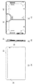
- FIG. 1 is a diagram showing an appearance of a liquid crystal television 10 according to the present embodiment.
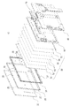
- FIG. 2 is an exploded perspective view of the liquid crystal television 10.
- the liquid crystal television 10 includes a frame-like frame 20 that is an exterior side cabinet, a front transparent protective cover 30, and a rear rear cabinet 40 as exteriors.
- a front cabinet frame 35, a sheet group 50, and a backlight chassis 60 are disposed inside the exteriors from the transparent protective cover 30 side.
- the frame 20 is a molded part made of a metal processed member (processing an extruded material or a drawn material). For example, in the 20 inch class, the approximate size is about 490 mm wide by about 290 mm high.
- the transparent protective cover 30 is a glass plate, for example, and protects the sheet group 50.
- the rear cabinet 40 is formed of a resin material.
- the front cabinet frame 35 is formed of a resin material in the same size and shape as the frame 20 and attached to the back side of the frame 20.
- the frame 20 is formed with a cylindrical positioning projection 25 extending in the rearward direction at a predetermined position.
- positioning boss holes 37 are provided on the front side of the front cabinet frame 35.
- a liquid crystal panel 51 In the sheet group 50, a liquid crystal panel 51, a Df sheet 52, a lens sheet 53, a light guide plate 54, a diffusion sheet 55, and a reflection plate 56 are arranged in a laminated form from the front side.
- the backlight chassis 60 is obtained by processing a metal plate into a predetermined shape, and a light source (for example, an LED edge light), a video drive circuit, a battery 70, and the like are arranged.
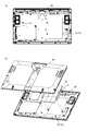
- FIG. 3A is a front view of the backlight chassis 60
- FIG. 3B is a perspective view of the backlight chassis 60
- the rear cabinet 40 and the battery 70 are also shown.
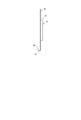
- FIG. 4 is a simplified side view of the backlight chassis 60 and shows a state in which the battery 70 and the light source 80 are mounted.
- the backlight chassis 60 has a backlight arrangement surface 81 provided in the lower part on the back side and a battery arrangement surface 73 provided on the front side.
- an LED edge light in which a plurality of LEDs (Light Emitting Diodes) are arranged as a light source 80 is attached.
- a battery 70 composed of nine cells 71 having three columns and three rows is attached to the battery arrangement surface 73.
- a hole 72 having a size substantially equal to that of the battery 70 is formed in the entire battery placement surface 73.
- the battery 70 is covered with a black package so that light from the light source 80 does not pass through, and is mounted in close contact with the battery placement surface 73 so that light from the light source 80 does not leak from the hole 72 formed in the battery placement surface 73.
- the battery placement surface 73 is provided on the surface opposite to the surface on which the light source 80 is attached in the backlight chassis 60 in order to reduce the influence of heat of the light source 80. Therefore, the heat of the light source 80 attached to the backlight arrangement surface 81 is transmitted through the backlight chassis 60 and conducted to the battery 70 attached to the battery arrangement surface 73. However, since the hole 72 is formed in the entire battery arrangement surface 73, heat conducted through the backlight chassis 60 is blocked in the hole 72 formed in the entire battery arrangement surface 73 and is conducted to the battery 70. Hard to do. Therefore, according to the present embodiment, the influence of the heat of the light source 80 on the battery 70 via the backlight chassis 60 can be reduced, and the deterioration of the cell 71 can be prevented.
- FIG. 5A is a front view of the backlight chassis 61
- FIG. 5B is a perspective view of the backlight chassis 61. In FIG. 5B, the rear cabinet 40 and the battery 70 are also shown.
- the battery arrangement surface 73 is divided into nine cell corresponding surfaces 74 in three columns and three rows corresponding to the position of each cell 71 of the battery 70.
- the cell corresponding surface 74 is arranged in parallel to the light source 80.
- each cell-corresponding surface 74 is formed with a larger hole 75 as it gets closer to the light source 80 according to the distance from the light source 80, so that the cell 71 closer to the light source 80 is ahead of the cell 71 farther from the light source 80. It is possible to prevent deterioration.
- the heat from the light source 80 is uniformly conducted to each cell 71 of the battery 70 through the backlight chassis 61, so that the degree of deterioration between the cells 71 can be made uniform. Further, by forming the holes 75 in the cell corresponding surface 74 according to each cell 71, the strength of the backlight chassis 61 is enhanced compared to the backlight chassis 60 in which the holes 72 are formed in the entire battery placement surface 73. be able to.
- the holes 75 formed in the cell corresponding surface 74 may be formed so that the temperature of each cell 71 is uniform, and the shape, size, and number thereof may be changed as appropriate.
- all the holes 75 formed in each cell-corresponding surface 74 have the same chrysanthemum shape (a shape with teeth inside the holes 75), and the chrysanthemum-shaped petals so that the temperatures between the cells 71 are equal.
- the opening area may be finely adjusted by bending or cutting (the teeth formed inside the hole 75).
- teeth may be attached to the inside of the hole 72 formed on the entire battery arrangement surface 73 so that the opening area of the hole 72 can be finely adjusted.
- the present invention is not limited to the above-described embodiment, and it goes without saying that various changes can be made without departing from the spirit of the present invention.
- the number and arrangement of cells constituting the battery 70 may be changed as appropriate.
- the present embodiment may be applied to a liquid crystal monitor or a mobile terminal (a mobile phone or a tablet display device). Note that, in the above-described embodiment, the same reference numerals are given to configurations showing similar functions.
Landscapes
- Engineering & Computer Science (AREA)
- Physics & Mathematics (AREA)
- Chemical & Material Sciences (AREA)
- Chemical Kinetics & Catalysis (AREA)
- Electrochemistry (AREA)
- General Chemical & Material Sciences (AREA)
- Manufacturing & Machinery (AREA)
- Theoretical Computer Science (AREA)
- General Physics & Mathematics (AREA)
- Nonlinear Science (AREA)
- General Engineering & Computer Science (AREA)
- Computer Hardware Design (AREA)
- Human Computer Interaction (AREA)
- Optics & Photonics (AREA)
- Mathematical Physics (AREA)
- Crystallography & Structural Chemistry (AREA)
- Life Sciences & Earth Sciences (AREA)
- Microelectronics & Electronic Packaging (AREA)
- Power Engineering (AREA)
- Thermal Sciences (AREA)
- Biophysics (AREA)
- Liquid Crystal (AREA)
- Planar Illumination Modules (AREA)
- Devices For Indicating Variable Information By Combining Individual Elements (AREA)
- Arrangement Of Elements, Cooling, Sealing, Or The Like Of Lighting Devices (AREA)
Abstract
本発明は、多数の電子部品が高密度に配置される場合でも、発熱源がバッテリーの性能に与える影響を低減する技術を提供することを目的とする。 本発明の液晶表示装置は、バックライトシャーシ(60)のバッテリー配置面(73)には、9つのセル(71)で構成されるバッテリー(70)が取り付けられている。バッテリー配置面(73)全体には孔(72)が形成されている。また、バックライトシャーシ(60)の背面下部には、光源が取り付けられている。光源の熱は、バックライトシャーシ(60)を伝わって、バッテリー配置面(73)に取り付けられたバッテリー(70)に伝導する。しかしながら、バッテリー配置面(73)全体には孔(72)が形成されているため、バックライトシャーシ(60)を伝導する熱は、バッテリー配置面(73)全体に設けられた孔(72)で断熱され、バッテリー(70)に伝導しにくく、セル(71)の劣化を防ぐことができる。
Description
本発明は、液晶表示装置に係り、特に、バッテリーを有し、持ち運びが可能な液晶表示装置に関する。
従来、持ち運び可能な電子機器の電源としてバッテリーが用いられることが多い。一般的に、バッテリーは、充電可能な複数のセルで構成されている。セルは、高温環境下で劣化しやすいため、発熱源の近くに位置するセルほど他のセルよりも劣化が進み、残容量が無くなりやすい。セルは、過放電させると破損等する虞があるため、いずれかのセルの残容量が無くなった時点で、他のセルに残容量が残っていたとしても放電を停止させる必要がある。この状態でセルを充電させると、セル間の残容量バランスが崩れているため、セル間で満充電となるタイミングに差が生じる。セルは、過充電によっても破損等する虞があるため、いずれかのセルが満充電に達した時点で、他のセルの充電を停止させる必要がある。その結果、さらにセル間の充電バランスが崩れ、バッテリー全体の性能が劣化することになる。
そのため、例えば、発熱源であるCPUからの熱がバッテリーの性能に与える影響を低減させるため、CPUとCPUに隣接するバッテリーとを離して配置することにより断熱空間を設けた可搬型電子機器が知られている(例えば、特許文献1を参照)。
しかしながら、近年の電子機器は、高機能化や小型化に伴い、電子機器内部に多数の電子部品が高密度に配置され、特許文献1のような断熱空間のためのスペースを確保しにくいという問題があった。
本発明は上記課題に鑑みてなされたものであり、多数の電子部品が高密度に配置される場合でも、発熱源がバッテリーの性能に与える影響を低減することができる技術を提供することを目的とする。
本発明の液晶表示装置は、光源が取り付けられたバックライトシャーシと、前記バックライトシャーシの前記光源が取り付けられた面とは反対の面に設けられたバッテリー配置面と、前記バッテリー配置面に形成された孔と、前記バッテリー配置面に取り付けられたバッテリーとを備えたことを特徴とする。また、前記孔は、前記バッテリーを構成するセルに対応して形成されてもよい。また、前記孔は、前記光源からの距離が近いほど大きく形成されてもよい。また、前記孔は、開口面積を調整可能とする形状を有してもよい。また、前記バッテリーは、黒色のパッケージで覆われ、前記バッテリー配置面に密接して取り付けられてもよい。
本発明によれば、多数の電子部品が高密度に配置される場合でも、発熱源がバッテリーの性能に与える影響を低減することができる。
以下、図を参照して本発明の実施形態を詳細に説明する。本実施形態では、液晶表示装置の一例として液晶テレビ10について説明する。
図1は、本実施形態に係る液晶テレビ10の外観を示す図である。また、図2は、液晶テレビ10の分解斜視図である。液晶テレビ10は、外装として外装側面キャビネットである枠状のフレーム20と、前側の透明保護カバー30と、後側のリアキャビネット40を備えている。そして、それら外装の内部には、透明保護カバー30側から、フロントキャビネット枠35、シート群50、バックライトシャーシ60が配置されている。
フレーム20は、金属製の加工部材(押し出し材または引き抜き材を加工)による成形部品である。例えば20インチクラスであれば、概略大きさは幅約490mm×高さ約290mmである。
透明保護カバー30は、例えばガラス板であって、シート群50を保護する。リアキャビネット40は、樹脂材で成形されている。
フロントキャビネット枠35は、フレーム20と略同様の大きさ及び形状に樹脂材で成形され、フレーム20の背面側に取り付けられる。なお、フレーム20には、所定位置に円柱状の位置決め用突部25が後ろ方向に延びて形成されている。位置決め用突部25に対応して、フロントキャビネット枠35の前面側には、位置決め用ボス穴37が設けられている。
シート群50は、前方側から液晶パネル51、Dfシート52、レンズシート53、導光板54、拡散シート55、反射板56が積層状に配置されている。
バックライトシャーシ60は、金属の板状体を所定形状に加工したものであって、光源(例えばLEDエッジライト)や、映像駆動回路、バッテリー70等が配置されている。
図3(a)は、バックライトシャーシ60の正面図であり、図3(b)は、バックライトシャーシ60の斜視図である。なお、図3(b)では、リアキャビネット40及びバッテリー70も示している。また、図4は、バックライトシャーシ60の簡易側面図であり、バッテリー70と光源80が装着された状態を示している。バックライトシャーシ60は、背面側下部に設けられたバックライト配置面81と正面側に設けられたバッテリー配置面73とを有している。
バックライト配置面81には、光源80として複数のLED(Light Emitting Diode)が配置されたLEDエッジライトが取り付けられている。
バッテリー配置面73には、縦3列横3行からなる9つのセル71で構成されるバッテリー70が取り付けられる。バッテリー配置面73全体にはバッテリー70と略等しい大きさの孔72が形成されている。バッテリー70は、光源80の光が透過しないよう黒色のパッケージで覆われており、バッテリー配置面73に形成された孔72から光源80の光が漏れないようバッテリー配置面73に密接して装着される。
バッテリー配置面73は、光源80の熱による影響を軽減するため、バックライトシャーシ60において光源80が取り付けられた面とは反対の面に設けられている。そのため、バックライト配置面81に取り付けられた光源80の熱は、バックライトシャーシ60を伝わって、バッテリー配置面73に取り付けられたバッテリー70に伝導する。しかしながら、バッテリー配置面73全体には孔72が形成されているため、バックライトシャーシ60を伝導する熱は、バッテリー配置面73全体に形成された孔72で伝熱が阻害され、バッテリー70に伝導しにくい。したがって、本実施形態によれば、光源80の熱がバックライトシャーシ60を介してバッテリー70に与える影響を軽減することができ、セル71の劣化を防止することができる。
ところで、光源80に近いほど周囲温度が高くなるため、バッテリー配置面73全体に形成された孔72により断熱効果を向上させても、各セル71の配置位置によってセル71間で若干温度のばらつきが残る。そこで、図5に示すバックライトシャーシ61では、バッテリー配置面73をバッテリー70の各セル71に対応する面(セル対応面74)に分割し、光源80に近づくにつれて各セル対応面74に形成された孔75による断熱効果が高くなるよう調整している。図5(a)は、バックライトシャーシ61の正面図であり、図5(b)は、バックライトシャーシ61の斜視図である。なお、図5(b)では、リアキャビネット40及びバッテリー70も示している。
バックライトシャーシ61では、バッテリー配置面73が、バッテリー70の各セル71の位置に対応して、縦3列横3行の9つのセル対応面74に分割されている。ここでは、セル対応面74が光源80に平行に配置されているものとする。
最も光源80に近い1行目のセル対応面74には、セル対応面74に形成される孔75の中で最も大きな孔75がそれぞれ2個ずつ形成されている。2番目に光源80に近い2行目のセル対応面74には、1行目のセル対応面74に形成された孔75よりも小さな孔75が2個ずつ形成されている。3番目に光源80に近い3行目のセル対応面74には、2行目に形成された孔75と同じ大きさの孔75が1つずつ形成されている。つまり、各セル対応面74には、光源80からの距離に応じて、光源80に近づくほど大きな孔75が形成されているため、光源80に近いセル71が光源80から遠いセル71よりも先に劣化することを防止することができる。
よって、光源80からの熱がバックライトシャーシ61を介してバッテリー70の各セル71に均等に伝導するため、セル71間の劣化度合いを均等にすることができる。また、各セル71に応じてセル対応面74に孔75を形成することで、バッテリー配置面73全体に孔72が形成されたバックライトシャーシ60に比べて、バックライトシャーシ61の強度を強化することができる。
なお、セル対応面74に形成される孔75は、各セル71の温度が均等になるように形成されればよく、適宜その形状、大きさ、数が変更されてもよい。例えば、各セル対応面74に形成される孔75をすべて同一の菊型(孔75の内側に歯が付いた形状)にして、セル71間の温度が均等になるように、菊型の花弁(孔75の内側に形成された歯)を折り曲げたり切り取ったりして開口面積を微調整できるようにしてもよい。なお、同様に、バッテリー配置面73全体に形成された孔72の内側に歯を付けて、孔72の開口面積を微調整できるようにしてもよい。
本発明は上述した実施の形態に限定されるものではなく、本発明の趣旨を逸脱しない範囲で種々様々に変更が可能であることは言うまでもない。例えば、バッテリー70を構成するセルの数及び配置は適宜変更されてもよい。また、本実施形態を液晶モニタや携帯端末(携帯電話やタブレット型表示装置)に適用してもよい。なお、上記実施形態において、同様の機能を示す構成には、同一の符号を付してある。
10:液晶テレビ(液晶表示装置)
20:フレーム
30:透明保護カバー
40:リアキャビネット
50:シート群
60,61:バックライトシャーシ
70:バッテリー
71:セル
72,75:孔
73:バッテリー配置面
74:セル対応面
80:光源
81:バックライト配置面
20:フレーム
30:透明保護カバー
40:リアキャビネット
50:シート群
60,61:バックライトシャーシ
70:バッテリー
71:セル
72,75:孔
73:バッテリー配置面
74:セル対応面
80:光源
81:バックライト配置面
Claims (5)
- 光源が取り付けられたバックライトシャーシと、
前記バックライトシャーシの前記光源が取り付けられた面とは反対の面に設けられたバッテリー配置面と、
前記バッテリー配置面に形成された孔と、
前記バッテリー配置面に取り付けられたバッテリーと、
を備えたことを特徴とする液晶表示装置。 - 前記孔は、前記バッテリーを構成するセルに対応して形成されていることを特徴とする請求項1に記載の液晶表示装置。
- 前記孔は、前記光源からの距離が近いほど大きく形成されていることを特徴とする請求項2に記載の液晶表示装置。
- 前記孔は、開口面積を調整可能とする形状を有していることを特徴とする請求項1から3までのいずれか1項に記載の液晶表示装置。
- 前記バッテリーは、黒色のパッケージで覆われ、前記バッテリー配置面に密接して取り付けられていることを特徴とする請求項1から4までのいずれか1項に液晶表示装置。
Priority Applications (2)
| Application Number | Priority Date | Filing Date | Title |
|---|---|---|---|
| US14/117,267 US20140204328A1 (en) | 2011-05-13 | 2012-04-02 | Liquid crystal display device |
| CN201280022944.8A CN103534636A (zh) | 2011-05-13 | 2012-04-02 | 液晶显示装置 |
Applications Claiming Priority (2)
| Application Number | Priority Date | Filing Date | Title |
|---|---|---|---|
| JP2011-107757 | 2011-05-13 | ||
| JP2011107757A JP5048147B1 (ja) | 2011-05-13 | 2011-05-13 | 液晶表示装置 |
Publications (1)
| Publication Number | Publication Date |
|---|---|
| WO2012157345A1 true WO2012157345A1 (ja) | 2012-11-22 |
Family
ID=47176686
Family Applications (1)
| Application Number | Title | Priority Date | Filing Date |
|---|---|---|---|
| PCT/JP2012/058856 Ceased WO2012157345A1 (ja) | 2011-05-13 | 2012-04-02 | 液晶表示装置 |
Country Status (4)
| Country | Link |
|---|---|
| US (1) | US20140204328A1 (ja) |
| JP (1) | JP5048147B1 (ja) |
| CN (1) | CN103534636A (ja) |
| WO (1) | WO2012157345A1 (ja) |
Families Citing this family (2)
| Publication number | Priority date | Publication date | Assignee | Title |
|---|---|---|---|---|
| WO2016038740A1 (ja) * | 2014-09-12 | 2016-03-17 | 堺ディスプレイプロダクト株式会社 | 光源装置及び表示装置 |
| US10231346B2 (en) * | 2016-05-27 | 2019-03-12 | Lg Electronics Inc. | Display device |
Citations (3)
| Publication number | Priority date | Publication date | Assignee | Title |
|---|---|---|---|---|
| JP2007329209A (ja) * | 2006-06-06 | 2007-12-20 | Sharp Corp | バッテリの放熱構造 |
| JP2008020865A (ja) * | 2006-07-14 | 2008-01-31 | Sharp Corp | シャーシ平面部の剛性を高める辺構造突起を有する電子機器 |
| JP2009229900A (ja) * | 2008-03-24 | 2009-10-08 | Furukawa Electric Co Ltd:The | 薄型ディスプレイ用のヒートシンク |
Family Cites Families (10)
| Publication number | Priority date | Publication date | Assignee | Title |
|---|---|---|---|---|
| US3830663A (en) * | 1973-03-05 | 1974-08-20 | Us Navy | Battery holder for satellite and method |
| US4825341A (en) * | 1987-11-17 | 1989-04-25 | Fiberstars, Inc. | Cooled lighting apparatus and method |
| US5406453A (en) * | 1993-04-01 | 1995-04-11 | Dell Usa, L.P. | Computer chassis planar/riser card assembly |
| JP2004163462A (ja) * | 2002-11-08 | 2004-06-10 | Sharp Corp | 液晶表示装置およびそれを備えた携帯用電子機器 |
| CN2809675Y (zh) * | 2005-06-30 | 2006-08-23 | 剩宜科技股份有限公司 | 载有薄化型电池的显示器 |
| TW200743854A (en) * | 2006-05-22 | 2007-12-01 | Au Optronics Corp | Backlight module and liquid crystal display including thereof |
| JP4553022B2 (ja) * | 2008-03-13 | 2010-09-29 | ソニー株式会社 | Ledバックライト装置 |
| CN102472457A (zh) * | 2009-09-04 | 2012-05-23 | 夏普株式会社 | 电子组件、照明装置、显示装置 |
| EP2942662B1 (en) * | 2009-12-23 | 2017-03-29 | LG Electronics, Inc. | Display device |
| JP4843721B2 (ja) * | 2010-04-30 | 2011-12-21 | 株式会社東芝 | テレビジョン装置、電子機器、および揺動支持機構 |
-
2011
- 2011-05-13 JP JP2011107757A patent/JP5048147B1/ja not_active Expired - Fee Related
-
2012
- 2012-04-02 CN CN201280022944.8A patent/CN103534636A/zh active Pending
- 2012-04-02 WO PCT/JP2012/058856 patent/WO2012157345A1/ja not_active Ceased
- 2012-04-02 US US14/117,267 patent/US20140204328A1/en not_active Abandoned
Patent Citations (3)
| Publication number | Priority date | Publication date | Assignee | Title |
|---|---|---|---|---|
| JP2007329209A (ja) * | 2006-06-06 | 2007-12-20 | Sharp Corp | バッテリの放熱構造 |
| JP2008020865A (ja) * | 2006-07-14 | 2008-01-31 | Sharp Corp | シャーシ平面部の剛性を高める辺構造突起を有する電子機器 |
| JP2009229900A (ja) * | 2008-03-24 | 2009-10-08 | Furukawa Electric Co Ltd:The | 薄型ディスプレイ用のヒートシンク |
Also Published As
| Publication number | Publication date |
|---|---|
| US20140204328A1 (en) | 2014-07-24 |
| JP2012237912A (ja) | 2012-12-06 |
| JP5048147B1 (ja) | 2012-10-17 |
| CN103534636A (zh) | 2014-01-22 |
Similar Documents
| Publication | Publication Date | Title |
|---|---|---|
| KR101881000B1 (ko) | 디스플레이 장치의 파손 방지 구조를 구비하는 휴대용 단말기 | |
| EP3832993A1 (en) | Handheld electronic device | |
| US10306114B2 (en) | Camera module mounting in an electronic device | |
| CN112911030A (zh) | 手持式电子设备 | |
| CN112909500A (zh) | 手持式电子设备 | |
| US20180234595A1 (en) | Camera Module | |
| CN102193219B (zh) | 显示装置及其组装方法 | |
| US8915606B2 (en) | Display device | |
| KR20170052760A (ko) | 표시장치 및 이의 제조 방법 | |
| WO2014021209A1 (ja) | 照明装置、表示装置、及びテレビ受信装置 | |
| WO2012035894A1 (ja) | 表示装置、液晶表示装置、および、テレビジョン受信機 | |
| KR101633125B1 (ko) | 표시장치 | |
| US20150042904A1 (en) | Display device and mobile terminal device | |
| JP5048147B1 (ja) | 液晶表示装置 | |
| TWI754422B (zh) | 具有指紋識別模組的顯示裝置 | |
| US8808895B2 (en) | Battery protection structures | |
| US20140085576A1 (en) | Light Guide Plates and Optical Films with Mating Alignment Features | |
| KR102226237B1 (ko) | 백라이트 유닛 및 이를 구비한 액정표시장치 | |
| CN113766781A (zh) | 盖板组件、显示屏及电子设备 | |
| JP2011257742A (ja) | 表示パネルユニット、電子機器 | |
| US9402325B2 (en) | Portable electronic device and method of protecting portable electronic device | |
| JP5089788B1 (ja) | 液晶表示装置 | |
| KR102084399B1 (ko) | 액정표시장치 및 그 제조방법 | |
| TW201547351A (zh) | 殼體及採用該殼體之移動終端 | |
| KR101646826B1 (ko) | 커브드 pcm |
Legal Events
| Date | Code | Title | Description |
|---|---|---|---|
| 121 | Ep: the epo has been informed by wipo that ep was designated in this application |
Ref document number: 12785135 Country of ref document: EP Kind code of ref document: A1 |
|
| WWE | Wipo information: entry into national phase |
Ref document number: 14117267 Country of ref document: US |
|
| NENP | Non-entry into the national phase |
Ref country code: DE |
|
| 122 | Ep: pct application non-entry in european phase |
Ref document number: 12785135 Country of ref document: EP Kind code of ref document: A1 |