WO2012157137A1 - Vehicle and method for controlling vehicle - Google Patents
Vehicle and method for controlling vehicle Download PDFInfo
- Publication number
- WO2012157137A1 WO2012157137A1 PCT/JP2011/077363 JP2011077363W WO2012157137A1 WO 2012157137 A1 WO2012157137 A1 WO 2012157137A1 JP 2011077363 W JP2011077363 W JP 2011077363W WO 2012157137 A1 WO2012157137 A1 WO 2012157137A1
- Authority
- WO
- WIPO (PCT)
- Prior art keywords
- power
- driving force
- vehicle
- storage device
- average
- Prior art date
Links
Images


Classifications
-
- B—PERFORMING OPERATIONS; TRANSPORTING
- B60—VEHICLES IN GENERAL
- B60L—PROPULSION OF ELECTRICALLY-PROPELLED VEHICLES; SUPPLYING ELECTRIC POWER FOR AUXILIARY EQUIPMENT OF ELECTRICALLY-PROPELLED VEHICLES; ELECTRODYNAMIC BRAKE SYSTEMS FOR VEHICLES IN GENERAL; MAGNETIC SUSPENSION OR LEVITATION FOR VEHICLES; MONITORING OPERATING VARIABLES OF ELECTRICALLY-PROPELLED VEHICLES; ELECTRIC SAFETY DEVICES FOR ELECTRICALLY-PROPELLED VEHICLES
- B60L58/00—Methods or circuit arrangements for monitoring or controlling batteries or fuel cells, specially adapted for electric vehicles
- B60L58/10—Methods or circuit arrangements for monitoring or controlling batteries or fuel cells, specially adapted for electric vehicles for monitoring or controlling batteries
- B60L58/12—Methods or circuit arrangements for monitoring or controlling batteries or fuel cells, specially adapted for electric vehicles for monitoring or controlling batteries responding to state of charge [SoC]
-
- B—PERFORMING OPERATIONS; TRANSPORTING
- B60—VEHICLES IN GENERAL
- B60L—PROPULSION OF ELECTRICALLY-PROPELLED VEHICLES; SUPPLYING ELECTRIC POWER FOR AUXILIARY EQUIPMENT OF ELECTRICALLY-PROPELLED VEHICLES; ELECTRODYNAMIC BRAKE SYSTEMS FOR VEHICLES IN GENERAL; MAGNETIC SUSPENSION OR LEVITATION FOR VEHICLES; MONITORING OPERATING VARIABLES OF ELECTRICALLY-PROPELLED VEHICLES; ELECTRIC SAFETY DEVICES FOR ELECTRICALLY-PROPELLED VEHICLES
- B60L15/00—Methods, circuits, or devices for controlling the traction-motor speed of electrically-propelled vehicles
- B60L15/20—Methods, circuits, or devices for controlling the traction-motor speed of electrically-propelled vehicles for control of the vehicle or its driving motor to achieve a desired performance, e.g. speed, torque, programmed variation of speed
- B60L15/2009—Methods, circuits, or devices for controlling the traction-motor speed of electrically-propelled vehicles for control of the vehicle or its driving motor to achieve a desired performance, e.g. speed, torque, programmed variation of speed for braking
-
- B—PERFORMING OPERATIONS; TRANSPORTING
- B60—VEHICLES IN GENERAL
- B60L—PROPULSION OF ELECTRICALLY-PROPELLED VEHICLES; SUPPLYING ELECTRIC POWER FOR AUXILIARY EQUIPMENT OF ELECTRICALLY-PROPELLED VEHICLES; ELECTRODYNAMIC BRAKE SYSTEMS FOR VEHICLES IN GENERAL; MAGNETIC SUSPENSION OR LEVITATION FOR VEHICLES; MONITORING OPERATING VARIABLES OF ELECTRICALLY-PROPELLED VEHICLES; ELECTRIC SAFETY DEVICES FOR ELECTRICALLY-PROPELLED VEHICLES
- B60L3/00—Electric devices on electrically-propelled vehicles for safety purposes; Monitoring operating variables, e.g. speed, deceleration or energy consumption
- B60L3/12—Recording operating variables ; Monitoring of operating variables
-
- B—PERFORMING OPERATIONS; TRANSPORTING
- B60—VEHICLES IN GENERAL
- B60L—PROPULSION OF ELECTRICALLY-PROPELLED VEHICLES; SUPPLYING ELECTRIC POWER FOR AUXILIARY EQUIPMENT OF ELECTRICALLY-PROPELLED VEHICLES; ELECTRODYNAMIC BRAKE SYSTEMS FOR VEHICLES IN GENERAL; MAGNETIC SUSPENSION OR LEVITATION FOR VEHICLES; MONITORING OPERATING VARIABLES OF ELECTRICALLY-PROPELLED VEHICLES; ELECTRIC SAFETY DEVICES FOR ELECTRICALLY-PROPELLED VEHICLES
- B60L50/00—Electric propulsion with power supplied within the vehicle
- B60L50/10—Electric propulsion with power supplied within the vehicle using propulsion power supplied by engine-driven generators, e.g. generators driven by combustion engines
- B60L50/16—Electric propulsion with power supplied within the vehicle using propulsion power supplied by engine-driven generators, e.g. generators driven by combustion engines with provision for separate direct mechanical propulsion
-
- B—PERFORMING OPERATIONS; TRANSPORTING
- B60—VEHICLES IN GENERAL
- B60L—PROPULSION OF ELECTRICALLY-PROPELLED VEHICLES; SUPPLYING ELECTRIC POWER FOR AUXILIARY EQUIPMENT OF ELECTRICALLY-PROPELLED VEHICLES; ELECTRODYNAMIC BRAKE SYSTEMS FOR VEHICLES IN GENERAL; MAGNETIC SUSPENSION OR LEVITATION FOR VEHICLES; MONITORING OPERATING VARIABLES OF ELECTRICALLY-PROPELLED VEHICLES; ELECTRIC SAFETY DEVICES FOR ELECTRICALLY-PROPELLED VEHICLES
- B60L50/00—Electric propulsion with power supplied within the vehicle
- B60L50/40—Electric propulsion with power supplied within the vehicle using propulsion power supplied by capacitors
-
- B—PERFORMING OPERATIONS; TRANSPORTING
- B60—VEHICLES IN GENERAL
- B60L—PROPULSION OF ELECTRICALLY-PROPELLED VEHICLES; SUPPLYING ELECTRIC POWER FOR AUXILIARY EQUIPMENT OF ELECTRICALLY-PROPELLED VEHICLES; ELECTRODYNAMIC BRAKE SYSTEMS FOR VEHICLES IN GENERAL; MAGNETIC SUSPENSION OR LEVITATION FOR VEHICLES; MONITORING OPERATING VARIABLES OF ELECTRICALLY-PROPELLED VEHICLES; ELECTRIC SAFETY DEVICES FOR ELECTRICALLY-PROPELLED VEHICLES
- B60L7/00—Electrodynamic brake systems for vehicles in general
- B60L7/10—Dynamic electric regenerative braking
- B60L7/14—Dynamic electric regenerative braking for vehicles propelled by ac motors
-
- B—PERFORMING OPERATIONS; TRANSPORTING
- B60—VEHICLES IN GENERAL
- B60W—CONJOINT CONTROL OF VEHICLE SUB-UNITS OF DIFFERENT TYPE OR DIFFERENT FUNCTION; CONTROL SYSTEMS SPECIALLY ADAPTED FOR HYBRID VEHICLES; ROAD VEHICLE DRIVE CONTROL SYSTEMS FOR PURPOSES NOT RELATED TO THE CONTROL OF A PARTICULAR SUB-UNIT
- B60W20/00—Control systems specially adapted for hybrid vehicles
-
- B—PERFORMING OPERATIONS; TRANSPORTING
- B60—VEHICLES IN GENERAL
- B60L—PROPULSION OF ELECTRICALLY-PROPELLED VEHICLES; SUPPLYING ELECTRIC POWER FOR AUXILIARY EQUIPMENT OF ELECTRICALLY-PROPELLED VEHICLES; ELECTRODYNAMIC BRAKE SYSTEMS FOR VEHICLES IN GENERAL; MAGNETIC SUSPENSION OR LEVITATION FOR VEHICLES; MONITORING OPERATING VARIABLES OF ELECTRICALLY-PROPELLED VEHICLES; ELECTRIC SAFETY DEVICES FOR ELECTRICALLY-PROPELLED VEHICLES
- B60L2210/00—Converter types
- B60L2210/10—DC to DC converters
-
- B—PERFORMING OPERATIONS; TRANSPORTING
- B60—VEHICLES IN GENERAL
- B60L—PROPULSION OF ELECTRICALLY-PROPELLED VEHICLES; SUPPLYING ELECTRIC POWER FOR AUXILIARY EQUIPMENT OF ELECTRICALLY-PROPELLED VEHICLES; ELECTRODYNAMIC BRAKE SYSTEMS FOR VEHICLES IN GENERAL; MAGNETIC SUSPENSION OR LEVITATION FOR VEHICLES; MONITORING OPERATING VARIABLES OF ELECTRICALLY-PROPELLED VEHICLES; ELECTRIC SAFETY DEVICES FOR ELECTRICALLY-PROPELLED VEHICLES
- B60L2210/00—Converter types
- B60L2210/40—DC to AC converters
-
- B—PERFORMING OPERATIONS; TRANSPORTING
- B60—VEHICLES IN GENERAL
- B60L—PROPULSION OF ELECTRICALLY-PROPELLED VEHICLES; SUPPLYING ELECTRIC POWER FOR AUXILIARY EQUIPMENT OF ELECTRICALLY-PROPELLED VEHICLES; ELECTRODYNAMIC BRAKE SYSTEMS FOR VEHICLES IN GENERAL; MAGNETIC SUSPENSION OR LEVITATION FOR VEHICLES; MONITORING OPERATING VARIABLES OF ELECTRICALLY-PROPELLED VEHICLES; ELECTRIC SAFETY DEVICES FOR ELECTRICALLY-PROPELLED VEHICLES
- B60L2220/00—Electrical machine types; Structures or applications thereof
- B60L2220/10—Electrical machine types
- B60L2220/14—Synchronous machines
-
- B—PERFORMING OPERATIONS; TRANSPORTING
- B60—VEHICLES IN GENERAL
- B60L—PROPULSION OF ELECTRICALLY-PROPELLED VEHICLES; SUPPLYING ELECTRIC POWER FOR AUXILIARY EQUIPMENT OF ELECTRICALLY-PROPELLED VEHICLES; ELECTRODYNAMIC BRAKE SYSTEMS FOR VEHICLES IN GENERAL; MAGNETIC SUSPENSION OR LEVITATION FOR VEHICLES; MONITORING OPERATING VARIABLES OF ELECTRICALLY-PROPELLED VEHICLES; ELECTRIC SAFETY DEVICES FOR ELECTRICALLY-PROPELLED VEHICLES
- B60L2240/00—Control parameters of input or output; Target parameters
- B60L2240/10—Vehicle control parameters
- B60L2240/12—Speed
-
- B—PERFORMING OPERATIONS; TRANSPORTING
- B60—VEHICLES IN GENERAL
- B60L—PROPULSION OF ELECTRICALLY-PROPELLED VEHICLES; SUPPLYING ELECTRIC POWER FOR AUXILIARY EQUIPMENT OF ELECTRICALLY-PROPELLED VEHICLES; ELECTRODYNAMIC BRAKE SYSTEMS FOR VEHICLES IN GENERAL; MAGNETIC SUSPENSION OR LEVITATION FOR VEHICLES; MONITORING OPERATING VARIABLES OF ELECTRICALLY-PROPELLED VEHICLES; ELECTRIC SAFETY DEVICES FOR ELECTRICALLY-PROPELLED VEHICLES
- B60L2240/00—Control parameters of input or output; Target parameters
- B60L2240/60—Navigation input
- B60L2240/64—Road conditions
- B60L2240/642—Slope of road
-
- B—PERFORMING OPERATIONS; TRANSPORTING
- B60—VEHICLES IN GENERAL
- B60L—PROPULSION OF ELECTRICALLY-PROPELLED VEHICLES; SUPPLYING ELECTRIC POWER FOR AUXILIARY EQUIPMENT OF ELECTRICALLY-PROPELLED VEHICLES; ELECTRODYNAMIC BRAKE SYSTEMS FOR VEHICLES IN GENERAL; MAGNETIC SUSPENSION OR LEVITATION FOR VEHICLES; MONITORING OPERATING VARIABLES OF ELECTRICALLY-PROPELLED VEHICLES; ELECTRIC SAFETY DEVICES FOR ELECTRICALLY-PROPELLED VEHICLES
- B60L2250/00—Driver interactions
- B60L2250/16—Driver interactions by display
-
- B—PERFORMING OPERATIONS; TRANSPORTING
- B60—VEHICLES IN GENERAL
- B60L—PROPULSION OF ELECTRICALLY-PROPELLED VEHICLES; SUPPLYING ELECTRIC POWER FOR AUXILIARY EQUIPMENT OF ELECTRICALLY-PROPELLED VEHICLES; ELECTRODYNAMIC BRAKE SYSTEMS FOR VEHICLES IN GENERAL; MAGNETIC SUSPENSION OR LEVITATION FOR VEHICLES; MONITORING OPERATING VARIABLES OF ELECTRICALLY-PROPELLED VEHICLES; ELECTRIC SAFETY DEVICES FOR ELECTRICALLY-PROPELLED VEHICLES
- B60L2250/00—Driver interactions
- B60L2250/26—Driver interactions by pedal actuation
-
- B—PERFORMING OPERATIONS; TRANSPORTING
- B60—VEHICLES IN GENERAL
- B60L—PROPULSION OF ELECTRICALLY-PROPELLED VEHICLES; SUPPLYING ELECTRIC POWER FOR AUXILIARY EQUIPMENT OF ELECTRICALLY-PROPELLED VEHICLES; ELECTRODYNAMIC BRAKE SYSTEMS FOR VEHICLES IN GENERAL; MAGNETIC SUSPENSION OR LEVITATION FOR VEHICLES; MONITORING OPERATING VARIABLES OF ELECTRICALLY-PROPELLED VEHICLES; ELECTRIC SAFETY DEVICES FOR ELECTRICALLY-PROPELLED VEHICLES
- B60L2260/00—Operating Modes
- B60L2260/40—Control modes
- B60L2260/42—Control modes by adaptive correction
-
- B—PERFORMING OPERATIONS; TRANSPORTING
- B60—VEHICLES IN GENERAL
- B60L—PROPULSION OF ELECTRICALLY-PROPELLED VEHICLES; SUPPLYING ELECTRIC POWER FOR AUXILIARY EQUIPMENT OF ELECTRICALLY-PROPELLED VEHICLES; ELECTRODYNAMIC BRAKE SYSTEMS FOR VEHICLES IN GENERAL; MAGNETIC SUSPENSION OR LEVITATION FOR VEHICLES; MONITORING OPERATING VARIABLES OF ELECTRICALLY-PROPELLED VEHICLES; ELECTRIC SAFETY DEVICES FOR ELECTRICALLY-PROPELLED VEHICLES
- B60L2260/00—Operating Modes
- B60L2260/40—Control modes
- B60L2260/50—Control modes by future state prediction
- B60L2260/52—Control modes by future state prediction drive range estimation, e.g. of estimation of available travel distance
-
- B—PERFORMING OPERATIONS; TRANSPORTING
- B60—VEHICLES IN GENERAL
- B60L—PROPULSION OF ELECTRICALLY-PROPELLED VEHICLES; SUPPLYING ELECTRIC POWER FOR AUXILIARY EQUIPMENT OF ELECTRICALLY-PROPELLED VEHICLES; ELECTRODYNAMIC BRAKE SYSTEMS FOR VEHICLES IN GENERAL; MAGNETIC SUSPENSION OR LEVITATION FOR VEHICLES; MONITORING OPERATING VARIABLES OF ELECTRICALLY-PROPELLED VEHICLES; ELECTRIC SAFETY DEVICES FOR ELECTRICALLY-PROPELLED VEHICLES
- B60L2260/00—Operating Modes
- B60L2260/40—Control modes
- B60L2260/50—Control modes by future state prediction
- B60L2260/54—Energy consumption estimation
-
- Y—GENERAL TAGGING OF NEW TECHNOLOGICAL DEVELOPMENTS; GENERAL TAGGING OF CROSS-SECTIONAL TECHNOLOGIES SPANNING OVER SEVERAL SECTIONS OF THE IPC; TECHNICAL SUBJECTS COVERED BY FORMER USPC CROSS-REFERENCE ART COLLECTIONS [XRACs] AND DIGESTS
- Y02—TECHNOLOGIES OR APPLICATIONS FOR MITIGATION OR ADAPTATION AGAINST CLIMATE CHANGE
- Y02T—CLIMATE CHANGE MITIGATION TECHNOLOGIES RELATED TO TRANSPORTATION
- Y02T10/00—Road transport of goods or passengers
- Y02T10/60—Other road transportation technologies with climate change mitigation effect
- Y02T10/64—Electric machine technologies in electromobility
-
- Y—GENERAL TAGGING OF NEW TECHNOLOGICAL DEVELOPMENTS; GENERAL TAGGING OF CROSS-SECTIONAL TECHNOLOGIES SPANNING OVER SEVERAL SECTIONS OF THE IPC; TECHNICAL SUBJECTS COVERED BY FORMER USPC CROSS-REFERENCE ART COLLECTIONS [XRACs] AND DIGESTS
- Y02—TECHNOLOGIES OR APPLICATIONS FOR MITIGATION OR ADAPTATION AGAINST CLIMATE CHANGE
- Y02T—CLIMATE CHANGE MITIGATION TECHNOLOGIES RELATED TO TRANSPORTATION
- Y02T10/00—Road transport of goods or passengers
- Y02T10/60—Other road transportation technologies with climate change mitigation effect
- Y02T10/70—Energy storage systems for electromobility, e.g. batteries
-
- Y—GENERAL TAGGING OF NEW TECHNOLOGICAL DEVELOPMENTS; GENERAL TAGGING OF CROSS-SECTIONAL TECHNOLOGIES SPANNING OVER SEVERAL SECTIONS OF THE IPC; TECHNICAL SUBJECTS COVERED BY FORMER USPC CROSS-REFERENCE ART COLLECTIONS [XRACs] AND DIGESTS
- Y02—TECHNOLOGIES OR APPLICATIONS FOR MITIGATION OR ADAPTATION AGAINST CLIMATE CHANGE
- Y02T—CLIMATE CHANGE MITIGATION TECHNOLOGIES RELATED TO TRANSPORTATION
- Y02T10/00—Road transport of goods or passengers
- Y02T10/60—Other road transportation technologies with climate change mitigation effect
- Y02T10/7072—Electromobility specific charging systems or methods for batteries, ultracapacitors, supercapacitors or double-layer capacitors
-
- Y—GENERAL TAGGING OF NEW TECHNOLOGICAL DEVELOPMENTS; GENERAL TAGGING OF CROSS-SECTIONAL TECHNOLOGIES SPANNING OVER SEVERAL SECTIONS OF THE IPC; TECHNICAL SUBJECTS COVERED BY FORMER USPC CROSS-REFERENCE ART COLLECTIONS [XRACs] AND DIGESTS
- Y02—TECHNOLOGIES OR APPLICATIONS FOR MITIGATION OR ADAPTATION AGAINST CLIMATE CHANGE
- Y02T—CLIMATE CHANGE MITIGATION TECHNOLOGIES RELATED TO TRANSPORTATION
- Y02T10/00—Road transport of goods or passengers
- Y02T10/60—Other road transportation technologies with climate change mitigation effect
- Y02T10/72—Electric energy management in electromobility
-
- Y—GENERAL TAGGING OF NEW TECHNOLOGICAL DEVELOPMENTS; GENERAL TAGGING OF CROSS-SECTIONAL TECHNOLOGIES SPANNING OVER SEVERAL SECTIONS OF THE IPC; TECHNICAL SUBJECTS COVERED BY FORMER USPC CROSS-REFERENCE ART COLLECTIONS [XRACs] AND DIGESTS
- Y02—TECHNOLOGIES OR APPLICATIONS FOR MITIGATION OR ADAPTATION AGAINST CLIMATE CHANGE
- Y02T—CLIMATE CHANGE MITIGATION TECHNOLOGIES RELATED TO TRANSPORTATION
- Y02T90/00—Enabling technologies or technologies with a potential or indirect contribution to GHG emissions mitigation
- Y02T90/10—Technologies relating to charging of electric vehicles
- Y02T90/16—Information or communication technologies improving the operation of electric vehicles
-
- Y—GENERAL TAGGING OF NEW TECHNOLOGICAL DEVELOPMENTS; GENERAL TAGGING OF CROSS-SECTIONAL TECHNOLOGIES SPANNING OVER SEVERAL SECTIONS OF THE IPC; TECHNICAL SUBJECTS COVERED BY FORMER USPC CROSS-REFERENCE ART COLLECTIONS [XRACs] AND DIGESTS
- Y10—TECHNICAL SUBJECTS COVERED BY FORMER USPC
- Y10S—TECHNICAL SUBJECTS COVERED BY FORMER USPC CROSS-REFERENCE ART COLLECTIONS [XRACs] AND DIGESTS
- Y10S903/00—Hybrid electric vehicles, HEVS
- Y10S903/902—Prime movers comprising electrical and internal combustion motors
- Y10S903/903—Prime movers comprising electrical and internal combustion motors having energy storing means, e.g. battery, capacitor
Definitions
- the present invention relates to a vehicle and a vehicle control method, and more particularly to estimation control of a travelable distance in a vehicle that generates a travel driving force using electric power from a power storage device.
- a vehicle that is mounted with a power storage device (for example, a secondary battery or a capacitor) and travels by driving force generated by a motor using electric power stored in the power storage device as an environment-friendly vehicle.
- a power storage device for example, a secondary battery or a capacitor
- Such vehicles include, for example, electric vehicles, hybrid vehicles, fuel cell vehicles, and the like.
- Patent Document 1 in an electric vehicle that travels regularly on a steady route, the remaining power storage based on the power consumption and cruising distance at the previous travel of the steady route.
- Patent Document 1 A technique for calculating a cruising distance with the power of the apparatus and determining whether or not the vehicle can travel to a destination is disclosed.
- Patent Document 1 the power consumption may be different even on the same travel route depending on how the user who drives the vehicle travels. Even if the travelable distance is calculated based on the information at the time of the previous travel, the accuracy is not necessarily high.
- the travelable distance calculated based on the state at the time of the previous driving for a specific steady route is It may not properly reflect the changing current vehicle conditions.
- the present invention has been made to solve such problems, and an object of the present invention is to be able to travel with the remaining capacity of the power storage device in a vehicle that generates a driving force using the power from the power storage device. It is to estimate the distance appropriately.
- the vehicle according to the present invention includes a rotating electrical machine and a control device, and can travel using the electric power of the installed power storage device.
- the rotating electrical machine generates traveling driving force using electric power from the power storage device.
- the control device calculates the first power consumption based on an average operating point determined from an average vehicle speed and an average driving force for each predetermined period when traveling with electric power from the power storage device, and is determined in advance.
- the second power consumption is calculated based on the power consumption and the travel distance during the period, and the vehicle can travel with the power remaining in the power storage device based on the first and second power costs and the state of charge of the power storage device. Calculate the distance.
- control device calculates a correction coefficient from the first and second power costs, calculates a predicted power cost by correcting the first power cost using the correction coefficient, and calculates the predicted power cost and the state of charge of the power storage device.
- the travelable distance is calculated based on the above.
- the correction coefficient is calculated based on a ratio of the second power consumption to the first power consumption.
- control device calculates the predicted power consumption based on the operating point that has been corrected so as to smooth the average operating point in the time axis direction using a predetermined time constant.
- control device smoothes the average vehicle speed and the average driving force using different time constants.
- the time constant for the average vehicle speed is smaller than the time constant for the average driving force.
- control device smoothes the average vehicle speed using different time constants for the driving force required from the road surface gradient of the driving force and the remaining driving force.
- the rotating electrical machine is coupled to the drive wheel and can generate power by the rotational force of the drive wheel.
- the control device calculates the second power consumption based on the distance traveled in a state where the power generated by the rotating electrical machine is below the threshold value among the travel distance.
- the vehicle further includes an engine.
- the traveling driving force is output using the driving force from the rotating electrical machine and the driving force from the engine.
- the control device calculates a travelable distance when the engine is in a non-driving state.
- the vehicle further includes a display unit for notifying the user of the travelable distance.
- the vehicle control method according to the present invention is a control method for a vehicle that can travel using the electric power of the installed power storage device.
- the vehicle includes a rotating electrical machine for generating travel driving force using electric power from the power storage device.
- the control method includes a step of calculating a first power consumption based on an average operating point determined from an average vehicle speed and an average driving force for each predetermined period when traveling with electric power from the power storage device;
- the second power consumption is calculated based on the power consumption and the travel distance during the specified period, and the vehicle can travel with the power remaining in the power storage device based on the first and second power costs and the charge state of the power storage device. Calculating a possible travel distance.
- the present invention it is possible to appropriately estimate the distance that can be traveled by the remaining capacity of the power storage device in the vehicle that generates the driving force using the power from the power storage device.
- 1 is an overall block diagram of a vehicle according to an embodiment. It is a figure for demonstrating the relationship between a vehicle speed, a driving force, and electricity consumption. It is a 1st figure for demonstrating the relationship between a road surface gradient and driving force. It is a 2nd figure for demonstrating the relationship between a road surface gradient and driving force.
- it is a functional block diagram for demonstrating estimation control of the travelable distance performed by ECU.
- it is a flowchart for demonstrating the detail of the estimation control process of the travelable distance performed by ECU.
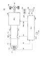
- FIG. 1 is an overall block diagram of vehicle 100 according to the present embodiment.
- vehicle 100 includes a power storage device 110, a voltage sensor 111, a current sensor 112, a system main relay (SMR) 115, and a PCU (Power Control Unit) 120 that is a driving device.
- SMR system main relay
- PCU Power Control Unit
- ECU Electronic Control Unit
- the power storage device 110 is a power storage element configured to be chargeable / dischargeable.
- the power storage device 110 includes, for example, a secondary battery such as a lithium ion battery, a nickel hydride battery, or a lead storage battery, or a power storage element such as an electric double layer capacitor.
- the power storage device 110 is connected to the PCU 120 via the power line PL1 and the ground line NL1. Then, power storage device 110 supplies power for generating driving force of vehicle 100 to PCU 120.
- the power storage device 110 stores the electric power generated by the motor generator 130.
- the output of power storage device 110 is, for example, about 200V.
- Voltage sensor 111 detects voltage VB of power storage device 110 and outputs the detection result to ECU 300.
- Current sensor 112 detects current IB input to and output from the power storage device, and outputs the detected value to ECU 300.
- the relays included in the SMR 115 are inserted into the power line PL1 and the ground line NL1 that connect the power storage device 110 and the PCU 120, respectively.
- SMR 115 switches between power supply and cutoff between power storage device 110 and PCU 120 based on control signal SE ⁇ b> 1 from ECU 300.
- the PCU 120 includes a converter, an inverter, etc., although none are shown.
- the converter is controlled by a control signal PWC from ECU 300 to convert the voltage from power storage device 110.
- the inverter is controlled by a control signal PWI from ECU 300 and drives motor generator 130 using electric power converted by the converter.
- the motor generator 130 is an AC rotating electric machine, for example, a permanent magnet type synchronous motor including a rotor in which a permanent magnet is embedded.
- the output torque of the motor generator 130 is transmitted to the drive wheels 140 to cause the vehicle 100 to travel.
- the motor generator 130 can generate electric power by the rotational force of the drive wheels 140 during the regenerative braking operation of the vehicle 100. Then, the generated power is converted into charging power for power storage device 110 by PCU 120.
- a necessary vehicle driving force is generated by operating the engine and the motor generator 130 in a coordinated manner.
- vehicle 100 in the present embodiment represents a vehicle equipped with an electric motor for generating vehicle driving force, and is a hybrid vehicle that generates vehicle driving force by an engine and an electric motor, an electric vehicle that is not equipped with an engine, and Includes fuel cell vehicles.
- Display unit 150 displays various types of information to the user based on control signal DSP from ECU 300.
- the speed sensor 160 detects a signal VEL related to the vehicle speed of the vehicle 100 and outputs it to the ECU 300.
- Speed sensor 160 may be, for example, a rotation angle sensor for detecting the rotation angle of motor generator 130, or may be a speed sensor for detecting the rotation speed of drive wheel 140.
- the inclination sensor 170 is a sensor for detecting the inclination of the road surface when the vehicle 100 is traveling on a slope, and includes, for example, an acceleration sensor. Inclination sensor 170 outputs an inclination signal INC indicating the detected inclination of the road surface to ECU 300.
- ECU 300 includes a CPU (Central Processing Unit), a storage device, and an input / output buffer (not shown in FIG. 1).
- the ECU 300 inputs a signal from each sensor and outputs a control signal to each device. 100 and each device are controlled. Note that these controls are not limited to processing by software, and can be processed by dedicated hardware (electronic circuit).
- ECU 300 receives detection values of voltage VB and current IB of power storage device 110 from voltage sensor 111 and current sensor 112. ECU 300 calculates the state of charge of power storage device 110 (hereinafter also referred to as SOC (State of Charge)) based on voltage VB and current IB.
- SOC State of Charge
- ECU 300 also receives a signal ACC indicating the amount of operation of accelerator pedal 180. ECU 300 calculates the vehicle driving force requested by the user based on the operation amount ACC of accelerator pedal 180.
- the charging of the power storage device 110 in the vehicle 100 as described above is not completed in a short time as in the case of refueling in a vehicle traveling by an engine, and a relatively long time is required.
- FIG. 2 is a diagram for explaining the relationship among the vehicle speed, driving force, and power consumption in the vehicle 100.
- the vehicle speed VEL is shown on the horizontal axis
- the driving force FRC is shown on the vertical axis.
- a curve W10 in FIG. 2 indicates the maximum driving force that can be output at each vehicle speed VEL.
- Curves W11 to W15 in FIG. 2 indicate the amount of power consumed per unit travel distance, so-called power consumption (Wh / km), and generally means that energy efficiency is better when power consumption is smaller. .
- FIG. 2 in an electric vehicle such as vehicle 100 shown in FIG. 1 or in a hybrid vehicle, when the engine is stopped and the vehicle travels only with the electric power from the power storage device, there is a power consumption in steady traveling. It is known that it is determined almost uniquely by an operating point (for example, point P10 in FIG. 2) determined by the average vehicle speed Vave and the average driving force Fave in the time interval.
- an operating point for example, point P10 in FIG. 2
- the power consumption can vary between when traveling on a flat ground and when traveling on a sloped road surface such as a mountain road.
- the travelable distance based on the remaining capacity of the power storage device is calculated using the power consumption determined from the operating point determined by the average vehicle speed Vave and the average driving force Fave, the calculated travelable distance is determined by the user's driving method. Since the road surface condition (so-called soot) is not properly reflected, it may become unreliable.
- the influence of the user's driving method and the road surface condition is reflected in the electricity cost.
- the calculated correction coefficient is directly reflected as it is, the rapid increase / decrease in power consumption may frequently be repeated in a short period of time, and the travelable distance frequently changes accordingly. There is a risk that the reliability of the traveled distance will be reduced.
- the degree of smoothing that is, the time constant is changed depending on the use of the driving force.
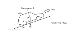
- FIG. 3 is a first diagram for explaining the relationship between the road surface gradient and the driving force.
- the mass of vehicle 100 is represented by m and the acceleration of gravity is represented by g, which counters components along the slope of gravity applied to vehicle 100.
- the driving force Finc required for this can be expressed by the following equation (1).
- the total driving force Ftotal to be output by the vehicle 100 is expressed by the following equation (2). I can express.
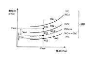
- FIG. 4 is a diagram for explaining the change of the average operating point and the driving force in the map as shown in FIG.
- curves W21 to W24 indicate the vehicle speed VEL and the driving force FRC required for a constant road surface gradient, respectively.
- the driving force from the point P22 to the point P21 on the curve W24 among the driving force changed from the point P22 to the point P20 is the road surface.
- the driving force Facc required for acceleration and speed maintenance is continued for a relatively long period in order to maintain traveling in the time interval for obtaining the operating point.
- the driving force Finc necessary to counter the gravity caused by the road surface gradient is usually output for a relatively short time compared to the driving force Facc, except when the slope continues for a long distance. .
- the driving force Finc for the road surface gradient is set so that the time constant is larger than the driving force Facc for the vehicle speed, and by changing more slowly, the stability of the estimated value of the travelable distance is improved. Further, the reliability of the estimated value of the travelable distance can be improved. That is, since the driving force Facc with respect to the vehicle speed having a high relevance to the user's driving operation is easily reflected in the calculation result, the average operating point can be calculated in consideration of the user's driving force.
- FIG. 5 is a functional block diagram for explaining the estimation control of the travelable distance executed by the ECU 300 in the present embodiment.
- Each functional block described in the functional block diagram of FIG. 5 is realized by hardware or software processing by ECU 300.
- ECU 300 includes an average operating point determination unit 310, an actual electricity cost calculation unit 320, a reference electricity cost calculation unit 330, a correction coefficient calculation unit 340, a smoothing processing unit 350, a running A possible distance calculation unit 360 and a display control unit 370 are included.
- the average operating point determination unit 310 receives the operation amount ACC of the accelerator pedal 180 and the vehicle speed VEL from the speed sensor 160. Based on the operation amount ACC of the accelerator pedal 180, the average driving force Fave at a predetermined time interval is calculated, and the average vehicle speed Vave at the predetermined time interval is calculated from the vehicle speed VEL. Then, the average operating point determination unit 310 outputs the calculated average vehicle speed Vave and average driving force Fave to the reference power consumption calculation unit 330 and the smoothing processing unit 350.
- the reference power consumption calculation unit 330 receives the average vehicle speed Vave and the average driving force Fave from the average operating point determination unit 310.
- the reference power consumption calculation unit 330 calculates a reference power consumption EC_ave in a standard state based on the average vehicle speed Vave and the average driving force Fave using a predetermined map as shown in FIG. Then, the reference power consumption calculation unit 330 outputs the calculated reference power consumption EC_ave to the correction coefficient calculation unit 340.
- Actual power consumption calculation unit 320 receives voltage VB, current IB, and vehicle speed VEL of power storage device 110. Based on these pieces of information, the actual electricity cost calculation unit 320 calculates the actual electricity cost EC_real at the predetermined time interval. Then, the actual power consumption calculation unit 320 outputs the calculated actual power consumption EC_real to the correction coefficient calculation unit 340.
- the correction coefficient calculation unit 340 receives the reference electricity cost EC_ave from the reference electricity cost calculation unit 330 and the actual electricity cost EC_real from the actual electricity cost calculation unit 320. Based on this information, the correction coefficient calculation unit 340 calculates a correction coefficient K for reflecting the difference between the standard power consumption EC_ave and the actual power consumption EC_real in the map as shown in FIG. Output.
- the correction coefficient K can be defined as the ratio of the actual electricity cost EC_real to the reference electricity cost EC_ave, as shown in Expression (3).
- Smoothing processing unit 350 receives correction coefficient K from correction coefficient calculation unit 340, average vehicle speed Vave and average driving force Fave from average operating point determination unit 310, and inclination signal INC from inclination sensor 170.
- the smoothing processing unit 350 performs a smoothing process on these pieces of information so that the change from the previous calculation result to the current calculation value does not become abrupt. For example, for the correction coefficient K, if the previous calculation result is K (n ⁇ 1), the current calculation value is K, and the calculation result after smoothing is K (n), the time constant ⁇ is used. It can be calculated as in equation (4).
- K (n) K (n ⁇ 1) + ⁇ ⁇ KK (n ⁇ 1) ⁇ (4)
- the smoothing processing unit 350 executes a learning calculation for the correction coefficient K, the average vehicle speed Vave, the average driving force Fave, and the tilt signal INC.
- the time constant for each item can be set individually. Each of these time constants may be the same value as the others, or may be different from the others.
- the average driving force Fave is decomposed into a driving force Finc for combating gravity acting by road surface inclination and a driving force Facc for accelerating and maintaining the vehicle speed, as described with reference to FIGS. 3 and 4.
- each of these is smoothed with a different time constant. This is because the driving force Finc in the gradient direction tends to increase or decrease in a relatively short time (that is, abruptly) as compared with the driving force Facc in the vehicle speed direction. There is a risk that the calculation result will frequently become unstable by repeatedly increasing and decreasing.
- the time constant is set so that the driving force Finc changes more slowly than the driving force Facc.
- the smoothing processing unit 350 sends the calculation results K (n), Facc (n), Finc (n), Vave (n), INC (n) obtained as described above to the travelable distance calculation unit 360. Output.
- Travelable distance calculation unit 360 receives the calculation result of smoothing processing unit 350 and the SOC of power storage device 110.
- the travelable distance calculation unit 360 determines an operating point after the smoothing process obtained based on the calculation result of the smoothing processing unit 350. Then, the travelable distance calculation unit 360 calculates the power consumption for the operating point from the map as shown in FIG. 2, and multiplies this by the correction coefficient K (n) indicating the user's characteristics, thereby predicting the power consumption. Is estimated. Thereafter, travelable distance calculation unit 360 calculates travelable distance RMD based on the remaining capacity of power storage device 110 based on the estimated predicted power consumption and SOC, and outputs the calculated travelable distance RMD to display control unit 370.
- the display control unit 370 receives the travelable distance RMD from the travelable distance calculation unit 360 and causes the display unit 150 to display the value of the travelable distance RMD by the control signal DSP.
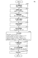
- FIG. 6 is a flowchart for explaining details of the estimation control process of the travelable distance executed by the ECU 300 in the present embodiment.
- the flowchart shown in FIG. 6 is realized by executing a program stored in advance in ECU 300 at a predetermined cycle. Alternatively, for some steps, it is also possible to construct dedicated hardware (electronic circuit) and realize processing.
- ECU 300 integrates vehicle speed VEL at a predetermined time interval in step (hereinafter, step is abbreviated as S) 100 to thereby calculate the travel distance for the predetermined time interval. Calculate.
- ECU 300 calculates power consumption ENG in the predetermined time interval by integrating the product of current IB and voltage VB of power storage device 110 in the predetermined time interval.
- power consumption ENG calculated from current IB and voltage VB of power storage device 110 includes power consumed by auxiliary loads such as an air conditioner and audio, although not shown in FIG. Therefore, in the calculation of the power consumption in the next S120, it is preferable to use the power used only for the vehicle driving force obtained by subtracting the power from the auxiliary load from the power consumption ENG.
- ECU 300 calculates actual power consumption EC_real in S120 based on the travel distance calculated in S100 and the power consumption ENG calculated in S110.
- ECU 300 calculates an average operating point (average vehicle speed Vave and average driving force Fave) at a predetermined time interval (S130), and uses a map as shown in FIG.
- the electricity cost EC_ave is calculated (S140).
- ECU 300 calculates correction coefficient K from actual electricity cost EC_real and reference electricity cost EC_ave.
- ECU 300 executes a smoothing process using individual time constants for correction coefficient K, driving force Facc in the vehicle speed direction, driving force Finc in the gradient direction, average vehicle speed Vave, and inclination signal INC. .
- ECU 300 applies the smoothed operating point to the map as shown in FIG. 2, and calculates predicted power consumption EC_sim.
- ECU 300 obtains predicted travelable distance RMD by calculation based on correction coefficient K (n) after the smoothing process, SOC, total capacity BAT_cap of power storage device 110, and predicted power consumption EC_sim.
- ECU 300 displays the calculated travelable distance RMD on display unit 150 in S190.
- the estimation control when the above estimation control is applied to a hybrid vehicle, when running using the driving force of the engine, or when generating electric power with a motor generator by driving the engine, the actual running distance and The relationship with power consumption may not be properly expressed. Therefore, it is preferable to apply the estimation control for the hybrid vehicle when the engine is not driven.
- the predicted power consumption is calculated while learning (smoothing process) the state of the vehicle that changes every moment in the vehicle that generates the driving force using the power from the power storage device. Based on this, the distance that can be traveled by the remaining capacity of the power storage device can be calculated. As a result, it is possible to reflect the tendency of the driving operation that can vary depending on the user, so that it is possible to calculate more improved power consumption and travelable distance.
- each item is smoothed using individual time constants, while on the one hand suppressing the instability of the operation result and on the other hand improving the follow-up performance against changes.
- it is possible to appropriately reflect the tendency of the driving operation according to the characteristics of each item.
- 100 vehicle 110 power storage device, 111 voltage sensor, 112 current sensor, 115 SMR, 120 PCU, 130 motor generator, 140 drive wheels, 150 display unit, 160 speed sensor, 170 tilt sensor, 180 accelerator pedal, 300 ECU, 310 average Operating point determination unit, 320 actual power consumption calculation unit, 330 standard power consumption calculation unit, 340 correction coefficient calculation unit, 350 smoothing processing unit, 360 travelable distance calculation unit, 370 display control unit, NL1 ground line, PL1 power line.
Abstract
This vehicle (100), which can travel using the electrical power from an incorporated electricity storage device (110), executes: a step (S140) for, in an ECU (300), computing a reference electricity efficiency on the basis of an average operating point determined from the average driving power and the average vehicle velocity for each predetermined time period when travelling by means of the electrical power from the electricity storage device (110); a step (S120) for computing the actual electricity efficiency on the basis of the travelling distance and the amount of power consumption in the time periods; a step (S150, S160, S170) for computing a predicted electricity efficiency by means of smoothing processing on the basis of the reference electricity efficiency and the actual electricity efficiency; and a step (S180) for computing the travelable distance (RMD) that can be traveled by means of the power remaining in the electricity storage device (110) on the basis of the state of charge of the electricity storage device (110) and the predicted electricity efficiency.
Description
本発明は、車両および車両の制御方法に関し、より特定的には、蓄電装置からの電力を用いて走行駆動力を発生する車両における、走行可能距離の推定制御に関する。
The present invention relates to a vehicle and a vehicle control method, and more particularly to estimation control of a travelable distance in a vehicle that generates a travel driving force using electric power from a power storage device.
近年、環境に配慮した車両として、蓄電装置(たとえば二次電池やキャパシタなど)を搭載し、蓄電装置に蓄えられた電力を用いて、モータによって発生する駆動力により走行する車両が注目されている。このような車両には、たとえば電気自動車、ハイブリッド自動車、燃料電池車などが含まれる。
2. Description of the Related Art In recent years, attention has been paid to a vehicle that is mounted with a power storage device (for example, a secondary battery or a capacitor) and travels by driving force generated by a motor using electric power stored in the power storage device as an environment-friendly vehicle. . Such vehicles include, for example, electric vehicles, hybrid vehicles, fuel cell vehicles, and the like.
このような車両においては、しばしば、蓄電装置に残っている電力で走行可能な距離を予測することが必要とされる。ハイブリッド自動車や燃料電池車においては、蓄電装置の電力が使用しつくされた場合でも、エンジンや燃料電池により発電した電力あるいはエンジンからの駆動力で走行が可能である。しかしながら、蓄電装置以外に電力を供給する手段のない電気自動車においては、蓄電装置の電力が使用しつくされた場合には、蓄電装置の充電が行なわれないと走行を継続することができないので、残りの走行可能距離を適切に予測することがさらに重要となる。
In such a vehicle, it is often necessary to predict the distance that can be traveled by the electric power remaining in the power storage device. In a hybrid vehicle and a fuel cell vehicle, even when the electric power of the power storage device is used up, the vehicle can run with the electric power generated by the engine or the fuel cell or the driving force from the engine. However, in an electric vehicle having no means for supplying power other than the power storage device, if the power of the power storage device is used up, it is not possible to continue running unless the power storage device is charged. It is even more important to properly predict the remaining travelable distance.
特開2003-219503号公報(特許文献1)においては、定常経路を定期的に走行する電気自動車において、当該定常経路の前回走行時の電力消費量と航続距離に基づいて、現在残っている蓄電装置の電力で航続可能な距離を算出し、目的地まで走行可能であるか否かを判断する技術が開示される。
In Japanese Patent Application Laid-Open No. 2003-219503 (Patent Document 1), in an electric vehicle that travels regularly on a steady route, the remaining power storage based on the power consumption and cruising distance at the previous travel of the steady route. A technique for calculating a cruising distance with the power of the apparatus and determining whether or not the vehicle can travel to a destination is disclosed.
しかしながら、特開2003-219503号公報(特許文献1)に開示された技術においては、車両を運転するユーザの走り方によっては、同じ走行経路であっても電力消費量が異なる可能性があるので、走行可能距離を前回走行時の情報に基づいて算出しても、その精度は必ずしも高いものとは限らない。
However, in the technique disclosed in Japanese Patent Application Laid-Open No. 2003-219503 (Patent Document 1), the power consumption may be different even on the same travel route depending on how the user who drives the vehicle travels. Even if the travelable distance is calculated based on the information at the time of the previous travel, the accuracy is not necessarily high.
また、異なる走行経路である場合、あるいは、路面状態や交通渋滞などの環境が異なる場合などの場合では、特定の定常経路についての前回走行時の状態に基づいて算出した走行可能距離は、刻々と変化する現在の車両の状態を適切に反映していない可能性がある。
In the case of different driving routes, or when the environment such as road surface conditions or traffic jams are different, the travelable distance calculated based on the state at the time of the previous driving for a specific steady route is It may not properly reflect the changing current vehicle conditions.
本発明は、このような課題を解決するためになされたものであって、その目的は、蓄電装置からの電力を用いて走行駆動力を発生する車両において、蓄電装置の残容量で走行可能な距離を適切に推定することである。
The present invention has been made to solve such problems, and an object of the present invention is to be able to travel with the remaining capacity of the power storage device in a vehicle that generates a driving force using the power from the power storage device. It is to estimate the distance appropriately.
本発明による車両は、回転電機と、制御装置とを備え、搭載した蓄電装置の電力を用いて走行が可能である。回転電機は、蓄電装置からの電力を用いて走行駆動力を発生する。制御装置は、蓄電装置からの電力により走行している際に、予め定められた期間ごとの平均車速および平均駆動力から定まる平均動作点に基づいて第1の電費を演算するとともに、予め定められた期間中における電力消費量および走行距離に基づいて第2の電費を演算し、第1および第2の電費ならびに蓄電装置の充電状態に基づいて、蓄電装置に残存する電力により走行可能な走行可能距離を演算する。
The vehicle according to the present invention includes a rotating electrical machine and a control device, and can travel using the electric power of the installed power storage device. The rotating electrical machine generates traveling driving force using electric power from the power storage device. The control device calculates the first power consumption based on an average operating point determined from an average vehicle speed and an average driving force for each predetermined period when traveling with electric power from the power storage device, and is determined in advance. The second power consumption is calculated based on the power consumption and the travel distance during the period, and the vehicle can travel with the power remaining in the power storage device based on the first and second power costs and the state of charge of the power storage device. Calculate the distance.
好ましくは、制御装置は、第1および第2の電費から修正係数を算出するとともに、修正係数を用いて第1の電費を修正することによって予測電費を演算し、予測電費および蓄電装置の充電状態に基づいて走行可能距離を演算する。
Preferably, the control device calculates a correction coefficient from the first and second power costs, calculates a predicted power cost by correcting the first power cost using the correction coefficient, and calculates the predicted power cost and the state of charge of the power storage device. The travelable distance is calculated based on the above.
好ましくは、修正係数は、第1の電費に対する第2の電費の比率に基づいて算出される。
Preferably, the correction coefficient is calculated based on a ratio of the second power consumption to the first power consumption.
好ましくは、制御装置は、予め定められた時定数を用いて平均動作点を時間軸方向に平滑化するように修正した動作点に基づいて、予測電費を演算する。
Preferably, the control device calculates the predicted power consumption based on the operating point that has been corrected so as to smooth the average operating point in the time axis direction using a predetermined time constant.
好ましくは、制御装置は、平滑化において、平均車速および平均駆動力を、異なる時定数を用いて平滑化する。
Preferably, in the smoothing, the control device smoothes the average vehicle speed and the average driving force using different time constants.
好ましくは、平均車速についての時定数は、平均駆動力についての時定数よりも小さい。
Preferably, the time constant for the average vehicle speed is smaller than the time constant for the average driving force.
好ましくは、制御装置は、平均車速についての平滑化において、走行駆動力のうちの路面勾配から必要とされる駆動力と残余の駆動力とで異なる時定数を用いて平滑化する。
Preferably, the control device smoothes the average vehicle speed using different time constants for the driving force required from the road surface gradient of the driving force and the remaining driving force.
好ましくは、回転電機は、駆動輪に結合されるとともに、駆動輪の回転力によって発電することが可能である。制御装置は、走行距離のうち、回転電機による発電電力がしきい値を下回る状態で走行した距離に基づいて、第2の電費を演算する。
Preferably, the rotating electrical machine is coupled to the drive wheel and can generate power by the rotational force of the drive wheel. The control device calculates the second power consumption based on the distance traveled in a state where the power generated by the rotating electrical machine is below the threshold value among the travel distance.
好ましくは、車両はエンジンをさらに備える。走行駆動力は、回転電機からの駆動力とエンジンからの駆動力とを用いて出力される。制御装置は、エンジンが非駆動状態の場合に、走行可能距離の演算を実行する。
Preferably, the vehicle further includes an engine. The traveling driving force is output using the driving force from the rotating electrical machine and the driving force from the engine. The control device calculates a travelable distance when the engine is in a non-driving state.
好ましくは、車両は、走行可能距離をユーザに通知するための表示部をさらに備える。
本発明による車両の制御方法は、搭載した蓄電装置の電力を用いて走行が可能な車両についての制御方法である。車両は、蓄電装置からの電力を用いて走行駆動力を発生するための回転電機を含む。制御方法は、蓄電装置からの電力により走行している際に、予め定められた期間ごとの平均車速および平均駆動力から定まる平均動作点に基づいて第1の電費を演算するステップと、予め定められた期間中における電力消費量および走行距離に基づいて第2の電費を演算するステップと、第1および第2の電費ならびに蓄電装置の充電状態に基づいて、蓄電装置に残存する電力により走行可能な走行可能距離を演算するステップとを備える。 Preferably, the vehicle further includes a display unit for notifying the user of the travelable distance.
The vehicle control method according to the present invention is a control method for a vehicle that can travel using the electric power of the installed power storage device. The vehicle includes a rotating electrical machine for generating travel driving force using electric power from the power storage device. The control method includes a step of calculating a first power consumption based on an average operating point determined from an average vehicle speed and an average driving force for each predetermined period when traveling with electric power from the power storage device; The second power consumption is calculated based on the power consumption and the travel distance during the specified period, and the vehicle can travel with the power remaining in the power storage device based on the first and second power costs and the charge state of the power storage device. Calculating a possible travel distance.
本発明によれば、蓄電装置からの電力を用いて走行駆動力を発生する車両において、蓄電装置の残容量で走行可能な距離を適切に推定することができる。
According to the present invention, it is possible to appropriately estimate the distance that can be traveled by the remaining capacity of the power storage device in the vehicle that generates the driving force using the power from the power storage device.
以下、本発明の実施の形態について、図面を参照しながら詳細に説明する。なお、図中同一または相当部分には同一符号を付してその説明は繰り返さない。
Hereinafter, embodiments of the present invention will be described in detail with reference to the drawings. In the drawings, the same or corresponding parts are denoted by the same reference numerals and description thereof will not be repeated.
図1は、本実施の形態に従う車両100の全体ブロック図である。図1を参照して、車両100は、蓄電装置110と、電圧センサ111と、電流センサ112と、システムメインリレー(System Main Relay:SMR)115と、駆動装置であるPCU(Power Control Unit)120と、モータジェネレータ130と、駆動輪140と、表示部150と、速度センサ160と、傾斜センサ170と、制御装置であるECU(Electronic Control Unit)300とを備える。
FIG. 1 is an overall block diagram of vehicle 100 according to the present embodiment. Referring to FIG. 1, vehicle 100 includes a power storage device 110, a voltage sensor 111, a current sensor 112, a system main relay (SMR) 115, and a PCU (Power Control Unit) 120 that is a driving device. A motor generator 130, drive wheels 140, a display unit 150, a speed sensor 160, an inclination sensor 170, and an ECU (Electronic Control Unit) 300 that is a control device.
蓄電装置110は、充放電可能に構成された電力貯蔵要素である。蓄電装置110は、たとえば、リチウムイオン電池、ニッケル水素電池または鉛蓄電池などの二次電池、あるいは電気二重層キャパシタなどの蓄電素子を含んで構成される。
The power storage device 110 is a power storage element configured to be chargeable / dischargeable. The power storage device 110 includes, for example, a secondary battery such as a lithium ion battery, a nickel hydride battery, or a lead storage battery, or a power storage element such as an electric double layer capacitor.
蓄電装置110は、電力線PL1および接地線NL1を介してPCU120に接続される。そして、蓄電装置110は、車両100の駆動力を発生させるための電力をPCU120に供給する。また、蓄電装置110は、モータジェネレータ130で発電された電力を蓄電する。蓄電装置110の出力はたとえば200V程度である。
The power storage device 110 is connected to the PCU 120 via the power line PL1 and the ground line NL1. Then, power storage device 110 supplies power for generating driving force of vehicle 100 to PCU 120. The power storage device 110 stores the electric power generated by the motor generator 130. The output of power storage device 110 is, for example, about 200V.
電圧センサ111は、蓄電装置110の電圧VBを検出し、その検出結果をECU300へ出力する。電流センサ112は、蓄電装置に入出力される電流IBを検出し、その検出値をECU300へ出力する。
Voltage sensor 111 detects voltage VB of power storage device 110 and outputs the detection result to ECU 300. Current sensor 112 detects current IB input to and output from the power storage device, and outputs the detected value to ECU 300.
SMR115に含まれるリレーは、蓄電装置110とPCU120とを結ぶ電力線PL1および接地線NL1にそれぞれ介挿される。そして、SMR115は、ECU300からの制御信号SE1に基づいて、蓄電装置110とPCU120との間での電力の供給と遮断とを切替える。
The relays included in the SMR 115 are inserted into the power line PL1 and the ground line NL1 that connect the power storage device 110 and the PCU 120, respectively. SMR 115 switches between power supply and cutoff between power storage device 110 and PCU 120 based on control signal SE <b> 1 from ECU 300.
PCU120は、いずれも図示しないが、コンバータ、インバータなどが含まれる。コンバータは、ECU300からの制御信号PWCにより制御されて蓄電装置110からの電圧を変換する。インバータは、ECU300からの制御信号PWIにより制御されて、コンバータで変換された電力を用いてモータジェネレータ130を駆動する。
The PCU 120 includes a converter, an inverter, etc., although none are shown. The converter is controlled by a control signal PWC from ECU 300 to convert the voltage from power storage device 110. The inverter is controlled by a control signal PWI from ECU 300 and drives motor generator 130 using electric power converted by the converter.
モータジェネレータ130は交流回転電機であり、たとえば、永久磁石が埋設されたロータを備える永久磁石型同期電動機である。
The motor generator 130 is an AC rotating electric machine, for example, a permanent magnet type synchronous motor including a rotor in which a permanent magnet is embedded.
モータジェネレータ130の出力トルクは、駆動輪140に伝達されて、車両100を走行させる。モータジェネレータ130は、車両100の回生制動動作時には、駆動輪140の回転力によって発電することができる。そして、その発電電力は、PCU120によって蓄電装置110の充電電力に変換される。
The output torque of the motor generator 130 is transmitted to the drive wheels 140 to cause the vehicle 100 to travel. The motor generator 130 can generate electric power by the rotational force of the drive wheels 140 during the regenerative braking operation of the vehicle 100. Then, the generated power is converted into charging power for power storage device 110 by PCU 120.
また、モータジェネレータ130の他にエンジン(図示せず)が搭載されたハイブリッド自動車では、このエンジンおよびモータジェネレータ130を協調的に動作させることによって、必要な車両駆動力が発生される。この場合、エンジンの回転による発電電力を用いて、蓄電装置110を充電することも可能である。
Further, in a hybrid vehicle equipped with an engine (not shown) in addition to the motor generator 130, a necessary vehicle driving force is generated by operating the engine and the motor generator 130 in a coordinated manner. In this case, it is also possible to charge the power storage device 110 using the power generated by the rotation of the engine.
すなわち、本実施の形態における車両100は、車両駆動力を発生するための電動機を搭載する車両を示すものであり、エンジンおよび電動機により車両駆動力を発生するハイブリッド自動車、エンジンを搭載しない電気自動車および燃料電池自動車などを含む。
In other words, vehicle 100 in the present embodiment represents a vehicle equipped with an electric motor for generating vehicle driving force, and is a hybrid vehicle that generates vehicle driving force by an engine and an electric motor, an electric vehicle that is not equipped with an engine, and Includes fuel cell vehicles.
表示部150は、ECU300からの制御信号DSPに基づいて、ユーザに対して各種の情報を表示する。
Display unit 150 displays various types of information to the user based on control signal DSP from ECU 300.
速度センサ160は、車両100の車速に関する信号VELを検出しECU300へ出力する。速度センサ160は、たとえば、モータジェネレータ130の回転角を検出するための回転角センサであってもよいし、駆動輪140の回転速度を検出するための速度センサであってもよい。
The speed sensor 160 detects a signal VEL related to the vehicle speed of the vehicle 100 and outputs it to the ECU 300. Speed sensor 160 may be, for example, a rotation angle sensor for detecting the rotation angle of motor generator 130, or may be a speed sensor for detecting the rotation speed of drive wheel 140.
傾斜センサ170は、車両100が坂路を走行している場合の、路面の傾斜を検出するためのセンサであり、たとえば、加速度センサなどが含まれる。傾斜センサ170は、検出した路面の傾斜を示す傾斜信号INCをECU300へ出力する。
The inclination sensor 170 is a sensor for detecting the inclination of the road surface when the vehicle 100 is traveling on a slope, and includes, for example, an acceleration sensor. Inclination sensor 170 outputs an inclination signal INC indicating the detected inclination of the road surface to ECU 300.
ECU300は、いずれも図1には図示しないがCPU(Central Processing Unit)、記憶装置および入出力バッファを含み、各センサ等からの信号の入力や各機器への制御信号の出力を行なうとともに、車両100および各機器の制御を行なう。なお、これらの制御については、ソフトウェアによる処理に限られず、専用のハードウェア(電子回路)で処理することも可能である。
ECU 300 includes a CPU (Central Processing Unit), a storage device, and an input / output buffer (not shown in FIG. 1). The ECU 300 inputs a signal from each sensor and outputs a control signal to each device. 100 and each device are controlled. Note that these controls are not limited to processing by software, and can be processed by dedicated hardware (electronic circuit).
ECU300は、電圧センサ111および電流センサ112から、蓄電装置110の電圧VBおよび電流IBの検出値を受ける。ECU300は、電圧VBおよび電流IBに基づいて、蓄電装置110の充電状態(以下、SOC(State of Charge)とも称する。)を演算する。
ECU 300 receives detection values of voltage VB and current IB of power storage device 110 from voltage sensor 111 and current sensor 112. ECU 300 calculates the state of charge of power storage device 110 (hereinafter also referred to as SOC (State of Charge)) based on voltage VB and current IB.
また、ECU300は、アクセルペダル180の操作量を示す信号ACCを受ける。ECU300は、アクセルペダル180の操作量ACCに基づいて、ユーザから要求される車両駆動力を算出する。
ECU 300 also receives a signal ACC indicating the amount of operation of accelerator pedal 180. ECU 300 calculates the vehicle driving force requested by the user based on the operation amount ACC of accelerator pedal 180.
上記のような車両100における蓄電装置110の充電は、エンジンにより走行する車両における燃料補給のように短時間では完了せず、比較的長い時間が必要となる。
The charging of the power storage device 110 in the vehicle 100 as described above is not completed in a short time as in the case of refueling in a vehicle traveling by an engine, and a relatively long time is required.
そのため、現在残っている蓄電装置の容量で、あとどれくらい走行できるのかを知ることが、ユーザにとっては重要である。
Therefore, it is important for the user to know how much he can drive with the capacity of the remaining power storage device.
図2は、車両100における、車速、駆動力および電費の関係を説明するための図である。図2においては、横軸に車速VELが示され、縦軸には駆動力FRCが示される。図2中の曲線W10は、各車速VELにおいて出力可能な最大駆動力を示す。また、図2中の曲線W11~W15は、単位走行距離あたりに消費される電力量、いわゆる電費(Wh/km)を示しており、一般的に電費が小さいほうがエネルギ効率がよいことを意味する。
FIG. 2 is a diagram for explaining the relationship among the vehicle speed, driving force, and power consumption in the vehicle 100. In FIG. 2, the vehicle speed VEL is shown on the horizontal axis, and the driving force FRC is shown on the vertical axis. A curve W10 in FIG. 2 indicates the maximum driving force that can be output at each vehicle speed VEL. Curves W11 to W15 in FIG. 2 indicate the amount of power consumed per unit travel distance, so-called power consumption (Wh / km), and generally means that energy efficiency is better when power consumption is smaller. .
図2を参照して、図1に示した車両100のような電気自動車、あるいはハイブリッド車両においてエンジンを停止して蓄電装置からの電力のみで走行するような場合は、定常走行における電費は、ある時間間隔における平均車速Vaveおよび平均駆動力Faveで定まる動作点(たとえば、図2中の点P10)によりほぼ一意に決まることが知られている。
Referring to FIG. 2, in an electric vehicle such as vehicle 100 shown in FIG. 1 or in a hybrid vehicle, when the engine is stopped and the vehicle travels only with the electric power from the power storage device, there is a power consumption in steady traveling. It is known that it is determined almost uniquely by an operating point (for example, point P10 in FIG. 2) determined by the average vehicle speed Vave and the average driving force Fave in the time interval.
しかしながら、特定の時間間隔における平均車速Vaveおよび平均駆動力Faveが同じであっても、たとえば、ほぼ一定速度で走行する場合と、加速および減速を頻繁に繰り返しながら走行する場合とでは、電力消費量は変化し得る。また、平地を走行する場合と、山道などの勾配のある路面を走行する場合とでも、電力消費量は変化し得る。
However, even when the average vehicle speed Vave and the average driving force Fave at the specific time interval are the same, for example, when the vehicle travels at a substantially constant speed and when the vehicle travels while frequently repeating acceleration and deceleration, Can change. Also, the power consumption can vary between when traveling on a flat ground and when traveling on a sloped road surface such as a mountain road.
そのため、平均車速Vaveおよび平均駆動力Faveで定まる動作点から決定される電費を用いて、蓄電装置の残容量による走行可能距離を算出した場合、算出された走行可能距離は、ユーザの運転の仕方(いわゆる、癖)や路面状況が適切に反映されていないために、信頼性に欠けるものとなってしまう可能性がある。
Therefore, when the travelable distance based on the remaining capacity of the power storage device is calculated using the power consumption determined from the operating point determined by the average vehicle speed Vave and the average driving force Fave, the calculated travelable distance is determined by the user's driving method. Since the road surface condition (so-called soot) is not properly reflected, it may become unreliable.
特に、蓄電装置に蓄えられた電力のみを用いて走行する電気自動車においては、走行中に蓄電装置の電力を使い果たしてしまった場合には、もはや自走することが不可能となってしまうので、エンジンなどの他の駆動機構や発電機構を有するハイブリッド車両や燃料電池者などに比べて、蓄電装置の残容量による走行可能距離を正しくユーザに通知することがより重要となる。
In particular, in an electric vehicle that travels using only the power stored in the power storage device, if the power of the power storage device is exhausted while traveling, it will no longer be able to self-run, It is more important to correctly notify the user of the travelable distance due to the remaining capacity of the power storage device, compared to a hybrid vehicle having another drive mechanism such as an engine or a power generation mechanism, or a fuel cell operator.
そこで、本実施の形態においては、図2で示したような予め定められた標準的なマップを用いて、ある時間間隔における平均車速Vaveおよび平均駆動力Faveで定まる動作点から決定される基準電費と、その時間間隔における実際の走行距離および実際の電力消費量から決定される実電費とを比較し、これらの違いに基づいて算出された予測電費を用いて残りの走行可能距離を算出する、走行可能距離の推定制御を実行する。
Therefore, in the present embodiment, a standard power consumption determined from an operating point determined by average vehicle speed Vave and average driving force Fave at a certain time interval using a predetermined standard map as shown in FIG. And the actual travel distance in that time interval and the actual power consumption determined from the actual power consumption, and calculate the remaining travelable distance using the predicted power consumption calculated based on these differences, The estimation control of the travelable distance is executed.
具体的には、基準電費に対する実電費の比率(=実電費/基準電費)を修正係数として演算し、その修正係数を用いて、図2で示した標準的なマップの電費を補正することによって、ユーザの運転の仕方や路面状況による影響を電費に反映する。
Specifically, the ratio of the actual electricity cost to the reference electricity cost (= actual electricity cost / reference electricity cost) is calculated as a correction factor, and the electricity cost of the standard map shown in FIG. 2 is corrected using the correction factor. The influence of the user's driving method and the road surface condition is reflected in the electricity cost.
なお、このとき、演算された修正係数をそのまま直接反映すると、短期間に電費の急激な増減が頻繁に繰り返されてしまう場合があり、それに伴って走行可能距離が頻繁に変化するので、かえって推定された走行可能距離の信頼性が低下するおそれがある。
At this time, if the calculated correction coefficient is directly reflected as it is, the rapid increase / decrease in power consumption may frequently be repeated in a short period of time, and the travelable distance frequently changes accordingly. There is a risk that the reliability of the traveled distance will be reduced.
そのため、本実施の形態においては、修正係数を反映する際、修正係数による変化を時間的に平滑化して緩やかに変化させる平滑化処理、いわゆる学習処理をさらに適用する。これによって、ユーザの運転の仕方や路面状況による影響を反映しつつ、修正係数の急激な変化を抑制して走行可能距離の推定値の信頼性が低下することを防止できる。
Therefore, in the present embodiment, when the correction coefficient is reflected, a smoothing process in which a change due to the correction coefficient is temporally smoothed and gradually changed, that is, a so-called learning process is further applied. Accordingly, it is possible to prevent the reliability of the estimated value of the travelable distance from being lowered by suppressing the rapid change of the correction coefficient while reflecting the influence of the user's driving method and the road surface condition.
さらに、図2のマップを用いて基準電費を演算する場合に、平均車速Vaveおよび平均駆動力Faveによる平均動作点を設定することが必要であるが、たとえば、高速道路から一般道に移行した場合や、平地から山道に移行した場合には、この平均動作点が急激に変化することが考えられる。そのため、このような平均動作点の急激な変化によって、図2のマップから得られる基準電費の値が急激に変化してしまう可能性があるので、平均車速Vaveおよび平均駆動力Faveによる平均動作点の設定においても、上記の修正係数と同様に平滑化処理を行なうことが好ましい。
Furthermore, when calculating the reference electricity cost using the map of FIG. 2, it is necessary to set an average operating point based on the average vehicle speed Vave and average driving force Fave. For example, when moving from a highway to a general road In addition, when moving from a flat land to a mountain road, this average operating point may change rapidly. Therefore, there is a possibility that the value of the reference electricity cost obtained from the map of FIG. 2 may change suddenly due to such a rapid change in the average operating point. Therefore, the average operating point based on the average vehicle speed Vave and the average driving force Fave In this setting, it is preferable to perform the smoothing process in the same manner as the correction coefficient.
このとき、駆動力については、以下の図3および図4で説明されるように、駆動力の用途によって平滑化の度合い、すなわち時定数を変化させる。
At this time, with respect to the driving force, as will be described with reference to FIGS. 3 and 4 below, the degree of smoothing, that is, the time constant is changed depending on the use of the driving force.
図3は、路面勾配と駆動力との関係を説明するための第1の図である。図3を参照して、車両100が傾斜角θの坂路にある状態において、車両100の質量をmで表わし重力加速度をgで表わすと、車両100にかかる重力の斜面に沿った成分に対抗するために必要となる駆動力Fincは、以下の式(1)で表わすことができる。
FIG. 3 is a first diagram for explaining the relationship between the road surface gradient and the driving force. Referring to FIG. 3, when vehicle 100 is on a slope with an inclination angle θ, the mass of vehicle 100 is represented by m and the acceleration of gravity is represented by g, which counters components along the slope of gravity applied to vehicle 100. The driving force Finc required for this can be expressed by the following equation (1).
Finc=mg・sinθ … (1)
この駆動力Fincは、傾斜角θが大きくなるにつれて増加する。 Finc = mg · sin θ (1)
This driving force Finc increases as the inclination angle θ increases.
この駆動力Fincは、傾斜角θが大きくなるにつれて増加する。 Finc = mg · sin θ (1)
This driving force Finc increases as the inclination angle θ increases.
また、車両100の走行方向に加速するため、および速度を維持するために必要となる駆動力をFaccとすると、車両100が出力すべきトータル駆動力Ftotalは、以下の式(2)のように表わせる。
Further, if the driving force necessary for accelerating the vehicle 100 in the traveling direction and maintaining the speed is Facc, the total driving force Ftotal to be output by the vehicle 100 is expressed by the following equation (2). I can express.
Ftotal=Finc+Facc … (2)
図4は、図2のようなマップにおける、平均動作点の変化と駆動力を説明するための図である。図4において、曲線W21~W24は、それぞれ、一定の路面勾配において必要とされる車速VELおよび駆動力FRCを示す。 Ftotal = Finc + Facc (2)
FIG. 4 is a diagram for explaining the change of the average operating point and the driving force in the map as shown in FIG. In FIG. 4, curves W21 to W24 indicate the vehicle speed VEL and the driving force FRC required for a constant road surface gradient, respectively.
図4を参照して、今、平均動作点が、平地を示す動作点P22から点P20に変化した場合を考える。この場合は、車速VELはほぼ一定であり、駆動力FRCのみが増加した例である。
Referring to FIG. 4, let us consider a case where the average operating point is changed from an operating point P22 indicating a flat ground to a point P20. In this case, the vehicle speed VEL is substantially constant, and only the driving force FRC is increased.
ここで、当該時間間隔における平均の路面勾配が破線の曲線W24であった場合、点P22から点P20へ変化した駆動力のうち、点P22から曲線W24上の点P21までの駆動力が、路面勾配によって生じる重力に対抗するために必要となる駆動力Fincであり、残余の駆動力(点P21から点P22まで)が加速および速度維持のために必要となる駆動力Faccに相当する。
Here, when the average road surface gradient in the time interval is a dashed curve W24, the driving force from the point P22 to the point P21 on the curve W24 among the driving force changed from the point P22 to the point P20 is the road surface. This is the driving force Finc required to counter the gravity caused by the gradient, and the remaining driving force (from point P21 to point P22) corresponds to the driving force Facc required for acceleration and speed maintenance.
このとき、加速および速度維持のために必要となる駆動力Faccは、動作点を求める時間間隔においては、走行を維持するために比較的長い期間継続される。一方で、路面勾配によって生じる重力に対抗するために必要となる駆動力Fincは、坂路が長距離にわたって続いている場合は別として、通常は駆動力Faccに比べると比較的短い時間だけ出力される。
At this time, the driving force Facc required for acceleration and speed maintenance is continued for a relatively long period in order to maintain traveling in the time interval for obtaining the operating point. On the other hand, the driving force Finc necessary to counter the gravity caused by the road surface gradient is usually output for a relatively short time compared to the driving force Facc, except when the slope continues for a long distance. .
そのため、駆動力Fincについての時定数を小さく設定した場合は、比較的短時間な変化に対して動作点が過敏に追従してしまうことになる。したがって、路面勾配に対する駆動力Fincについては、車速に対する駆動力Faccに比べて時定数が大きくなるように設定し、より緩やかに変化させることで、走行可能距離の推定値の安定性が向上し、より一層、走行可能距離の推定値の信頼性を高めることが可能となる。すなわち、ユーザの運転操作についての癖との関連性が高い車速に対する駆動力Faccが演算結果に反映されやすいので、ユーザの癖を考慮して平均動作点を演算することが可能となる。
Therefore, when the time constant for the driving force Finc is set to a small value, the operating point will follow the change with a relatively short time. Accordingly, the driving force Finc for the road surface gradient is set so that the time constant is larger than the driving force Facc for the vehicle speed, and by changing more slowly, the stability of the estimated value of the travelable distance is improved. Further, the reliability of the estimated value of the travelable distance can be improved. That is, since the driving force Facc with respect to the vehicle speed having a high relevance to the user's driving operation is easily reflected in the calculation result, the average operating point can be calculated in consideration of the user's driving force.
図5は、本実施の形態において、ECU300で実行される走行可能距離の推定制御を説明するための機能ブロック図である。図5の機能ブロック図に記載された各機能ブロックは、ECU300によるハードウェア的あるいはソフトウェア的な処理によって実現される。
FIG. 5 is a functional block diagram for explaining the estimation control of the travelable distance executed by the ECU 300 in the present embodiment. Each functional block described in the functional block diagram of FIG. 5 is realized by hardware or software processing by ECU 300.
図1および図5を参照して、ECU300は、平均動作点決定部310と、実電費演算部320と、基準電費演算部330と、修正係数演算部340と、平滑化処理部350と、走行可能距離演算部360と、表示制御部370とを含む。
Referring to FIGS. 1 and 5, ECU 300 includes an average operating point determination unit 310, an actual electricity cost calculation unit 320, a reference electricity cost calculation unit 330, a correction coefficient calculation unit 340, a smoothing processing unit 350, a running A possible distance calculation unit 360 and a display control unit 370 are included.
平均動作点決定部310は、アクセルペダル180の操作量ACCと、速度センサ160からの車速VELとを受ける。アクセルペダル180の操作量ACCに基づいて、所定の時間間隔における平均駆動力Faveを算出するとともに、その所定の時間間隔における平均車速Vaveを車速VELから算出する。そして、平均動作点決定部310は、演算した平均車速Vaveおよび平均駆動力Faveを、基準電費演算部330および平滑化処理部350へ出力する。
The average operating point determination unit 310 receives the operation amount ACC of the accelerator pedal 180 and the vehicle speed VEL from the speed sensor 160. Based on the operation amount ACC of the accelerator pedal 180, the average driving force Fave at a predetermined time interval is calculated, and the average vehicle speed Vave at the predetermined time interval is calculated from the vehicle speed VEL. Then, the average operating point determination unit 310 outputs the calculated average vehicle speed Vave and average driving force Fave to the reference power consumption calculation unit 330 and the smoothing processing unit 350.
基準電費演算部330は、平均動作点決定部310からの平均車速Vaveおよび平均駆動力Faveを受ける。基準電費演算部330は、図2で示したような、予め定められたマップを用いて、平均車速Vaveおよび平均駆動力Faveに基づいて、標準的な状態における基準電費EC_aveを演算する。そして、基準電費演算部330は、演算された基準電費EC_aveを修正係数演算部340へ出力する。
The reference power consumption calculation unit 330 receives the average vehicle speed Vave and the average driving force Fave from the average operating point determination unit 310. The reference power consumption calculation unit 330 calculates a reference power consumption EC_ave in a standard state based on the average vehicle speed Vave and the average driving force Fave using a predetermined map as shown in FIG. Then, the reference power consumption calculation unit 330 outputs the calculated reference power consumption EC_ave to the correction coefficient calculation unit 340.
実電費演算部320は、蓄電装置110の電圧VB,電流IB、および、車速VELを受ける。実電費演算部320は、これらの情報に基づいて、上記の所定の時間間隔における実電費EC_realを演算する。そして、実電費演算部320は、演算した実電費EC_realを修正係数演算部340へ出力する。
Actual power consumption calculation unit 320 receives voltage VB, current IB, and vehicle speed VEL of power storage device 110. Based on these pieces of information, the actual electricity cost calculation unit 320 calculates the actual electricity cost EC_real at the predetermined time interval. Then, the actual power consumption calculation unit 320 outputs the calculated actual power consumption EC_real to the correction coefficient calculation unit 340.
修正係数演算部340は、基準電費演算部330からの基準電費EC_aveおよび実電費演算部320からの実電費EC_realを受ける。修正係数演算部340は、これらの情報に基づいて、図2のようなマップに、基準電費EC_aveと実電費EC_realとの違いを反映させるための修正係数Kを演算し、平滑化処理部350に出力する。なお、修正係数Kは、一例としては、式(3)に示されるように、基準電費EC_aveに対する実電費EC_realの比率として定義され得る。
The correction coefficient calculation unit 340 receives the reference electricity cost EC_ave from the reference electricity cost calculation unit 330 and the actual electricity cost EC_real from the actual electricity cost calculation unit 320. Based on this information, the correction coefficient calculation unit 340 calculates a correction coefficient K for reflecting the difference between the standard power consumption EC_ave and the actual power consumption EC_real in the map as shown in FIG. Output. As an example, the correction coefficient K can be defined as the ratio of the actual electricity cost EC_real to the reference electricity cost EC_ave, as shown in Expression (3).
K=EC_real/EC_ave … (3)
平滑化処理部350は、修正係数演算部340からの修正係数K、平均動作点決定部310からの平均車速Vaveおよび平均駆動力Fave、ならびに、傾斜センサ170からの傾斜信号INCを受ける。平滑化処理部350においては、これらの情報について、前回の演算結果から今回の演算値への変化が急激にならないような平滑化処理を実行する。たとえば、修正係数Kについては、前回の演算結果をK(n-1)、今回の演算値をK、そして、平滑化後の演算結果をK(n)とすると、時定数αを用いて、式(4)のように演算され得る。 K = EC_real / EC_ave (3)
Smoothing processing unit 350 receives correction coefficient K from correction coefficient calculation unit 340, average vehicle speed Vave and average driving force Fave from average operating point determination unit 310, and inclination signal INC from inclination sensor 170. The smoothing processing unit 350 performs a smoothing process on these pieces of information so that the change from the previous calculation result to the current calculation value does not become abrupt. For example, for the correction coefficient K, if the previous calculation result is K (n−1), the current calculation value is K, and the calculation result after smoothing is K (n), the time constant α is used. It can be calculated as in equation (4).
平滑化処理部350は、修正係数演算部340からの修正係数K、平均動作点決定部310からの平均車速Vaveおよび平均駆動力Fave、ならびに、傾斜センサ170からの傾斜信号INCを受ける。平滑化処理部350においては、これらの情報について、前回の演算結果から今回の演算値への変化が急激にならないような平滑化処理を実行する。たとえば、修正係数Kについては、前回の演算結果をK(n-1)、今回の演算値をK、そして、平滑化後の演算結果をK(n)とすると、時定数αを用いて、式(4)のように演算され得る。 K = EC_real / EC_ave (3)
K(n)=K(n-1)+α{K-K(n-1)} … (4)
ここで、0<α<1である。 K (n) = K (n−1) + α {KK (n−1)} (4)
Here, 0 <α <1.
ここで、0<α<1である。 K (n) = K (n−1) + α {KK (n−1)} (4)
Here, 0 <α <1.
言い換えれば、平滑化処理部350は、修正係数K、平均車速Vave、平均駆動力Faveおよび傾斜信号INCについての学習演算を実行する。この際、各項目についての時定数は、個別に設定することが可能である。これらの時定数の各々は、他と同じ値としてもよいし、他と異なる値としてもよい。
In other words, the smoothing processing unit 350 executes a learning calculation for the correction coefficient K, the average vehicle speed Vave, the average driving force Fave, and the tilt signal INC. At this time, the time constant for each item can be set individually. Each of these time constants may be the same value as the others, or may be different from the others.
なお、平均駆動力Faveについては、図3および図4で説明したように、路面の傾斜によって作用する重力に対抗するための駆動力Fincと、加速および車速維持のための駆動力Faccとに分解することができ、これらの各々について異なる時定数により平滑化することが好ましい。これは、勾配方向の駆動力Fincについては、車速方向の駆動力Faccに比べて相対的に短時間に(すなわち、急激に)増減する傾向があるので、その変化を演算結果に直ちに反映させると、演算結果が頻繁に増減を繰り返し不安定になるおそれがある。すなわち、ユーザの運転操作についての癖との関連性が高い車速に対する駆動力Faccが演算結果に反映されやすいので、駆動力Fincは駆動力Faccにくらべてより緩やかな変化となるように時定数を設定することで、ユーザの癖を考慮して平均動作点を演算することが可能となる。
Note that the average driving force Fave is decomposed into a driving force Finc for combating gravity acting by road surface inclination and a driving force Facc for accelerating and maintaining the vehicle speed, as described with reference to FIGS. 3 and 4. Preferably, each of these is smoothed with a different time constant. This is because the driving force Finc in the gradient direction tends to increase or decrease in a relatively short time (that is, abruptly) as compared with the driving force Facc in the vehicle speed direction. There is a risk that the calculation result will frequently become unstable by repeatedly increasing and decreasing. That is, since the driving force Facc with respect to the vehicle speed, which has a high relevance to the user's driving behavior, is easily reflected in the calculation result, the time constant is set so that the driving force Finc changes more slowly than the driving force Facc. By setting, it is possible to calculate the average operating point in consideration of the user's habit.
平滑化処理部350は、上述のようにして得られた演算結果K(n),Facc(n),Finc(n),Vave(n),INC(n)を、走行可能距離演算部360へ出力する。
The smoothing processing unit 350 sends the calculation results K (n), Facc (n), Finc (n), Vave (n), INC (n) obtained as described above to the travelable distance calculation unit 360. Output.
走行可能距離演算部360は、平滑化処理部350の演算結果と、蓄電装置110のSOCとを受ける。走行可能距離演算部360は、平滑化処理部350の演算結果に基づいて求めた平滑化処理後の動作点を定める。そして、走行可能距離演算部360は、図2で示したようなマップから当該動作点についての電費を演算するとともに、これにユーザの特性を示す修正係数K(n)を掛け合わせることよって予測電費を推定する。その後、走行可能距離演算部360は、推定された予測電費とSOCに基づいて、蓄電装置110の残容量による走行可能距離RMDを演算し、表示制御部370へ出力する。
Travelable distance calculation unit 360 receives the calculation result of smoothing processing unit 350 and the SOC of power storage device 110. The travelable distance calculation unit 360 determines an operating point after the smoothing process obtained based on the calculation result of the smoothing processing unit 350. Then, the travelable distance calculation unit 360 calculates the power consumption for the operating point from the map as shown in FIG. 2, and multiplies this by the correction coefficient K (n) indicating the user's characteristics, thereby predicting the power consumption. Is estimated. Thereafter, travelable distance calculation unit 360 calculates travelable distance RMD based on the remaining capacity of power storage device 110 based on the estimated predicted power consumption and SOC, and outputs the calculated travelable distance RMD to display control unit 370.
表示制御部370は、走行可能距離演算部360からの走行可能距離RMDを受け、制御信号DSPにより、その走行可能距離RMDの値を表示部150に表示させる。
The display control unit 370 receives the travelable distance RMD from the travelable distance calculation unit 360 and causes the display unit 150 to display the value of the travelable distance RMD by the control signal DSP.
図6は、本実施の形態において、ECU300で実行される走行可能距離の推定制御処理の詳細を説明するためのフローチャートである。図6に示すフローチャートは、ECU300に予め格納されたプログラムを所定周期で実行することによって実現される。あるいは、一部のステップについては、専用のハードウェア(電子回路)を構築して処理を実現することも可能である。
FIG. 6 is a flowchart for explaining details of the estimation control process of the travelable distance executed by the ECU 300 in the present embodiment. The flowchart shown in FIG. 6 is realized by executing a program stored in advance in ECU 300 at a predetermined cycle. Alternatively, for some steps, it is also possible to construct dedicated hardware (electronic circuit) and realize processing.
図1および図6を参照して、ECU300は、ステップ(以下、ステップをSと略す。)100にて、所定の時間間隔における車速VELを積算することによって、所定の時間間隔についての走行距離を演算する。
Referring to FIGS. 1 and 6, ECU 300 integrates vehicle speed VEL at a predetermined time interval in step (hereinafter, step is abbreviated as S) 100 to thereby calculate the travel distance for the predetermined time interval. Calculate.
さらに、ECU300は、当該所定の時間間隔において、蓄電装置110の電流IBおよび電圧VBの積を積算することによって、所定の時間間隔における消費電力ENGを演算する。なお、蓄電装置110の電流IBおよび電圧VBから算出される消費電力ENGにはは、図1には示していないが、エアコンやオーディオなどの補機負荷によって消費される電力も含まれている。そのため、次のS120における電費の演算においては、上記の消費電力ENGからこれら補機負荷による電力を差し引いた、車両駆動力のみに用いられる電力を用いることが好適である。
Further, ECU 300 calculates power consumption ENG in the predetermined time interval by integrating the product of current IB and voltage VB of power storage device 110 in the predetermined time interval. Note that power consumption ENG calculated from current IB and voltage VB of power storage device 110 includes power consumed by auxiliary loads such as an air conditioner and audio, although not shown in FIG. Therefore, in the calculation of the power consumption in the next S120, it is preferable to use the power used only for the vehicle driving force obtained by subtracting the power from the auxiliary load from the power consumption ENG.
ECU300は、S120にて、S100で算出した走行距離とS110で算出した消費電力ENGに基づいて、実電費EC_realを算出する。
ECU 300 calculates actual power consumption EC_real in S120 based on the travel distance calculated in S100 and the power consumption ENG calculated in S110.
次に、ECU300は、所定の時間間隔における平均動作点(平均車速Vaveおよび平均駆動力Fave)を算出するとともに(S130)、図2で示したようなマップを用いて、所定の時間間隔における基準電費EC_aveを演算する(S140)。また、ECU300は、S150にて、実電費EC_realと基準電費EC_aveとから修正係数Kを演算する。
Next, ECU 300 calculates an average operating point (average vehicle speed Vave and average driving force Fave) at a predetermined time interval (S130), and uses a map as shown in FIG. The electricity cost EC_ave is calculated (S140). In S150, ECU 300 calculates correction coefficient K from actual electricity cost EC_real and reference electricity cost EC_ave.
そして、ECU300は、S160にて、修正係数K、車速方向の駆動力Facc、勾配方向の駆動力Finc、平均車速Vave、および傾斜信号INCについて、個別の時定数を用いた平滑化処理を実行する。
In S160, ECU 300 executes a smoothing process using individual time constants for correction coefficient K, driving force Facc in the vehicle speed direction, driving force Finc in the gradient direction, average vehicle speed Vave, and inclination signal INC. .
その後、ECU300は、S170にて、平滑化した動作点を図2で示したようなマップに適用して、予測電費EC_simを演算する。ECU300は、S180にて、平滑化処理後の修正係数K(n)、SOC、蓄電装置110のトータル容量BAT_cap、および予測電費EC_simに基づいて、予測走行可能距離RMDを演算により求める。
Thereafter, in S170, ECU 300 applies the smoothed operating point to the map as shown in FIG. 2, and calculates predicted power consumption EC_sim. In S180, ECU 300 obtains predicted travelable distance RMD by calculation based on correction coefficient K (n) after the smoothing process, SOC, total capacity BAT_cap of power storage device 110, and predicted power consumption EC_sim.
そして、ECU300は、S190にて、演算した走行可能距離RMDを表示部150に表示する。
ECU 300 displays the calculated travelable distance RMD on display unit 150 in S190.
なお、ユーザの減速操作などに伴って、モータジェネレータ130の回生動作によって発電が行なわれる場合には、上記の予測電費が必要以上に良く算出される可能性がある。そうすると、ユーザに対して、走行可能距離を過大に表示してしまい、それによってユーザに誤った認識を与えてしまうおそれがある。そのため、実電費を演算する際には、回生動作が行なわれている間の走行距離を反映させないようにすることが好ましい。
In addition, when power generation is performed by the regenerative operation of the motor generator 130 in accordance with a user's deceleration operation or the like, there is a possibility that the predicted power consumption is calculated better than necessary. If it does so, there exists a possibility that a driving | running | working distance may be displayed too much with respect to a user, and it may give an erroneous recognition to a user by it. Therefore, it is preferable not to reflect the travel distance during the regenerative operation when calculating the actual electricity cost.
また、上記の推定制御をハイブリッド車両に適用する場合に、エンジンの駆動力を用いて走行しているとき、あるいはエンジンを駆動させることによってモータジェネレータで発電を行なっているときには、実際の走行距離と消費電力との関係が適切に表わされなくなり得る。そのため、ハイブリッド車両については、エンジンが駆動されていない状態の場合に、当該推定制御を適用することが好ましい。
In addition, when the above estimation control is applied to a hybrid vehicle, when running using the driving force of the engine, or when generating electric power with a motor generator by driving the engine, the actual running distance and The relationship with power consumption may not be properly expressed. Therefore, it is preferable to apply the estimation control for the hybrid vehicle when the engine is not driven.
以上のような処理に従って制御を行なうことによって、蓄電装置からの電力を用いて走行駆動力を発生する車両において、刻々と変化する車両の状態を学習(平滑化処理)しながら予測電費を演算し、それに基づいて蓄電装置の残容量で走行可能な距離を演算することができる。これによって、ユーザによって異なり得る運転操作の傾向を反映できるので、より改善された電費および走行可能距離を演算することが可能となる。
By performing the control according to the above-described process, the predicted power consumption is calculated while learning (smoothing process) the state of the vehicle that changes every moment in the vehicle that generates the driving force using the power from the power storage device. Based on this, the distance that can be traveled by the remaining capacity of the power storage device can be calculated. As a result, it is possible to reflect the tendency of the driving operation that can vary depending on the user, so that it is possible to calculate more improved power consumption and travelable distance.
また、平滑化処理において、各項目を個別の時定数を用いて平滑化することによって、一方では演算結果が不安定になることを抑制しつつ、また一方では変化に対する追従性能を向上するといったように、各項目の特性に応じて適切に運転操作の傾向を反映することができる。
Also, in smoothing processing, each item is smoothed using individual time constants, while on the one hand suppressing the instability of the operation result and on the other hand improving the follow-up performance against changes. In addition, it is possible to appropriately reflect the tendency of the driving operation according to the characteristics of each item.
今回開示された実施の形態はすべての点で例示であって制限的なものではないと考えられるべきである。本発明の範囲は上記した説明ではなくて請求の範囲によって示され、請求の範囲と均等の意味および範囲内でのすべての変更が含まれることが意図される。
The embodiment disclosed this time should be considered as illustrative in all points and not restrictive. The scope of the present invention is defined by the terms of the claims, rather than the description above, and is intended to include any modifications within the scope and meaning equivalent to the terms of the claims.
100 車両、110 蓄電装置、111 電圧センサ、112 電流センサ、115 SMR、120 PCU、130 モータジェネレータ、140 駆動輪、150 表示部、160 速度センサ、170 傾斜センサ、180 アクセルペダル、300 ECU、310 平均動作点決定部、320 実電費演算部、330 基準電費演算部、340 修正係数演算部、350 平滑化処理部、360 走行可能距離演算部、370 表示制御部、NL1 接地線、PL1 電力線。
100 vehicle, 110 power storage device, 111 voltage sensor, 112 current sensor, 115 SMR, 120 PCU, 130 motor generator, 140 drive wheels, 150 display unit, 160 speed sensor, 170 tilt sensor, 180 accelerator pedal, 300 ECU, 310 average Operating point determination unit, 320 actual power consumption calculation unit, 330 standard power consumption calculation unit, 340 correction coefficient calculation unit, 350 smoothing processing unit, 360 travelable distance calculation unit, 370 display control unit, NL1 ground line, PL1 power line.
Claims (11)
- 搭載した蓄電装置(110)の電力を用いて走行が可能な車両であって、
前記蓄電装置(110)からの電力を用いて走行駆動力を発生するための回転電機(130)と、
制御装置(300)とを備え、
前記制御装置(300)は、前記蓄電装置(110)からの電力により走行している際に、予め定められた期間ごとの平均車速および平均駆動力から定まる平均動作点に基づいて第1の電費を演算するとともに、前記予め定められた期間中における電力消費量および走行距離に基づいて第2の電費を演算し、前記第1および第2の電費ならびに前記蓄電装置(110)の充電状態に基づいて、前記蓄電装置(110)に残存する電力により走行可能な走行可能距離を演算する、車両。 A vehicle capable of traveling using the electric power of the mounted power storage device (110),
A rotating electrical machine (130) for generating travel driving force using electric power from the power storage device (110);
A control device (300),
When the control device (300) is running with the electric power from the power storage device (110), the first power consumption is determined based on an average operating point determined from an average vehicle speed and an average driving force for each predetermined period. And the second power consumption is calculated based on the power consumption and the travel distance during the predetermined period, and based on the first and second power costs and the state of charge of the power storage device (110). A vehicle that calculates a travelable distance by the electric power remaining in the power storage device (110). - 前記制御装置(300)は、前記第1および第2の電費から修正係数を算出するとともに、前記修正係数を用いて前記第1の電費を修正することによって予測電費を演算し、前記予測電費および前記蓄電装置(110)の充電状態に基づいて前記走行可能距離を演算する、請求項1に記載の車両。 The control device (300) calculates a correction coefficient from the first and second power costs, calculates a predicted power cost by correcting the first power cost using the correction coefficient, and calculates the predicted power cost and The vehicle according to claim 1, wherein the travelable distance is calculated based on a state of charge of the power storage device (110).
- 前記修正係数は、前記第1の電費に対する前記第2の電費の比率に基づいて算出される、請求項2に記載の車両。 The vehicle according to claim 2, wherein the correction coefficient is calculated based on a ratio of the second power consumption to the first power consumption.
- 前記制御装置(300)は、予め定められた時定数を用いて前記平均動作点を時間軸方向に平滑化するように修正した動作点に基づいて、前記予測電費を演算する、請求項2に記載の車両。 The said control apparatus (300) calculates the said prediction electric power consumption based on the operating point corrected so that the said average operating point may be smooth | blunted in a time-axis direction using the predetermined time constant. The vehicle described.
- 前記制御装置(300)は、前記平滑化において、前記平均車速および前記平均駆動力を、異なる時定数を用いて平滑化する、請求項4に記載の車両。 The vehicle according to claim 4, wherein the control device (300) smoothes the average vehicle speed and the average driving force using different time constants in the smoothing.
- 前記平均車速についての時定数は、前記平均駆動力についての時定数よりも小さい、請求項5に記載の車両。 The vehicle according to claim 5, wherein a time constant for the average vehicle speed is smaller than a time constant for the average driving force.
- 前記制御装置(300)は、前記平均車速についての平滑化において、前記走行駆動力のうちの路面勾配から必要とされる駆動力と残余の駆動力とで異なる時定数を用いて平滑化する、請求項5または6に記載の車両。 The controller (300) smoothes the average vehicle speed by using different time constants for the driving force required from the road surface gradient of the traveling driving force and the remaining driving force. The vehicle according to claim 5 or 6.
- 前記回転電機(130)は、駆動輪(140)に結合されるとともに、前記駆動輪(140)の回転力によって発電することが可能であり、
前記制御装置(300)は、前記走行距離のうち、前記回転電機(130)による発電電力がしきい値を下回る状態で走行した距離に基づいて、前記第2の電費を演算する、請求項1に記載の車両。 The rotating electrical machine (130) is coupled to the drive wheel (140) and can generate power by the rotational force of the drive wheel (140),
The said control apparatus (300) calculates a said 2nd electricity consumption based on the distance which drive | worked in the state in which the electric power generated by the said rotary electric machine (130) is less than a threshold value among the said travel distance. Vehicle described in. - エンジンをさらに備え、
前記走行駆動力は、前記回転電機(130)からの駆動力と前記エンジンからの駆動力とを用いて出力され、
前記制御装置(300)は、前記エンジンが非駆動状態の場合に、前記走行可能距離の演算を実行する、請求項1に記載の車両。 An engine,
The travel driving force is output using the driving force from the rotating electrical machine (130) and the driving force from the engine,
The vehicle according to claim 1, wherein the control device (300) executes the calculation of the travelable distance when the engine is in a non-driven state. - 前記走行可能距離をユーザに通知するための表示部(150)をさらに備える、請求項1に記載の車両。 The vehicle according to claim 1, further comprising a display unit (150) for notifying a user of the travelable distance.
- 搭載した蓄電装置(110)の電力を用いて走行が可能な車両の制御方法であって、
前記車両(100)は、
前記蓄電装置(110)からの電力を用いて走行駆動力を発生するための回転電機(130)を含み、
前記制御方法は、
前記蓄電装置(110)からの電力により走行している際に、予め定められた期間ごとの平均車速および平均駆動力から定まる平均動作点に基づいて第1の電費を演算するステップと、
前記予め定められた期間中における電力消費量および走行距離に基づいて第2の電費を演算するステップと、
前記第1および第2の電費ならびに前記蓄電装置(110)の充電状態に基づいて、前記蓄電装置(110)に残存する電力により走行可能な走行可能距離を演算するステップとを備える、車両の制御方法。 A method of controlling a vehicle capable of traveling using electric power of a mounted power storage device (110),
The vehicle (100)
A rotating electrical machine (130) for generating a traveling driving force using electric power from the power storage device (110);
The control method is:
A step of calculating a first power consumption based on an average operating point determined from an average vehicle speed and an average driving force for each predetermined period when traveling with electric power from the power storage device (110);
Calculating a second power consumption based on power consumption and travel distance during the predetermined period;
Calculating vehicle travelable distance by the electric power remaining in the power storage device (110) based on the first and second power costs and the state of charge of the power storage device (110). Method.
Priority Applications (3)
| Application Number | Priority Date | Filing Date | Title |
|---|---|---|---|
| US14/110,722 US9008882B2 (en) | 2011-05-16 | 2011-11-28 | Vehicle and control method of vehicle |
| EP11865563.8A EP2711229B1 (en) | 2011-05-16 | 2011-11-28 | Vehicle and control method of vehicle |
| CN201180070865.XA CN103534126B (en) | 2011-05-16 | 2011-11-28 | Vehicle and method for controlling vehicle |
Applications Claiming Priority (2)
| Application Number | Priority Date | Filing Date | Title |
|---|---|---|---|
| JP2011109564A JP5656736B2 (en) | 2011-05-16 | 2011-05-16 | Vehicle and vehicle control method |
| JP2011-109564 | 2011-05-16 |
Publications (1)
| Publication Number | Publication Date |
|---|---|
| WO2012157137A1 true WO2012157137A1 (en) | 2012-11-22 |
Family
ID=47176495
Family Applications (1)
| Application Number | Title | Priority Date | Filing Date |
|---|---|---|---|
| PCT/JP2011/077363 WO2012157137A1 (en) | 2011-05-16 | 2011-11-28 | Vehicle and method for controlling vehicle |
Country Status (5)
| Country | Link |
|---|---|
| US (1) | US9008882B2 (en) |
| EP (1) | EP2711229B1 (en) |
| JP (1) | JP5656736B2 (en) |
| CN (1) | CN103534126B (en) |
| WO (1) | WO2012157137A1 (en) |
Cited By (1)
| Publication number | Priority date | Publication date | Assignee | Title |
|---|---|---|---|---|
| CN103707878A (en) * | 2013-05-10 | 2014-04-09 | 上海埃士工业科技有限公司 | Route planning based hybrid control method and system |
Families Citing this family (12)
| Publication number | Priority date | Publication date | Assignee | Title |
|---|---|---|---|---|
| US20130166123A1 (en) * | 2011-12-21 | 2013-06-27 | Ford Global Technologies, Llc | Vehicle system for estimating travel range |
| CN104354605B (en) * | 2014-11-04 | 2016-06-08 | 株洲南车时代电气股份有限公司 | A kind of for controlling the system and method for Electric Motor Wheel working truck travel speed |
| CN106427590A (en) * | 2016-11-22 | 2017-02-22 | 天津烨伟科技有限公司 | Vehicle travelable mileage calculation method and display system |
| CN108482128A (en) * | 2018-04-26 | 2018-09-04 | 国机智骏(北京)汽车科技有限公司 | Detection method, device and the vehicle with it of electric vehicle remaining mileage |
| CN111196180B (en) * | 2018-11-16 | 2021-09-07 | 宝沃汽车(中国)有限公司 | Vehicle control unit, vehicle and remaining driving range display method and device thereof |
| US20220357162A1 (en) * | 2019-08-28 | 2022-11-10 | Gs Yuasa International Ltd. | Battery management device, learning model, computer program, battery management method, and information providing device |
| JP7010985B2 (en) * | 2020-03-03 | 2022-01-26 | 本田技研工業株式会社 | Mileage display device |
| JP7447631B2 (en) | 2020-03-31 | 2024-03-12 | スズキ株式会社 | Cruising range calculation device |
| CN113135100B (en) * | 2020-07-08 | 2023-01-13 | 长城汽车股份有限公司 | Vehicle charging reminding method and device, storage medium and vehicle |
| CN112406629A (en) * | 2020-11-25 | 2021-02-26 | 中国第一汽车股份有限公司 | Remaining mileage determination method, device, equipment and vehicle |
| JP2022181267A (en) * | 2021-05-26 | 2022-12-08 | 株式会社日立製作所 | Calculation system and calculation method |
| CN116853015B (en) * | 2023-09-05 | 2023-11-21 | 合肥开关厂有限公司 | Automatic power supply control method, system and storage medium based on artificial intelligence |
Citations (7)
| Publication number | Priority date | Publication date | Assignee | Title |
|---|---|---|---|---|
| JPH06167551A (en) | 1992-11-27 | 1994-06-14 | Honda Motor Co Ltd | Method and device for detecting remaiing charge in battery for electric vehicle |
| JP2003219503A (en) | 2002-01-24 | 2003-07-31 | Mitsubishi Motors Corp | Electric vehicle |
| WO2005068245A1 (en) * | 2004-01-16 | 2005-07-28 | Yamaha Hatsudoki Kabushiki Kaisha | Hybrid vehicle |
| JP2007032387A (en) | 2005-07-26 | 2007-02-08 | Denso Corp | Power generation control apparatus for internal combustion engine |
| JP2009171647A (en) * | 2008-01-10 | 2009-07-30 | Chugoku Electric Power Co Inc:The | Power saving driving support device of electric car and electric car equipped with the same |
| JP2010115065A (en) * | 2008-11-07 | 2010-05-20 | Aisin Aw Co Ltd | Traveling energy learning arrangement, its method, and program |
| JP2011063186A (en) * | 2009-09-18 | 2011-03-31 | Denso Corp | Vehicle drive controller |
Family Cites Families (11)
| Publication number | Priority date | Publication date | Assignee | Title |
|---|---|---|---|---|
| US6205379B1 (en) * | 1998-09-04 | 2001-03-20 | Toyota Jidosha Kabushiki Kaisha | Controller for hybrid vehicle wherein one and the other of front and rear wheels are respectively driven by engine and electric motor |
| JP3584809B2 (en) * | 1999-10-08 | 2004-11-04 | トヨタ自動車株式会社 | Hybrid vehicle control device |
| DE10049567B4 (en) * | 1999-10-08 | 2017-12-14 | Toyota Jidosha Kabushiki Kaisha | Vehicle control unit for controlling a four-wheel drive motor vehicle |
| JP3649058B2 (en) * | 1999-10-08 | 2005-05-18 | トヨタ自動車株式会社 | Vehicle control apparatus having a plurality of prime movers |
| US7355292B2 (en) * | 2005-06-02 | 2008-04-08 | Denso Corporation | Power generation control apparatus for internal combustion engine |
| JP5019870B2 (en) * | 2006-12-27 | 2012-09-05 | ボッシュ株式会社 | Control method of hybrid vehicle |
| JP4386138B1 (en) * | 2008-06-27 | 2009-12-16 | トヨタ自動車株式会社 | Control device and control method for hybrid vehicle |
| FR2936207B1 (en) * | 2008-09-23 | 2011-07-29 | Peugeot Citroen Automobiles Sa | METHOD AND DEVICE FOR CONTROLLING AN ENERGY STORER FOR A HYBRID VEHICLE |
| JP5135308B2 (en) * | 2009-09-09 | 2013-02-06 | クラリオン株式会社 | Energy consumption prediction method, energy consumption prediction device, and terminal device |
| CN102958740B (en) * | 2010-06-25 | 2014-11-12 | 丰田自动车株式会社 | Electrically driven vehicle and method of controlling thereof |
| WO2012053593A1 (en) * | 2010-10-21 | 2012-04-26 | 日野自動車株式会社 | Start control method, start control device, hybrid automobile, and program |
-
2011
- 2011-05-16 JP JP2011109564A patent/JP5656736B2/en active Active
- 2011-11-28 WO PCT/JP2011/077363 patent/WO2012157137A1/en active Application Filing
- 2011-11-28 EP EP11865563.8A patent/EP2711229B1/en not_active Not-in-force
- 2011-11-28 US US14/110,722 patent/US9008882B2/en active Active
- 2011-11-28 CN CN201180070865.XA patent/CN103534126B/en not_active Expired - Fee Related
Patent Citations (7)
| Publication number | Priority date | Publication date | Assignee | Title |
|---|---|---|---|---|
| JPH06167551A (en) | 1992-11-27 | 1994-06-14 | Honda Motor Co Ltd | Method and device for detecting remaiing charge in battery for electric vehicle |
| JP2003219503A (en) | 2002-01-24 | 2003-07-31 | Mitsubishi Motors Corp | Electric vehicle |
| WO2005068245A1 (en) * | 2004-01-16 | 2005-07-28 | Yamaha Hatsudoki Kabushiki Kaisha | Hybrid vehicle |
| JP2007032387A (en) | 2005-07-26 | 2007-02-08 | Denso Corp | Power generation control apparatus for internal combustion engine |
| JP2009171647A (en) * | 2008-01-10 | 2009-07-30 | Chugoku Electric Power Co Inc:The | Power saving driving support device of electric car and electric car equipped with the same |
| JP2010115065A (en) * | 2008-11-07 | 2010-05-20 | Aisin Aw Co Ltd | Traveling energy learning arrangement, its method, and program |
| JP2011063186A (en) * | 2009-09-18 | 2011-03-31 | Denso Corp | Vehicle drive controller |
Non-Patent Citations (1)
| Title |
|---|
| See also references of EP2711229A4 * |
Cited By (1)
| Publication number | Priority date | Publication date | Assignee | Title |
|---|---|---|---|---|
| CN103707878A (en) * | 2013-05-10 | 2014-04-09 | 上海埃士工业科技有限公司 | Route planning based hybrid control method and system |
Also Published As
| Publication number | Publication date |
|---|---|
| EP2711229A1 (en) | 2014-03-26 |
| JP5656736B2 (en) | 2015-01-21 |
| CN103534126A (en) | 2014-01-22 |
| EP2711229B1 (en) | 2018-10-03 |
| US9008882B2 (en) | 2015-04-14 |
| EP2711229A4 (en) | 2016-04-13 |
| CN103534126B (en) | 2015-04-08 |
| US20140136037A1 (en) | 2014-05-15 |
| JP2012244664A (en) | 2012-12-10 |
Similar Documents
| Publication | Publication Date | Title |
|---|---|---|
| JP5656736B2 (en) | Vehicle and vehicle control method | |
| JP4506881B2 (en) | Control device for hybrid vehicle | |
| EP2774802B1 (en) | Vehicle and vehicle control method | |
| JP4321569B2 (en) | Vehicle control apparatus and control method | |
| JP5253873B2 (en) | Control method of driver required torque of hybrid vehicle | |
| JP5233713B2 (en) | Battery charge control device and battery charge control method | |
| JP5765194B2 (en) | Vehicle and vehicle control method | |
| JP5664769B2 (en) | Vehicle and vehicle control method | |
| JP5381888B2 (en) | Hybrid car | |
| WO2012137278A1 (en) | Vehicle and vehicle control method | |
| US10981455B2 (en) | Electric vehicle | |
| JP2011044346A (en) | Control device of secondary battery, control method of secondary battery, and production method of control map | |
| JP2018149952A (en) | Control device of hybrid vehicle | |
| JP5696790B2 (en) | Vehicle and vehicle control method | |
| JP2007186038A (en) | Controller of motor drive vehicle | |
| JP7447631B2 (en) | Cruising range calculation device | |
| JP2011230543A (en) | Vehicle | |
| JP5927792B2 (en) | VEHICLE CONTROL DEVICE AND VEHICLE CONTROL METHOD | |
| JP5772519B2 (en) | Vehicle and vehicle control method | |
| JP5760968B2 (en) | Vehicle and vehicle control method | |
| JP5966889B2 (en) | Control device for hybrid vehicle | |
| JP2013086725A (en) | Vehicle and controlling method of the same | |
| JP5765192B2 (en) | Vehicle and vehicle control method | |
| JP2013141351A (en) | Vehicle and method of controlling vehicle |
Legal Events
| Date | Code | Title | Description |
|---|---|---|---|
| 121 | Ep: the epo has been informed by wipo that ep was designated in this application |
Ref document number: 11865563 Country of ref document: EP Kind code of ref document: A1 |
|
| WWE | Wipo information: entry into national phase |
Ref document number: 14110722 Country of ref document: US |
|
| WWE | Wipo information: entry into national phase |
Ref document number: 2011865563 Country of ref document: EP |
|
| NENP | Non-entry into the national phase |
Ref country code: DE |