WO2012157100A1 - Hood structure for vehicle - Google Patents

Hood structure for vehicle Download PDF

Info

Publication number
WO2012157100A1
WO2012157100A1 PCT/JP2011/061457 JP2011061457W WO2012157100A1 WO 2012157100 A1 WO2012157100 A1 WO 2012157100A1 JP 2011061457 W JP2011061457 W JP 2011061457W WO 2012157100 A1 WO2012157100 A1 WO 2012157100A1
Authority
WO
WIPO (PCT)
Prior art keywords
vehicle
hood
inner panel
lock reinforcement
end portion
Prior art date
Application number
PCT/JP2011/061457
Other languages
French (fr)
Japanese (ja)
Inventor
光希 池田
成豊 米澤
毅史 出原
Original Assignee
トヨタ自動車株式会社
Priority date (The priority date is an assumption and is not a legal conclusion. Google has not performed a legal analysis and makes no representation as to the accuracy of the date listed.)
Filing date
Publication date
Application filed by トヨタ自動車株式会社 filed Critical トヨタ自動車株式会社
Priority to EP11865774.1A priority Critical patent/EP2711271B1/en
Priority to US14/116,677 priority patent/US9027987B2/en
Priority to CN201180070831.0A priority patent/CN103517847B/en
Priority to PCT/JP2011/061457 priority patent/WO2012157100A1/en
Priority to JP2013514929A priority patent/JP5556959B2/en
Publication of WO2012157100A1 publication Critical patent/WO2012157100A1/en

Links

Images

Classifications

    • BPERFORMING OPERATIONS; TRANSPORTING
    • B62LAND VEHICLES FOR TRAVELLING OTHERWISE THAN ON RAILS
    • B62DMOTOR VEHICLES; TRAILERS
    • B62D25/00Superstructure or monocoque structure sub-units; Parts or details thereof not otherwise provided for
    • B62D25/08Front or rear portions
    • B62D25/10Bonnets or lids, e.g. for trucks, tractors, busses, work vehicles
    • B62D25/12Parts or details thereof
    • BPERFORMING OPERATIONS; TRANSPORTING
    • B60VEHICLES IN GENERAL
    • B60RVEHICLES, VEHICLE FITTINGS, OR VEHICLE PARTS, NOT OTHERWISE PROVIDED FOR
    • B60R21/00Arrangements or fittings on vehicles for protecting or preventing injuries to occupants or pedestrians in case of accidents or other traffic risks
    • B60R21/34Protecting non-occupants of a vehicle, e.g. pedestrians
    • BPERFORMING OPERATIONS; TRANSPORTING
    • B62LAND VEHICLES FOR TRAVELLING OTHERWISE THAN ON RAILS
    • B62DMOTOR VEHICLES; TRAILERS
    • B62D25/00Superstructure or monocoque structure sub-units; Parts or details thereof not otherwise provided for
    • B62D25/08Front or rear portions
    • B62D25/10Bonnets or lids, e.g. for trucks, tractors, busses, work vehicles
    • B62D25/105Bonnets or lids, e.g. for trucks, tractors, busses, work vehicles for motor cars
    • BPERFORMING OPERATIONS; TRANSPORTING
    • B60VEHICLES IN GENERAL
    • B60RVEHICLES, VEHICLE FITTINGS, OR VEHICLE PARTS, NOT OTHERWISE PROVIDED FOR
    • B60R21/00Arrangements or fittings on vehicles for protecting or preventing injuries to occupants or pedestrians in case of accidents or other traffic risks
    • B60R21/34Protecting non-occupants of a vehicle, e.g. pedestrians
    • B60R2021/343Protecting non-occupants of a vehicle, e.g. pedestrians using deformable body panel, bodywork or components

Definitions

  • the present invention relates to a vehicle hood structure.
  • Patent Document 1 discloses a vehicle hood structure in which a wave-shaped tip formed on a hood inner panel is positioned on the vehicle rear side of lock reinforcement.
  • the energy absorption performance is improved by the corrugated portion of the hood inner panel, but further improvement of the energy absorption performance is desired.
  • the present invention has been made in view of the above facts, and an object of the present invention is to obtain a vehicle hood structure that can enhance energy absorption performance at the time of impact.
  • a vehicle hood structure includes a hood outer panel constituting a hood outer plate, a lock reinforcement provided on a vehicle front lower side of the hood outer panel and supporting a hood lock, and the hood outer panel. And a front end portion is arranged between the lock reinforcement and the hood inner plate, and a plurality of beads each extending in the vehicle front-rear direction are provided in parallel in the vehicle width direction, and at least one of the beads And a hood inner panel arranged so that a front end portion is positioned on the vehicle front side from a rear end portion of the lock reinforcement.
  • the vehicular hood structure according to a second aspect of the present invention is the vehicular hood structure according to the first aspect, wherein the plurality of beads are constituted by a plurality of corrugated portions.
  • a vehicle hood structure according to a third aspect of the present invention is the vehicle hood structure according to the first aspect, wherein the bead extends along a vehicle front-rear direction between a plurality of openings provided in the hood inner panel. It is provided in a plurality of bone parts extended.
  • a vehicle hood structure according to a fourth aspect of the present invention is the vehicle hood structure according to any one of the first to third aspects, wherein the front portion of the hood inner panel and the lock reinforcement are provided. And a rear end portion thereof are arranged with a gap in the vertical direction.
  • the vehicular hood structure according to a fifth aspect of the present invention is the vehicular hood structure according to the fourth aspect, in which both the front portion of the hood inner panel and the rear end portion of the lock reinforcement are both In order to reduce the interference, a gap filling material is interposed.
  • the lock reinforcement is provided on the vehicle front lower side of the hood outer panel, and the front end of the hood inner panel is provided between the hood outer panel and the lock reinforcement.
  • the hood inner panel is provided with a plurality of beads extending in the vehicle longitudinal direction in parallel in the vehicle width direction. Further, since the front end portion of at least one bead is positioned on the vehicle front side with respect to the rear end portion of the lock reinforcement, when the collision body collides with the hood, the plurality of beads of the hood inner panel bend, The bending range of the hood inner panel can be expanded.
  • the inertial mass increases and the inertial force increases, so that the stress propagation range is expanded and the energy absorption performance is enhanced.
  • the impact load can be transmitted to the lock reinforcement by receiving the deformation of the hood inner panel toward the vehicle lower side at the rear end of the lock reinforcement.
  • the plurality of beads are configured by a plurality of corrugated portions formed on the hood inner panel. Accordingly, by extending at least one corrugated portion toward the front side of the vehicle from the rear end portion of the lock reinforcement, the deflection range of the hood inner panel at the time of impact can be expanded with a simple configuration.
  • the beads are provided on the plurality of bone portions extending along the vehicle front-rear direction between the plurality of openings of the hood inner panel. Accordingly, by extending at least one bead to the front side of the vehicle from the rear end portion of the lock reinforcement, the bending range of the hood inner panel at the time of impact can be expanded with a simple configuration.
  • the front portion of the hood inner panel and the rear end portion of the lock reinforcement are arranged with a gap in the vertical direction. If it bends to the vehicle lower side, it will hit the rear end of the lock reinforcement, and the lock reinforcement will be integrated and bend to the vehicle lower side, so that the impact load is transmitted to the lock reinforcement. Thereby, energy absorption performance can be further improved.
  • a gap filling material is interposed between the front portion of the hood inner panel and the rear end portion of the lock reinforcement for interfering with the interference therebetween.
  • the interference between the front portion of the hood inner panel and the rear end portion of the lock reinforcement when the vehicle is running can be reduced, and the NV performance (noise vibration performance) can be improved.
  • the vehicle hood structure according to the present invention can enhance the energy absorption performance at the time of impact.
  • FIG. 1 is a perspective view showing a front portion of a vehicle to which a vehicle hood structure according to a first embodiment is applied. It is the top view which looked at the hood structure for vehicles concerning a 1st embodiment from the vehicles upper part side of the hood inner panel.
  • FIG. 3 is a longitudinal sectional view of a vehicle hood structure taken along line 3-3 in FIG. 2. It is the figure which showed typically the bending range of the waveform shape part of the food inner panel of the vehicle hood structure shown in FIG. It is the figure which showed typically the bending state of the waveform-shaped part of the food inner panel of the vehicle hood structure shown to FIG. 4A.
  • FIG. 1 It is the figure which showed typically the state of the waveform shape part and lock reinforcement of the food inner panel of the vehicle hood structure when a collision body collides.
  • FIG. 1 It is a longitudinal cross-sectional view which shows the hood structure for vehicles which concerns on 2nd Embodiment. It is the top view which looked at the hood structure for vehicles concerning a 3rd embodiment from the vehicles upper part side of the hood inner panel. It is the top view which looked at the hood structure for vehicles concerning a comparative example from the vehicles upper part side of a hood inner panel. It is a longitudinal cross-sectional view of the hood structure for vehicles along line 5-5 in FIG. In the vehicle hood structure shown in FIG.
  • an arrow FR appropriately shown indicates the vehicle front side
  • an arrow UP indicates the vehicle upper side
  • an arrow OUT indicates the vehicle width direction outer side.
  • FIG. 1 shows a front portion of a vehicle to which the vehicle hood structure according to this embodiment is applied.
  • FIG. 2 shows the configuration of the hood structure for a vehicle according to the present embodiment as viewed from the vehicle upper side of the hood inner panel.
  • FIG. 3 is a longitudinal sectional view showing a configuration in the vicinity of the lock reinforcement of the vehicle hood structure.
  • a hood 12 is provided at a front portion of a vehicle main body of an automobile (vehicle) 10 so as to cover an upper portion of an engine room.
  • the hood 12 has a pair of left and right hinge arms (not shown) provided at the rear end portion in the vehicle front-rear direction so that the front end portion 12A can be opened and closed in the vehicle vertical direction with respect to the vehicle body.
  • a hood lock mechanism 14 is disposed at the center in the vehicle width direction of the front end 12 ⁇ / b> A of the hood 12 of the vehicle body of the automobile 10.
  • the hood 12 of the present embodiment is applied to the hood 12.
  • the hood 12 is disposed along the vehicle width direction and the vehicle front-rear direction on the vehicle upper side (vehicle outer side), and is disposed along the vehicle width direction and the vehicle front-rear direction on the vehicle lower side of the hood outer panel 22.
  • the hood outer panel 22 is illustrated by a two-dot chain line in order to make the vehicle hood structure of this embodiment easy to understand.
  • the hood 12 is formed in a closed cross-sectional structure by integrating the peripheral edge 24A of the hood inner panel 24 and the peripheral edge 22A of the hood outer panel 22 by hemming (see FIG. 3). That is, the hood outer panel 22 constitutes the upper surface of the hood 12, and the hood inner panel 24 constitutes the lower surface of the hood 12, and the hood outer panel 22 and the hood inner panel 24 are hollow.
  • a plurality of corrugated portions 40 extending in the vehicle front-rear direction are formed in parallel in the vehicle width direction.
  • convex portions 40A bent toward the vehicle upper side and concave portions 40B bent toward the vehicle lower side in the vehicle front view are alternately arranged in the vehicle width direction. That is, the “plurality of beads” of the present invention includes a plurality of waveform shape portions 40.
  • the upper surface of the convex portion 40A of the hood inner panel 24 may be bonded to the lower surface of the hood outer panel 22 with an adhesive (not shown) at a predetermined location.
  • a lock reinforcement 26 extending along the vehicle front-rear direction and the vehicle width direction is disposed on the vehicle lower side of the front portion of the hood inner panel 24 (see FIG. 2).
  • the lock reinforcement 26 is disposed on the vehicle lower side of the front portion of the hood outer panel 22, and the front end portion of the hood inner panel 24 is disposed between the hood outer panel 22 and the lock reinforcement 26.
  • the lock reinforcement 26 has a shape in which the front end portion 26 ⁇ / b> A is bent stepwise toward the vehicle lower side with respect to the rear end portion 26 ⁇ / b> B in the vehicle front-rear direction.
  • a space is formed between the hood inner panel 24 and the lock reinforcement 26 in the vehicle vertical direction.
  • a substantially planar flange portion 26 ⁇ / b> C is formed on the edge of the front end portion 26 ⁇ / b> A of the lock reinforcement 26.
  • a flat portion 24 ⁇ / b> B is formed at the front end of the hood inner panel 24.
  • the flange portion 26C of the lock reinforcement 26 and the flat portion 24B of the hood inner panel 24 are arranged in a surface contact state, and the flange portion 26C and the flat portion 24B are fastened and fixed by bolts 28 and nuts 30, respectively.
  • a nut 30 is fixed to the upper surface (inside of the hood 12) of the flat portion 24B of the hood inner panel 24 by welding in advance, and a bolt 28 is inserted into the nut 30 from the vehicle outer side (the vehicle lower side) of the lock reinforcement 26.
  • the lock reinforcement 26 is attached to the vehicle outer side of the hood inner panel 24 by screwing.
  • the flange portion 26 ⁇ / b> C at the front end of the lock reinforcement 26 and the flat portion 24 ⁇ / b> B of the hood inner panel 24 are a plurality of locations in the vehicle width direction (5 locations in the present embodiment), and bolts 28 and nuts 30. (See FIG. 3). Further, end portions 26D on both sides in the vehicle width direction of the lock reinforcement 26 and flat portions formed on both sides in the vehicle width direction on the hood inner panel 24 are arranged in a surface contact state, and a plurality of locations in the vehicle front-rear direction (in this embodiment) The end portion 26D of the lock reinforcement 26 and the flat portion of the hood inner panel 24 are fastened and fixed by bolts 28 and nuts 30 at three locations.
  • predetermined portions of the three sides of the flange portion 26C at the front end of the lock reinforcement 26 and the end portions 26D on both sides in the vehicle width direction are fastened and fixed to the plane portion 24B at the front end of the hood inner panel 24 and the plane portions on both sides in the vehicle width direction.
  • the gap between the upper surface of the rear end portion 26 ⁇ / b> B of the middle portion of the lock reinforcement 26 in the vehicle width direction and the lower surfaces of the plurality of corrugated portions 40 (concave portions 40 ⁇ / b> B) of the hood inner panel 24 is not. It is said to be in contact.
  • the rear end portion 26B of the intermediate portion in the vehicle width direction of the lock reinforcement 26 and the plurality of corrugated portions 40 (concave portions 40B) of the hood inner panel 24 are arranged with a gap 46 in the vehicle vertical direction.
  • the clearance 46 in the vehicle vertical direction between the rear end portion 26B in the vehicle width direction intermediate portion of the lock reinforcement 26 and the plurality of corrugated portions 40 (concave portions 40B) of the hood inner panel 24 is the rear end portion of the lock reinforcement 26. It is desirable that the width 26B and the plurality of waveform-shaped portions 40 (concave portions 40B) be as narrow as possible without causing interference.
  • the front end portion 26A of the lock reinforcement 26 is formed with a substantially planar lateral wall portion 26E bent toward the vehicle lower side, and a part of the hood lock mechanism 14 is formed on the lateral wall portion 26E.
  • the striker 32 which comprises is attached.
  • the striker 32 is a substantially “U” -shaped member arranged along the vehicle front-rear direction in a side view of the vehicle, and is suspended from the opening formed in the lateral wall portion 26E of the lock reinforcement 26 toward the vehicle body side. Both end portions are fixed to the lateral wall portion 26E via the base plate 34.
  • the striker 32 is in a state in which the hood 12 is closed to the vehicle main body side by being locked to the latch portion on the vehicle main body side of the hood lock mechanism 14.
  • the lock reinforcement 26 needs strength to fix the striker 32, and is formed of a member having a plate thickness larger than that of the hood inner panel 24.
  • the front end portions 40 ⁇ / b> C of the plurality of corrugated portions 40 extending in the vehicle front-rear direction of the hood inner panel 24 are located on the vehicle front side from the rear end portion 26 ⁇ / b> B of the lock reinforcement 26. . That is, as shown in FIG. 2, the length A in the vehicle front-rear direction of the plurality of waveform shaped portions 40 is the length from the rear end portion 26B of the lock reinforcement 26 to the rear end portions 40D of the plurality of waveform shaped portions 40. It is formed longer than B.
  • the plurality of waveform-shaped portions 40 of the hood inner panel 24 can be bent and deformed to the vehicle lower side when the collision body 80 (see FIG.
  • beads 42 extending in the vehicle front-rear direction are formed on both sides of the plurality of corrugated portions 40 in the hood inner panel 24 in the vehicle width direction.
  • the bead 42 is formed to be shorter than the length A in the vehicle front-rear direction of the plurality of waveform-shaped portions 40, and is disposed on the vehicle rear side from the rear end portion 26 ⁇ / b> B of the lock reinforcement 26.
  • the bead 42 is arrange
  • the front end portions 40C of the plurality of waveform-shaped portions 40 disposed in the vehicle width direction intermediate portion of the hood inner panel 24 are positioned on the vehicle front side with respect to the rear end portion 26B of the lock reinforcement 26.
  • a configuration in which some of the front end portions 40C of the plurality of waveform-shaped portions 40 are located on the vehicle front side with respect to the rear end portion 26B of the lock reinforcement 26 may be employed.
  • front end portions 40 ⁇ / b> C of the plurality of waveform-shaped portions 40 provided in the hood inner panel 24 extending in the vehicle front-rear direction are located on the vehicle front side with respect to the rear end portion 26 ⁇ / b> B of the lock reinforcement 26.
  • the length A in the vehicle front-rear direction of the plurality of waveform shaped portions 40 is arranged such that the front end portions of the plurality of waveform shaped portions are rearward of the rear end portion 26 ⁇ / b> B of the lock reinforcement 26.
  • FIG. 4B the range in which the plurality of corrugated portions 40 in the hood inner panel 24 bend when the collision load W acts is widened in the hood front-rear direction, so that the hood inner panel 24 has a wide range. Stress is propagated.
  • a lock reinforcement 26 is disposed on the vehicle lower side of the hood inner panel 24, and a rear end portion 26B of the lock reinforcement 26 is approaching a plurality of corrugated portions 40 (concave portions 40B).
  • the plurality of corrugated portions 40 in the hood inner panel 24 bend to the vehicle lower side, so that they hit the rear end portion 26 ⁇ / b> B of the lock reinforcement 26 and the lock reinforcement 26 is also integrated.
  • the vehicle is bent downward and the load at the time of impact is transmitted to the lock reinforcement 26. That is, energy absorption performance can be improved by distributing the load at the time of impact to the lock reinforcement 26 as well. Thereby, the load input to a pedestrian's head can be reduced and pedestrian protection performance can be ensured.
  • the rear end portion 26B of the lock reinforcement 26 and the plurality of corrugated portions 40 (concave portions 40B) in the hood inner panel 24 are arranged with gaps 46 in the vertical direction, so that the rear end of the lock reinforcement 26 is provided. Interference between the portion 26B and the hood inner panel 24 is suppressed, and the NV performance can be improved.
  • FIGS. 8 to 10B show a hood 100 including a vehicle hood structure 102 according to a comparative example.
  • the hood inner panel 104 constituting the hood 100 is formed with three substantially rectangular openings 106 at predetermined intervals in the vehicle width direction. Between adjacent openings 106, a bone portion 104A extending along the vehicle front-rear direction is provided. The bone portion 104A is provided with a bead 104B that protrudes upward in the vehicle when viewed from the front of the vehicle along the vehicle front-rear direction (longitudinal direction). As shown in FIG. 9, a vertical wall portion 104 ⁇ / b> C bent toward the vehicle lower side is formed in the front of the bead 104 ⁇ / b> B in the hood inner panel 104. A lateral wall portion (fragile portion) 104D extending in the front-rear direction and the vehicle width direction is formed.
  • a lock reinforcement 108 is disposed on the vehicle lower side of the lateral wall portion 104D of the hood inner panel 104, and a front end portion 108A of the lock reinforcement 108 is a front end portion of the hood inner panel 104 (the vehicle front side from the lateral wall portion 104D). It is fastened and fixed to the flat portion 104E formed by a fastener (not shown).
  • the front end portions of a plurality of (two in this comparative example) beads 104B of the hood inner panel 104 are located on the vehicle rear side with respect to the rear end portion 108B of the lock reinforcement 108 in the vehicle side view. That is, the length C in the vehicle front-rear direction of the plurality of beads 104B is shorter than the length D from the rear end portion 26B of the lock reinforcement 26 to the rear end portions of the plurality of beads 104B (see FIG. 8). .
  • the plurality of beads 104B of the hood inner panel 104 are compared to the length A in the vehicle front-rear direction of the plurality of corrugated portions 40 of the vehicle hood structure 20 (see FIG. 2) of the present embodiment.
  • the length C in the vehicle front-rear direction is short, and the range in which the plurality of beads 104B bend to the vehicle lower side is narrow.
  • the stress propagation range of the hood inner panel 104 with respect to the impact of the collision body 80 is narrow. Further, even if the plurality of beads 104B of the hood inner panel 104 are bent downward in the vehicle, the vertical wall portion 104C on the vehicle front side of the plurality of beads 104B is hard and does not bend, and the vertical wall portion 104C serves as a fulcrum, and the bead 104B Is bent downward in the vehicle, and the lateral wall portion (fragile portion) 104D on the front side of the vehicle with respect to the vertical wall portion 104C is bent in an approximately S shape above the vehicle. For this reason, the hood inner panel 104 does not come into contact with the lock reinforcement 26 positioned on the vehicle lower side than the hood inner panel 104, and the impact load is not transmitted to the lock reinforcement 26.
  • the front end portions 40 ⁇ / b> C of the plurality of waveform-shaped portions 40 in the hood inner panel 24 are connected to the rear end of the lock reinforcement 26.
  • the stress propagation range of the hood inner panel 24 becomes wider than that of the vehicle hood structure 102 of the comparative example. For this reason, when the collision body 80 collides, the stress is propagated to a wide range of the plurality of waveform-shaped portions 40 of the hood inner panel 24, so that the energy absorption performance is enhanced.
  • the hood inner is larger than the displacement amount of the hood inner panel 104 of the vehicle hood structure 102 of the comparative example.
  • the amount of displacement of the panel 24 toward the vehicle lower side can be reduced. For this reason, more energy can be absorbed in a short stroke.
  • the plurality of corrugated portions 40 of the hood inner panel 24 bends downward in the vehicle and hits the rear end portion 26B of the lock reinforcement 26, whereby the impact load is transmitted to the lock reinforcement 26 and the energy absorption performance is further enhanced. Can do.
  • FIG. 6 shows a hood 50 to which the vehicle hood structure 52 of the present embodiment is applied.
  • a lock reinforcement 54 is disposed on the vehicle lower side of the hood inner panel 24 constituting the hood 50, and is formed on the rear end portion 54 ⁇ / b> A of the lock reinforcement 54 and the hood inner panel 24.
  • the plurality of corrugated portions 40 are arranged so as to be non-contact in the vertical direction.
  • gap filling material 56 is interposed.
  • the gap filling material 56 is formed of a foamed resin.
  • the material of the gap filling material 56 is not limited to this, and may be an interference mitigation material made of a nonwoven fabric, fiber, or the like.
  • the gap filling material 56 is fixed to the upper surface of the rear end portion 54A of the lock reinforcement 54 with an adhesive or the like.
  • the foamed resin gap filling material 56 is disposed in the gap between the rear end portion 54 ⁇ / b> A of the lock reinforcement 54 and the concave portions 40 ⁇ / b> B of the plurality of corrugated portions 40. Interference between the rear end portion 54A of the lock reinforcement 54 and the plurality of waveform-shaped portions 40 of the hood inner panel 24 when the vehicle is traveling is alleviated, and the NV performance can be improved.
  • FIG. 7 shows a hood 60 to which the vehicle hood structure 62 of this embodiment is applied.
  • a lock reinforcement 68 is disposed on the vehicle lower side of the front end portion of the hood inner panel 64 constituting the hood 60.
  • the hood inner panel 64 is formed with two substantially rectangular openings 66 that are long in the vehicle front-rear direction at a predetermined interval at the center in the vehicle width direction.
  • the hood inner panel 64 is formed with a substantially rectangular opening 67 having a length in the vehicle front-rear direction shorter than the opening 66 on both sides in the vehicle width direction at the rear of the two openings 66.
  • Bone portions 64 ⁇ / b> A and 64 ⁇ / b> B extending along the vehicle front-rear direction are provided between the adjacent openings 66 and between the adjacent openings 66 and 67.
  • a bead 74 having a substantially cross-sectional hat shape that protrudes toward the vehicle lower side when viewed from the front of the vehicle is formed in a bone portion 64A at the center in the vehicle width direction of the hood inner panel 64 along the vehicle front-rear direction.
  • a bead 74 having a substantially cross-sectional hat shape protruding in the vehicle lower side when viewed from the front of the vehicle is formed in the vehicle front-rear direction on the bone portions 64B on both sides in the vehicle width direction of the hood inner panel 64 and the wall portion on the vehicle front side.
  • the three beads 74 are formed to have substantially the same length in the vehicle front-rear direction, and the front end portion 74 ⁇ / b> A of the bead 74 is located on the vehicle front side from the rear end portion 68 ⁇ / b> B of the lock reinforcement 68.
  • a front end portion 68 ⁇ / b> A of the lock reinforcement 68 is fastened and fixed to a front end portion of the hood inner panel 64. There is no contact between the upper surface of the rear end portion 68B of the lock reinforcement 68 and the lower surface of the bead 74 (the rear end portion 68B of the lock reinforcement 68 and the bead 74 are arranged with a gap in the vertical direction. )
  • the front end portions 74 ⁇ / b> A of the plurality of beads 74 in the hood inner panel 64 extend from the rear end portion 68 ⁇ / b> B of the lock reinforcement 68 to the vehicle front side, so that the vehicle hood structure of the comparative example is provided.
  • the range in which the plurality of beads 74 bend is widened, and the stress propagation range of the hood inner panel 64 is widened.
  • the plurality of beads 74 bend to the vehicle lower side, and stress is propagated to a wide range of the hood inner panel 64, thereby absorbing energy. Increases performance. Further, the plurality of beads 74 of the hood inner panel 64 bend downward in the vehicle and hit the rear end portion 68B of the lock reinforcement 68, whereby the impact load is transmitted to the lock reinforcement 68, and the energy absorption performance can be further enhanced. .
  • the shape and the number of the plurality of waveform shape portions 40 in the first embodiment and the second embodiment are not limited to the above-described embodiment, and can be changed.
  • the shape and number of the plurality of beads 74 of the third embodiment are not limited to the above-described embodiment, and can be changed.
  • the front-end part 40C of the some waveform shape part 40 is located in the vehicle front side from the rear-end part of lock reinforcement, it is not limited to this, At least 1 The front end portion 40C of the two wave shape portions 40 may be positioned on the vehicle front side from the rear end portion of the lock reinforcement.
  • the front end portions 74A of the plurality of beads 74 are located on the vehicle front side from the rear end portion of the lock reinforcement.
  • the present invention is not limited to this, and the front end portions 74A of at least one bead 74 are provided.
  • the structure located in the vehicle front side from the rear-end part of lock reinforcement may be sufficient.
  • the plurality of beads (including the plurality of corrugated portions 40) of the first to third embodiments have a shape (fan shape) in which the interval between the beads gradually increases toward the rear of the vehicle, Only the outermost bead or two to three beads including the outermost bead in the vehicle width direction may be inclined obliquely.

Abstract

Obtained is a hood structure for a vehicle, the hood structure having increased impact energy absorbing performance. A hood inner panel (24) provided with wave-shaped sections (40) extending in the front-rear direction of a vehicle is provided under a hood outer panel (22) in the vertical direction of the vehicle. A lock reinforcement (26) is disposed under the front part of the hood inner panel in the front-rear direction of the vehicle. The front end sections (40C) of the wave-shaped sections (40) of the hood inner panel are located in front, in the front-rear direction of the vehicle, of the rear end section (26B) of the lock reinforcement.

Description

車両用フード構造Vehicle hood structure
 本発明は、車両用フード構造に関する。 The present invention relates to a vehicle hood structure.
 下記特許文献1には、フードインナパネルに形成された波形形状の先端部が、ロックリインフォースの車両後方側に位置している車両用フード構造が開示されている。
特開2008-247394号公報
Patent Document 1 below discloses a vehicle hood structure in which a wave-shaped tip formed on a hood inner panel is positioned on the vehicle rear side of lock reinforcement.
JP 2008-247394 A
 上記先行技術による場合、フードインナパネルの波形形状部でエネルギー吸収性能を向上させているが、更なるエネルギー吸収性能の向上が望まれる。 In the case of the above prior art, the energy absorption performance is improved by the corrugated portion of the hood inner panel, but further improvement of the energy absorption performance is desired.
 本発明は上記事実を考慮し、衝撃時のエネルギー吸収性能を高めることができる車両用フード構造を得ることが目的である。 The present invention has been made in view of the above facts, and an object of the present invention is to obtain a vehicle hood structure that can enhance energy absorption performance at the time of impact.
 本発明に係る第1の態様の車両用フード構造は、フード外板を構成するフードアウタパネルと、前記フードアウタパネルの車両前部下方側に設けられ、フードロックを支持するロックリインフォースと、前記フードアウタパネルと前記ロックリインフォースとの間に前端部が配置され、フード内板を構成すると共に、各々車両前後方向に延びる複数のビードが車両幅方向に並列的に設けられ、かつ、少なくとも1つの前記ビードの前端部が前記ロックリインフォースの後端部より車両前方側に位置するように配置されたフードインナパネルと、を有するものである。 A vehicle hood structure according to a first aspect of the present invention includes a hood outer panel constituting a hood outer plate, a lock reinforcement provided on a vehicle front lower side of the hood outer panel and supporting a hood lock, and the hood outer panel. And a front end portion is arranged between the lock reinforcement and the hood inner plate, and a plurality of beads each extending in the vehicle front-rear direction are provided in parallel in the vehicle width direction, and at least one of the beads And a hood inner panel arranged so that a front end portion is positioned on the vehicle front side from a rear end portion of the lock reinforcement.
 本発明に係る第2の態様の車両用フード構造は、第1の態様の車両用フード構造において、前記複数のビードは、複数の波形形状部により構成されているものである。 The vehicular hood structure according to a second aspect of the present invention is the vehicular hood structure according to the first aspect, wherein the plurality of beads are constituted by a plurality of corrugated portions.
 本発明に係る第3の態様の車両用フード構造は、第1の態様の車両用フード構造において、前記ビードは、前記フードインナパネルに設けられた複数の開口部の間に車両前後方向に沿って延在された複数の骨部に設けられているものである。 A vehicle hood structure according to a third aspect of the present invention is the vehicle hood structure according to the first aspect, wherein the bead extends along a vehicle front-rear direction between a plurality of openings provided in the hood inner panel. It is provided in a plurality of bone parts extended.
 本発明に係る第4の態様の車両用フード構造は、第1の態様から第3の態様のいずれか1つの態様に記載の車両用フード構造において、前記フードインナパネルの前部と前記ロックリインフォースの後端部とが上下方向に隙間を空けて配置されているものである。 A vehicle hood structure according to a fourth aspect of the present invention is the vehicle hood structure according to any one of the first to third aspects, wherein the front portion of the hood inner panel and the lock reinforcement are provided. And a rear end portion thereof are arranged with a gap in the vertical direction.
 本発明に係る第5の態様の車両用フード構造は、第4の態様に記載の車両用フード構造において、前記フードインナパネルの前部と前記ロックリインフォースの後端部との間には、両者の干渉を緩和するための隙詰め材が介在されているものである。 The vehicular hood structure according to a fifth aspect of the present invention is the vehicular hood structure according to the fourth aspect, in which both the front portion of the hood inner panel and the rear end portion of the lock reinforcement are both In order to reduce the interference, a gap filling material is interposed.
 本発明に係る第1の態様の車両用フード構造によれば、フードアウタパネルの車両前部下方側にロックリインフォースが設けられており、フードアウタパネルとロックリインフォースとの間にフードインナパネルの前端部が配置されている。フードインナパネルには、各々車両前後方向に延びる複数のビードが車両幅方向に並列的に設けられる。さらに、少なくとも1つのビードの前端部がロックリインフォースの後端部より車両前方側に位置していることで、衝突体がフードに衝突したときに、フードインナパネルの複数のビードが撓み、衝撃時のフードインナパネルの撓み範囲を拡大することができる。そのため、慣性マスが増え、慣性力が増加することで応力伝播範囲が広がり、エネルギー吸収性能が高まる。また、フードインナパネルの車両下方側への変形をロックリインフォースの後端部で受けることで、衝撃荷重をロックリインフォースに伝達することができる。 According to the vehicle hood structure of the first aspect of the present invention, the lock reinforcement is provided on the vehicle front lower side of the hood outer panel, and the front end of the hood inner panel is provided between the hood outer panel and the lock reinforcement. Has been placed. The hood inner panel is provided with a plurality of beads extending in the vehicle longitudinal direction in parallel in the vehicle width direction. Further, since the front end portion of at least one bead is positioned on the vehicle front side with respect to the rear end portion of the lock reinforcement, when the collision body collides with the hood, the plurality of beads of the hood inner panel bend, The bending range of the hood inner panel can be expanded. Therefore, the inertial mass increases and the inertial force increases, so that the stress propagation range is expanded and the energy absorption performance is enhanced. In addition, the impact load can be transmitted to the lock reinforcement by receiving the deformation of the hood inner panel toward the vehicle lower side at the rear end of the lock reinforcement.
 本発明に係る第2の態様の車両用フード構造によれば、複数のビードは、フードインナパネルに形成された複数の波形形状部により構成されている。これにより、少なくとも1つの波形形状部をロックリインフォースの後端部よりも車両前方側に延在することで、簡易な構成により衝撃時のフードインナパネルの撓み範囲を拡大することができる。 According to the vehicle hood structure of the second aspect of the present invention, the plurality of beads are configured by a plurality of corrugated portions formed on the hood inner panel. Accordingly, by extending at least one corrugated portion toward the front side of the vehicle from the rear end portion of the lock reinforcement, the deflection range of the hood inner panel at the time of impact can be expanded with a simple configuration.
 本発明に係る第3の態様の車両用フード構造によれば、フードインナパネルの複数の開口部の間に車両前後方向に沿って延在された複数の骨部にビードが設けられている。これにより、少なくとも1つのビードをロックリインフォースの後端部よりも車両前方側に延在することで、簡易な構成により衝撃時のフードインナパネルの撓み範囲を拡大することができる。 According to the vehicle hood structure of the third aspect of the present invention, the beads are provided on the plurality of bone portions extending along the vehicle front-rear direction between the plurality of openings of the hood inner panel. Accordingly, by extending at least one bead to the front side of the vehicle from the rear end portion of the lock reinforcement, the bending range of the hood inner panel at the time of impact can be expanded with a simple configuration.
 本発明に係る第4の態様の車両用フード構造によれば、フードインナパネルの前部とロックリインフォースの後端部とが上下方向に隙間を空けて配置されており、衝撃時にフードインナパネルが車両下方側に撓むとロックリインフォースの後端部に当たり、ロックリインフォースが一体となって車両下方側に撓むことで、衝撃荷重がロックリインフォースに伝達される。これによって、エネルギー吸収性能をより一層高めることができる。 According to the vehicle hood structure of the fourth aspect of the present invention, the front portion of the hood inner panel and the rear end portion of the lock reinforcement are arranged with a gap in the vertical direction. If it bends to the vehicle lower side, it will hit the rear end of the lock reinforcement, and the lock reinforcement will be integrated and bend to the vehicle lower side, so that the impact load is transmitted to the lock reinforcement. Thereby, energy absorption performance can be further improved.
 本発明に係る第5の態様の車両用フード構造によれば、フードインナパネルの前部とロックリインフォースの後端部との間に、両者の干渉を緩和するための隙詰め材が介在されており、車両走行時のフードインナパネルの前部とロックリインフォースの後端部との干渉を緩和し、NV性能(ノイズバイブレーション性能)を向上させることができる。 According to the vehicle hood structure of the fifth aspect of the present invention, a gap filling material is interposed between the front portion of the hood inner panel and the rear end portion of the lock reinforcement for interfering with the interference therebetween. In addition, the interference between the front portion of the hood inner panel and the rear end portion of the lock reinforcement when the vehicle is running can be reduced, and the NV performance (noise vibration performance) can be improved.
 本発明に係る車両用フード構造によれば、衝撃時のエネルギー吸収性能を高めることができる。 The vehicle hood structure according to the present invention can enhance the energy absorption performance at the time of impact.
第1実施形態に係る車両用フード構造が適用された車両の前部を示す斜視図である。1 is a perspective view showing a front portion of a vehicle to which a vehicle hood structure according to a first embodiment is applied. 第1実施形態に係る車両用フード構造をフードインナパネルの車両上方側から見た平面図である。It is the top view which looked at the hood structure for vehicles concerning a 1st embodiment from the vehicles upper part side of the hood inner panel. 図2中の3-3線に沿った車両用フード構造の縦断面図である。FIG. 3 is a longitudinal sectional view of a vehicle hood structure taken along line 3-3 in FIG. 2. 図3に示す車両用フード構造のフードインナパネルの波形形状部の撓み範囲を模式的に示した図である。It is the figure which showed typically the bending range of the waveform shape part of the food inner panel of the vehicle hood structure shown in FIG. 図4Aに示す車両用フード構造のフードインナパネルの波形形状部の撓み状態を模式的に示した図である。It is the figure which showed typically the bending state of the waveform-shaped part of the food inner panel of the vehicle hood structure shown to FIG. 4A. 衝突体が衝突したときの車両用フード構造のフードインナパネルの波形形状部及びロックリインフォースの状態を模式的に示した図である。It is the figure which showed typically the state of the waveform shape part and lock reinforcement of the food inner panel of the vehicle hood structure when a collision body collides. 第2実施形態に係る車両用フード構造を示す縦断面図である。It is a longitudinal cross-sectional view which shows the hood structure for vehicles which concerns on 2nd Embodiment. 第3実施形態に係る車両用フード構造をフードインナパネルの車両上方側から見た平面図である。It is the top view which looked at the hood structure for vehicles concerning a 3rd embodiment from the vehicles upper part side of the hood inner panel. 比較例に係る車両用フード構造をフードインナパネルの車両上方側から見た平面図である。It is the top view which looked at the hood structure for vehicles concerning a comparative example from the vehicles upper part side of a hood inner panel. 図8中の5-5線に沿った車両用フード構造の縦断面図である。It is a longitudinal cross-sectional view of the hood structure for vehicles along line 5-5 in FIG. 図9に示す車両用フード構造において、衝突体が衝突したときのフードインナパネルの波形形状部及びロックリインフォースの状態を模式的に示した図である。In the vehicle hood structure shown in FIG. 9, it is the figure which showed typically the state of the waveform shape part and lock reinforcement of a hood inner panel when a collision body collided. 図10Aに示す車両用フード構造のフードインナパネルの波形形状部の撓み状態を模式的に示した図である。It is the figure which showed typically the bending state of the waveform-shaped part of the food inner panel of the vehicle hood structure shown to FIG. 10A.
 以下、図1~図5を用いて、本発明に係る車両用フード構造の第1実施形態について説明する。なお、これらの図において適宜示される矢印FRは車両前方側を示しており、矢印UPは車両上方側を示しており、矢印OUTは車両幅方向外側を示している。 Hereinafter, a first embodiment of a vehicle hood structure according to the present invention will be described with reference to FIGS. In these drawings, an arrow FR appropriately shown indicates the vehicle front side, an arrow UP indicates the vehicle upper side, and an arrow OUT indicates the vehicle width direction outer side.
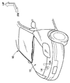
 図1には、本実施形態に係る車両用フード構造が適用された車両の前部が示されている。また、図2には、本実施形態に係る車両用フード構造の構成がフードインナパネルの車両上方側から見た状態で示されている。また、図3には、車両用フード構造のロックリインフォース付近の構成が縦断面図にて示されている。図1に示されるように、自動車(車両)10の車両本体の前部には、エンジンルームの上方を覆うようにフード12が設けられている。フード12は、車両前後方向の後端部に設けられた左右一対のヒンジアーム(図示省略)により、車両本体に対して前端部12Aが車両上下方向に開閉可能とされている。自動車10の車両本体のフード12の前端部12Aにおける車両幅方向中央部には、フードロック機構14が配設されている。 FIG. 1 shows a front portion of a vehicle to which the vehicle hood structure according to this embodiment is applied. FIG. 2 shows the configuration of the hood structure for a vehicle according to the present embodiment as viewed from the vehicle upper side of the hood inner panel. FIG. 3 is a longitudinal sectional view showing a configuration in the vicinity of the lock reinforcement of the vehicle hood structure. As shown in FIG. 1, a hood 12 is provided at a front portion of a vehicle main body of an automobile (vehicle) 10 so as to cover an upper portion of an engine room. The hood 12 has a pair of left and right hinge arms (not shown) provided at the rear end portion in the vehicle front-rear direction so that the front end portion 12A can be opened and closed in the vehicle vertical direction with respect to the vehicle body. A hood lock mechanism 14 is disposed at the center in the vehicle width direction of the front end 12 </ b> A of the hood 12 of the vehicle body of the automobile 10.
 図2及び図3に示されるように、フード12には、本実施形態の車両用フード構造20が適用されている。フード12は、車両上方側(車両外側)に車両幅方向及び車両前後方向に沿って配置されるフードアウタパネル22と、このフードアウタパネル22の車両下方側に車両幅方向及び車両前後方向に沿って配置されるフードインナパネル24と、を備えている。なお、図2では、本実施形態の車両用フード構造を分りやすくするために、フードアウタパネル22を二点鎖線で図示している。 As shown in FIGS. 2 and 3, the hood 12 of the present embodiment is applied to the hood 12. The hood 12 is disposed along the vehicle width direction and the vehicle front-rear direction on the vehicle upper side (vehicle outer side), and is disposed along the vehicle width direction and the vehicle front-rear direction on the vehicle lower side of the hood outer panel 22. Food inner panel 24. In FIG. 2, the hood outer panel 22 is illustrated by a two-dot chain line in order to make the vehicle hood structure of this embodiment easy to understand.
 フード12は、フードインナパネル24の周縁部24Aとフードアウタパネル22の周縁部22Aとがヘミング加工により一体化されることで閉断面構造に形成されている(図3参照)。すなわち、フードアウタパネル22はフード12の上面を構成すると共に、フードインナパネル24はフード12の下面を構成しており、フードアウタパネル22とフードインナパネル24との間は中空となっている。 The hood 12 is formed in a closed cross-sectional structure by integrating the peripheral edge 24A of the hood inner panel 24 and the peripheral edge 22A of the hood outer panel 22 by hemming (see FIG. 3). That is, the hood outer panel 22 constitutes the upper surface of the hood 12, and the hood inner panel 24 constitutes the lower surface of the hood 12, and the hood outer panel 22 and the hood inner panel 24 are hollow.
 フードインナパネル24の周縁部24Aの内側付近を除いた中央部領域には、車両前後方向に延びる複数の波形形状部40が車両幅方向に並列的に形成されている。複数の波形形状部40は、車両正面視にて車両上方側に屈曲する凸状部40Aと車両下方側に屈曲する凹状部40Bとが車両幅方向に交互に配置されている。すなわち、本発明の「複数のビード」には、複数の波形形状部40が含まれている。なお、フードインナパネル24の凸状部40Aの上面を、所定の箇所でフードアウタパネル22の下面に図示しない接着剤により接合してもよい。 In the central region excluding the vicinity of the inner side of the peripheral edge 24A of the hood inner panel 24, a plurality of corrugated portions 40 extending in the vehicle front-rear direction are formed in parallel in the vehicle width direction. In the plurality of waveform-shaped portions 40, convex portions 40A bent toward the vehicle upper side and concave portions 40B bent toward the vehicle lower side in the vehicle front view are alternately arranged in the vehicle width direction. That is, the “plurality of beads” of the present invention includes a plurality of waveform shape portions 40. Note that the upper surface of the convex portion 40A of the hood inner panel 24 may be bonded to the lower surface of the hood outer panel 22 with an adhesive (not shown) at a predetermined location.
 フードインナパネル24の前部の車両下方側には、車両前後方向及び車両幅方向に沿って延在するロックリインフォース26が配設されている(図2参照)。言い換えると、フードアウタパネル22の前部の車両下方側にロックリインフォース26が配置され、フードアウタパネル22とロックリインフォース26との間にフードインナパネル24の前端部が配置されている。図3に示されるように、ロックリインフォース26は、車両前後方向の後端部26Bに対して前端部26Aが段階的に車両下方側に屈曲する形状とされている。車両上下方向におけるフードインナパネル24とロックリインフォース26との間には、空間が形成されている。 A lock reinforcement 26 extending along the vehicle front-rear direction and the vehicle width direction is disposed on the vehicle lower side of the front portion of the hood inner panel 24 (see FIG. 2). In other words, the lock reinforcement 26 is disposed on the vehicle lower side of the front portion of the hood outer panel 22, and the front end portion of the hood inner panel 24 is disposed between the hood outer panel 22 and the lock reinforcement 26. As shown in FIG. 3, the lock reinforcement 26 has a shape in which the front end portion 26 </ b> A is bent stepwise toward the vehicle lower side with respect to the rear end portion 26 </ b> B in the vehicle front-rear direction. A space is formed between the hood inner panel 24 and the lock reinforcement 26 in the vehicle vertical direction.
 ロックリインフォース26の前端部26Aの端縁には、略平面状のフランジ部26Cが形成されている。フードインナパネル24の前端部には平面部24Bが形成されている。ロックリインフォース26のフランジ部26Cとフードインナパネル24の平面部24Bとが面接触状態で配置され、フランジ部26Cと平面部24Bがそれぞれボルト28とナット30により締結固定されている。フードインナパネル24の平面部24Bの上面(フード12の内部)には、予めナット30が溶接により固着されており、ロックリインフォース26の車両外側(車両下方側)からボルト28を差し込んでナット30に螺合させることで、フードインナパネル24の車両外側にロックリインフォース26が取り付けられている。 A substantially planar flange portion 26 </ b> C is formed on the edge of the front end portion 26 </ b> A of the lock reinforcement 26. A flat portion 24 </ b> B is formed at the front end of the hood inner panel 24. The flange portion 26C of the lock reinforcement 26 and the flat portion 24B of the hood inner panel 24 are arranged in a surface contact state, and the flange portion 26C and the flat portion 24B are fastened and fixed by bolts 28 and nuts 30, respectively. A nut 30 is fixed to the upper surface (inside of the hood 12) of the flat portion 24B of the hood inner panel 24 by welding in advance, and a bolt 28 is inserted into the nut 30 from the vehicle outer side (the vehicle lower side) of the lock reinforcement 26. The lock reinforcement 26 is attached to the vehicle outer side of the hood inner panel 24 by screwing.
 図2に示されるように、ロックリインフォース26の前端のフランジ部26Cとフードインナパネル24の平面部24Bとは、車両幅方向の複数箇所(本実施形態では5箇所)で、ボルト28とナット30により締結固定されている(図3参照)。また、ロックリインフォース26の車両幅方向両側の端部26Dとフードインナパネル24に車両幅方向両側に形成された平面部とが面接触状態で配置され、車両前後方向の複数箇所(本実施形態では3箇所)でロックリインフォース26の端部26Dとフードインナパネル24の平面部とがボルト28とナット30により締結固定されている。 As shown in FIG. 2, the flange portion 26 </ b> C at the front end of the lock reinforcement 26 and the flat portion 24 </ b> B of the hood inner panel 24 are a plurality of locations in the vehicle width direction (5 locations in the present embodiment), and bolts 28 and nuts 30. (See FIG. 3). Further, end portions 26D on both sides in the vehicle width direction of the lock reinforcement 26 and flat portions formed on both sides in the vehicle width direction on the hood inner panel 24 are arranged in a surface contact state, and a plurality of locations in the vehicle front-rear direction (in this embodiment) The end portion 26D of the lock reinforcement 26 and the flat portion of the hood inner panel 24 are fastened and fixed by bolts 28 and nuts 30 at three locations.
 すなわち、ロックリインフォース26の前端のフランジ部26C及び車両幅方向両側の端部26Dの3辺の所定の部位が、フードインナパネル24の前端の平面部24B及び車両幅方向両側の平面部に締結固定されている。図3に示されるように、ロックリインフォース26の車両幅方向中間部の後端部26Bの上面と、フードインナパネル24の複数の波形形状部40(凹状部40B)の下面との間は、非接触とされている。言い換えると、ロックリインフォース26の車両幅方向中間部の後端部26Bとフードインナパネル24の複数の波形形状部40(凹状部40B)とは、車両上下方向に隙間46を空けて配置されている。なお、ロックリインフォース26の車両幅方向中間部の後端部26Bとフードインナパネル24の複数の波形形状部40(凹状部40B)との車両上下方向の隙間46は、ロックリインフォース26の後端部26Bと複数の波形形状部40(凹状部40B)とが干渉しない範囲でなるべく狭くすることが望ましい。 That is, predetermined portions of the three sides of the flange portion 26C at the front end of the lock reinforcement 26 and the end portions 26D on both sides in the vehicle width direction are fastened and fixed to the plane portion 24B at the front end of the hood inner panel 24 and the plane portions on both sides in the vehicle width direction. Has been. As shown in FIG. 3, the gap between the upper surface of the rear end portion 26 </ b> B of the middle portion of the lock reinforcement 26 in the vehicle width direction and the lower surfaces of the plurality of corrugated portions 40 (concave portions 40 </ b> B) of the hood inner panel 24 is not. It is said to be in contact. In other words, the rear end portion 26B of the intermediate portion in the vehicle width direction of the lock reinforcement 26 and the plurality of corrugated portions 40 (concave portions 40B) of the hood inner panel 24 are arranged with a gap 46 in the vehicle vertical direction. . The clearance 46 in the vehicle vertical direction between the rear end portion 26B in the vehicle width direction intermediate portion of the lock reinforcement 26 and the plurality of corrugated portions 40 (concave portions 40B) of the hood inner panel 24 is the rear end portion of the lock reinforcement 26. It is desirable that the width 26B and the plurality of waveform-shaped portions 40 (concave portions 40B) be as narrow as possible without causing interference.
 図3に示されるように、ロックリインフォース26の前端部26Aには、車両下方側に屈曲された略平面状の横壁部26Eが形成されており、この横壁部26Eにフードロック機構14の一部を構成するストライカ32が取り付けられている。ストライカ32は、車両側面視にて車両前後方向に沿って配置される略「コ」字状の部材であり、ロックリインフォース26の横壁部26Eに形成された開口から車両本体側に垂下され、その両端部がベースプレート34を介して横壁部26Eに固定されている。ストライカ32は、フードロック機構14の車両本体側のラッチ部に係止されることで、フード12を車両本体側に閉止した状態とする。ロックリインフォース26は、ストライカ32を固定するために強度が必要であり、フードインナパネル24よりも板厚が厚い部材で形成されている。 As shown in FIG. 3, the front end portion 26A of the lock reinforcement 26 is formed with a substantially planar lateral wall portion 26E bent toward the vehicle lower side, and a part of the hood lock mechanism 14 is formed on the lateral wall portion 26E. The striker 32 which comprises is attached. The striker 32 is a substantially “U” -shaped member arranged along the vehicle front-rear direction in a side view of the vehicle, and is suspended from the opening formed in the lateral wall portion 26E of the lock reinforcement 26 toward the vehicle body side. Both end portions are fixed to the lateral wall portion 26E via the base plate 34. The striker 32 is in a state in which the hood 12 is closed to the vehicle main body side by being locked to the latch portion on the vehicle main body side of the hood lock mechanism 14. The lock reinforcement 26 needs strength to fix the striker 32, and is formed of a member having a plate thickness larger than that of the hood inner panel 24.
 図2及び図3に示されるように、フードインナパネル24の車両前後方向に延びる複数の波形形状部40の前端部40Cは、ロックリインフォース26の後端部26Bより車両前方側に位置している。すなわち、図2に示されるように、複数の波形形状部40の車両前後方向の長さAは、ロックリインフォース26の後端部26Bから複数の波形形状部40の後端部40Dまでの長さBよりも長く形成されている。フードインナパネル24の複数の波形形状部40は、フード12の車両上方側から衝突体80(図5参照)が衝突したときに、車両下方側に撓み変形が可能となっている。その際、複数の波形形状部40の前端部40Cを、ロックリインフォース26の後端部26Bより車両前方側に延在させることで、フードインナパネル24の広い範囲に応力を伝播することが可能となっている。 As shown in FIGS. 2 and 3, the front end portions 40 </ b> C of the plurality of corrugated portions 40 extending in the vehicle front-rear direction of the hood inner panel 24 are located on the vehicle front side from the rear end portion 26 </ b> B of the lock reinforcement 26. . That is, as shown in FIG. 2, the length A in the vehicle front-rear direction of the plurality of waveform shaped portions 40 is the length from the rear end portion 26B of the lock reinforcement 26 to the rear end portions 40D of the plurality of waveform shaped portions 40. It is formed longer than B. The plurality of waveform-shaped portions 40 of the hood inner panel 24 can be bent and deformed to the vehicle lower side when the collision body 80 (see FIG. 5) collides from the vehicle upper side of the hood 12. At that time, by extending the front end portions 40C of the plurality of waveform-shaped portions 40 to the vehicle front side from the rear end portion 26B of the lock reinforcement 26, it is possible to propagate stress over a wide range of the hood inner panel 24. It has become.
 また、フードインナパネル24における複数の波形形状部40の車両幅方向両側には、車両前後方向に延びるビード42が形成されている。ビード42は、複数の波形形状部40の車両前後方向の長さAよりも短く形成されており、ロックリインフォース26の後端部26Bより車両後方側に配置されている。また、ビード42は、車両後方外側に向けて車両内側の波形形状部40との間隔が開くように配置されている。 In addition, beads 42 extending in the vehicle front-rear direction are formed on both sides of the plurality of corrugated portions 40 in the hood inner panel 24 in the vehicle width direction. The bead 42 is formed to be shorter than the length A in the vehicle front-rear direction of the plurality of waveform-shaped portions 40, and is disposed on the vehicle rear side from the rear end portion 26 </ b> B of the lock reinforcement 26. Moreover, the bead 42 is arrange | positioned so that the space | interval with the waveform shape part 40 inside a vehicle may open toward the vehicle back outer side.
 なお、本実施形態では、フードインナパネル24の車両幅方向中間部に配置された複数の波形形状部40の前端部40Cが、ロックリインフォース26の後端部26Bよりも車両前方側に位置しているが、複数の波形形状部40の一部の前端部40Cがロックリインフォース26の後端部26Bよりも車両前方側に位置する構成でもよい。 In the present embodiment, the front end portions 40C of the plurality of waveform-shaped portions 40 disposed in the vehicle width direction intermediate portion of the hood inner panel 24 are positioned on the vehicle front side with respect to the rear end portion 26B of the lock reinforcement 26. However, a configuration in which some of the front end portions 40C of the plurality of waveform-shaped portions 40 are located on the vehicle front side with respect to the rear end portion 26B of the lock reinforcement 26 may be employed.
 次に、本実施形態の作用並びに効果について説明する。 Next, the operation and effect of this embodiment will be described.
 図3に示されるように、フードインナパネル24に設けられた車両前後方向に延びる複数の波形形状部40の前端部40Cは、ロックリインフォース26の後端部26Bよりも車両前方側に位置している。これによって、図4Aに示されるように、複数の波形形状部40の車両前後方向の長さAが、複数の波形形状部の前端部がロックリインフォース26の後端部26Bより車両後方側に配置された場合(図9及び図10A参照)に比べて長くなる。これによって、図4Bに示されるように、衝突荷重Wが作用したときにフードインナパネル24における複数の波形形状部40が撓む範囲がフード前後方向に広くなり、フードインナパネル24の広い範囲に応力が伝播される。 As shown in FIG. 3, front end portions 40 </ b> C of the plurality of waveform-shaped portions 40 provided in the hood inner panel 24 extending in the vehicle front-rear direction are located on the vehicle front side with respect to the rear end portion 26 </ b> B of the lock reinforcement 26. Yes. As a result, as shown in FIG. 4A, the length A in the vehicle front-rear direction of the plurality of waveform shaped portions 40 is arranged such that the front end portions of the plurality of waveform shaped portions are rearward of the rear end portion 26 </ b> B of the lock reinforcement 26. Compared to the case (see FIG. 9 and FIG. 10A), it becomes longer. As a result, as shown in FIG. 4B, the range in which the plurality of corrugated portions 40 in the hood inner panel 24 bend when the collision load W acts is widened in the hood front-rear direction, so that the hood inner panel 24 has a wide range. Stress is propagated.
 すなわち、図5に示されるように、フード12の車両上方側から衝突体80が衝突したときに、フードインナパネル24における複数の波形形状部40の広い領域が車両下方側に撓み(複数の波形形状部40がフード前後方向に大きく撓み)、フードインナパネル24の撓む範囲が拡大する。そのため、慣性マスが増え、慣性力が増加することで、フードインナパネル24の応力伝播範囲が広がり、エネルギー吸収性能が高まる。 That is, as shown in FIG. 5, when the collision body 80 collides from the vehicle upper side of the hood 12, a wide region of the plurality of waveform shaped portions 40 in the hood inner panel 24 bends to the vehicle lower side (a plurality of waveforms). The shape portion 40 is greatly bent in the hood front-rear direction), and the range of bending of the hood inner panel 24 is expanded. Therefore, an inertial mass increases and an inertial force increases, so that the stress propagation range of the hood inner panel 24 is expanded, and the energy absorption performance is enhanced.
 また、フードインナパネル24の車両下方側には、ロックリインフォース26が配置されており、ロックリインフォース26の後端部26Bが複数の波形形状部40(凹状部40B)に接近している。このため、図5に示されるように、フードインナパネル24における複数の波形形状部40が車両下方側に撓むことで、ロックリインフォース26の後端部26Bに当たり、ロックリインフォース26も一体となって車両下方側に撓み、衝撃時の荷重がロックリインフォース26に伝達される。すなわち、ロックリインフォース26にも衝撃時の荷重が分配されることで、エネルギー吸収性能を高めることができる。これによって、歩行者の頭部への荷重入力を低減することができ、歩行者保護性能を確保することができる。 Further, a lock reinforcement 26 is disposed on the vehicle lower side of the hood inner panel 24, and a rear end portion 26B of the lock reinforcement 26 is approaching a plurality of corrugated portions 40 (concave portions 40B). For this reason, as shown in FIG. 5, the plurality of corrugated portions 40 in the hood inner panel 24 bend to the vehicle lower side, so that they hit the rear end portion 26 </ b> B of the lock reinforcement 26 and the lock reinforcement 26 is also integrated. The vehicle is bent downward and the load at the time of impact is transmitted to the lock reinforcement 26. That is, energy absorption performance can be improved by distributing the load at the time of impact to the lock reinforcement 26 as well. Thereby, the load input to a pedestrian's head can be reduced and pedestrian protection performance can be ensured.
 また、ロックリインフォース26の後端部26Bとフードインナパネル24における複数の波形形状部40(凹状部40B)とが上下方向に隙間46を空けて配置されていることで、ロックリインフォース26の後端部26Bとフードインナパネル24との干渉が抑制され、NV性能を向上させることができる。 Further, the rear end portion 26B of the lock reinforcement 26 and the plurality of corrugated portions 40 (concave portions 40B) in the hood inner panel 24 are arranged with gaps 46 in the vertical direction, so that the rear end of the lock reinforcement 26 is provided. Interference between the portion 26B and the hood inner panel 24 is suppressed, and the NV performance can be improved.
 図8~図10Bには、比較例に係る車両用フード構造102を備えたフード100が示されている。 8 to 10B show a hood 100 including a vehicle hood structure 102 according to a comparative example.
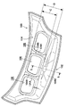
 図8に示されるように、フード100を構成するフードインナパネル104には、車両幅方向に所定の間隔をおいて略矩形状の3つの開口部106が形成されている。隣り合う開口部106の間には、車両前後方向に沿って延在される骨部104Aが設けられている。骨部104Aには、車両正面視にて車両上方側に突出するビード104Bが車両前後方向(長手方向)に沿って設けられている。図9に示されるように、フードインナパネル104におけるビード104Bの車両前方には、車両下方側に屈曲された縦壁部104Cが形成されており、縦壁部104Cより車両前方側には、車両前後方向及び車両幅方向に延在される横壁部(脆弱部)104Dが形成されている。 As shown in FIG. 8, the hood inner panel 104 constituting the hood 100 is formed with three substantially rectangular openings 106 at predetermined intervals in the vehicle width direction. Between adjacent openings 106, a bone portion 104A extending along the vehicle front-rear direction is provided. The bone portion 104A is provided with a bead 104B that protrudes upward in the vehicle when viewed from the front of the vehicle along the vehicle front-rear direction (longitudinal direction). As shown in FIG. 9, a vertical wall portion 104 </ b> C bent toward the vehicle lower side is formed in the front of the bead 104 </ b> B in the hood inner panel 104. A lateral wall portion (fragile portion) 104D extending in the front-rear direction and the vehicle width direction is formed.
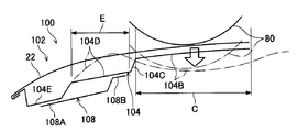
 フードインナパネル104の横壁部104Dの車両下方側には、ロックリインフォース108が配設されており、ロックリインフォース108の前端部108Aは、フードインナパネル104の前端部(横壁部104Dより車両前方側)に形成された平面部104Eに図示しない締結具で締結固定されている。車両側面視にてフードインナパネル104の複数(この比較例では2つ)のビード104Bの前端部は、ロックリインフォース108の後端部108Bよりも車両後方側に位置している。すなわち、複数のビード104Bの車両前後方向の長さCは、ロックリインフォース26の後端部26Bから複数のビード104Bの後端部までの長さDよりも短く形成されている(図8参照)。 A lock reinforcement 108 is disposed on the vehicle lower side of the lateral wall portion 104D of the hood inner panel 104, and a front end portion 108A of the lock reinforcement 108 is a front end portion of the hood inner panel 104 (the vehicle front side from the lateral wall portion 104D). It is fastened and fixed to the flat portion 104E formed by a fastener (not shown). The front end portions of a plurality of (two in this comparative example) beads 104B of the hood inner panel 104 are located on the vehicle rear side with respect to the rear end portion 108B of the lock reinforcement 108 in the vehicle side view. That is, the length C in the vehicle front-rear direction of the plurality of beads 104B is shorter than the length D from the rear end portion 26B of the lock reinforcement 26 to the rear end portions of the plurality of beads 104B (see FIG. 8). .
 この車両用フード構造102では、本実施形態の車両用フード構造20(図2参照)の複数の波形形状部40の車両前後方向の長さAに比べて、フードインナパネル104の複数のビード104Bの車両前後方向の長さCが短く、複数のビード104Bが車両下方側に撓む範囲が狭い。 In this vehicle hood structure 102, the plurality of beads 104B of the hood inner panel 104 are compared to the length A in the vehicle front-rear direction of the plurality of corrugated portions 40 of the vehicle hood structure 20 (see FIG. 2) of the present embodiment. The length C in the vehicle front-rear direction is short, and the range in which the plurality of beads 104B bend to the vehicle lower side is narrow.
 すなわち、図10A及び図10Bに示されるように、フード100の車両上方側から衝突体80が衝突したときに、衝突体80の衝撃に対するフードインナパネル104の応力伝播範囲が狭い。また、フードインナパネル104の複数のビード104Bが車両下方側に撓んでも、複数のビード104Bの車両前方側の縦壁部104Cが硬いため撓めず、縦壁部104Cが支点となり、ビード104Bを車両下方に、縦壁部104Cより車両前方側の横壁部(脆弱部)104Dを車両上方に略S字状に撓ませる。このため、フードインナパネル104は、フードインナパネル104より車両下方側に位置するロックリインフォース26に接触せず、衝撃荷重がロックリインフォース26に伝達されない。 That is, as shown in FIGS. 10A and 10B, when the collision body 80 collides from the vehicle upper side of the hood 100, the stress propagation range of the hood inner panel 104 with respect to the impact of the collision body 80 is narrow. Further, even if the plurality of beads 104B of the hood inner panel 104 are bent downward in the vehicle, the vertical wall portion 104C on the vehicle front side of the plurality of beads 104B is hard and does not bend, and the vertical wall portion 104C serves as a fulcrum, and the bead 104B Is bent downward in the vehicle, and the lateral wall portion (fragile portion) 104D on the front side of the vehicle with respect to the vertical wall portion 104C is bent in an approximately S shape above the vehicle. For this reason, the hood inner panel 104 does not come into contact with the lock reinforcement 26 positioned on the vehicle lower side than the hood inner panel 104, and the impact load is not transmitted to the lock reinforcement 26.
 これに対して、本実施形態の車両用フード構造20では、図2及び図3等に示されるように、フードインナパネル24における複数の波形形状部40の前端部40Cをロックリインフォース26の後端部26Bより車両前方側に延在させることで、比較例の車両用フード構造102に比べて、フードインナパネル24の応力伝播範囲が広くなる。このため、衝突体80が衝突したときに、フードインナパネル24の複数の波形形状部40の広い範囲に応力が伝播されることで、エネルギー吸収性能が高まる。また、本実施形態の車両用フード構造20では、フード12に同じ大きさの荷重Wが作用したときに、比較例の車両用フード構造102のフードインナパネル104の変位量に比べて、フードインナパネル24の車両下方側への変位量を小さくすることができる。このため、短いストロークでより多くのエネルギーを吸収することができる。さらに、フードインナパネル24の複数の波形形状部40が車両下方側に撓み、ロックリインフォース26の後端部26Bに当たることで、衝撃荷重がロックリインフォース26に伝達され、エネルギー吸収性能をより一層高めることができる。 On the other hand, in the vehicle hood structure 20 of the present embodiment, as shown in FIGS. 2 and 3, the front end portions 40 </ b> C of the plurality of waveform-shaped portions 40 in the hood inner panel 24 are connected to the rear end of the lock reinforcement 26. By extending the portion 26B to the front side of the vehicle, the stress propagation range of the hood inner panel 24 becomes wider than that of the vehicle hood structure 102 of the comparative example. For this reason, when the collision body 80 collides, the stress is propagated to a wide range of the plurality of waveform-shaped portions 40 of the hood inner panel 24, so that the energy absorption performance is enhanced. Further, in the vehicle hood structure 20 of the present embodiment, when the same load W acts on the hood 12, the hood inner is larger than the displacement amount of the hood inner panel 104 of the vehicle hood structure 102 of the comparative example. The amount of displacement of the panel 24 toward the vehicle lower side can be reduced. For this reason, more energy can be absorbed in a short stroke. Further, the plurality of corrugated portions 40 of the hood inner panel 24 bends downward in the vehicle and hits the rear end portion 26B of the lock reinforcement 26, whereby the impact load is transmitted to the lock reinforcement 26 and the energy absorption performance is further enhanced. Can do.
 次に、図6を用いて、本発明に係る車両用フード構造の第2実施形態について説明する。なお、前述した第1実施形態と同一構成部分については、同一番号を付してその説明を省略する。 Next, a second embodiment of the vehicle hood structure according to the present invention will be described with reference to FIG. In addition, about the same component as 1st Embodiment mentioned above, the same number is attached | subjected and the description is abbreviate | omitted.
 図6には、本実施形態の車両用フード構造52が適用されたフード50が示されている。この図に示されるように、フード50を構成するフードインナパネル24の車両下方側には、ロックリインフォース54が配設されており、ロックリインフォース54の後端部54Aとフードインナパネル24に形成された複数の波形形状部40(凹状部40B)とは、上下方向に非接触となるように配置されている。 FIG. 6 shows a hood 50 to which the vehicle hood structure 52 of the present embodiment is applied. As shown in this figure, a lock reinforcement 54 is disposed on the vehicle lower side of the hood inner panel 24 constituting the hood 50, and is formed on the rear end portion 54 </ b> A of the lock reinforcement 54 and the hood inner panel 24. The plurality of corrugated portions 40 (concave portions 40B) are arranged so as to be non-contact in the vertical direction.
 ロックリインフォース54の後端部54Aと複数の波形形状部40の凹状部40Bとの隙間には、ロックリインフォース54の後端部54Aとフードインナパネル24の複数の波形形状部40との干渉を緩和するためのシート状の隙詰め材56が介在されている。本実施形態では、隙詰め材56は、発泡樹脂で形成されている。なお、隙詰め材56の材料は、これに限定されず、不織布、繊維などからなる干渉緩和材でもよい。隙詰め材56は、ロックリインフォース54の後端部54Aの上面に接着剤等により固着されている。 In the gap between the rear end portion 54A of the lock reinforcement 54 and the concave portions 40B of the plurality of waveform shaped portions 40, interference between the rear end portion 54A of the lock reinforcement 54 and the plurality of waveform shaped portions 40 of the hood inner panel 24 is reduced. A sheet-like gap filling material 56 is interposed. In the present embodiment, the gap filling material 56 is formed of a foamed resin. The material of the gap filling material 56 is not limited to this, and may be an interference mitigation material made of a nonwoven fabric, fiber, or the like. The gap filling material 56 is fixed to the upper surface of the rear end portion 54A of the lock reinforcement 54 with an adhesive or the like.
 このような車両用フード構造52では、ロックリインフォース54の後端部54Aと複数の波形形状部40の凹状部40Bとの隙間に発泡樹脂製の隙詰め材56が配設されていることで、車両走行時のロックリインフォース54の後端部54Aとフードインナパネル24の複数の波形形状部40との干渉が緩和され、NV性能を向上させることができる。 In such a vehicular hood structure 52, the foamed resin gap filling material 56 is disposed in the gap between the rear end portion 54 </ b> A of the lock reinforcement 54 and the concave portions 40 </ b> B of the plurality of corrugated portions 40. Interference between the rear end portion 54A of the lock reinforcement 54 and the plurality of waveform-shaped portions 40 of the hood inner panel 24 when the vehicle is traveling is alleviated, and the NV performance can be improved.
 次に、図7を用いて、本発明に係る車両用フード構造の第3実施形態について説明する。なお、前述した第1実施形態及び第2実施形態と同一構成部分については、同一番号を付してその説明を省略する。 Next, a third embodiment of the vehicle hood structure according to the present invention will be described with reference to FIG. In addition, about the same component as 1st Embodiment and 2nd Embodiment mentioned above, the same number is attached | subjected and the description is abbreviate | omitted.
 図7には、本実施形態の車両用フード構造62が適用されたフード60が示されている。フード60を構成するフードインナパネル64の前端部の車両下方側には、ロックリインフォース68が配設されている。フードインナパネル64には、車両幅方向中央部に所定の間隔をおいて車両前後方向に長い略矩形状の2つの開口部66が形成されている。また、フードインナパネル64には、2つの開口部66の後部の車両幅方向両側に、開口部66よりも車両前後方向の長さが短い略矩形状の開口部67が形成されている。隣り合う開口部66の間、及び隣り合う開口部66と開口部67との間には、車両前後方向に沿って延在する骨部64A、64Bが設けられている。 FIG. 7 shows a hood 60 to which the vehicle hood structure 62 of this embodiment is applied. A lock reinforcement 68 is disposed on the vehicle lower side of the front end portion of the hood inner panel 64 constituting the hood 60. The hood inner panel 64 is formed with two substantially rectangular openings 66 that are long in the vehicle front-rear direction at a predetermined interval at the center in the vehicle width direction. The hood inner panel 64 is formed with a substantially rectangular opening 67 having a length in the vehicle front-rear direction shorter than the opening 66 on both sides in the vehicle width direction at the rear of the two openings 66. Bone portions 64 </ b> A and 64 </ b> B extending along the vehicle front-rear direction are provided between the adjacent openings 66 and between the adjacent openings 66 and 67.
 フードインナパネル64の車両幅方向中央部の骨部64Aには、車両正面視にて車両下方側へ突出する略断面ハット形状のビード74が車両前後方向に沿って形成されている。同様に、フードインナパネル64の車両幅方向両側の骨部64B及びその車両前方側の壁部には、車両正面視にて車両下方側へ突出する略断面ハット形状のビード74が車両前後方向に沿って形成されている。すなわち、各々車両前後方向に延びる3本のビード74は、車両幅方向に並列的に配置されている。3本のビード74は、車両前後方向の長さがほぼ同じに形成されており、ビード74の前端部74Aが、ロックリインフォース68の後端部68Bより車両前方側に位置している。ロックリインフォース68の前端部68Aは、フードインナパネル64の前端部に締結固定されている。ロックリインフォース68の後端部68Bの上面とビード74の下面との間は非接触とされている(ロックリインフォース68の後端部68Bとビード74とは、上下方向に隙間を空けて配置されている)。 A bead 74 having a substantially cross-sectional hat shape that protrudes toward the vehicle lower side when viewed from the front of the vehicle is formed in a bone portion 64A at the center in the vehicle width direction of the hood inner panel 64 along the vehicle front-rear direction. Similarly, a bead 74 having a substantially cross-sectional hat shape protruding in the vehicle lower side when viewed from the front of the vehicle is formed in the vehicle front-rear direction on the bone portions 64B on both sides in the vehicle width direction of the hood inner panel 64 and the wall portion on the vehicle front side. Are formed along. That is, the three beads 74 each extending in the vehicle front-rear direction are arranged in parallel in the vehicle width direction. The three beads 74 are formed to have substantially the same length in the vehicle front-rear direction, and the front end portion 74 </ b> A of the bead 74 is located on the vehicle front side from the rear end portion 68 </ b> B of the lock reinforcement 68. A front end portion 68 </ b> A of the lock reinforcement 68 is fastened and fixed to a front end portion of the hood inner panel 64. There is no contact between the upper surface of the rear end portion 68B of the lock reinforcement 68 and the lower surface of the bead 74 (the rear end portion 68B of the lock reinforcement 68 and the bead 74 are arranged with a gap in the vertical direction. )
 このような車両用フード構造62では、フードインナパネル64における複数のビード74の前端部74Aをロックリインフォース68の後端部68Bより車両前方側に延在させることで、比較例の車両用フード構造102(図9等参照)に比べて、複数のビード74が撓む範囲が広くなり、フードインナパネル64の応力伝播範囲が広くなる。このため、フード60の上方側から衝突体(図示省略)が衝突したときに、複数のビード74が車両下方側に撓み、フードインナパネル64の広い範囲に応力が伝播されることで、エネルギー吸収性能が高まる。さらに、フードインナパネル64の複数のビード74が車両下方側に撓み、ロックリインフォース68の後端部68Bに当たることで、衝撃荷重がロックリインフォース68に伝達され、エネルギー吸収性能をより一層高めることができる。 In such a vehicle hood structure 62, the front end portions 74 </ b> A of the plurality of beads 74 in the hood inner panel 64 extend from the rear end portion 68 </ b> B of the lock reinforcement 68 to the vehicle front side, so that the vehicle hood structure of the comparative example is provided. Compared to 102 (see FIG. 9 and the like), the range in which the plurality of beads 74 bend is widened, and the stress propagation range of the hood inner panel 64 is widened. For this reason, when a collision body (not shown) collides from the upper side of the hood 60, the plurality of beads 74 bend to the vehicle lower side, and stress is propagated to a wide range of the hood inner panel 64, thereby absorbing energy. Increases performance. Further, the plurality of beads 74 of the hood inner panel 64 bend downward in the vehicle and hit the rear end portion 68B of the lock reinforcement 68, whereby the impact load is transmitted to the lock reinforcement 68, and the energy absorption performance can be further enhanced. .
 なお、第1実施形態及び第2実施形態の複数の波形形状部40の形状や個数は、上記実施形態に限定するものではなく、変更が可能である。また、第3実施形態の複数のビード74の形状や個数は、上記実施形態に限定するものではなく、変更が可能である。 In addition, the shape and the number of the plurality of waveform shape portions 40 in the first embodiment and the second embodiment are not limited to the above-described embodiment, and can be changed. Further, the shape and number of the plurality of beads 74 of the third embodiment are not limited to the above-described embodiment, and can be changed.
 また、第1実施形態及び第2実施形態では、複数の波形形状部40の前端部40Cが、ロックリインフォースの後端部より車両前方側に位置しているが、これに限定されず、少なくとも1つの波形形状部40の前端部40Cが、ロックリインフォースの後端部より車両前方側に位置している構成でもよい。 Moreover, in 1st Embodiment and 2nd Embodiment, although the front-end part 40C of the some waveform shape part 40 is located in the vehicle front side from the rear-end part of lock reinforcement, it is not limited to this, At least 1 The front end portion 40C of the two wave shape portions 40 may be positioned on the vehicle front side from the rear end portion of the lock reinforcement.
 また、第3実施形態では、複数のビード74の前端部74Aが、ロックリインフォースの後端部より車両前方側に位置しているが、これに限定されず、少なくとも1つのビード74の前端部74Aが、ロックリインフォースの後端部より車両前方側に位置している構成でもよい。 In the third embodiment, the front end portions 74A of the plurality of beads 74 are located on the vehicle front side from the rear end portion of the lock reinforcement. However, the present invention is not limited to this, and the front end portions 74A of at least one bead 74 are provided. However, the structure located in the vehicle front side from the rear-end part of lock reinforcement may be sufficient.
 また、第1実施形態~第3実施形態の複数のビード(複数の波形形状部40を含む)は、車両後方に向けてビード間の間隔が徐々に広がる形状(扇型)や、車両幅方向最外側のビードだけ、又は車両幅方向最外側のビードを含めた2~3本のビードが斜めに傾いていてもよい。 In addition, the plurality of beads (including the plurality of corrugated portions 40) of the first to third embodiments have a shape (fan shape) in which the interval between the beads gradually increases toward the rear of the vehicle, Only the outermost bead or two to three beads including the outermost bead in the vehicle width direction may be inclined obliquely.

Claims (5)

  1.  フード外板を構成するフードアウタパネルと、
     前記フードアウタパネルの車両前部下方側に設けられ、フードロックを支持するロックリインフォースと、
     前記フードアウタパネルと前記ロックリインフォースとの間に前端部が配置され、フード内板を構成すると共に、各々車両前後方向に延びる複数のビードが車両幅方向に並列的に設けられ、かつ、少なくとも1つの前記ビードの前端部が前記ロックリインフォースの後端部より車両前方側に位置するように配置されたフードインナパネルと、
     を有する車両用フード構造。
    A hood outer panel constituting the hood outer plate;
    A lock reinforcement provided on the vehicle front lower side of the hood outer panel and supporting a hood lock;
    A front end portion is disposed between the hood outer panel and the lock reinforcement, constitutes a hood inner plate, and a plurality of beads each extending in the vehicle front-rear direction are provided in parallel in the vehicle width direction, and at least one A hood inner panel disposed such that a front end portion of the bead is positioned on the vehicle front side from a rear end portion of the lock reinforcement;
    A hood structure for a vehicle.
  2.  前記複数のビードは、複数の波形形状部により構成されている請求項1に記載の車両用フード構造。 The vehicle hood structure according to claim 1, wherein the plurality of beads are configured by a plurality of corrugated portions.
  3.  前記ビードは、前記フードインナパネルに設けられた複数の開口部の間に車両前後方向に沿って延在された複数の骨部に設けられている請求項1に記載の車両用フード構造。 The vehicle hood structure according to claim 1, wherein the bead is provided in a plurality of bone portions extending along a vehicle front-rear direction between a plurality of openings provided in the hood inner panel.
  4.  前記フードインナパネルの前部と前記ロックリインフォースの後端部とが上下方向に隙間を空けて配置されている請求項1から請求項3までのいずれか1項に記載の車両用フード構造。 The hood structure for a vehicle according to any one of claims 1 to 3, wherein a front portion of the hood inner panel and a rear end portion of the lock reinforcement are arranged with a gap in the vertical direction.
  5.  前記フードインナパネルの前部と前記ロックリインフォースの後端部との間には、両者の干渉を緩和するための隙詰め材が介在されている請求項4に記載の車両用フード構造。 The vehicle hood structure according to claim 4, wherein a gap filling material is interposed between a front portion of the hood inner panel and a rear end portion of the lock reinforcement for relieving interference therebetween.
PCT/JP2011/061457 2011-05-18 2011-05-18 Hood structure for vehicle WO2012157100A1 (en)

Priority Applications (5)

Application Number Priority Date Filing Date Title
EP11865774.1A EP2711271B1 (en) 2011-05-18 2011-05-18 Vehicle hood structure
US14/116,677 US9027987B2 (en) 2011-05-18 2011-05-18 Vehicle hood structure
CN201180070831.0A CN103517847B (en) 2011-05-18 2011-05-18 Hood structure for vehicle
PCT/JP2011/061457 WO2012157100A1 (en) 2011-05-18 2011-05-18 Hood structure for vehicle
JP2013514929A JP5556959B2 (en) 2011-05-18 2011-05-18 Vehicle hood structure

Applications Claiming Priority (1)

Application Number Priority Date Filing Date Title
PCT/JP2011/061457 WO2012157100A1 (en) 2011-05-18 2011-05-18 Hood structure for vehicle

Publications (1)

Publication Number Publication Date
WO2012157100A1 true WO2012157100A1 (en) 2012-11-22

Family

ID=47176463

Family Applications (1)

Application Number Title Priority Date Filing Date
PCT/JP2011/061457 WO2012157100A1 (en) 2011-05-18 2011-05-18 Hood structure for vehicle

Country Status (5)

Country Link
US (1) US9027987B2 (en)
EP (1) EP2711271B1 (en)
JP (1) JP5556959B2 (en)
CN (1) CN103517847B (en)
WO (1) WO2012157100A1 (en)

Cited By (4)

* Cited by examiner, † Cited by third party
Publication number Priority date Publication date Assignee Title
JP2014201143A (en) * 2013-04-03 2014-10-27 トヨタ自動車株式会社 Fiber-reinforced resin hood panel
JP2015009711A (en) * 2013-06-28 2015-01-19 トヨタ自動車株式会社 Vehicular hood structure
DE102013014203A1 (en) * 2013-08-26 2015-02-26 GM Global Technology Operations LLC (n. d. Ges. d. Staates Delaware) Front hood for a motor vehicle
CN104968557A (en) * 2013-02-08 2015-10-07 丰田铁工株式会社 Vehicle hood structure

Families Citing this family (17)

* Cited by examiner, † Cited by third party
Publication number Priority date Publication date Assignee Title
DE102014003199A1 (en) * 2014-03-04 2015-09-10 GM Global Technology Operations LLC (n. d. Ges. d. Staates Delaware) Front hood for a motor vehicle
JP6258108B2 (en) * 2014-04-09 2018-01-10 株式会社神戸製鋼所 Vehicle hood
US9393922B2 (en) * 2014-05-23 2016-07-19 Google Inc. Devices and methods for an energy-absorbing end of a vehicle
US9248866B2 (en) * 2014-06-13 2016-02-02 Toyota Motor Engineering & Manufacturing North America, Inc. Hood assembly
JP6020527B2 (en) * 2014-08-04 2016-11-02 トヨタ自動車株式会社 Vehicle hood structure
US9868472B2 (en) * 2014-09-19 2018-01-16 Mazda Motor Corporation Bonnet structure of automotive vehicle
JP6137139B2 (en) * 2014-11-21 2017-05-31 トヨタ自動車株式会社 Vehicle panel structure
JP6233327B2 (en) * 2015-02-05 2017-11-22 トヨタ自動車株式会社 VEHICLE PANEL STRUCTURE AND METHOD FOR MANUFACTURING VEHICLE PANEL STRUCTURE
JP6718726B2 (en) * 2016-03-31 2020-07-08 株式会社神戸製鋼所 Vehicle hood
JP6708070B2 (en) * 2016-09-09 2020-06-10 三菱自動車工業株式会社 Vehicle hood
JP6764453B2 (en) * 2018-09-27 2020-09-30 本田技研工業株式会社 Body front structure
WO2020145199A1 (en) * 2019-01-10 2020-07-16 日本製鉄株式会社 Automobile hood
US11884332B2 (en) * 2019-01-10 2024-01-30 Nippon Steel Corporation Automobile hood
US11286005B2 (en) * 2019-09-03 2022-03-29 Honda Motor Co., Ltd. Hood frame reinforcement for deflection mitigation
CN115335277A (en) * 2020-03-30 2022-11-11 日本制铁株式会社 Automobile engine cover
JP7360628B2 (en) * 2020-03-31 2023-10-13 マツダ株式会社 Vehicle front body structure
JP7338614B2 (en) * 2020-11-24 2023-09-05 トヨタ自動車株式会社 vehicle

Citations (5)

* Cited by examiner, † Cited by third party
Publication number Priority date Publication date Assignee Title
JP2005022569A (en) * 2003-07-04 2005-01-27 Toyota Motor Corp Hood structure for vehicle
JP2005075163A (en) * 2003-09-01 2005-03-24 Toyota Motor Corp Structure of hood for vehicle
JP2007223414A (en) * 2006-02-22 2007-09-06 Toyota Motor Corp Hood structure for vehicle
JP2008110668A (en) * 2006-10-30 2008-05-15 Kanto Auto Works Ltd Hood structure for vehicle
JP2008247394A (en) 2008-07-22 2008-10-16 Toyota Motor Corp Hood structure for vehicle

Family Cites Families (5)

* Cited by examiner, † Cited by third party
Publication number Priority date Publication date Assignee Title
KR20030074656A (en) 2000-12-13 2003-09-19 가부시키가이샤 고베 세이코쇼 Panel structure for car body hood
US7052079B2 (en) 2003-07-01 2006-05-30 Toyota Jidosha Kabushiki Kaisha Vehicular hood structure and vehicle body front portion structure
JP2005075176A (en) * 2003-09-01 2005-03-24 Toyota Motor Corp Structure of hood for vehicle
JP4719039B2 (en) * 2006-03-15 2011-07-06 株式会社神戸製鋼所 Automotive hood
DE602008003413D1 (en) * 2007-03-07 2010-12-23 Alcoa Inc MSTOFF

Patent Citations (5)

* Cited by examiner, † Cited by third party
Publication number Priority date Publication date Assignee Title
JP2005022569A (en) * 2003-07-04 2005-01-27 Toyota Motor Corp Hood structure for vehicle
JP2005075163A (en) * 2003-09-01 2005-03-24 Toyota Motor Corp Structure of hood for vehicle
JP2007223414A (en) * 2006-02-22 2007-09-06 Toyota Motor Corp Hood structure for vehicle
JP2008110668A (en) * 2006-10-30 2008-05-15 Kanto Auto Works Ltd Hood structure for vehicle
JP2008247394A (en) 2008-07-22 2008-10-16 Toyota Motor Corp Hood structure for vehicle

Non-Patent Citations (1)

* Cited by examiner, † Cited by third party
Title
See also references of EP2711271A4 *

Cited By (7)

* Cited by examiner, † Cited by third party
Publication number Priority date Publication date Assignee Title
CN104968557A (en) * 2013-02-08 2015-10-07 丰田铁工株式会社 Vehicle hood structure
EP2955085A4 (en) * 2013-02-08 2016-10-12 Toyota Tekko Kk Vehicle hood structure
US9688313B2 (en) 2013-02-08 2017-06-27 Toyoda Iron Works Co., Ltd. Vehicle hood structure
CN104968557B (en) * 2013-02-08 2018-01-05 丰田铁工株式会社 Engine cover for vehicle constructs
JP2014201143A (en) * 2013-04-03 2014-10-27 トヨタ自動車株式会社 Fiber-reinforced resin hood panel
JP2015009711A (en) * 2013-06-28 2015-01-19 トヨタ自動車株式会社 Vehicular hood structure
DE102013014203A1 (en) * 2013-08-26 2015-02-26 GM Global Technology Operations LLC (n. d. Ges. d. Staates Delaware) Front hood for a motor vehicle

Also Published As

Publication number Publication date
EP2711271A4 (en) 2014-03-26
JPWO2012157100A1 (en) 2014-07-31
EP2711271A1 (en) 2014-03-26
US9027987B2 (en) 2015-05-12
US20140062142A1 (en) 2014-03-06
CN103517847A (en) 2014-01-15
JP5556959B2 (en) 2014-07-23
CN103517847B (en) 2015-07-01
EP2711271B1 (en) 2015-01-14

Similar Documents

Publication Publication Date Title
JP5556959B2 (en) Vehicle hood structure
JP4059187B2 (en) Vehicle hood structure
JP5709610B2 (en) Hood panel for vehicle
JP6052408B2 (en) Body front structure
JP6717378B2 (en) Shock absorber
WO2011080835A1 (en) Hood structure of vehicle
JP5768739B2 (en) Vehicle end structure
JP2009051251A (en) Vehicle front part structure
JP2007223414A (en) Hood structure for vehicle
JP6237290B2 (en) Body front structure
JP5692033B2 (en) Vehicle hood structure
JP6156306B2 (en) Vehicle cowl structure
JP5888456B2 (en) Vehicle end structure
JP4798485B2 (en) Vehicle front bumper structure
JP2011246040A (en) Pedestrian protecting device for vehicle
JP2009051250A (en) Vehicle front part structure
JP2009274663A (en) Vehicle energy absorbing structure
JP6520694B2 (en) Vehicle front structure
JP2008001149A (en) Structure of side portion of vehicle
JP2006044312A (en) Car body front structure
JP2012224216A (en) Vehicle body front structure
JP6801502B2 (en) Front hood for vehicles
JP5772522B2 (en) Vehicle hood structure
JPWO2011132317A1 (en) Hood structure
JP2005119511A (en) Structure of cabin wall in car body

Legal Events

Date Code Title Description
121 Ep: the epo has been informed by wipo that ep was designated in this application

Ref document number: 11865774

Country of ref document: EP

Kind code of ref document: A1

ENP Entry into the national phase

Ref document number: 2013514929

Country of ref document: JP

Kind code of ref document: A

WWE Wipo information: entry into national phase

Ref document number: 14116677

Country of ref document: US

WWE Wipo information: entry into national phase

Ref document number: 2011865774

Country of ref document: EP

NENP Non-entry into the national phase

Ref country code: DE